EP3322143A1 - Detection method and device for digital intermediate frequency processing system, and computer storage medium - Google Patents
Detection method and device for digital intermediate frequency processing system, and computer storage medium Download PDFInfo
- Publication number
- EP3322143A1 EP3322143A1 EP16820795.9A EP16820795A EP3322143A1 EP 3322143 A1 EP3322143 A1 EP 3322143A1 EP 16820795 A EP16820795 A EP 16820795A EP 3322143 A1 EP3322143 A1 EP 3322143A1
- Authority
- EP
- European Patent Office
- Prior art keywords
- data
- detection
- processing system
- dif
- excitation data
- Prior art date
- Legal status (The legal status is an assumption and is not a legal conclusion. Google has not performed a legal analysis and makes no representation as to the accuracy of the status listed.)
- Withdrawn
Links
- 238000012545 processing Methods 0.000 title claims abstract description 189
- 238000001514 detection method Methods 0.000 title claims abstract description 160
- 238000003860 storage Methods 0.000 title claims abstract description 16
- 230000005284 excitation Effects 0.000 claims abstract description 103
- 238000000034 method Methods 0.000 claims abstract description 44
- 230000000737 periodic effect Effects 0.000 claims description 21
- 230000008569 process Effects 0.000 claims description 13
- 230000009467 reduction Effects 0.000 claims description 3
- 230000006870 function Effects 0.000 description 20
- 238000004891 communication Methods 0.000 description 10
- 238000001914 filtration Methods 0.000 description 6
- 238000010586 diagram Methods 0.000 description 5
- 230000005540 biological transmission Effects 0.000 description 4
- 238000004088 simulation Methods 0.000 description 4
- 239000013598 vector Substances 0.000 description 4
- 238000006243 chemical reaction Methods 0.000 description 3
- 230000008878 coupling Effects 0.000 description 3
- 238000010168 coupling process Methods 0.000 description 3
- 238000005859 coupling reaction Methods 0.000 description 3
- 230000010365 information processing Effects 0.000 description 3
- 238000013178 mathematical model Methods 0.000 description 3
- 230000003287 optical effect Effects 0.000 description 2
- 238000005070 sampling Methods 0.000 description 2
- 238000001228 spectrum Methods 0.000 description 2
- 238000012360 testing method Methods 0.000 description 2
- 230000006872 improvement Effects 0.000 description 1
- 238000009776 industrial production Methods 0.000 description 1
- 238000012986 modification Methods 0.000 description 1
- 230000004048 modification Effects 0.000 description 1
- 230000010355 oscillation Effects 0.000 description 1
Images


Classifications
-
- H—ELECTRICITY
- H04—ELECTRIC COMMUNICATION TECHNIQUE
- H04B—TRANSMISSION
- H04B1/00—Details of transmission systems, not covered by a single one of groups H04B3/00 - H04B13/00; Details of transmission systems not characterised by the medium used for transmission
- H04B1/02—Transmitters
- H04B1/04—Circuits
- H04B1/0475—Circuits with means for limiting noise, interference or distortion
-
- H—ELECTRICITY
- H04—ELECTRIC COMMUNICATION TECHNIQUE
- H04B—TRANSMISSION
- H04B17/00—Monitoring; Testing
- H04B17/30—Monitoring; Testing of propagation channels
- H04B17/391—Modelling the propagation channel
-
- H—ELECTRICITY
- H04—ELECTRIC COMMUNICATION TECHNIQUE
- H04L—TRANSMISSION OF DIGITAL INFORMATION, e.g. TELEGRAPHIC COMMUNICATION
- H04L25/00—Baseband systems
- H04L25/02—Details ; arrangements for supplying electrical power along data transmission lines
- H04L25/03—Shaping networks in transmitter or receiver, e.g. adaptive shaping networks
- H04L25/03006—Arrangements for removing intersymbol interference
- H04L25/03159—Arrangements for removing intersymbol interference operating in the frequency domain
-
- H—ELECTRICITY
- H04—ELECTRIC COMMUNICATION TECHNIQUE
- H04L—TRANSMISSION OF DIGITAL INFORMATION, e.g. TELEGRAPHIC COMMUNICATION
- H04L27/00—Modulated-carrier systems
- H04L27/26—Systems using multi-frequency codes
- H04L27/2601—Multicarrier modulation systems
- H04L27/2614—Peak power aspects
- H04L27/2623—Reduction thereof by clipping
- H04L27/2624—Reduction thereof by clipping by soft clipping
-
- G—PHYSICS
- G01—MEASURING; TESTING
- G01R—MEASURING ELECTRIC VARIABLES; MEASURING MAGNETIC VARIABLES
- G01R23/00—Arrangements for measuring frequencies; Arrangements for analysing frequency spectra
- G01R23/02—Arrangements for measuring frequency, e.g. pulse repetition rate; Arrangements for measuring period of current or voltage
- G01R23/14—Arrangements for measuring frequency, e.g. pulse repetition rate; Arrangements for measuring period of current or voltage by heterodyning; by beat-frequency comparison
-
- H—ELECTRICITY
- H04—ELECTRIC COMMUNICATION TECHNIQUE
- H04L—TRANSMISSION OF DIGITAL INFORMATION, e.g. TELEGRAPHIC COMMUNICATION
- H04L25/00—Baseband systems
- H04L25/02—Details ; arrangements for supplying electrical power along data transmission lines
- H04L25/03—Shaping networks in transmitter or receiver, e.g. adaptive shaping networks
Definitions
- the invention relates to the field of communications, and in particular to a method and apparatus for detecting a Digital Intermediate Frequency (DIF) processing system, and a computer storage medium.
- DIF Digital Intermediate Frequency
- a Remote Radio Unit is a bridge connecting a Base Band Unit (BBU) and a radio frequency unit.
- a DIF processing system in the RRU may perform DIF processing on a signal transmitted by the RRU.
- the correctness and stability of the DIF processing system are highly required. Otherwise, the problems of poor communication quality and the like will be caused.
- bit-level detection is preferably performed.
- DIF processing of the DIF processing system is performed according to a data stream instead of a data packet.
- the data stream fails to involve a packet header and a packet tail. Since a feedback ring is present during the DIF processing of the data stream, each data bit in the data stream will influence a subsequent processing result. Based on this, it is very difficult to perform bit-level correctness comparison by capturing a segment from the output data stream.
- an existing detection method refers to overall detection on the whole RRU transmission data. This detection method has the following problems.
- Detection is indirect detection on the DIF processing system via overall detection on RRU transmission data, rather than direct detection on the DIF processing system. Obviously, a detection result is not accurate.
- the embodiments of the invention are intended to provide a method and apparatus for detecting a DIF processing system, which are be able to solve at least one of low detection result accuracy, fault non-locating, high detection cost and low detection efficiency.
- the embodiments of the invention provide a method for detecting a DIF processing system.
- the method includes the steps as follows. Excitation data is formed. The excitation data is sent to the DIF processing system. Detection data formed by the DIF processing system processing the excitation data is collected. The detection data is compared with reference data bit by bit to form a detection result.
- the step that the excitation data is sent to the DIF processing system includes the sub-step as follows.
- the excitation data is sent to a downlink of the DIF processing system.
- the detection data includes: a downlink detection signal formed by sequentially performing Digital Up Converter (DUC) processing, Crest Factor Reduction (CFR) processing and Digital Pre-Distortion (DPD) processing on the excitation data via the downlink.
- DUC Digital Up Converter
- CFR Crest Factor Reduction
- DPD Digital Pre-Distortion
- the step that the excitation data is sent to the DIF processing system includes the sub-step as follows.
- the excitation data is sent to an uplink of the DIF processing system.
- the detection data includes: an uplink detection signal formed by performing Digital Down Converter (DDC) processing on the excitation data via the uplink.
- DDC Digital Down Converter
- the method may further include the steps as follows.
- a detection parameter is configured.
- the detection parameter includes an algorithm parameter and the algorithm parameter is consistent with an algorithm parameter forming the reference data.
- the detection parameter is a configuration parameter for the DIF processing system to process the excitation data.
- the excitation data is a periodic sequence sent periodically.
- an apparatus for detecting a DIF processing system includes an excitation data forming unit, configured to form excitation data; a sending unit, configured to send the excitation data to the DIF processing system; a collection unit, configured to collect detection data formed by via the DIF processing system processing the excitation data; and a comparison unit, configured to compare the detection data with reference data bit by bit to form a detection result.
- the sending unit is configured to send the excitation data to a downlink of the DIF processing system.
- the detection data includes: a downlink detection signal formed by sequentially performing DUC processing, CFR processing and DPD processing on the excitation data via the downlink.
- the sending unit is configured to send the excitation data to an uplink of the DIF processing system.
- the detection data includes: an uplink detection signal formed by performing DDC processing on the excitation data via the uplink.
- the apparatus may further include a configuration unit, configured to configure a detection parameter.
- the detection parameter includes an algorithm parameter and the algorithm parameter is consistent with an algorithm parameter forming the reference data.
- the detection parameter is a configuration parameter for the DIF processing system to process the excitation data.
- the excitation data is a periodic sequence sent periodically.
- a computer storage medium stores computer-executable instructions.
- the computer-executable instructions are used to execute the foregoing method for detecting a DIF processing system.
- excitation data is sent to the DIF processing system, detection data output via the DIF processing system is collected, and the detection data is compared with reference data to obtain a detection result.
- the detection data is data directly output by the DIF processing system. Accordingly, compared with data processed by other results in the related art, the detection data can more accurately represent the processing accuracy of the DIF processing system, and can accurately reflect the processing performance of the DIF processing system. Meanwhile, the detection result formed according to the detection data of the present invention can accurately reflect whether the DIF processing system is faulty.
- the detection method and apparatus of the present invention may utilize existing structures such as a Central Processing Unit (CPU) and a transmission link in an RRU without introduction of structures such as a spectrometer and a signal source, thereby reducing the hardware cost of detection. Moreover, it is unnecessary to set up different transmission links according to different communication modes, thereby increasing the detection efficiency.
- CPU Central Processing Unit
- the present embodiment provides a method for detecting a DIF processing system.
- the method includes the steps as follows.
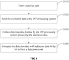
- step S110 excitation data is formed.
- step S120 the excitation data is sent to the DIF processing system.
- step S130 detection data formed by the DIF processing system processing the excitation data is collected.
- step S140 the detection data is compared with reference data bit by bit to form a detection result.
- the excitation data may be data dedicated to detection of the DIF processing system.
- the excitation data may be a data sequence with known data contents in advance and the like.
- step S120 the excitation data is sent to the DIF processing system for processing by the DIF processing system.
- step S130 detection data formed by the DIF processing system processing the excitation data is collected.
- the reference data is a correct result subject to intermediate frequency processing obtained in a pre-simulation manner and formed based on the excitation data. Therefore, the reference data is a correct result of intermediate frequency processing.
- the processing accuracy of the detected DIF processing system can be determined apparently.
- direct detection on a processing result (namely the detection data) of the detected DIF processing system will not influence a detection result by structures such as a processing structure in the RRU and a BBU, thereby increasing the accuracy of detection on the DIF processing system.
- the content of the excitation data can be known in advance, and the excitation data is compared with reference data formed based on the excitation data bit by bit, so as to implement bit-level detection on the DIF processing system and to ensure the accuracy of the detection result again.
- the processing result of the DIF processing system is directly detected, if it is considered that the accuracy of the detection result is too low, it may be directly determined whether the DIF processing system is faulty, thereby solving the problem in the related art in which a fault point cannot be located. Moreover, in the present embodiment, it is unnecessary to specially set up a detection environment, and an existing structure in an RRU can be directly used for detection, thereby reducing the hardware cost, and increasing the detection efficiency.
- the DIF processing system may include an uplink and a downlink. Uplink detection and downlink detection will be introduced in detail below respectively.
- the downlink detection is as follows.
- Step S120 may include: sending the excitation data to the downlink of the DIF processing system.
- the detection data includes: a downlink detection signal formed by sequentially performing DUC processing, CFR processing and DPD processing on the excitation data via the downlink.
- the downlink of the DIF processing system may include: a DUC module, a CFR module and a DPD processing module.
- the DUC module can perform DUC processing
- the CFR module is used to perform CFR processing
- the DPD processing module is used to perform DPD processing.
- the DUC module includes an interpolation filter group and a Numerically Controlled Oscillator (NCO).
- the DUC processing includes interpolation filtering of the interpolation filter group and digital mixing of the NCO.
- the excitation data may be formed by a CPU in FIG. 2 , and sent to the downlink of the DIF processing system via a Test Signal Generator (TSG) unit.
- TSG Test Signal Generator
- step S130 data output by the downlink of the DIF processing system is collected by means of a Maintain And Test (MAT) unit, so as to obtain the detection data.
- the detection data is returned to the CPU and compared with reference data.
- the CPU may be replaced with any processor or processing circuit.
- the processor may include a structure having information processing and control, such as an Application Processor (AP), a Micro Control Unit (MCU), a Digital Signal Processor (DSP), a Programmable Logic Controller (PLC) or the like.
- the processing circuit may include a structure such as an Application Specific Integrated Circuit (ASIC).
- ASIC Application Specific Integrated Circuit
- the uplink detection is as follows.
- Step S120 may include sending the excitation data to the uplink of the DIF processing system.
- the detection data includes an uplink detection signal formed by performing DDC processing on the excitation data via the uplink.
- the uplink of the DIF processing system may include a DDC unit.
- the DDC unit includes an NCO and a decimation filter group.
- the DDC unit can be used to perform DDC processing on the excitation data.
- the DDC processing includes digital mixing via the NCO and decimation filtering performed by the decimation filter group.
- the detection data may include an uplink detection signal formed by performing DIF processing via the uplink of the DIF processing system.
- Devices such as the TSG unit, the CPU and the MAT in FIG. 2 and FIG. 3 may be existing structures in the RRU, and the bit-level detection on the DIF processing system is achieved by reusing these structures. Therefore, the characteristic of low hardware cost is provided, and it is unnecessary to specially set up a corresponding detection environment.
- the method further includes the steps as follows.
- a detection parameter is configured.
- the detection parameter includes an algorithm parameter, the algorithm parameter being consistent with an algorithm parameter forming the reference data.
- the detection parameter is a configuration parameter for the DIF processing system to process the excitation data.
- the method in the present embodiment further includes: configuring a detection parameter.
- a processing parameter of DIF processing for forming reference data should keep consistent with a detection parameter of the detected DIF processing system.
- An algorithm parameter of the detected DIF processing system for DIF processing should be, at least, consistent with an algorithm parameter for forming the reference data. Accordingly, the detection parameter is pre-configured in the present embodiment, and the algorithm parameter in the detection parameter is consistent with the algorithm parameter of the reference data.
- the detection parameter may further include other parameters such as a collection period, a collection frequency and a processing frequency. These parameters may be configured with reference to the related art, and will not be illustrated herein.
- the excitation data is a periodic sequence sent periodically.
- the excitation data is a 32bit periodic sequence sent periodically.
- the periodic sequence is utilized for detection, so that during discrete repeated detection or successive repeated detection, it is unnecessary to form the reference signal in other forms such as simulation at each time.
- forming of reference data can be simplified, thereby simplifying the operation.
- the excitation data may also be a non-periodic sequence which is randomly formed.
- the reference data is formed by simulation processing on each excitation data. As such, the DIF processing system can be also detected.
- a detection parameter is formed according to an algorithm parameter of an algorithm model, and the DIF processing system is configured with the detection parameter.
- An excitation data forming unit sends the excitation data to the algorithm model and a TSG unit respectively, and the TSG unit sends the excitation data to the DFI processing system.
- the DFI processing system performs DFI processing, and the algorithm model performs simulation processing and the like.
- the algorithm model outputs reference data, the MAT unit collects detection data, and the detection data and the reference data are compared to form the detection result in the embodiment of the present application.
- the detection data in the embodiment of the present application is data output by the DFI processing system directly.
- FIG. 2 and FIG. 3 Each processing structure in the DFI processing system is involved in FIG. 2 and FIG. 3 .
- Various types of DFI processing performed on the above-mentioned structure are relevantly introduced as follows.
- the interpolation filter group is mainly used to perform interpolation and convolution operation.
- interpolation filtering if periodic check data is output, an output result is periodic after N-time interpolation, and a cycle period is N times a period inputting check data.
- convolution operation although data input at a current time influences output of data at the following K (the value of K is equal to the length of a filter coefficient) times, the periodicity of the output result cannot be influenced. That is, if the period inputting check data is M, the output data is a sequence of which the period is N*M after the interpolation filter group performs N-times interpolation. Accordingly, the output result of the interpolation filter group can be determined by selecting periodic excitation data and an interpolation multiple.
- a sine-cosine digital signal is generated, and then the sine-cosine signal is multiplied by a signal to be mixed, so as to complete a function of transferring the signal to be mixed over a spectrum of a frequency domain. Because the sine-cosine signal is equivalent to a spectrum pulse in the frequency domain, multiplying of signals in a time domain is equivalent to convolution processing in the frequency domain. A convolution result of a pulse signal and other signals is that the pulse signal completes a process of completely transferring other signals to a pulse point.
- f LO is a local oscillation frequency
- f S is a sampling frequency of a corresponding signal.
- a data vector to be selected is required to satisfy W ⁇ ( L + P -1).
- the CFR processing in the present embodiment can utilize hard CFR or pulse offset CFR.
- Hard CFR is implemented by judging signal instantaneous power.
- a signal is not processed, and when the signal power is greater than the threshold, the signal amplitude is equal to the threshold.
- selected excitation data x ( n ) is a sequence of which the period is M, and a cycle period of an output signal y ( n ) thereof is also M after the hard CFR. Accordingly, after the input periodic excitation data x ( n ) is selected, an output result of the hard CFR can be determined.
- a pulse offset CFR algorithm is based on a principle of a linear system and based on an idea of signal superposition. That is, a signal envelope opposite to the processed signal is generated, and superposed with an original signal.
- x ( n ) in the function relation (5) in the present application comes from data of excitation data of a periodic sequence, a period being set as M; and c ( n ) is also a periodic sequence, a corresponding period being set as N. If y(n) is a sequence of which has the period L, L is a lowest common multiple of M and N.
- Crest value search may adopt three-point crest search or four-point crest search.
- the crest value search is analyzed with four-point crest search as an example.
- Other crest search manners may be slightly different from four-point crest search.
- contained basic operations are the same from the perspective of mathematical processing.
- a module value is solved by converting an input sequence from a rectangular coordinate system to a polar coordinate system, which has been analyzed above. If an input signal is a periodic sequence, an output signal thereof may keep the original periodicity, and is still a periodic sequence. After the module value of the input sequence is obtained, the module value is compared with a CFR threshold. If the module value is greater than the CFR threshold, a difference value obtained by subtracting the CFR threshold from the module value is adopted, and otherwise, 0 is adopted. A main operation on an input sequence in this process is a subtraction operation, and does not influence the periodicity thereof. Finally, the four-point crest search is performed.
- the basic principle is as follows.
- the secondary crest search usually adopts a sliding window crest search method.
- the secondary crest search includes: saving a current crest value, starting to count from the location of the crest value, and waiting for a next crest value; if the coming time of the next crest value has exceeded the length of a window, reserving the saved crest value, and starting to recount from the new crest value; and if the coming time of the next crest value does not exceed the length of the window, saving a larger one between the two crest values, and continuing search; if the latter is larger, restarting to count by a counter.
- the sliding window crest search is similar to the four-point crest search, and a mathematical operation for an input sequence thereof may come down to a subtraction operation. Accordingly, if the period of the input sequence is M, the period of an output sequence is also M after the sliding window crest search.
- a generated offset pulse c ( n ) is also a periodic sequence. Accordingly, in a successive data stream output by offset pulse CFR, if any one collected successive detection data is a subset of reference data, it is considered that detection is passed. When the detection data is compared with the reference data, the detection data and the reference data are regarded as vectors. During bit-by-bit matching and comparison, it is required to ensure that data at corresponding locations are identical. As such, it is considered that a detection result corresponding to successful bit matching is correct.
- the DPD processing may adopt a memory polynomial model structure. If the number of lookup tables is N, a mathematical model of the DPD may be expressed by a function relation (6).
- f i ( x ) , h i and k i may be all configured by means of a detection parameter according to a forming parameter of a reference signal, and may be configured by means of a CPU as shown in FIG. 2 and FIG. 3 specifically.
- the DPD processing mainly includes a multiplication operation and an addition operation.
- the processing procedure does not influence the periodicity of data. Therefore, if excitation data X ( n ) is a sequence of which the period is M, after the DPD processing, a cycle period of an output signal Y DPD ( n ) thereof is also M. Therefore, in a successive data stream outputted by the DPD, if any one collected successive detection data is multiple bits successively distributed in reference data, it is considered that detection is passed.
- the detection process of the downlink is illustrated with an example as follows.
- TSG input excitation data of the downlink is a sequence of which the period is M
- a DUC interpolation filter group performs N-times interpolation filtering.
- digital mixing is performed. If the period of an NCO is K (K is a denominator of a simplest fraction f LO f S ) , the period of data output by the NCO is P (P is a lowest common multiple of L and K).
- CFR adopts an offset pulse CFR algorithm containing a double interpolation filter, double decimation filter, four-point crest search and sliding window crest search and offset pulse forming module
- output data is still a sequence of which the period is P after being subjected to CFR processing.
- final data output by the downlink is the sequence of which the period is P.
- TSG input excitation data is a sequence of which the period is M, and a downlink configuration parameter is given.
- the overall output of the downlink is determined, and in a successive data stream, if any one collected successive detection data is a subset of reference data, it is considered that detection is passed.
- the subset in the embodiment of the present application may be interpreted as that it is supposed that the reference data is 1024 numbers (each number is 32bit), if detection data only has 512 numbers which exactly are 512 numbers successively distributed in the foregoing 1024 numbers, so it is considered that the detection data is a subset of the reference data.
- the present embodiment provides an apparatus for detecting a DIF processing system.
- the apparatus includes an excitation data forming unit 110, a sending unit 120, a collection unit 130, and a comparison unit 140.
- the excitation data forming unit 110 is configured to form excitation data.
- the sending unit 120 is configured to send the excitation data to the DIF processing system.
- the collection unit 130 is configured to collect detection data formed by the DIF processing system processing the excitation data.
- the comparison unit 140 is configured to compare the detection data with reference data bit by bit to form a detection result.
- the apparatus for detecting the DIF processing system in the present embodiment may be a structure integrated in an RRU.
- the excitation data forming unit 110 may be a CPU as shown in FIG. 2 or FIG. 3 .
- the excitation data forming unit 110 in the present embodiment may also be an information processor having excitation data forming such as an MCU, a DSP or a PLC.
- the excitation data forming unit may also be a structure such as an ASIC.
- a specific structure of the sending unit 120 may include a communication interface.
- the communication interface may be used to send excitation data formed by the excitation data forming unit 110 to the DIF processing system in the RRU.
- the sending unit 120 in the present embodiment may be a TSG unit as shown in FIG. 2 or FIG. 3 .
- the collection unit 130 in the present embodiment may include a collector, which may be used to collect data from an output result of the DIF processing system to form the detection data.
- the collection unit 130 in the present embodiment may be an MAT unit as shown in FIG. 2 or FIG. 3 .
- the excitation data in the present embodiment may be data formed randomly, or may be data formed according to a specified generation policy.
- the excitation data is a periodic sequence sent periodically.
- the excitation data is a periodic sequence, which may reduce a reference signal, and meanwhile, facilitate the collection unit 130 to collect a detection signal at any time at will.
- a specific structure of the comparison unit 140 may be a CPU having an information processing structure.
- a detection result can be formed by comparing the detection data with the reference data.
- the sending unit 120 is configured to send the excitation data to a downlink of the DIF processing system.
- the detection data includes a downlink detection signal formed by sequentially performing DUC processing, CFR processing and DPD processing on the excitation data via the downlink.
- the sending unit 120 is further configured to send the excitation data to an uplink of the DIF processing system.
- the detection data includes an uplink detection signal formed by performing DDC processing on the excitation data via the uplink.
- the sending unit 120 in the present embodiment can send the excitation data to the downlink and the uplink of the DIF processing system.
- the uplink of the DIF processing system and the downlink of the DIF processing system are connected, and the excitation data can be sent to the uplink and the downlink.
- the apparatus may further include a configuration unit, configured to configure a detection parameter.
- the detection parameter includes an algorithm parameter, the algorithm parameter being consistent with an algorithm parameter forming the reference data.
- the detection parameter is a configuration parameter for the DIF processing system to process the excitation data.
- the configuration unit in the present embodiment may correspond to a processor or processing structure having an information processing function in the RRU.
- the configuration unit may correspond to the CPU in FIG. 2 or FIG. 3 .
- the excitation data forming unit 110, the comparison unit 140 and the configuration unit may correspond to different processors or processing circuits respectively, or may integrally correspond to the same processor or processing circuit. In the present embodiment, alternatively, the units correspond to the same processor or processing circuit.
- the processor or processing circuit adopts a time division multiplexing method to achieve functions of the excitation data forming unit 110, the comparison unit 140 and the configuration unit.
- the apparatus for detecting a DIF processing system in the present embodiment can be applied to the method for detecting a DIF processing system in the foregoing method embodiment, and can simply and accurately detect the DIF processing system with low cost.
- the embodiment of the invention also provides a computer storage medium.
- the computer storage medium stores computer-executable instructions.
- the computer-executable instructions are used to execute the method for detecting a DIF processing system provided in any one of the foregoing technical solutions, such as the method as shown in FIG. 1 and/or FIG. 4 .
- the computer storage medium may be various storage media capable of storing program codes such as a mobile storage device, a Read-Only Memory (ROM), a Random Access Memory (RAM), a magnetic disk or an optical disk, and is a non-transitory storage medium alternatively.
- ROM Read-Only Memory
- RAM Random Access Memory
- magnetic disk or an optical disk and is a non-transitory storage medium alternatively.
- the disclosed device and method may be implemented in other manner.
- the apparatus embodiment described above is merely schematic.
- division of the units is merely logic function division, and other division manners may be adopted during practical implementation.
- a plurality of units or components may be combined or integrated into another system, or some characteristics may be neglected or not executed.
- coupling or direct coupling or communication connection between the displayed or discussed components may be indirect coupling or communication connection, implemented through some interfaces, of the devices or the units, and may be electrical and mechanical or adopt other forms.
- the units described as separate parts may or may not be physically separated, and parts displayed as units may or may not be physical units, namely may be located in the same place or may also be distributed to a plurality of network units. Part or all of the units may be selected to achieve the purpose of the solutions of the present embodiment according to a practical requirement.
- each function unit in each embodiment of the invention may be integrated into a processing unit, each unit may also be present independently, and two or more than two units may also be integrated into a unit.
- the integrated unit may be implemented in a form of hardware, or may be implemented in a form of hardware and software function unit.
- the foregoing storage medium includes: various media capable of storing program codes such as a mobile storage device, an ROM, an RAM, a magnetic disk or an optical disk.
- detection data outputted by a DIF processing system is directly collected for comparison to obtain a detection result.
- the accuracy of the detection result can be increased and simple promotion and use in industrial production may be realized.
Landscapes
- Engineering & Computer Science (AREA)
- Computer Networks & Wireless Communication (AREA)
- Signal Processing (AREA)
- Physics & Mathematics (AREA)
- Electromagnetism (AREA)
- Power Engineering (AREA)
- Arrangements For Transmission Of Measured Signals (AREA)
- Digital Transmission Methods That Use Modulated Carrier Waves (AREA)
- Compression, Expansion, Code Conversion, And Decoders (AREA)
- Testing And Monitoring For Control Systems (AREA)
- Monitoring And Testing Of Transmission In General (AREA)
Abstract
Description
- The invention relates to the field of communications, and in particular to a method and apparatus for detecting a Digital Intermediate Frequency (DIF) processing system, and a computer storage medium.
- In a radio communication system, a Remote Radio Unit (RRU) is a bridge connecting a Base Band Unit (BBU) and a radio frequency unit. A DIF processing system in the RRU may perform DIF processing on a signal transmitted by the RRU. In order to reduce interference to a baseband signal generated by the BBU and a radio frequency signal formed by the radio frequency unit, the correctness and stability of the DIF processing system are highly required. Otherwise, the problems of poor communication quality and the like will be caused. In such a way, during detection of the processing accuracy and stability of the DIF processing system, bit-level detection is preferably performed.
- However, DIF processing of the DIF processing system is performed according to a data stream instead of a data packet. The data stream fails to involve a packet header and a packet tail. Since a feedback ring is present during the DIF processing of the data stream, each data bit in the data stream will influence a subsequent processing result. Based on this, it is very difficult to perform bit-level correctness comparison by capturing a segment from the output data stream.
- Due to large difficulty in bit-level detection, an existing detection method refers to overall detection on the whole RRU transmission data. This detection method has the following problems.
- Detection is indirect detection on the DIF processing system via overall detection on RRU transmission data, rather than direct detection on the DIF processing system. Obviously, a detection result is not accurate.
- When a detection result shows a problem, it is not able to be accurately determined whether the problem comes from the DIF processing system.
- During detection, it is necessary to set up a detection environment. When the detection environment is set up, instruments such as a BBU, a spectrometer and a signal source are needed. Apparently, the cost of a detection device is high, setup of the detection environment wastes time and energy, and the detection efficiency is low. Particularly, every time a communication mode is detected for a system supporting various communication modes, it is necessary to re-set up an environment.
- In view of this, the embodiments of the invention are intended to provide a method and apparatus for detecting a DIF processing system, which are be able to solve at least one of low detection result accuracy, fault non-locating, high detection cost and low detection efficiency.
- The technical solutions of the invention are implemented as follows.
- The embodiments of the invention provide a method for detecting a DIF processing system. The method includes the steps as follows. Excitation data is formed. The excitation data is sent to the DIF processing system. Detection data formed by the DIF processing system processing the excitation data is collected. The detection data is compared with reference data bit by bit to form a detection result.
- Based on the above-mentioned solution, the step that the excitation data is sent to the DIF processing system includes the sub-step as follows. The excitation data is sent to a downlink of the DIF processing system. The detection data includes: a downlink detection signal formed by sequentially performing Digital Up Converter (DUC) processing, Crest Factor Reduction (CFR) processing and Digital Pre-Distortion (DPD) processing on the excitation data via the downlink.
- Based on the above-mentioned solutions, the step that the excitation data is sent to the DIF processing system includes the sub-step as follows. The excitation data is sent to an uplink of the DIF processing system. The detection data includes: an uplink detection signal formed by performing Digital Down Converter (DDC) processing on the excitation data via the uplink.
- Based on the above-mentioned solutions, the method may further include the steps as follows. A detection parameter is configured. The detection parameter includes an algorithm parameter and the algorithm parameter is consistent with an algorithm parameter forming the reference data.
- Herein, the detection parameter is a configuration parameter for the DIF processing system to process the excitation data.
- Based on the above-mentioned solutions, the excitation data is a periodic sequence sent periodically.
- According to a second aspect of the embodiments of the invention, an apparatus for detecting a DIF processing system is also provided. The apparatus includes an excitation data forming unit, configured to form excitation data; a sending unit, configured to send the excitation data to the DIF processing system; a collection unit, configured to collect detection data formed by via the DIF processing system processing the excitation data; and a comparison unit, configured to compare the detection data with reference data bit by bit to form a detection result.
- Based on the above-mentioned solutions, the sending unit is configured to send the excitation data to a downlink of the DIF processing system. The detection data includes: a downlink detection signal formed by sequentially performing DUC processing, CFR processing and DPD processing on the excitation data via the downlink.
- Based on the above-mentioned solutions, the sending unit is configured to send the excitation data to an uplink of the DIF processing system. The detection data includes: an uplink detection signal formed by performing DDC processing on the excitation data via the uplink.
- Based on the above-mentioned solutions, the apparatus may further include a configuration unit, configured to configure a detection parameter. The detection parameter includes an algorithm parameter and the algorithm parameter is consistent with an algorithm parameter forming the reference data.
- Herein, the detection parameter is a configuration parameter for the DIF processing system to process the excitation data.
- Based on the above-mentioned solutions, the excitation data is a periodic sequence sent periodically.
- According to a third aspect of the embodiments of the invention, a computer storage medium is also provided. The computer storage medium stores computer-executable instructions. The computer-executable instructions are used to execute the foregoing method for detecting a DIF processing system.
- According to the method and apparatus for detecting a DIF processing system in the embodiments of the invention, excitation data is sent to the DIF processing system, detection data output via the DIF processing system is collected, and the detection data is compared with reference data to obtain a detection result. In the application, the detection data is data directly output by the DIF processing system. Accordingly, compared with data processed by other results in the related art, the detection data can more accurately represent the processing accuracy of the DIF processing system, and can accurately reflect the processing performance of the DIF processing system. Meanwhile, the detection result formed according to the detection data of the present invention can accurately reflect whether the DIF processing system is faulty. The problem in the related art in which a fault cannot be located due to data processing via a result rather than the result of a DIF processing system will not be caused. In addition, the detection method and apparatus of the present invention may utilize existing structures such as a Central Processing Unit (CPU) and a transmission link in an RRU without introduction of structures such as a spectrometer and a signal source, thereby reducing the hardware cost of detection. Moreover, it is unnecessary to set up different transmission links according to different communication modes, thereby increasing the detection efficiency.
-
-
FIG. 1 is a flow diagram of a method for detecting a DIF processing system according to an embodiment of the invention. -
FIG. 2 is a flow diagram of a downlink signal of a DIF processing system according to an embodiment of the invention. -
FIG. 3 is a flow diagram of an uplink signal of a DIF processing system according to an embodiment of the invention. -
FIG. 4 is a flow diagram of another method for detecting a DIF processing system according to an embodiment of the invention. -
FIG. 5 is a structure diagram of an apparatus for detecting a DIF processing system according to an embodiment of the invention. - The technical solutions of the invention will be further elaborated below in conjunction with the drawings of the description and specific embodiments. It will be appreciated that preferred embodiments described below are only used to describe and explain the invention, and not used to limit the invention.
- As shown in
FIG. 1 , the present embodiment provides a method for detecting a DIF processing system. The method includes the steps as follows. - In step S110, excitation data is formed.
- In step S120, the excitation data is sent to the DIF processing system.
- In step S130, detection data formed by the DIF processing system processing the excitation data is collected.
- In step S140, the detection data is compared with reference data bit by bit to form a detection result.
- The excitation data may be data dedicated to detection of the DIF processing system. The excitation data may be a data sequence with known data contents in advance and the like.
- In step S120, the excitation data is sent to the DIF processing system for processing by the DIF processing system.
- In step S130, detection data formed by the DIF processing system processing the excitation data is collected.
- In step S140, the reference data is a correct result subject to intermediate frequency processing obtained in a pre-simulation manner and formed based on the excitation data. Therefore, the reference data is a correct result of intermediate frequency processing. By means of a bit-by-bit comparison with the detection data, the processing accuracy of the detected DIF processing system can be determined apparently.
- According to the method for detecting a DIF processing system in the present embodiment, compared with detection on the whole RRU, direct detection on a processing result (namely the detection data) of the detected DIF processing system will not influence a detection result by structures such as a processing structure in the RRU and a BBU, thereby increasing the accuracy of detection on the DIF processing system. During a detection process, by sending excitation data dedicated to detection, the content of the excitation data can be known in advance, and the excitation data is compared with reference data formed based on the excitation data bit by bit, so as to implement bit-level detection on the DIF processing system and to ensure the accuracy of the detection result again. The processing result of the DIF processing system is directly detected, if it is considered that the accuracy of the detection result is too low, it may be directly determined whether the DIF processing system is faulty, thereby solving the problem in the related art in which a fault point cannot be located. Moreover, in the present embodiment, it is unnecessary to specially set up a detection environment, and an existing structure in an RRU can be directly used for detection, thereby reducing the hardware cost, and increasing the detection efficiency.
- The DIF processing system may include an uplink and a downlink. Uplink detection and downlink detection will be introduced in detail below respectively.
- The downlink detection is as follows.
- Step S120 may include: sending the excitation data to the downlink of the DIF processing system.
- The detection data includes: a downlink detection signal formed by sequentially performing DUC processing, CFR processing and DPD processing on the excitation data via the downlink.
- As shown in
FIG. 2 , the downlink of the DIF processing system may include: a DUC module, a CFR module and a DPD processing module. The DUC module can perform DUC processing, the CFR module is used to perform CFR processing, and the DPD processing module is used to perform DPD processing. The DUC module includes an interpolation filter group and a Numerically Controlled Oscillator (NCO). The DUC processing includes interpolation filtering of the interpolation filter group and digital mixing of the NCO. - In step S110, the excitation data may be formed by a CPU in
FIG. 2 , and sent to the downlink of the DIF processing system via a Test Signal Generator (TSG) unit. In step S130, data output by the downlink of the DIF processing system is collected by means of a Maintain And Test (MAT) unit, so as to obtain the detection data. The detection data is returned to the CPU and compared with reference data. During specific implementation, the CPU may be replaced with any processor or processing circuit. The processor may include a structure having information processing and control, such as an Application Processor (AP), a Micro Control Unit (MCU), a Digital Signal Processor (DSP), a Programmable Logic Controller (PLC) or the like. The processing circuit may include a structure such as an Application Specific Integrated Circuit (ASIC). - The uplink detection is as follows.
- Step S120 may include sending the excitation data to the uplink of the DIF processing system. The detection data includes an uplink detection signal formed by performing DDC processing on the excitation data via the uplink.
- As shown in
FIG. 3 , the uplink of the DIF processing system may include a DDC unit. The DDC unit includes an NCO and a decimation filter group. The DDC unit can be used to perform DDC processing on the excitation data. The DDC processing includes digital mixing via the NCO and decimation filtering performed by the decimation filter group. - Accordingly, in the present embodiment, the detection data may include an uplink detection signal formed by performing DIF processing via the uplink of the DIF processing system.
- Devices such as the TSG unit, the CPU and the MAT in
FIG. 2 and FIG. 3 may be existing structures in the RRU, and the bit-level detection on the DIF processing system is achieved by reusing these structures. Therefore, the characteristic of low hardware cost is provided, and it is unnecessary to specially set up a corresponding detection environment. - As shown in
FIG. 4 , the method further includes the steps as follows. - A detection parameter is configured. Herein the detection parameter includes an algorithm parameter, the algorithm parameter being consistent with an algorithm parameter forming the reference data.
- Herein, the detection parameter is a configuration parameter for the DIF processing system to process the excitation data.
- Before detection, the method in the present embodiment further includes: configuring a detection parameter. In order to facilitate comparison to ensure the accuracy of a detection result, a processing parameter of DIF processing for forming reference data should keep consistent with a detection parameter of the detected DIF processing system. An algorithm parameter of the detected DIF processing system for DIF processing should be, at least, consistent with an algorithm parameter for forming the reference data. Accordingly, the detection parameter is pre-configured in the present embodiment, and the algorithm parameter in the detection parameter is consistent with the algorithm parameter of the reference data.
- Certainly, the detection parameter may further include other parameters such as a collection period, a collection frequency and a processing frequency. These parameters may be configured with reference to the related art, and will not be illustrated herein.
- As a further improvement of the present embodiment, the excitation data is a periodic sequence sent periodically. Specifically, the excitation data is a 32bit periodic sequence sent periodically. In such a way, the periodic sequence is utilized for detection, so that during discrete repeated detection or successive repeated detection, it is unnecessary to form the reference signal in other forms such as simulation at each time. Thus, forming of reference data can be simplified, thereby simplifying the operation.
- Certainly, in a specific implementation process, the excitation data may also be a non-periodic sequence which is randomly formed. The reference data is formed by simulation processing on each excitation data. As such, the DIF processing system can be also detected.
- As shown in
FIG. 4 , a detection parameter is formed according to an algorithm parameter of an algorithm model, and the DIF processing system is configured with the detection parameter. An excitation data forming unit sends the excitation data to the algorithm model and a TSG unit respectively, and the TSG unit sends the excitation data to the DFI processing system. The DFI processing system performs DFI processing, and the algorithm model performs simulation processing and the like. The algorithm model outputs reference data, the MAT unit collects detection data, and the detection data and the reference data are compared to form the detection result in the embodiment of the present application. Apparently, the detection data in the embodiment of the present application is data output by the DFI processing system directly. - Each processing structure in the DFI processing system is involved in
FIG. 2 and FIG. 3 . Various types of DFI processing performed on the above-mentioned structure are relevantly introduced as follows. - The interpolation filter group is mainly used to perform interpolation and convolution operation. As for interpolation filtering, if periodic check data is output, an output result is periodic after N-time interpolation, and a cycle period is N times a period inputting check data. As for convolution operation, although data input at a current time influences output of data at the following K (the value of K is equal to the length of a filter coefficient) times, the periodicity of the output result cannot be influenced. That is, if the period inputting check data is M, the output data is a sequence of which the period is N*M after the interpolation filter group performs N-times interpolation. Accordingly, the output result of the interpolation filter group can be determined by selecting periodic excitation data and an interpolation multiple.
- During digital mixing of the NCO, a sine-cosine digital signal is generated, and then the sine-cosine signal is multiplied by a signal to be mixed, so as to complete a function of transferring the signal to be mixed over a spectrum of a frequency domain. Because the sine-cosine signal is equivalent to a spectrum pulse in the frequency domain, multiplying of signals in a time domain is equivalent to convolution processing in the frequency domain. A convolution result of a pulse signal and other signals is that the pulse signal completes a process of completely transferring other signals to a pulse point. A mathematical model corresponding to the NCO may be as shown in function relations (1) to (3):



- By analyzing the periodicity of a trigonometric function, it can be seen that cos(wcn) and sin(wcn) in the function relations (1) and (3) have the same period N, where N is a denominator of a simplest fraction

- The CFR processing in the present embodiment can utilize hard CFR or pulse offset CFR.
- Hard CFR is implemented by judging signal instantaneous power. When the signal power is smaller than or equal to a predetermined CFR threshold, a signal is not processed, and when the signal power is greater than the threshold, the signal amplitude is equal to the threshold. A mathematical principle model is as shown in:

- A pulse offset CFR algorithm is based on a principle of a linear system and based on an idea of signal superposition. That is, a signal envelope opposite to the processed signal is generated, and superposed with an original signal. The pulse offset CFR algorithm may be expressed by a function relation (5):

- Generation of c(n) in the function relation (5) via different offset CFR algorithms may be slightly different. However, by researching several offset CFR algorithms, operations contained in generation of c(n) are crest value search, digital mixing, interpolation, decimation and filtering. Digital mixing, interpolation, decimation and filtering have been analyzed above, and a periodic input sequence also results in a periodic output sequence. Crest value search is mainly analyzed below.
- Crest value search may adopt three-point crest search or four-point crest search. The crest value search is analyzed with four-point crest search as an example. Other crest search manners may be slightly different from four-point crest search. However, contained basic operations are the same from the perspective of mathematical processing.
- During the four-point crest search, a module value is solved by converting an input sequence from a rectangular coordinate system to a polar coordinate system, which has been analyzed above. If an input signal is a periodic sequence, an output signal thereof may keep the original periodicity, and is still a periodic sequence. After the module value of the input sequence is obtained, the module value is compared with a CFR threshold. If the module value is greater than the CFR threshold, a difference value obtained by subtracting the CFR threshold from the module value is adopted, and otherwise, 0 is adopted. A main operation on an input sequence in this process is a subtraction operation, and does not influence the periodicity thereof. Finally, the four-point crest search is performed. The basic principle is as follows. It is supposed that four successive sampling points of the processed module value are A, B, C and D. When B>A and C>=D, a larger value between B and C is a crest value, the value of a crest value point keeps unchanged, and the value of a non-crest value point is set as 0. It may be considered that the input sequence operation is a subtraction operation. A value subtracted from a crest value point is 0, and a value subtracted from a non-crest value point is itself. Accordingly, if the period of the input sequence for the four-point crest search is M, the period of a sequence output after the four-point crest search is also M.
- After the four-point crest search, secondary crest search may be performed. The secondary crest search usually adopts a sliding window crest search method. The secondary crest search includes: saving a current crest value, starting to count from the location of the crest value, and waiting for a next crest value; if the coming time of the next crest value has exceeded the length of a window, reserving the saved crest value, and starting to recount from the new crest value; and if the coming time of the next crest value does not exceed the length of the window, saving a larger one between the two crest values, and continuing search; if the latter is larger, restarting to count by a counter. From the whole process of sliding window crest search, it can be seen that the sliding window crest search is similar to the four-point crest search, and a mathematical operation for an input sequence thereof may come down to a subtraction operation. Accordingly, if the period of the input sequence is M, the period of an output sequence is also M after the sliding window crest search.
- To sum up, if an excitation data sequence x(n) of which the period of M is adopted, a generated offset pulse c(n) is also a periodic sequence. Accordingly, in a successive data stream output by offset pulse CFR, if any one collected successive detection data is a subset of reference data, it is considered that detection is passed. When the detection data is compared with the reference data, the detection data and the reference data are regarded as vectors. During bit-by-bit matching and comparison, it is required to ensure that data at corresponding locations are identical. As such, it is considered that a detection result corresponding to successful bit matching is correct.
- The DPD processing may adopt a memory polynomial model structure. If the number of lookup tables is N, a mathematical model of the DPD may be expressed by a function relation (6).

FIG. 2 and FIG. 3 specifically. - From the function relation (6), it can be seen that the DPD processing mainly includes a multiplication operation and an addition operation. The processing procedure does not influence the periodicity of data. Therefore, if excitation data X(n) is a sequence of which the period is M, after the DPD processing, a cycle period of an output signal YDPD (n) thereof is also M. Therefore, in a successive data stream outputted by the DPD, if any one collected successive detection data is multiple bits successively distributed in reference data, it is considered that detection is passed.
- The detection process of the downlink is illustrated with an example as follows.
- It is supposed that TSG input excitation data of the downlink is a sequence of which the period is M, and a DUC interpolation filter group performs N-times interpolation filtering. Data output by the DUC interpolation filter group is a sequence of which the period is L=N*M. Then, digital mixing is performed. If the period of an NCO is K (K is a denominator of a simplest fraction

- The subset in the embodiment of the present application may be interpreted as that it is supposed that the reference data is 1024 numbers (each number is 32bit), if detection data only has 512 numbers which exactly are 512 numbers successively distributed in the foregoing 1024 numbers, so it is considered that the detection data is a subset of the reference data.
- As shown in
FIG. 5 , the present embodiment provides an apparatus for detecting a DIF processing system. The apparatus includes an excitationdata forming unit 110, a sendingunit 120, acollection unit 130, and acomparison unit 140. - The excitation
data forming unit 110 is configured to form excitation data. - The sending
unit 120 is configured to send the excitation data to the DIF processing system. - The
collection unit 130 is configured to collect detection data formed by the DIF processing system processing the excitation data. - The
comparison unit 140 is configured to compare the detection data with reference data bit by bit to form a detection result. - The apparatus for detecting the DIF processing system in the present embodiment may be a structure integrated in an RRU. The excitation
data forming unit 110 may be a CPU as shown inFIG. 2 or FIG. 3 . Certainly, the excitationdata forming unit 110 in the present embodiment may also be an information processor having excitation data forming such as an MCU, a DSP or a PLC. The excitation data forming unit may also be a structure such as an ASIC. - A specific structure of the sending
unit 120 may include a communication interface. The communication interface may be used to send excitation data formed by the excitationdata forming unit 110 to the DIF processing system in the RRU. The sendingunit 120 in the present embodiment may be a TSG unit as shown inFIG. 2 or FIG. 3 . - The
collection unit 130 in the present embodiment may include a collector, which may be used to collect data from an output result of the DIF processing system to form the detection data. Thecollection unit 130 in the present embodiment may be an MAT unit as shown inFIG. 2 or FIG. 3 . - The excitation data in the present embodiment may be data formed randomly, or may be data formed according to a specified generation policy. For example, the excitation data is a periodic sequence sent periodically. The excitation data is a periodic sequence, which may reduce a reference signal, and meanwhile, facilitate the
collection unit 130 to collect a detection signal at any time at will. - A specific structure of the
comparison unit 140 may be a CPU having an information processing structure. A detection result can be formed by comparing the detection data with the reference data. - The sending
unit 120 is configured to send the excitation data to a downlink of the DIF processing system. The detection data includes a downlink detection signal formed by sequentially performing DUC processing, CFR processing and DPD processing on the excitation data via the downlink. - The sending
unit 120 is further configured to send the excitation data to an uplink of the DIF processing system. The detection data includes an uplink detection signal formed by performing DDC processing on the excitation data via the uplink. - The sending
unit 120 in the present embodiment can send the excitation data to the downlink and the uplink of the DIF processing system. Certainly, the uplink of the DIF processing system and the downlink of the DIF processing system are connected, and the excitation data can be sent to the uplink and the downlink. - The apparatus may further include a configuration unit, configured to configure a detection parameter. Herein, the detection parameter includes an algorithm parameter, the algorithm parameter being consistent with an algorithm parameter forming the reference data.
- Herein, the detection parameter is a configuration parameter for the DIF processing system to process the excitation data.
- The configuration unit in the present embodiment may correspond to a processor or processing structure having an information processing function in the RRU. The configuration unit may correspond to the CPU in
FIG. 2 or FIG. 3 . - During a specific implementation process, the excitation
data forming unit 110, thecomparison unit 140 and the configuration unit may correspond to different processors or processing circuits respectively, or may integrally correspond to the same processor or processing circuit. In the present embodiment, alternatively, the units correspond to the same processor or processing circuit. Thus, the structure of the apparatus for detecting a DIF processing system can be simplified. The processor or processing circuit adopts a time division multiplexing method to achieve functions of the excitationdata forming unit 110, thecomparison unit 140 and the configuration unit. - To sum up, the apparatus for detecting a DIF processing system in the present embodiment can be applied to the method for detecting a DIF processing system in the foregoing method embodiment, and can simply and accurately detect the DIF processing system with low cost.
- The embodiment of the invention also provides a computer storage medium. The computer storage medium stores computer-executable instructions. The computer-executable instructions are used to execute the method for detecting a DIF processing system provided in any one of the foregoing technical solutions, such as the method as shown in
FIG. 1 and/orFIG. 4 . - The computer storage medium may be various storage media capable of storing program codes such as a mobile storage device, a Read-Only Memory (ROM), a Random Access Memory (RAM), a magnetic disk or an optical disk, and is a non-transitory storage medium alternatively.
- In several embodiments provided by the present application, it will be appreciated that the disclosed device and method may be implemented in other manner. For example, the apparatus embodiment described above is merely schematic. For example, division of the units is merely logic function division, and other division manners may be adopted during practical implementation. For example, a plurality of units or components may be combined or integrated into another system, or some characteristics may be neglected or not executed. In addition, coupling or direct coupling or communication connection between the displayed or discussed components may be indirect coupling or communication connection, implemented through some interfaces, of the devices or the units, and may be electrical and mechanical or adopt other forms.
- The units described as separate parts may or may not be physically separated, and parts displayed as units may or may not be physical units, namely may be located in the same place or may also be distributed to a plurality of network units. Part or all of the units may be selected to achieve the purpose of the solutions of the present embodiment according to a practical requirement.
- In addition, each function unit in each embodiment of the invention may be integrated into a processing unit, each unit may also be present independently, and two or more than two units may also be integrated into a unit. The integrated unit may be implemented in a form of hardware, or may be implemented in a form of hardware and software function unit.
- Those of ordinary skill in the art may understand that all or some steps implementing the above-mentioned method embodiment may be completed by instructing relevant hardware via a program, the foregoing program may be stored in a computer-readable storage medium, and when the program is executed, the steps in the above-mentioned method embodiment are executed. The foregoing storage medium includes: various media capable of storing program codes such as a mobile storage device, an ROM, an RAM, a magnetic disk or an optical disk.
- The above is only the detailed description of the invention, but the scope of protection of the invention is not limited thereto, and any modifications made according to the principle of the invention should be interpreted as falling within the scope of protection of the invention.
- In the embodiments of the invention, detection data outputted by a DIF processing system is directly collected for comparison to obtain a detection result. The accuracy of the detection result can be increased and simple promotion and use in industrial production may be realized.
Claims (11)
- A method for detecting a Digital Intermediate Frequency, DIF, processing system, comprising:forming excitation data;sending the excitation data to the DIF processing system;collecting detection data formed by the DIF processing system processing the excitation data ; andcomparing the detection data with reference data bit by bit to form a detection result.
- The method according to claim 1, wherein sending the excitation data to the DIF processing system comprises:sending the excitation data to a downlink of the DIF processing system,wherein the detection data comprises: a downlink detection signal formed by sequentially performing Digital Up Converter, DUC, processing, Crest Factor Reduction, CFR, processing and Digital Pre-Distortion, DPD, processing on the excitation data via the downlink.
- The method according to claim 1, wherein sending the excitation data to the DIF processing system comprises:sending the excitation data to an uplink of the DIF processing system,wherein the detection data comprises: an uplink detection signal formed by performing Digital Down Converter, DDC, processing on the excitation data via the uplink.
- The method according to any one of claims 1, 2 and 3, further comprising:configuring a detection parameter, wherein the detection parameter comprises an algorithm parameter, the algorithm parameter being consistent with an algorithm parameter forming the reference data,wherein the detection parameter is a configuration parameter for the intermediate frequency processing system to process the excitation data.
- The method according to any one of claims 1, 2 and 3, wherein the excitation data is a periodic sequence sent periodically.
- An apparatus for detecting a Digital Intermediate Frequency, DIF, processing system, comprising:an excitation data forming unit, configured to form excitation data;a sending unit, configured to send the excitation data to the DIF processing system;a collection unit, configured to collect detection data formed by the DIF processing system processing the excitation data; anda comparison unit, configured to compare the detection data with reference data bit by bit to form a detection result.
- The apparatus according to claim 6, wherein the sending unit is configured to send the excitation data to a downlink of the DIF processing system,
wherein the detection data comprises: a downlink detection signal formed by sequentially performing Digital Up Converter, DUC, processing, Crest Factor Reduction, CFR, processing and Digital Pre-Distortion, DPD, processing on the excitation data via the downlink. - The apparatus according to claim 6, wherein the sending unit is configured to send the excitation data to an uplink of the DIF processing system,
wherein the detection data comprising: an uplink detection signal formed by performing Digital Down Converter, DDC, processing on the excitation data via the uplink. - The apparatus according to any one of claims 6, 7 and 8, further comprising:a configuration unit, configured to configure a detection parameter, wherein the detection parameter comprises an algorithm parameter, the algorithm parameter being consistent with an algorithm parameter forming the reference data,wherein the detection parameter is a configuration parameter for the DIF processing system to process the excitation data.
- The apparatus according to any one of claims 1, 2 and 3, wherein the excitation data is a periodic sequence sent periodically.
- A computer storage medium, the computer storage medium storing computer-executable instructions, the computer-executable instructions being used to execute the method for detecting a DIF processing system according to any one of claims 1 to 5.
Applications Claiming Priority (2)
| Application Number | Priority Date | Filing Date | Title |
|---|---|---|---|
| CN201510401678.5A CN106341355A (en) | 2015-07-09 | 2015-07-09 | Digital intermediate frequency processing system detection method and device |
| PCT/CN2016/088153 WO2017005144A1 (en) | 2015-07-09 | 2016-07-01 | Detection method and device for digital intermediate frequency processing system, and computer storage medium |
Publications (2)
| Publication Number | Publication Date |
|---|---|
| EP3322143A1 true EP3322143A1 (en) | 2018-05-16 |
| EP3322143A4 EP3322143A4 (en) | 2018-07-04 |
Family
ID=57684896
Family Applications (1)
| Application Number | Title | Priority Date | Filing Date |
|---|---|---|---|
| EP16820795.9A Withdrawn EP3322143A4 (en) | 2015-07-09 | 2016-07-01 | Detection method and device for digital intermediate frequency processing system, and computer storage medium |
Country Status (5)
| Country | Link |
|---|---|
| US (1) | US10243595B2 (en) |
| EP (1) | EP3322143A4 (en) |
| JP (1) | JP6620217B2 (en) |
| CN (1) | CN106341355A (en) |
| WO (1) | WO2017005144A1 (en) |
Families Citing this family (1)
| Publication number | Priority date | Publication date | Assignee | Title |
|---|---|---|---|---|
| CN113517865B (en) * | 2021-04-20 | 2022-11-22 | 重庆邮电大学 | Power amplifier model based on memory polynomial and hardware implementation method thereof |
Family Cites Families (18)
| Publication number | Priority date | Publication date | Assignee | Title |
|---|---|---|---|---|
| US3824548A (en) * | 1973-01-15 | 1974-07-16 | Us Navy | Satellite communications link monitor |
| JPH1133125A (en) * | 1997-07-18 | 1999-02-09 | Oki Electric Ind Co Ltd | Alarm device and system for obstructive electric wave |
| US20040193982A1 (en) * | 2003-03-31 | 2004-09-30 | Arraycomm, Inc. | Built-in self-test for digital transmitters |
| CN100464193C (en) * | 2006-10-13 | 2009-02-25 | 北京中星微电子有限公司 | Chip testing system and method |
| CN101203017B (en) * | 2007-11-28 | 2011-04-06 | 中兴通讯股份有限公司 | Method of separable reset of communication and chain type far-end radio frequency unit business |
| CN101227693A (en) | 2008-01-17 | 2008-07-23 | 中兴通讯股份有限公司 | Method and device for wireless link loopback test |
| CN101557598B (en) * | 2008-04-07 | 2011-04-20 | 中兴通讯股份有限公司 | Device and method for testing wireless baseband chips in base station side |
| CN101640898B (en) | 2009-08-20 | 2012-01-25 | 华为技术有限公司 | Detection method, detection device, detection system and base station |
| CN102082752B (en) * | 2010-02-25 | 2014-03-19 | 电信科学技术研究院 | Digital predistortion processing method and equipment |
| CN101813783B (en) * | 2010-03-22 | 2012-11-28 | 东莞市泰斗微电子科技有限公司 | Method for testing base band chip of satellite navigation receiver |
| CN201766716U (en) | 2010-08-31 | 2011-03-16 | 芯通科技(成都)有限公司 | RRU research and development test system |
| EP2630693A4 (en) | 2010-10-20 | 2015-07-29 | Aviat Networks Inc | Systems and methods for improved power yield and linearization in radio frequency transmitters |
| CN102833012B (en) | 2011-06-17 | 2014-11-26 | 鼎桥通信技术有限公司 | Downlink and uplink digital intermediate-frequency self-check method in multi-carrier transmitting system |
| CN102857958B (en) * | 2011-06-30 | 2017-09-29 | 南京中兴新软件有限责任公司 | A kind of method and system of test RRU up-link time delays |
| EP2783492B1 (en) * | 2011-10-27 | 2020-05-27 | Intel Corporation | Block-based crest factor reduction (cfr) |
| CN103227683B (en) * | 2012-01-30 | 2015-12-09 | 鼎桥通信技术有限公司 | A kind of method and device RRU fault being carried out to joint-detection |
| CN103200587B (en) | 2013-03-27 | 2016-02-10 | 武汉邮电科学研究院 | The device and method of automation stability test in a kind of RF remote unit |
| CN103458432B (en) | 2013-09-27 | 2017-01-11 | 武汉邮电科学研究院 | Simulated BBU test device, system and method for LTE RRU |
-
2015
- 2015-07-09 CN CN201510401678.5A patent/CN106341355A/en not_active Withdrawn
-
2016
- 2016-07-01 US US15/742,698 patent/US10243595B2/en active Active
- 2016-07-01 EP EP16820795.9A patent/EP3322143A4/en not_active Withdrawn
- 2016-07-01 JP JP2018500662A patent/JP6620217B2/en active Active
- 2016-07-01 WO PCT/CN2016/088153 patent/WO2017005144A1/en not_active Ceased
Also Published As
| Publication number | Publication date |
|---|---|
| US10243595B2 (en) | 2019-03-26 |
| EP3322143A4 (en) | 2018-07-04 |
| WO2017005144A1 (en) | 2017-01-12 |
| JP6620217B2 (en) | 2019-12-11 |
| US20180191385A1 (en) | 2018-07-05 |
| JP2018523935A (en) | 2018-08-23 |
| CN106341355A (en) | 2017-01-18 |
Similar Documents
| Publication | Publication Date | Title |
|---|---|---|
| US10243675B2 (en) | Mobile device and method for outputting sound wave for control of external device, and external device | |
| Quan et al. | Optimal linear fusion for distributed detection via semidefinite programming | |
| CN110035493A (en) | A kind of instruction of information determines method, terminal and base station | |
| CN105024712A (en) | Unwanted component reduction system | |
| EP2755358B1 (en) | Method and device for acquiring multi-frequency band digital predistortion output signals | |
| US10277492B2 (en) | Mobile terminal test device and method | |
| JP6571736B2 (en) | Method and apparatus for dominant signal detection | |
| CN108990154B (en) | Transmission method, related equipment and system for terminal self-interference | |
| Xiong et al. | Predecision for wideband spectrum sensing with sub-Nyquist sampling | |
| EP2552070A2 (en) | Systems and methods for multimode signal acquisition | |
| US10243595B2 (en) | Detection method and device for digital intermediate frequency processing system, and computer storage medium | |
| CN106911376B (en) | Wireless energy drive transmission method and device | |
| CN103684570A (en) | Method and device for searching carrier frequency point of GSM base station, and repeater | |
| CN113834991B (en) | Analog quantity remote transmission method and device | |
| Rwodzi | Energy-detection based spectrum sensing for cognitive radio on a real-time SDR platform | |
| CN112217665A (en) | Quantitative evaluation method for receiving and transmitting performance of terminal of Internet of things | |
| CN107667549A (en) | Method for sending and receiving the broadcast singal including pilot signal and information signal | |
| CN112312422A (en) | Method and device for acquiring uplink bit error rate of remote radio unit | |
| CN116321286A (en) | Data deviation identification system applying intelligent algorithm | |
| EP3996396A1 (en) | Synchronization signal transmitting method, terminal and apparatus, and storage medium | |
| CN106301602B (en) | The method and device of signal detection | |
| CN102611511B (en) | Wireless signal detection method based on enhanced frequency spectrum correlation function | |
| US11849483B2 (en) | Device and method for signal processing in licensed assisted access radio system | |
| US20240388324A1 (en) | Learning based dynamic clustering for coordinated multipoint transmission in communication networks | |
| CN104113848A (en) | Spectral reconstruction confirming method and device of MASS (multi-rate asynchronous sub-Nyquist sampling) system |
Legal Events
| Date | Code | Title | Description |
|---|---|---|---|
| PUAI | Public reference made under article 153(3) epc to a published international application that has entered the european phase |
Free format text: ORIGINAL CODE: 0009012 |
|
| 17P | Request for examination filed |
Effective date: 20180202 |
|
| AK | Designated contracting states |
Kind code of ref document: A1 Designated state(s): AL AT BE BG CH CY CZ DE DK EE ES FI FR GB GR HR HU IE IS IT LI LT LU LV MC MK MT NL NO PL PT RO RS SE SI SK SM TR |
|
| AX | Request for extension of the european patent |
Extension state: BA ME |
|
| A4 | Supplementary search report drawn up and despatched |
Effective date: 20180605 |
|
| RIC1 | Information provided on ipc code assigned before grant |
Ipc: H04B 17/00 20150101AFI20180529BHEP Ipc: H04W 24/04 20090101ALI20180529BHEP Ipc: H04L 25/03 20060101ALN20180529BHEP |
|
| DAV | Request for validation of the european patent (deleted) | ||
| DAX | Request for extension of the european patent (deleted) | ||
| 17Q | First examination report despatched |
Effective date: 20190702 |
|
| STAA | Information on the status of an ep patent application or granted ep patent |
Free format text: STATUS: THE APPLICATION HAS BEEN WITHDRAWN |
|
| 18W | Application withdrawn |
Effective date: 20191009 |