EP3321869A1 - Tag based location - Google Patents
Tag based location Download PDFInfo
- Publication number
- EP3321869A1 EP3321869A1 EP17200390.7A EP17200390A EP3321869A1 EP 3321869 A1 EP3321869 A1 EP 3321869A1 EP 17200390 A EP17200390 A EP 17200390A EP 3321869 A1 EP3321869 A1 EP 3321869A1
- Authority
- EP
- European Patent Office
- Prior art keywords
- equipment
- tag
- electronic device
- user
- given
- Prior art date
- Legal status (The legal status is an assumption and is not a legal conclusion. Google has not performed a legal analysis and makes no representation as to the accuracy of the status listed.)
- Granted
Links
Images











Classifications
-
- G—PHYSICS
- G06—COMPUTING OR CALCULATING; COUNTING
- G06Q—INFORMATION AND COMMUNICATION TECHNOLOGY [ICT] SPECIALLY ADAPTED FOR ADMINISTRATIVE, COMMERCIAL, FINANCIAL, MANAGERIAL OR SUPERVISORY PURPOSES; SYSTEMS OR METHODS SPECIALLY ADAPTED FOR ADMINISTRATIVE, COMMERCIAL, FINANCIAL, MANAGERIAL OR SUPERVISORY PURPOSES, NOT OTHERWISE PROVIDED FOR
- G06Q10/00—Administration; Management
- G06Q10/08—Logistics, e.g. warehousing, loading or distribution; Inventory or stock management
-
- G—PHYSICS
- G06—COMPUTING OR CALCULATING; COUNTING
- G06K—GRAPHICAL DATA READING; PRESENTATION OF DATA; RECORD CARRIERS; HANDLING RECORD CARRIERS
- G06K7/00—Methods or arrangements for sensing record carriers, e.g. for reading patterns
- G06K7/10—Methods or arrangements for sensing record carriers, e.g. for reading patterns by electromagnetic radiation, e.g. optical sensing; by corpuscular radiation
- G06K7/10009—Methods or arrangements for sensing record carriers, e.g. for reading patterns by electromagnetic radiation, e.g. optical sensing; by corpuscular radiation sensing by radiation using wavelengths larger than 0.1 mm, e.g. radio-waves or microwaves
-
- G—PHYSICS
- G06—COMPUTING OR CALCULATING; COUNTING
- G06K—GRAPHICAL DATA READING; PRESENTATION OF DATA; RECORD CARRIERS; HANDLING RECORD CARRIERS
- G06K7/00—Methods or arrangements for sensing record carriers, e.g. for reading patterns
- G06K7/10—Methods or arrangements for sensing record carriers, e.g. for reading patterns by electromagnetic radiation, e.g. optical sensing; by corpuscular radiation
- G06K7/10009—Methods or arrangements for sensing record carriers, e.g. for reading patterns by electromagnetic radiation, e.g. optical sensing; by corpuscular radiation sensing by radiation using wavelengths larger than 0.1 mm, e.g. radio-waves or microwaves
- G06K7/10297—Methods or arrangements for sensing record carriers, e.g. for reading patterns by electromagnetic radiation, e.g. optical sensing; by corpuscular radiation sensing by radiation using wavelengths larger than 0.1 mm, e.g. radio-waves or microwaves arrangements for handling protocols designed for non-contact record carriers such as RFIDs NFCs, e.g. ISO/IEC 14443 and 18092
-
- H—ELECTRICITY
- H04—ELECTRIC COMMUNICATION TECHNIQUE
- H04W—WIRELESS COMMUNICATION NETWORKS
- H04W4/00—Services specially adapted for wireless communication networks; Facilities therefor
- H04W4/02—Services making use of location information
- H04W4/029—Location-based management or tracking services
-
- G—PHYSICS
- G06—COMPUTING OR CALCULATING; COUNTING
- G06K—GRAPHICAL DATA READING; PRESENTATION OF DATA; RECORD CARRIERS; HANDLING RECORD CARRIERS
- G06K7/00—Methods or arrangements for sensing record carriers, e.g. for reading patterns
- G06K7/10—Methods or arrangements for sensing record carriers, e.g. for reading patterns by electromagnetic radiation, e.g. optical sensing; by corpuscular radiation
- G06K7/14—Methods or arrangements for sensing record carriers, e.g. for reading patterns by electromagnetic radiation, e.g. optical sensing; by corpuscular radiation using light without selection of wavelength, e.g. sensing reflected white light
- G06K7/1404—Methods for optical code recognition
- G06K7/1408—Methods for optical code recognition the method being specifically adapted for the type of code
-
- G—PHYSICS
- G06—COMPUTING OR CALCULATING; COUNTING
- G06K—GRAPHICAL DATA READING; PRESENTATION OF DATA; RECORD CARRIERS; HANDLING RECORD CARRIERS
- G06K7/00—Methods or arrangements for sensing record carriers, e.g. for reading patterns
- G06K7/10—Methods or arrangements for sensing record carriers, e.g. for reading patterns by electromagnetic radiation, e.g. optical sensing; by corpuscular radiation
- G06K7/14—Methods or arrangements for sensing record carriers, e.g. for reading patterns by electromagnetic radiation, e.g. optical sensing; by corpuscular radiation using light without selection of wavelength, e.g. sensing reflected white light
- G06K7/1404—Methods for optical code recognition
- G06K7/1408—Methods for optical code recognition the method being specifically adapted for the type of code
- G06K7/1413—1D bar codes
-
- G—PHYSICS
- G06—COMPUTING OR CALCULATING; COUNTING
- G06K—GRAPHICAL DATA READING; PRESENTATION OF DATA; RECORD CARRIERS; HANDLING RECORD CARRIERS
- G06K7/00—Methods or arrangements for sensing record carriers, e.g. for reading patterns
- G06K7/10—Methods or arrangements for sensing record carriers, e.g. for reading patterns by electromagnetic radiation, e.g. optical sensing; by corpuscular radiation
- G06K7/14—Methods or arrangements for sensing record carriers, e.g. for reading patterns by electromagnetic radiation, e.g. optical sensing; by corpuscular radiation using light without selection of wavelength, e.g. sensing reflected white light
- G06K7/1404—Methods for optical code recognition
- G06K7/1408—Methods for optical code recognition the method being specifically adapted for the type of code
- G06K7/1417—2D bar codes
-
- G—PHYSICS
- G06—COMPUTING OR CALCULATING; COUNTING
- G06K—GRAPHICAL DATA READING; PRESENTATION OF DATA; RECORD CARRIERS; HANDLING RECORD CARRIERS
- G06K7/00—Methods or arrangements for sensing record carriers, e.g. for reading patterns
- G06K7/10—Methods or arrangements for sensing record carriers, e.g. for reading patterns by electromagnetic radiation, e.g. optical sensing; by corpuscular radiation
- G06K7/14—Methods or arrangements for sensing record carriers, e.g. for reading patterns by electromagnetic radiation, e.g. optical sensing; by corpuscular radiation using light without selection of wavelength, e.g. sensing reflected white light
- G06K7/1404—Methods for optical code recognition
- G06K7/1439—Methods for optical code recognition including a method step for retrieval of the optical code
- G06K7/1452—Methods for optical code recognition including a method step for retrieval of the optical code detecting bar code edges
-
- G—PHYSICS
- G06—COMPUTING OR CALCULATING; COUNTING
- G06Q—INFORMATION AND COMMUNICATION TECHNOLOGY [ICT] SPECIALLY ADAPTED FOR ADMINISTRATIVE, COMMERCIAL, FINANCIAL, MANAGERIAL OR SUPERVISORY PURPOSES; SYSTEMS OR METHODS SPECIALLY ADAPTED FOR ADMINISTRATIVE, COMMERCIAL, FINANCIAL, MANAGERIAL OR SUPERVISORY PURPOSES, NOT OTHERWISE PROVIDED FOR
- G06Q10/00—Administration; Management
- G06Q10/08—Logistics, e.g. warehousing, loading or distribution; Inventory or stock management
- G06Q10/083—Shipping
- G06Q10/0833—Tracking
-
- G—PHYSICS
- G06—COMPUTING OR CALCULATING; COUNTING
- G06Q—INFORMATION AND COMMUNICATION TECHNOLOGY [ICT] SPECIALLY ADAPTED FOR ADMINISTRATIVE, COMMERCIAL, FINANCIAL, MANAGERIAL OR SUPERVISORY PURPOSES; SYSTEMS OR METHODS SPECIALLY ADAPTED FOR ADMINISTRATIVE, COMMERCIAL, FINANCIAL, MANAGERIAL OR SUPERVISORY PURPOSES, NOT OTHERWISE PROVIDED FOR
- G06Q50/00—Information and communication technology [ICT] specially adapted for implementation of business processes of specific business sectors, e.g. utilities or tourism
-
- G—PHYSICS
- G06—COMPUTING OR CALCULATING; COUNTING
- G06V—IMAGE OR VIDEO RECOGNITION OR UNDERSTANDING
- G06V10/00—Arrangements for image or video recognition or understanding
- G06V10/10—Image acquisition
-
- H—ELECTRICITY
- H04—ELECTRIC COMMUNICATION TECHNIQUE
- H04W—WIRELESS COMMUNICATION NETWORKS
- H04W88/00—Devices specially adapted for wireless communication networks, e.g. terminals, base stations or access point devices
- H04W88/02—Terminal devices
Definitions
- modules may be implemented as a hardware circuit comprising custom VLSI circuits or gate arrays, off-the-shelf semiconductors such as logic chips, transistors, or other discrete components.
- a module may also be implemented in programmable hardware devices such as field programmable gate arrays, programmable array logic, programmable logic devices or the like.
- Modules may also be implemented in software for execution by various types of processors.
- An identified module of program code may, for instance, comprise one or more physical or logical blocks of computer instructions which may, for instance, be organized as an object, procedure, or function. Nevertheless, the executables of an identified module need not be physically located together, but may comprise disparate instructions stored in different locations which, when joined logically together, comprise the module and achieve the stated purpose for the module.
- the computer readable medium may be a tangible computer readable storage medium storing the program code.
- the computer readable storage medium may be, for example, but not limited to, an electronic, magnetic, optical, electromagnetic, infrared, holographic, micromechanical, or semiconductor system, apparatus, or device, or any suitable combination of the foregoing.
- the computer readable medium may comprise a combination of one or more computer readable storage mediums and one or more computer readable signal mediums.
- program code may be both propagated as an electro-magnetic signal through a fiber optic cable for execution by a processor and stored on RAM storage device for execution by the processor.
- Program code for carrying out operations for aspects of the present invention may be written in any combination of one or more programming languages, including an object-oriented programming language such as Java, Smalltalk, C++, C#, PHP or the like and conventional procedural programming languages, such as the "C" programming language or similar programming languages.
- the program code may execute entirely on the user's computer, partly on the user's computer, as a stand-alone software package, partly on the user's computer and partly on a remote computer or entirely on the remote computer or server.
- the remote computer may be connected to the user's computer through any type of network, including a local area network (LAN) or a wide area network (WAN), or the connection may be made to an external computer (for example, through the Internet using an Internet Service Provider).
- the computer program product may be shared, simultaneously serving multiple customers in a flexible, automated fashion.
- the computer program product may be integrated into a client, server and network environment by providing for the computer program product to coexist with applications, operating systems and network operating systems software and then installing the computer program product on the clients and servers in the environment where the computer program product will function.
- software is identified on the clients and servers including the network operating system where the computer program product will be deployed that are required by the computer program product or that work in conjunction with the computer program product. This includes the network operating system that is software that enhances a basic operating system by adding networking features.
- the program code may also be loaded onto a computer, other programmable data processing apparatus, or other devices to cause a series of operational steps to be performed on the computer, other programmable apparatus or other devices to produce a computer implemented process such that the program code which executed on the computer or other programmable apparatus provide processes for implementing the functions/acts specified in the flowchart and/or block diagram block or blocks.
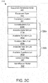
- FIG. 2C is a schematic block diagram of the equipment data 215.
- the equipment data 215 may describe one or more equipment privileges 230 for an equipment instance 160.
- the equipment data 215 may be organized as a data structure in a memory.
- the equipment data 215 includes an equipment reference code 205, an equipment type 225, an equipment location 291, and a plurality of equipment privileges 230.
- each equipment privilege 230 may include an available menu list 270. an available data set list 275, and an available functions list 280.
- the equipment data 215 includes a component map 287 and an identification vector 423.
- the equipment panel data 437 may record relationships between equipment instances of an equipment panel.
- the equipment panel data 437 may describe physical and logical locations for each equipment instance 160.
- Each function log 283 may record each function 281 that is employed by the user.
- the function log 283 may include the user identifier 220 for the user and a timestamp.
- Figure 3A is a front view drawing of an equipment panel 300.
- the equipment panel 300 may be disposed in an environment such as an industrial facility.
- the equipment panel 300 may be an equipment instance 160.
- the equipment panel 300 may include a plurality of equipment instances 160.
- Figure 3J is a front view drawing of an electronic device 105 presenting second accessible equipment instances 160b. Some equipment instances 160 that were available as part of the first accessible equipment instances 160a of Figure 3I are not included in the second accessible equipment instances 160b.
- the second accessible equipment instances 160b may be accessed and/or controlled by the user in response to the user having second equipment privileges 230b.
- Figure 3K is a front view drawing of identifying an equipment tag 130 using eye tracking.
- the electronic device 105 identifies a user focus 391 using eye tracking.
- a second camera 135b may track one or more eyes of the user and identify the user focus 391.
- the equipment tag 130 may be identified as the object of the user focus 391.
- the user focus 391 may be determined from at least one of eye tracking, a center of field-of-view, and a center of attention.
- Figure 3L is a front view drawing of identifying and equipment tag using a center a field-of-view 393.
- the user focus 391 is determined to be the center of the field-of-view 393 for the electronic device 105.
- the equipment tag within the center of the field-of-view 393 may be identified as the object of the user focus 391.
- the processor 405 may determine 517 the device location 293 based on the one or more equipment tags 130 within the image 145. In a certain embodiment, the device location 293 is determined 517 based on a given equipment tag 130 within the image 145. The device location 293 may be based on the equipment location 291. In a certain embodiment, the device location 293 is set equal to the equipment location 291 for a first equipment tag 130. The device location 293 may be further modified by triangulating between two or more equipment tags 130 to determine the location of the electronic device 105 relative to the first equipment tag 130.
- the equipment information 150 and/or equipment controls 151 may be presented 555 in proximity to a relevant element of the equipment instance 160.
- an error message equipment information 150 may be presented in proximity to a component of the equipment instance 160 that is generating the error message.
- the method 600 starts, and in one embodiment, the processor 405 identifies 605 an element associated with an equipment instance 160.
- the element may be one of a menu 271, a data set 277, and a function 281.
- the processor 405 further determine 610 if the equipment privilege 230 associated with the element in the equipment data 215 is included in and/or matches the equipment privileges 230 associated with the equipment type 225 for the equipment instance 160 in the credential data 255. If the equipment privilege 230 associated with the element in the equipment data 215 does not match the equipment privileges 230 associated with the equipment type 225 for the equipment instance 160 in the credential data 255, the processor 405 determine 625 if all elements have been tested.
- the equipment instance 160 may be physically accessible to many users, including unauthorized and/or untrained users. Because it is undesirable and dangerous for unauthorized users to employ the equipment instance 160, it is vital that only authorized and trained users with the proper credentials are able to fully utilize the equipment information 150 and/or equipment controls 151. In addition, some equipment information 150 should not be made available to unauthorized users.
- the embodiments described herein restrict access to the equipment information 150 and/or equipment controls 151 by employing the equipment tag 130 to determine the equipment privileges 230 for a user. As a result, only the proper equipment information 150 and/or equipment controls 151 are enabled and presented for the user, so that untrained and/or unauthorized users do not misuse the equipment information 150 and/or equipment controls 151.
Landscapes
- Engineering & Computer Science (AREA)
- Physics & Mathematics (AREA)
- Business, Economics & Management (AREA)
- Theoretical Computer Science (AREA)
- General Physics & Mathematics (AREA)
- Health & Medical Sciences (AREA)
- Economics (AREA)
- Toxicology (AREA)
- General Health & Medical Sciences (AREA)
- Artificial Intelligence (AREA)
- Electromagnetism (AREA)
- Computer Vision & Pattern Recognition (AREA)
- Strategic Management (AREA)
- Tourism & Hospitality (AREA)
- Human Resources & Organizations (AREA)
- Marketing (AREA)
- General Business, Economics & Management (AREA)
- Operations Research (AREA)
- Development Economics (AREA)
- Quality & Reliability (AREA)
- Entrepreneurship & Innovation (AREA)
- Computer Networks & Wireless Communication (AREA)
- Primary Health Care (AREA)
- Computer Security & Cryptography (AREA)
- Signal Processing (AREA)
- User Interface Of Digital Computer (AREA)
Abstract

Description
- This application claims priority to United States Provisional Patent Application
62/418,514 - The subject matter disclosed herein relates to determining a location based on a tag.
- An electronic device for tag based location is disclosed. The electronic device includes a camera, a display, a processor, and a memory. The camera captures an image. The display presents the image. The memory stores credential data and code executable by the processor. The processor identifies a given equipment tag within the image. The processor further determines a device location based on the given equipment tag. A method and computer program product also perform the functions of the electronic device.
- In order that the advantages of the embodiments of the invention will be readily understood, a more particular description of the embodiments briefly described above will be rendered by reference to specific embodiments that are illustrated in the appended drawings. Understanding that these drawings depict only some embodiments and are not therefore to be considered to be limiting of scope, the embodiments will be described and explained with additional specificity and detail through the use of the accompanying drawings, in which:
-
Figure 1A is a schematic block diagram of equipment information system according to an embodiment; -
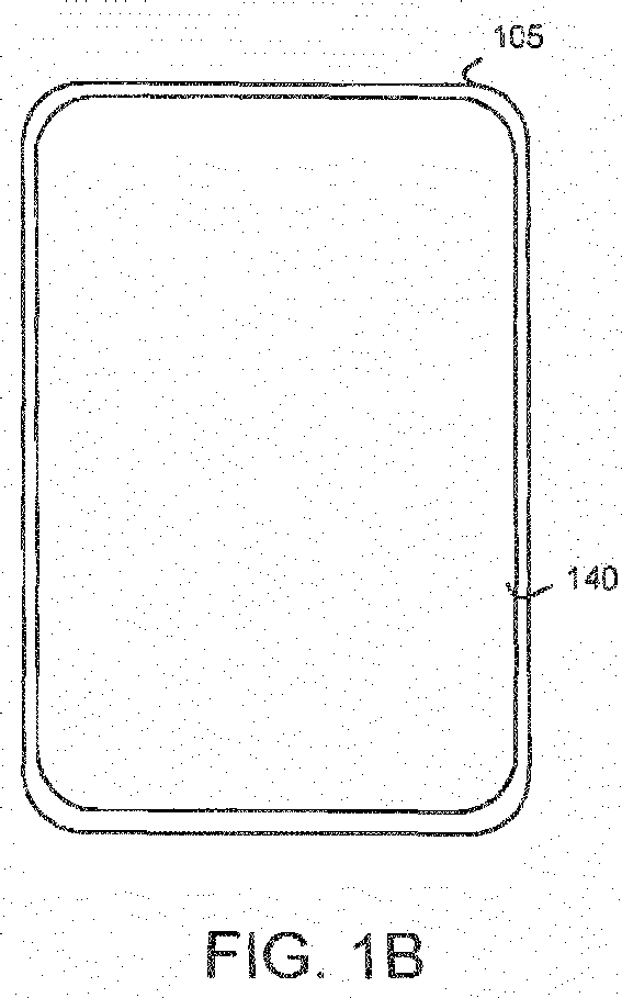
Figure 1B is a front view drawing of a tablet computer according to an embodiment; -
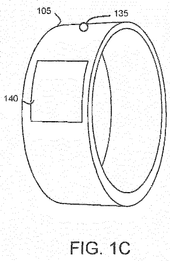
Figure 1C is a perspective drawing of a wearable device according to an embodiment; -
Figure 1D is a perspective drawing of an augmented reality display according to an embodiment; -
Figure 2A is a schematic block diagram of a credential database according to an embodiment: -
Figure 2B is a schematic block diagram of an equipment database according to an embodiment; -
Figure 2C is a schematic block diagram of equipment data according to an embodiment; -
Figure 2D is a schematic block diagram of credential data according to an embodiment; -
Figure 2E is a schematic block diagram of system data according to an embodiment; -
Figure 2F is a schematic block diagram of an available menu list according to an embodiment; -
Figure 2G is a schematic block diagram of an available data set list according to an embodiment; -
Figure 2H is a schematic block diagram of an available functions list according to an embodiment; -
Figure 3A is a front view drawing of an equipment panel according to an embodiment; -
Figure 3B is a front view drawing of an electronic device presenting an equipment instance according to an embodiment; -
Figure 3C is a front view drawing of an electronic device presenting a menu according to an embodiment; -
Figure 3D is a front view drawing of an electronic device presenting a menu according to an alternate embodiment; -
Figure 3E is a front view drawing of an electronic device presenting available functions according to an embodiment; -
Figure 3F is a front view drawing of an electronic device presenting available functions according to an alternate embodiment; -
Figure 3G is a front view drawing of an electronic device presenting available data sets according to an embodiment; -
Figure 3H is a front view drawing of an electronic device presenting available data sets according to an alternate embodiment: -
Figure 3I is a front view drawing of an electronic device presenting accessible equipment instances according to an embodiment; -
Figure 3J is a front view drawing of an electronic device presenting accessible equipment instances according to an alternate embodiment; -
Figure 3K is a front view drawing of identifying an equipment tag using eye tracking according to an embodiment; -
Figure 3L is a front view drawing of identifying and equipment tag using center a field-of-view according to an embodiment; -
Figure 3M is a perspective view drawing of an equipment tag according to an embodiment; -
Figure 4 is a schematic block diagram of the computer according to an embodiment; -
Figure 5A is a schematic flowchart diagram of a device location method according to an embodiment; and -
Figure 5B is a schematic flowchart diagram of a privilege determination method according to an embodiment. - Reference throughout this specification to "one embodiment," "an embodiment," or similar language means that a particular feature, structure, or characteristic described in connection with the embodiment is included in at least one embodiment. Thus, appearances of the phrases "in one embodiment," "in an embodiment," and similar language throughout this specification may, but do not necessarily, all refer to the same embodiment, but mean "one or more but not all embodiments" unless expressly specified otherwise. The terms "including," "comprising," "having," and variations thereof mean "including but not limited to" unless expressly specified otherwise. An enumerated listing of items does not imply that any or all of the items are mutually exclusive and/or mutually inclusive, unless expressly specified otherwise. The terms "a," "an," and "the" also refer to "one or more" unless expressly specified otherwise.
- Furthermore, the described features, advantages, and characteristics of the embodiments may be combined in any suitable manner. One skilled in the relevant art will recognize that the embodiments may be practiced without one or more of the specific features or advantages of a particular embodiment. In other instances, additional features and advantages may be recognized in certain embodiments that may not be present in all embodiments.
- These features and advantages of the embodiments will become more fully apparent from the following description and appended claims, or may be learned by the practice of embodiments as set forth hereinafter. As will be appreciated by one skilled in the art, aspects of the present invention may be embodied as a system, method, and/or computer program product. Accordingly, aspects of the present invention may take the form of an entirely hardware embodiment, an entirely software embodiment (including firmware, resident software, micro-code, etc.) or an embodiment combining software and hardware aspects that may all generally be referred to herein as a "circuit," "module." or "system." Furthermore, aspects of the present invention may take the form of a computer program product embodied in one or more computer readable medium(s) having program code embodied thereon.
- Many of the functional units described in this specification have been labeled as modules, in order to more particularly emphasize their implementation independence. For example, a module may be implemented as a hardware circuit comprising custom VLSI circuits or gate arrays, off-the-shelf semiconductors such as logic chips, transistors, or other discrete components. A module may also be implemented in programmable hardware devices such as field programmable gate arrays, programmable array logic, programmable logic devices or the like.
- Modules may also be implemented in software for execution by various types of processors. An identified module of program code may, for instance, comprise one or more physical or logical blocks of computer instructions which may, for instance, be organized as an object, procedure, or function. Nevertheless, the executables of an identified module need not be physically located together, but may comprise disparate instructions stored in different locations which, when joined logically together, comprise the module and achieve the stated purpose for the module.
- Indeed, a module of program code may be a single instruction, or many instructions, and may even be distributed over several different code segments, among different programs, and across several memory devices. Similarly, operational data may be identified and illustrated herein within modules, and may be embodied in any suitable form and organized within any suitable type of data structure. The operational data may be collected as a single data set, or may be distributed over different locations including over different storage devices, and may exist, at least partially, merely as electronic signals on a system or network. Where a module or portions of a module are implemented in software, the program code may be stored and/or propagated on in one or more computer readable medium(s).
- The computer readable medium may be a tangible computer readable storage medium storing the program code. The computer readable storage medium may be, for example, but not limited to, an electronic, magnetic, optical, electromagnetic, infrared, holographic, micromechanical, or semiconductor system, apparatus, or device, or any suitable combination of the foregoing.
- More specific examples of the computer readable storage medium may include but are not limited to a portable computer diskette, a hard disk, a random access memory (RAM), a read-only memory (ROM), an erasable programmable read-only memory (EPROM or Flash memory), a portable compact disc read-only memory (CD-ROM), a digital versatile disc (DVD), an optical storage device, a magnetic storage device, a holographic storage medium, a micromechanical storage device, or any suitable combination of the foregoing. In the context of this document, a computer readable storage medium may be any tangible medium that can contain, and/or store program code for use by and/or in connection with an instruction execution system, apparatus, or device.
- The computer readable medium may also be a computer readable signal medium. A computer readable signal medium may include a propagated data signal with program code embodied therein, for example, in baseband or as part of a carrier wave. Such a propagated signal may take any of a variety of forms, including, but not limited to, electrical, electro-magnetic, magnetic, optical, or any suitable combination thereof A computer readable signal medium may be any computer readable medium that is not a computer readable storage medium and that can communicate, propagate, or transport program code for use by or in connection with an instruction execution system, apparatus, or device. Program code embodied on a computer readable signal medium may be transmitted using any appropriate medium, including but not limited to wire-line, optical fiber, Radio Frequency (RF), or the like, or any suitable combination of the foregoing
- In one embodiment, the computer readable medium may comprise a combination of one or more computer readable storage mediums and one or more computer readable signal mediums. For example, program code may be both propagated as an electro-magnetic signal through a fiber optic cable for execution by a processor and stored on RAM storage device for execution by the processor.
- Program code for carrying out operations for aspects of the present invention may be written in any combination of one or more programming languages, including an object-oriented programming language such as Java, Smalltalk, C++, C#, PHP or the like and conventional procedural programming languages, such as the "C" programming language or similar programming languages. The program code may execute entirely on the user's computer, partly on the user's computer, as a stand-alone software package, partly on the user's computer and partly on a remote computer or entirely on the remote computer or server. In the latter scenario, the remote computer may be connected to the user's computer through any type of network, including a local area network (LAN) or a wide area network (WAN), or the connection may be made to an external computer (for example, through the Internet using an Internet Service Provider). The computer program product may be shared, simultaneously serving multiple customers in a flexible, automated fashion.
- The computer program product may be integrated into a client, server and network environment by providing for the computer program product to coexist with applications, operating systems and network operating systems software and then installing the computer program product on the clients and servers in the environment where the computer program product will function. In one embodiment software is identified on the clients and servers including the network operating system where the computer program product will be deployed that are required by the computer program product or that work in conjunction with the computer program product. This includes the network operating system that is software that enhances a basic operating system by adding networking features.
- Furthermore, the described features, structures, or characteristics of the embodiments may be combined in any suitable manner. In the following description, numerous specific details are provided, such as examples of programming, software modules, user selections, network transactions, database queries, database structures, hardware modules, hardware circuits, hardware chips, etc., to provide a thorough understanding of embodiments. One skilled in the relevant art will recognize, however, that embodiments may be practiced without one or more of the specific details, or with other methods, components, materials, and so forth. In other instances, well-known structures, materials, or operations are not shown or described in detail to avoid obscuring aspects of an embodiment.
- Aspects of the embodiments are described below with reference to schematic flowchart diagrams and/or schematic block diagrams of methods, apparatuses, systems, and computer program products according to embodiments of the invention. It will be understood that each block of the schematic flowchart diagrams and/or schematic block diagrams, and combinations of blocks in the schematic flowchart diagrams and/or schematic block diagrams, can be implemented by program code. The program code may be provided to a processor of a general-purpose computer, special purpose computer, sequencer, or other programmable data processing apparatus to produce a machine, such that the instructions, which execute via the processor of the computer or other programmable data processing apparatus, create means for implementing the functions/acts specified in the schematic flowchart diagrams and/or schematic block diagrams block or blocks.
- The program code may also be stored in a computer readable medium that can direct a computer, other programmable data processing apparatus, or other devices to function in a particular manner, such that the instructions stored in the computer readable medium produce an article of manufacture including instructions which implement the function/act specified in the schematic flowchart diagrams and/or schematic block diagrams block or blocks.
- The program code may also be loaded onto a computer, other programmable data processing apparatus, or other devices to cause a series of operational steps to be performed on the computer, other programmable apparatus or other devices to produce a computer implemented process such that the program code which executed on the computer or other programmable apparatus provide processes for implementing the functions/acts specified in the flowchart and/or block diagram block or blocks.
- The schematic flowchart diagrams and/or schematic block diagrams in the Figures illustrate the architecture, functionality, and operation of possible implementations of apparatuses, systems, methods and computer program products according to various embodiments of the present invention. In this regard, each block in the schematic flowchart diagrams and/or schematic block diagrams may represent a module, segment, or portion of code, which comprises one or more executable instructions of the program code for implementing the specified logical function(s).
- It should also be noted that, in some alternative implementations, the functions noted in the block may occur out of the order noted in the Figures. For example, two blocks shown in succession may, in fact, be executed substantially concurrently, or the blocks may sometimes be executed in the reverse order, depending upon the functionality involved. Other steps and methods may be conceived that are equivalent in function, logic, or effect to one or more blocks, or portions thereof, of the illustrated Figures.
- Although various arrow types and line types may be employed in the flowchart and/or block diagrams, they are understood not to limit the scope of the corresponding embodiments. Indeed, some arrows or other connectors may be used to indicate only the logical flow of the depicted embodiment. For instance, an arrow may indicate a waiting or monitoring period of unspecified duration between enumerated steps of the depicted embodiment. It will also be noted that each block of the block diagrams and/or flowchart diagrams, and combinations of blocks in the block diagrams and/or flowchart diagrams, can be implemented by special purpose hardware-based systems that perform the specified functions or acts, or combinations of special purpose hardware and program code.
- The description of elements in each figure may refer to elements of proceeding figures. Like numbers refer to like elements in all figures, including alternate embodiments of like elements.
-
Figure 1A is a schematic block diagram ofequipment information system 100. Theequipment information system 100 may locate anelectronic device 105 and manage the presentation ofequipment information 150 at anequipment instance 160. In the depicted embodiment, thesystem 100 includes aserver 120, anetwork 115, anelectronic device 105, and theequipment instance 160. - The
equipment instance 160 may be an industrial controller, a motor drive, and the like. Thenetwork 115 may be the Internet, a wide-area network, a local area network, a mobile telephone network, a Wi-Fi network, or combinations thereof. Theelectronic device 105 may be selected from the group consisting of an augmented-reality display, a computer tablet, a watch, a wearable device, and a mobile telephone. In one embodiment, the augmented-reality display is worn over the eyes of the user and displays both physical objects in the user's field-of-view and virtual objects such as virtual controls. Theelectronic device 105 may store credential data for a user of theelectronic device 105. - The
server 120 may store one or more databases that are used by theelectronic device 105. Theserver 120 and theelectronic device 105 may communicate through thenetwork 115. - The
equipment instance 160 may include equipment controls 151. The equipment controls 151 may control theequipment instance 160. In addition, the equipment controls 151 may present theequipment information 150. In addition, the equipment controls 151 may be modified by theequipment information 150. The equipment controls 151 may include one or more of a touchscreen display, a keyboard, a pointing device, discrete buttons, discrete switches, discrete knobs and the like. The equipment controls 151 may express and/or be modified by theequipment information 150. - The
electronic device 105 may include acamera 135 and adisplay 140. Thecamera 135 may capture animage 145 of theequipment instance 160 and anequipment tag 130 disposed on theequipment instance 160. Theequipment tag 130 may be selected from the group consisting of a two-dimensional optical code, a Quick Response (QR) code, a bar code, a Universal Product Code (UPC), a BLUETOOTH® Low Energy (BLE) Tag, a Radio Frequency Identifier (RFID), a Near Field Communication (NFC) tag, and a Europay. Mastercard, Visa (EMV) tag. In one embodiment, two or more types ofequipment tag 130 may be employed concurrently. In one embodiment, theequipment tag 130 in codes and equipment reference code. - The
system 100 may be used in a facility such as an industrial environment with the plurality ofequipment instances 160. In addition, many of theequipment instances 160 may appear to be similar and/or identical. As a result, it may be difficult for a user to locate herself in the industrial facility by using theequipment instances 160 as landmarks. The embodiments described herein determine a device location of theelectronic device 105 based onequipment tag 130, allowing the user of theelectronic device 105 to determine her position within the facility. - The equipment controls 151 are available to all users with physical access to the
equipment instance 160. Unfortunately, not all potential users may have the necessary credentials to employ all of theequipment information 150 and/or the equipment controls 151. The embodiments described herein determine equipment privileges for theequipment instance 160 as a function of an equipment type and the credential data. The embodiments further present theequipment information 150 and/or equipment controls 151 that are enabled by the equipment privileges to the user. As a result, the user is only given access to theequipment information 150 that are within the scope of his credential data, preventing unauthorized and/or unqualified users from accessing some or allequipment information 150. -
Figure 1B is a front view drawing of a tablet computerelectronic device 105. The tablet computerelectronic device 105 includes adisplay 140 and a camera 135 (not shown). In addition, the tablet computerelectronic device 105 includes the computer. -
Figure 1C is a perspective drawing of a wearable deviceelectronic device 105. The wearable deviceelectronic device 105 is shown as a watch and/or bracelet. The wearable deviceelectronic device 105 includes adisplay 140 and acamera 135. In one embodiment, the wearable deviceelectronic device 105 includes a computer. -
Figure 1D is a perspective drawing of an augmented reality displayelectronic device 105. In one embodiment, the augmented-reality display is worn over the eyes of the user and displays both physical objects in the user's field-of-view that are captured by acamera 135 and virtual objects such as virtual controls on an internal display (not shown). In one embodiment, the augmented reality displayelectronic device 105 includes a computer. -
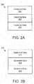
Figure 2A is a schematic block diagram of acredential database 200. Thecredential database 200 may be organized as a data structure in a memory such as the memory of theserver 120 and/or theelectronic device 105. Thecredential database 200 may include a plurality ofcredential data 255 that will be described hereafter inFigure 2D . -
Figure 2B is a schematic block diagram of anequipment database 210. Theequipment database 210 may be organized as a data structure in a memory such as the memory of theserver 120 and/or theelectronic device 105. Theequipment database 210 may include a plurality ofequipment data 215 that will be described hereafter inFigure 2C . -
Figure 2C is a schematic block diagram of theequipment data 215. Theequipment data 215 may describe one or more equipment privileges 230 for anequipment instance 160. Theequipment data 215 may be organized as a data structure in a memory. In the depicted embodiment, theequipment data 215 includes anequipment reference code 205, anequipment type 225, anequipment location 291, and a plurality of equipment privileges 230. In addition, each equipment privilege 230 may include anavailable menu list 270. an availabledata set list 275, and an available functions list 280. In one embodiment, theequipment data 215 includes acomponent map 287 and anidentification vector 423. - The
equipment reference code 205 may uniquely identify asingle equipment instance 160. In one embodiment, theequipment reference code 205 is a serial number. Alternatively, theequipment reference code 205 may uniquely identify a group ofequipment instances 160 and theequipment reference code 205 may include a model number. Theequipment reference code 205 may be encoded in anequipment tag 130. Theequipment reference code 205 andcorresponding equipment instance 160 may be identified from theequipment tag 130. - The
equipment type 225 may identify a type ofequipment instances 160. In one embodiment, the type is a singleunique equipment instance 160 such a controller. Alternatively, the type may be a specific model of theequipment instance 160. Theequipment type 225 may represent the features and functionality of theequipment instance 160. Theequipment type 225 may be used to determine whatequipment privileges 230 a given user has for theequipment instance 160. In one embodiment, the equipment privileges 230 for a givenequipment type 225 are standardized as a function of user training, experience, and authorizations. For example, a user may be required to complete specified training, have a specified number of hours using a feature and/or function of anequipment instance 160, and/or have appropriate authorizations in order to have a specified equipment privilege 230. - Each equipment privilege 230 may define a coherent group of menus, display data, and functions that are enabled as
equipment information 150 at the equipment controls 151 and/or at theelectronic device 105. The equipment privileges 230 may be organized so that different sets of menus, data, and functions are enabled for users withdifferent credential data 255. Theavailable menu list 270 may include one or more menus that are enabled at theequipment information 150. The available data setlist 275 may include one or more data sets that may be displayed by theequipment information 150. The available functions list 280 may include one or more functions of theequipment information 150 that are enabled at the equipment controls 151. For example, both a firstavailable functions list 280a and a secondavailable functions list 280b may include an emergency shutdown function. However, only the first available functions list 280a may enable a diagnostic test function. - The
component map 287 may comprise a visual map locating components of theequipment instance 160. Thecomponent map 287 may comprise a plurality of elevations. Each elevation may comprise one or more components. - The
identification vector 423 may encode a location of theequipment tag 130 as a vector comprising a plurality of elements. In one embodiment, the vector is a binary vector wherein each element is a binary value. Theidentification vector 423 may be manipulated with a facility vector in order to determine a location of theelectronic device 105. The manipulation of theidentification vector 423 with the facility vector greatly accelerates locating theequipment instance 160 within a facility. As a result, theelectronic device 105 is rapidly identified and located. -
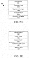
Figure 2D is a schematic block diagram of thecredential data 255. Thecredential data 255 may identify equipment privileges 230 for a user. Thecredential data 255 may be organized as a data structure in a memory. In the depicted embodiment, thecredential data 255 includes a user identifier 220, one ormore equipment types 225, and one or more corresponding equipment privileges 230. - The user identifier 220 may uniquely identify the user of the
electronic device 105. In one embodiment, the user identifier 220 includes one or more biometric credentials for the user including an image, a fingerprint, a voice print, a retinal scan, and the like. In addition, the user identifier 220 may include an identifying alphanumeric string and/or a password. - Each
equipment type 225 may identify a type ofequipment instance 160. The equipment privileges 230 corresponding to theequipment type 225 may specify whichequipment information 150 and/or equipment controls 151 are enabled for the user. -
Figure 2E is a schematic block diagram of system data. The system data may be organized as a data structure in a memory. In the depicted embodiment, the system data includes adevice location 293, thefacility vector 431, alocation vector 435,equipment panel data 437, and a location table 439. - The
device location 293 may locate theelectronic device 105. Thedevice location 293 may be determined from theequipment location 291. The device location 425 may be set equal to anequipment location 291. In addition, thedevice location 293 may be modified from theequipment location 291. For example, thedevice location 293 may be estimated from a combination of theequipment location 291 and a view of theequipment tag 130 and/orcorresponding equipment instance 160. In one embodiment, thedevice location 293 includes an orientation of theelectronic device 105. In addition, thedevice location 293 may include an orientation of the user. - The
facility vector 431 may be a vector that is encoded such that when manipulated along with theidentification vector 423, a location of theequipment tag 130 and/or theelectronic device 105 may be rapidly determined. In one embodiment, thelocation vector 435 is calculated as a function of theidentification vector 423 and thefacility vector 431. Thelocation vector 435 may be a vector description of thedevice location 293 and/or theequipment location 291. Thelocation vector LV 435 may be calculated using Equation 1, where IV is theidentification vector 423 and FV is thefacility vector 431.
- The
location vector 435 may identify the location of theequipment tag 130 and/orelectronic device 105. The location table 439 may include entries for a plurality of locations indexed bylocation vectors 435. In one embodiment, thelocation vector 435 is used as an index to the location table 439 to identify the location of theequipment tag 130,equipment instance 160, and/orelectronic device 105. - The
equipment panel data 437 may record relationships between equipment instances of an equipment panel. For example, theequipment panel data 437 may describe physical and logical locations for eachequipment instance 160. -
Figure 2F is a schematic block diagram of theavailable menu list 270 ofFigure 2C . Theavailable menu list 270 maybe organized as a data structure in a memory. In the depicted embodiment, theavailable memory list 270 includes a plurality of menu list entries 272. Each menu list entry 272 includes a menu 271, a corresponding equipment privilege 230, and a menu log 273. - Each
menu 271a-c may include a plurality of options that may be selected by a user. Some options may be common to two or more menus 271. In addition, some options may be exclusive to one menu 271 Eachmenu 271a-c may be associated withdifferent equipment privileges 230a-c. For example, afirst menu 271a may only be available if the user possessesfirst equipment privileges 230a. In addition, if the user docs not possessfirst equipment privileges 230a, but does possesssecond equipment privileges 230b, thesecond menu 271b may be available for the user. - The menu log 273 may record each instance that a menu 271 was made available to the user. The menu log 273 may include the user identifier 220 for the user and a timestamp. In one embodiment, the memory log 273 records each selection of the menu 271 made by the user.
-
Figure 2G is a schematic block diagram of an availabledata set list 275 ofFigure 2C . The available data setlist 275 may be organized as a data structure in a memory. In the depicted embodiment, the available data setlist 275 includes a plurality of data set list entries 276. Each data set entry 276 includes a data set 277, a corresponding equipment privilege 230, and a data set log 279. - Each data set 277a-c may include a plurality of data instances. Some data instances may be common to two or more data sets 277. In addition, some data instances may be exclusive to one data set 277. Each data set 277a-c may be associated with
different equipment privileges 230a-c. Afirst data set 277a may be available to a user withfirst equipment privileges 230a while asecond data set 277b may be available to the user withsecond equipment privileges 230b. - Each data set log 279 may record each data instance of the data set 277 that is accessed by the user. The data set log 279 may include the user identifier 220 for the user and a timestamp.
-
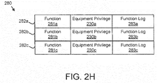
Figure 2H is a schematic block diagram of an available functions list 280 ofFigure 2C . The available functions list 280 maybe organized as a data structure in a memory. In the depicted embodiment, the available functions list 280 includes a plurality of function entries 282. Each function entry 282 includes a function 281, a corresponding equipment privilege 230, and a function log 283. - Each function 281 may be a function of the
equipment instance 160. In one embodiment, a function is the ability to access anequipment instance 160. In addition, a function may initiate an action by theequipment instance 160. Eachfunction 281a-c may be associated withdifferent equipment privileges 230a-c. Afirst function 281a may be available to the user withfirst equipment privileges 230a while asecond function 281b may be available to the user withsecond equipment privileges 230b. - Each function log 283 may record each function 281 that is employed by the user. The function log 283 may include the user identifier 220 for the user and a timestamp.
-
Figure 3A is a front view drawing of anequipment panel 300. Theequipment panel 300 may be disposed in an environment such as an industrial facility. Theequipment panel 300 may be anequipment instance 160. In addition, theequipment panel 300 may include a plurality ofequipment instances 160. - Equipment tags 130 may be disposed on one or
more equipment instances 160. In one embodiment, thecamera 135 captures animage 145 of theequipment panel 300. Theelectronic device 105 may identify a givenequipment tag 130 within theimage 145. -
Figure 3B is a front view drawing of anelectronic device 105 displaying anequipment panel 300. For simplicity, thedisplay 140 of the tablet computerelectronic device 105 is shown. However, thedisplay 140 of the wearable deviceelectronic device 105 and the augmented reality displayelectronic device 140 may also be employed. Thecamera 135 may capture animage 145 of one ormore equipment instances 160 and corresponding equipment tags 130. Theelectronic device 105 may identify the equipment tags 130 in theimage 145. Theelectronic device 105 may further identify a givenequipment tag 130. - A processor may further emphasize the given
equipment instance 160b presented in thedisplay 140. In the depicted embodiment, the givenequipment instance 160b is highlighted in thedisplay 140. The highlighting may increase the perceived luminescence of the givenequipment instance 160b. Alternatively, the highlighting may decrease the perceived luminescence of the givenequipment instance 160b. In one embodiment, the highlighting may modify a color of the givenequipment instance 160b. - The given
equipment instance 160b may also be one or more of modulated, outlined, and annotated in thedisplay 140. For example, the givenequipment instance 160b may be modulated between increased luminescence and decreased luminescence. In addition, the givenequipment instance 160 may be modulated between a first color and a second color. The givenequipment instance 160 may be outlined with the border of increased luminescence, decreased luminescence, a modified color, a specified color such as red or white, and the like. In one embodiment, the givenequipment instance 160b is annotated with a label. In addition,other equipment instances 160 around the givenequipment instance 160b may be obscured and/or not displayed as shown in the depicted embodiment. -
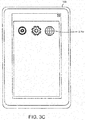
Figure 3C is a front view drawing of anelectronic device 105 presenting afirst menu 271a. In the depicted embodiment, thefirst menu 271a includes a first set of three options, Thefirst menu 271a may be associated withfirst equipment privileges 230a. Thus, if a user has thefirst equipment privileges 230a, the user may access thefirst menu 271a and thefirst menu 271a is an available menu for the user. Thefirst menu 271a may be presented to the user as theequipment information 150 and/or equipment controls 151. Thefirst menu 271a may be presented as the equipment controls 151 of theequipment instance 160. -
Figure 3D is a front view drawing of anelectronic device 105 presenting asecond menu 271b. In the depicted embodiment, thesecond menu 271b includes a second set of two options. The two options are common to thefirst menu 271a ofFigure 3C . However, the options do not include a third option of thefirst menu 271a. Thesecond menu 271b may be associated withsecond equipment privileges 230b. If the user has thesecond equipment privileges 230b but not thefirst equipment privileges 230a, thesecond menu 271b may be presented to the user as theequipment information 150 and/or equipment controls 151 on theequipment instance 160. Thesecond menu 271b may be an available menu for the user. -
Figure 3E is a front view drawing of anelectronic device 105 presenting available functions 281. In the depicted embodiment, the firstavailable functions 281a are presented to the user. In one embodiment, the firstavailable functions 281a are presented as equipment controls 151 on theequipment instance 160. In addition, thefirst functions 281a may be included asequipment information 150. Thefirst functions 281a may be available to the user if the user has thefirst equipment privileges 230a. -
Figure 3F is a front view drawing of anelectronic device 105 presenting secondavailable functions 281b. In the depicted embodiment, secondavailable functions 281b are presented to the user. Some of the firstavailable functions 281a ofFigure 3E are not included in the secondavailable functions 281b. The secondavailable functions 281b may be available to the user if the user has thesecond equipment privileges 230b. -
Figure 3G is a front view drawing of anelectronic device 105 presenting available data sets 277. In the depicted embodiment, a first available data set 277a comprising threedata set instances 315a-c are presented. Thefirst data set 277a may be presented in response to the user havingfirst equipment privileges 230a corresponding to thefirst data set 277a. In one embodiment, the user may access eachdata set instance 315a-c of thefirst data set 277a. In a certain embodiment, thefirst data set 277a is presented as equipment controls 151. -
Figure 3H is a front view drawing of anelectronic device 105 presenting a second available data set 277b. In the depicted embodiment, the second available data set 277b is presented to the user in response to the user havingsecond equipment privileges 230b that correspond to thesecond data set 277b. Thesecond data set 277b does not include the thirddata set instance 315c of thefirst data set 277a. -
Figure 3I is a front view drawing of anelectronic device 105 presentingaccessible equipment instances 160. In the depicted embodiment, firstaccessible equipment instances 160a are presented to the user. The firstaccessible equipment instances 160a may be accessed and/or controlled by the user in response to the user havingfirst equipment privileges 230a. In one embodiment, the firstaccessible equipment instances 160a are presented as equipment controls 151. -
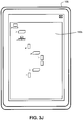
Figure 3J is a front view drawing of anelectronic device 105 presenting secondaccessible equipment instances 160b. Someequipment instances 160 that were available as part of the firstaccessible equipment instances 160a ofFigure 3I are not included in the secondaccessible equipment instances 160b. The secondaccessible equipment instances 160b may be accessed and/or controlled by the user in response to the user havingsecond equipment privileges 230b. -
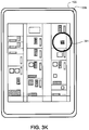
Figure 3K is a front view drawing of identifying anequipment tag 130 using eye tracking. In the depicted embodiment, theelectronic device 105 identifies auser focus 391 using eye tracking. Asecond camera 135b may track one or more eyes of the user and identify theuser focus 391. Theequipment tag 130 may be identified as the object of theuser focus 391. Theuser focus 391 may be determined from at least one of eye tracking, a center of field-of-view, and a center of attention. -
Figure 3L is a front view drawing of identifying and equipment tag using a center a field-of-view 393. In the depicted embodiment, theuser focus 391 is determined to be the center of the field-of-view 393 for theelectronic device 105. The equipment tag within the center of the field-of-view 393 may be identified as the object of theuser focus 391. - In one embodiment, the center of attention is determined to correspond to a mathematical mode of a plurality of locations of the
user focus 391. Alternatively, the center of attention may be determined to correspond to a mathematical mode of a plurality of locations of the center of the field-of-view 393. The center of attention may be calculated using Equations 2 and 3, wherein CAx is the horizontal coordinate within thedisplay 140 of the center of attention, CAy is the vertical coordinate within thedisplay 140 of the center of attention, n is a number of user focusinstances 391, and i is an index to the user focusinstances 391.

-
Figure 3M is a perspective view drawing of anequipment tag 130. In the depicted embodiment, theequipment tag 130 is a QR code that is viewed by thecamera 135 at an angle and from a distance. Theequipment tag 130 has a perceivedarea 133. In addition, theequipment tag 130 has perceivededges 131, and each perceivededge 131 has a perceived length and a perceived angle relative to thecamera 135. -
Figure 4 is a schematic block diagram of thecomputer 400. Thecomputer 400 may be embodied in theelectronic device 105. In addition, thecomputer 400 may be embodied in theserver 120. In one embodiment, thecomputer 400 is embodied in theequipment instance 160. In the depicted embodiment, thecomputer 400 includes aprocessor 405, amemory 410, andcommunication hardware 415. Thememory 410 may include a semiconductor storage device, an optical storage device, a hard disk drive, a micromechanical storage device, or combinations thereof. Thememory 410 may store code. Theprocessor 405 may execute the code. Thecommunication hardware 415 may communicate with other devices and/or thenetwork 115. -
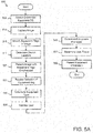
Figure 5A is a schematic flowchart diagram of adevice location method 500. Themethod 500 may locate anelectronic device 105 based on theequipment tag 130. In addition, themethod 500 may determine equipment privileges 230 based on theequipment type 225 and thecredential data 255 andpresent equipment information 150 and/or equipment controls 151 enabled by the equipment privileges 230. Themethod 500 may be performed by thecamera 135 and thecomputer 400 and/orprocessor 405 of one or more of theelectronic device 105, theserver 120, and theequipment instance 160. - The
method 500 starts, and in one embodiment, theprocessor 405 accesses 505 thecredential database 200 and theequipment database 210. In one embodiment, theprocessor 405 synchronizes thecredential database 200 and/or theequipment database 210 from theserver 120 to theelectronic device 105. Alternatively, theprocessor 405 establishes a link to thecredential database 200 and/or theequipment database 210 stored on theserver 120. - The
camera 135 may capture 510 theimage 145 of theequipment instance 160. In one embodiment, thecamera 135 continuously captures 510images 145 as a video stream. Alternatively, thecamera 135 may capture 510 theimage 145 in response to a user command. In one embodiment, thecamera 135 may capture 510 theimage 145 in response to auser focus 391 on anequipment tag 130 and/or on anequipment instance 160. - The
processor 405 may further identify 515 one ormore equipment tags 130 within theimage 145. In one embodiment, theprocessor 405 parses theequipment reference code 205 from eachequipment tag 130 to identify the equipment tags 130 and/or thecorresponding equipment instances 160. - The
processor 405 may determine 517 thedevice location 293 based on the one ormore equipment tags 130 within theimage 145. In a certain embodiment, thedevice location 293 is determined 517 based on a givenequipment tag 130 within theimage 145. Thedevice location 293 may be based on theequipment location 291. In a certain embodiment, thedevice location 293 is set equal to theequipment location 291 for afirst equipment tag 130. Thedevice location 293 may be further modified by triangulating between two ormore equipment tags 130 to determine the location of theelectronic device 105 relative to thefirst equipment tag 130. - In one embodiment, the
processor 405 determines an orientation of theelectronic device 105 relative to theequipment tag 130 as a function of the perceivededges 131 of theequipment tag 130. In addition, theprocessor 405 may determine a distance to theequipment tag 130 based on the perceivedsize 133 of theequipment tag 130. Theprocessor 405 may determine thedevice location DL 293 as shown in Equation 4, wherein MO is an orientation matrix of theelectronic device 105, EL is theequipment location 291, and D is a distance from theelectronic device 105 to theequipment tag 130.
- In one embodiment, the
device location 293 is determined using theidentification vector 423 to accelerate determining thedevice location 293. - In one embodiment, the
processor 405 presents 520 theimage 145 with the one ormore equipment tags 130 and/or correspondingequipment instances 160 emphasized in thedisplay 140. Emphasized equipment tags 130 and/orequipment instances 160 may be highlighted, modulated, outlined, and/or annotated. - The
processor 405 may receive 525 a selection of anequipment tag 130. A user may make a selection of the givenequipment tag 130 from theuser focus 391 along with a corresponding command. Alternatively, the givenequipment tag 130 may be selected from the center of the field-of-view 393 along with a corresponding command. In one embodiment, a givenequipment tag 130 at the center of attention maybe emphasized and the user may select the emphasized givenequipment tag 130 using a corresponding command. In addition, the user may select a givenequipment tag 130 and/orcorresponding equipment instance 160 by touching the givenequipment tag 130 and/orcorresponding equipment instance 160 on thedisplay 140. In one embodiment, if only oneequipment tag 130 is presented 520, thatequipment tag 130 may be automatically selected. - The
processor 405 may determine 530 the givenequipment type 225 from theequipment tag 130. Theequipment type 225 may be determined 530 for the selectedequipment tag 130. In one embodiment, theequipment reference code 205 is parsed from theequipment tag 130. In addition, theequipment reference code 205 may be parsed from a hash of theequipment tag 130. Theequipment reference code 205 may be used as an index to identify thecorresponding equipment data 215 andequipment type 225 from theequipment database 210. - The
processor 405 may validate 535 the user with thecredential data 255. In one embodiment, theprocessor 405 identifies the user with the alphanumeric string and/or password of the user identifier 220. In addition, theprocessor 405 may validate 535 the user with the biometric credentials of the user identifier 220. In alternative embodiment, theprocessor 405 may identify the user with the biometric credentials and validate the user using the password and/or alphanumeric string of the user identifier 220. - The
processor 405 may determine 545 the equipment privileges 230 for the user based on the equipment type 225 n thecredential data 255 for the user as a function of theequipment type 225 and thecredential data 255. For example, if theequipment instance 160 is of afirst equipment type 225a, the equipment privileges 230 for the user may be the correspondingfirst equipment privileges 230a recorded in thecredential data 255. Thedetermination 545 of the equipment privileges 230 is described in more detail inFigure 5B . - The
processor 405 may determine 550 theuser focus 391 for the user. In addition, theprocessor 405 may present 555 theequipment information 150 and/or equipment controls 151 that are enabled by the equipment privileges 230 and themethod 500 ends. In a certain embodiment, theequipment information 150 and/or equipment controls 151 are only presented when the givenequipment instance 160 corresponding to the givenequipment tag 130 is within a field-of-view of theelectronic device 105. The field-of-view may be thedisplay 140. Alternatively, the field-of-view may be a central portion of thedisplay 140. Theequipment information 150 and/or equipment controls 151 may be presented by theelectronic device 105. In addition, theequipment information 150 and/or equipment controls 151 may be presented by theequipment instance 160. - In one embodiment, presenting 555 the
equipment information 150 comprises presenting one or more available menus 271 from theavailable menus list 270. In addition, presenting 550 theequipment information 150 may comprise presenting one or more available data sets 277 from the availabledata sets list 275. In a certain embodiment, presenting 550 theequipment information 150 may comprise enabling one or more functions 281 from the available functions list 280. The menus 271, data sets 277, and functions 281 may be presented via the equipment controls 151. - In one embodiment, the
equipment information 150 and/or equipment controls 151 are presented 555 based on theuser focus 391. Theequipment information 150 and/or equipment controls 151 may be presented 550 at theuser focus 391. Alternatively, theequipment information 150 and/or equipment controls 151 may be presented 555 as offset from theuser focus 391. In a certain embodiment, theequipment information 150 and/or equipment controls 151 may be presented 555 so as not to obscure the givenequipment instance 160. - In one embodiment, the
equipment information 150 and/or equipment controls 151 may be presented 555 in proximity to a relevant element of theequipment instance 160. For example, an errormessage equipment information 150 may be presented in proximity to a component of theequipment instance 160 that is generating the error message. -
Figure 5B is a schematic flowchart diagram of aprivilege determination method 600. Themethod 600 may determine equipment privileges 230 for anequipment instance 160. Themethod 600 may perform step 545 ofFigure 5A . Themethod 600 may be performed by thecamera 135 and thecomputer 400 and/orprocessor 405 of one or more of theelectronic device 105, theserver 120, and theequipment instance 160. - The
method 600 starts, and in one embodiment, theprocessor 405 identifies 605 an element associated with anequipment instance 160. The element may be one of a menu 271, a data set 277, and a function 281. Theprocessor 405 further determine 610 if the equipment privilege 230 associated with the element in theequipment data 215 is included in and/or matches the equipment privileges 230 associated with theequipment type 225 for theequipment instance 160 in thecredential data 255. If the equipment privilege 230 associated with the element in theequipment data 215 does not match the equipment privileges 230 associated with theequipment type 225 for theequipment instance 160 in thecredential data 255, theprocessor 405 determine 625 if all elements have been tested. - . If the equipment privilege 230 associated with the element in the
equipment data 215 matches the equipment privileges 230 associated with theequipment type 225 for theequipment instance 160 in thecredential data 255, theprocessor 405 enables 615 the element in theequipment information 150 and/or equipment controls 151. As a result, the user may be able to employ the enabled element. - In one embodiment, the processor 450
records 620 that the user is enabled to employ the enabled element in the corresponding log for the element. For example, the menu 271, user identifier 220, and a timestamp may be recorded in the corresponding menu log 273 in response to enabling the menu 271. - The
processor 405 determine 625 if all elements of theequipment instance 160 have been tested. If all elements have not been tested, theprocessor 405 loops to identify 605 another element. If all elements have been tested, themethod 600 ends. - A user and/or her colleagues may be unsure of her location within an industrial facility. The embodiments may locate the user within the industrial facility by determining a
device location 293 forelectronic device 105 based on identifying a givenequipment tag 130 within animage 145 captured by theelectronic device 105. As a result, the user and/or her colleagues can immediately determine her location. - The
equipment instance 160 may be physically accessible to many users, including unauthorized and/or untrained users. Because it is undesirable and dangerous for unauthorized users to employ theequipment instance 160, it is vital that only authorized and trained users with the proper credentials are able to fully utilize theequipment information 150 and/or equipment controls 151. In addition, someequipment information 150 should not be made available to unauthorized users. The embodiments described herein restrict access to theequipment information 150 and/or equipment controls 151 by employing theequipment tag 130 to determine the equipment privileges 230 for a user. As a result, only theproper equipment information 150 and/or equipment controls 151 are enabled and presented for the user, so that untrained and/or unauthorized users do not misuse theequipment information 150 and/or equipment controls 151. - This description uses examples to disclose the invention and also to enable any person skilled in the art to practice the invention, including making and using any devices or systems and performing any incorporated methods. The patentable scope of the invention is defined by the claims and may include other examples that occur to those skilled in the art. Such other examples are intended to be within the scope of the claims if they have structural elements that do not differ from the literal language of the claims, or if they include equivalent structural elements with insubstantial differences from the literal language of the claims.
- The following is a list of further preferred embodiments of the invention:
- Embodiment 1. An electronic device comprising:
- a camera that captures an image;
- a display that presents the image;
- a processor;
- a memory that stores credential data and code executable by the processor to perform:
- identifying a given equipment tag within the image; and
- determining a device location based on the given equipment tag.
- Embodiment 2. The electronic device of embodiment 1, wherein the given equipment tag is identified based on a user focus.
- Embodiment 3. The electronic device of embodiment 2, wherein the user focus is determined from at least one of eye tracking, a center of field-of-view, and a center of attention.
- Embodiment 4. The electronic device of embodiment 2, the processor further presenting equipment information based on a user focus.
- Embodiment 5. The electronic device of embodiment 1, wherein the device location is determined from an equipment location for an equipment instance corresponding to the given equipment tag.
- Embodiment 6. The electronic device of embodiment 5, the processor further determining an orientation of a user relative to the equipment tag.
- Embodiment 7. The electronic device of embodiment 1, the processor further:
- determining a given equipment type from the given equipment tag;
- determining equipment privileges as a function of the given equipment type and the credential data; and
- presenting equipment information that are enabled by the equipment privileges.
- Embodiment 8. The electronic device of embodiment 7, wherein presenting the equipment information comprises presenting one or more of available menus, available data sets, and available functions.
- Embodiment 9. The electronic device of embodiment 7, wherein the equipment information is only presented when the given equipment corresponding to the given equipment tag is in a field-of-view of the electronic device.
- Embodiment 10. The electronic device of embodiment 7, wherein the equipment privileges comprises an available menu list, an available data set list, and an available functions list.
- Embodiment 11. The electronic device of embodiment 7, wherein the processor further validates a user with the credential data.
- Embodiment 12. The electronic device of embodiment 1, wherein the processor further performs:
- presenting the image with the given equipment tags emphasized; and
- receiving a selection of the given equipment tag from the image.
- Embodiment 13. The electronic device of embodiment 1, wherein the equipment tag is selected from the group consisting of a two-dimensional optical code, a Quick Response (QR) code, a bar code, a Universal Product Code (UPC), a BLUETOOTH® Low Energy (BLE) Tag, a Radio Frequency Identifier (RFID), a Near Field Communication (NFC) tag, and a Europay, Mastercard, Visa (EMV) tag.
- Embodiment 14. The electronic device of embodiment 1, wherein the electronic device is selected from the group consisting of an augmented-reality display, a computer tablet, a watch, a wearable device, and a mobile telephone.
- Embodiment 15. A method comprising:
- identifying, by use of a processor, a given equipment tag within an image captured by a camera; and
- determining a device location based on the given equipment tag.
- Embodiment 16. The method of embodiment 15, wherein the given equipment tag is identified based on a user focus.
- Embodiment 17. The method of embodiment 15, wherein the user focus is determined from at least one of eye tracking, a center of field-of-view, and a center of attention.
- Embodiment 18. A computer program product comprising a non-transitory computer readable storage medium storing that code executable by a processor to perform:
- identifying a given equipment tag within an image captured by a camera; and
- determining a device location based on the given equipment tag.
- Embodiment 19. The method of embodiment 15, wherein the given equipment tag is identified based on a user focus.
- Embodiment 20. The method of embodiment 15, wherein the user focus is determined from at least one of eye tracking, a center of field-of-view, and a center of attention.
Claims (15)
- An electronic device comprising:a camera that captures an image;a display that presents the image;a processor;a memory that stores credential data and code executable by the processor to perform:identifying a given equipment tag within the image; anddetermining a device location based on the given equipment tag.
- The electronic device of claim 1, wherein the given equipment tag is identified based on a user focus.
- The electronic device of claim 2, wherein the user focus is determined from at least one of eye tracking, a center of field-of-view, and a center of attention.
- The electronic device of claim 2, the processor further presenting equipment information based on a user focus.
- The electronic device of claim 1, wherein the device location is determined from an equipment location for an equipment instance corresponding to the given equipment tag.
- The electronic device of claim 5, the processor further determining an orientation of a user relative to the equipment tag.
- The electronic device of one of claims 1 to 6, the processor further:determining a given equipment type from the given equipment tag;determining equipment privileges as a function of the given equipment type and the credential data; andpresenting equipment information that are enabled by the equipment privileges.
- The electronic device of claim 7, wherein presenting the equipment information comprises presenting one or more of available menus, available data sets, and available functions; or
wherein the equipment information is only presented when the given equipment corresponding to the given equipment tag is in a field-of-view of the electronic device; or wherein the equipment privileges comprises an available menu list, an available data set list, and an available functions list. - The electronic device of claim 8, wherein the processor further validates a user with the credential data; or
wherein the processor further performs:presenting the image with the given equipment tags emphasized; andreceiving a selection of the given equipment tag from the image. - The electronic device of one of claims 1 to 9, wherein the equipment tag is selected from the group consisting of a two-dimensional optical code, a Quick Response (QR) code, a bar code, a Universal Product Code (UPC), a BLUETOOTH® Low Energy (BLE) Tag, a Radio Frequency Identifier (RFID), a Near Field Communication (NFC) tag, and a Europay, Mastercard, Visa (EMV) tag.
- The electronic device of one of claims 1 to 10, wherein the electronic device is selected from the group consisting of an augmented-reality display, a computer tablet, a watch, a wearable device, and a mobile telephone.
- A method comprising:identifying, by use of a processor, a given equipment tag within an image captured by a camera; anddetermining a device location based on the given equipment tag.
- The method of claim 12, wherein the given equipment tag is identified based on a user focus; or
wherein the user focus is determined from at least one of eye tracking, a center of field-of-view, and a center of attention. - A computer program product comprising a non-transitory computer readable storage medium storing that code executable by a processor to perform:identifying a given equipment tag within an image captured by a camera; anddetermining a device location based on the given equipment tag.
- The method of claim 14, wherein the given equipment tag is identified based on a user focus; or
wherein the user focus is determined from at least one of eye tracking, a center of field-of-view, and a center of attention.
Applications Claiming Priority (2)
| Application Number | Priority Date | Filing Date | Title |
|---|---|---|---|
| US201662418514P | 2016-11-07 | 2016-11-07 | |
| US15/719,246 US10032053B2 (en) | 2016-11-07 | 2017-09-28 | Tag based location |
Publications (2)
| Publication Number | Publication Date |
|---|---|
| EP3321869A1 true EP3321869A1 (en) | 2018-05-16 |
| EP3321869B1 EP3321869B1 (en) | 2022-04-20 |
Family
ID=62064646
Family Applications (1)
| Application Number | Title | Priority Date | Filing Date |
|---|---|---|---|
| EP17200390.7A Active EP3321869B1 (en) | 2016-11-07 | 2017-11-07 | Tag based location |
Country Status (4)
| Country | Link |
|---|---|
| US (3) | US10032053B2 (en) |
| EP (1) | EP3321869B1 (en) |
| CN (2) | CN108062492B (en) |
| BR (1) | BR102017023538A2 (en) |
Families Citing this family (3)
| Publication number | Priority date | Publication date | Assignee | Title |
|---|---|---|---|---|
| US10032053B2 (en) * | 2016-11-07 | 2018-07-24 | Rockwell Automation Technologies, Inc. | Tag based location |
| US10831267B1 (en) * | 2019-03-07 | 2020-11-10 | Facebook Technologies, Llc | Systems and methods for virtually tagging objects viewed by friends and influencers |
| US10991128B2 (en) * | 2019-06-06 | 2021-04-27 | Shmuel Ur Innovation Ltd. | Markers for augmented reality |
Citations (5)
| Publication number | Priority date | Publication date | Assignee | Title |
|---|---|---|---|---|
| US20110173127A1 (en) * | 2010-01-08 | 2011-07-14 | Albert Ho | System and method used for configuration of an inspection compliance tool with machine readable tags and their associations to inspected components |
| US20120195506A1 (en) * | 2011-01-31 | 2012-08-02 | Seojeon Globe Co., Ltd. | Regional information extraction method, region information output method and apparatus for the same |
| US20140027503A1 (en) * | 2012-07-24 | 2014-01-30 | Symbol Technologies, Inc. | Mobile device for displaying a topographical area defined by a barcode |
| WO2015163833A1 (en) * | 2014-04-23 | 2015-10-29 | Gürzumar Süleyman Ataullah | Digital image capturing method and electronic device for digital image capturing |
| US20160239085A1 (en) * | 2015-02-18 | 2016-08-18 | Lenovo (Singapore) Pte, Ltd. | Force indication of a boundary |
Family Cites Families (16)
| Publication number | Priority date | Publication date | Assignee | Title |
|---|---|---|---|---|
| AU2003230169A1 (en) * | 2002-05-07 | 2003-11-11 | Amit Stekel | Automatic certification, identification and tracking of remote objects in relative motion |
| CN100588230C (en) * | 2003-02-07 | 2010-02-03 | 夏普株式会社 | Portable cellular phones and portable terminal equipment |
| US20090146782A1 (en) * | 2007-12-05 | 2009-06-11 | Symbol Technologies, Inc. | Singulation of radiofrequency identification tags |
| US20120019557A1 (en) * | 2010-07-22 | 2012-01-26 | Sony Ericsson Mobile Communications Ab | Displaying augmented reality information |
| US9606992B2 (en) * | 2011-09-30 | 2017-03-28 | Microsoft Technology Licensing, Llc | Personal audio/visual apparatus providing resource management |
| US9471763B2 (en) * | 2012-05-04 | 2016-10-18 | Sony Interactive Entertainment America Llc | User input processing with eye tracking |
| CN102750006A (en) * | 2012-06-13 | 2012-10-24 | 胡锦云 | Information acquisition method |
| CN102780772B (en) * | 2012-07-16 | 2014-11-05 | 泸州品创科技有限公司 | Logistics positioning, authenticating and monitoring system and working method thereof |
| EP2929413B1 (en) * | 2012-12-06 | 2020-06-03 | Google LLC | Eye tracking wearable devices and methods for use |
| US20140263674A1 (en) * | 2013-03-15 | 2014-09-18 | Conformis, Inc. | Systems, Methods, and Apparatus for Integrating Scannable Codes in Medical Devices |
| US9049469B2 (en) * | 2013-04-03 | 2015-06-02 | Roy S. Melzer | Encryption and decryption of visible codes for real time augmented reality views |
| CN104008361B (en) * | 2014-06-16 | 2017-05-31 | 北京握奇智能科技有限公司 | A kind of two-dimensional code scanning positioning indicating method and system |
| KR101584261B1 (en) * | 2014-11-17 | 2016-01-21 | 현대오트론 주식회사 | Battery management system and method |
| US10108832B2 (en) * | 2014-12-30 | 2018-10-23 | Hand Held Products, Inc. | Augmented reality vision barcode scanning system and method |
| CN205427892U (en) * | 2016-04-22 | 2016-08-03 | 欧阳华 | System is utilized to two -dimensional code information security |
| US10032053B2 (en) * | 2016-11-07 | 2018-07-24 | Rockwell Automation Technologies, Inc. | Tag based location |
-
2017
- 2017-09-28 US US15/719,246 patent/US10032053B2/en active Active
- 2017-10-31 BR BR102017023538-6A patent/BR102017023538A2/en not_active Application Discontinuation
- 2017-11-06 CN CN201711078494.5A patent/CN108062492B/en not_active Expired - Fee Related
- 2017-11-06 CN CN202110931272.3A patent/CN113743141A/en active Pending
- 2017-11-07 EP EP17200390.7A patent/EP3321869B1/en active Active
-
2018
- 2018-06-15 US US16/010,130 patent/US10395072B2/en active Active
-
2019
- 2019-07-10 US US16/508,145 patent/US10846492B2/en active Active
Patent Citations (5)
| Publication number | Priority date | Publication date | Assignee | Title |
|---|---|---|---|---|
| US20110173127A1 (en) * | 2010-01-08 | 2011-07-14 | Albert Ho | System and method used for configuration of an inspection compliance tool with machine readable tags and their associations to inspected components |
| US20120195506A1 (en) * | 2011-01-31 | 2012-08-02 | Seojeon Globe Co., Ltd. | Regional information extraction method, region information output method and apparatus for the same |
| US20140027503A1 (en) * | 2012-07-24 | 2014-01-30 | Symbol Technologies, Inc. | Mobile device for displaying a topographical area defined by a barcode |
| WO2015163833A1 (en) * | 2014-04-23 | 2015-10-29 | Gürzumar Süleyman Ataullah | Digital image capturing method and electronic device for digital image capturing |
| US20160239085A1 (en) * | 2015-02-18 | 2016-08-18 | Lenovo (Singapore) Pte, Ltd. | Force indication of a boundary |
Also Published As
| Publication number | Publication date |
|---|---|
| US20180307875A1 (en) | 2018-10-25 |
| US10395072B2 (en) | 2019-08-27 |
| US10846492B2 (en) | 2020-11-24 |
| EP3321869B1 (en) | 2022-04-20 |
| US20190332831A1 (en) | 2019-10-31 |
| BR102017023538A2 (en) | 2018-05-29 |
| CN108062492B (en) | 2021-09-07 |
| CN113743141A (en) | 2021-12-03 |
| US10032053B2 (en) | 2018-07-24 |
| US20180129838A1 (en) | 2018-05-10 |
| CN108062492A (en) | 2018-05-22 |
Similar Documents
| Publication | Publication Date | Title |
|---|---|---|
| US10318744B2 (en) | Touchscreen image mapping for augmented reality devices | |
| US9800995B2 (en) | Distributed application functionality and user interface for multiple connected mobile devices | |
| US20200294293A1 (en) | Persistent augmented reality objects | |
| US10846492B2 (en) | Tag based location | |
| US11520871B2 (en) | Authentication with face covering | |
| US9424411B2 (en) | Athentication of device users by gaze | |
| US20190333633A1 (en) | Medical device information providing system, medical device information providing method, and program | |
| US20250200215A1 (en) | Systems and methods for device content privacy | |
| US20170289331A1 (en) | Methods and systems for recalling second party interactions with mobile devices | |
| US10534940B2 (en) | Emphasizing equipment based on an equipment tag | |
| CN109145130A (en) | Album access method, apparatus, computing apparatus and storage medium | |
| US9501632B2 (en) | Visual authentication to a computing device | |
| US11003868B2 (en) | Filtering display data | |
| US10133595B2 (en) | Methods for producing task reminders on a device | |
| EP2791845B1 (en) | Method for entering a personal identification code in a device | |
| CN112765620B (en) | Display control method, device, electronic equipment and medium | |
| US20240378279A1 (en) | Private Display for Head Mountable Device Authentication | |
| US9298367B1 (en) | Rapid notification login | |
| US20250087022A1 (en) | Authentication by Habitual Eye Tracking Data | |
| EP3637339A1 (en) | Method for in-procedure initialization of new instructural flow procedure on head-mounted display device | |
| CN116737042A (en) | Data comparison display method, device, equipment and storage medium | |
| KR20180071886A (en) | Electric device and method for categorizing content | |
| CN119301591A (en) | Event-based authentication |
Legal Events
| Date | Code | Title | Description |
|---|---|---|---|
| PUAI | Public reference made under article 153(3) epc to a published international application that has entered the european phase |
Free format text: ORIGINAL CODE: 0009012 |
|
| STAA | Information on the status of an ep patent application or granted ep patent |
Free format text: STATUS: THE APPLICATION HAS BEEN PUBLISHED |
|
| AK | Designated contracting states |
Kind code of ref document: A1 Designated state(s): AL AT BE BG CH CY CZ DE DK EE ES FI FR GB GR HR HU IE IS IT LI LT LU LV MC MK MT NL NO PL PT RO RS SE SI SK SM TR |
|
| AX | Request for extension of the european patent |
Extension state: BA ME |
|
| STAA | Information on the status of an ep patent application or granted ep patent |
Free format text: STATUS: REQUEST FOR EXAMINATION WAS MADE |
|
| 17P | Request for examination filed |
Effective date: 20181116 |
|
| RBV | Designated contracting states (corrected) |
Designated state(s): AL AT BE BG CH CY CZ DE DK EE ES FI FR GB GR HR HU IE IS IT LI LT LU LV MC MK MT NL NO PL PT RO RS SE SI SK SM TR |
|
| STAA | Information on the status of an ep patent application or granted ep patent |
Free format text: STATUS: EXAMINATION IS IN PROGRESS |
|
| 17Q | First examination report despatched |
Effective date: 20200114 |
|
| GRAP | Despatch of communication of intention to grant a patent |
Free format text: ORIGINAL CODE: EPIDOSNIGR1 |
|
| STAA | Information on the status of an ep patent application or granted ep patent |
Free format text: STATUS: GRANT OF PATENT IS INTENDED |
|
| INTG | Intention to grant announced |
Effective date: 20211119 |
|
| GRAS | Grant fee paid |
Free format text: ORIGINAL CODE: EPIDOSNIGR3 |
|
| GRAA | (expected) grant |
Free format text: ORIGINAL CODE: 0009210 |
|
| STAA | Information on the status of an ep patent application or granted ep patent |
Free format text: STATUS: THE PATENT HAS BEEN GRANTED |
|
| AK | Designated contracting states |
Kind code of ref document: B1 Designated state(s): AL AT BE BG CH CY CZ DE DK EE ES FI FR GB GR HR HU IE IS IT LI LT LU LV MC MK MT NL NO PL PT RO RS SE SI SK SM TR |
|
| REG | Reference to a national code |
Ref country code: GB Ref legal event code: FG4D |
|
| REG | Reference to a national code |
Ref country code: CH Ref legal event code: EP |
|
| REG | Reference to a national code |
Ref country code: IE Ref legal event code: FG4D |
|
| REG | Reference to a national code |
Ref country code: DE Ref legal event code: R096 Ref document number: 602017056180 Country of ref document: DE |
|
| REG | Reference to a national code |
Ref country code: AT Ref legal event code: REF Ref document number: 1485776 Country of ref document: AT Kind code of ref document: T Effective date: 20220515 |
|
| REG | Reference to a national code |
Ref country code: LT Ref legal event code: MG9D |
|
| REG | Reference to a national code |
Ref country code: NL Ref legal event code: MP Effective date: 20220420 |
|
| REG | Reference to a national code |
Ref country code: AT Ref legal event code: MK05 Ref document number: 1485776 Country of ref document: AT Kind code of ref document: T Effective date: 20220420 |
|
| PG25 | Lapsed in a contracting state [announced via postgrant information from national office to epo] |
Ref country code: NL Free format text: LAPSE BECAUSE OF FAILURE TO SUBMIT A TRANSLATION OF THE DESCRIPTION OR TO PAY THE FEE WITHIN THE PRESCRIBED TIME-LIMIT Effective date: 20220420 |
|
| PG25 | Lapsed in a contracting state [announced via postgrant information from national office to epo] |
Ref country code: SE Free format text: LAPSE BECAUSE OF FAILURE TO SUBMIT A TRANSLATION OF THE DESCRIPTION OR TO PAY THE FEE WITHIN THE PRESCRIBED TIME-LIMIT Effective date: 20220420 Ref country code: PT Free format text: LAPSE BECAUSE OF FAILURE TO SUBMIT A TRANSLATION OF THE DESCRIPTION OR TO PAY THE FEE WITHIN THE PRESCRIBED TIME-LIMIT Effective date: 20220822 Ref country code: NO Free format text: LAPSE BECAUSE OF FAILURE TO SUBMIT A TRANSLATION OF THE DESCRIPTION OR TO PAY THE FEE WITHIN THE PRESCRIBED TIME-LIMIT Effective date: 20220720 Ref country code: LT Free format text: LAPSE BECAUSE OF FAILURE TO SUBMIT A TRANSLATION OF THE DESCRIPTION OR TO PAY THE FEE WITHIN THE PRESCRIBED TIME-LIMIT Effective date: 20220420 Ref country code: HR Free format text: LAPSE BECAUSE OF FAILURE TO SUBMIT A TRANSLATION OF THE DESCRIPTION OR TO PAY THE FEE WITHIN THE PRESCRIBED TIME-LIMIT Effective date: 20220420 Ref country code: GR Free format text: LAPSE BECAUSE OF FAILURE TO SUBMIT A TRANSLATION OF THE DESCRIPTION OR TO PAY THE FEE WITHIN THE PRESCRIBED TIME-LIMIT Effective date: 20220721 Ref country code: FI Free format text: LAPSE BECAUSE OF FAILURE TO SUBMIT A TRANSLATION OF THE DESCRIPTION OR TO PAY THE FEE WITHIN THE PRESCRIBED TIME-LIMIT Effective date: 20220420 Ref country code: ES Free format text: LAPSE BECAUSE OF FAILURE TO SUBMIT A TRANSLATION OF THE DESCRIPTION OR TO PAY THE FEE WITHIN THE PRESCRIBED TIME-LIMIT Effective date: 20220420 Ref country code: BG Free format text: LAPSE BECAUSE OF FAILURE TO SUBMIT A TRANSLATION OF THE DESCRIPTION OR TO PAY THE FEE WITHIN THE PRESCRIBED TIME-LIMIT Effective date: 20220720 Ref country code: AT Free format text: LAPSE BECAUSE OF FAILURE TO SUBMIT A TRANSLATION OF THE DESCRIPTION OR TO PAY THE FEE WITHIN THE PRESCRIBED TIME-LIMIT Effective date: 20220420 |
|
| PG25 | Lapsed in a contracting state [announced via postgrant information from national office to epo] |
Ref country code: RS Free format text: LAPSE BECAUSE OF FAILURE TO SUBMIT A TRANSLATION OF THE DESCRIPTION OR TO PAY THE FEE WITHIN THE PRESCRIBED TIME-LIMIT Effective date: 20220420 Ref country code: PL Free format text: LAPSE BECAUSE OF FAILURE TO SUBMIT A TRANSLATION OF THE DESCRIPTION OR TO PAY THE FEE WITHIN THE PRESCRIBED TIME-LIMIT Effective date: 20220420 Ref country code: LV Free format text: LAPSE BECAUSE OF FAILURE TO SUBMIT A TRANSLATION OF THE DESCRIPTION OR TO PAY THE FEE WITHIN THE PRESCRIBED TIME-LIMIT Effective date: 20220420 Ref country code: IS Free format text: LAPSE BECAUSE OF FAILURE TO SUBMIT A TRANSLATION OF THE DESCRIPTION OR TO PAY THE FEE WITHIN THE PRESCRIBED TIME-LIMIT Effective date: 20220820 |
|
| REG | Reference to a national code |
Ref country code: DE Ref legal event code: R097 Ref document number: 602017056180 Country of ref document: DE |
|
| PG25 | Lapsed in a contracting state [announced via postgrant information from national office to epo] |
Ref country code: SM Free format text: LAPSE BECAUSE OF FAILURE TO SUBMIT A TRANSLATION OF THE DESCRIPTION OR TO PAY THE FEE WITHIN THE PRESCRIBED TIME-LIMIT Effective date: 20220420 Ref country code: SK Free format text: LAPSE BECAUSE OF FAILURE TO SUBMIT A TRANSLATION OF THE DESCRIPTION OR TO PAY THE FEE WITHIN THE PRESCRIBED TIME-LIMIT Effective date: 20220420 Ref country code: RO Free format text: LAPSE BECAUSE OF FAILURE TO SUBMIT A TRANSLATION OF THE DESCRIPTION OR TO PAY THE FEE WITHIN THE PRESCRIBED TIME-LIMIT Effective date: 20220420 Ref country code: EE Free format text: LAPSE BECAUSE OF FAILURE TO SUBMIT A TRANSLATION OF THE DESCRIPTION OR TO PAY THE FEE WITHIN THE PRESCRIBED TIME-LIMIT Effective date: 20220420 Ref country code: DK Free format text: LAPSE BECAUSE OF FAILURE TO SUBMIT A TRANSLATION OF THE DESCRIPTION OR TO PAY THE FEE WITHIN THE PRESCRIBED TIME-LIMIT Effective date: 20220420 Ref country code: CZ Free format text: LAPSE BECAUSE OF FAILURE TO SUBMIT A TRANSLATION OF THE DESCRIPTION OR TO PAY THE FEE WITHIN THE PRESCRIBED TIME-LIMIT Effective date: 20220420 |
|
| PLBE | No opposition filed within time limit |
Free format text: ORIGINAL CODE: 0009261 |
|
| STAA | Information on the status of an ep patent application or granted ep patent |
Free format text: STATUS: NO OPPOSITION FILED WITHIN TIME LIMIT |
|
| 26N | No opposition filed |
Effective date: 20230123 |
|
| PG25 | Lapsed in a contracting state [announced via postgrant information from national office to epo] |
Ref country code: AL Free format text: LAPSE BECAUSE OF FAILURE TO SUBMIT A TRANSLATION OF THE DESCRIPTION OR TO PAY THE FEE WITHIN THE PRESCRIBED TIME-LIMIT Effective date: 20220420 |
|
| PG25 | Lapsed in a contracting state [announced via postgrant information from national office to epo] |
Ref country code: SI Free format text: LAPSE BECAUSE OF FAILURE TO SUBMIT A TRANSLATION OF THE DESCRIPTION OR TO PAY THE FEE WITHIN THE PRESCRIBED TIME-LIMIT Effective date: 20220420 |
|
| P01 | Opt-out of the competence of the unified patent court (upc) registered |
Effective date: 20230404 |
|
| PG25 | Lapsed in a contracting state [announced via postgrant information from national office to epo] |
Ref country code: MC Free format text: LAPSE BECAUSE OF FAILURE TO SUBMIT A TRANSLATION OF THE DESCRIPTION OR TO PAY THE FEE WITHIN THE PRESCRIBED TIME-LIMIT Effective date: 20220420 |
|
| REG | Reference to a national code |
Ref country code: CH Ref legal event code: PL |
|
| REG | Reference to a national code |
Ref country code: BE Ref legal event code: MM Effective date: 20221130 |
|
| PG25 | Lapsed in a contracting state [announced via postgrant information from national office to epo] |
Ref country code: LI Free format text: LAPSE BECAUSE OF NON-PAYMENT OF DUE FEES Effective date: 20221130 Ref country code: CH Free format text: LAPSE BECAUSE OF NON-PAYMENT OF DUE FEES Effective date: 20221130 |
|
| PG25 | Lapsed in a contracting state [announced via postgrant information from national office to epo] |
Ref country code: LU Free format text: LAPSE BECAUSE OF NON-PAYMENT OF DUE FEES Effective date: 20221107 |
|
| PG25 | Lapsed in a contracting state [announced via postgrant information from national office to epo] |
Ref country code: IE Free format text: LAPSE BECAUSE OF NON-PAYMENT OF DUE FEES Effective date: 20221107 |
|
| PG25 | Lapsed in a contracting state [announced via postgrant information from national office to epo] |
Ref country code: BE Free format text: LAPSE BECAUSE OF NON-PAYMENT OF DUE FEES Effective date: 20221130 |
|
| PG25 | Lapsed in a contracting state [announced via postgrant information from national office to epo] |
Ref country code: IT Free format text: LAPSE BECAUSE OF FAILURE TO SUBMIT A TRANSLATION OF THE DESCRIPTION OR TO PAY THE FEE WITHIN THE PRESCRIBED TIME-LIMIT Effective date: 20220420 |
|
| PG25 | Lapsed in a contracting state [announced via postgrant information from national office to epo] |
Ref country code: HU Free format text: LAPSE BECAUSE OF FAILURE TO SUBMIT A TRANSLATION OF THE DESCRIPTION OR TO PAY THE FEE WITHIN THE PRESCRIBED TIME-LIMIT; INVALID AB INITIO Effective date: 20171107 |
|
| PG25 | Lapsed in a contracting state [announced via postgrant information from national office to epo] |
Ref country code: CY Free format text: LAPSE BECAUSE OF FAILURE TO SUBMIT A TRANSLATION OF THE DESCRIPTION OR TO PAY THE FEE WITHIN THE PRESCRIBED TIME-LIMIT Effective date: 20220420 |
|
| PG25 | Lapsed in a contracting state [announced via postgrant information from national office to epo] |
Ref country code: MK Free format text: LAPSE BECAUSE OF FAILURE TO SUBMIT A TRANSLATION OF THE DESCRIPTION OR TO PAY THE FEE WITHIN THE PRESCRIBED TIME-LIMIT Effective date: 20220420 |
|
| PG25 | Lapsed in a contracting state [announced via postgrant information from national office to epo] |
Ref country code: TR Free format text: LAPSE BECAUSE OF FAILURE TO SUBMIT A TRANSLATION OF THE DESCRIPTION OR TO PAY THE FEE WITHIN THE PRESCRIBED TIME-LIMIT Effective date: 20220420 |
|
| PG25 | Lapsed in a contracting state [announced via postgrant information from national office to epo] |
Ref country code: MT Free format text: LAPSE BECAUSE OF FAILURE TO SUBMIT A TRANSLATION OF THE DESCRIPTION OR TO PAY THE FEE WITHIN THE PRESCRIBED TIME-LIMIT Effective date: 20220420 |
|
| PG25 | Lapsed in a contracting state [announced via postgrant information from national office to epo] |
Ref country code: BG Free format text: LAPSE BECAUSE OF FAILURE TO SUBMIT A TRANSLATION OF THE DESCRIPTION OR TO PAY THE FEE WITHIN THE PRESCRIBED TIME-LIMIT Effective date: 20220420 |
|
| PG25 | Lapsed in a contracting state [announced via postgrant information from national office to epo] |
Ref country code: BG Free format text: LAPSE BECAUSE OF FAILURE TO SUBMIT A TRANSLATION OF THE DESCRIPTION OR TO PAY THE FEE WITHIN THE PRESCRIBED TIME-LIMIT Effective date: 20220420 |
|
| PGFP | Annual fee paid to national office [announced via postgrant information from national office to epo] |
Ref country code: DE Payment date: 20251022 Year of fee payment: 9 |
|
| PGFP | Annual fee paid to national office [announced via postgrant information from national office to epo] |
Ref country code: GB Payment date: 20251023 Year of fee payment: 9 |
|
| PGFP | Annual fee paid to national office [announced via postgrant information from national office to epo] |
Ref country code: FR Payment date: 20251022 Year of fee payment: 9 |