EP3321706B1 - Method and system for determining a synchronous machine fault condition - Google Patents
Method and system for determining a synchronous machine fault condition Download PDFInfo
- Publication number
- EP3321706B1 EP3321706B1 EP17195616.2A EP17195616A EP3321706B1 EP 3321706 B1 EP3321706 B1 EP 3321706B1 EP 17195616 A EP17195616 A EP 17195616A EP 3321706 B1 EP3321706 B1 EP 3321706B1
- Authority
- EP
- European Patent Office
- Prior art keywords
- exciter
- rotor
- stator
- synchronous machine
- current
- Prior art date
- Legal status (The legal status is an assumption and is not a legal conclusion. Google has not performed a legal analysis and makes no representation as to the accuracy of the status listed.)
- Active
Links
- 230000001360 synchronised effect Effects 0.000 title claims description 69
- 238000000034 method Methods 0.000 title claims description 27
- 238000004804 winding Methods 0.000 claims description 38
- 238000001228 spectrum Methods 0.000 claims description 26
- 238000012544 monitoring process Methods 0.000 claims description 22
- 238000005259 measurement Methods 0.000 claims description 13
- 238000004590 computer program Methods 0.000 claims description 3
- 230000001131 transforming effect Effects 0.000 claims description 3
- 230000003068 static effect Effects 0.000 description 11
- 238000012545 processing Methods 0.000 description 10
- 230000009466 transformation Effects 0.000 description 4
- 238000001514 detection method Methods 0.000 description 3
- 230000005284 excitation Effects 0.000 description 3
- 230000015556 catabolic process Effects 0.000 description 2
- 238000012360 testing method Methods 0.000 description 2
- 230000000694 effects Effects 0.000 description 1
- 238000005516 engineering process Methods 0.000 description 1
- 230000006698 induction Effects 0.000 description 1
- 238000007689 inspection Methods 0.000 description 1
- 230000003993 interaction Effects 0.000 description 1
- 238000010248 power generation Methods 0.000 description 1
Images

Classifications
-
- G—PHYSICS
- G01—MEASURING; TESTING
- G01R—MEASURING ELECTRIC VARIABLES; MEASURING MAGNETIC VARIABLES
- G01R31/00—Arrangements for testing electric properties; Arrangements for locating electric faults; Arrangements for electrical testing characterised by what is being tested not provided for elsewhere
- G01R31/34—Testing dynamo-electric machines
- G01R31/346—Testing of armature or field windings
-
- G—PHYSICS
- G01—MEASURING; TESTING
- G01R—MEASURING ELECTRIC VARIABLES; MEASURING MAGNETIC VARIABLES
- G01R31/00—Arrangements for testing electric properties; Arrangements for locating electric faults; Arrangements for electrical testing characterised by what is being tested not provided for elsewhere
- G01R31/34—Testing dynamo-electric machines
- G01R31/343—Testing dynamo-electric machines in operation
-
- H—ELECTRICITY
- H02—GENERATION; CONVERSION OR DISTRIBUTION OF ELECTRIC POWER
- H02P—CONTROL OR REGULATION OF ELECTRIC MOTORS, ELECTRIC GENERATORS OR DYNAMO-ELECTRIC CONVERTERS; CONTROLLING TRANSFORMERS, REACTORS OR CHOKE COILS
- H02P29/00—Arrangements for regulating or controlling electric motors, appropriate for both AC and DC motors
- H02P29/02—Providing protection against overload without automatic interruption of supply
- H02P29/024—Detecting a fault condition, e.g. short circuit, locked rotor, open circuit or loss of load
- H02P29/0243—Detecting a fault condition, e.g. short circuit, locked rotor, open circuit or loss of load the fault being a broken phase
-
- H—ELECTRICITY
- H02—GENERATION; CONVERSION OR DISTRIBUTION OF ELECTRIC POWER
- H02P—CONTROL OR REGULATION OF ELECTRIC MOTORS, ELECTRIC GENERATORS OR DYNAMO-ELECTRIC CONVERTERS; CONTROLLING TRANSFORMERS, REACTORS OR CHOKE COILS
- H02P9/00—Arrangements for controlling electric generators for the purpose of obtaining a desired output
- H02P9/10—Control effected upon generator excitation circuit to reduce harmful effects of overloads or transients, e.g. sudden application of load, sudden removal of load, sudden change of load
Definitions
- the present disclosure generally relates to synchronous machines.
- it relates to a method of determining whether a fault condition is present in a synchronous machine, and in case a fault condition is present, identifying the type of fault condition.
- this disclosure also relates to a computer program product and a synchronous machine electro-mechanical fault condition monitoring system which implement the method.
- Synchronous machines i.e. synchronous motors and synchronous generators, typically comprise a rotor and a stator.
- the rotor and stator interact electromagnetically such that rotation of the rotor is obtained in case the synchronous machine is a motor, and such that current is induced in the stator coils in case the synchronous machine is a generator.
- a number of fault conditions may occur in a synchronous machine, both in the stator and in the rotor. Such fault conditions may instantaneously introduce noticeable deviations in behaviour of the synchronous machine, or they may go unnoticed for a longer period of time, which only after months or even years manifests itself in a catastrophic breakdown.
- stator current and synchronous machine vibration measurements have been preferred monitoring methods for determining the presence of a fault condition.
- Stator current measurements must however be performed under the high voltage conditions of the stator, which therefore requires expensive sensor equipment able to withstand such conditions, in addition to safety considerations for undertaking such measurements.
- vibration levels do not reflect synchronous machine conditions in a satisfactory manner.
- CN102636751 A discloses a method where current that magnetises the electromagnets of the rotor is measured. This current is provided by an exciter, which is a device that feeds current to the rotor windings to magnetise the electromagnets of the rotor measured at the main machine rotor. The current is measured at the rotor coils to determine stator winding turn-to-turn short circuits and rotor winding turn-to-turn short circuits. The method utilises Fast Fourier Transform to extract the harmonics of the field current.
- CN102636751 A The measurements that are required in CN102636751 A may however be difficult to implement, and the utilised sensors must be able to withstand relatively high currents.
- Figure 8 of this disclosure shows the exciter stator current harmonic components plotted for different frequencies both under normal conditions and in the event of stator inter-turn faults, while it is concluded that from this graph that it can be seen that it may indeed be possible to detect rotor short circuits through examination of exciter current harmonics.
- EP0306319 A1 discloses a method for statistically testing rotating rectifiers in brushless alternators. Rectifiers mounted on the rotor of a brushless alternator are tested by applying an AC voltage to an exciter field winding of the brushless alternator. This applied voltage induces current in a rotor mounted exciter armature winding which is inductively coupled to the exciter field winding and produces current flow through the rectifiers. The magnitude of an even harmonic component of the exciter field winding current is measured and compared to a predetermined magnitude to obtain an indication of the operational status of at least one of the rectifiers. This comparison may be done manually or may be performed electronically in accordance with known techniques.
- US2009/091289 A1 discloses fault detection system using field current and rotor search coil voltage harmonics.
- the technology is capable of detecting an inter-turn fault unambiguously and rapidly in a synchronous machine.
- an object of the present disclosure is to provide a method and a system which simplifies fault condition type determination.
- exciter current is herein meant a current that flows through stationary windings of the exciter.
- a method of determining an electro-mechanical fault condition in a synchronous machine having a stator a rotor, and an exciter wherein the exciter is a rotating exciter having an exciter stator, an exciter rotor, and exciter stator windings, wherein the rotating exciter has an AC/AC type of stator-rotor arrangement
- the method comprises: a) obtaining an exciter current signal which is a measurement of an exciter current flowing through the exciter stator windings of the exciter, wherein the exciter current signal is an exciter stator current, b) transforming the exciter current signal to obtain an exciter current frequency spectrum, and c) determining that a stator short-circuit fault is present in case the harmonic content of the exciter current frequency spectrum comprises a dominant frequency component at 3f s *(1-2s), where f s is the power supply frequency and s is
- a technical effect which may be obtainable by means of measuring the exciter current flowing through the stationary windings of the exciter, thus obtaining the exciter current signal, is simplification of obtaining the harmonic content and thus the characteristic signature spectra of different synchronous machine electro-mechanical faults. This may in particular be obtained because the measurement point is stationary and outside the machine rotating parts.
- electro-mechanical faults related to the main machine e.g. rotor, stator and eccentricity faults, propagate through a rectifier and inductively to the exciter stator in the case of a rotating exciter, and inductively through a transformer core of a step-down transformer in the event of a static exciter.
- the currents are lower at the stationary windings of the exciter than in the main machine parts, resulting in that the sensor(s) utilised can be rated for lower currents than when currents are measured at the rotor, or stator, of a synchronous machine, further facilitating the compliance with the safety considerations on the machine side measurements.
- Cheaper sensors may therefore be utilised for the exciter current measurements.
- electro-mechanical fault is meant an electrical fault that arises due to mechanical damage.
- the harmonic content of the exciter current frequency spectrum comprises a first dominant frequency component at the difference of the power supply frequency and a rotation frequency of the rotor and a second dominant frequency component at the sum of the power supply frequency and the rotation frequency of the rotor, it is determined in step c) that a rotor short-circuit fault is present.
- a computer program product comprising computer-executable components for causing a synchronous machine electro-mechanical fault condition monitoring system according to the third aspect to perform the method according to the first aspect when the computer-executable components are run on processor circuitry of the synchronous machine electro-mechanical fault condition monitoring system.
- a synchronous machine electro-mechanical fault condition monitoring system comprising an exciter current sensor arranged to measure an exciter current flowing through stationary windings of an exciter, processor circuitry arranged to receive an exciter current signal of a measured exciter current, from the exciter current sensor, and a storage unit storing instructions that, when executed by the processor circuitry causes the synchronous machine electro-mechanical fault condition monitoring system to perform the method according to the first aspect.
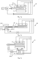
- a synchronous machine 10 With reference to Fig. 1a , an example of a synchronous machine 10 is shown.
- the exemplified synchronous machine comprises a rotor assembly 14, and a stator 16 placed outside the rotor assembly 14 periphery for electromagnetic interaction with the stator 16 via rotational motion.
- a three-phase synchronous machine 10 is exemplified in Figs 1a-c , it should be noted that a synchronous machine for the purpose of this disclosure may have any number of electrical phases.
- the rotor assembly 14 may comprise electromagnets and field windings 18, which when current flows through them, magnetise the electromagnets.
- the synchronous machine 10 further comprises an exciter 20.
- the exciter 20 is a device which is arranged to provide a direct current to the field winding(s) 18 of the rotor assembly 14 to power the electromagnet(s).
- the exciter 20 can be fed with current from stator windings 22 of the synchronous machine 10, as shown in Figs 1a-c , or by an external auxiliary power supply.
- the exciter 20 may be a rotating exciter 20-1, as shown in Fig. 1b , which comprises an exciter stator 20-1a and an exciter rotor 20-1b, the latter being formed by, for example, the shaft 12 of the rotor assembly 14 of the synchronous machine 10.
- the windings 24 of the exciter stator 20-1a are herein defined to be the stationary windings of a rotating exciter 20-1.
- the stator may have a DC/AC type stator-rotor arrangement in which case the exciter stator is fed with a direct current, as shown in Fig.
- a rectifier 32 is arranged to provide direct current to the exciter stator 20-1a.
- the exciter may have an AC/AC type stator-rotor arrangement in which case the exciter stator is fed with an alternating current. In both cases, the current output from the exciter is fed through a rectifier 25, which provides a direct current to the field windings of the rotor.
- the exciter may be a static exciter 20-2, as shown in Fig. ic, comprising a transformer 26, typically a step-down transformer.
- the primary windings 28 of the transformer 26 are connected through an auxiliary power supply or through the stator windings 22 and the secondary windings 30 are connected to a rectifier 32 which rectifies the alternating current output from the secondary windings 30 of the transformer 26 to a direct current to be fed to the field windings 18 of the rotor assembly 14 utilising brushes.
- the output of a rectifier 32 connected to the secondary windings 30 is meant.
- the synchronous machine 10 may be a low voltage machine, a medium voltage machine or a high voltage machine, and it may have any number of electrical phases.
- the present disclosure provides a synchronous machine electro-mechanical fault condition monitoring system and a method for electro-mechanical fault condition detection and determination by means of current measurements across the stationary windings of the exciter, by transforming the measured current to its frequency spectrum to obtain the harmonic content thereof, and by analysing the harmonic content.
- Fig. 2 depicts an example of a synchronous machine electro-mechanical fault condition monitoring system 1. It may be noted that the synchronous machine electro-mechanical fault condition monitoring system 1 is also shown in Figs 1a-c , where it is coupled to a respective exciter 20, 20-1, 20-2.
- the synchronous machine electro-mechanical fault condition monitoring system 1 comprises an exciter current sensor 3 arranged to measure an exciter current that flows through a stationary winding of an exciter.
- the synchronous machine electro-mechanical fault condition monitoring system 1 further comprises processor circuitry 5 and a storage unit 7.
- the processor circuitry 5 is configured to obtain exciter current signals, i.e. exciter current measurements, from the exciter current sensor 3.
- the storage unit 7 stores instructions or computer-executable components that, when executed by the processor circuitry 5 causes the synchronous machine electro-mechanical fault condition monitoring system 1 to perform the method presented herein.
- the processor circuitry 5 is thus arranged to transform the exciter current signal to obtain an exciter current frequency spectrum containing the harmonic content of the exciter current signal.
- the transformation may for example be Fourier transformation, or any variation thereof, or any other mathematical transformation that allows frequency analysis of the exciter current signal.
- the processor circuitry 5 is arranged to determine whether an electro-mechanical fault condition is present based on harmonic content of the exciter current frequency spectrum, and to identify the type of electro-mechanical fault condition.
- the present inventors have deduced a number of frequency spectra for the exciter current signal, characteristic for certain electro-mechanical fault conditions in a synchronous machine. Each of these frequency spectra is unique for a certain fault condition.
- Table I illustrates the type of failure for a rotating exciter having a DC/AC type of stator-rotor arrangement, and the corresponding signature in the harmonic content of the exciter current frequency spectrum of the transformed exciter current signal.
- f s is the power supply frequency, i.e. the frequency of the current flowing through the stator windings of the synchronous machine.
- Table I Electro-mechanical fault type Signature in harmonic content of the exciter current Rotor short-circuit 6*fs Stator short-circuit 2*fs
- Table II illustrates the type of failure for a rotating exciter having an AC/AC type of stator-rotor arrangement, and the corresponding signature in the harmonic content of the exciter current frequency spectrum of the transformed exciter current signal.
- f r is the rotation frequency of the rotor of the synchronous machine and "s" is the rotor slip of the rotating exciter, now acting as an induction generator.
- Table II ⁇ Electro-mechanical fault type Signature in harmonic content of the exciter current Rotor short-circuit f s +f r , f s -f r Stator short-circuit 3*f s (1-2 s )
- the processing circuitry 5 determines that the harmonic content of the exciter current frequency spectrum contains symmetrical sidebands around f s , with a first dominant frequency component at the sum of the power supply frequency and the rotation frequency of the rotor and a second dominant frequency component at the difference between the power supply frequency and the rotation frequency of the rotor, it can be concluded that a rotor short-circuit fault has occurred at the rotor of the synchronous machine.
- a dominant frequency component or peak
- a significant amplitude divergence from the amplitude of the surrounding frequencies is typically the amplitude of a dominant frequency component is several times greater than the amplitudes of the frequencies surrounding the dominant frequency component in the exciter current frequency spectrum.
- the processing circuitry 5 determines that the harmonic content of the exciter current frequency spectrum comprises a dominant frequency component at the rotation frequency f r of the rotor 14, compared to a frequency component at the rotation frequency of the rotor 14 present during healthy conditions, and the DC component of the exciter current signal is greater than during healthy conditions, it is determined that a static eccentricity fault is present. This is true for rotating exciters, in particular DC/AC exciters.
- the amplitude of the frequency component at the rotation frequency f r of the rotor 14 is increased during static eccentricity fault, i.e. when the rotor statically deviates from its central rotation axis inside the stator.
- the dominant frequency component which is the signature of a static eccentricity fault in this case, is a function of the rotation frequency f r of the rotor 14 and the slip s.
- the exciter current frequency spectra of a static exciter contain signatures in the exciter current frequency spectra for rotor and stator faults of the synchronous machine.
- the signature should be similar as for the rotating exciter that has AC/AC type of stator-rotor arrangement as explained above.
- the exciter current sensor 3 of the synchronous machine electro-mechanical fault condition monitoring system 1 is coupled to the stationary windings of an exciter. In the event of a rotational exciter, the exciter current sensor 3 is coupled to the exciter stator windings. In the event that the exciter is a static exciter, the exciter current sensor 3 is coupled to the primary windings of the transformer of the exciter.
- the exciter current flowing through the stationary windings is measured by the exciter current sensor 3.
- a step a) the processing circuitry 5 obtains an exciter current signal from the exciter current sensor 3.
- the exciter current signal can be the analog measurement signal of the exciter current sent by the exciter current sensor 3, or it can be a digital representation of the measured exciter current, depending on the particular implementation of the synchronous machine electro-mechanical fault condition monitoring system 1.
- the analog measurement signal is converted to a digital signal when obtained by the processing circuitry 5, whilst in the latter case it has already been converted when obtained by the processing circuitry 5.
- the exciter current signal is transformed by the processing circuitry to obtain an exciter current frequency spectrum.
- this may be a Fourier transform e.g. Fast Fourier Transformer (FFT), or any other mathematical transformation which transforms a time domain signal to the frequency domain.
- FFT Fast Fourier Transformer
- a step c) the processing circuitry 5 determines whether an electro-mechanical fault condition is present based on the harmonic content of the exciter current frequency spectrum, in particular on harmonic content related to the stator frequency of the stator 16, as the rotation frequency of the rotor is also related to the stator frequency.
- the rotation frequency of the rotor is related to the stator frequency by the number of pole pairs of the synchronous machine 10.
- the harmonic content of interest includes a component that is a rational number or an integer multiple of the stator frequency.
- a type of electro-mechanical fault condition may also be determined. The particular dominant frequency components of the harmonic content which determine whether a fault condition is present and the type of electro-mechanical fault have been presented above, in conjunction with tables I and II, and when discussing static eccentricity fault signature spectra.
- the exciter current signal is the rectifier output current output by the rectifier that feeds the brushes.
- the system and method presented herein may be utilised in a smart synchronous machine environment to diagnose electro-mechanical fault conditions of the synchronous machine, and to estimate the lifetime of the synchronous machine.
- the system and method it may be possible to determine fault conditions of a synchronous machine and to estimate when a complete breakdown of the synchronous machine would occur if a fault condition is not handled properly.
- the synchronous machine electro-mechanical fault condition monitoring system and method may be utilised in conjunction with synchronous generators and synchronous motors, involving any voltage levels utilised by such machines.
Description
- The present disclosure generally relates to synchronous machines. In particular, it relates to a method of determining whether a fault condition is present in a synchronous machine, and in case a fault condition is present, identifying the type of fault condition. Furthermore, this disclosure also relates to a computer program product and a synchronous machine electro-mechanical fault condition monitoring system which implement the method.
- Synchronous machines, i.e. synchronous motors and synchronous generators, typically comprise a rotor and a stator. The rotor and stator interact electromagnetically such that rotation of the rotor is obtained in case the synchronous machine is a motor, and such that current is induced in the stator coils in case the synchronous machine is a generator.
- A number of fault conditions may occur in a synchronous machine, both in the stator and in the rotor. Such fault conditions may instantaneously introduce noticeable deviations in behaviour of the synchronous machine, or they may go unnoticed for a longer period of time, which only after months or even years manifests itself in a catastrophic breakdown.
- Traditionally, stator current and synchronous machine vibration measurements have been preferred monitoring methods for determining the presence of a fault condition. Stator current measurements must however be performed under the high voltage conditions of the stator, which therefore requires expensive sensor equipment able to withstand such conditions, in addition to safety considerations for undertaking such measurements. Furthermore, it has been shown that vibration levels do not reflect synchronous machine conditions in a satisfactory manner.
-
CN102636751 A discloses a method where current that magnetises the electromagnets of the rotor is measured. This current is provided by an exciter, which is a device that feeds current to the rotor windings to magnetise the electromagnets of the rotor measured at the main machine rotor. The current is measured at the rotor coils to determine stator winding turn-to-turn short circuits and rotor winding turn-to-turn short circuits. The method utilises Fast Fourier Transform to extract the harmonics of the field current. - The measurements that are required in
CN102636751 A may however be difficult to implement, and the utilised sensors must be able to withstand relatively high currents. - The paper "The detection of stator and rotor winding short circuits in synchronous generators by analysing excitation current harmonics", by Penman J et al: Opportunities and advances in international electric power generation, International conference on (conf. publ. no. 419) Durham, UK 18-20 March 1996, discloses that the harmonic components present in the generator excitation current may be used to detect stator and rotor winding short circuits. It is disclosed that the machines under test have a rotating excitation system, and it is reasoned that it should be possible to detect the presence of rotor short circuits by inspection of the harmonic components in the exciter stator. Figure 8 of this disclosure shows the exciter stator current harmonic components plotted for different frequencies both under normal conditions and in the event of stator inter-turn faults, while it is concluded that from this graph that it can be seen that it may indeed be possible to detect rotor short circuits through examination of exciter current harmonics.
-
EP0306319 A1 discloses a method for statistically testing rotating rectifiers in brushless alternators. Rectifiers mounted on the rotor of a brushless alternator are tested by applying an AC voltage to an exciter field winding of the brushless alternator. This applied voltage induces current in a rotor mounted exciter armature winding which is inductively coupled to the exciter field winding and produces current flow through the rectifiers. The magnitude of an even harmonic component of the exciter field winding current is measured and compared to a predetermined magnitude to obtain an indication of the operational status of at least one of the rectifiers. This comparison may be done manually or may be performed electronically in accordance with known techniques. -
US2009/091289 A1 discloses fault detection system using field current and rotor search coil voltage harmonics. The technology is capable of detecting an inter-turn fault unambiguously and rapidly in a synchronous machine. - In view of the above, an object of the present disclosure is to provide a method and a system which simplifies fault condition type determination.
- The inventors have realised that it is possible to measure the exciter current and utilise the frequency spectrum of this current to determine a variety of different faults of a synchronous machine. With exciter current is herein meant a current that flows through stationary windings of the exciter.
- Hence, according to a first aspect of the present disclosure there is provided a method of determining an electro-mechanical fault condition in a synchronous machine having a stator a rotor, and an exciter, wherein the exciter is a rotating exciter having an exciter stator, an exciter rotor, and exciter stator windings, wherein the rotating exciter has an AC/AC type of stator-rotor arrangement, wherein the method comprises: a) obtaining an exciter current signal which is a measurement of an exciter current flowing through the exciter stator windings of the exciter, wherein the exciter current signal is an exciter stator current, b) transforming the exciter current signal to obtain an exciter current frequency spectrum, and c) determining that a stator short-circuit fault is present in case the harmonic content of the exciter current frequency spectrum comprises a dominant frequency component at 3fs*(1-2s), where fs is the power supply frequency and s is the rotor slip of the exciter.
- A technical effect which may be obtainable by means of measuring the exciter current flowing through the stationary windings of the exciter, thus obtaining the exciter current signal, is simplification of obtaining the harmonic content and thus the characteristic signature spectra of different synchronous machine electro-mechanical faults. This may in particular be obtained because the measurement point is stationary and outside the machine rotating parts. This is a surprising result found by the inventors. In particular, it is surprising that electro-mechanical faults related to the main machine, e.g. rotor, stator and eccentricity faults, propagate through a rectifier and inductively to the exciter stator in the case of a rotating exciter, and inductively through a transformer core of a step-down transformer in the event of a static exciter.
- Furthermore, the currents are lower at the stationary windings of the exciter than in the main machine parts, resulting in that the sensor(s) utilised can be rated for lower currents than when currents are measured at the rotor, or stator, of a synchronous machine, further facilitating the compliance with the safety considerations on the machine side measurements. Cheaper sensors may therefore be utilised for the exciter current measurements.
- With electro-mechanical fault is meant an electrical fault that arises due to mechanical damage.
- According to one embodiment in case the harmonic content of the exciter current frequency spectrum comprises a first dominant frequency component at the difference of the power supply frequency and a rotation frequency of the rotor and a second dominant frequency component at the sum of the power supply frequency and the rotation frequency of the rotor, it is determined in step c) that a rotor short-circuit fault is present.
- According to a second aspect of the present disclosure there is provided a computer program product comprising computer-executable components for causing a synchronous machine electro-mechanical fault condition monitoring system according to the third aspect to perform the method according to the first aspect when the computer-executable components are run on processor circuitry of the synchronous machine electro-mechanical fault condition monitoring system. According to a third aspect of the present disclosure there is provided a synchronous machine electro-mechanical fault condition monitoring system comprising an exciter current sensor arranged to measure an exciter current flowing through stationary windings of an exciter, processor circuitry arranged to receive an exciter current signal of a measured exciter current, from the exciter current sensor, and a storage unit storing instructions that, when executed by the processor circuitry causes the synchronous machine electro-mechanical fault condition monitoring system to perform the method according to the first aspect.
- Generally, all terms used in the claims are to be interpreted according to their ordinary meaning in the technical field, unless explicitly defined otherwise herein. All references to "a/an/the element, apparatus, component, means, etc. are to be interpreted openly as referring to at least one instance of the element, apparatus, component, means, etc., unless explicitly stated otherwise. Moreover, any steps of the method presented herein need not necessarily be performed in the described order, unless explicitly stated so.
- The specific embodiments of the inventive concept will now be described, by way of example, with reference to the accompanying drawings, in which:
-
Fig. 1a schematically depicts an example of a general three-phase synchronous machine configuration; -
Fig. 1b schematically depicts an example of a three-phase synchronous machine configuration with a rotating exciter; -
Fig. 1c schematically depicts an example of a general three-phase synchronous machine configuration with a static exciter; -
Fig. 2 schematically depicts an example of a synchronous machine electro-mechanical fault condition monitoring system; -
Fig. 3 is a flow chart of a method of determining a fault condition in a synchronous machine, which may be carried out by the synchronous machine electro-mechanical fault condition monitoring system inFig. 2 . - The inventive concept will now be described more fully hereinafter with reference to the accompanying drawings, in which exemplifying embodiments are shown. The inventive concept may, however, be embodied in many different forms and should not be construed as limited to the embodiments set forth herein; rather, these embodiments are provided by way of example so that this disclosure will be thorough and complete, and will fully convey the scope of the inventive concept to those skilled in the art. Like numbers refer to like elements throughout the description.
- With reference to
Fig. 1a , an example of asynchronous machine 10 is shown. The exemplified synchronous machine comprises arotor assembly 14, and astator 16 placed outside therotor assembly 14 periphery for electromagnetic interaction with thestator 16 via rotational motion. Although a three-phasesynchronous machine 10 is exemplified inFigs 1a-c , it should be noted that a synchronous machine for the purpose of this disclosure may have any number of electrical phases. - The
rotor assembly 14 may comprise electromagnets andfield windings 18, which when current flows through them, magnetise the electromagnets. Thesynchronous machine 10 further comprises anexciter 20. Theexciter 20 is a device which is arranged to provide a direct current to the field winding(s) 18 of therotor assembly 14 to power the electromagnet(s). Theexciter 20 can be fed with current fromstator windings 22 of thesynchronous machine 10, as shown inFigs 1a-c , or by an external auxiliary power supply. - The
exciter 20 may be a rotating exciter 20-1, as shown inFig. 1b , which comprises an exciter stator 20-1a and an exciter rotor 20-1b, the latter being formed by, for example, theshaft 12 of therotor assembly 14 of thesynchronous machine 10. Thewindings 24 of the exciter stator 20-1a are herein defined to be the stationary windings of a rotating exciter 20-1. In the event the exciter is a rotating exciter, the stator may have a DC/AC type stator-rotor arrangement in which case the exciter stator is fed with a direct current, as shown inFig. 1b , in which case arectifier 32 is arranged to provide direct current to the exciter stator 20-1a. Alternatively, the exciter may have an AC/AC type stator-rotor arrangement in which case the exciter stator is fed with an alternating current. In both cases, the current output from the exciter is fed through arectifier 25, which provides a direct current to the field windings of the rotor. - As an alternative to a rotating exciter, the exciter may be a static exciter 20-2, as shown in Fig. ic, comprising a
transformer 26, typically a step-down transformer. Theprimary windings 28 of thetransformer 26 are connected through an auxiliary power supply or through thestator windings 22 and thesecondary windings 30 are connected to arectifier 32 which rectifies the alternating current output from thesecondary windings 30 of thetransformer 26 to a direct current to be fed to thefield windings 18 of therotor assembly 14 utilising brushes. When referring to stationary windings in the context of a static exciter in the following, the output of arectifier 32 connected to thesecondary windings 30 is meant. - The
synchronous machine 10 may be a low voltage machine, a medium voltage machine or a high voltage machine, and it may have any number of electrical phases. - The present disclosure provides a synchronous machine electro-mechanical fault condition monitoring system and a method for electro-mechanical fault condition detection and determination by means of current measurements across the stationary windings of the exciter, by transforming the measured current to its frequency spectrum to obtain the harmonic content thereof, and by analysing the harmonic content.
-
Fig. 2 depicts an example of a synchronous machine electro-mechanical faultcondition monitoring system 1. It may be noted that the synchronous machine electro-mechanical faultcondition monitoring system 1 is also shown inFigs 1a-c , where it is coupled to arespective exciter 20, 20-1, 20-2. - The synchronous machine electro-mechanical fault
condition monitoring system 1 comprises an excitercurrent sensor 3 arranged to measure an exciter current that flows through a stationary winding of an exciter. - The synchronous machine electro-mechanical fault
condition monitoring system 1 further comprisesprocessor circuitry 5 and astorage unit 7. Theprocessor circuitry 5 is configured to obtain exciter current signals, i.e. exciter current measurements, from the excitercurrent sensor 3. Thestorage unit 7 stores instructions or computer-executable components that, when executed by theprocessor circuitry 5 causes the synchronous machine electro-mechanical faultcondition monitoring system 1 to perform the method presented herein. Theprocessor circuitry 5 is thus arranged to transform the exciter current signal to obtain an exciter current frequency spectrum containing the harmonic content of the exciter current signal. The transformation may for example be Fourier transformation, or any variation thereof, or any other mathematical transformation that allows frequency analysis of the exciter current signal. - Furthermore, the
processor circuitry 5 is arranged to determine whether an electro-mechanical fault condition is present based on harmonic content of the exciter current frequency spectrum, and to identify the type of electro-mechanical fault condition. - The present inventors have deduced a number of frequency spectra for the exciter current signal, characteristic for certain electro-mechanical fault conditions in a synchronous machine. Each of these frequency spectra is unique for a certain fault condition.
- Table I below illustrates the type of failure for a rotating exciter having a DC/AC type of stator-rotor arrangement, and the corresponding signature in the harmonic content of the exciter current frequency spectrum of the transformed exciter current signal. fs is the power supply frequency, i.e. the frequency of the current flowing through the stator windings of the synchronous machine.
Table I Electro-mechanical fault type Signature in harmonic content of the exciter current Rotor short-circuit 6*fs Stator short-circuit 2*fs - Thus, in the event that it is determined by the
processing circuitry 5 that the harmonic content of the exciter current frequency spectrum contains a dominant frequency component at six times the power supply frequency, it can be concluded that a rotor short-circuit fault has occurred at the rotor of the synchronous machine. - In the event that it is determined by the
processing circuitry 5 that the harmonic content of the exciter current frequency contains a dominant frequency component at two times the power supply frequency, it can be concluded that a stator short-circuit fault has occurred at the stator of the synchronous machine. - Table II below illustrates the type of failure for a rotating exciter having an AC/AC type of stator-rotor arrangement, and the corresponding signature in the harmonic content of the exciter current frequency spectrum of the transformed exciter current signal. fr is the rotation frequency of the rotor of the synchronous machine and "s" is the rotor slip of the rotating exciter, now acting as an induction generator.
Table II \Electro-mechanical fault type Signature in harmonic content of the exciter current Rotor short-circuit fs+fr, fs-fr Stator short- circuit 3*fs(1-2s) - Thus, in the event that it is determined by the
processing circuitry 5 that the harmonic content of the exciter current frequency spectrum contains symmetrical sidebands around fs, with a first dominant frequency component at the sum of the power supply frequency and the rotation frequency of the rotor and a second dominant frequency component at the difference between the power supply frequency and the rotation frequency of the rotor, it can be concluded that a rotor short-circuit fault has occurred at the rotor of the synchronous machine. - In the event that it is determined by the
processing circuitry 5 that the harmonic content of the exciter current frequency spectrum contains a dominant frequency component at three times the difference between the power supply frequency and two times the rotor slip, i.e. at 3*fs(1-2s), it can be concluded that a stator short-circuit fault has occurred at the stator of the synchronous machine. - With a dominant frequency component, or peak, is meant a significant amplitude divergence from the amplitude of the surrounding frequencies. Typically the amplitude of a dominant frequency component is several times greater than the amplitudes of the frequencies surrounding the dominant frequency component in the exciter current frequency spectrum.
- In the event that it is determined by the
processing circuitry 5 that the harmonic content of the exciter current frequency spectrum comprises a dominant frequency component at the rotation frequency fr of therotor 14, compared to a frequency component at the rotation frequency of therotor 14 present during healthy conditions, and the DC component of the exciter current signal is greater than during healthy conditions, it is determined that a static eccentricity fault is present. This is true for rotating exciters, in particular DC/AC exciters. Thus, the amplitude of the frequency component at the rotation frequency fr of therotor 14, is increased during static eccentricity fault, i.e. when the rotor statically deviates from its central rotation axis inside the stator. - In case of an AC/AC exciter, the dominant frequency component, which is the signature of a static eccentricity fault in this case, is a function of the rotation frequency fr of the
rotor 14 and the slip s. - In a similar manner, the exciter current frequency spectra of a static exciter contain signatures in the exciter current frequency spectra for rotor and stator faults of the synchronous machine. Theoretically, the signature should be similar as for the rotating exciter that has AC/AC type of stator-rotor arrangement as explained above.
- With reference to
Fig. 3 , a method of determining an electro-mechanical fault condition in a synchronous machine by means of the synchronous machine electro-mechanical faultcondition monitoring system 1 will now be described. - The exciter
current sensor 3 of the synchronous machine electro-mechanical faultcondition monitoring system 1 is coupled to the stationary windings of an exciter. In the event of a rotational exciter, the excitercurrent sensor 3 is coupled to the exciter stator windings. In the event that the exciter is a static exciter, the excitercurrent sensor 3 is coupled to the primary windings of the transformer of the exciter. - The exciter current flowing through the stationary windings is measured by the exciter
current sensor 3. - In a step a) the
processing circuitry 5 obtains an exciter current signal from the excitercurrent sensor 3. The exciter current signal can be the analog measurement signal of the exciter current sent by the excitercurrent sensor 3, or it can be a digital representation of the measured exciter current, depending on the particular implementation of the synchronous machine electro-mechanical faultcondition monitoring system 1. In the former case, the analog measurement signal is converted to a digital signal when obtained by theprocessing circuitry 5, whilst in the latter case it has already been converted when obtained by theprocessing circuitry 5. - In a step b) the exciter current signal is transformed by the processing circuitry to obtain an exciter current frequency spectrum. As previously mentioned, this may be a Fourier transform e.g. Fast Fourier Transformer (FFT), or any other mathematical transformation which transforms a time domain signal to the frequency domain.
- In a step c) the
processing circuitry 5 determines whether an electro-mechanical fault condition is present based on the harmonic content of the exciter current frequency spectrum, in particular on harmonic content related to the stator frequency of thestator 16, as the rotation frequency of the rotor is also related to the stator frequency. The rotation frequency of the rotor is related to the stator frequency by the number of pole pairs of thesynchronous machine 10. In general, the harmonic content of interest includes a component that is a rational number or an integer multiple of the stator frequency. Furthermore, based on the content of the frequency spectrum, a type of electro-mechanical fault condition may also be determined. The particular dominant frequency components of the harmonic content which determine whether a fault condition is present and the type of electro-mechanical fault have been presented above, in conjunction with tables I and II, and when discussing static eccentricity fault signature spectra. - In the case of a static exciter, the exciter current signal is the rectifier output current output by the rectifier that feeds the brushes.
- It is envisaged that the system and method presented herein may be utilised in a smart synchronous machine environment to diagnose electro-mechanical fault conditions of the synchronous machine, and to estimate the lifetime of the synchronous machine. By means of the system and method, it may be possible to determine fault conditions of a synchronous machine and to estimate when a complete breakdown of the synchronous machine would occur if a fault condition is not handled properly. The synchronous machine electro-mechanical fault condition monitoring system and method may be utilised in conjunction with synchronous generators and synchronous motors, involving any voltage levels utilised by such machines.
- The inventive concept has mainly been described above with reference to a few examples. However, as is readily appreciated by a person skilled in the art, other embodiments than the ones disclosed above are equally possible within the scope of the inventive concept, as defined by the appended claims.
Claims (4)
- A method of determining an electro-mechanical fault condition in a synchronous machine (10) having a stator (16) a rotor (14), and an exciter (20-1), wherein the exciter (20-1) is a rotating exciter having an exciter stator (20-1a) an exciter rotor (20-1b), and exciter stator windings (24), wherein the method comprises:a) obtaining an exciter current signal which is a measurement of an exciter current flowing through the exciter stator windings (24) of the exciter (20-1), wherein the exciter current signal is an exciter stator current,b) transforming the exciter current signal to obtain an exciter current frequency spectrum,
characterised in that the rotating exciter (20-1) has an AC/AC type of stator-rotor arrangement, and in that the method comprises:c) determining that a stator short-circuit fault is present in case the harmonic content of the exciter current frequency spectrum comprises a dominant frequency component at 3fs*(1-2s), where fs is the power supply frequency and s is the rotor slip of the exciter (20-1). - The method as claimed in claim 1, wherein in case the harmonic content of the exciter current frequency spectrum comprises a first dominant frequency component at the difference of the power supply frequency and a rotation frequency of the rotor and a second dominant frequency component at the sum of the power supply frequency and the rotation frequency of the rotor, it is determined in step c) that a rotor short-circuit fault is present.
- A computer program product comprising computer-executable components for causing a synchronous machine electro-mechanical fault condition monitoring system as claimed in claim 4 to perform the method as claimed in claim 1 or 2 when the computer-executable components are run on processor circuitry of the synchronous machine electro-mechanical fault condition monitoring system.
- A synchronous machine electro-mechanical fault condition monitoring system (1) comprising:an exciter current sensor (3) arranged to measure an exciter current flowing through stationary windings (24) of an exciter (20-1),processor circuitry (5) arranged to receive an exciter current signal of a measured exciter current, from the exciter current sensor, anda storage unit (7) storing instructions that, when executed by the processor circuitry (5) causes the synchronous machine electro-mechanical fault condition monitoring system (1) to perform the method as claimed in claim 1 or 2.
Applications Claiming Priority (3)
| Application Number | Priority Date | Filing Date | Title |
|---|---|---|---|
| EP14184248.4A EP2995967A1 (en) | 2014-09-10 | 2014-09-10 | Method and system for determining a synchronous machine fault condition |
| EP15757513.5A EP3191859B1 (en) | 2014-09-10 | 2015-09-08 | Method and system for determining a synchronous machine fault condition |
| PCT/EP2015/070419 WO2016037995A2 (en) | 2014-09-10 | 2015-09-08 | Method and system for determining a synchronous machine fault condition |
Related Parent Applications (2)
| Application Number | Title | Priority Date | Filing Date |
|---|---|---|---|
| EP15757513.5A Division EP3191859B1 (en) | 2014-09-10 | 2015-09-08 | Method and system for determining a synchronous machine fault condition |
| EP15757513.5A Division-Into EP3191859B1 (en) | 2014-09-10 | 2015-09-08 | Method and system for determining a synchronous machine fault condition |
Publications (2)
| Publication Number | Publication Date |
|---|---|
| EP3321706A1 EP3321706A1 (en) | 2018-05-16 |
| EP3321706B1 true EP3321706B1 (en) | 2021-12-08 |
Family
ID=51494196
Family Applications (3)
| Application Number | Title | Priority Date | Filing Date |
|---|---|---|---|
| EP14184248.4A Withdrawn EP2995967A1 (en) | 2014-09-10 | 2014-09-10 | Method and system for determining a synchronous machine fault condition |
| EP17195616.2A Active EP3321706B1 (en) | 2014-09-10 | 2015-09-08 | Method and system for determining a synchronous machine fault condition |
| EP15757513.5A Active EP3191859B1 (en) | 2014-09-10 | 2015-09-08 | Method and system for determining a synchronous machine fault condition |
Family Applications Before (1)
| Application Number | Title | Priority Date | Filing Date |
|---|---|---|---|
| EP14184248.4A Withdrawn EP2995967A1 (en) | 2014-09-10 | 2014-09-10 | Method and system for determining a synchronous machine fault condition |
Family Applications After (1)
| Application Number | Title | Priority Date | Filing Date |
|---|---|---|---|
| EP15757513.5A Active EP3191859B1 (en) | 2014-09-10 | 2015-09-08 | Method and system for determining a synchronous machine fault condition |
Country Status (5)
| Country | Link |
|---|---|
| US (1) | US9977085B2 (en) |
| EP (3) | EP2995967A1 (en) |
| CN (1) | CN106716157B (en) |
| BR (1) | BR112017004144B1 (en) |
| WO (1) | WO2016037995A2 (en) |
Families Citing this family (13)
| Publication number | Priority date | Publication date | Assignee | Title |
|---|---|---|---|---|
| EP3236275B1 (en) * | 2016-04-18 | 2021-11-17 | ABB Schweiz AG | Electrical machine comprising a rotor measurement unit for measuring a rotor parameter of the electrical machine |
| GB201616900D0 (en) * | 2016-10-05 | 2016-11-16 | Rolls Royce Plc | Brushless synchronous generator stator winding fault |
| EP3312988B1 (en) | 2016-10-18 | 2020-12-02 | ABB Schweiz AG | A method for detecting a fault in an electrical machine |
| WO2018184673A1 (en) * | 2017-04-05 | 2018-10-11 | Abb Schweiz Ag | An electrical machine comprising a rotor measurement unit for measuring a rotor parameter of the electrical machine |
| CN108427072A (en) * | 2017-12-12 | 2018-08-21 | 神华集团有限责任公司 | Detection method and device for synchronous machine rotating excitation system |
| CN108680858B (en) * | 2018-06-01 | 2020-02-04 | 清华大学 | Method and system for monitoring loss of field fault of permanent magnet synchronous motor rotor |
| CN113170576A (en) * | 2019-01-21 | 2021-07-23 | 株式会社村田制作所 | Stretchable wiring board |
| CN112162213A (en) * | 2020-08-25 | 2021-01-01 | 辽宁红沿河核电有限公司 | Excitation winding short-circuit fault detection method and device of multi-phase angular brushless excitation system |
| CN112198449A (en) * | 2020-08-25 | 2021-01-08 | 中广核核电运营有限公司 | Excitation winding short-circuit fault detection method and device of brushless excitation system |
| CN112782578A (en) * | 2021-02-03 | 2021-05-11 | 安徽大学绿色产业创新研究院 | Asymmetric fault diagnosis method for stator winding of permanent magnet synchronous motor |
| CN113625117A (en) * | 2021-08-17 | 2021-11-09 | 河北工业大学 | Motor stator turn-to-turn short circuit fault diagnosis method, device and system |
| CN114527384B (en) * | 2022-03-07 | 2023-10-27 | 江苏斯菲尔电气股份有限公司 | Motor protection and fault diagnosis controller with industrial Ethernet |
| CN117096823B (en) * | 2023-10-20 | 2024-03-08 | 南方电网调峰调频发电有限公司 | Method and device for protecting rotor short circuit fault of variable speed pumping and accumulating unit |
Family Cites Families (6)
| Publication number | Priority date | Publication date | Assignee | Title |
|---|---|---|---|---|
| US4816756A (en) * | 1987-09-03 | 1989-03-28 | Westinghouse Electric Corp. | Circuit and method for statically testing rotating rectifiers in brushless alternators |
| US7592772B2 (en) * | 2007-10-08 | 2009-09-22 | University Of Victoria Innovation And Development Corporation | Stator inter-turn fault detection of synchronous machines |
| US20090296777A1 (en) * | 2008-05-30 | 2009-12-03 | General Electric Company | Method and apparatus for detecting a fault in a brushless exciter for a generator |
| CN102636751A (en) | 2012-04-26 | 2012-08-15 | 中国人民解放军海军工程大学 | Alternating-current brushless generator fault detection method based on exciter exciting current |
| CN202856679U (en) | 2012-09-17 | 2013-04-03 | 西北工业大学 | Excitation control device in start process of aviation triple brushless alternating current synchronous motor |
| CN103926506B (en) * | 2014-02-25 | 2016-04-20 | 华北电力大学(保定) | Based on the rotor of steam turbo generator Winding Short Fault Diagnosis method of constructor |
-
2014
- 2014-09-10 EP EP14184248.4A patent/EP2995967A1/en not_active Withdrawn
-
2015
- 2015-09-08 US US15/507,110 patent/US9977085B2/en active Active
- 2015-09-08 CN CN201580049258.3A patent/CN106716157B/en active Active
- 2015-09-08 WO PCT/EP2015/070419 patent/WO2016037995A2/en active Application Filing
- 2015-09-08 EP EP17195616.2A patent/EP3321706B1/en active Active
- 2015-09-08 BR BR112017004144-8A patent/BR112017004144B1/en active IP Right Grant
- 2015-09-08 EP EP15757513.5A patent/EP3191859B1/en active Active
Also Published As
| Publication number | Publication date |
|---|---|
| EP2995967A1 (en) | 2016-03-16 |
| CN106716157A (en) | 2017-05-24 |
| US9977085B2 (en) | 2018-05-22 |
| EP3191859A2 (en) | 2017-07-19 |
| WO2016037995A3 (en) | 2016-06-02 |
| EP3191859B1 (en) | 2020-11-04 |
| CN106716157B (en) | 2019-07-26 |
| BR112017004144B1 (en) | 2022-06-21 |
| US20180052206A1 (en) | 2018-02-22 |
| BR112017004144A2 (en) | 2017-12-12 |
| WO2016037995A2 (en) | 2016-03-17 |
| EP3321706A1 (en) | 2018-05-16 |
Similar Documents
| Publication | Publication Date | Title |
|---|---|---|
| EP3321706B1 (en) | Method and system for determining a synchronous machine fault condition | |
| Drif et al. | Stator fault diagnostics in squirrel cage three-phase induction motor drives using the instantaneous active and reactive power signature analyses | |
| Surya et al. | A simplified frequency-domain detection of stator turn fault in squirrel-cage induction motors using an observer coil technique | |
| US9261562B2 (en) | Portable system for immotive multiphasic motive force electrical machine testing | |
| Da et al. | A new approach to fault diagnostics for permanent magnet synchronous machines using electromagnetic signature analysis | |
| Tallam et al. | A survey of methods for detection of stator-related faults in induction machines | |
| EP2919026B1 (en) | Method and system for determining a synchronous machine fault condition | |
| Kim et al. | Reliable detection of rotor faults under the influence of low-frequency load torque oscillations for applications with speed reduction couplings | |
| Hyun et al. | Detection of airgap eccentricity for induction motors using the single-phase rotation test | |
| Yun et al. | Airgap search coil-based detection of damper bar failures in salient pole synchronous motors | |
| Park et al. | Air gap flux-based detection and classification of damper bar and field winding faults in salient pole synchronous motors | |
| Shaikh et al. | A non-intrusive leakage flux based method for detecting rotor faults in the starting transient of salient pole synchronous motors | |
| Yun et al. | Comprehensive monitoring of field winding short circuits for salient pole synchronous motors | |
| Antonino-Daviu et al. | Electrical monitoring of damper bar condition in salient-pole synchronous motors without motor disassembly | |
| Frosini | Monitoring and diagnostics of electrical machines and drives: A state of the art | |
| Rafaq et al. | Reliable airgap search coil based detection of induction motor rotor faults under false negative motor current signature analysis indications | |
| Goktas et al. | Separation of induction motor rotor faults and low frequency load oscillations through the radial leakage flux | |
| Park et al. | Flux-based detection of non-adjacent rotor bar damage in squirrel cage induction motors | |
| Batzel et al. | Predictive diagnostics for the main field winding and rotating rectifier assembly in the brushless synchronous generator | |
| Antonino-Daviu et al. | Reliable detection of induction motor rotor faults under the influence of rotor core magnetic anisotropy | |
| Lee et al. | A stator-core quality-assessment technique for inverter-fed induction machines | |
| Gyftakis et al. | Introduction of the zero-sequence stray flux as a reliable diagnostic method of rotor electrical faults in induction motors | |
| Ehya et al. | Inter-turn short circuit fault identification of salient pole synchronous generators by descriptive paradigm | |
| Safa et al. | Eccentricity fault detection in permanent magnet synchronous generators using stator voltage signature analysis | |
| Gyftakis et al. | Multi-parametric monitoring of medium-power generators with brushless exciters under mechanical faults |
Legal Events
| Date | Code | Title | Description |
|---|---|---|---|
| PUAI | Public reference made under article 153(3) epc to a published international application that has entered the european phase |
Free format text: ORIGINAL CODE: 0009012 |
|
| STAA | Information on the status of an ep patent application or granted ep patent |
Free format text: STATUS: THE APPLICATION HAS BEEN PUBLISHED |
|
| AC | Divisional application: reference to earlier application |
Ref document number: 3191859 Country of ref document: EP Kind code of ref document: P |
|
| AK | Designated contracting states |
Kind code of ref document: A1 Designated state(s): AL AT BE BG CH CY CZ DE DK EE ES FI FR GB GR HR HU IE IS IT LI LT LU LV MC MK MT NL NO PL PT RO RS SE SI SK SM TR |
|
| AX | Request for extension of the european patent |
Extension state: BA ME |
|
| STAA | Information on the status of an ep patent application or granted ep patent |
Free format text: STATUS: REQUEST FOR EXAMINATION WAS MADE |
|
| 17P | Request for examination filed |
Effective date: 20181116 |
|
| RBV | Designated contracting states (corrected) |
Designated state(s): AL AT BE BG CH CY CZ DE DK EE ES FI FR GB GR HR HU IE IS IT LI LT LU LV MC MK MT NL NO PL PT RO RS SE SI SK SM TR |
|
| STAA | Information on the status of an ep patent application or granted ep patent |
Free format text: STATUS: REQUEST FOR EXAMINATION WAS MADE |
|
| GRAP | Despatch of communication of intention to grant a patent |
Free format text: ORIGINAL CODE: EPIDOSNIGR1 |
|
| STAA | Information on the status of an ep patent application or granted ep patent |
Free format text: STATUS: GRANT OF PATENT IS INTENDED |
|
| INTG | Intention to grant announced |
Effective date: 20210702 |
|
| GRAS | Grant fee paid |
Free format text: ORIGINAL CODE: EPIDOSNIGR3 |
|
| GRAA | (expected) grant |
Free format text: ORIGINAL CODE: 0009210 |
|
| STAA | Information on the status of an ep patent application or granted ep patent |
Free format text: STATUS: THE PATENT HAS BEEN GRANTED |
|
| RAP3 | Party data changed (applicant data changed or rights of an application transferred) |
Owner name: ABB SCHWEIZ AG |
|
| AC | Divisional application: reference to earlier application |
Ref document number: 3191859 Country of ref document: EP Kind code of ref document: P |
|
| AK | Designated contracting states |
Kind code of ref document: B1 Designated state(s): AL AT BE BG CH CY CZ DE DK EE ES FI FR GB GR HR HU IE IS IT LI LT LU LV MC MK MT NL NO PL PT RO RS SE SI SK SM TR |
|
| REG | Reference to a national code |
Ref country code: GB Ref legal event code: FG4D |
|
| REG | Reference to a national code |
Ref country code: AT Ref legal event code: REF Ref document number: 1454167 Country of ref document: AT Kind code of ref document: T Effective date: 20211215 Ref country code: CH Ref legal event code: EP |
|
| REG | Reference to a national code |
Ref country code: DE Ref legal event code: R096 Ref document number: 602015075712 Country of ref document: DE |
|
| REG | Reference to a national code |
Ref country code: IE Ref legal event code: FG4D |
|
| REG | Reference to a national code |
Ref country code: LT Ref legal event code: MG9D |
|
| REG | Reference to a national code |
Ref country code: NL Ref legal event code: MP Effective date: 20211208 |
|
| PG25 | Lapsed in a contracting state [announced via postgrant information from national office to epo] |
Ref country code: RS Free format text: LAPSE BECAUSE OF FAILURE TO SUBMIT A TRANSLATION OF THE DESCRIPTION OR TO PAY THE FEE WITHIN THE PRESCRIBED TIME-LIMIT Effective date: 20211208 Ref country code: LT Free format text: LAPSE BECAUSE OF FAILURE TO SUBMIT A TRANSLATION OF THE DESCRIPTION OR TO PAY THE FEE WITHIN THE PRESCRIBED TIME-LIMIT Effective date: 20211208 Ref country code: FI Free format text: LAPSE BECAUSE OF FAILURE TO SUBMIT A TRANSLATION OF THE DESCRIPTION OR TO PAY THE FEE WITHIN THE PRESCRIBED TIME-LIMIT Effective date: 20211208 Ref country code: BG Free format text: LAPSE BECAUSE OF FAILURE TO SUBMIT A TRANSLATION OF THE DESCRIPTION OR TO PAY THE FEE WITHIN THE PRESCRIBED TIME-LIMIT Effective date: 20220308 |
|
| REG | Reference to a national code |
Ref country code: AT Ref legal event code: MK05 Ref document number: 1454167 Country of ref document: AT Kind code of ref document: T Effective date: 20211208 |
|
| PG25 | Lapsed in a contracting state [announced via postgrant information from national office to epo] |
Ref country code: SE Free format text: LAPSE BECAUSE OF FAILURE TO SUBMIT A TRANSLATION OF THE DESCRIPTION OR TO PAY THE FEE WITHIN THE PRESCRIBED TIME-LIMIT Effective date: 20211208 Ref country code: NO Free format text: LAPSE BECAUSE OF FAILURE TO SUBMIT A TRANSLATION OF THE DESCRIPTION OR TO PAY THE FEE WITHIN THE PRESCRIBED TIME-LIMIT Effective date: 20220308 Ref country code: LV Free format text: LAPSE BECAUSE OF FAILURE TO SUBMIT A TRANSLATION OF THE DESCRIPTION OR TO PAY THE FEE WITHIN THE PRESCRIBED TIME-LIMIT Effective date: 20211208 Ref country code: HR Free format text: LAPSE BECAUSE OF FAILURE TO SUBMIT A TRANSLATION OF THE DESCRIPTION OR TO PAY THE FEE WITHIN THE PRESCRIBED TIME-LIMIT Effective date: 20211208 Ref country code: GR Free format text: LAPSE BECAUSE OF FAILURE TO SUBMIT A TRANSLATION OF THE DESCRIPTION OR TO PAY THE FEE WITHIN THE PRESCRIBED TIME-LIMIT Effective date: 20220309 Ref country code: ES Free format text: LAPSE BECAUSE OF FAILURE TO SUBMIT A TRANSLATION OF THE DESCRIPTION OR TO PAY THE FEE WITHIN THE PRESCRIBED TIME-LIMIT Effective date: 20211208 |
|
| PG25 | Lapsed in a contracting state [announced via postgrant information from national office to epo] |
Ref country code: NL Free format text: LAPSE BECAUSE OF FAILURE TO SUBMIT A TRANSLATION OF THE DESCRIPTION OR TO PAY THE FEE WITHIN THE PRESCRIBED TIME-LIMIT Effective date: 20211208 |
|
| PG25 | Lapsed in a contracting state [announced via postgrant information from national office to epo] |
Ref country code: SM Free format text: LAPSE BECAUSE OF FAILURE TO SUBMIT A TRANSLATION OF THE DESCRIPTION OR TO PAY THE FEE WITHIN THE PRESCRIBED TIME-LIMIT Effective date: 20211208 Ref country code: SK Free format text: LAPSE BECAUSE OF FAILURE TO SUBMIT A TRANSLATION OF THE DESCRIPTION OR TO PAY THE FEE WITHIN THE PRESCRIBED TIME-LIMIT Effective date: 20211208 Ref country code: RO Free format text: LAPSE BECAUSE OF FAILURE TO SUBMIT A TRANSLATION OF THE DESCRIPTION OR TO PAY THE FEE WITHIN THE PRESCRIBED TIME-LIMIT Effective date: 20211208 Ref country code: PT Free format text: LAPSE BECAUSE OF FAILURE TO SUBMIT A TRANSLATION OF THE DESCRIPTION OR TO PAY THE FEE WITHIN THE PRESCRIBED TIME-LIMIT Effective date: 20220408 Ref country code: EE Free format text: LAPSE BECAUSE OF FAILURE TO SUBMIT A TRANSLATION OF THE DESCRIPTION OR TO PAY THE FEE WITHIN THE PRESCRIBED TIME-LIMIT Effective date: 20211208 Ref country code: CZ Free format text: LAPSE BECAUSE OF FAILURE TO SUBMIT A TRANSLATION OF THE DESCRIPTION OR TO PAY THE FEE WITHIN THE PRESCRIBED TIME-LIMIT Effective date: 20211208 |
|
| PG25 | Lapsed in a contracting state [announced via postgrant information from national office to epo] |
Ref country code: PL Free format text: LAPSE BECAUSE OF FAILURE TO SUBMIT A TRANSLATION OF THE DESCRIPTION OR TO PAY THE FEE WITHIN THE PRESCRIBED TIME-LIMIT Effective date: 20211208 Ref country code: AT Free format text: LAPSE BECAUSE OF FAILURE TO SUBMIT A TRANSLATION OF THE DESCRIPTION OR TO PAY THE FEE WITHIN THE PRESCRIBED TIME-LIMIT Effective date: 20211208 |
|
| REG | Reference to a national code |
Ref country code: DE Ref legal event code: R097 Ref document number: 602015075712 Country of ref document: DE |
|
| PG25 | Lapsed in a contracting state [announced via postgrant information from national office to epo] |
Ref country code: IS Free format text: LAPSE BECAUSE OF FAILURE TO SUBMIT A TRANSLATION OF THE DESCRIPTION OR TO PAY THE FEE WITHIN THE PRESCRIBED TIME-LIMIT Effective date: 20220408 |
|
| PLBE | No opposition filed within time limit |
Free format text: ORIGINAL CODE: 0009261 |
|
| STAA | Information on the status of an ep patent application or granted ep patent |
Free format text: STATUS: NO OPPOSITION FILED WITHIN TIME LIMIT |
|
| PG25 | Lapsed in a contracting state [announced via postgrant information from national office to epo] |
Ref country code: DK Free format text: LAPSE BECAUSE OF FAILURE TO SUBMIT A TRANSLATION OF THE DESCRIPTION OR TO PAY THE FEE WITHIN THE PRESCRIBED TIME-LIMIT Effective date: 20211208 Ref country code: AL Free format text: LAPSE BECAUSE OF FAILURE TO SUBMIT A TRANSLATION OF THE DESCRIPTION OR TO PAY THE FEE WITHIN THE PRESCRIBED TIME-LIMIT Effective date: 20211208 |
|
| 26N | No opposition filed |
Effective date: 20220909 |
|
| PG25 | Lapsed in a contracting state [announced via postgrant information from national office to epo] |
Ref country code: SI Free format text: LAPSE BECAUSE OF FAILURE TO SUBMIT A TRANSLATION OF THE DESCRIPTION OR TO PAY THE FEE WITHIN THE PRESCRIBED TIME-LIMIT Effective date: 20211208 |
|
| PG25 | Lapsed in a contracting state [announced via postgrant information from national office to epo] |
Ref country code: MC Free format text: LAPSE BECAUSE OF FAILURE TO SUBMIT A TRANSLATION OF THE DESCRIPTION OR TO PAY THE FEE WITHIN THE PRESCRIBED TIME-LIMIT Effective date: 20211208 |
|
| REG | Reference to a national code |
Ref country code: CH Ref legal event code: PL |
|
| REG | Reference to a national code |
Ref country code: BE Ref legal event code: MM Effective date: 20220930 |
|
| PG25 | Lapsed in a contracting state [announced via postgrant information from national office to epo] |
Ref country code: IT Free format text: LAPSE BECAUSE OF FAILURE TO SUBMIT A TRANSLATION OF THE DESCRIPTION OR TO PAY THE FEE WITHIN THE PRESCRIBED TIME-LIMIT Effective date: 20211208 |
|
| PG25 | Lapsed in a contracting state [announced via postgrant information from national office to epo] |
Ref country code: LU Free format text: LAPSE BECAUSE OF NON-PAYMENT OF DUE FEES Effective date: 20220908 |
|
| PG25 | Lapsed in a contracting state [announced via postgrant information from national office to epo] |
Ref country code: LI Free format text: LAPSE BECAUSE OF NON-PAYMENT OF DUE FEES Effective date: 20220930 Ref country code: IE Free format text: LAPSE BECAUSE OF NON-PAYMENT OF DUE FEES Effective date: 20220908 Ref country code: CH Free format text: LAPSE BECAUSE OF NON-PAYMENT OF DUE FEES Effective date: 20220930 |
|
| PG25 | Lapsed in a contracting state [announced via postgrant information from national office to epo] |
Ref country code: BE Free format text: LAPSE BECAUSE OF NON-PAYMENT OF DUE FEES Effective date: 20220930 |
|
| PGFP | Annual fee paid to national office [announced via postgrant information from national office to epo] |
Ref country code: GB Payment date: 20230920 Year of fee payment: 9 |
|
| PGFP | Annual fee paid to national office [announced via postgrant information from national office to epo] |
Ref country code: FR Payment date: 20230928 Year of fee payment: 9 Ref country code: DE Payment date: 20230920 Year of fee payment: 9 |
|
| PG25 | Lapsed in a contracting state [announced via postgrant information from national office to epo] |
Ref country code: HU Free format text: LAPSE BECAUSE OF FAILURE TO SUBMIT A TRANSLATION OF THE DESCRIPTION OR TO PAY THE FEE WITHIN THE PRESCRIBED TIME-LIMIT; INVALID AB INITIO Effective date: 20150908 |
|
| PG25 | Lapsed in a contracting state [announced via postgrant information from national office to epo] |
Ref country code: CY Free format text: LAPSE BECAUSE OF FAILURE TO SUBMIT A TRANSLATION OF THE DESCRIPTION OR TO PAY THE FEE WITHIN THE PRESCRIBED TIME-LIMIT Effective date: 20211208 |