EP3321591A1 - Überwachungsvorrichtung für haushaltsgeräte und haltevorrichtung - Google Patents
Überwachungsvorrichtung für haushaltsgeräte und haltevorrichtung Download PDFInfo
- Publication number
- EP3321591A1 EP3321591A1 EP16198854.8A EP16198854A EP3321591A1 EP 3321591 A1 EP3321591 A1 EP 3321591A1 EP 16198854 A EP16198854 A EP 16198854A EP 3321591 A1 EP3321591 A1 EP 3321591A1
- Authority
- EP
- European Patent Office
- Prior art keywords
- monitoring device
- monitoring
- camera objective
- household appliance
- unit
- Prior art date
- Legal status (The legal status is an assumption and is not a legal conclusion. Google has not performed a legal analysis and makes no representation as to the accuracy of the status listed.)
- Granted
Links
- 238000012806 monitoring device Methods 0.000 title claims abstract description 154
- 238000012544 monitoring process Methods 0.000 claims abstract description 34
- 238000010411 cooking Methods 0.000 claims abstract description 24
- 238000004891 communication Methods 0.000 claims description 17
- 230000001939 inductive effect Effects 0.000 claims description 7
- 230000003287 optical effect Effects 0.000 claims description 6
- 239000006260 foam Substances 0.000 claims description 5
- 239000011521 glass Substances 0.000 description 19
- 229910052751 metal Inorganic materials 0.000 description 6
- 239000002184 metal Substances 0.000 description 6
- 238000000034 method Methods 0.000 description 5
- 229920003023 plastic Polymers 0.000 description 4
- 239000000428 dust Substances 0.000 description 3
- 239000004033 plastic Substances 0.000 description 3
- 238000001816 cooling Methods 0.000 description 2
- 239000000463 material Substances 0.000 description 2
- 238000012986 modification Methods 0.000 description 2
- 230000004048 modification Effects 0.000 description 2
- 229920001296 polysiloxane Polymers 0.000 description 2
- 238000012546 transfer Methods 0.000 description 2
- WHXSMMKQMYFTQS-UHFFFAOYSA-N Lithium Chemical compound [Li] WHXSMMKQMYFTQS-UHFFFAOYSA-N 0.000 description 1
- HBBGRARXTFLTSG-UHFFFAOYSA-N Lithium ion Chemical compound [Li+] HBBGRARXTFLTSG-UHFFFAOYSA-N 0.000 description 1
- 230000003670 easy-to-clean Effects 0.000 description 1
- 238000005516 engineering process Methods 0.000 description 1
- 230000006870 function Effects 0.000 description 1
- 229910052744 lithium Inorganic materials 0.000 description 1
- 229910001416 lithium ion Inorganic materials 0.000 description 1
- 238000012423 maintenance Methods 0.000 description 1
- 229920000642 polymer Polymers 0.000 description 1
- 238000000197 pyrolysis Methods 0.000 description 1
- 239000007787 solid Substances 0.000 description 1
- 239000012780 transparent material Substances 0.000 description 1
- 238000005406 washing Methods 0.000 description 1
- XLYOFNOQVPJJNP-UHFFFAOYSA-N water Substances O XLYOFNOQVPJJNP-UHFFFAOYSA-N 0.000 description 1
Images


Classifications
-
- F—MECHANICAL ENGINEERING; LIGHTING; HEATING; WEAPONS; BLASTING
- F24—HEATING; RANGES; VENTILATING
- F24C—DOMESTIC STOVES OR RANGES ; DETAILS OF DOMESTIC STOVES OR RANGES, OF GENERAL APPLICATION
- F24C7/00—Stoves or ranges heated by electric energy
- F24C7/08—Arrangement or mounting of control or safety devices
- F24C7/082—Arrangement or mounting of control or safety devices on ranges, e.g. control panels, illumination
-
- F—MECHANICAL ENGINEERING; LIGHTING; HEATING; WEAPONS; BLASTING
- F16—ENGINEERING ELEMENTS AND UNITS; GENERAL MEASURES FOR PRODUCING AND MAINTAINING EFFECTIVE FUNCTIONING OF MACHINES OR INSTALLATIONS; THERMAL INSULATION IN GENERAL
- F16M—FRAMES, CASINGS OR BEDS OF ENGINES, MACHINES OR APPARATUS, NOT SPECIFIC TO ENGINES, MACHINES OR APPARATUS PROVIDED FOR ELSEWHERE; STANDS; SUPPORTS
- F16M11/00—Stands or trestles as supports for apparatus or articles placed thereon Stands for scientific apparatus such as gravitational force meters
- F16M11/02—Heads
- F16M11/04—Means for attachment of apparatus; Means allowing adjustment of the apparatus relatively to the stand
- F16M11/041—Allowing quick release of the apparatus
-
- F—MECHANICAL ENGINEERING; LIGHTING; HEATING; WEAPONS; BLASTING
- F16—ENGINEERING ELEMENTS AND UNITS; GENERAL MEASURES FOR PRODUCING AND MAINTAINING EFFECTIVE FUNCTIONING OF MACHINES OR INSTALLATIONS; THERMAL INSULATION IN GENERAL
- F16M—FRAMES, CASINGS OR BEDS OF ENGINES, MACHINES OR APPARATUS, NOT SPECIFIC TO ENGINES, MACHINES OR APPARATUS PROVIDED FOR ELSEWHERE; STANDS; SUPPORTS
- F16M13/00—Other supports for positioning apparatus or articles; Means for steadying hand-held apparatus or articles
- F16M13/02—Other supports for positioning apparatus or articles; Means for steadying hand-held apparatus or articles for supporting on, or attaching to, an object, e.g. tree, gate, window-frame, cycle
- F16M13/022—Other supports for positioning apparatus or articles; Means for steadying hand-held apparatus or articles for supporting on, or attaching to, an object, e.g. tree, gate, window-frame, cycle repositionable
Definitions
- the present invention relates to a monitoring device for household appliances according to claim 1 and to a holding device adapted for fastening at least one predetermined model of a monitoring device on at least one predetermined surface area of at least one predetermined model of a household appliance.
- monitoring devices like cameras inside or outside of household appliances. It is possible to transfer a live feed of a cooking process in an oven to a mobile device like a tablet or a smartphone of a user, that he can have an overview of the food even if he is in another room of his home.
- monitoring devices can be usually integrated within an oven, in the door, in the door handle or on a cooking hood.
- the biggest disadvantage of such solutions is that they are very expensive and very often not easy to maintain, too. Further, a customer is not able to upgrade his current (older) appliances with such devices and therefore has to buy a new product if he wants these integrated features.
- some ovens already comprise USB interfaces integrated into a door handle or a panel.
- Wi-Fi modules and/or USB interfaces on cooker hoods are also well-known features. Owning such devices, a customer may like to have a possibility to upgrade them with a monitoring device too without having the need to replace the whole appliance.
- a built-in antenna in a monitoring device provides a good signal with respect to the installed position of the module and its orientation.
- a (metal) cabinet between a router and a WI-FI module and its antenna, it may be impossible that a wireless signal will be received.
- almost all household appliances are installed closed to each other and if they are each equipped with single WI-FI modules this will also obstruct the signals. All known appliances comprising monitoring devices with Wi-Fi modules placing them within the appliances, which may cause problems in the receiving of the signals, too.
- a monitoring device for household appliances preferably for cooking appliances, according to claim 1 comprises:
- a central idea of the present invention is that a user can releasable fix a monitoring device (like a camera) on the front of an appliance in the best position for monitoring an area (in particular a cooking area like the cavity of a cooker) so that it is possible to transfer images or videos from the monitoring device to e.g. a smartphone, a tablet or a PC of user. Therefore, the user is able to watch the cooking process from another room and have the chance to influence the process via apps or programs, which are in conjunction with oven controls.
- a monitoring device may be placed by the user close to the oven glass at the best possible position (e.g. the middle of the oven glass) for monitoring the inside of the oven. In that case, sunlight reflections from the oven glass may be blocked and therefore cannot reach the camera objective, ghosting and flares can be almost completely eliminated. The usage of high-quality objectives or lenses with multi-coated lens elements can thus be avoided.
- the household appliance may be (or include) a cooking oven, a cooking hob, a fridge, a wine cooler, a freezer, a laundry washer, a tumble dryer, a dishwasher, or a similar appliance.
- the present invention relates in particular to the field of household appliances like cooker, oven, cooker hoods and the like with a wireless camera unit, which can be releasable fixed on the outer surface of said household appliances and which can be directly connected to the said appliance by a communication device.
- the camera module can be placed at or on the outer part of an appliance or furniture and not inside of them to provide the best overall signals and not having the need to consider temperature or cooling issues. It is possible to use a usually camera for the monitoring. A specific and/or integrated (expensive) camera is not necessary, but possible to use, too.
- a holding device adapted for fastening at least one predetermined model of a monitoring device on at least one predetermined surface area of at least one predetermined model of a household appliance, preferable a cooking appliance
- the monitoring device comprises a housing and at least one camera objective
- the holding device comprises at least one fastening unit for the fastening, preferable for the releasable fastening, of the monitoring device on the holding device
- the holding device comprises at least one fixation unit for the fastening, preferable for the releasable fastening, of the holding device on at least one predetermined surface area of the household appliance
- the fastening unit is adapted for arranging at least one camera objective of the monitoring device, in a mounted state of the monitoring device on the household appliance, in at least one position of a predetermined distance and/or in a predetermined orientation relative to a predetermined monitoring region of the household appliance.
- the monitoring device Via such a holding device it is possible to use the monitoring device on different kinds of domestic appliances without the need of an extensive positioning, in particular regarding the correct angle, which the holding already shows. For example, it is possible to use the monitoring device on an angled glass cooker to enable a monitoring of the cooking hob.
- the monitoring device can be easy fixed and released on the holding device.
- the holding device always enables the best place for monitoring by an easy positioning of the monitoring device.
- the monitoring device or holding device comprises an orienting section for the camera objective, wherein the orienting section is arranged relative to the fixation unit in order to arrange the camera objective relative to the household appliance and/or wherein the orienting section is, in a mounted state of the monitoring device on the household appliance, arranged such that it is facing the predetermined monitoring region of the household appliance.
- the orienting section may be arranged on the same side of the camera objective and/or the fixation units. However, it may possible to arrange the orienting section on the opposite side of the fixation units.
- the orienting section is always arranged on the side of the monitoring device with faces the monitoring section.
- the at least one fixation unit is magnetic and/or is a suction cup, in particular a microscopic suction cup, and/or is a micro suction foam and/or is a hook and loop fastener, preferably wherein the fixation unit is or comprise a suction cup which especially comprises an integrated camera objective, and wherein in particular the surface of the household appliance comprises the fixation unit and/or wherein the monitoring device comprises the fixation unit or fixation means able to interact with the fixation unit.
- a very fast fixation of a monitoring device is therefore possible.
- the monitoring device can be placed very easy and directly on each position of an e.g. transparent oven pane and may provide a view directly inside the oven.
- fixation unit may be a pad arranged on at least one place of the monitoring device or it may be arranged on one whole surface of the device. It is also possible to use a suction cup with an integrated camera objective to enable the positioning of the camera module in different angles by rotating the monitoring device and still be able to monitor an area through the included camera objective.
- the monitoring device comprises at least one flap, which is in particular arranged and/or can be arranged in a region near the at least one camera objective, especially arranged such that the flap can cover the camera objective and/or wherein the at least one flap and/or the fixation unit is at least partially rotatable or pivotable.
- a flap covers the monitoring device and/or the camera against dirt, dust and the like.
- the flap may be consisting of a plastic or silicone material.
- the flap may include a fixation unit and may be removable from the monitoring device by a swing opening. It is therefore possible to place the monitoring device in a flexible way on the appliance in different angles.
- the flap comprises a protection lens, which is at least partially transparent.
- a protection lens which may be for example a transparent window made out of plastic, it is possible to protect the camera objective from dirt and dust. It is also possible to use the monitoring device without removing the flap (when it is transparent). It is further possible to make the whole flap from a transparent material.
- the monitoring device comprises at least one cover, which covers at least partially the housing of the monitoring device.
- the cover may protect a sticky surface of the monitoring device when the camera is not in use. When the camera is not in usage, the cover can be removed from the back side and clipped again on the surface of the monitoring device comprising the camera objective for the protection of the camera objective and/or the fixation unit.
- the cover may be e.g. made out of plastic or silicone material.
- the at least one cover comprises at least one fixation unit.
- the cover may comprise an own fixation unit and it can be easy removed from the camera objective side and clipped on the back side of a housing of the monitoring device.
- the monitoring device comprises a communication device, which comprises a USB interface for wired communication and/or comprises wireless communication devices, in particular a Wi-Fi antenna and/or wherein the communication device comprises and/or is in conjunction, preferably in optical conjunction, with a camera unit, which is at least partially in conjunction, preferably in optical conjunction, with the at least one camera objective and/or wherein the camera unit comprises a recording device which is preferable aligned concentric to an axis, preferably an optical axis of the camera objective.
- the USB interface may be able to receive e.g. type A, B, mini or micro plugs. It can be connected to e.g.
- the wireless communication devices may be a Wi-Fi antenna and may be arranged near or on the front side and/or the back side of the monitoring device. It allows the user to view and record audio and video wirelessly on their PC or smart phones.
- the wireless communication devices may include an e.g. 802.11a/b/g/n/ac wireless (Wi-Fi) interface and/or Bluetooth technology which allows to stream and record audio and video images by mobile devices such as smart phones and laptops.
- Wi-Fi 802.11a/b/g/n/ac wireless
- Bluetooth technology allows to stream and record audio and video images by mobile devices such as smart phones and laptops.
- operators can use a standard web browser to connect to the monitoring device for viewing, recording or taking snap shots. It can also be controlled by means of different applications which allow detecting a preview multiple monitoring devices connected to the local area network (LAN).
- LAN local area network
- the monitoring device comprises a rechargeable unit.
- This may be a lithium or polymer or lithium ion rechargeable battery.
- the rechargeable unit is rechargeable by at least one inductive coil and/or by the USB interface of the communication device and/or a power plug-in connector.
- the monitoring device may comprise an inductive coil for wireless charging of the rechargeable unit.
- Some household appliances already comprise inductive power supply coils for powering e.g. mobile devices, they can be used for wireless charging the rechargeable unit of the monitoring device, too.
- the rechargeable unit can be further plugged via any Mini USB cable into a USB port on one side and into e.g. a JST plug on the other side. Furthermore, it is possible to connect the monitoring unit to a power plug-in of the household.
- the monitoring device comprises an indicator, in particular at least one LED.
- the monitoring device may comprise one or more LED for indicating a status of the charging process. While charging, e.g. a red LED may light. When the battery is fully charged and ready for use, the green LED turns on.
- two camera objectives are arranged within a housing of the monitoring device, wherein the flap can be removed from one camera objective and can be fastened to the second camera objective.
- the housing may comprise two cameras and two camera objectives on opposite sides for a flexible positioning of the monitoring device.
- the flap can be removed from one camera objective and can be fastened to the second camera objective.
- the flap can be removed from one camera objective and can be fastened to the second camera objective.
- the orienting section arranges the camera objective within the predetermined distance and/or within an angle relative to the monitoring region of the household appliance. It therefore can be managed for the perfect settings of the focus and/or the right angle of the camera objective in order to achieve the best images of the monitoring region. It is therefore possible to establish an automatic calibration of the camera objective.
- the fastening section of the holding device comprises the fastening unit for receiving and/or holding the monitoring device.
- the fastening unit is adapted for a releasable fixation of at least one predetermined model of monitoring device in particular of a smartphone, tablet computer, digital camera, or the like. It is therefore possible for the user to take his present devices for the monitoring of the appliance.
- the monitoring device or the camera unit respectively may also include a megapixel sensor (e.g. 8 MP), an autofocus camera objective (or lens), a flasher, an internal memory (e.g. 4 GB), a microphone for touchless remote, an ON/OFF or reset switch and an accelerometer sensor.
- a megapixel sensor e.g. 8 MP
- an autofocus camera objective or lens
- a flasher e.g. 4 GB
- an internal memory e.g. 4 GB
- a microphone for touchless remote e.g. 4 GB
- the monitoring device or the camera unit may also comprise features for double exposure, burst mode, time-lapse sequences, video recording, and GIF creation.
- An aforementioned monitoring device may comprised by a household appliance like a cooking oven, a cooking hob, a fridge, a wine cooler, a freezer, a laundry washer, a tumble dryer, a dishwasher, or a similar appliance.
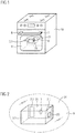
- FIG 1 illustrates a schematic perspective view of a cooker 10 with a monitoring device 3.1 on the front glass according to a preferred embodiment of the present invention.
- This example refers to a cooker 10 comprising a door handle 6.
- the monitoring device 3.1 is arranged on a (at least partially transparent) surface area 34 of the household, which is a glass panel 9 in this example.
- the monitoring device 3.1 comprises two fixation units 2.1, wherein a orienting section 31 is arranged relative to the fixation unit 2.1 in order to arrange the camera objective relative to the household appliance. Further, the orienting section 31 is, in a mounted state of the monitoring device 3.1 on the household appliance, arranged such that it is facing the predetermined monitoring region 32 of the household appliance.
- the orientation area 31 may be on the same side as the fixation units 2.1 or on the other side.
- the positioning of the fixation units 2.1 is variable and not bound to the showed position.
- the fixation unit(s) 2.1 may be a magnetic strips or a suction cup, a microscopic suction cup or micro suction foam or a hook and loop fastener (in this case with a respective counterpart on the appliance) for a flexible and easy fastening of the monitoring device 3.1 on the appliance.
- the fixation unit 2.1 is a micro suction foam for arranging the monitoring device 3.1 on the glass panel 9. By the suction foam, the monitoring device 3.1 is rotatable and it is therefore possible to arrange the device in different angles on the glass 9.
- the monitoring device can monitor the inside of the cooker 10 using the camera objective 1, which is arranged directly toward the oven glass 9.
- the monitoring device further comprises a communication device 23, e.g. an USB interface, which is connectable to an USB interface 7 on the door handle 6 for the communication or power supply via an USB-cable 8.
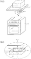
- FIG 3 illustrates a schematic perspective view of a metal cooker hood 11.1 with a monitoring device 3.2 according to another preferred embodiment of the present invention.
- the metal cooker hood 11.1 is arranged above a cooker 10 and comprises a monitoring device 3.2 on its underpart on the surface area 34 of the household appliance.
- the orientation section 31 it is possible to arrange or positioning the monitoring device 3.2 with the camera objective 1 relative to the cooking appliance 10.
- the camera objective 1 is arranged on the opposite side of the monitoring device 3.2 in relation to the metal cooker hood 11.1. It is therefore possible to monitor the hob of the cooker 10.
- a pot may be placed on the hob and the monitoring device 3.2 is arranged directly above the pot or in similar positions to monitor the cooking process in the pot.
- a user may receive the video signals from the monitoring device 3.2 and hence has an overview of the status of the food.
- the monitoring device 3.2 is releasable fixed on the metal cooker in the surface area 34 hood 11.1 by two fixation units 2.2.
- the monitoring device 3.2 may comprise a cover 4.1, which may be clipped on or off to the monitoring device 3.2 and may cover the monitoring device 3.2 against dirt, dust and the like.
- the cover 4.1 may also include or comprise a fixation unit 2.2.
- FIG 5 and 6 illustrate schematic perspective views of a cooking device 10 with a monitoring device according to another preferred embodiment of the present invention.
- the monitoring device 3.1 is arranged on the glass panel 9 on a surface area 34 by an orienting section 31.
- This orienting section 31 it is possible to arrange the monitor device relative to a monitoring region 32, which is a pan or the like.
- the monitoring device 3.1 is arranged such that is positionable by the orienting section 31 on a position on a distance d between the monitoring region 32 and the monitoring device 3.1. Further it is arranged such that is positionable by the orienting section 31 on a position on an angle ( ⁇ ) between the monitoring region 32 and the monitoring device 3.1.
- ⁇ angle
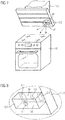
- FIG 7 illustrates a schematic perspective view of a glass cooker hood 11.2 with a monitoring device 3.3 according to another preferred embodiment of the present invention.
- the structure of the monitoring device 3.3 is similar to the embodiment 3.2 in FIG 3 and 4 .
- the monitoring device 3.3 is arranged on the cooker hood 11.2 on a surface area 34 in such an angle that it is aligned perfectly to the cooking hob of the cooker 10 for monitoring placed cooking pots.
- it may comprise two camera objectives (or lenses) 1.1 and 1.2 on the front and the back side of the monitoring device 3.3, so it is possible to use both sides of the device when fixing it on a surface.
- FIG 9 illustrates a schematic detailed perspective view of the glass cooker hood according to the preferred embodiment of the present invention.
- the monitoring device 3.2 is arranged on the cooker hood 11.1 by an orienting section 31.
- This orienting section 31 it is possible to arrange the monitor device relative to a monitoring region 32, which is in this example a pan or the like on a cooking hob 10.
- the monitoring device 3.2 is arranged such that is positionable by the orienting section 31 on a position on a distance d between the monitoring region 32 and the monitoring device 3.2. Further it is arranged such that is positionable by the orienting section 31 on a position on an angle ( ⁇ ) between the monitoring region 32 and the monitoring device 3.2.
- ⁇ angle
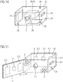
- FIG 10 illustrates a schematic perspective view of a monitoring device 3 according to a preferred embodiment of the present invention.
- the monitoring device 3 comprises within a housing 33 communication devices 20, 23, which may be a USB-interface or a Wi-Fi antenna and a camera unit 29.
- a recording device 28 is in conjunction with the camera objective 1 for monitoring the area to be monitored.
- the monitoring device 3 comprises further a rechargeable unit 21 (e.g. a battery or akku) which may be rechargeable via a power plug-in connector or the USB-interface. Further, it is possible to recharge the rechargeable unit 21 wireless via an inductive coil 22. An external inductive coil of the domestic appliance may be used for this kind of recharging.
- An indicator 26, preferably one or more LED, is also comprised by the monitoring device 3 to indicate the status of the rechargeable unit 21 or the charging status.
- the monitoring device 3 may be switched on and of a by a switch 25.
- FIG 11 illustrates further a schematic perspective view of a monitoring device 3 with a flap 4 according to a preferred embodiment of the present invention.
- a cover 4.1 is comprised by the monitoring device 3 in this embodiment.
- the flap 4 is releasable from the monitoring device 3 via swing opening and covers the camera objective 1 against dirt or the like.
- the flap 4 may comprise a protection lens 5, which is preferable transparent (e.g. glass or transparent plastics). Therefore it is possible to use the cover of the flap 4 while monitoring by the front side camera objective 1.1.
- the fixation unit 2 is a micro suction pad, which is arranged on the front side of the monitoring device 3.
- the fixation unit 2 is also covered by the flap 4, which has own fixation units 2.2 for the fixation of the monitoring device 3 on the surface area 34.
- the cover 4.1 is fixed on the backside of the monitoring device 3 while it is in use. After use, the cover 4.1 can be e.g. fixed on the front side for a covering of the camera objective 1.
- FIG 12 to 14 show holding devices 35 for several types of moni-toring devices. It is possible to use also tablets or smartphones (e.g. FIG 14 ) or ai-cameras (e.g. FIG 12, 13 ) or the like for the monitoring and thus there is no need for a specific monitoring device 3.
- a fastening 27 may be used, which is arranged on a fastening section 30, which may be a plain area.
- the monitoring devices 3 may be fastened on the fastening section 30, for example by fixation units 2.
- the orientation section 31 the monitoring device 3 may be positioning in the correct way according in above described ways. With such holding devices, the correct position and angle is always ensured for each domestic appliance.
Priority Applications (4)
| Application Number | Priority Date | Filing Date | Title |
|---|---|---|---|
| EP16198854.8A EP3321591B1 (de) | 2016-11-15 | 2016-11-15 | Überwachungsvorrichtung für haushaltsgeräte und haltevorrichtung |
| US16/347,958 US11619392B2 (en) | 2016-11-15 | 2017-11-10 | Monitoring device for household appliances and holding device |
| PCT/EP2017/078902 WO2018091369A1 (en) | 2016-11-15 | 2017-11-10 | Monitoring device for household appliances and holding device |
| AU2017362676A AU2017362676B2 (en) | 2016-11-15 | 2017-11-10 | Monitoring device for household appliances and holding device |
Applications Claiming Priority (1)
| Application Number | Priority Date | Filing Date | Title |
|---|---|---|---|
| EP16198854.8A EP3321591B1 (de) | 2016-11-15 | 2016-11-15 | Überwachungsvorrichtung für haushaltsgeräte und haltevorrichtung |
Publications (2)
| Publication Number | Publication Date |
|---|---|
| EP3321591A1 true EP3321591A1 (de) | 2018-05-16 |
| EP3321591B1 EP3321591B1 (de) | 2022-11-09 |
Family
ID=57321217
Family Applications (1)
| Application Number | Title | Priority Date | Filing Date |
|---|---|---|---|
| EP16198854.8A Active EP3321591B1 (de) | 2016-11-15 | 2016-11-15 | Überwachungsvorrichtung für haushaltsgeräte und haltevorrichtung |
Country Status (4)
| Country | Link |
|---|---|
| US (1) | US11619392B2 (de) |
| EP (1) | EP3321591B1 (de) |
| AU (1) | AU2017362676B2 (de) |
| WO (1) | WO2018091369A1 (de) |
Cited By (4)
| Publication number | Priority date | Publication date | Assignee | Title |
|---|---|---|---|---|
| WO2021094134A1 (de) * | 2019-11-12 | 2021-05-20 | Miele & Cie. Kg | Verfahren und system zur darstellung eines in einem gargerät durchgeführten garprozesses |
| EP3879182A1 (de) * | 2020-03-10 | 2021-09-15 | Electrolux Appliances Aktiebolag | Kameramodul |
| WO2022037886A1 (de) * | 2020-08-18 | 2022-02-24 | BSH Hausgeräte GmbH | Optisches ermitteln von betriebszuständen eines kochfelds |
| WO2023156009A1 (en) * | 2022-02-21 | 2023-08-24 | Electrolux Appliances Aktiebolag | Household appliance and operating method thereof |
Families Citing this family (1)
| Publication number | Priority date | Publication date | Assignee | Title |
|---|---|---|---|---|
| US10694882B2 (en) * | 2016-02-26 | 2020-06-30 | Zezhi Intellectual Property Service | Cooking device with image detection sensor |
Citations (4)
| Publication number | Priority date | Publication date | Assignee | Title |
|---|---|---|---|---|
| US20050092877A1 (en) * | 2003-10-31 | 2005-05-05 | Carnevali Jeffrey D. | Configurable mounting apparatus |
| EP2515044A1 (de) * | 2011-04-20 | 2012-10-24 | Miele & Cie. KG | Garsystem |
| DE102013206340A1 (de) * | 2013-04-10 | 2014-10-16 | E.G.O. Elektro-Gerätebau GmbH | Vorrichtung und Verfahren zur Steuerung eines Elektrogeräts |
| WO2015185211A2 (en) * | 2014-06-05 | 2015-12-10 | Ingo Stork Genannt Wersborg | Heat treatment monitoring system |
Family Cites Families (8)
| Publication number | Priority date | Publication date | Assignee | Title |
|---|---|---|---|---|
| DE102008041390A1 (de) * | 2008-08-20 | 2010-02-25 | BSH Bosch und Siemens Hausgeräte GmbH | Kochfeldvorrichtung |
| EP3212999A1 (de) * | 2014-10-30 | 2017-09-06 | Electrolux Home Products, Inc. | Verbesserte gerätediagnose mit sichtbaren indikatoren |
| JP6735513B2 (ja) * | 2016-06-15 | 2020-08-05 | パナソニックIpマネジメント株式会社 | 調理支援方法および調理支援システム |
| US10602035B2 (en) * | 2017-09-19 | 2020-03-24 | Google Llc | Temperature-controlled camera assembly |
| DE102018217811A1 (de) * | 2018-10-09 | 2020-04-09 | BSH Hausgeräte GmbH | Verfahren zum Behandeln von Gargut und Haushalts-Gargerät |
| DE102018217324A1 (de) * | 2018-10-10 | 2020-04-16 | BSH Hausgeräte GmbH | Gargerät mit Kamera und Verfahren zum Betreiben eines Gargeräts |
| DE102018221329A1 (de) * | 2018-12-10 | 2020-06-10 | BSH Hausgeräte GmbH | Verfahren zum Betreiben eines Haushalts-Gargeräts und Haushalts-Gargerät |
| DE102019200583A1 (de) * | 2018-12-21 | 2020-06-25 | BSH Hausgeräte GmbH | Gargerät und Verfahren zum Betreiben eines Gargeräts |
-
2016
- 2016-11-15 EP EP16198854.8A patent/EP3321591B1/de active Active
-
2017
- 2017-11-10 US US16/347,958 patent/US11619392B2/en active Active
- 2017-11-10 AU AU2017362676A patent/AU2017362676B2/en active Active
- 2017-11-10 WO PCT/EP2017/078902 patent/WO2018091369A1/en active Application Filing
Patent Citations (4)
| Publication number | Priority date | Publication date | Assignee | Title |
|---|---|---|---|---|
| US20050092877A1 (en) * | 2003-10-31 | 2005-05-05 | Carnevali Jeffrey D. | Configurable mounting apparatus |
| EP2515044A1 (de) * | 2011-04-20 | 2012-10-24 | Miele & Cie. KG | Garsystem |
| DE102013206340A1 (de) * | 2013-04-10 | 2014-10-16 | E.G.O. Elektro-Gerätebau GmbH | Vorrichtung und Verfahren zur Steuerung eines Elektrogeräts |
| WO2015185211A2 (en) * | 2014-06-05 | 2015-12-10 | Ingo Stork Genannt Wersborg | Heat treatment monitoring system |
Cited By (5)
| Publication number | Priority date | Publication date | Assignee | Title |
|---|---|---|---|---|
| WO2021094134A1 (de) * | 2019-11-12 | 2021-05-20 | Miele & Cie. Kg | Verfahren und system zur darstellung eines in einem gargerät durchgeführten garprozesses |
| EP3879182A1 (de) * | 2020-03-10 | 2021-09-15 | Electrolux Appliances Aktiebolag | Kameramodul |
| WO2021180554A1 (en) * | 2020-03-10 | 2021-09-16 | Electrolux Appliances Aktiebolag | Camera module |
| WO2022037886A1 (de) * | 2020-08-18 | 2022-02-24 | BSH Hausgeräte GmbH | Optisches ermitteln von betriebszuständen eines kochfelds |
| WO2023156009A1 (en) * | 2022-02-21 | 2023-08-24 | Electrolux Appliances Aktiebolag | Household appliance and operating method thereof |
Also Published As
| Publication number | Publication date |
|---|---|
| EP3321591B1 (de) | 2022-11-09 |
| AU2017362676A1 (en) | 2019-04-04 |
| US20190277509A1 (en) | 2019-09-12 |
| US11619392B2 (en) | 2023-04-04 |
| WO2018091369A1 (en) | 2018-05-24 |
| AU2017362676B2 (en) | 2023-06-15 |
Similar Documents
| Publication | Publication Date | Title |
|---|---|---|
| US11619392B2 (en) | Monitoring device for household appliances and holding device | |
| US11277546B2 (en) | Outdoor camera assembly | |
| EP3815059B1 (de) | Thermische verwaltung bei intelligenten türklingeln | |
| US9615007B2 (en) | Oven camera assembly | |
| KR102480312B1 (ko) | 단말기, 그와 통신하는 조리기기 및 조리기기의 제어 방법 | |
| CN107036389A (zh) | 一种智能化的冰箱内置摄像头监控系统 | |
| US20180202665A1 (en) | Oven | |
| CN110291331A (zh) | 带有能取出地构造的传感器模块的烹饪器具 | |
| CN206076634U (zh) | 电源线插头、电源线结构和电器设备 | |
| TWI736620B (zh) | 通訊用配件 | |
| EP2199715A2 (de) | Verfahren und Vorrichtung zum Austauschen einer Komponente | |
| US20100154172A1 (en) | Handle with docking station | |
| CN205985620U (zh) | 电源线插头、电源线结构和电器设备 | |
| CN208522773U (zh) | 基于WiFi、RF和红外信号的多功能网关 | |
| CN208817852U (zh) | 具有摄像头模块的冰箱 | |
| WO2019063305A1 (en) | COMMUNICATION MODULE FOR HOUSEHOLD APPLIANCE | |
| CN205897696U (zh) | 电冰箱 | |
| CA3210757A1 (en) | Media hub systems and methods | |
| CN205910513U (zh) | 云端网络智能家居自动控制系统 | |
| CN215258754U (zh) | 一种加热厨具摄像保护结构和智能煎烤机 | |
| CN206136075U (zh) | 一种壁式红外摄像装置 | |
| CN220190972U (zh) | 一种具有监控摄像功能的温控器 | |
| KR20210127263A (ko) | 로봇 | |
| CN219019277U (zh) | 一种家用电器 | |
| US20100157511A1 (en) | Adapter retrofit by replacement component |
Legal Events
| Date | Code | Title | Description |
|---|---|---|---|
| PUAI | Public reference made under article 153(3) epc to a published international application that has entered the european phase |
Free format text: ORIGINAL CODE: 0009012 |
|
| STAA | Information on the status of an ep patent application or granted ep patent |
Free format text: STATUS: THE APPLICATION HAS BEEN PUBLISHED |
|
| AK | Designated contracting states |
Kind code of ref document: A1 Designated state(s): AL AT BE BG CH CY CZ DE DK EE ES FI FR GB GR HR HU IE IS IT LI LT LU LV MC MK MT NL NO PL PT RO RS SE SI SK SM TR |
|
| AX | Request for extension of the european patent |
Extension state: BA ME |
|
| STAA | Information on the status of an ep patent application or granted ep patent |
Free format text: STATUS: REQUEST FOR EXAMINATION WAS MADE |
|
| 17P | Request for examination filed |
Effective date: 20181116 |
|
| RBV | Designated contracting states (corrected) |
Designated state(s): AL AT BE BG CH CY CZ DE DK EE ES FI FR GB GR HR HU IE IS IT LI LT LU LV MC MK MT NL NO PL PT RO RS SE SI SK SM TR |
|
| STAA | Information on the status of an ep patent application or granted ep patent |
Free format text: STATUS: EXAMINATION IS IN PROGRESS |
|
| 17Q | First examination report despatched |
Effective date: 20200219 |
|
| STAA | Information on the status of an ep patent application or granted ep patent |
Free format text: STATUS: EXAMINATION IS IN PROGRESS |
|
| STAA | Information on the status of an ep patent application or granted ep patent |
Free format text: STATUS: EXAMINATION IS IN PROGRESS |
|
| GRAP | Despatch of communication of intention to grant a patent |
Free format text: ORIGINAL CODE: EPIDOSNIGR1 |
|
| STAA | Information on the status of an ep patent application or granted ep patent |
Free format text: STATUS: GRANT OF PATENT IS INTENDED |
|
| INTG | Intention to grant announced |
Effective date: 20220107 |
|
| GRAJ | Information related to disapproval of communication of intention to grant by the applicant or resumption of examination proceedings by the epo deleted |
Free format text: ORIGINAL CODE: EPIDOSDIGR1 |
|
| STAA | Information on the status of an ep patent application or granted ep patent |
Free format text: STATUS: EXAMINATION IS IN PROGRESS |
|
| INTC | Intention to grant announced (deleted) | ||
| GRAP | Despatch of communication of intention to grant a patent |
Free format text: ORIGINAL CODE: EPIDOSNIGR1 |
|
| STAA | Information on the status of an ep patent application or granted ep patent |
Free format text: STATUS: GRANT OF PATENT IS INTENDED |
|
| INTG | Intention to grant announced |
Effective date: 20220601 |
|
| GRAS | Grant fee paid |
Free format text: ORIGINAL CODE: EPIDOSNIGR3 |
|
| GRAA | (expected) grant |
Free format text: ORIGINAL CODE: 0009210 |
|
| STAA | Information on the status of an ep patent application or granted ep patent |
Free format text: STATUS: THE PATENT HAS BEEN GRANTED |
|
| AK | Designated contracting states |
Kind code of ref document: B1 Designated state(s): AL AT BE BG CH CY CZ DE DK EE ES FI FR GB GR HR HU IE IS IT LI LT LU LV MC MK MT NL NO PL PT RO RS SE SI SK SM TR |
|
| REG | Reference to a national code |
Ref country code: GB Ref legal event code: FG4D |
|
| REG | Reference to a national code |
Ref country code: CH Ref legal event code: EP Ref country code: AT Ref legal event code: REF Ref document number: 1530603 Country of ref document: AT Kind code of ref document: T Effective date: 20221115 |
|
| REG | Reference to a national code |
Ref country code: DE Ref legal event code: R096 Ref document number: 602016076182 Country of ref document: DE |
|
| REG | Reference to a national code |
Ref country code: IE Ref legal event code: FG4D |
|
| REG | Reference to a national code |
Ref country code: LT Ref legal event code: MG9D |
|
| REG | Reference to a national code |
Ref country code: NL Ref legal event code: MP Effective date: 20221109 |
|
| REG | Reference to a national code |
Ref country code: AT Ref legal event code: MK05 Ref document number: 1530603 Country of ref document: AT Kind code of ref document: T Effective date: 20221109 |
|
| PG25 | Lapsed in a contracting state [announced via postgrant information from national office to epo] |
Ref country code: SE Free format text: LAPSE BECAUSE OF FAILURE TO SUBMIT A TRANSLATION OF THE DESCRIPTION OR TO PAY THE FEE WITHIN THE PRESCRIBED TIME-LIMIT Effective date: 20221109 Ref country code: PT Free format text: LAPSE BECAUSE OF FAILURE TO SUBMIT A TRANSLATION OF THE DESCRIPTION OR TO PAY THE FEE WITHIN THE PRESCRIBED TIME-LIMIT Effective date: 20230309 Ref country code: NO Free format text: LAPSE BECAUSE OF FAILURE TO SUBMIT A TRANSLATION OF THE DESCRIPTION OR TO PAY THE FEE WITHIN THE PRESCRIBED TIME-LIMIT Effective date: 20230209 Ref country code: LT Free format text: LAPSE BECAUSE OF FAILURE TO SUBMIT A TRANSLATION OF THE DESCRIPTION OR TO PAY THE FEE WITHIN THE PRESCRIBED TIME-LIMIT Effective date: 20221109 Ref country code: FI Free format text: LAPSE BECAUSE OF FAILURE TO SUBMIT A TRANSLATION OF THE DESCRIPTION OR TO PAY THE FEE WITHIN THE PRESCRIBED TIME-LIMIT Effective date: 20221109 Ref country code: ES Free format text: LAPSE BECAUSE OF FAILURE TO SUBMIT A TRANSLATION OF THE DESCRIPTION OR TO PAY THE FEE WITHIN THE PRESCRIBED TIME-LIMIT Effective date: 20221109 Ref country code: AT Free format text: LAPSE BECAUSE OF FAILURE TO SUBMIT A TRANSLATION OF THE DESCRIPTION OR TO PAY THE FEE WITHIN THE PRESCRIBED TIME-LIMIT Effective date: 20221109 |
|
| PG25 | Lapsed in a contracting state [announced via postgrant information from national office to epo] |
Ref country code: RS Free format text: LAPSE BECAUSE OF FAILURE TO SUBMIT A TRANSLATION OF THE DESCRIPTION OR TO PAY THE FEE WITHIN THE PRESCRIBED TIME-LIMIT Effective date: 20221109 Ref country code: PL Free format text: LAPSE BECAUSE OF FAILURE TO SUBMIT A TRANSLATION OF THE DESCRIPTION OR TO PAY THE FEE WITHIN THE PRESCRIBED TIME-LIMIT Effective date: 20221109 Ref country code: LV Free format text: LAPSE BECAUSE OF FAILURE TO SUBMIT A TRANSLATION OF THE DESCRIPTION OR TO PAY THE FEE WITHIN THE PRESCRIBED TIME-LIMIT Effective date: 20221109 Ref country code: IS Free format text: LAPSE BECAUSE OF FAILURE TO SUBMIT A TRANSLATION OF THE DESCRIPTION OR TO PAY THE FEE WITHIN THE PRESCRIBED TIME-LIMIT Effective date: 20230309 Ref country code: HR Free format text: LAPSE BECAUSE OF FAILURE TO SUBMIT A TRANSLATION OF THE DESCRIPTION OR TO PAY THE FEE WITHIN THE PRESCRIBED TIME-LIMIT Effective date: 20221109 Ref country code: GR Free format text: LAPSE BECAUSE OF FAILURE TO SUBMIT A TRANSLATION OF THE DESCRIPTION OR TO PAY THE FEE WITHIN THE PRESCRIBED TIME-LIMIT Effective date: 20230210 |
|
| PG25 | Lapsed in a contracting state [announced via postgrant information from national office to epo] |
Ref country code: NL Free format text: LAPSE BECAUSE OF FAILURE TO SUBMIT A TRANSLATION OF THE DESCRIPTION OR TO PAY THE FEE WITHIN THE PRESCRIBED TIME-LIMIT Effective date: 20221109 |
|
| REG | Reference to a national code |
Ref country code: CH Ref legal event code: PL |
|
| REG | Reference to a national code |
Ref country code: BE Ref legal event code: MM Effective date: 20221130 |
|
| PG25 | Lapsed in a contracting state [announced via postgrant information from national office to epo] |
Ref country code: SM Free format text: LAPSE BECAUSE OF FAILURE TO SUBMIT A TRANSLATION OF THE DESCRIPTION OR TO PAY THE FEE WITHIN THE PRESCRIBED TIME-LIMIT Effective date: 20221109 Ref country code: RO Free format text: LAPSE BECAUSE OF FAILURE TO SUBMIT A TRANSLATION OF THE DESCRIPTION OR TO PAY THE FEE WITHIN THE PRESCRIBED TIME-LIMIT Effective date: 20221109 Ref country code: LI Free format text: LAPSE BECAUSE OF NON-PAYMENT OF DUE FEES Effective date: 20221130 Ref country code: EE Free format text: LAPSE BECAUSE OF FAILURE TO SUBMIT A TRANSLATION OF THE DESCRIPTION OR TO PAY THE FEE WITHIN THE PRESCRIBED TIME-LIMIT Effective date: 20221109 Ref country code: DK Free format text: LAPSE BECAUSE OF FAILURE TO SUBMIT A TRANSLATION OF THE DESCRIPTION OR TO PAY THE FEE WITHIN THE PRESCRIBED TIME-LIMIT Effective date: 20221109 Ref country code: CZ Free format text: LAPSE BECAUSE OF FAILURE TO SUBMIT A TRANSLATION OF THE DESCRIPTION OR TO PAY THE FEE WITHIN THE PRESCRIBED TIME-LIMIT Effective date: 20221109 Ref country code: CH Free format text: LAPSE BECAUSE OF NON-PAYMENT OF DUE FEES Effective date: 20221130 |
|
| P01 | Opt-out of the competence of the unified patent court (upc) registered |
Effective date: 20230625 |
|
| REG | Reference to a national code |
Ref country code: DE Ref legal event code: R097 Ref document number: 602016076182 Country of ref document: DE |
|
| PG25 | Lapsed in a contracting state [announced via postgrant information from national office to epo] |
Ref country code: SK Free format text: LAPSE BECAUSE OF FAILURE TO SUBMIT A TRANSLATION OF THE DESCRIPTION OR TO PAY THE FEE WITHIN THE PRESCRIBED TIME-LIMIT Effective date: 20221109 Ref country code: LU Free format text: LAPSE BECAUSE OF NON-PAYMENT OF DUE FEES Effective date: 20221115 Ref country code: AL Free format text: LAPSE BECAUSE OF FAILURE TO SUBMIT A TRANSLATION OF THE DESCRIPTION OR TO PAY THE FEE WITHIN THE PRESCRIBED TIME-LIMIT Effective date: 20221109 |
|
| PLBE | No opposition filed within time limit |
Free format text: ORIGINAL CODE: 0009261 |
|
| STAA | Information on the status of an ep patent application or granted ep patent |
Free format text: STATUS: NO OPPOSITION FILED WITHIN TIME LIMIT |
|
| 26N | No opposition filed |
Effective date: 20230810 |
|
| GBPC | Gb: european patent ceased through non-payment of renewal fee |
Effective date: 20230209 |
|
| PG25 | Lapsed in a contracting state [announced via postgrant information from national office to epo] |
Ref country code: IE Free format text: LAPSE BECAUSE OF NON-PAYMENT OF DUE FEES Effective date: 20221115 |
|
| PG25 | Lapsed in a contracting state [announced via postgrant information from national office to epo] |
Ref country code: SI Free format text: LAPSE BECAUSE OF FAILURE TO SUBMIT A TRANSLATION OF THE DESCRIPTION OR TO PAY THE FEE WITHIN THE PRESCRIBED TIME-LIMIT Effective date: 20221109 Ref country code: BE Free format text: LAPSE BECAUSE OF NON-PAYMENT OF DUE FEES Effective date: 20221130 |
|
| PG25 | Lapsed in a contracting state [announced via postgrant information from national office to epo] |
Ref country code: GB Free format text: LAPSE BECAUSE OF NON-PAYMENT OF DUE FEES Effective date: 20230209 |
|
| PG25 | Lapsed in a contracting state [announced via postgrant information from national office to epo] |
Ref country code: GB Free format text: LAPSE BECAUSE OF NON-PAYMENT OF DUE FEES Effective date: 20230209 |
|
| PGFP | Annual fee paid to national office [announced via postgrant information from national office to epo] |
Ref country code: IT Payment date: 20231124 Year of fee payment: 8 Ref country code: FR Payment date: 20231123 Year of fee payment: 8 Ref country code: DE Payment date: 20231127 Year of fee payment: 8 |
|
| PG25 | Lapsed in a contracting state [announced via postgrant information from national office to epo] |
Ref country code: HU Free format text: LAPSE BECAUSE OF FAILURE TO SUBMIT A TRANSLATION OF THE DESCRIPTION OR TO PAY THE FEE WITHIN THE PRESCRIBED TIME-LIMIT; INVALID AB INITIO Effective date: 20161115 |