EP3321589A1 - Treibstoffdüse einer gasturbine mit drallerzeuger - Google Patents
Treibstoffdüse einer gasturbine mit drallerzeuger Download PDFInfo
- Publication number
- EP3321589A1 EP3321589A1 EP17200868.2A EP17200868A EP3321589A1 EP 3321589 A1 EP3321589 A1 EP 3321589A1 EP 17200868 A EP17200868 A EP 17200868A EP 3321589 A1 EP3321589 A1 EP 3321589A1
- Authority
- EP
- European Patent Office
- Prior art keywords
- region
- annular channel
- fuel nozzle
- guide elements
- inflow
- Prior art date
- Legal status (The legal status is an assumption and is not a legal conclusion. Google has not performed a legal analysis and makes no representation as to the accuracy of the status listed.)
- Granted
Links
Images




Classifications
-
- F—MECHANICAL ENGINEERING; LIGHTING; HEATING; WEAPONS; BLASTING
- F23—COMBUSTION APPARATUS; COMBUSTION PROCESSES
- F23D—BURNERS
- F23D11/00—Burners using a direct spraying action of liquid droplets or vaporised liquid into the combustion space
- F23D11/10—Burners using a direct spraying action of liquid droplets or vaporised liquid into the combustion space the spraying being induced by a gaseous medium, e.g. water vapour
- F23D11/106—Burners using a direct spraying action of liquid droplets or vaporised liquid into the combustion space the spraying being induced by a gaseous medium, e.g. water vapour medium and fuel meeting at the burner outlet
- F23D11/107—Burners using a direct spraying action of liquid droplets or vaporised liquid into the combustion space the spraying being induced by a gaseous medium, e.g. water vapour medium and fuel meeting at the burner outlet at least one of both being subjected to a swirling motion
-
- B—PERFORMING OPERATIONS; TRANSPORTING
- B05—SPRAYING OR ATOMISING IN GENERAL; APPLYING FLUENT MATERIALS TO SURFACES, IN GENERAL
- B05B—SPRAYING APPARATUS; ATOMISING APPARATUS; NOZZLES
- B05B1/00—Nozzles, spray heads or other outlets, with or without auxiliary devices such as valves, heating means
- B05B1/34—Nozzles, spray heads or other outlets, with or without auxiliary devices such as valves, heating means designed to influence the nature of flow of the liquid or other fluent material, e.g. to produce swirl
- B05B1/3405—Nozzles, spray heads or other outlets, with or without auxiliary devices such as valves, heating means designed to influence the nature of flow of the liquid or other fluent material, e.g. to produce swirl to produce swirl
- B05B1/341—Nozzles, spray heads or other outlets, with or without auxiliary devices such as valves, heating means designed to influence the nature of flow of the liquid or other fluent material, e.g. to produce swirl to produce swirl before discharging the liquid or other fluent material, e.g. in a swirl chamber upstream the spray outlet
- B05B1/3421—Nozzles, spray heads or other outlets, with or without auxiliary devices such as valves, heating means designed to influence the nature of flow of the liquid or other fluent material, e.g. to produce swirl to produce swirl before discharging the liquid or other fluent material, e.g. in a swirl chamber upstream the spray outlet with channels emerging substantially tangentially in the swirl chamber
-
- F—MECHANICAL ENGINEERING; LIGHTING; HEATING; WEAPONS; BLASTING
- F02—COMBUSTION ENGINES; HOT-GAS OR COMBUSTION-PRODUCT ENGINE PLANTS
- F02C—GAS-TURBINE PLANTS; AIR INTAKES FOR JET-PROPULSION PLANTS; CONTROLLING FUEL SUPPLY IN AIR-BREATHING JET-PROPULSION PLANTS
- F02C7/00—Features, components parts, details or accessories, not provided for in, or of interest apart form groups F02C1/00 - F02C6/00; Air intakes for jet-propulsion plants
- F02C7/22—Fuel supply systems
- F02C7/222—Fuel flow conduits, e.g. manifolds
-
- F—MECHANICAL ENGINEERING; LIGHTING; HEATING; WEAPONS; BLASTING
- F23—COMBUSTION APPARATUS; COMBUSTION PROCESSES
- F23C—METHODS OR APPARATUS FOR COMBUSTION USING FLUID FUEL OR SOLID FUEL SUSPENDED IN A CARRIER GAS OR AIR
- F23C7/00—Combustion apparatus characterised by arrangements for air supply
- F23C7/002—Combustion apparatus characterised by arrangements for air supply the air being submitted to a rotary or spinning motion
- F23C7/004—Combustion apparatus characterised by arrangements for air supply the air being submitted to a rotary or spinning motion using vanes
-
- F—MECHANICAL ENGINEERING; LIGHTING; HEATING; WEAPONS; BLASTING
- F23—COMBUSTION APPARATUS; COMBUSTION PROCESSES
- F23R—GENERATING COMBUSTION PRODUCTS OF HIGH PRESSURE OR HIGH VELOCITY, e.g. GAS-TURBINE COMBUSTION CHAMBERS
- F23R3/00—Continuous combustion chambers using liquid or gaseous fuel
- F23R3/02—Continuous combustion chambers using liquid or gaseous fuel characterised by the air-flow or gas-flow configuration
- F23R3/04—Air inlet arrangements
- F23R3/10—Air inlet arrangements for primary air
- F23R3/12—Air inlet arrangements for primary air inducing a vortex
- F23R3/14—Air inlet arrangements for primary air inducing a vortex by using swirl vanes
-
- F—MECHANICAL ENGINEERING; LIGHTING; HEATING; WEAPONS; BLASTING
- F05—INDEXING SCHEMES RELATING TO ENGINES OR PUMPS IN VARIOUS SUBCLASSES OF CLASSES F01-F04
- F05D—INDEXING SCHEME FOR ASPECTS RELATING TO NON-POSITIVE-DISPLACEMENT MACHINES OR ENGINES, GAS-TURBINES OR JET-PROPULSION PLANTS
- F05D2220/00—Application
- F05D2220/30—Application in turbines
- F05D2220/32—Application in turbines in gas turbines
Definitions
- the invention relates to a swirl generator of a fuel nozzle of a gas turbine and to a provided with the swirl generator fuel nozzle.
- the term gas turbine is understood to mean both aircraft gas turbine engines and stationary gas turbines.
- a plurality of fuel nozzles are provided, which are each surrounded at their outflow by a swirl generator.
- the swirl generator is of annular design and usually has two annular channels, through which air is supplied into the combustion chamber of the combustion chamber. In each annular channel distributed around the circumference air guide elements are provided, which lead to a twisting of the incoming air. With two ring channels, the twisting takes place with different twisting angles.
- the air guide elements are designed as sheet-like or contoured blades and reduce or limit the respective amount of air that can flow through the annular channel, by the blocking effect by their radial extent over the channel height and its thickness.
- a predetermined radial height of the respective annular channel which is largely determined by the outer diameter of the fuel nozzle and / or the inner diameter of the burner seal, thus the effective flow area of the annular channel is structurally predetermined. This in turn leads to the limitation of the amount of air that can be supplied to the combustion chamber.
- In order to introduce additional air into the combustion chamber according to the previously known from the prior art constructions only the possibility of radially increasing the swirl generator and / or the main body of the fuel nozzle.
- the Fuel nozzle with its swirl generator not very flexible, if, for example, to avoid soot emissions, larger amounts of air to be introduced into the combustion chamber.
- the invention has for its object to provide a swirl generator of a fuel nozzle and provided with a swirl generator fuel nozzle, which allow for a simple design and simple, cost manufacturability, the supply of a larger amount of air into the combustion chamber.
- the invention thus provides that it comprises an outer and an inner ring element, wherein the two ring elements are arranged concentrically to one another. Between the inner ring member and the outer ring member an outer annular channel is formed. Accordingly, when the swirl generator is mounted on the fuel nozzle, an inner annular channel is defined between the main body of the fuel nozzle and the inner ring member. According to the invention, at least one of the annular channels has at its inflow region a radial height which is greater than a radial height of a central region of the annular channel. According to the invention, the air guide elements are provided for generating the twist in the inflow region with the larger radial height.
- the cross section of the outer annular channel tapers from the inflow region to the outflow region.
- the annular channel is thus constructed nozzle-like.
- the inventive solution it is possible to maintain the same number of the number of air guide elements in the annular channels, which lead to the twisting of the incoming air, as in the respective underlying state of the art.
- a sufficient twisting of the air can be achieved with increased total air quantity.
- the effective flow area in the inflow area of the outer and / or the inner annular channel is greater than the effective flow area in an axially middle area of the respective annular channel.
- annular channels which, as mentioned above, are tapered over their axial length, the resulting differences to the effective flow area in the inflow region may vary to a respective cross-sectional area.
- the taper of the annular channels can according to the invention either run continuously, but it is also a step-like cross-sectional change possible.
- the walls of the annular channels according to the invention may be formed like a circular arc or ellipse-like with respect to their cross-section, resulting in toroidal wall courses of the annular channels, which lead to the mentioned cross-sectional taper and thus reduce the flow area between the inflow and a central region.
- inflow regions of the annular channels in the axial direction or to align them at an angle to the axial direction. It is also possible to align the inflow areas and the resulting openings in the radial direction.
- the gas turbine engine 110 is a generalized example of a turbomachine, in which the invention can be applied.
- the engine 110 is formed in a conventional manner and comprises in succession an air inlet 111, a fan 112 circulating in a housing, a medium pressure compressor 113, a high pressure compressor 114, a combustion chamber 115, a high pressure turbine 116, a medium pressure turbine 117 and a low pressure turbine 118 and a Exhaust nozzle 119, which are all arranged around a central engine center axis 101.
- the intermediate pressure compressor 113 and the high pressure compressor 114 each include a plurality of stages, each of which includes a circumferentially extending array of fixed stationary vanes 120, commonly referred to as stator vanes, that radially inwardly from the core engine housing 121 into an annular flow passage through the compressors 113, 114 protrude.
- the compressors further include an array of compressor blades 122 projecting radially outward from a rotatable drum or disc 125 coupled to hubs 126 of high pressure turbine 116 and intermediate pressure turbine 117, respectively.
- the turbine sections 116, 117, 118 have similar stages, comprising an array of fixed vanes 123 projecting radially inward from the housing 121 into the annular flow passage through the turbines 116, 117, 118, and a downstream array of turbine blades 124 projecting outwardly from a rotatable hub 126.
- FIGS. 2 and 3 show constructions according to the prior art, which results in the underlying structure of a fuel nozzle and an associated swirl generator.
- the illustrations are each shown in an axial section plane, which comprises a central axis 26 of a fuel nozzle 6 or of a main body of the fuel nozzle.
- the figure shows a simplified view A according to FIG. 2 ,
- the Figures 2 and 3 thus, in the sectional view of a 3-stream fuel nozzle 6 according to the prior art. This construction results from the publications mentioned above.
- the Figures 2 and 3 further clarify the arrangement of the fuel nozzle 6 in a combustion chamber 115 of the gas turbine.
- the combustion chamber has a combustion chamber head 2 in the usual design, which is provided with a respective opening through which the fuel nozzle 6 is mounted and which is dimensioned so that an air flow 19 can flow through the combustion chamber head.
- a combustion chamber 4 is shown, which is bounded by a head plate 3 frontally.
- a burner seal 7 is formed on the top plate 3.
- the supplied air flows from a high-pressure compressor, not shown, through a diffuser 1 in the direction of the combustion chamber head 2 and subsequently, as mentioned, through a recess of the combustion chamber head as air flow 19 in the intermediate region between the combustion chamber head 2 and the top plate 3.
- the main body of the fuel nozzle 6 is with a centric air channel 17 (see FIG. FIGS. 4 to 7 ), through which a part of the total volume of air is conducted into the combustion chamber 4.
- the fuel nozzle 6 is fixed to an outer case 5 and protrudes into the combustion chamber 4 through the burner seal 7.
- the aforementioned burner seal 7 forms a seal between the top plate 3 and the swirler 25 surrounding the main body of the fuel nozzle 6.
- the fuel nozzle 6 has a shaft 8 through which a fuel supply 9 takes place.
- the fuel is passed through the supply line 9 in a circumferential chamber 12 and subsequently flows through fuel channels 13 to an injection nozzle 14.
- FIG. 2 While in FIG. 2 the three air ducts 10 of the three-stream fuel nozzle are provided with the same reference numerals, illustrates the FIG. 3 in that, in addition to the centric air channel 17, two further concentric annular channels are formed by the swirl generator 25, namely an outer annular channel 18a and an inner annular channel 18b. These annular channels 18a and 18b are defined by an outer ring element 21 and inner ring element 22.
- FIG. 3 shows that in the inflow region 23 of the annular channels 18a and 18b each air guide elements 11 are arranged. These are evenly distributed around the circumference, as can be seen from view A of the FIG. 2 results. To illustrate the invention is in the schematic representation of the view A of FIG. 2 only the outer annular channel 18a is shown with the air guide elements 11 arranged therein.
- FIG. 3 shows that a radial height h of the outer annular channel extends substantially over the entire axial length of the outer annular channel 18a, so that the effective flow area is determined by the radial height h minus the cross-sectional areas of the air guide elements 11, as in view A of FIG. 2 is clarified.
- the air guide elements 11 each have a thickness D and a number N and extend over the entire height h of the outer annular channel 18a.
- the air guide elements 11 block the free cross section of the outer annular channel 18a and lead to a reduced amount of air which can flow through the annular channel.
- FIG. 3 shows that a radial height h of the outer annular channel extends substantially over the entire axial length of the outer annular channel 18a, so that the effective flow area is determined by the radial height h minus the cross-sectional areas of the air guide elements 11, as in view A of FIG. 2 is clarified.
- the air passages 18a and 18b extend in the axial direction, the course of the annular passages being cylindrical.
- the narrowest cross section of the respective annular channels thus results in the area of the air guiding elements (swirl elements) 11.
- FIGS. 4 to 7 each show embodiments of the invention, wherein the representation respectively analog FIG. 3 he follows. Identical parts are each provided with the same reference numerals.
- the narrowest cross section of the outer annular channel 18a and the inner annular channel 18b results by the radial height h of the respective annular channel.
- the air guiding elements 11 are arranged upstream of this narrowest cross section h and are combined with a larger radial height H of the respective annular channel.
- the channel height H is selected as a multiple X of the channel height h such that the effective flow area A in the area of the air guide elements 11 is greater than the flow area defined by the channel height h and the mean radius r in the region of the channel height h.
- the flow area a in the inflow region 23 thus results from the air guide elements 11 arranged there, from the radius R present there (average radius in the area of the air guide elements 11), the radial channel height H and the surface blocked by the air guide elements 11, which the number, the Thickness and the height of the air guide elements 11 considered:
- A 2 ⁇ ⁇ ⁇ R ⁇ H - N ⁇ G ⁇ D ,
- the annular channels are dimensioned so that there is a significant increase in the amount of air to be carried out, for example by up to 100%.
- the two annular channels 18a and 18b In order to realize an enlarged in diameter inflow region 23, it is necessary to dimension the two annular channels 18a and 18b in a suitable manner. This is done by enlarging the outer diameter of the swirl generator 25 upstream of the head plate 3 in order to realize the channel height H there.
- the shape of the outer annular channel 18a and the inner annular channel 18b is selected according to the invention so that the respective annular channel of the channel height H from the trailing edge of the air guide 11 tapers to the narrowest channel height h. This is achieved by appropriate embodiments of the outer ring member 21 and the inner ring member 22.
- FIGS. 4 to 7 differ with regard to the configuration and the course of the respective annular channels 18a and 18b or the shape of the ring elements 21 and 22nd
- an embodiment of the inflow region 23 results in an axially parallel arrangement, so that both annular channels 18a and 18b are arranged with the air guide elements 11 provided there in the respective inflow region 23 in the axial direction.
- a respective outflow region 24 is dimensioned in a conventional manner in order to adapt the twisted air flow to the air flow through the centric air channel 17 and the fuel jet emerging from the injection nozzle 14. This is known from the prior art and need not be further described at this point.
- a transition occurs between the individual cross-sectional areas with a substantially rounded shape.
- the FIG. 5 shows an embodiment in which each rectilinear, based on the sectional view of FIG.
- Wall regions of the ring members 21 and 22 are provided, so that there is a gradual reduction of the cross-sectional area.
- the inflow region 23 is arranged at an angle to the central axis 26, the walls are provided with a circular arc-like or elliptical cross-sectional area.
- the inflow region 23 of the outer annular channel 18a is positioned in the radial direction.
- the axial length of the swirl generator 25 and the fuel nozzle 6 compared to the prior art according to the invention is the same, so that no structural changes of the combustion chamber, in particular the combustion chamber head 2 are required.
Landscapes
- Engineering & Computer Science (AREA)
- Chemical & Material Sciences (AREA)
- Combustion & Propulsion (AREA)
- Mechanical Engineering (AREA)
- General Engineering & Computer Science (AREA)
- Spray-Type Burners (AREA)
Abstract
Description
- Die Erfindung bezieht sich auf einen Drallerzeuger einer Treibstoffdüse einer Gasturbine sowie auf eine mit dem Drallerzeuger versehene Treibstoffdüse.
- Aus dem Stand der Technik ist es bekannt, Treibstoffdüsen im Bereich einer Kopfplatte einer Brennkammer einer Gasturbine anzuordnen, um zum einen Treibstoff einzuspritzen und um zum anderen die Möglichkeit einer Lufteinleitung in den Innenraum der Brennkammer zu schaffen. Im Rahmen der Erfindung werden unter dem Begriff Gasturbine sowohl Fluggasturbinen-Triebwerke als auch stationäre Gasturbinen verstanden. Bei einer Ringbrennkammer sind um den Umfang verteilt mehrere Treibstoffdüsen vorgesehen, welche jeweils an ihrem Ausströmbereich von einem Drallerzeuger umgeben sind. Der Drallerzeuger ist ringartig ausgebildet und weist üblicherweise zwei Ringkanäle auf, durch welche Luft in den Brennraum der Brennkammer zugeführt wird. In jedem Ringkanal sind um den Umfang verteilt Luftleitelemente vorgesehen, welche zu einer Verdrallung der einströmenden Luft führen. Bei zwei Ringkanälen erfolgt die Verdrallung mit unterschiedlichen Verdrallungswinkeln.
- Die Luftleitelemente sind blechartig oder als konturierte Schaufeln ausgestaltet und verringern oder limitieren die jeweilige Luftmenge, welche durch den Ringkanal strömen kann, durch die verblockende Wirkung durch ihre radiale Ausdehnung über die Kanalhöhe und ihre Dicke. Bei einer vorgegebenen radialen Höhe des jeweiligen Ringkanals, welche maßgeblich durch den Außendurchmesser der Treibstoffdüse und/oder den Innendurchmesser der Brennerdichtung vorgegeben wird, ist somit die effektive Strömungsfläche des Ringkanals konstruktiv vorgegeben. Dies wiederum führt zu der Limitierung der Luftmenge, welche der Brennkammer zugeführt werden kann. Um zusätzliche Luft in die Brennkammer einzuleiten, ergibt sich nach den aus dem Stand der Technik vorbekannten Konstruktionen nur die Möglichkeit, den Drallerzeuger und/oder den Hauptkörper der Treibstoffdüse radial zu vergrößern. Dies führt zum einen zu einem größeren benötigten Bauraum und bedingt andererseits ein höheres Gesamtgewicht. Somit ist die Treibstoffdüse mit ihrem Drallerzeuger nicht sehr flexibel einsetzbar, wenn, bspw. zur Vermeidung von Rußemissionen, größere Luftmengen in den Brennraum eingeleitet werden sollen.
- Zum Stand der Technik wird auf die
US 6,883,332 B2 , dieUS 2002/0162335 A1 , dieUS 6,547,163 B1 oder dieUS 6,560,964 B2 verwiesen. - Der Erfindung liegt die Aufgabe zugrunde, einen Drallerzeuger einer Treibstoffdüse und eine mit einem Drallerzeuger versehene Treibstoffdüse zu schaffen, welche bei einfachem Aufbau und einfacher, kostengünstiger Herstellbarkeit die Zuführung einer größeren Luftmenge in die Brennkammer ermöglichen.
- Erfindungsgemäß wird die Aufgabe durch die Merkmalskombinationen der unabhängigen Ansprüche gelöst, die jeweiligen Unteransprüche zeigen weitere vorteilhafte Ausgestaltungen der Erfindung.
- Hinsichtlich des Drallerzeugers ist erfindungsgemäß somit vorgesehen, dass dieser ein äußeres und ein inneres Ringelement umfasst, wobei die beiden Ringelemente konzentrisch zueinander angeordnet sind. Zwischen dem inneren Ringelement und dem äußeren Ringelement ist ein äußerer Ringkanal gebildet. Entsprechend wird bei an der Treibstoffdüse montiertem Drallerzeuger zwischen dem Hauptkörper der Treibstoffdüse und dem inneren Ringelement ein innerer Ringkanal definiert. Erfindungsgemäß ist vorgesehen, dass zumindest einer der Ringkanäle an seinem Einströmbereich eine radiale Höhe aufweist, welche größer ist, als eine radiale Höhe eines mittleren Bereichs des Ringkanals. Erfindungsgemäß sind die Luftleitelemente zur Erzeugung des Dralls in dem Einströmbereich mit der größeren radialen Höhe vorgesehen.
- Bei geeigneter Dimensionierung und Auswahl der jeweiligen radialen Höhen des äußeren bzw. des inneren Ringkanals ergibt sich somit im Einströmbereich eine erheblich vergrößerte Strömungsfläche des Ringkanals, sodass trotz der im Einströmbereich angeordneten Luftleitelemente eine wesentlich größere Luftmenge zuströmen kann. Es ist erfindungsgemäß dabei nicht erforderlich, die Treibstoffdüse selbst zu verändern. Vielmehr kann mit der Erfindung bei einer vorhandenen Treibstoffdüse durch die Ausgestaltung des Drallerzeugers eine Erhöhung der Luftvolumina erreicht werden. Alternativ hierzu ist es möglich, eine im Durchmesser kleinere Treibstoffdüse bei gleichbleibenden Außenabmessungen des Drallerzeugers zu verwenden, um eine höhere Luftmenge in die Brennkammer zu leiten. Bei der letzteren Variante ist es möglich, das Gesamtgewicht der Treibstoffdüsen und des zugehörigen Drallerzeugers erheblich zu verringern. Bei beiden Varianten ist es möglich, die doppelte Luftmenge oder mehr, verglichen mit dem Stand der Technik, zuzuführen.
- Es ist weiterhin vorgesehen, dass der Querschnitt des äußeren Ringkanals sich vom Einströmbereich zum Ausströmbereich verjüngt. Der Ringkanal ist somit düsenartig aufgebaut. Gleiches gilt für den inneren Ringkanal, welcher zwischen dem Hauptkörper der Treibstoffdüse und dem radial inneren Ringelement definiert wird.
- Durch die erfindungsgemäße Lösung ist es möglich, die Anzahl der Luftleitelemente in den Ringkanälen, welche zur Verdrallung der zuströmenden Luft führen, in gleicher Anzahl beizubehalten, wie bei dem jeweils zugrunde liegenden Stand der Technik. Somit kann eine ausreichende Verdrallung der Luft bei gesteigerter Gesamt-Luftmenge erreicht werden.
- Zur Verdeutlichung der Erfindung ist nochmals darauf hinzuweisen, dass die effektive Strömungsfläche im Einströmbereich des äußeren bzw. des inneren Ringkanals erfindungsgemäß größer ist, als die effektive Strömungsfläche in einem axial mittleren Bereich des jeweiligen Ringkanals. Es versteht sich, dass bei Ringkanälen, welche, wie oben erwähnt, über ihre axiale Länge verjüngt ausgebildet sind, die sich ergebenden Unterschiede zur effektiven Strömungsfläche im Einströmbereich zu einem jeweiligen Querschnittsbereich variieren kann. Zur Verdeutlichung der Erfindung wird deshalb auf einen axial mittleren Bereich Bezug genommen. Dabei ist festzuhalten, dass sich die Begriffe axial und radial jeweils auf eine Mittelachse der Treibstoffdüse bzw. des Hauptkörpers der Treibstoffdüse beziehen.
- Die Verjüngung der Ringkanäle kann erfindungsgemäß entweder kontinuierlich verlaufen, es ist jedoch auch eine stufenartige Querschnittsveränderung möglich. Weiterhin können die Wandungen der Ringkanäle erfindungsgemäß kreisbogenartig oder ellipsenartig hinsichtlich ihres Querschnitts ausgebildet sein, wodurch sich torusartige Wandverläufe der Ringkanäle ergeben, die zu der erwähnten Querschnittsverjüngung und damit Reduzierung der Durchströmungsfläche zwischen dem Einströmbereich und einem mittleren Bereich führen.
- Weiterhin ist es erfindungsgemäß möglich, die Einströmbereiche der Ringkanäle in Axialrichtung anzuordnen oder in einem Winkel zur Axialrichtung auszurichten. Es ist auch möglich, die Einströmbereiche und die sich damit ergebenden Öffnungen in Radialrichtung auszurichten.
- Um den erfindungsgemäßen Drallerzeuger bzw. die mit dem Drallerzeuger ausgerüstete Treibstoffdüse in eine bestehende Brennkammerkonstruktion einzupassen, kann es vorteilhaft sein, das äußere Ringelement stromauf der Kopfplatte und/oder der Brennerdichtung mit einem größeren Außendurchmesser zu versehen, als der Innendurchmesser der Brennerdichtung. Hierdurch ist es möglich, sowohl den Drallerzeuger selbst als auch die mit dem Drallerzeuger versehene Treibstoffdüse in üblicher Weise von der Seite des Brennkammerkopfes aus in die Brennerdichtung einzuführen und an der Kopfplatte zu lagern. Konstruktive Änderungen des Gesamtaufbaus der zu verwendenden Brennkammer sind somit nicht erforderlich. In entsprechender Weise kann selbstverständlich der Außendurchmesser des Einströmbereichs des inneren Ringelements, welches den inneren Ringkanal ausbildet, stromauf der Kopfplatte ebenfalls im Durchmesser vergrößert werden.
- Im Folgenden wird die Erfindung anhand von Ausführungsbeispielen in Verbindung mit der Zeichnung beschrieben. Dabei zeigt:
- Fig. 1
- ein Gasturbinentriebwerk zur Verwendung der Erfindung,
- Fig. 2
- eine vereinfachte Schnittansicht einer Treibstoffdüse mit Drallerzeuger gemäß dem Stand der Technik,
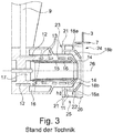
- Fig. 3
- eine vergrößerte Darstellung der Ansicht der
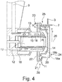
Fig. 2 gemäß dem Stand der Technik, - Fig. 4
- eine Schnittansicht, analog
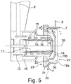
Fig. 3 , eines ersten Ausführungsbeispiels der Erfindung, - Fig. 5
- eine Schnittansicht, analog
Fig. 4 , eines weiteren Ausführungsbeispiels der Erfindung, - Fig. 6
- eine Schnittansicht, analog den
Figuren 4 und5 , eines dritten Ausführungsbeispiels der Erfindung, und - Fig. 7
- eine Schnittansicht eines weiteren Ausführungsbeispiels analog der Darstellung der
Figuren 4 bis 6 . - Das Gasturbinentriebwerk 110 gemäß
Fig. 1 ist ein allgemein dargestelltes Beispiel einer Turbomaschine, bei der die Erfindung Anwendung finden kann. Das Triebwerk 110 ist in herkömmlicher Weise ausgebildet und umfasst in Strömungsrichtung hintereinander einen Lufteinlass 111, einen in einem Gehäuse umlaufenden Fan 112, einen Mitteldruckkompressor 113, einen Hochdruckkompressor 114, eine Brennkammer 115, eine Hochdruckturbine 116, eine Mitteldruckturbine 117 und eine Niederdruckturbine 118 sowie eine Abgasdüse 119, die sämtlich um eine zentrale Triebwerksmittelachse 101 angeordnet sind. - Der Mitteldruckkompressor 113 und der Hochdruckkompressor 114 umfassen jeweils mehrere Stufen, von denen jede eine in Umfangsrichtung verlaufende Anordnung fester stationärer Leitschaufeln 120 aufweist, die allgemein als Statorschaufeln bezeichnet werden und die radial nach innen vom Kerntriebwerksgehäuse 121 in einen ringförmigen Strömungskanal durch die Kompressoren 113, 114 vorstehen. Die Kompressoren weisen weiter eine Anordnung von Kompressorlaufschaufeln 122 auf, die radial nach außen von einer drehbaren Trommel oder Scheibe 125 vorstehen, die mit Naben 126 der Hochdruckturbine 116 bzw. der Mitteldruckturbine 117 gekoppelt sind.
- Die Turbinenabschnitte 116, 117, 118 weisen ähnliche Stufen auf, umfassend eine Anordnung von festen Leitschaufeln 123, die radial nach innen vom Gehäuse 121 in den ringförmigen Strömungskanal durch die Turbinen 116, 117, 118 vorstehen, und eine nachfolgende Anordnung von Turbinenschaufeln 124, die nach außen von einer drehbaren Nabe 126 vorstehen. Die Kompressortrommel oder Kompressorscheibe 125 und die darauf angeordneten Schaufeln 122 sowie die Turbinenrotornabe 126 und die darauf angeordneten Turbinenlaufschaufeln 124 drehen sich im Betrieb um die Triebwerksmittelachse 101.
- Die
Figuren 2 und3 zeigen Konstruktionen gemäß dem Stand der Technik, aus denen sich der zugrunde liegende Aufbau einer Treibstoffdüse sowie eines zugeordneten Drallerzeugers ergibt. Die Darstellungen sind jeweils in einer Axialschnittebene gezeigt, welche eine Mittelachse 26 einer Treibstoffdüse 6 bzw. eines Hauptkörpers der Treibstoffdüse umfasst. Zusätzlich zeigt die Figur eine vereinfachte Ansicht A gemäßFigur 2 . - Die
Figuren 2 und3 zeigen somit in der Schnittansicht eine 3-Strom-Treibstoffdüse 6 gemäß dem Stand der Technik. Diese Konstruktion ergibt sich aus den eingangs genannten Druckschriften. DieFiguren 2 und3 verdeutlichen weiterhin die Anordnung der Treibstoffdüse 6 in einer Brennkammer 115 der Gasturbine. Die Brennkammer weist in üblicher Bauart einen Brennkammerkopf 2 auf, welcher mit einer jeweiligen Öffnung versehen ist, durch welche die Treibstoffdüse 6 montiert ist und welche so bemessen ist, dass ein Luftstrom 19 durch den Brennkammerkopf einströmen kann. - In der schematischen Darstellung der
Figur 2 ist ein Brennraum 4 gezeigt, welcher durch eine Kopfplatte 3 stirnseitig begrenzt wird. An der Kopfplatte 3 ist eine Brennerdichtung 7 ausgebildet. - Die zugeführte Luft strömt aus einem nicht dargestellten Hochdruckverdichter durch einen Diffusor 1 in Richtung des Brennkammerkopfes 2 und nachfolgend, wie erwähnt, durch eine Ausnehmung des Brennkammerkopfes als Luftstrom 19 in den Zwischenbereich zwischen dem Brennkammerkopf 2 und der Kopfplatte 3. Der Hauptkörper der Treibstoffdüse 6 ist mit einem zentrischen Luftkanal 17 (sh.
Figuren 4 bis 7 ) versehen, durch welchen ein Teil des Gesamtluftvolumens in den Brennraum 4 geleitet wird. Die Treibstoffdüse 6 ist an einem Außengehäuse 5 befestigt und ragt durch die Brennerdichtung 7 in den Brennraum 4. Die erwähnte Brennerdichtung 7 führt zu einer Abdichtung zwischen der Kopfplatte 3 und dem Drallerzeuger 25, welcher den Hauptkörper der Treibstoffdüse 6 umgibt. - Die Treibstoffdüse 6 weist einen Schaft 8 auf, durch welchen eine Treibstoffzuführung 9 erfolgt. Der Treibstoff wird durch die Zuleitung 9 in eine Umfangskammer 12 geleitet und strömt nachfolgend durch Treibstoffkanäle 13 zu einer Einspritzdüse 14. Zur Abschirmung des Treibstoffs von der Luft weist die Treibstoffdüse innere Hitzeschilder 15 und/oder Isolationskammern 16 auf. Wie in
Figur 3 dargestellt, erfolgt die Abdichtung zwischen dem Drallerzeuger 25 und der Brennerdichtung 7 durch zumindest ein Dichtelement 20, welches in Form einer Ringwulst ausgebildet sein kann. - Während in
Figur 2 die drei Luftkanäle 10 der Drei-Strom-Treibstoffdüse mit gleichem Bezugszeichen versehen sind, verdeutlicht dieFigur 3 , dass zusätzlich zu dem zentrischen Luftkanal 17 durch den Drallerzeuger 25 zwei weitere zueinander konzentrische Ringkanäle ausgebildet werden, nämlich ein äußerer Ringkanal 18a und ein innerer Ringkanal 18b. Diese Ringkanäle 18a und 18b werden durch ein äußeres Ringelement 21 und inneres Ringelement 22 definiert. - Die
Figur 3 zeigt, dass im Einströmbereich 23 der Ringkanäle 18a und 18b jeweils Luftleitelemente 11 angeordnet sind. Diese sind gleichmäßig um den Umfang verteilt, so wie sich dies aus der Ansicht A derFigur 2 ergibt. Zur Verdeutlichung der Erfindung ist in der schematischen Darstellung der Ansicht A vonFigur 2 nur der äußere Ringkanal 18a mit den darin angeordneten Luftleitelementen 11 dargestellt. - Bezugnehmend auf
Figur 3 ergibt sich, dass eine radiale Höhe h des äußeren Ringkanals sich im Wesentlichen über die gesamte axiale Länge des äußeren Ringkanals 18a erstreckt, sodass die wirksame Durchströmungsfläche sich durch die radiale Höhe h abzüglich der Querschnittsflächen der Luftleitelemente 11 ergibt, so wie dies in Ansicht A vonFigur 2 verdeutlicht ist. Die Luftleitelemente 11 haben jeweils eine Dicke D und eine Anzahl N und erstrecken sich über die gesamte Höhe h des äußeren Ringkanals 18a. Somit blockieren die Luftleitelemente 11 den freien Querschnitt des äußeren Ringkanals 18a und führen zu einer verringerten Luftmenge, welche durch den Ringkanal strömen kann. Analoges gilt für den inneren Ringkanal 18b mit den dort angeordneten Luftleitelementen 11, sh.Figur 3 . - Wie in
Figur 3 weiterhin dargestellt, verlaufen die Luftkanäle 18a und 18b in axialer Richtung, wobei der Verlauf der Ringkanäle zylindrisch ist. Der engste Querschnitt der jeweiligen Ringkanäle ergibt sich somit im Bereich der Luftleitelemente (Drallelemente) 11. - Um bei der aus dem Stand der Technik bekannten Konstruktion einen höheren Luftstrom zu erreichen, ist es erforderlich, die effektive Strömungsfläche durch die Ringkanäle 18a, 18b zu vergrößern. Dies kann bspw. durch eine Verringerung der Dicke der Luftleitelemente, durch eine Änderung des aufgeprägten Dralls der Luftleitelemente oder durch eine Verringerung der Anzahl der Luftleitelemente erfolgen. Derartige konstruktive Änderungen sind jedoch vielfach nicht möglich oder wünschenswert und bedingen zudem weitere konstruktive Änderungen der Brennkammer selbst.
- Die Durchströmfläche erweitert sich bei den aus dem Stand der Technik bekannten Konstruktionen stromab der Luftleitelemente 11, da diese den freien Querschnitt nicht mehr stören. Es tritt somit eine Diffusorwirkung ein, welche die Luftströmung verlangsamt.
- Die Durchströmfläche der Ringkanäle 18a, 18b durch die Leitelemente lässt sich wie folgt bestimmen:
- Höhe des Ringkanals 18a, 18b im Bereich der Leitelemente 11: h
- Mittlerer Radius des jeweiligen Ringkanals: r
- Anzahl der Leitelemente: N
- Maximale Dicke des Leitelements 11: D
- Kreiszahl π
- Damit ergibt sich eine durchströmbare Fläche a:

- Die
Figuren 4 bis 7 zeigen jeweils Ausführungsbeispiele der Erfindung, wobei die Darstellung jeweils analogFigur 3 erfolgt. Gleiche Teile sind jeweils mit gleichen Bezugszeichen versehen. - Wie in den
Figuren 4 bis 7 dargestellt, ergibt sich der engste Querschnitt des äußeren Ringkanals 18a bzw. des inneren Ringkanals 18b durch die radiale Höhe h des jeweiligen Ringkanals. Zum besseren Verständnis wird in denFiguren 4 bis 7 jeweils auf den äußeren Ringkanal 18a Bezug genommen. Erfindungsgemäß sind die Luftleitelemente 11 jedoch, im Unterschied zum Stand der Technik, stromauf dieses engsten Querschnitts h angeordnet und werden mit einer größeren radialen Höhe H des jeweiligen Ringkanals kombiniert. Dabei wird die Kanalhöhe H als Vielfaches X der Kanalhöhe h so gewählt, dass sich die effektive Strömungsfläche A im Bereich der Luftleitelemente 11 größer darstellt, als die Durchströmfläche, welche aus der Kanalhöhe h und dem mittleren Radius r im Bereich der Kanalhöhe h definiert ist. Die Durchströmfläche a im Einströmbereich 23 ergibt sich somit durch die dort angeordneten Luftleitelemente 11, aus dem dort vorliegenden Radius R (mittlerer Radius im Bereich der Luftleitelemente 11), der radialen Kanalhöhe H und der durch die Luftleitelemente 11 verblockten Fläche, welche die Anzahl, die Dicke und die Höhe der Luftleitelemente 11 berücksichtigt:
- Durch die erfindungsgemäße Lösung sind die Ringkanäle so dimensionierbar, dass sich eine signifikante Steigerung der durchzuführenden Luftmenge beispielsweise um bis zu 100 % ergibt.
- Um einen im Durchmesser vergrößerten Einströmbereich 23 zu realisieren, ist es erforderlich, die beiden Ringkanäle 18a und 18b in geeigneter Weise zu dimensionieren. Dies erfolgt dadurch, dass der Außendurchmesser des Drallerzeugers 25 stromauf der Kopfplatte 3 vergrößert wird, um dort die Kanalhöhe H zu realisieren. Die Form des äußeren Ringkanals 18a und des inneren Ringkanals 18b wird erfindungsgemäß so gewählt, dass sich der jeweilige Ringkanal von der Kanalhöhe H aus von der Hinterkante des Luftleitelements 11 bis zur engsten Kanalhöhe h verjüngt. Dies wird durch entsprechende Ausgestaltungen des äußeren Ringelements 21 und des inneren Ringelements 22 erreicht.
- Die Ausführungsbeispiele der
Figuren 4 bis 7 unterscheiden sich hinsichtlich der Ausgestaltung und des Verlaufs der jeweiligen Ringkanäle 18a und 18b bzw. der Form der Ringelemente 21 und 22. - Bei dem Ausführungsbeispiel gemäß
Figur 4 ergibt sich eine Ausgestaltung des Einströmbereichs 23 in achsparalleler Anordnung, sodass beide Ringkanäle 18a und 18b mit den dort im jeweiligen Einströmbereich 23 vorgesehenen Luftleitelementen 11 in Axialrichtung angeordnet sind. Ein jeweiliger Ausströmbereich 24 ist in üblicher Weise dimensioniert, um die verdrallte Luftströmung an die Luftströmung durch den zentrischen Luftkanal 17 sowie den aus der Einspritzdüse 14 austretenden Treibstoffstrahl anzupassen. Dies ist aus dem Stand der Technik bekannt und braucht an dieser Stelle nicht weiter beschrieben werden. GemäßFigur 4 erfolgt ein Übergang zwischen den einzelnen Querschnittsbereichen mit einer im Wesentlichen abgerundeten Form. DieFigur 5 zeigt ein Ausführungsbeispiel, bei welchem jeweils geradlinige, bezogen auf die Schnittansicht derFigur 5 , Wandungsbereiche der Ringelemente 21 und 22 vorgesehen sind, sodass sich eine stufenweise Reduzierung der Querschnittsfläche ergibt. Bei dem Ausführungsbeispiel derFigur 6 ist der Einströmbereich 23 in einem Winkel zur Mittelachse 26 angeordnet, die Wandungen sind mit einem kreisbogenartigen oder ellipsenartigen Querschnittsbereich versehen. - Bei dem Ausführungsbeispiel der
Figur 7 ist der Einströmbereich 23 des äußeren Ringkanals 18a in radialer Richtung positioniert. - Wie sich aus einem Vergleich der
Figuren 3 bis 7 ergibt, ist die axiale Baulänge des Drallerzeugers 25 bzw. der Treibstoffdüse 6 gegenüber dem Stand der Technik erfindungsgemäß gleich, sodass keine baulichen Veränderungen der Brennkammer, insbesondere des Brennkammerkopfes 2 erforderlich sind. - Ein Vergleich insbesondere der
Figuren 4 bis 7 mit derFigur 3 ergibt die erfindungsgemäße Erhöhung der Durchströmungsfläche im Bereich der Luftleitelemente. Zur Berechnung der effektiven Strömungsfläche A wird für den nachfolgenden Vergleich der mittlere Radius R an der Hinterkante des Leitelements 11 berücksichtigt, ebenso die radiale Kanalhöhe H an der Hinterkante des Leitelements und die maximale Dicke D des Leitelements. Für den nachfolgenden Vergleich wird die Durchströmfläche A im Bereich der Leitelemente 11 jeweils mit einem CD-Faktor von 0,8 multipliziert: - Stand der Technik: Kanalhöhe H = 2 mm, Radius r = 13,75 mm, Fläche A = 173 mm2
- abzüglich der Luftleitelemente 11:
- Beispielsweise 40 Luftleitelemente mit jeweils 1 mm Dicke
- CD = 0,8
- Effektive Fläche a = 74 mm2
- Dem gegenüber ergibt sich bei der Erfindung Folgendes:
- Kanalhöhe H = 4 mm, Radius R = 15 mm, Fläche = 377 mm2
- abzüglich der Luftleitelemente:
- Beispielsweise 40 Luftleitelemente mit jeweils 1 mm Dicke
- CD = 0,8
- Effektive Fläche A = 174 mm2
- Effektive Fläche a = 173 mm2
- Daraus ergibt sich, dass bei dem gewählten Beispiel mehr als eine Verdoppelung der effektiven Strömungsfläche erfolgt. Insgesamt ergibt sich erfindungsgemäß somit eine erhöhte effektive Fläche der beiden äußeren Ringkanäle 18a und 18b. Hierdurch wird die Möglichkeit geschaffen, entweder eine größere Luftmenge bei gleichem Außendurchmesser der Treibstoffdüse 6 durchzuführen, um auf diese Weise Emissionen positiv zu beeinflussen oder die gleiche Fläche bei einem kleineren Durchmesser der Treibstoffdüse 6 zu realisieren, um das Gesamtgewicht der Treibstoffdüse zu reduzieren.
-
- 1
- Diffusor
- 2
- Brennkammerkopf
- 3
- Kopfplatte
- 4
- Brennraum
- 5
- Außengehäuse
- 6
- Treibstoffdüse/Hauptkörper
- 7
- Brennerdichtung
- 8
- Schaft
- 9
- Treibstoffzuführung
- 10
- Luftkanal
- 11
- Luftleitelement
- 12
- Umfangskammer
- 13
- Treibstoffkanal
- 14
- Einspritzdüse
- 15
- Hitzeschild
- 16
- Isolationskammer
- 17
- zentrischer Luftkanal
- 18a
- äußerer Ringkanal
- 18b
- innerer Ringkanal
- 19
- Luftstrom
- 20
- Dichtelement
- 21
- äußeres Ringelement
- 22
- inneres Ringelement
- 23
- Einströmbereich
- 24
- Ausströmbereich
- 25
- Drallerzeuger
- 26
- Mittelachse
- 101
- Triebwerksmittelachse
- 110
- Gasturbinentriebwerk / Kerntriebwerk
- 111
- Lufteinlass
- 112
- Fan
- 113
- Mitteldruckkompressor (Verdichter)
- 114
- Hochdruckkompressor
- 115
- Brennkammer
- 116
- Hochdruckturbine
- 117
- Mitteldruckturbine
- 118
- Niederdruckturbine
- 119
- Abgasdüse
- 120
- Leitschaufeln
- 121
- Kerntriebwerksgehäuse
- 122
- Kompressorlaufschaufeln
- 123
- Leitschaufeln
- 124
- Turbinenschaufeln
- 125
- Kompressortrommel oder -scheibe
- 126
- Turbinenrotornabe
- 127
- Auslasskonus
Claims (7)
- Drallerzeuger einer Treibstoffdüse (6) einer Gasturbine, mit einem inneren (22) und einem äußeren (21) Ringelement, wobei die Ringelemente (21, 22) konzentrisch zueinander angeordnet sind und zwischen dem inneren Ringelement (22) und dem äußeren Ringelement (21) ein äußerer Ringkanal (18a) ausgebildet ist, welcher in seinem axialen mittleren Bereich eine radiale Höhe von h aufweist, dadurch gekennzeichnet, dass der äußere Ringkanal (18a) an seinem Einströmbereich (23) eine radiale Höhe von H aufweist und in dem Einströmbereich (23) mit Luftleitelementen (11) versehen ist, wobei H > h ist, wobei an der radial inneren Seite des inneren Ringelements (22) ein innerer Ringkanal (18b) ausgebildet ist, dessen mit Luftleitelementen (11) versehener Einströmbereich (23) eine größere radiale Höhe aufweist, als ein mittlerer Bereich des inneren Ringkanals (18b), wobei der äußere Ringkanal (18a) im Bereich der Leitelemente (11) eine effektive Strömungsfläche (A) aufweist, welche größer ist, als die effektive Strömungsfläche im axialen mittleren Bereich des äußeren Ringkanals (18a) ohne Luftleitelemente (11) und der Querschnitt des äußeren Ringkanals (18a) sich zwischen einem Einströmbereich (23) und einem Ausströmbereich (24) verjüngt.
- Treibstoffdüse einer Gasturbine, mit einem rohrartigen, mit Treibstoffkanälen (13) versehenen Hauptkörper (6), welcher an seinem Ausströmbereich (24) in einem Drallerzeuger (25) angeordnet ist, wobei der Drallerzeuger (25) in einer an einer Kopfplatte (3) angeordneten Brennerdichtung (7) angeordnet ist, dadurch gekennzeichnet, dass der Drallerzeuger (25) nach Anspruch 1 ausgebildet ist.
- Treibstoffdüse nach Anspruch 2, dadurch gekennzeichnet, dass das äußere Ringelement (21) stromauf der Kopfplatte (3) und/oder der Brennerdichtung (7) einen größeren Außendurchmesser aufweist, als der Innendurchmesser der Brennerdichtung (7).
- Treibstoffdüse nach Anspruch 2 oder 3, dadurch gekennzeichnet, dass zwischen dem Hauptkörper (6) und dem inneren Ringelement (22) ein innerer Ringkanal (18b) ausgebildet ist, welcher in seinem Einströmbereich (23) eine radiale Höhe von H aufweist, wobei H > h, mit h als radiale Höhe eines axial mittleren Bereichs des inneren Ringkanals (18b).
- Treibstoffdüse nach einem der Ansprüche 2 bis 4, dadurch gekennzeichnet, dass sich die Ringkanäle (18a, 18b) von ihrem Einströmbereich (23) zu ihrem Ausströmbereich (24) verjüngen.
- Treibstoffdüse nach Anspruch 5, dadurch gekennzeichnet, dass die Verjüngung kontinuierlich, stufenartig oder mit einer kreisbogenartigen oder ellipsenartigen Krümmung erfolgt.
- Treibstoffdüse nach einem der Ansprüche 2 bis 6, dadurch gekennzeichnet, dass die Einströmbereiche (23) in Axialrichtung, in einem Winkel zur Axialrichtung oder in Radialrichtung angeordnet sind.
Applications Claiming Priority (1)
| Application Number | Priority Date | Filing Date | Title |
|---|---|---|---|
| DE102016222097.7A DE102016222097A1 (de) | 2016-11-10 | 2016-11-10 | Treibstoffdüse einer Gasturbine mit Drallerzeuger |
Publications (2)
| Publication Number | Publication Date |
|---|---|
| EP3321589A1 true EP3321589A1 (de) | 2018-05-16 |
| EP3321589B1 EP3321589B1 (de) | 2020-02-26 |
Family
ID=60301837
Family Applications (1)
| Application Number | Title | Priority Date | Filing Date |
|---|---|---|---|
| EP17200868.2A Active EP3321589B1 (de) | 2016-11-10 | 2017-11-09 | Treibstoffdüse einer gasturbine mit drallerzeuger |
Country Status (3)
| Country | Link |
|---|---|
| US (1) | US20180156450A1 (de) |
| EP (1) | EP3321589B1 (de) |
| DE (1) | DE102016222097A1 (de) |
Families Citing this family (3)
| Publication number | Priority date | Publication date | Assignee | Title |
|---|---|---|---|---|
| DE102018106051A1 (de) * | 2018-03-15 | 2019-09-19 | Rolls-Royce Deutschland Ltd & Co Kg | Brennkammerbaugruppe mit Brennerdichtung und Düse sowie einer Leitströmungserzeugungseinrichtung |
| US11378275B2 (en) * | 2019-12-06 | 2022-07-05 | Raytheon Technologies Corporation | High shear swirler with recessed fuel filmer for a gas turbine engine |
| US20230212984A1 (en) * | 2021-12-30 | 2023-07-06 | General Electric Company | Engine fuel nozzle and swirler |
Citations (4)
| Publication number | Priority date | Publication date | Assignee | Title |
|---|---|---|---|---|
| US5394688A (en) * | 1993-10-27 | 1995-03-07 | Westinghouse Electric Corporation | Gas turbine combustor swirl vane arrangement |
| DE102008044448A1 (de) * | 2007-08-28 | 2009-03-05 | General Electric Company | Gasturbinen-Vormischer mit radial stufig angeordneten Strömungskanälen und Verfahren zum Mischen von Luft und Gas in einer Gasturbine |
| US20100308135A1 (en) * | 2009-06-03 | 2010-12-09 | Japan Aerospace Exploration Agency | Staging fuel nozzle |
| DE102014204468A1 (de) * | 2014-03-11 | 2015-10-01 | Rolls-Royce Deutschland Ltd & Co Kg | Gasturbinenbrennkammer sowie Verfahren zu deren Herstellung |
Family Cites Families (11)
| Publication number | Priority date | Publication date | Assignee | Title |
|---|---|---|---|---|
| DE3642122C1 (de) * | 1986-12-10 | 1988-06-09 | Mtu Muenchen Gmbh | Brennstoffeinspritzvorrichtung |
| US5224333A (en) * | 1990-03-13 | 1993-07-06 | Delavan Inc | Simplex airblast fuel injection |
| GB2272756B (en) * | 1992-11-24 | 1995-05-31 | Rolls Royce Plc | Fuel injection apparatus |
| DE19803879C1 (de) * | 1998-01-31 | 1999-08-26 | Mtu Muenchen Gmbh | Zweistoffbrenner |
| US6460344B1 (en) | 1999-05-07 | 2002-10-08 | Parker-Hannifin Corporation | Fuel atomization method for turbine combustion engines having aerodynamic turning vanes |
| US6883332B2 (en) | 1999-05-07 | 2005-04-26 | Parker-Hannifin Corporation | Fuel nozzle for turbine combustion engines having aerodynamic turning vanes |
| US6547163B1 (en) | 1999-10-01 | 2003-04-15 | Parker-Hannifin Corporation | Hybrid atomizing fuel nozzle |
| DE10205573B4 (de) * | 2002-02-11 | 2005-10-06 | J. Eberspächer GmbH & Co. KG | Zerstäuberdüse für einen Brenner |
| DE10207311B4 (de) * | 2002-02-21 | 2005-06-09 | J. Eberspächer GmbH & Co. KG | Zerstäuberdüse für einen Brenner, insbesondere für ein an einem Fahrzeug einsetzbares Heizgerät |
| US7513098B2 (en) * | 2005-06-29 | 2009-04-07 | Siemens Energy, Inc. | Swirler assembly and combinations of same in gas turbine engine combustors |
| GB201515883D0 (en) * | 2015-09-08 | 2015-10-21 | Rolls Royce Plc | Cooling apparatus for a fuel injector |
-
2016
- 2016-11-10 DE DE102016222097.7A patent/DE102016222097A1/de not_active Withdrawn
-
2017
- 2017-11-09 US US15/808,196 patent/US20180156450A1/en not_active Abandoned
- 2017-11-09 EP EP17200868.2A patent/EP3321589B1/de active Active
Patent Citations (4)
| Publication number | Priority date | Publication date | Assignee | Title |
|---|---|---|---|---|
| US5394688A (en) * | 1993-10-27 | 1995-03-07 | Westinghouse Electric Corporation | Gas turbine combustor swirl vane arrangement |
| DE102008044448A1 (de) * | 2007-08-28 | 2009-03-05 | General Electric Company | Gasturbinen-Vormischer mit radial stufig angeordneten Strömungskanälen und Verfahren zum Mischen von Luft und Gas in einer Gasturbine |
| US20100308135A1 (en) * | 2009-06-03 | 2010-12-09 | Japan Aerospace Exploration Agency | Staging fuel nozzle |
| DE102014204468A1 (de) * | 2014-03-11 | 2015-10-01 | Rolls-Royce Deutschland Ltd & Co Kg | Gasturbinenbrennkammer sowie Verfahren zu deren Herstellung |
Also Published As
| Publication number | Publication date |
|---|---|
| US20180156450A1 (en) | 2018-06-07 |
| DE102016222097A1 (de) | 2018-05-17 |
| EP3321589B1 (de) | 2020-02-26 |
Similar Documents
| Publication | Publication Date | Title |
|---|---|---|
| DE2221895C3 (de) | Einrichtung zur Kühlluftzufuhr in Kühlkanäle der Laufschaufeln eines Gasturbinenlaufrads | |
| EP2123860B1 (de) | Kombinierter Wirbelgleichrichter | |
| DE19615237C2 (de) | Abgasturbolader für eine Brennkraftmaschine | |
| EP3239612B1 (de) | Gasturbinenbrennkammer | |
| EP2582956B1 (de) | Gasturbinenbrennkammeranordnung in axialbauweise | |
| EP2503246B1 (de) | Segmentierter Brennkammerkopf | |
| EP2179143B1 (de) | Spaltkühlung zwischen brennkammerwand und turbinenwand einer gasturbinenanlage | |
| EP2927594B1 (de) | Brennkammer einer Gasturbine | |
| EP2824282A1 (de) | Gasturbine mit Hochdruckturbinenkühlsystem | |
| EP2693120A2 (de) | Gasturbinenbrennkammer mit Mischluftöffnungen und Luftleitelementen in modularer Bauweise | |
| EP3093447B1 (de) | Rotor einer turbine einer gasturbine mit verbesserter kühlluftführung | |
| CH688867A5 (de) | Axialdurchstroemte Turbine. | |
| WO2008092427A1 (de) | Gasturbine mit einem nachleitkranz und mit einem mischer | |
| EP2799776A1 (de) | Brennerdichtung für Gasturbinen-Brennkammerkopf und Hitzeschild | |
| EP3064706A1 (de) | Leitschaufelreihe für eine axial durchströmte Strömungsmaschine | |
| EP3321589B1 (de) | Treibstoffdüse einer gasturbine mit drallerzeuger | |
| EP3245451B1 (de) | Gasturbinenbrennkammer mit wandkonturierung | |
| EP3462090A1 (de) | Düse mit axialer verlängerung für eine brennkammer eines triebwerks | |
| EP2886807A1 (de) | Gekühlte Flanschverbindung eines Gasturbinentriebwerks | |
| EP3698021B1 (de) | Diffusoranordnung einer abgasturbine | |
| EP2225467B1 (de) | Drallerzeugungsapparat und turbolader mit einem solchen drallerzeugungsapparat | |
| DE102013018368A1 (de) | Verstellbare Drallerzeugungseinrichtung für Verdichter | |
| EP2725203A1 (de) | Kühlluftführung in einer Gehäusestruktur einer Strömungsmaschine | |
| DE102012002465A1 (de) | Gasturbinenbrennkammer mit unsymmetrischen Kraftstoffdüsen | |
| DE102013220455A1 (de) | Gasturbinentriebwerk mit Kühlluftringkammer |
Legal Events
| Date | Code | Title | Description |
|---|---|---|---|
| PUAI | Public reference made under article 153(3) epc to a published international application that has entered the european phase |
Free format text: ORIGINAL CODE: 0009012 |
|
| STAA | Information on the status of an ep patent application or granted ep patent |
Free format text: STATUS: THE APPLICATION HAS BEEN PUBLISHED |
|
| AK | Designated contracting states |
Kind code of ref document: A1 Designated state(s): AL AT BE BG CH CY CZ DE DK EE ES FI FR GB GR HR HU IE IS IT LI LT LU LV MC MK MT NL NO PL PT RO RS SE SI SK SM TR |
|
| AX | Request for extension of the european patent |
Extension state: BA ME |
|
| STAA | Information on the status of an ep patent application or granted ep patent |
Free format text: STATUS: REQUEST FOR EXAMINATION WAS MADE |
|
| 17P | Request for examination filed |
Effective date: 20181024 |
|
| RBV | Designated contracting states (corrected) |
Designated state(s): AL AT BE BG CH CY CZ DE DK EE ES FI FR GB GR HR HU IE IS IT LI LT LU LV MC MK MT NL NO PL PT RO RS SE SI SK SM TR |
|
| GRAP | Despatch of communication of intention to grant a patent |
Free format text: ORIGINAL CODE: EPIDOSNIGR1 |
|
| STAA | Information on the status of an ep patent application or granted ep patent |
Free format text: STATUS: GRANT OF PATENT IS INTENDED |
|
| INTG | Intention to grant announced |
Effective date: 20190711 |
|
| GRAS | Grant fee paid |
Free format text: ORIGINAL CODE: EPIDOSNIGR3 |
|
| GRAJ | Information related to disapproval of communication of intention to grant by the applicant or resumption of examination proceedings by the epo deleted |
Free format text: ORIGINAL CODE: EPIDOSDIGR1 |
|
| GRAL | Information related to payment of fee for publishing/printing deleted |
Free format text: ORIGINAL CODE: EPIDOSDIGR3 |
|
| STAA | Information on the status of an ep patent application or granted ep patent |
Free format text: STATUS: REQUEST FOR EXAMINATION WAS MADE |
|
| INTC | Intention to grant announced (deleted) | ||
| GRAR | Information related to intention to grant a patent recorded |
Free format text: ORIGINAL CODE: EPIDOSNIGR71 |
|
| STAA | Information on the status of an ep patent application or granted ep patent |
Free format text: STATUS: GRANT OF PATENT IS INTENDED |
|
| GRAA | (expected) grant |
Free format text: ORIGINAL CODE: 0009210 |
|
| STAA | Information on the status of an ep patent application or granted ep patent |
Free format text: STATUS: THE PATENT HAS BEEN GRANTED |
|
| AK | Designated contracting states |
Kind code of ref document: B1 Designated state(s): AL AT BE BG CH CY CZ DE DK EE ES FI FR GB GR HR HU IE IS IT LI LT LU LV MC MK MT NL NO PL PT RO RS SE SI SK SM TR |
|
| INTG | Intention to grant announced |
Effective date: 20200122 |
|
| REG | Reference to a national code |
Ref country code: GB Ref legal event code: FG4D Free format text: NOT ENGLISH |
|
| REG | Reference to a national code |
Ref country code: CH Ref legal event code: EP |
|
| REG | Reference to a national code |
Ref country code: AT Ref legal event code: REF Ref document number: 1238086 Country of ref document: AT Kind code of ref document: T Effective date: 20200315 |
|
| REG | Reference to a national code |
Ref country code: IE Ref legal event code: FG4D Free format text: LANGUAGE OF EP DOCUMENT: GERMAN |
|
| REG | Reference to a national code |
Ref country code: DE Ref legal event code: R096 Ref document number: 502017003954 Country of ref document: DE |
|
| PG25 | Lapsed in a contracting state [announced via postgrant information from national office to epo] |
Ref country code: NO Free format text: LAPSE BECAUSE OF FAILURE TO SUBMIT A TRANSLATION OF THE DESCRIPTION OR TO PAY THE FEE WITHIN THE PRESCRIBED TIME-LIMIT Effective date: 20200526 Ref country code: FI Free format text: LAPSE BECAUSE OF FAILURE TO SUBMIT A TRANSLATION OF THE DESCRIPTION OR TO PAY THE FEE WITHIN THE PRESCRIBED TIME-LIMIT Effective date: 20200226 Ref country code: RS Free format text: LAPSE BECAUSE OF FAILURE TO SUBMIT A TRANSLATION OF THE DESCRIPTION OR TO PAY THE FEE WITHIN THE PRESCRIBED TIME-LIMIT Effective date: 20200226 |
|
| REG | Reference to a national code |
Ref country code: NL Ref legal event code: MP Effective date: 20200226 |
|
| REG | Reference to a national code |
Ref country code: LT Ref legal event code: MG4D |
|
| PG25 | Lapsed in a contracting state [announced via postgrant information from national office to epo] |
Ref country code: HR Free format text: LAPSE BECAUSE OF FAILURE TO SUBMIT A TRANSLATION OF THE DESCRIPTION OR TO PAY THE FEE WITHIN THE PRESCRIBED TIME-LIMIT Effective date: 20200226 Ref country code: LV Free format text: LAPSE BECAUSE OF FAILURE TO SUBMIT A TRANSLATION OF THE DESCRIPTION OR TO PAY THE FEE WITHIN THE PRESCRIBED TIME-LIMIT Effective date: 20200226 Ref country code: SE Free format text: LAPSE BECAUSE OF FAILURE TO SUBMIT A TRANSLATION OF THE DESCRIPTION OR TO PAY THE FEE WITHIN THE PRESCRIBED TIME-LIMIT Effective date: 20200226 Ref country code: GR Free format text: LAPSE BECAUSE OF FAILURE TO SUBMIT A TRANSLATION OF THE DESCRIPTION OR TO PAY THE FEE WITHIN THE PRESCRIBED TIME-LIMIT Effective date: 20200527 Ref country code: IS Free format text: LAPSE BECAUSE OF FAILURE TO SUBMIT A TRANSLATION OF THE DESCRIPTION OR TO PAY THE FEE WITHIN THE PRESCRIBED TIME-LIMIT Effective date: 20200626 Ref country code: BG Free format text: LAPSE BECAUSE OF FAILURE TO SUBMIT A TRANSLATION OF THE DESCRIPTION OR TO PAY THE FEE WITHIN THE PRESCRIBED TIME-LIMIT Effective date: 20200526 |
|
| PG25 | Lapsed in a contracting state [announced via postgrant information from national office to epo] |
Ref country code: NL Free format text: LAPSE BECAUSE OF FAILURE TO SUBMIT A TRANSLATION OF THE DESCRIPTION OR TO PAY THE FEE WITHIN THE PRESCRIBED TIME-LIMIT Effective date: 20200226 |
|
| PG25 | Lapsed in a contracting state [announced via postgrant information from national office to epo] |
Ref country code: RO Free format text: LAPSE BECAUSE OF FAILURE TO SUBMIT A TRANSLATION OF THE DESCRIPTION OR TO PAY THE FEE WITHIN THE PRESCRIBED TIME-LIMIT Effective date: 20200226 Ref country code: SM Free format text: LAPSE BECAUSE OF FAILURE TO SUBMIT A TRANSLATION OF THE DESCRIPTION OR TO PAY THE FEE WITHIN THE PRESCRIBED TIME-LIMIT Effective date: 20200226 Ref country code: LT Free format text: LAPSE BECAUSE OF FAILURE TO SUBMIT A TRANSLATION OF THE DESCRIPTION OR TO PAY THE FEE WITHIN THE PRESCRIBED TIME-LIMIT Effective date: 20200226 Ref country code: EE Free format text: LAPSE BECAUSE OF FAILURE TO SUBMIT A TRANSLATION OF THE DESCRIPTION OR TO PAY THE FEE WITHIN THE PRESCRIBED TIME-LIMIT Effective date: 20200226 Ref country code: CZ Free format text: LAPSE BECAUSE OF FAILURE TO SUBMIT A TRANSLATION OF THE DESCRIPTION OR TO PAY THE FEE WITHIN THE PRESCRIBED TIME-LIMIT Effective date: 20200226 Ref country code: PT Free format text: LAPSE BECAUSE OF FAILURE TO SUBMIT A TRANSLATION OF THE DESCRIPTION OR TO PAY THE FEE WITHIN THE PRESCRIBED TIME-LIMIT Effective date: 20200719 Ref country code: ES Free format text: LAPSE BECAUSE OF FAILURE TO SUBMIT A TRANSLATION OF THE DESCRIPTION OR TO PAY THE FEE WITHIN THE PRESCRIBED TIME-LIMIT Effective date: 20200226 Ref country code: DK Free format text: LAPSE BECAUSE OF FAILURE TO SUBMIT A TRANSLATION OF THE DESCRIPTION OR TO PAY THE FEE WITHIN THE PRESCRIBED TIME-LIMIT Effective date: 20200226 Ref country code: SK Free format text: LAPSE BECAUSE OF FAILURE TO SUBMIT A TRANSLATION OF THE DESCRIPTION OR TO PAY THE FEE WITHIN THE PRESCRIBED TIME-LIMIT Effective date: 20200226 |
|
| REG | Reference to a national code |
Ref country code: DE Ref legal event code: R097 Ref document number: 502017003954 Country of ref document: DE |
|
| PLBE | No opposition filed within time limit |
Free format text: ORIGINAL CODE: 0009261 |
|
| STAA | Information on the status of an ep patent application or granted ep patent |
Free format text: STATUS: NO OPPOSITION FILED WITHIN TIME LIMIT |
|
| PG25 | Lapsed in a contracting state [announced via postgrant information from national office to epo] |
Ref country code: IT Free format text: LAPSE BECAUSE OF FAILURE TO SUBMIT A TRANSLATION OF THE DESCRIPTION OR TO PAY THE FEE WITHIN THE PRESCRIBED TIME-LIMIT Effective date: 20200226 |
|
| 26N | No opposition filed |
Effective date: 20201127 |
|
| PG25 | Lapsed in a contracting state [announced via postgrant information from national office to epo] |
Ref country code: PL Free format text: LAPSE BECAUSE OF FAILURE TO SUBMIT A TRANSLATION OF THE DESCRIPTION OR TO PAY THE FEE WITHIN THE PRESCRIBED TIME-LIMIT Effective date: 20200226 Ref country code: SI Free format text: LAPSE BECAUSE OF FAILURE TO SUBMIT A TRANSLATION OF THE DESCRIPTION OR TO PAY THE FEE WITHIN THE PRESCRIBED TIME-LIMIT Effective date: 20200226 |
|
| PG25 | Lapsed in a contracting state [announced via postgrant information from national office to epo] |
Ref country code: MC Free format text: LAPSE BECAUSE OF FAILURE TO SUBMIT A TRANSLATION OF THE DESCRIPTION OR TO PAY THE FEE WITHIN THE PRESCRIBED TIME-LIMIT Effective date: 20200226 |
|
| REG | Reference to a national code |
Ref country code: CH Ref legal event code: PL |
|
| PG25 | Lapsed in a contracting state [announced via postgrant information from national office to epo] |
Ref country code: LU Free format text: LAPSE BECAUSE OF NON-PAYMENT OF DUE FEES Effective date: 20201109 |
|
| REG | Reference to a national code |
Ref country code: BE Ref legal event code: MM Effective date: 20201130 |
|
| PG25 | Lapsed in a contracting state [announced via postgrant information from national office to epo] |
Ref country code: LI Free format text: LAPSE BECAUSE OF NON-PAYMENT OF DUE FEES Effective date: 20201130 Ref country code: CH Free format text: LAPSE BECAUSE OF NON-PAYMENT OF DUE FEES Effective date: 20201130 |
|
| PG25 | Lapsed in a contracting state [announced via postgrant information from national office to epo] |
Ref country code: IE Free format text: LAPSE BECAUSE OF NON-PAYMENT OF DUE FEES Effective date: 20201109 |
|
| PG25 | Lapsed in a contracting state [announced via postgrant information from national office to epo] |
Ref country code: TR Free format text: LAPSE BECAUSE OF FAILURE TO SUBMIT A TRANSLATION OF THE DESCRIPTION OR TO PAY THE FEE WITHIN THE PRESCRIBED TIME-LIMIT Effective date: 20200226 Ref country code: MT Free format text: LAPSE BECAUSE OF FAILURE TO SUBMIT A TRANSLATION OF THE DESCRIPTION OR TO PAY THE FEE WITHIN THE PRESCRIBED TIME-LIMIT Effective date: 20200226 Ref country code: CY Free format text: LAPSE BECAUSE OF FAILURE TO SUBMIT A TRANSLATION OF THE DESCRIPTION OR TO PAY THE FEE WITHIN THE PRESCRIBED TIME-LIMIT Effective date: 20200226 |
|
| PG25 | Lapsed in a contracting state [announced via postgrant information from national office to epo] |
Ref country code: MK Free format text: LAPSE BECAUSE OF FAILURE TO SUBMIT A TRANSLATION OF THE DESCRIPTION OR TO PAY THE FEE WITHIN THE PRESCRIBED TIME-LIMIT Effective date: 20200226 Ref country code: AL Free format text: LAPSE BECAUSE OF FAILURE TO SUBMIT A TRANSLATION OF THE DESCRIPTION OR TO PAY THE FEE WITHIN THE PRESCRIBED TIME-LIMIT Effective date: 20200226 |
|
| PG25 | Lapsed in a contracting state [announced via postgrant information from national office to epo] |
Ref country code: BE Free format text: LAPSE BECAUSE OF NON-PAYMENT OF DUE FEES Effective date: 20201130 |
|
| P01 | Opt-out of the competence of the unified patent court (upc) registered |
Effective date: 20230528 |
|
| REG | Reference to a national code |
Ref country code: AT Ref legal event code: MM01 Ref document number: 1238086 Country of ref document: AT Kind code of ref document: T Effective date: 20221109 |
|
| PG25 | Lapsed in a contracting state [announced via postgrant information from national office to epo] |
Ref country code: AT Free format text: LAPSE BECAUSE OF NON-PAYMENT OF DUE FEES Effective date: 20221109 |
|
| PGFP | Annual fee paid to national office [announced via postgrant information from national office to epo] |
Ref country code: DE Payment date: 20251126 Year of fee payment: 9 |
|
| PGFP | Annual fee paid to national office [announced via postgrant information from national office to epo] |
Ref country code: GB Payment date: 20251125 Year of fee payment: 9 |
|
| PGFP | Annual fee paid to national office [announced via postgrant information from national office to epo] |
Ref country code: FR Payment date: 20251124 Year of fee payment: 9 |