EP3321535A1 - Disc brake device - Google Patents
Disc brake device Download PDFInfo
- Publication number
- EP3321535A1 EP3321535A1 EP16821272.8A EP16821272A EP3321535A1 EP 3321535 A1 EP3321535 A1 EP 3321535A1 EP 16821272 A EP16821272 A EP 16821272A EP 3321535 A1 EP3321535 A1 EP 3321535A1
- Authority
- EP
- European Patent Office
- Prior art keywords
- disc brake
- brake device
- cylinder unit
- rotor
- cylinder
- Prior art date
- Legal status (The legal status is an assumption and is not a legal conclusion. Google has not performed a legal analysis and makes no representation as to the accuracy of the status listed.)
- Granted
Links
Images




Classifications
-
- F—MECHANICAL ENGINEERING; LIGHTING; HEATING; WEAPONS; BLASTING
- F16—ENGINEERING ELEMENTS AND UNITS; GENERAL MEASURES FOR PRODUCING AND MAINTAINING EFFECTIVE FUNCTIONING OF MACHINES OR INSTALLATIONS; THERMAL INSULATION IN GENERAL
- F16D—COUPLINGS FOR TRANSMITTING ROTATION; CLUTCHES; BRAKES
- F16D55/00—Brakes with substantially-radial braking surfaces pressed together in axial direction, e.g. disc brakes
- F16D55/02—Brakes with substantially-radial braking surfaces pressed together in axial direction, e.g. disc brakes with axially-movable discs or pads pressed against axially-located rotating members
- F16D55/22—Brakes with substantially-radial braking surfaces pressed together in axial direction, e.g. disc brakes with axially-movable discs or pads pressed against axially-located rotating members by clamping an axially-located rotating disc between movable braking members, e.g. movable brake discs or brake pads
- F16D55/224—Brakes with substantially-radial braking surfaces pressed together in axial direction, e.g. disc brakes with axially-movable discs or pads pressed against axially-located rotating members by clamping an axially-located rotating disc between movable braking members, e.g. movable brake discs or brake pads with a common actuating member for the braking members
- F16D55/225—Brakes with substantially-radial braking surfaces pressed together in axial direction, e.g. disc brakes with axially-movable discs or pads pressed against axially-located rotating members by clamping an axially-located rotating disc between movable braking members, e.g. movable brake discs or brake pads with a common actuating member for the braking members the braking members being brake pads
- F16D55/226—Brakes with substantially-radial braking surfaces pressed together in axial direction, e.g. disc brakes with axially-movable discs or pads pressed against axially-located rotating members by clamping an axially-located rotating disc between movable braking members, e.g. movable brake discs or brake pads with a common actuating member for the braking members the braking members being brake pads in which the common actuating member is moved axially, e.g. floating caliper disc brakes
- F16D55/2265—Brakes with substantially-radial braking surfaces pressed together in axial direction, e.g. disc brakes with axially-movable discs or pads pressed against axially-located rotating members by clamping an axially-located rotating disc between movable braking members, e.g. movable brake discs or brake pads with a common actuating member for the braking members the braking members being brake pads in which the common actuating member is moved axially, e.g. floating caliper disc brakes the axial movement being guided by one or more pins engaging bores in the brake support or the brake housing
- F16D55/227—Brakes with substantially-radial braking surfaces pressed together in axial direction, e.g. disc brakes with axially-movable discs or pads pressed against axially-located rotating members by clamping an axially-located rotating disc between movable braking members, e.g. movable brake discs or brake pads with a common actuating member for the braking members the braking members being brake pads in which the common actuating member is moved axially, e.g. floating caliper disc brakes the axial movement being guided by one or more pins engaging bores in the brake support or the brake housing by two or more pins
-
- B—PERFORMING OPERATIONS; TRANSPORTING
- B60—VEHICLES IN GENERAL
- B60T—VEHICLE BRAKE CONTROL SYSTEMS OR PARTS THEREOF; BRAKE CONTROL SYSTEMS OR PARTS THEREOF, IN GENERAL; ARRANGEMENT OF BRAKING ELEMENTS ON VEHICLES IN GENERAL; PORTABLE DEVICES FOR PREVENTING UNWANTED MOVEMENT OF VEHICLES; VEHICLE MODIFICATIONS TO FACILITATE COOLING OF BRAKES
- B60T13/00—Transmitting braking action from initiating means to ultimate brake actuator with power assistance or drive; Brake systems incorporating such transmitting means, e.g. air-pressure brake systems
- B60T13/74—Transmitting braking action from initiating means to ultimate brake actuator with power assistance or drive; Brake systems incorporating such transmitting means, e.g. air-pressure brake systems with electrical assistance or drive
-
- F—MECHANICAL ENGINEERING; LIGHTING; HEATING; WEAPONS; BLASTING
- F16—ENGINEERING ELEMENTS AND UNITS; GENERAL MEASURES FOR PRODUCING AND MAINTAINING EFFECTIVE FUNCTIONING OF MACHINES OR INSTALLATIONS; THERMAL INSULATION IN GENERAL
- F16D—COUPLINGS FOR TRANSMITTING ROTATION; CLUTCHES; BRAKES
- F16D55/00—Brakes with substantially-radial braking surfaces pressed together in axial direction, e.g. disc brakes
- F16D55/02—Brakes with substantially-radial braking surfaces pressed together in axial direction, e.g. disc brakes with axially-movable discs or pads pressed against axially-located rotating members
- F16D55/22—Brakes with substantially-radial braking surfaces pressed together in axial direction, e.g. disc brakes with axially-movable discs or pads pressed against axially-located rotating members by clamping an axially-located rotating disc between movable braking members, e.g. movable brake discs or brake pads
- F16D55/224—Brakes with substantially-radial braking surfaces pressed together in axial direction, e.g. disc brakes with axially-movable discs or pads pressed against axially-located rotating members by clamping an axially-located rotating disc between movable braking members, e.g. movable brake discs or brake pads with a common actuating member for the braking members
- F16D55/225—Brakes with substantially-radial braking surfaces pressed together in axial direction, e.g. disc brakes with axially-movable discs or pads pressed against axially-located rotating members by clamping an axially-located rotating disc between movable braking members, e.g. movable brake discs or brake pads with a common actuating member for the braking members the braking members being brake pads
- F16D55/226—Brakes with substantially-radial braking surfaces pressed together in axial direction, e.g. disc brakes with axially-movable discs or pads pressed against axially-located rotating members by clamping an axially-located rotating disc between movable braking members, e.g. movable brake discs or brake pads with a common actuating member for the braking members the braking members being brake pads in which the common actuating member is moved axially, e.g. floating caliper disc brakes
-
- F—MECHANICAL ENGINEERING; LIGHTING; HEATING; WEAPONS; BLASTING
- F16—ENGINEERING ELEMENTS AND UNITS; GENERAL MEASURES FOR PRODUCING AND MAINTAINING EFFECTIVE FUNCTIONING OF MACHINES OR INSTALLATIONS; THERMAL INSULATION IN GENERAL
- F16D—COUPLINGS FOR TRANSMITTING ROTATION; CLUTCHES; BRAKES
- F16D65/00—Parts or details
- F16D65/005—Components of axially engaging brakes not otherwise provided for
- F16D65/0087—Brake housing guide members, e.g. caliper pins; Accessories therefor, e.g. dust boots
-
- F—MECHANICAL ENGINEERING; LIGHTING; HEATING; WEAPONS; BLASTING
- F16—ENGINEERING ELEMENTS AND UNITS; GENERAL MEASURES FOR PRODUCING AND MAINTAINING EFFECTIVE FUNCTIONING OF MACHINES OR INSTALLATIONS; THERMAL INSULATION IN GENERAL
- F16D—COUPLINGS FOR TRANSMITTING ROTATION; CLUTCHES; BRAKES
- F16D65/00—Parts or details
- F16D65/14—Actuating mechanisms for brakes; Means for initiating operation at a predetermined position
- F16D65/16—Actuating mechanisms for brakes; Means for initiating operation at a predetermined position arranged in or on the brake
- F16D65/18—Actuating mechanisms for brakes; Means for initiating operation at a predetermined position arranged in or on the brake adapted for drawing members together, e.g. for disc brakes
-
- F—MECHANICAL ENGINEERING; LIGHTING; HEATING; WEAPONS; BLASTING
- F16—ENGINEERING ELEMENTS AND UNITS; GENERAL MEASURES FOR PRODUCING AND MAINTAINING EFFECTIVE FUNCTIONING OF MACHINES OR INSTALLATIONS; THERMAL INSULATION IN GENERAL
- F16D—COUPLINGS FOR TRANSMITTING ROTATION; CLUTCHES; BRAKES
- F16D65/00—Parts or details
- F16D65/14—Actuating mechanisms for brakes; Means for initiating operation at a predetermined position
- F16D65/16—Actuating mechanisms for brakes; Means for initiating operation at a predetermined position arranged in or on the brake
- F16D65/18—Actuating mechanisms for brakes; Means for initiating operation at a predetermined position arranged in or on the brake adapted for drawing members together, e.g. for disc brakes
- F16D65/183—Actuating mechanisms for brakes; Means for initiating operation at a predetermined position arranged in or on the brake adapted for drawing members together, e.g. for disc brakes with force-transmitting members arranged side by side acting on a spot type force-applying member
-
- B—PERFORMING OPERATIONS; TRANSPORTING
- B60—VEHICLES IN GENERAL
- B60T—VEHICLE BRAKE CONTROL SYSTEMS OR PARTS THEREOF; BRAKE CONTROL SYSTEMS OR PARTS THEREOF, IN GENERAL; ARRANGEMENT OF BRAKING ELEMENTS ON VEHICLES IN GENERAL; PORTABLE DEVICES FOR PREVENTING UNWANTED MOVEMENT OF VEHICLES; VEHICLE MODIFICATIONS TO FACILITATE COOLING OF BRAKES
- B60T13/00—Transmitting braking action from initiating means to ultimate brake actuator with power assistance or drive; Brake systems incorporating such transmitting means, e.g. air-pressure brake systems
- B60T13/10—Transmitting braking action from initiating means to ultimate brake actuator with power assistance or drive; Brake systems incorporating such transmitting means, e.g. air-pressure brake systems with fluid assistance, drive, or release
- B60T13/58—Combined or convertible systems
- B60T13/588—Combined or convertible systems both fluid and mechanical assistance or drive
-
- F—MECHANICAL ENGINEERING; LIGHTING; HEATING; WEAPONS; BLASTING
- F16—ENGINEERING ELEMENTS AND UNITS; GENERAL MEASURES FOR PRODUCING AND MAINTAINING EFFECTIVE FUNCTIONING OF MACHINES OR INSTALLATIONS; THERMAL INSULATION IN GENERAL
- F16D—COUPLINGS FOR TRANSMITTING ROTATION; CLUTCHES; BRAKES
- F16D55/00—Brakes with substantially-radial braking surfaces pressed together in axial direction, e.g. disc brakes
- F16D2055/0004—Parts or details of disc brakes
- F16D2055/0008—Brake supports
-
- F—MECHANICAL ENGINEERING; LIGHTING; HEATING; WEAPONS; BLASTING
- F16—ENGINEERING ELEMENTS AND UNITS; GENERAL MEASURES FOR PRODUCING AND MAINTAINING EFFECTIVE FUNCTIONING OF MACHINES OR INSTALLATIONS; THERMAL INSULATION IN GENERAL
- F16D—COUPLINGS FOR TRANSMITTING ROTATION; CLUTCHES; BRAKES
- F16D2121/00—Type of actuator operation force
- F16D2121/02—Fluid pressure
- F16D2121/04—Fluid pressure acting on a piston-type actuator, e.g. for liquid pressure
-
- F—MECHANICAL ENGINEERING; LIGHTING; HEATING; WEAPONS; BLASTING
- F16—ENGINEERING ELEMENTS AND UNITS; GENERAL MEASURES FOR PRODUCING AND MAINTAINING EFFECTIVE FUNCTIONING OF MACHINES OR INSTALLATIONS; THERMAL INSULATION IN GENERAL
- F16D—COUPLINGS FOR TRANSMITTING ROTATION; CLUTCHES; BRAKES
- F16D2125/00—Components of actuators
- F16D2125/02—Fluid-pressure mechanisms
- F16D2125/04—Cylinders
-
- F—MECHANICAL ENGINEERING; LIGHTING; HEATING; WEAPONS; BLASTING
- F16—ENGINEERING ELEMENTS AND UNITS; GENERAL MEASURES FOR PRODUCING AND MAINTAINING EFFECTIVE FUNCTIONING OF MACHINES OR INSTALLATIONS; THERMAL INSULATION IN GENERAL
- F16D—COUPLINGS FOR TRANSMITTING ROTATION; CLUTCHES; BRAKES
- F16D2125/00—Components of actuators
- F16D2125/02—Fluid-pressure mechanisms
- F16D2125/10—Plural pistons interacting by fluid pressure, e.g. hydraulic force amplifiers using different sized pistons
-
- F—MECHANICAL ENGINEERING; LIGHTING; HEATING; WEAPONS; BLASTING
- F16—ENGINEERING ELEMENTS AND UNITS; GENERAL MEASURES FOR PRODUCING AND MAINTAINING EFFECTIVE FUNCTIONING OF MACHINES OR INSTALLATIONS; THERMAL INSULATION IN GENERAL
- F16D—COUPLINGS FOR TRANSMITTING ROTATION; CLUTCHES; BRAKES
- F16D2200/00—Materials; Production methods therefor
- F16D2200/0004—Materials; Production methods therefor metallic
- F16D2200/0008—Ferro
- F16D2200/0013—Cast iron
-
- F—MECHANICAL ENGINEERING; LIGHTING; HEATING; WEAPONS; BLASTING
- F16—ENGINEERING ELEMENTS AND UNITS; GENERAL MEASURES FOR PRODUCING AND MAINTAINING EFFECTIVE FUNCTIONING OF MACHINES OR INSTALLATIONS; THERMAL INSULATION IN GENERAL
- F16D—COUPLINGS FOR TRANSMITTING ROTATION; CLUTCHES; BRAKES
- F16D2200/00—Materials; Production methods therefor
- F16D2200/0004—Materials; Production methods therefor metallic
- F16D2200/0008—Ferro
- F16D2200/0021—Steel
-
- F—MECHANICAL ENGINEERING; LIGHTING; HEATING; WEAPONS; BLASTING
- F16—ENGINEERING ELEMENTS AND UNITS; GENERAL MEASURES FOR PRODUCING AND MAINTAINING EFFECTIVE FUNCTIONING OF MACHINES OR INSTALLATIONS; THERMAL INSULATION IN GENERAL
- F16D—COUPLINGS FOR TRANSMITTING ROTATION; CLUTCHES; BRAKES
- F16D2200/00—Materials; Production methods therefor
- F16D2200/0004—Materials; Production methods therefor metallic
- F16D2200/0026—Non-ferro
- F16D2200/003—Light metals, e.g. aluminium
Definitions
- the present invention relates to a disc brake device.
- Patent Document 1 and Patent Document 2 show examples of a floating type disc brake device having two pistons of a first piston and a second piston in a cylinder.
- Each of the disc brake devices disclosed in Patent Documents 1 and 2 above adopts a configuration in which the cylinder having the first piston and the second piston and a support fixing the disc brake device to a vehicle are integrally formed. Both the inner side and the outer side of a brake pad adopt a configuration supported by a slide pin for sliding the body.
- Each of the disc brake devices disclosed in Patent Documents 1 and 2 above receives a braking torque from the brake pad only by the slide pin. Therefore, when braking from high speed running, it is concerned that the strength of the slide pin is insufficient. Also, since the brake pad is supported in a state hung on the slide pin, uneven wear is also concerned.
- an object of the present invention is to provide a disc brake device capable of reducing the load on the slide pin and eliminating the concern about insufficient strength at the time of braking.
- the object of the present invention is achieved by the following configuration.
- the disc brake device has the configuration as described in (9) above, it is possible to apply the disc brake device even in an environment in which a hydraulic pressure unit cannot be used and to improve the versatility.
- the disc brake device having the configuration as described above, it is possible to reduce the load on the slide pin and to eliminate the concern about insufficient strength at the time of braking.
- Fig. 1 is a front view showing a configuration of a disc brake device according to an embodiment of the present invention
- Fig. 2 is a left side view
- Fig. 3 is a view showing an A-A cross section in Fig. 1
- Fig. 4 is a front view showing a configuration of a cylinder unit of the disc brake device according to the present embodiment
- Fig. 5 is a partially exploded perspective view of the disc brake device according to the present embodiment
- Fig. 6 is an exploded perspective view of the cylinder unit according to the present embodiment.
- a disc brake device 10 according to the present embodiment is based on a body 12, a support 26 and a cylinder unit 40, and each of them is configured separately.
- the body 12 is a floating member that plays a role of covering the support 26 and the cylinder unit 40, which will be described in detail, and pressing an outer side brake pad 20 (hereinafter simply referred to as outer pad 20) on a sliding surface of a rotor 74 by sliding to the axis line direction of the rotor 74.
- outer pad 20 an outer side brake pad 20
- the disc brake device 10 includes an inner side body 14, an outer side body 18 and bridges (a side bridge 16 and a main bridge 16a).
- the inner side body 14 is a part positioned on the side where the support 26 and the cylinder unit 40 are disposed with the rotor 74 as a base when the body 12 is assembled.
- a guide hole 14b (refer to Fig. 3 ) is provided on the inner side body 14 in addition to a pressure receiving portion 14a.
- the pressure receiving portion 14a is a part which is pressed from the inside by the second piston 50 disposed in the cylinder unit 40 which will be described in detail.
- the guide hole 14b is a through hole for inserting a slide pin 54 for holding the body 12 with respect to the support 26 which will be described in detail.
- the outer side body 18 is a part positioned on the opposite side of a disposition side of the support 26 with the rotor 74 as a base when the body 12 is assembled.
- the outer pad 20 is disposed on a surface facing the rotor 74 in the outer body 18.
- the outer pad 20 is configured based on a lining 22 which is a friction member and a pressure plate 24 which is a steel plate with on which the lining 22 is stuck, and the pressure plate 24 is fastened to the outer side body 18.
- a pin receiving portion 18a supporting the tip of the slide pin 54 is provided on the side of the outer side body 18 facing the rotor 74.
- the bridge is a portion for connecting the inner side body 14 to the outer side body 18 described above and is disposed so as to connect the two at the outer circumference side of the rotor 74.
- the bridge disposed on the center side of the body 12 is called a main bridge 16a
- the bridge disposed on the outside of the body 12 is called a side bridge 16, so both the rigidity and weight reduction of the body 12 are compatible.
- the support 26 plays a role of assembling the disc brake device 10 to a vehicle body (not shown).
- the support 26 according to the present embodiment is configured based on a bridge 28 and arm portions 30, 32.
- the bridge 28 is a base member disposed toward the rotation-in side and the rotation-out side of the rotor 74 and is provided with a fastening hole 28a for fixing the support 26 to the vehicle.
- the arm portions 30, 32 are a pair of torque receivers extending in the radial direction of the rotor 74 with both end portions of the rotation-in side and the rotation-out side of the rotor 74 in the bridge 28 as base points.
- fixed positions 30a, 32a (see Fig. 5 ) for fixing the cylinder unit 40, which will be described in detail, are provided at the tip of each arm portion.
- Through holes 30a1, 32a1 are formed for inserting the slide pins 54 used in the fixing positions 30a, 32a when the cylinder unit 40 is fixed.
- an inner side brake pad (hereinafter simply referred to as an inner pad 34) is disposed between the pair of arm portions 30, 32.
- the inner pad 34 is basically made of a lining 36 which is a friction member and a pressure plate 38 which is a steel plate.
- An abutment portion to the arm portion 32 is an ear portion 38a provided on the pressure plate 38, and a pad clip for improving the slidability to the axial direction of the rotor 74 is provided between the ear portion 38a and the arm portions 30, 32.
- the inner pad 34 disposed on the support 26 is pressed to the sliding surface of the rotor 74 by being pressed to a first piston 48 provided in the cylinder unit 40.
- fixed positions (parts where cylinder attachment portions 52 are fixed) 30a, 32a for fixing the cylinder unit 40 are positioned on the outer circumferential side in the radial direction of the rotor 74 with respect to the torque receiving position (a position where the ear portion 38a abuts) receiving the torque of the inner pad 34.
- the cylinder unit 40 has a cylinder block 42 and cylinder attachment portions 52.
- the cylinder block 42 has a penetratingly formed inner cylinder (a cylinder 44) and a bleeder hole/inlet hole 46 for supplying/discharging hydraulic oil from the outside of the cylinder block 42 to the cylinder 44.
- the cylinder unit 40 is provided with a first piston 48 and a second piston 50.
- the first piston 48 is a piston for pressing the inner pad 34 and protrudes toward the disposition direction of the rotor 74.
- the second piston 50 is a piston protruding toward the opposite side of the first piston 48 and pressing the inner wall of the inner side body 14 of the body 12. Therefore, when the hydraulic oil is supplied into the cylinder 44, the first piston 48 and the second piston 50 are pushed out to a relatively separate direction. Seals 48a, 50a and boots 48b, 50b are provided between the cylinder 44 and the first piston 48 and between the cylinder 44 and the second piston 50, respectively.
- the cylinder attachment portions 52 are support portions extending from the outer circumference of the cylinder block 42 to both directions of the rotation-in side and the rotation-out side of the rotor 74 in an assembled state, and by fixing the cylinder attachment portions 52 to the support 26, the positioning of the cylinder block 42 is performed.
- the cylinder attachment portions 52 are extended in a substantially V-shape from the cylinder block 42.
- the fixed positions 30a, 32a in the arm portions 30, 32 of the support arm 26 are provided at a position that is on the outer circumference side in the radial direction of the rotor 74 with respect to the torque receiving positions of the arm portions 30, 32 (the positions where the ear portion 38a of the inner pad 34 abuts). Therefore, the cylinder attachment portions 52 of the cylinder unit 40 are fixed to the fixed positions 30a, 32a, so that the cylinder unit 40 plays a role as a strength member. Therefore, when torque is applied to the arm portions 30, 32, the arm portions 30, 32 can be suppressed from spreading toward the rotation-out side of the rotor 74.
- the disc brake device 10 can provide the strength necessary for braking.
- the fixed positions 30a and 32a are disposed on the outer circumference side with respect to the outer circumference of the rotor 74.
- a space is formed between two fixed positions 30a, 32a by disposing the cylinder attachment portions 52 in a V shape and fastening the tips thereof to the fixed positions 30a, 32a. Therefore, it is possible to maintain the rigidity while managing to reduce the size of the entire disc brake device 10 by disposing the main bridge 16a constituting the body 12 in the space formed between the fixed positions 30a, 32a.
- the body 12, the support 26, and the cylinder unit 40 having such a configuration are assembled via the slide pins 54.
- a sleeve 56 is disposed between the body 12 and the slide pin 54, and a form held by boots 58, 60 disposed at the front and rear of the sleeve 56 is adopted. Therefore, there is a little concern that the torque input to the body 12 via the outer pad 20 places a load on the slide pin 54.
- the cylinder unit 40 is assembled to the support 26 by screwing a cap nut 62 formed in a pin shape to a slide pin 54 into which the sleeve 56, the cylinder attachment portion 52 and the support 26 are inserted, while positioning is performed by the sleeve 56.
- the pin 62a configured as the shape of the cap nut 62 is slidably engaged with the pin receiving portion 18a formed on the outer side body 18.
- a clip 64 is disposed between the cap nut 62 and the pin receiving portion 18a in order to prevent an improvement in slidability and abrasion upon abutment.
- a shim 66 is interposed on the abutment surface between the body 12 and the second piston 50.
- the shim 66 has a shim plate body 68, a clamping portion 70 and a claw 72.
- the shim plate body 68 plays an original role of the shim, and even when the configuration members of the body 12 and the second piston 50 have a difference in hardness, the surface pressure between the body 12 and the second piston 50 can be improved.
- the clamping portion 70 is a part extending in a hook shape from the shim plate body 68 toward the side of body 12, and the shim 66 can be fixed by inserting the inner side body 14 between the shim plate body 68 and the clamping portion 70.
- the claws 72 are protrusions extending from the shim plate body 68 toward a plurality of sides of the second piston 50. It is configured that the outer circumference of the second piston 50 is clamped by a plurality of claws 72.
- the body 12 can follow the movement of the second piston 50. Therefore, when the brake is opened, the body 12 and the second piston 50 return simultaneously, so that it is possible to suppress drag of the outer pad 20 fastened to the outer side body 18.
- the inner pad 34 can be held by the support 26.
- the torque of the inner pad 34 is not received by the slide pins 54.
- the support 26 and the cylinder unit 40 are formed separately, it is possible to make configuration materials thereof different from each other, and it is possible to balance the weight reduction, rigidity, ease of processing, and cost.
- the support 26 is configured by aluminum and the cylinder unit 40 is configured by iron.
- the fixed positions 30a, 32a of the cylinder unit 40 are provided on the outer circumference side in the radial direction of the rotor 74 with respect to the torque receiving position of the support 26, and the cylinder unit 40 is fixed by utilizing the fixed positions 30a, 32a. Therefore, the cylinder unit 40 functions as a strength member of the support 26, and when the braking torque is received, it is possible to prevent the arm portions 30, 32 of the support 26 from spreading to the rotation-out side of the rotor 74.
- the torque of the outer pad 20 is transmitted to the support 26 via the cap nut 62 having a short pin length via the body 12. Therefore, even on the outer pad 20 side, there is no necessity to worry about insufficient strength of the pin 62a (cap nut 62) receiving the torque.
- the disc brake device of the present embodiment it is possible to reduce the load on the slide pins and to eliminate the concern about insufficient strength at the time of braking.
- the plurality of claws 72 configuring the shim 66 clamp the outer circumference side of the second piston 50.
- the plurality of claws 72 may be configured to be fixed to the second piston 50 by pushing the inner circumference side of the second piston 50 mutually, so that the body 12 and the second piston 50 are coupled to each other.
- the cylinder attachment portions 52 extending from the cylinder block 42 are described to be formed in a V shape with the cylinder block 42 as a base point.
- the form of the cylinder attachment portion 52 is not limited to this. That is, as long as the cylinder attachment portions 52 can be fixed to the fixed positions 30a, 32a existing on the radial outer circumference side of the rotor 74 with respect to the torque receiving position of the arm portions 30, 32, forms as shown in Figs. 7 to 9 may be used.
- the cylinder attachment portions 52 are formed on the outer circumference of the cylinder block 42 and extend perpendicular to a direction of the outer circumference side in the radial direction of the rotor 74 after extending in the horizontal direction from the intersection point with a horizontal line passing through the center of the cylinder 44. Even in a case where the cylinder attachment portions 52 are formed in such a form, when the cylinder unit 40 is fixed to the support 26, the cylinder attachment portions 52 (the entire cylinder unit 40) work as strength members of the support 26, and the same effect as the above embodiment can be obtained.
- the cylinder attachment portions 52 extend horizontally from the upper half portion of the cylinder block 42.
- the cylinder attachment portions 52 and the cylinder block 42 are configured such that the fixed positions 30a, 32a of the arm portions 30, 32 are connected by a straight line. Therefore, the effect as a strength member can be enhanced.
- the intersection point of the horizontal line passing through the center of the cylinder 44 and the outer circumference line of the cylinder block 42 is set as a base point, and the cylinder attachment portions 52 are extended in a horizontal direction.
- the cylinder attachment portions 52 are fixed to the fixed positions 30a, 32a existing on the outer circumference side in the radial direction of the rotor 74 with respect to the torque receiving positions of the arm portions 30, 32, and if the cylinder unit 40 can exert the function, the same effect as the above embodiment can be obtained.
- one large opening portion is formed between the two main bridges 16a connecting the inner side body 14 and the outer side body 18 with regard to the body 12.
- a connecting portion 16b for connecting the two main bridges 16a configuring the back portion of the body 12 is provided therebetween.
- the central portion between the two main bridges 16a may be used as a base point.
- the central portion of the axial length of the body 12 may be used as a base point.
- the rigidity of the body 12 can be increased compared with a form without the connecting portion 16b.
- the connecting portion 16b is used as a base point.
- the opening portion between the outer side body 18 and the connecting portion 16b it is also possible to confirm the worn state of the brake pads (the inner pad 34, the outer pad 20) from the outer circumference side of the body 12.
- a center bridge 16c extending toward the inner side body 14 is provided with the connecting portion 16b in the body 12 of the form shown in Fig. 10 as a base point, and each opening portion is provided between the center bridge 16c and the main bridge 16a. Even in such a configuration, it is possible to provide an opening portion to confirm the worn state of the brake pads (the inner pad 34, the outer pad 20) between the connecting portion 16b and the outer side body 18.
- the rigidity of the body 12 can be increased compared with a form shown in Fig. 10 .
- pouring is performed from the upper side in Fig. 11 , that is, the inner side body 14.
- the flowability can be kept good when hot water flows to the outer side body 18.
- the wraparound becomes small when bubbles mixing in the hot water rise. Therefore, the deaeration property is also improved, and the concern that a cavity will be formed in the molded product after hardening is reduced.
- the opening portion between the center bridge 16c and the main bridge 16a is formed without completely covering the space between the connecting portion 16b and the inner side body 14 with the center bridge 16c, the freedom of the layout on the structure in the cylinder unit 40 can be favorably maintained. Specifically, it is possible to protrude the bleeder hole/inlet hole 46 from each of the openings disposed on the rotation-in side and the rotation-out side of the rotor 74 via the center bridge 16c.
- the inlet hole is a supply port for supplying the hydraulic oil to the cylinder 44 of the cylinder unit 40, and the bleeder hole is a discharge port for bleeding air from the hydraulic oil or exchanging the hydraulic oil.
- the opening portion formed between the center bridge 16c and the main bridge 16a is formed as a long hole whose major axis is the axial direction of the rotor 74, even in a case where the linings 36, 22 of the brake pads (the inner pad 34, the outer pad 20) wear, the bleeder hole/inlet hole 46 protruding from the cylinder block 42 does not interfere with the body 12.
- the bleeder hole/inlet hole 46 is disposed on the radial outer circumference side of the rotor 74 in the cylinder block 42, the operation of bleeding air from the hydraulic oil and exchanging the hydraulic oil can be performed from the outer circumference side of the body 12. This makes it possible to improve the operability when bleeding air from the hydraulic oil and exchanging the hydraulic oil compared with the case where the bleeder hole/inlet hole 46 is disposed inside the body 12.
- the opening surface of the bleeder hole/inlet hole 46 may be between the outer circumference side in the radial direction and the inner side in the axial direction of the rotor 74, that is, toward the outer circumference direction oblique to the inner side, as shown in Figs.
- Fig. 13 is a view (back view) showing a configuration of a case where the cylinder unit 40 in which the bleeder hole/inlet hole 46 is disposed toward the inner side in the axial direction of the rotor 74 is viewed from the inner side.
- Fig. 14 is a plan view showing an example of a case where the body 12 having the center bridge 16c is assembled to the cylinder unit 40 shown in Fig. 13 .
- the bleeder hole/inlet hole 46 may have its opening surface toward the outer circumference side in the radial direction of the rotor 74. In either case, the same effect can be obtained in terms of improving operability when bleeding air from the hydraulic oil or exchanging the hydraulic oil.
- the bleeder hole/inlet hole 46 is shown to be disposed on the inner circumference side in the radial direction of the rotor 74 in the cylinder block 42.
- the bleeder hole/inlet hole 46 is arranged on the outer circumference side in the radial direction of the rotor 74 in the cylinder block 42.
- the operation of the first piston 48 and the second piston 50 is described to be achieved by supplying the hydraulic oil into the cylinder 44.
- the operation of the first piston 48 and the second piston 50 may be performed in a form other than hydraulic pressure. With such a configuration, it is possible to apply the disc brake device according to the present invention even in an environment where a hydraulic unit cannot be used because versatility can be improved.
- a specific example of an operation mode other than hydraulic pressure can include a form in which a motor gear unit 76 is used, as shown in Fig. 15 .
- the motor gear unit 76 is accompanied with the cylinder unit 40, and power is transmitted through a gear (not shown), whereby a booster mechanism (not shown) provided in the cylinder unit 40 operates.
- a booster mechanism not shown
- the cylinder unit 40 is fixed to the support 26 which is a fixing member. For this reason, the weight of the body 12 can be reduced compared with a case where the motor is mounted on the body which is an operating portion, and as a motor, it is possible to adopt a small and light one with small output. Therefore, it is possible to reduce the weight of the entire disc brake device.
- the fixation of the cylinder unit 40 to the support 26 is described as a configuration jointed with the slide pins 54 that hold the body 12.
- the cylinder unit 40 may be fixed to the support 26 by a fixing mechanism different from the slide pins 54.
- the present invention is not limited to the above-described embodiments, and can be appropriately modified, improved and the like.
- materials, shapes, dimensions, numbers, disposition locations, and the like of configuration elements in the above-described embodiments are arbitrary as far as the present invention can be achieved, and are not limited.
- the disc brake device of the present invention it is possible to provide a floating type disc brake device capable of reducing the load on slide pins and eliminating the concern about insufficient strength at the time of braking.
Landscapes
- Engineering & Computer Science (AREA)
- General Engineering & Computer Science (AREA)
- Mechanical Engineering (AREA)
- Transportation (AREA)
- Braking Arrangements (AREA)
- Braking Systems And Boosters (AREA)
Abstract
Description
- The present invention relates to a disc brake device.
-
Patent Document 1 andPatent Document 2 show examples of a floating type disc brake device having two pistons of a first piston and a second piston in a cylinder. - Each of the disc brake devices disclosed in
Patent Documents -
- Patent Document 1:
JP-B-5-24369 - Patent Document 2:
JP-A-8-254234 - Each of the disc brake devices disclosed in
Patent Documents - Therefore, an object of the present invention is to provide a disc brake device capable of reducing the load on the slide pin and eliminating the concern about insufficient strength at the time of braking.
- The object of the present invention is achieved by the following configuration.
- (1) A floating type disc brake device in which a body, a support and a cylinder unit are configured separately and a first piston and a second piston are accommodated in the cylinder unit, wherein the cylinder unit is fixed to arm portions provided on both of the rotation-in side and the rotation-out side of a rotor in the support via cylinder attachment portions disposed on the outer circumference side of the cylinder unit.
- (2) The disc brake device having the configuration as described in (1) above, wherein a fixed position for fixing the cylinder unit in the arm portion is positioned on an outer circumference side in the radial direction of the rotor with respect to a torque receiving portion in the arm portion.
Since the disc brake device has the configuration as described in (1) or (2) above, the cylinder unit plays a role as a strength member of the support, and when braking torque is applied to the arm portion, the arm unit can be prevented from extending toward the rotation-out side. For this reason, even in a case where the support is managed to be thin and light, the disc brake device can obtain necessary and sufficient strength. - (3) The disc brake device having the configuration as described in (1) or (2) above, wherein a fixed position for fixing the cylinder unit in the arm portion is positioned on an outer circumference side in the radial direction with respect to the outer circumference of the rotor.
In a case that the disc brake device has the configuration as described in (3) above, the cylinder unit plays a role as a strength member of the support, and when braking torque is applied to the arm portion, the arm unit can be prevented from extending toward the rotation-out side. Also, since the distance from the torque receiving portion to the fixed portion in the arm portion is separated, it is possible to obtain a large durability with small reinforcement based on the principle of a lever. For this reason, even in a case where the support is managed to be thin and light, the disc brake device can obtain necessary and sufficient strength. - (4) The disc brake device having the configuration as described in any one of (1) to (3) above, wherein the cylinder attachment portion is fixed to the fixed position for fixing the cylinder unit via a slide pin holding the body.
Since the disc brake device has the configuration as described in (4) above, the assemblability of the disc brake device can be improved. - (5) The disc brake device having the configuration as described in any one of (1) to (4) above, wherein the disposing position of the cylinder unit is positioned on an inner circumference side in the radial direction with respect to the fixed position for fixing the cylinder unit, and a space is provided between the two fixed positions positioned on the rotation-in side and the rotation-out side of the rotor, and main bridges connecting the inner side and the outer side of the body are provided in the body at the rotation-in side and the rotation-out of the rotor respectively in the space provided between the fixed positions.
Since the disc brake device has the configuration as described in (5) above, the main bridges configuring the body can pass through the configured space. Accordingly, it is possible to prevent the rigidity from lowering while reducing the overall size of the disc brake device. - (6) The disc brake device having the configuration as described in (5) above, wherein a connecting portion for connecting two main bridges is provided in a center part of the body back portion in an axial direction of the rotor and between the main bridge disposed on the rotation-in side and the main bridge disposed on the rotation-out side.
Since the disc brake device has the configuration as described in (6) above, it is possible to improve the rigidity of the body. In particular, it is possible to improve the strength of the body against a load in an oblique direction with the connecting portion as a base point. - (7) The disc brake device having the configuration as described in (6) above, wherein a center bridge extending from the connecting portion to the inner side of the body is provided.
Since the disc brake device has the configuration as described in (7) above, it is possible to further improve the rigidity of the body. Also, it is possible to keep good fluidity when the body is casted. - (8) The disc brake device having the configuration as described in any one of (1) to (7) above, wherein the support and the cylinder unit are made of different materials.
Since the disc brake device has the configuration as described in (8) above, the disc brake device can balance among weight reduction and strength securing, improvement of processability, and cost. - (9) The disc brake device having the configuration as described in any one of (1) to (8) above, wherein the first piston and the second piston are configured to generate pressing force by power other than hydraulic pressure.
- Since the disc brake device has the configuration as described in (9) above, it is possible to apply the disc brake device even in an environment in which a hydraulic pressure unit cannot be used and to improve the versatility.
- According to the disc brake device having the configuration as described above, it is possible to reduce the load on the slide pin and to eliminate the concern about insufficient strength at the time of braking.
-
-
Fig. 1 is a front view showing a configuration of a disc brake device according to an embodiment of the present invention. -
Fig. 2 is a left side view showing the configuration of the disc brake device according to the present embodiment. -
Fig. 3 is a view showing an A-A cross section inFig. 1 . -
Fig. 4 is a front view showing a configuration of a cylinder unit configuring the disc brake device according to the present embodiment, -
Fig. 5 is a partially exploded perspective view of the disc brake device according to the present embodiment. -
Fig. 6 is an exploded perspective view of the cylinder unit according to the present embodiment. -
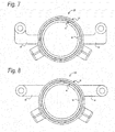
Fig. 7 is a view showing a first modification of cylinder attachment portions in the cylinder unit according to the present embodiment. -
Fig. 8 is a view showing a second modification of the cylinder attachment portions in the cylinder unit according to the present embodiment. -
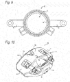
Fig. 9 is a view showing a third modification of the cylinder attachment portions in the cylinder unit according to the present embodiment. -
Fig. 10 is a view showing a first modification of the shape of a body according to the present embodiment. -
Fig. 11 is a view showing a second modification of the shape of the body according to the present embodiment. -
Fig. 12 is a view showing a configuration example of the cylinder unit in which opening surfaces of a bleeder hole and an inlet hole according to the present embodiment are disposed toward the inner side oblique outer circumference direction of the rotor. -
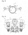
Fig. 13 is a view showing a configuration example of the cylinder unit in which the opening surfaces of a bleeder hole and an inlet hole according to the present embodiment are disposed toward the axial inner side of the rotor. -
Fig. 14 is a plan view showing a state in which a body having a center bridge is assembled to the cylinder unit shown inFig. 13 . -
Fig. 15 is a right side view showing an example of a disc brake device including a drive mechanism of a type other than hydraulic pressure. - Hereinafter, embodiments of the disc brake device of the present invention will be described in detail with reference to the drawings. In the drawings,
Fig. 1 is a front view showing a configuration of a disc brake device according to an embodiment of the present invention, andFig. 2 is a left side view.Fig. 3 is a view showing an A-A cross section inFig. 1 .Fig. 4 is a front view showing a configuration of a cylinder unit of the disc brake device according to the present embodiment.Fig. 5 is a partially exploded perspective view of the disc brake device according to the present embodiment, andFig. 6 is an exploded perspective view of the cylinder unit according to the present embodiment. - A
disc brake device 10 according to the present embodiment is based on abody 12, asupport 26 and acylinder unit 40, and each of them is configured separately. - The
body 12 is a floating member that plays a role of covering thesupport 26 and thecylinder unit 40, which will be described in detail, and pressing an outer side brake pad 20 (hereinafter simply referred to as outer pad 20) on a sliding surface of arotor 74 by sliding to the axis line direction of therotor 74. - As a specific configuration, the
disc brake device 10 includes aninner side body 14, anouter side body 18 and bridges (aside bridge 16 and amain bridge 16a). Theinner side body 14 is a part positioned on the side where thesupport 26 and thecylinder unit 40 are disposed with therotor 74 as a base when thebody 12 is assembled. Aguide hole 14b (refer toFig. 3 ) is provided on theinner side body 14 in addition to a pressure receiving portion 14a. The pressure receiving portion 14a is a part which is pressed from the inside by thesecond piston 50 disposed in thecylinder unit 40 which will be described in detail. Also, theguide hole 14b is a through hole for inserting aslide pin 54 for holding thebody 12 with respect to thesupport 26 which will be described in detail. - The
outer side body 18 is a part positioned on the opposite side of a disposition side of thesupport 26 with therotor 74 as a base when thebody 12 is assembled. In thedisc brake device 10 according to the present embodiment, theouter pad 20 is disposed on a surface facing therotor 74 in theouter body 18. - The
outer pad 20 is configured based on alining 22 which is a friction member and apressure plate 24 which is a steel plate with on which thelining 22 is stuck, and thepressure plate 24 is fastened to theouter side body 18. Apin receiving portion 18a supporting the tip of theslide pin 54 is provided on the side of theouter side body 18 facing therotor 74. - The bridge is a portion for connecting the
inner side body 14 to theouter side body 18 described above and is disposed so as to connect the two at the outer circumference side of therotor 74. In thebody 12 according to the present embodiment, the bridge disposed on the center side of thebody 12 is called amain bridge 16a, and the bridge disposed on the outside of thebody 12 is called aside bridge 16, so both the rigidity and weight reduction of thebody 12 are compatible. By providing the bridges (theside bridge 16 and themain bridge 16a), the pressing force received by theinner side body 14 is transmitted to theouter side body 18, and theouter pad 20 can be pressed to the sliding surface of therotor 74. - The
support 26 plays a role of assembling thedisc brake device 10 to a vehicle body (not shown). Thesupport 26 according to the present embodiment is configured based on abridge 28 andarm portions bridge 28 is a base member disposed toward the rotation-in side and the rotation-out side of therotor 74 and is provided with a fastening hole 28a for fixing thesupport 26 to the vehicle. - The
arm portions rotor 74 with both end portions of the rotation-in side and the rotation-out side of therotor 74 in thebridge 28 as base points. In the case of thearm portions positions Fig. 5 ) for fixing thecylinder unit 40, which will be described in detail, are provided at the tip of each arm portion. Through holes 30a1, 32a1 are formed for inserting the slide pins 54 used in the fixingpositions cylinder unit 40 is fixed. - An inner side brake pad (hereinafter simply referred to as an inner pad 34) is disposed between the pair of
arm portions outer pad 20, theinner pad 34 is basically made of a lining 36 which is a friction member and apressure plate 38 which is a steel plate. An abutment portion to thearm portion 32 is anear portion 38a provided on thepressure plate 38, and a pad clip for improving the slidability to the axial direction of therotor 74 is provided between theear portion 38a and thearm portions inner pad 34 disposed on thesupport 26 is pressed to the sliding surface of therotor 74 by being pressed to afirst piston 48 provided in thecylinder unit 40. - In the
support 26 according to the present embodiment, in thearm portions cylinder attachment portions 52 are fixed) 30a, 32a for fixing thecylinder unit 40 are positioned on the outer circumferential side in the radial direction of therotor 74 with respect to the torque receiving position (a position where theear portion 38a abuts) receiving the torque of theinner pad 34. - As shown in
Figs. 4 and6 in detail, thecylinder unit 40 has acylinder block 42 andcylinder attachment portions 52. Thecylinder block 42 has a penetratingly formed inner cylinder (a cylinder 44) and a bleeder hole/inlet hole 46 for supplying/discharging hydraulic oil from the outside of thecylinder block 42 to thecylinder 44. Thecylinder unit 40 is provided with afirst piston 48 and asecond piston 50. - The
first piston 48 is a piston for pressing theinner pad 34 and protrudes toward the disposition direction of therotor 74. Thesecond piston 50 is a piston protruding toward the opposite side of thefirst piston 48 and pressing the inner wall of theinner side body 14 of thebody 12. Therefore, when the hydraulic oil is supplied into thecylinder 44, thefirst piston 48 and thesecond piston 50 are pushed out to a relatively separate direction.Seals cylinder 44 and thefirst piston 48 and between thecylinder 44 and thesecond piston 50, respectively. - The
cylinder attachment portions 52 are support portions extending from the outer circumference of thecylinder block 42 to both directions of the rotation-in side and the rotation-out side of therotor 74 in an assembled state, and by fixing thecylinder attachment portions 52 to thesupport 26, the positioning of thecylinder block 42 is performed. - In the present embodiment, as shown in
Fig. 4 , thecylinder attachment portions 52 are extended in a substantially V-shape from thecylinder block 42. - As described above, in the
disc brake device 10 according to the present embodiment, the fixedpositions arm portions support arm 26 are provided at a position that is on the outer circumference side in the radial direction of therotor 74 with respect to the torque receiving positions of thearm portions 30, 32 (the positions where theear portion 38a of theinner pad 34 abuts). Therefore, thecylinder attachment portions 52 of thecylinder unit 40 are fixed to the fixedpositions cylinder unit 40 plays a role as a strength member. Therefore, when torque is applied to thearm portions arm portions rotor 74. - Therefore, even in a case where the
support 26 is configured by a light and thin member, thedisc brake device 10 can provide the strength necessary for braking. - Further, in the
disc brake device 10 according to the present embodiment, the fixedpositions rotor 74. A space is formed between twofixed positions cylinder attachment portions 52 in a V shape and fastening the tips thereof to the fixedpositions disc brake device 10 by disposing themain bridge 16a constituting thebody 12 in the space formed between the fixedpositions - The
body 12, thesupport 26, and thecylinder unit 40 having such a configuration are assembled via the slide pins 54. Asleeve 56 is disposed between thebody 12 and theslide pin 54, and a form held byboots sleeve 56 is adopted. Therefore, there is a little concern that the torque input to thebody 12 via theouter pad 20 places a load on theslide pin 54. Thecylinder unit 40 is assembled to thesupport 26 by screwing acap nut 62 formed in a pin shape to aslide pin 54 into which thesleeve 56, thecylinder attachment portion 52 and thesupport 26 are inserted, while positioning is performed by thesleeve 56. - The
pin 62a configured as the shape of thecap nut 62 is slidably engaged with thepin receiving portion 18a formed on theouter side body 18. As a result, when torque is input to thebody 12 via theouter pad 20, the torque is transmitted to thesupport 26 via thecap nut 62. Aclip 64 is disposed between thecap nut 62 and thepin receiving portion 18a in order to prevent an improvement in slidability and abrasion upon abutment. - in the
disc brake device 10 according to the present embodiment, ashim 66 is interposed on the abutment surface between thebody 12 and thesecond piston 50. Theshim 66 has ashim plate body 68, a clampingportion 70 and aclaw 72. - The
shim plate body 68 plays an original role of the shim, and even when the configuration members of thebody 12 and thesecond piston 50 have a difference in hardness, the surface pressure between thebody 12 and thesecond piston 50 can be improved. The clampingportion 70 is a part extending in a hook shape from theshim plate body 68 toward the side ofbody 12, and theshim 66 can be fixed by inserting theinner side body 14 between theshim plate body 68 and the clampingportion 70. Theclaws 72 are protrusions extending from theshim plate body 68 toward a plurality of sides of thesecond piston 50. It is configured that the outer circumference of thesecond piston 50 is clamped by a plurality ofclaws 72. - With such a configuration, the
body 12 can follow the movement of thesecond piston 50. Therefore, when the brake is opened, thebody 12 and thesecond piston 50 return simultaneously, so that it is possible to suppress drag of theouter pad 20 fastened to theouter side body 18. - In the
disc brake device 10 having such a configuration, since thesupport 26 and thecylinder unit 40 are formed separately, theinner pad 34 can be held by thesupport 26. As a result, in the floating typedisc brake device 10, the torque of theinner pad 34 is not received by the slide pins 54. - Further, since the
support 26 and thecylinder unit 40 are formed separately, it is possible to make configuration materials thereof different from each other, and it is possible to balance the weight reduction, rigidity, ease of processing, and cost. For example, it is possible to adopt such a structure in which thesupport 26 is configured by aluminum and thecylinder unit 40 is configured by iron. - In the
disc brake device 10 according to the present embodiment, the fixedpositions cylinder unit 40 are provided on the outer circumference side in the radial direction of therotor 74 with respect to the torque receiving position of thesupport 26, and thecylinder unit 40 is fixed by utilizing the fixedpositions cylinder unit 40 functions as a strength member of thesupport 26, and when the braking torque is received, it is possible to prevent thearm portions support 26 from spreading to the rotation-out side of therotor 74. - Further, the torque of the
outer pad 20 is transmitted to thesupport 26 via thecap nut 62 having a short pin length via thebody 12. Therefore, even on theouter pad 20 side, there is no necessity to worry about insufficient strength of thepin 62a (cap nut 62) receiving the torque. - Therefore, according to the disc brake device of the present embodiment, it is possible to reduce the load on the slide pins and to eliminate the concern about insufficient strength at the time of braking.
- Further, in the above embodiment, it is stated that the plurality of
claws 72 configuring theshim 66 clamp the outer circumference side of thesecond piston 50. However, the plurality ofclaws 72 may be configured to be fixed to thesecond piston 50 by pushing the inner circumference side of thesecond piston 50 mutually, so that thebody 12 and thesecond piston 50 are coupled to each other. - In the above embodiment, the
cylinder attachment portions 52 extending from thecylinder block 42 are described to be formed in a V shape with thecylinder block 42 as a base point. However, the form of thecylinder attachment portion 52 is not limited to this. That is, as long as thecylinder attachment portions 52 can be fixed to the fixedpositions rotor 74 with respect to the torque receiving position of thearm portions Figs. 7 to 9 may be used. - Specifically, in a case of the first modification of the
cylinder attachment portions 52 in thecylinder unit 40 shown inFig. 7 , thecylinder attachment portions 52 are formed on the outer circumference of thecylinder block 42 and extend perpendicular to a direction of the outer circumference side in the radial direction of therotor 74 after extending in the horizontal direction from the intersection point with a horizontal line passing through the center of thecylinder 44. Even in a case where thecylinder attachment portions 52 are formed in such a form, when thecylinder unit 40 is fixed to thesupport 26, the cylinder attachment portions 52 (the entire cylinder unit 40) work as strength members of thesupport 26, and the same effect as the above embodiment can be obtained. - in a second modification of the
cylinder attachment portions 52 in thecylinder unit 40 shown inFig. 8 , thecylinder attachment portions 52 extend horizontally from the upper half portion of thecylinder block 42. In such a form, when thecylinder unit 40 is assembled to thesupport 26, thecylinder attachment portions 52 and thecylinder block 42 are configured such that the fixedpositions arm portions - In a third modification of the
cylinder attachment portions 52 in thecylinder unit 40 shown inFig. 9 , the intersection point of the horizontal line passing through the center of thecylinder 44 and the outer circumference line of thecylinder block 42 is set as a base point, and thecylinder attachment portions 52 are extended in a horizontal direction. Even in such a configuration, thecylinder attachment portions 52 are fixed to the fixedpositions rotor 74 with respect to the torque receiving positions of thearm portions cylinder unit 40 can exert the function, the same effect as the above embodiment can be obtained. - Further, in the above embodiment, one large opening portion is formed between the two
main bridges 16a connecting theinner side body 14 and theouter side body 18 with regard to thebody 12. In such a configuration, in addition to the improvement of the heat dissipation, the weight of thebody 12 can be reduced. - On the other hand, when it is desired to increase the rigidity of the
body 12, it is possible to make a configuration as the first modification in the form of thebody 12 shown inFig. 10 for example. Specifically, a connectingportion 16b for connecting the twomain bridges 16a configuring the back portion of thebody 12 is provided therebetween. As a forming position of the connectingportion 16b, in the circumferential direction of therotor 74, the central portion between the twomain bridges 16a may be used as a base point. Further, in the axial direction of therotor 74, the central portion of the axial length of thebody 12 may be used as a base point. - In a case of such a configuration, the rigidity of the
body 12 can be increased compared with a form without the connectingportion 16b. In particular, when viewing thebody 12 in a plan view, it is possible to obtain a high strength against a force in an oblique direction where the connectingportion 16b is used as a base point. Further, by providing the opening portion between theouter side body 18 and the connectingportion 16b, it is also possible to confirm the worn state of the brake pads (theinner pad 34, the outer pad 20) from the outer circumference side of thebody 12. - Regarding the shape of the
body 12, it is also possible to adopt a form as the second modification in the form of thebody 12 shown inFig. 11 . Specifically, a center bridge 16c extending toward theinner side body 14 is provided with the connectingportion 16b in thebody 12 of the form shown inFig. 10 as a base point, and each opening portion is provided between the center bridge 16c and themain bridge 16a. Even in such a configuration, it is possible to provide an opening portion to confirm the worn state of the brake pads (theinner pad 34, the outer pad 20) between the connectingportion 16b and theouter side body 18. - Further, in such a configuration, the rigidity of the
body 12 can be increased compared with a form shown inFig. 10 . Usually, when thebody 12 is casted, pouring is performed from the upper side inFig. 11 , that is, theinner side body 14. In a case where the center bridge 16c is provided, the flowability can be kept good when hot water flows to theouter side body 18. Also, even after pouring, the wraparound becomes small when bubbles mixing in the hot water rise. Therefore, the deaeration property is also improved, and the concern that a cavity will be formed in the molded product after hardening is reduced. - Furthermore, since the opening portion between the center bridge 16c and the
main bridge 16a is formed without completely covering the space between the connectingportion 16b and theinner side body 14 with the center bridge 16c, the freedom of the layout on the structure in thecylinder unit 40 can be favorably maintained. Specifically, it is possible to protrude the bleeder hole/inlet hole 46 from each of the openings disposed on the rotation-in side and the rotation-out side of therotor 74 via the center bridge 16c. The inlet hole is a supply port for supplying the hydraulic oil to thecylinder 44 of thecylinder unit 40, and the bleeder hole is a discharge port for bleeding air from the hydraulic oil or exchanging the hydraulic oil. Further, since the opening portion formed between the center bridge 16c and themain bridge 16a is formed as a long hole whose major axis is the axial direction of therotor 74, even in a case where thelinings inner pad 34, the outer pad 20) wear, the bleeder hole/inlet hole 46 protruding from thecylinder block 42 does not interfere with thebody 12. - As shown in
Fig. 12 , since the bleeder hole/inlet hole 46 is disposed on the radial outer circumference side of therotor 74 in thecylinder block 42, the operation of bleeding air from the hydraulic oil and exchanging the hydraulic oil can be performed from the outer circumference side of thebody 12. This makes it possible to improve the operability when bleeding air from the hydraulic oil and exchanging the hydraulic oil compared with the case where the bleeder hole/inlet hole 46 is disposed inside thebody 12. - In this way, when the bleeder hole/
inlet hole 46 is disposed on the outer circumference side in the radial direction of therotor 74 in thecylinder block 42, if it is possible to access the bleeder hole/inlet hole 46 from the opening portion formed between the center bridge 16c and themain bridge 16a of thebody 12, there is no need to limit the disposition direction of the opening surface. For example, as can be read with reference toFigs. 11 and 12 , the opening surface of the bleeder hole/inlet hole 46 may be between the outer circumference side in the radial direction and the inner side in the axial direction of therotor 74, that is, toward the outer circumference direction oblique to the inner side, as shown inFigs. 13 and 14 , it may be disposed so that the opening surface faces the inner side in the axial direction of therotor 74.Fig. 13 is a view (back view) showing a configuration of a case where thecylinder unit 40 in which the bleeder hole/inlet hole 46 is disposed toward the inner side in the axial direction of therotor 74 is viewed from the inner side. Further,Fig. 14 is a plan view showing an example of a case where thebody 12 having the center bridge 16c is assembled to thecylinder unit 40 shown inFig. 13 . - Although not shown in the drawings, the bleeder hole/
inlet hole 46 may have its opening surface toward the outer circumference side in the radial direction of therotor 74. In either case, the same effect can be obtained in terms of improving operability when bleeding air from the hydraulic oil or exchanging the hydraulic oil. - In the
disc brake device 10 according to the above embodiment and the embodiment shown inFig. 10 , the bleeder hole/inlet hole 46 is shown to be disposed on the inner circumference side in the radial direction of therotor 74 in thecylinder block 42. However, naturally, for thedisc brake device 10 of the above embodiments and the form shown inFig. 10 , as shown inFig. 12 orFig. 13 , it is possible to apply one in which the bleeder hole/inlet hole 46 is arranged on the outer circumference side in the radial direction of therotor 74 in thecylinder block 42. - Further, in the above embodiments, the operation of the
first piston 48 and thesecond piston 50 is described to be achieved by supplying the hydraulic oil into thecylinder 44. However, the operation of thefirst piston 48 and thesecond piston 50 may be performed in a form other than hydraulic pressure. With such a configuration, it is possible to apply the disc brake device according to the present invention even in an environment where a hydraulic unit cannot be used because versatility can be improved. - A specific example of an operation mode other than hydraulic pressure can include a form in which a
motor gear unit 76 is used, as shown inFig. 15 . Themotor gear unit 76 is accompanied with thecylinder unit 40, and power is transmitted through a gear (not shown), whereby a booster mechanism (not shown) provided in thecylinder unit 40 operates. As a result, thefirst piston 48 and thesecond piston 50 protrude to a direction in which they relatively separate from each other, and generate a pressing force. - In the
disc brake device 10 according to the above embodiments, thecylinder unit 40 is fixed to thesupport 26 which is a fixing member. For this reason, the weight of thebody 12 can be reduced compared with a case where the motor is mounted on the body which is an operating portion, and as a motor, it is possible to adopt a small and light one with small output. Therefore, it is possible to reduce the weight of the entire disc brake device. - Further, in the above embodiments, the fixation of the
cylinder unit 40 to thesupport 26 is described as a configuration jointed with the slide pins 54 that hold thebody 12. However, if the fixedpositions rotor 74 with respect to the torque receiving positions in thearm portions cylinder unit 40 may be fixed to thesupport 26 by a fixing mechanism different from the slide pins 54. - Here, the characteristics of embodiments of the disc brake device according to the present invention described above are briefly summarized and listed below.
- [1] Afloating type disc brake device (10) in which a body (12), a support (26), and a cylinder unit (40) are configured separately, and a first piston (40) and a second piston (50) are accommodated in the cylinder unit, wherein
the cylinder unit is fixed to arm portions (30, 32) provided on both the rotation-in side and the rotation-out side of a rotor (74) in the support via cylinder attachment portions (52) disposed on the outer circumference side of the cylinder unit. - [2] The disc brake device described in (1) above, wherein
a fixed position for fixing the cylinder unit in the arm portion is positioned on the outer circumference side in the radial direction of the rotor with respect to a torque receiving position in the arm portion. - [3] The disc brake device described in (1) or (2) above, wherein
the fixed position for fixing the cylinder unit in the arm portion is positioned on the outer circumference side in the radial direction with respect to the outer circumference of the rotor. - [4] The disc brake device described in any one of (1) to (3) above, wherein
the cylinder attachment portion is fixed to the fixed position for fixing the cylinder unit via a slide pin (54) holding the body. - [5] The disc brake device described in any one of (1) to (4) above, wherein
the disposing position of the cylinder unit is positioned on the inner circumference side in the radial direction with respect to the fixed position for fixing the cylinder unit, and a space is provided between the two fixed positions positioning on the rotation-in side and rotation-out side of the rotor, and
main bridges (16a) connecting the inner side and outer side of the body are provided in the body at the rotation-in side and rotation-out side of the rotor respectively in the space provided between the fixed positions. - [6] The disc brake device described in (5) above, wherein
a connecting portion for connecting the two main bridges is provided in a center part of the body back portion in an axial direction of the rotor and between the main bridge disposed on the rotation-in side and the main bridge disposed on the rotation-out side. - [7] The disc brake device described in (6) above, wherein
a center bridge (16c) extending from the connecting portion to the inner side of the body is provided. - [8] The disc brake device described in any one of (1) to (7) above, wherein
the support and the cylinder unit are made of different materials. - [9] The disc brake device described in any one of (1) to (8) above, wherein
the first piston and the second piston are configured to generate pressing force by power other than hydraulic pressure. - The present invention is not limited to the above-described embodiments, and can be appropriately modified, improved and the like. In addition, materials, shapes, dimensions, numbers, disposition locations, and the like of configuration elements in the above-described embodiments are arbitrary as far as the present invention can be achieved, and are not limited.
- This application is based on a Japanese patent application (Japanese Patent Application No.
2015-137810) filed on July 9, 2015 2016-022346) filed on February 9, 2016 - According to the disc brake device of the present invention, it is possible to provide a floating type disc brake device capable of reducing the load on slide pins and eliminating the concern about insufficient strength at the time of braking.
-
- 10
- disc brake device
- 12
- body
- 14
- inner side body
- 14a
- pressure receiving portion
- 14b
- guide hole
- 16
- side bridge
- 16a
- main bridge
- 16b
- connecting portion
- 16c
- center bridge
- 18
- outer side body
- 18a
- pin receiving portion
- 20
- outer pad
- 22
- lining
- 24
- pressure plate
- 26
- support
- 28
- bridge
- 28a
- fastening hole
- 30
- arm portion
- 30a
- fixed position
- 30a1
- through hole
- 32
- arm portion
- 32a
- fixed position
- 32a1
- through hole
- 34
- inner pad
- 36
- lining
- 38
- pressure plate
- 38a
- ear portion
- 40
- cylinder unit
- 42
- cylinder block
- 44
- cylinder
- 46
- bleeder hole/inlet hole
- 48
- first piston
- 50
- second piston
- 52
- cylinder attachment portion
- 54
- slide pin
- 56
- sleeve
- 58
- boots
- 60
- boots
- 62
- cap nut
- 62a
- pin
- 64
- clip
- 66
- shim
- 68
- shim plate body
- 70
- clamping portion
- 72
- claw
- 74
- rotor
Claims (9)
- A floating type disc brake device in which a body, a support and a cylinder unit are configured separately, and a first piston and a second piston are accommodated in the cylinder unit, wherein
the cylinder unit is fixed to arm portions provided on both a rotation-in side and a rotation-out side of a rotor in the support via cylinder attachment portions disposed on an outer circumference side of the cylinder unit. - The disc brake device described in claim 1, wherein
a fixed position for fixing the cylinder unit in the arm portion is positioned on a outer circumference side in a radial direction of the rotor with respect to a torque receiving position in the arm portion. - The disc brake device described in claim 1 or 2, wherein
the fixed position for fixing the cylinder unit in the arm portion is positioned on the outer circumference side in the radial direction with respect to an outer circumference of the rotor. - The disc brake device described in any one of claims 1 to 3, wherein
the cylinder attachment portion is fixed to the fixed position for fixing the cylinder unit via a slide pin holding the body. - The disc brake device described in any one of claims 1 to 4 above, wherein
a disposing position of the cylinder unit is positioned on an inner circumference side in the radial direction with respect to the fixed position for fixing the cylinder unit, and a space is provided between the two fixed positions positioning on the rotation-in side and rotation-out side of the rotor, and
main bridges connecting the inner side and outer side of the body are provided in the body at the rotation-in side and rotation-out side of the rotor respectively in the space provided between the fixed positions. - The disc brake device described in claim 5, wherein
a connecting portion for connecting the two main bridges is provided in a center part of the body back portion in an axial direction of the rotor and between the main bridge disposed on the rotation-in side and the main bridge disposed on the rotation-out side. - The disc brake device described in claim 6, wherein
a center bridge extending from the connecting portion to an inner side of the body is provided. - The disc brake device described in any one of claims 1 to 7, wherein
the support and the cylinder unit are made of different materials. - The disc brake device described in any one of claims 1 to 8, wherein
the first piston and the second piston are configured to generate pressing force by power other than hydraulic pressure.
Applications Claiming Priority (3)
| Application Number | Priority Date | Filing Date | Title |
|---|---|---|---|
| JP2015137810 | 2015-07-09 | ||
| JP2016022346A JP6680554B2 (en) | 2015-07-09 | 2016-02-09 | Disc brake device |
| PCT/JP2016/069088 WO2017006803A1 (en) | 2015-07-09 | 2016-06-28 | Disc brake device |
Publications (3)
| Publication Number | Publication Date |
|---|---|
| EP3321535A1 true EP3321535A1 (en) | 2018-05-16 |
| EP3321535A4 EP3321535A4 (en) | 2019-03-27 |
| EP3321535B1 EP3321535B1 (en) | 2020-01-08 |
Family
ID=57889446
Family Applications (1)
| Application Number | Title | Priority Date | Filing Date |
|---|---|---|---|
| EP16821272.8A Active EP3321535B1 (en) | 2015-07-09 | 2016-06-28 | Disc brake device |
Country Status (4)
| Country | Link |
|---|---|
| US (1) | US10670092B2 (en) |
| EP (1) | EP3321535B1 (en) |
| JP (1) | JP6680554B2 (en) |
| CN (1) | CN107850143B (en) |
Families Citing this family (6)
| Publication number | Priority date | Publication date | Assignee | Title |
|---|---|---|---|---|
| EP3499072A1 (en) * | 2017-12-15 | 2019-06-19 | Meritor Heavy Vehicle Braking Systems (UK) Limited | Brake caliper |
| JP7192572B2 (en) | 2019-02-28 | 2022-12-20 | トヨタ自動車株式会社 | disc brake |
| JP7120133B2 (en) | 2019-04-10 | 2022-08-17 | トヨタ自動車株式会社 | disc brake |
| CN112413006B (en) * | 2019-08-23 | 2022-02-08 | 比亚迪股份有限公司 | Disc brake and vehicle |
| JP7444095B2 (en) * | 2021-02-09 | 2024-03-06 | トヨタ自動車株式会社 | disc brake |
| WO2025083608A1 (en) | 2023-10-18 | 2025-04-24 | Akebono Brake Industry Co., Ltd. | Integrated lock mechanism and controls for park brake actuation |
Family Cites Families (31)
| Publication number | Priority date | Publication date | Assignee | Title |
|---|---|---|---|---|
| US1297437A (en) * | 1915-11-23 | 1919-03-18 | Charles O Birney | Straight-air one-man equipment. |
| US3245500A (en) * | 1963-02-12 | 1966-04-12 | Girling Ltd | Spot type disc brakes |
| GB1148524A (en) | 1965-05-06 | 1969-04-16 | Girling Ltd | Improvements in disc brakes |
| GB1107209A (en) | 1965-11-20 | 1968-03-27 | Girling Holdings Ltd | Improvements in disc brakes |
| US3656589A (en) * | 1969-05-10 | 1972-04-18 | Aisin Seiki | Spot type disc brakes |
| US3912051A (en) * | 1969-10-08 | 1975-10-14 | Aisin Seiki | Spot type disc brake |
| US3651898A (en) | 1969-10-24 | 1972-03-28 | Girling Ltd | Disc brake caliper structure |
| US3773149A (en) * | 1971-05-10 | 1973-11-20 | Nissan Motor | Automotive disc brake |
| US3897858A (en) * | 1971-10-20 | 1975-08-05 | Nissan Motor | Closed loop type disc brake |
| BE790377A (en) * | 1971-10-20 | 1973-02-15 | Nissan Motor | DISC BRAKE |
| IT1005453B (en) * | 1973-02-21 | 1976-08-20 | Ferodo Sa | DISC BRAKE ESPECIALLY FOR AUTOMOBILE VEHICLES |
| GB1428026A (en) * | 1973-04-05 | 1976-03-17 | Girling Ltd | Sliding caliper disc brakes |
| JPS5324638Y2 (en) * | 1973-12-28 | 1978-06-23 | ||
| GB1567602A (en) * | 1975-11-07 | 1980-05-21 | Girling Ltd | Hydraulicallyoperated disc brakes for vehicles |
| JPS5274776A (en) * | 1975-12-19 | 1977-06-23 | Nissan Motor Co Ltd | Disc brake |
| GB1541021A (en) * | 1976-09-22 | 1979-02-21 | Girling Ltd | Disc brakes for vehicles |
| IN150357B (en) * | 1979-01-18 | 1982-09-18 | Lucas Industries Ltd | |
| JPS6184425A (en) | 1984-09-29 | 1986-04-30 | Nissin Kogyo Kk | Disc brake |
| DE3919179A1 (en) | 1989-06-12 | 1990-12-13 | Lucas Ind Plc | PARTIAL DISC BRAKE WITH SWIMMING CALIPER AND PRESSURE PLATE |
| GB9100944D0 (en) | 1991-01-16 | 1991-02-27 | Lucas Ind Plc | Brake actuator |
| JPH08254234A (en) * | 1995-03-20 | 1996-10-01 | Nissin Kogyo Kk | Disc brakes for vehicles |
| EP1287269B1 (en) * | 2000-06-07 | 2007-04-04 | Lucas Automotive Gmbh | Floating caliper for a disk brake, and disk brake |
| US6695099B1 (en) * | 2003-01-15 | 2004-02-24 | Delphi Technologies, Inc. | Twin piston single bore brake caliper apparatus |
| JP2006231954A (en) * | 2005-02-22 | 2006-09-07 | Honda Motor Co Ltd | Electric brake device |
| JP2007321975A (en) * | 2006-05-02 | 2007-12-13 | Akebono Brake Ind Co Ltd | Caliper for disc brake |
| GB2439332A (en) | 2006-06-22 | 2007-12-27 | Automotive Products Italia | A floating calliper disc brake |
| JP2009058035A (en) * | 2007-08-31 | 2009-03-19 | Advics:Kk | Movable caliper type disk brake device |
| US8485323B2 (en) * | 2010-10-08 | 2013-07-16 | Akebono Brake Corporation | Caliper assembly for disc brake system |
| JP6202434B2 (en) * | 2012-10-26 | 2017-09-27 | 曙ブレーキ工業株式会社 | Disc brake device |
| CN104755786B (en) * | 2012-10-26 | 2017-03-15 | 曙制动器工业株式会社 | Disc brake assembly and the braking backing plate for disc brake assembly |
| JP5980670B2 (en) * | 2012-12-03 | 2016-08-31 | 曙ブレーキ工業株式会社 | Caliper for disc brake |
-
2016
- 2016-02-09 JP JP2016022346A patent/JP6680554B2/en active Active
- 2016-06-28 EP EP16821272.8A patent/EP3321535B1/en active Active
- 2016-06-28 CN CN201680040608.4A patent/CN107850143B/en active Active
- 2016-06-28 US US15/741,775 patent/US10670092B2/en active Active
Also Published As
| Publication number | Publication date |
|---|---|
| JP6680554B2 (en) | 2020-04-15 |
| US20180195564A1 (en) | 2018-07-12 |
| EP3321535A4 (en) | 2019-03-27 |
| CN107850143A (en) | 2018-03-27 |
| CN107850143B (en) | 2020-07-31 |
| US10670092B2 (en) | 2020-06-02 |
| JP2017020644A (en) | 2017-01-26 |
| EP3321535B1 (en) | 2020-01-08 |
Similar Documents
| Publication | Publication Date | Title |
|---|---|---|
| EP3321535B1 (en) | Disc brake device | |
| JP6446275B2 (en) | Counter-piston disc brake caliper | |
| EP2392835A2 (en) | Disc brake | |
| JP2006057718A (en) | Floating calliper type disk brake | |
| US12066066B2 (en) | Vehicular disc brake | |
| EP3222871A1 (en) | Disc brake device | |
| JP2015124812A (en) | Disc brake device | |
| WO2015137359A1 (en) | Floating-type disc brake | |
| JP6202434B2 (en) | Disc brake device | |
| CN108700143B (en) | Partially lined motor vehicle disc brake | |
| US10907695B2 (en) | Brake caliper of a disc brake | |
| WO2017130628A1 (en) | Disc brake device and brake pad for disc brake device | |
| US20060289249A1 (en) | Sliding cylinder bore caliper assembly | |
| WO2016006581A1 (en) | Disc brake device | |
| WO2017006803A1 (en) | Disc brake device | |
| US10451127B2 (en) | Utility vehicle disk brake | |
| JP4718422B2 (en) | Disc brake | |
| JP4387852B2 (en) | Vehicle disc brake | |
| JP4288197B2 (en) | Vehicle disc brake | |
| JP2000186730A (en) | Integrated full frame structure floating disc brake | |
| CN104246271B (en) | Disk brake | |
| CN111197630B (en) | Brake assembly | |
| JP5634952B2 (en) | Vehicle disc brake | |
| CN207261517U (en) | Brake caliper and vehicle | |
| JPH1182580A (en) | Disc brakes for vehicles |
Legal Events
| Date | Code | Title | Description |
|---|---|---|---|
| STAA | Information on the status of an ep patent application or granted ep patent |
Free format text: STATUS: THE INTERNATIONAL PUBLICATION HAS BEEN MADE |
|
| PUAI | Public reference made under article 153(3) epc to a published international application that has entered the european phase |
Free format text: ORIGINAL CODE: 0009012 |
|
| STAA | Information on the status of an ep patent application or granted ep patent |
Free format text: STATUS: REQUEST FOR EXAMINATION WAS MADE |
|
| 17P | Request for examination filed |
Effective date: 20180108 |
|
| AK | Designated contracting states |
Kind code of ref document: A1 Designated state(s): AL AT BE BG CH CY CZ DE DK EE ES FI FR GB GR HR HU IE IS IT LI LT LU LV MC MK MT NL NO PL PT RO RS SE SI SK SM TR |
|
| AX | Request for extension of the european patent |
Extension state: BA ME |
|
| DAV | Request for validation of the european patent (deleted) | ||
| DAX | Request for extension of the european patent (deleted) | ||
| A4 | Supplementary search report drawn up and despatched |
Effective date: 20190226 |
|
| RIC1 | Information provided on ipc code assigned before grant |
Ipc: F16D 65/00 20060101ALI20190220BHEP Ipc: F16D 55/227 20060101ALI20190220BHEP Ipc: F16D 125/04 20120101ALI20190220BHEP Ipc: F16D 121/24 20120101ALI20190220BHEP Ipc: F16D 55/226 20060101AFI20190220BHEP Ipc: F16D 125/06 20120101ALI20190220BHEP Ipc: B60T 13/74 20060101ALI20190220BHEP Ipc: F16D 121/04 20120101ALI20190220BHEP Ipc: F16D 65/18 20060101ALI20190220BHEP |
|
| GRAP | Despatch of communication of intention to grant a patent |
Free format text: ORIGINAL CODE: EPIDOSNIGR1 |
|
| STAA | Information on the status of an ep patent application or granted ep patent |
Free format text: STATUS: GRANT OF PATENT IS INTENDED |
|
| RIC1 | Information provided on ipc code assigned before grant |
Ipc: F16D 55/226 20060101AFI20190709BHEP Ipc: F16D 121/24 20120101ALI20190709BHEP Ipc: F16D 65/00 20060101ALI20190709BHEP Ipc: F16D 65/18 20060101ALI20190709BHEP Ipc: F16D 121/04 20120101ALI20190709BHEP Ipc: F16D 125/06 20120101ALI20190709BHEP Ipc: F16D 125/04 20120101ALI20190709BHEP Ipc: B60T 13/74 20060101ALI20190709BHEP Ipc: F16D 55/227 20060101ALI20190709BHEP |
|
| INTG | Intention to grant announced |
Effective date: 20190812 |
|
| GRAS | Grant fee paid |
Free format text: ORIGINAL CODE: EPIDOSNIGR3 |
|
| GRAA | (expected) grant |
Free format text: ORIGINAL CODE: 0009210 |
|
| STAA | Information on the status of an ep patent application or granted ep patent |
Free format text: STATUS: THE PATENT HAS BEEN GRANTED |
|
| AK | Designated contracting states |
Kind code of ref document: B1 Designated state(s): AL AT BE BG CH CY CZ DE DK EE ES FI FR GB GR HR HU IE IS IT LI LT LU LV MC MK MT NL NO PL PT RO RS SE SI SK SM TR |
|
| REG | Reference to a national code |
Ref country code: GB Ref legal event code: FG4D |
|
| REG | Reference to a national code |
Ref country code: CH Ref legal event code: EP |
|
| REG | Reference to a national code |
Ref country code: DE Ref legal event code: R096 Ref document number: 602016028053 Country of ref document: DE |
|
| REG | Reference to a national code |
Ref country code: IE Ref legal event code: FG4D |
|
| REG | Reference to a national code |
Ref country code: AT Ref legal event code: REF Ref document number: 1223094 Country of ref document: AT Kind code of ref document: T Effective date: 20200215 |
|
| REG | Reference to a national code |
Ref country code: NL Ref legal event code: MP Effective date: 20200108 |
|
| REG | Reference to a national code |
Ref country code: LT Ref legal event code: MG4D |
|
| PG25 | Lapsed in a contracting state [announced via postgrant information from national office to epo] |
Ref country code: PT Free format text: LAPSE BECAUSE OF FAILURE TO SUBMIT A TRANSLATION OF THE DESCRIPTION OR TO PAY THE FEE WITHIN THE PRESCRIBED TIME-LIMIT Effective date: 20200531 Ref country code: NL Free format text: LAPSE BECAUSE OF FAILURE TO SUBMIT A TRANSLATION OF THE DESCRIPTION OR TO PAY THE FEE WITHIN THE PRESCRIBED TIME-LIMIT Effective date: 20200108 Ref country code: LT Free format text: LAPSE BECAUSE OF FAILURE TO SUBMIT A TRANSLATION OF THE DESCRIPTION OR TO PAY THE FEE WITHIN THE PRESCRIBED TIME-LIMIT Effective date: 20200108 Ref country code: NO Free format text: LAPSE BECAUSE OF FAILURE TO SUBMIT A TRANSLATION OF THE DESCRIPTION OR TO PAY THE FEE WITHIN THE PRESCRIBED TIME-LIMIT Effective date: 20200408 Ref country code: FI Free format text: LAPSE BECAUSE OF FAILURE TO SUBMIT A TRANSLATION OF THE DESCRIPTION OR TO PAY THE FEE WITHIN THE PRESCRIBED TIME-LIMIT Effective date: 20200108 Ref country code: RS Free format text: LAPSE BECAUSE OF FAILURE TO SUBMIT A TRANSLATION OF THE DESCRIPTION OR TO PAY THE FEE WITHIN THE PRESCRIBED TIME-LIMIT Effective date: 20200108 |
|
| PG25 | Lapsed in a contracting state [announced via postgrant information from national office to epo] |
Ref country code: HR Free format text: LAPSE BECAUSE OF FAILURE TO SUBMIT A TRANSLATION OF THE DESCRIPTION OR TO PAY THE FEE WITHIN THE PRESCRIBED TIME-LIMIT Effective date: 20200108 Ref country code: GR Free format text: LAPSE BECAUSE OF FAILURE TO SUBMIT A TRANSLATION OF THE DESCRIPTION OR TO PAY THE FEE WITHIN THE PRESCRIBED TIME-LIMIT Effective date: 20200409 Ref country code: LV Free format text: LAPSE BECAUSE OF FAILURE TO SUBMIT A TRANSLATION OF THE DESCRIPTION OR TO PAY THE FEE WITHIN THE PRESCRIBED TIME-LIMIT Effective date: 20200108 Ref country code: BG Free format text: LAPSE BECAUSE OF FAILURE TO SUBMIT A TRANSLATION OF THE DESCRIPTION OR TO PAY THE FEE WITHIN THE PRESCRIBED TIME-LIMIT Effective date: 20200408 Ref country code: IS Free format text: LAPSE BECAUSE OF FAILURE TO SUBMIT A TRANSLATION OF THE DESCRIPTION OR TO PAY THE FEE WITHIN THE PRESCRIBED TIME-LIMIT Effective date: 20200508 Ref country code: SE Free format text: LAPSE BECAUSE OF FAILURE TO SUBMIT A TRANSLATION OF THE DESCRIPTION OR TO PAY THE FEE WITHIN THE PRESCRIBED TIME-LIMIT Effective date: 20200108 |
|
| REG | Reference to a national code |
Ref country code: DE Ref legal event code: R097 Ref document number: 602016028053 Country of ref document: DE |
|
| PG25 | Lapsed in a contracting state [announced via postgrant information from national office to epo] |
Ref country code: EE Free format text: LAPSE BECAUSE OF FAILURE TO SUBMIT A TRANSLATION OF THE DESCRIPTION OR TO PAY THE FEE WITHIN THE PRESCRIBED TIME-LIMIT Effective date: 20200108 Ref country code: SM Free format text: LAPSE BECAUSE OF FAILURE TO SUBMIT A TRANSLATION OF THE DESCRIPTION OR TO PAY THE FEE WITHIN THE PRESCRIBED TIME-LIMIT Effective date: 20200108 Ref country code: DK Free format text: LAPSE BECAUSE OF FAILURE TO SUBMIT A TRANSLATION OF THE DESCRIPTION OR TO PAY THE FEE WITHIN THE PRESCRIBED TIME-LIMIT Effective date: 20200108 Ref country code: RO Free format text: LAPSE BECAUSE OF FAILURE TO SUBMIT A TRANSLATION OF THE DESCRIPTION OR TO PAY THE FEE WITHIN THE PRESCRIBED TIME-LIMIT Effective date: 20200108 Ref country code: CZ Free format text: LAPSE BECAUSE OF FAILURE TO SUBMIT A TRANSLATION OF THE DESCRIPTION OR TO PAY THE FEE WITHIN THE PRESCRIBED TIME-LIMIT Effective date: 20200108 Ref country code: ES Free format text: LAPSE BECAUSE OF FAILURE TO SUBMIT A TRANSLATION OF THE DESCRIPTION OR TO PAY THE FEE WITHIN THE PRESCRIBED TIME-LIMIT Effective date: 20200108 Ref country code: SK Free format text: LAPSE BECAUSE OF FAILURE TO SUBMIT A TRANSLATION OF THE DESCRIPTION OR TO PAY THE FEE WITHIN THE PRESCRIBED TIME-LIMIT Effective date: 20200108 |
|
| PLBE | No opposition filed within time limit |
Free format text: ORIGINAL CODE: 0009261 |
|
| STAA | Information on the status of an ep patent application or granted ep patent |
Free format text: STATUS: NO OPPOSITION FILED WITHIN TIME LIMIT |
|
| REG | Reference to a national code |
Ref country code: AT Ref legal event code: MK05 Ref document number: 1223094 Country of ref document: AT Kind code of ref document: T Effective date: 20200108 |
|
| 26N | No opposition filed |
Effective date: 20201009 |
|
| PG25 | Lapsed in a contracting state [announced via postgrant information from national office to epo] |
Ref country code: IT Free format text: LAPSE BECAUSE OF FAILURE TO SUBMIT A TRANSLATION OF THE DESCRIPTION OR TO PAY THE FEE WITHIN THE PRESCRIBED TIME-LIMIT Effective date: 20200108 Ref country code: AT Free format text: LAPSE BECAUSE OF FAILURE TO SUBMIT A TRANSLATION OF THE DESCRIPTION OR TO PAY THE FEE WITHIN THE PRESCRIBED TIME-LIMIT Effective date: 20200108 Ref country code: MC Free format text: LAPSE BECAUSE OF FAILURE TO SUBMIT A TRANSLATION OF THE DESCRIPTION OR TO PAY THE FEE WITHIN THE PRESCRIBED TIME-LIMIT Effective date: 20200108 |
|
| REG | Reference to a national code |
Ref country code: CH Ref legal event code: PL |
|
| PG25 | Lapsed in a contracting state [announced via postgrant information from national office to epo] |
Ref country code: PL Free format text: LAPSE BECAUSE OF FAILURE TO SUBMIT A TRANSLATION OF THE DESCRIPTION OR TO PAY THE FEE WITHIN THE PRESCRIBED TIME-LIMIT Effective date: 20200108 Ref country code: SI Free format text: LAPSE BECAUSE OF FAILURE TO SUBMIT A TRANSLATION OF THE DESCRIPTION OR TO PAY THE FEE WITHIN THE PRESCRIBED TIME-LIMIT Effective date: 20200108 |
|
| GBPC | Gb: european patent ceased through non-payment of renewal fee |
Effective date: 20200628 |
|
| PG25 | Lapsed in a contracting state [announced via postgrant information from national office to epo] |
Ref country code: LU Free format text: LAPSE BECAUSE OF NON-PAYMENT OF DUE FEES Effective date: 20200628 |
|
| REG | Reference to a national code |
Ref country code: BE Ref legal event code: MM Effective date: 20200630 |
|
| PG25 | Lapsed in a contracting state [announced via postgrant information from national office to epo] |
Ref country code: GB Free format text: LAPSE BECAUSE OF NON-PAYMENT OF DUE FEES Effective date: 20200628 Ref country code: IE Free format text: LAPSE BECAUSE OF NON-PAYMENT OF DUE FEES Effective date: 20200628 Ref country code: FR Free format text: LAPSE BECAUSE OF NON-PAYMENT OF DUE FEES Effective date: 20200630 Ref country code: LI Free format text: LAPSE BECAUSE OF NON-PAYMENT OF DUE FEES Effective date: 20200630 Ref country code: CH Free format text: LAPSE BECAUSE OF NON-PAYMENT OF DUE FEES Effective date: 20200630 |
|
| PG25 | Lapsed in a contracting state [announced via postgrant information from national office to epo] |
Ref country code: BE Free format text: LAPSE BECAUSE OF NON-PAYMENT OF DUE FEES Effective date: 20200630 |
|
| PG25 | Lapsed in a contracting state [announced via postgrant information from national office to epo] |
Ref country code: TR Free format text: LAPSE BECAUSE OF FAILURE TO SUBMIT A TRANSLATION OF THE DESCRIPTION OR TO PAY THE FEE WITHIN THE PRESCRIBED TIME-LIMIT Effective date: 20200108 Ref country code: MT Free format text: LAPSE BECAUSE OF FAILURE TO SUBMIT A TRANSLATION OF THE DESCRIPTION OR TO PAY THE FEE WITHIN THE PRESCRIBED TIME-LIMIT Effective date: 20200108 Ref country code: CY Free format text: LAPSE BECAUSE OF FAILURE TO SUBMIT A TRANSLATION OF THE DESCRIPTION OR TO PAY THE FEE WITHIN THE PRESCRIBED TIME-LIMIT Effective date: 20200108 |
|
| PG25 | Lapsed in a contracting state [announced via postgrant information from national office to epo] |
Ref country code: MK Free format text: LAPSE BECAUSE OF FAILURE TO SUBMIT A TRANSLATION OF THE DESCRIPTION OR TO PAY THE FEE WITHIN THE PRESCRIBED TIME-LIMIT Effective date: 20200108 Ref country code: AL Free format text: LAPSE BECAUSE OF FAILURE TO SUBMIT A TRANSLATION OF THE DESCRIPTION OR TO PAY THE FEE WITHIN THE PRESCRIBED TIME-LIMIT Effective date: 20200108 |
|
| P01 | Opt-out of the competence of the unified patent court (upc) registered |
Effective date: 20230512 |
|
| PGFP | Annual fee paid to national office [announced via postgrant information from national office to epo] |
Ref country code: DE Payment date: 20250507 Year of fee payment: 10 |