EP3321523B1 - Fasteners having enhanced electrical energy dispersion properties - Google Patents
Fasteners having enhanced electrical energy dispersion properties Download PDFInfo
- Publication number
- EP3321523B1 EP3321523B1 EP17199481.7A EP17199481A EP3321523B1 EP 3321523 B1 EP3321523 B1 EP 3321523B1 EP 17199481 A EP17199481 A EP 17199481A EP 3321523 B1 EP3321523 B1 EP 3321523B1
- Authority
- EP
- European Patent Office
- Prior art keywords
- coating
- shank
- fastener
- lubricant
- irregular
- Prior art date
- Legal status (The legal status is an assumption and is not a legal conclusion. Google has not performed a legal analysis and makes no representation as to the accuracy of the status listed.)
- Active
Links
- 239000006185 dispersion Substances 0.000 title description 3
- 238000000576 coating method Methods 0.000 claims description 202
- 239000011248 coating agent Substances 0.000 claims description 198
- 239000000314 lubricant Substances 0.000 claims description 50
- 238000000034 method Methods 0.000 claims description 44
- 230000001788 irregular Effects 0.000 claims description 37
- 238000009434 installation Methods 0.000 claims description 30
- 229910052751 metal Inorganic materials 0.000 claims description 30
- 239000002184 metal Substances 0.000 claims description 30
- BXWNKGSJHAJOGX-UHFFFAOYSA-N hexadecan-1-ol Chemical compound CCCCCCCCCCCCCCCCO BXWNKGSJHAJOGX-UHFFFAOYSA-N 0.000 claims description 14
- 238000013461 design Methods 0.000 claims description 11
- 238000005507 spraying Methods 0.000 claims description 10
- 239000000049 pigment Substances 0.000 claims description 9
- 229960000541 cetyl alcohol Drugs 0.000 claims description 7
- RTAQQCXQSZGOHL-UHFFFAOYSA-N Titanium Chemical compound [Ti] RTAQQCXQSZGOHL-UHFFFAOYSA-N 0.000 claims description 6
- 239000007921 spray Substances 0.000 claims description 6
- 239000010936 titanium Substances 0.000 claims description 6
- 229910052719 titanium Inorganic materials 0.000 claims description 6
- 229910052802 copper Inorganic materials 0.000 claims description 5
- 239000000463 material Substances 0.000 claims description 5
- CWQXQMHSOZUFJS-UHFFFAOYSA-N molybdenum disulfide Chemical compound S=[Mo]=S CWQXQMHSOZUFJS-UHFFFAOYSA-N 0.000 claims description 5
- 229910052982 molybdenum disulfide Inorganic materials 0.000 claims description 5
- CWYNVVGOOAEACU-UHFFFAOYSA-N Fe2+ Chemical compound [Fe+2] CWYNVVGOOAEACU-UHFFFAOYSA-N 0.000 claims description 4
- 229910045601 alloy Inorganic materials 0.000 claims description 4
- 239000000956 alloy Substances 0.000 claims description 4
- 229910000990 Ni alloy Inorganic materials 0.000 claims description 3
- 238000007743 anodising Methods 0.000 claims 1
- 238000004519 manufacturing process Methods 0.000 description 18
- 239000002131 composite material Substances 0.000 description 15
- 238000003780 insertion Methods 0.000 description 12
- 230000037431 insertion Effects 0.000 description 12
- 241001136800 Anas acuta Species 0.000 description 6
- 238000010586 diagram Methods 0.000 description 6
- 230000007704 transition Effects 0.000 description 6
- 230000008901 benefit Effects 0.000 description 4
- 238000012423 maintenance Methods 0.000 description 4
- 230000008569 process Effects 0.000 description 4
- 239000007787 solid Substances 0.000 description 4
- 238000003860 storage Methods 0.000 description 4
- 230000007613 environmental effect Effects 0.000 description 3
- 230000006870 function Effects 0.000 description 3
- 230000010354 integration Effects 0.000 description 3
- 230000000873 masking effect Effects 0.000 description 3
- 230000004323 axial length Effects 0.000 description 2
- 230000009286 beneficial effect Effects 0.000 description 2
- 230000007797 corrosion Effects 0.000 description 2
- 238000005260 corrosion Methods 0.000 description 2
- 238000005553 drilling Methods 0.000 description 2
- 238000009413 insulation Methods 0.000 description 2
- 230000000670 limiting effect Effects 0.000 description 2
- 230000001050 lubricating effect Effects 0.000 description 2
- 238000003754 machining Methods 0.000 description 2
- 230000015654 memory Effects 0.000 description 2
- 230000021715 photosynthesis, light harvesting Effects 0.000 description 2
- 230000019612 pigmentation Effects 0.000 description 2
- 229920000049 Carbon (fiber) Polymers 0.000 description 1
- 230000009471 action Effects 0.000 description 1
- 238000010923 batch production Methods 0.000 description 1
- 238000005422 blasting Methods 0.000 description 1
- 239000004917 carbon fiber Substances 0.000 description 1
- 230000008859 change Effects 0.000 description 1
- 230000000295 complement effect Effects 0.000 description 1
- 238000013500 data storage Methods 0.000 description 1
- 230000003247 decreasing effect Effects 0.000 description 1
- 230000001627 detrimental effect Effects 0.000 description 1
- 230000003292 diminished effect Effects 0.000 description 1
- 238000007598 dipping method Methods 0.000 description 1
- 238000009826 distribution Methods 0.000 description 1
- 239000012636 effector Substances 0.000 description 1
- 239000002828 fuel tank Substances 0.000 description 1
- 239000011159 matrix material Substances 0.000 description 1
- 239000002905 metal composite material Substances 0.000 description 1
- VNWKTOKETHGBQD-UHFFFAOYSA-N methane Chemical compound C VNWKTOKETHGBQD-UHFFFAOYSA-N 0.000 description 1
- 230000004048 modification Effects 0.000 description 1
- 238000012986 modification Methods 0.000 description 1
- 238000009740 moulding (composite fabrication) Methods 0.000 description 1
- 239000011368 organic material Substances 0.000 description 1
- 230000008520 organization Effects 0.000 description 1
- 230000000803 paradoxical effect Effects 0.000 description 1
- 230000000704 physical effect Effects 0.000 description 1
- 239000002243 precursor Substances 0.000 description 1
- 230000001681 protective effect Effects 0.000 description 1
- 230000002829 reductive effect Effects 0.000 description 1
- 238000009419 refurbishment Methods 0.000 description 1
- 239000011347 resin Substances 0.000 description 1
- 229920005989 resin Polymers 0.000 description 1
- 229920006395 saturated elastomer Polymers 0.000 description 1
- 239000000565 sealant Substances 0.000 description 1
- 238000000926 separation method Methods 0.000 description 1
Images


Classifications
-
- F—MECHANICAL ENGINEERING; LIGHTING; HEATING; WEAPONS; BLASTING
- F16—ENGINEERING ELEMENTS AND UNITS; GENERAL MEASURES FOR PRODUCING AND MAINTAINING EFFECTIVE FUNCTIONING OF MACHINES OR INSTALLATIONS; THERMAL INSULATION IN GENERAL
- F16B—DEVICES FOR FASTENING OR SECURING CONSTRUCTIONAL ELEMENTS OR MACHINE PARTS TOGETHER, e.g. NAILS, BOLTS, CIRCLIPS, CLAMPS, CLIPS OR WEDGES; JOINTS OR JOINTING
- F16B33/00—Features common to bolt and nut
- F16B33/004—Sealing; Insulation
-
- F—MECHANICAL ENGINEERING; LIGHTING; HEATING; WEAPONS; BLASTING
- F16—ENGINEERING ELEMENTS AND UNITS; GENERAL MEASURES FOR PRODUCING AND MAINTAINING EFFECTIVE FUNCTIONING OF MACHINES OR INSTALLATIONS; THERMAL INSULATION IN GENERAL
- F16B—DEVICES FOR FASTENING OR SECURING CONSTRUCTIONAL ELEMENTS OR MACHINE PARTS TOGETHER, e.g. NAILS, BOLTS, CIRCLIPS, CLAMPS, CLIPS OR WEDGES; JOINTS OR JOINTING
- F16B35/00—Screw-bolts; Stay-bolts; Screw-threaded studs; Screws; Set screws
- F16B35/04—Screw-bolts; Stay-bolts; Screw-threaded studs; Screws; Set screws with specially-shaped head or shaft in order to fix the bolt on or in an object
-
- F—MECHANICAL ENGINEERING; LIGHTING; HEATING; WEAPONS; BLASTING
- F16—ENGINEERING ELEMENTS AND UNITS; GENERAL MEASURES FOR PRODUCING AND MAINTAINING EFFECTIVE FUNCTIONING OF MACHINES OR INSTALLATIONS; THERMAL INSULATION IN GENERAL
- F16B—DEVICES FOR FASTENING OR SECURING CONSTRUCTIONAL ELEMENTS OR MACHINE PARTS TOGETHER, e.g. NAILS, BOLTS, CIRCLIPS, CLAMPS, CLIPS OR WEDGES; JOINTS OR JOINTING
- F16B33/00—Features common to bolt and nut
- F16B33/06—Surface treatment of parts furnished with screw-thread, e.g. for preventing seizure or fretting
-
- B—PERFORMING OPERATIONS; TRANSPORTING
- B05—SPRAYING OR ATOMISING IN GENERAL; APPLYING FLUENT MATERIALS TO SURFACES, IN GENERAL
- B05D—PROCESSES FOR APPLYING FLUENT MATERIALS TO SURFACES, IN GENERAL
- B05D1/00—Processes for applying liquids or other fluent materials
- B05D1/02—Processes for applying liquids or other fluent materials performed by spraying
-
- B—PERFORMING OPERATIONS; TRANSPORTING
- B05—SPRAYING OR ATOMISING IN GENERAL; APPLYING FLUENT MATERIALS TO SURFACES, IN GENERAL
- B05D—PROCESSES FOR APPLYING FLUENT MATERIALS TO SURFACES, IN GENERAL
- B05D7/00—Processes, other than flocking, specially adapted for applying liquids or other fluent materials to particular surfaces or for applying particular liquids or other fluent materials
- B05D7/14—Processes, other than flocking, specially adapted for applying liquids or other fluent materials to particular surfaces or for applying particular liquids or other fluent materials to metal, e.g. car bodies
-
- B—PERFORMING OPERATIONS; TRANSPORTING
- B64—AIRCRAFT; AVIATION; COSMONAUTICS
- B64D—EQUIPMENT FOR FITTING IN OR TO AIRCRAFT; FLIGHT SUITS; PARACHUTES; ARRANGEMENTS OR MOUNTING OF POWER PLANTS OR PROPULSION TRANSMISSIONS IN AIRCRAFT
- B64D45/00—Aircraft indicators or protectors not otherwise provided for
- B64D45/02—Lightning protectors; Static dischargers
-
- B—PERFORMING OPERATIONS; TRANSPORTING
- B64—AIRCRAFT; AVIATION; COSMONAUTICS
- B64F—GROUND OR AIRCRAFT-CARRIER-DECK INSTALLATIONS SPECIALLY ADAPTED FOR USE IN CONNECTION WITH AIRCRAFT; DESIGNING, MANUFACTURING, ASSEMBLING, CLEANING, MAINTAINING OR REPAIRING AIRCRAFT, NOT OTHERWISE PROVIDED FOR; HANDLING, TRANSPORTING, TESTING OR INSPECTING AIRCRAFT COMPONENTS, NOT OTHERWISE PROVIDED FOR
- B64F5/00—Designing, manufacturing, assembling, cleaning, maintaining or repairing aircraft, not otherwise provided for; Handling, transporting, testing or inspecting aircraft components, not otherwise provided for
- B64F5/10—Manufacturing or assembling aircraft, e.g. jigs therefor
-
- F—MECHANICAL ENGINEERING; LIGHTING; HEATING; WEAPONS; BLASTING
- F16—ENGINEERING ELEMENTS AND UNITS; GENERAL MEASURES FOR PRODUCING AND MAINTAINING EFFECTIVE FUNCTIONING OF MACHINES OR INSTALLATIONS; THERMAL INSULATION IN GENERAL
- F16B—DEVICES FOR FASTENING OR SECURING CONSTRUCTIONAL ELEMENTS OR MACHINE PARTS TOGETHER, e.g. NAILS, BOLTS, CIRCLIPS, CLAMPS, CLIPS OR WEDGES; JOINTS OR JOINTING
- F16B35/00—Screw-bolts; Stay-bolts; Screw-threaded studs; Screws; Set screws
-
- F—MECHANICAL ENGINEERING; LIGHTING; HEATING; WEAPONS; BLASTING
- F16—ENGINEERING ELEMENTS AND UNITS; GENERAL MEASURES FOR PRODUCING AND MAINTAINING EFFECTIVE FUNCTIONING OF MACHINES OR INSTALLATIONS; THERMAL INSULATION IN GENERAL
- F16B—DEVICES FOR FASTENING OR SECURING CONSTRUCTIONAL ELEMENTS OR MACHINE PARTS TOGETHER, e.g. NAILS, BOLTS, CIRCLIPS, CLAMPS, CLIPS OR WEDGES; JOINTS OR JOINTING
- F16B4/00—Shrinkage connections, e.g. assembled with the parts at different temperature; Force fits; Non-releasable friction-grip fastenings
- F16B4/004—Press fits, force fits, interference fits, i.e. fits without heat or chemical treatment
-
- F—MECHANICAL ENGINEERING; LIGHTING; HEATING; WEAPONS; BLASTING
- F16—ENGINEERING ELEMENTS AND UNITS; GENERAL MEASURES FOR PRODUCING AND MAINTAINING EFFECTIVE FUNCTIONING OF MACHINES OR INSTALLATIONS; THERMAL INSULATION IN GENERAL
- F16B—DEVICES FOR FASTENING OR SECURING CONSTRUCTIONAL ELEMENTS OR MACHINE PARTS TOGETHER, e.g. NAILS, BOLTS, CIRCLIPS, CLAMPS, CLIPS OR WEDGES; JOINTS OR JOINTING
- F16B5/00—Joining sheets or plates, e.g. panels, to one another or to strips or bars parallel to them
- F16B5/02—Joining sheets or plates, e.g. panels, to one another or to strips or bars parallel to them by means of fastening members using screw-thread
-
- F—MECHANICAL ENGINEERING; LIGHTING; HEATING; WEAPONS; BLASTING
- F16—ENGINEERING ELEMENTS AND UNITS; GENERAL MEASURES FOR PRODUCING AND MAINTAINING EFFECTIVE FUNCTIONING OF MACHINES OR INSTALLATIONS; THERMAL INSULATION IN GENERAL
- F16B—DEVICES FOR FASTENING OR SECURING CONSTRUCTIONAL ELEMENTS OR MACHINE PARTS TOGETHER, e.g. NAILS, BOLTS, CIRCLIPS, CLAMPS, CLIPS OR WEDGES; JOINTS OR JOINTING
- F16B2200/00—Constructional details of connections not covered for in other groups of this subclass
- F16B2200/79—Friction-reducing coatings
-
- F—MECHANICAL ENGINEERING; LIGHTING; HEATING; WEAPONS; BLASTING
- F16—ENGINEERING ELEMENTS AND UNITS; GENERAL MEASURES FOR PRODUCING AND MAINTAINING EFFECTIVE FUNCTIONING OF MACHINES OR INSTALLATIONS; THERMAL INSULATION IN GENERAL
- F16B—DEVICES FOR FASTENING OR SECURING CONSTRUCTIONAL ELEMENTS OR MACHINE PARTS TOGETHER, e.g. NAILS, BOLTS, CIRCLIPS, CLAMPS, CLIPS OR WEDGES; JOINTS OR JOINTING
- F16B2200/00—Constructional details of connections not covered for in other groups of this subclass
- F16B2200/93—Fastener comprising feature for establishing a good electrical connection, e.g. electrostatic discharge or insulation feature
Definitions
- the disclosure relates to the field of fasteners, and in particular, to fasteners that disperse electrical energy.
- Fasteners are used in the aerospace industry to mechanically unite various structural components of an aircraft. For example, composite or metal panels that form a portion of a skin of an aircraft wing may be joined to one another via a fastener.
- fasteners in interference, meaning that the fastener diameter is larger than the diameter of the hole that receives it.
- Interference-fit installation of fasteners can facilitate aircraft assembly operations and improve joint performance.
- fasteners are intended to enhance the structural strength of an aircraft, it remains desirable to ensure that the act of installing a fastener does not damage underlying structural components of the aircraft.
- an interference-fit fastener is forced through a composite part with too much force, it may cause the composite part to delaminate or experience other issues.
- an interference fit fastener may utilize a lubricant that reduces the amount of force used to drive the fastener during installation. Excessive force may also result in damage to the fastener and, in joints comprised of metal and composite parts, it can additionally result in detrimental galling, scoring or excessive deformation of the metal parts.
- the magnitude of the fastener insertion force may be controlled by the application of lubricants to the fastener or to the hole, by limiting the amount of interference, or by using means other than driving or pulling the fastener into the hole to create the desired state of interference.
- fastener Although structural strength of a fastener is important to consider, it is also important for fasteners to adequately conduct and/or disperse electrical energy from the surrounding structure. Hence, it remains important for the fastener to efficiently disperse electrical energy to surrounding structural components in a manner that prevents energy from building at the fastener.
- a fastener may be coated in order to enhance lubricity and therefore reduce the amount of force used to install the fastener.
- coatings, and/or finishes may electrically insulate the fastener from its surroundings, thereby confounding the ability of the fastener to adequately dissipate electrical energy.
- using fasteners sheathed in a protective metal sleeve may provide an adequate level of energy dissipation and reduce the possibility of damaging composite parts during fastener installation.
- fasteners can be generally costly.
- US 2013/01831119 A1 discloses a screw, whereby the underside of the screw head is provided with recesses- pockets- which are filled with lubricant. When the screw is tightened onto a joint, lubricant is released from the pockets in order to prevent wear and tear during multiple loosenings and tightenings.
- US 2013/183119 A1 is not an interference fit fastener.
- the present invention concerns the application of irregular (e.g., speckled/spattered) coatings, for example metal pigmentation coatings onto fasteners in regions where the fasteners will be installed into a hole in a state of interference.
- the fasteners may comprise pull-type lock bolts that include a shank dimensioned for an interference fit with structural components of an aircraft.
- the surface of the fastener may be bare, or may be coated partially or in its entirety with a finish (e.g., anodize, or a finish formed from bare metal via grit blasting etc.).
- a portion of the fastener is coated in an irregular (i.e., unpatterned) high-lubricity coating, such as a metal pigmentation coating and/or a dry film lubricant coating, such that the coating is randomly interspersed with regions of bare (or finished) metal.
- an irregular (i.e., unpatterned) high-lubricity coating such as a metal pigmentation coating and/or a dry film lubricant coating, such that the coating is randomly interspersed with regions of bare (or finished) metal.
- the present invention provides a method for providing a fastener for use in the aerospace or similar industry, the method comprising the steps of:
- the coating preferably comprises an Al or Cu metal pigment coating and/ or a molybdenum disulfide coating.
- the surface of the shank may be anodized prior to spraying the coating over the shank.
- a lubricant may be applied that covers the shank which lubricant is applied after the coating has been applied, which lubricant is preferably not fused, baked, or otherwise firmly adhered onto/or integral with the fastener and which lubricant can act as a sacrificial lubricant during installation of the fastener and which lubricant preferably comprises cetyl alcohol.
- the step of coating spraying also preferably sprays coating onto a circumference of the fastener head
- Applying the coating may increase a width of the shank by less than 0.0254 cm (one hundredth of an inch) and the radius of the coated shank is greater than the radius of the non-coated shank.
- the coating sprayer is preferably calibrated to adjust the size of individual spots or speckles of coating sprayed onto the fastener wherein for example the sprayer is calibrated to spray spots of coating that are between approximately one tenth and one thousandth the circumference of the fastener.
- the pressure, time of exposure and/or orifice size for the sprayer can be adjusted in order to adjust the percentage covering of surface area of the shank covered by coating as a matter of design choice to preferably between 30% and 70%.
- the invention further specifically relates to a fastener, as preferably provided by this method, for use in the aerospace or similar industry, the fastener comprising:
- the surface of the shank preferably comprises a finish, for example an anodized surface.
- the shank is preferably made of a material selected from the group consisting of titanium, ferrous alloy, and nickel alloy.
- the coating may comprise an Al or Cu metal pigment coating and/or a molybdenum disulfide coating.
- the fastener can further comprise a lubricant covering the shank and the coating, which lubricant is preferably not firmly adhered to the fastener so that the lubricant acts as a sacrificial lubricant during installation of the fastener and which lubricant preferably comprises cetyl alcohol.
- the coating is also preferably in the non-uniform, discontinuous manner to the fastener head during spraying, to thereby leave the fastener head with irregular portions exposed and free of coating and also to thereby leave the fastener head with irregular portions covered in coating, preferably wherein areas of the fastener head that are not in contact with the hole after installation are not coated.
- the coating can increase a width of the shank by less than 0.0254 cm (one hundredth of an inch).
- the radius of the coated shank can be greater than the radius of the non-coated shank.
- the coating preferably covers between 30% and 70% of a surface area of the shank.
- the fastener is also preferably unmasked.
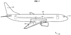
- FIG. 1 illustrates the structure of an exemplary aircraft that may utilize fasteners according to the present invention.
- FIG. 1 is a diagram of an aircraft 100.
- Aircraft 100 includes nose 110, wings 120, fuselage 130, and tail 140.
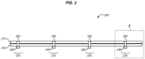
- FIG. 2 is a cut-through view of a section of wing skin 200 of aircraft 100 indicated by view arrows 2 in FIG. 1 .
- wing skin 200 comprises multiple composite or metal parts (210, 220), which include holes 230.
- Fasteners 250 are driven through holes 230 (e.g., to form an interference fit), and are secured with securements 240 (e.g., swaged-on collars or threaded nuts). Securements 240 may be swaged onto fasteners 250 at locations where pintails have been broken off of fasteners 250.
- Fasteners 250 may comprise pull-type lock bolts, stump-type lock bolts, HI-LOK brand pins, or any other type of permanent pin-type fastener.
- FIG. 3 is a zoomed-in view of a fastener 250 that attaches parts (210, 220) forming a section of skin 200.
- FIG. 3 corresponds with region 3 of FIG. 2 .
- FIG. 3 illustrates that each part may comprise a composite part including one or more layers/plies 310 (e.g., carbon fiber within a cured matrix of resin).
- parts 210 and 220 are metal.
- FIG. 3 further illustrates that within region 320, fastener 250 is placed into an interference fit with part 210. Although an interference fit is achieved, small air gaps (not shown) may still remain at certain locations between fastener 250 and part 210. These air gaps are caused by surface irregularities that may occur when drilling holes in composite materials.
- Fastener 250 may further include a coating that provides corrosion protection and enhanced lubricity.
- the coating may facilitate the installation of fastener 250, but may also electrically insulate fastener 250 from composite parts 210 and 220.
- the level of insulation is low enough so as to ensure a low dielectric withstand voltage, thereby ensuring that no substantial electrical arcing occurs between wall 330 of fastener 250, and wall 340 of composite part 210 in the event of an electrical discharge through region 320. While FIG. 3 illustrates fastener 250 being used for a composite-composite joint, fastener 250 may also be used for a metal-composite joint, or any suitable location.
- FIG. 4A is an additional view of fastener 250 and corresponds with region 4 of FIG. 3 .
- FIG. 4A illustrates a lock bolt configuration that is designed for installation with a swaged metallic collar (not shown).
- Fastener 250 further includes head 430, shank 440, lead-in transition 450, break groove 460, feature 470, and pintail 480 (including feature 482.
- Feature 470 and/or feature 482 can be annular shapes (e.g., rings), such that fastener 250 is forced into place by directly pushing fastener 250 into hole 230.
- Features 470 and/or 482 can be threaded.
- FIG. 1 illustrates a lock bolt configuration that is designed for installation with a swaged metallic collar (not shown).
- Fastener 250 further includes head 430, shank 440, lead-in transition 450, break groove 460, feature 470, and pintail 480 (including feature 482.
- Feature 470 and/or feature 482 can be annular shapes (e
- FIGS. 4A-4B illustrates a fastener 250 implemented as a threaded fastener, including slots 410 and 420 (e.g., hexagonal female slots, prismatic "star drive”/TORX slots, or other suitable slots that facilitate installation of fastener 250 into hole 230).
- Feature 470 can comprise threads designed to accommodate a threaded collar or nut (not shown).
- FIGS. 4A-4B further illustrate coating coverage area 490, where a high-lubricity coating (e.g., a metal pigment coating or dry film lubricant) is applied in a non-uniform discontinuous manner to fastener 250. Areas of fastener 250 other than the head 430 and shank 440 may be fully coated with high-lubricity coatings in order to facilitate fastener installation.
- a high-lubricity coating e.g., a metal pigment coating or dry film lubricant
- FIG. 5 is a close-up view of coating coverage area 490 of fastener 250 of FIGS. 4A and 4B .
- coating 510 e.g., an Al or Cu metal pigment coating, a coating of dry-film lubricant such as molybdenum disulfide, etc.
- the coating coverage area 490 may encompass the bearing portion of the fastener, including fastener head 430and shank 440, stopping at fastener lead-in transition 450.
- the surface of coating coverage area 490 may comprise bare metal (e.g., titanium or a ferrous or nickel-base alloy having enhanced properties of electrical conduction) or a finish (e.g., anodize).
- FIG. 1 is a close-up view of coating coverage area 490 of fastener 250 of FIGS. 4A and 4B .
- coating 510 e.g., an Al or Cu metal pigment coating, a coating of dry-film lubricant such as molybdenum disulfide, etc.
- FIG. 5 illustrates regions 522 of the coating coverage area 490 where some of the original surface/finish 520 of fastener 250 remains visible after application of the high-lubricity coating. Areas of fastener head 430 that are not in contact with hole 230 after installation need not receive coating 510.
- Coating 510 beneficially increases the lubricity (and/or corrosion resistance) of fastener 250 when compared with commonly used fastener finishes or bare metal.
- coating 510 is applied on the surface 520 of shank 440, a majority of sliding friction force endured by fastener 250 during installation is borne by coating 510.
- the portions of shank 440 covered by coating 510 are among the regions of the fastener 250 needing the highest amount of lubricity during fastener insertion into hole 230 for an installed state of interference.
- shank 440 may slide into hole 230 along its most lubricious portions, reducing the amount of force involved in installing fastener 250.
- coating 510 may not provide sufficient conductivity to ensure that fastener 250 properly dissipates electrical energy.
- a coating 510 formed from metal pigment coating may have a dielectric withstand voltage in the range of zero to two thousand volts, as compared with anodized metal having a dielectric withstand voltage in the range of zero to sixty volts, or some other intrinsically low voltage. This means that a uniform metal pigment coating on shank 440 would cause shank 440 to experience high voltage discharges of electrical energy (e.g., discharges of about two thousand volts), which is undesirable.
- coating 510 is desirable to ensure compatibility with structural design constraints, coating 510 exacerbates issues pertaining to electrical constraints because it exhibits less than a desired level of electrical energy conduction.
- shank 440 and/or head 430 are discontinuously coated in an irregular, non-uniform and/or unpatterned mosaic 590 application of coating 510.
- This technique is beneficial in that it eliminates any need to mask fastener 250 (e.g., in order to apply solid stripes or strips of coating 510), which removes a step involved in the fabrication of fasteners 250 and therefore reduces cost. Furthermore, this technique balances concerns related to electrical and structural design constraints.
- US 2016/0169262 A1 discloses a metal screw for interference fits in composite materials for aircraft, which fastener is provided with regularly alternating, separate electrically conductive strips and lubricating strips.
- US 2015/0147136 A1 discloses a fixing member for securing aircraft elements together, which fixing member is provided with separate strips of electrically conductive layers and lubricating layers made of different materials.
- coating 510 may be applied via spraying to form a speckled/spattered film on head 430 and/or shank 440.
- a speckled/spattered arrangement comprises a random distribution of coating across the entire perimeter of head 430 and/or shank 440.
- the percentage of surface area of shank 440 (and/or head 430) covered by coating 510 may be varied as a matter of design choice to between thirty and seventy percent. The percentage may even vary along the axial length of fastener 250.
- the percentage area of coating 510 may be increased for fasteners that would otherwise require high amounts of force to install (e.g., fasteners having long grip lengths/axial lengths for shanks 440, or fasteners having shanks with larger diameters).
- the percentage area of coating 510 may be decreased for fasteners that are exposed to higher electrical currents and where fastener 250 insertion force requirements may be less demanding.
- the percentage area of coating 510 on shank 440 may also vary depending on whether or not surface 520 features a finish (e.g., anodize) or is bare metal. If surface 520 is bare metal, more coating 510 may be allowed while still conforming with electrical constraints, but more coating 510 may also be needed to ensure that the amount of force used to overcome friction with laminate plies does not exceed a predefined amount. As noted above, if fastener 250 is driven with too much force, it may damage underlying structural components (e.g., by delaminating those components in the region around hole 230 and causing ply separation). In a similar fashion, if surface 520 is anodized, less coating 510 may be allowed to conform with structural constraints, but less coating 510 may also be needed to ensure sufficient dispersion of electrical energy.
- a finish e.g., anodize
- Lubricant 530 is shown in addition to coating 510.
- Lubricant 530 is applied to fastener 250 (e.g., via a dip or spray).
- Lubricant 530 is applied after coating 510 is speckled on.
- lubricant 530 may be applied to shank 440 or the entirety of fastener 250.
- lubricant 530 differs substantially from coating 510 in that lubricant 530 is not fused, baked, or otherwise firmly adhered onto/integral with fastener 250.
- lubricant 530 comprises a traditional lubricant (e.g., an oil, cetyl alcohol, wax, sealant etc.) which acts as a sacrificial lubricant during installation.
- lubricant 530 alone (e.g., without coating 510) is insufficient to ensure that the driving force applied to fastener 250 will be below a desired threshold level of friction.
- the interference contact involved in an interference fit ensures that lubricant 530 will be scraped off during installation, meaning that coating 510 defines in large degree the amount of installation force used for fastener 250.
- lubricant 530 may be considered an optional complement to coating 510, but does not replace the role of coating 510.
- FIG. 5 further illustrates an additional and/or alternative coating/finish that may be applied to lead-in portion/transition 450.
- Coating 510 may further continue into region 595, including lead-in transition 450.
- a different high-lubricity coating may be utilized in region 595 than coating 510.
- the coverage of region 595 by coating 510 may be complete (e.g., as shown) in order to fully cover the circumference of lead-in transition 450. In another embodiment, the coverage may be speckled in a similar manner as described above for shank 440.
- FIG. 6 illustrates a further view of fastener 250 after fastener 250 has been installed at skin 200 of aircraft 100.
- the force of installing fastener 250 (by forcing fastener 250 in direction D into a hole of a smaller diameter has caused portions of coating 510 to shear, resulting in coating 510 having a smeared appearance 600.
- notes regarding a desired percentage of surface area occupied by coating 510 are directed towards the amount of surface area occupied by coating 510 prior to installation.
- fastener 250 Illustrative details of the fabrication and operation of fastener 250 will be discussed with regard to FIGS. 7-8 .
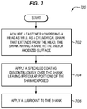
- FIG. 7 is a flowchart illustrating a method 700 for fabricating a fastener 250 in an exemplary embodiment.
- the steps of method 700 are described with reference to fastener 250 of FIG. 1 , but those skilled in the art will appreciate that method 700 may be performed for other fasteners (e.g., bolts, screws, rivets, etc.) in order to achieve a desired result.
- the steps of the flowcharts described herein are not all inclusive and may include other steps not shown. The steps described herein may also be performed in an alternative order.
- fastener 250 is acquired, including head 430 and cylindrical shank 440 (step 702).
- Shank 440 includes surface 520, which may be bare metal or anodized metal.
- fastener 250 may be forged from a titanium, ferrous alloy, or nickel alloy form, or may be machined from a precursor part.
- fastener 250 may be acquired from a supplier that manufactures fasteners in volume.
- the fastener 250 may furthermore comprise a finish over part of, or the entirety of its surface.
- a high lubricity coating 510 is speckled over shank 440 (step 704).
- Coating 510 may further be applied to head 430 in a similar manner.
- Coating 510 is discontinuously applied (e.g. speckled) over irregular (e.g., randomly shaped) portions of head 430 and/or shank 440, and leaving irregular portions of shank 440 exposed.
- This forms an unpatterned mosaic of spattered/speckled coverage arrangement across the surface of shank 440 (e.g., across the entire circumference of shank 440 and/or the entire circumference of head 430, and extending axially), ensuring that a desired percentage of the surface area of shank 440 is covered by coating 510.
- coating 510 enhances the lubricity of shank 440, reducing the amount of effort used in installing shank 440 in an interference fit into hole 230. This in turn helps in overcoming interference fit friction.
- coating 510 were applied across the entirety of shank 440 in a manner that completely covered the entire surface of shank 440, coating 510 would be electrically insulated from parts 210 and 220, resulting in diminished capability of fastener 250 to disperse electrical energy.
- coating 510 in a non-uniform, irregular manner provides a further and seemingly paradoxical benefit in that coating 510 remains, on average, evenly distributed along the entire circumference of shank 440, even though the specific regions occupied by coating 510 are random.
- no portion of the circumference of shank 440 e.g., 30o, 60o, 90o, 120o, etc.
- has a substantially different ratio of coating 510 to exposed surface 520 e.g., the ratio of these components remains substantially the same/constant as the circumference is traversed, such as within ten percent of a desired value).
- fastener 250 includes a more uniform lubricity (on an area-by-area basis). Fastener 250 therefore achieves better lubricity than striped fasteners, and the cost of manufacture is less than that for striped fasteners, which require masking. Furthermore, unlike a striped system, electrical current does not have to flow past large solid coated areas/stripes at fastener 250 in order to reach a region where dissipation of electrical energy may occur.
- fastener 250 exhibits more uniform/better electrical energy dissipation capability (e.g., dielectric withstand voltages) along its circumference (on average) than striped fasteners.
- Coating 510 marginally increases the width/diameter of fastener 250. Accordingly the radius of the coated shank is therefore also greater than the radius of the non-coated shank.
- coating 510 may increase the width of fastener 250 by several thousandths of an inch (i.e., less than one hundredth of an inch). This means that the diameter of the coated fastener is not consistent as the coating is not consistent. However, the added thickness has no substantial impact on installation.
- the coating 510 increases the diameter of the shank, so that the coating 510 extends beyond the surface of the shank at the exposed, irregular portions of the shank free of coating. As such, the coating 510 creates peaks which project from and extend away from the surface of the shank. The shank is not polished after application of the coating.
- Coating 510 may consist of a high-lubricity metal-pigmented organic material or a dry-film lubricant.
- Coating 510 may be thermally processed (e.g., cured) after application to ensure that coating 510 is heat-fused to shank 440 and is not rubbed off or otherwise perturbed (except for example when shank 440 is fit into hole 230).
- speckling comprises physically spattering coating 510 over shank 440. This means that no masking is needed.
- lubricant 530 e.g., cetyl alcohol
- fastener 250 may be dipped and/or uniformly sprayed with lubricant 530 (i.e., saturated, resulting in no irregularities in coverage) in order to cover fastener 250.
- lubricant 530 may be sacrificial in nature, rubbing off during the installation of fastener 250, and thereby ensuring minimal interference with (e.g., insulation of) the conductivity of shank 440.
- Method 700 may be performed via batch processes of forming, machining, spraying, and/or dipping in order to ensure sufficient throughput of fasteners 250 for aircraft manufacturing. Since no masking is required (e.g., since fastener 250 is not masked and then sprayed with solid stripes of continuous coating 510), the amount of labor and time involved in the manufacture of fasteners 250 is reduced.
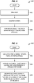
- FIG. 8 is a flowchart illustrating a method 800 for installing a fastener 250 using a semi-automated or manual assembly process in an exemplary embodiment.
- a hole of a predetermined diameter is drilled into an aircraft (e.g., by an automated machine in accordance with a Numerical Control (NC) program, by a technician, etc.) (step 802).
- a fastener 250 is acquired by the machine having an appropriate diameter and grip length (step 804).
- the diameter may be chosen such that it is larger (e.g., by several thousandths of an inch) than the hole.
- the fastener insertion machine may consist of a machine end effector that may operate according to a Numerical Control (NC) program implemented by a controller/processor in order to select a hole 230 into which to install fastener 250.
- hole 230 is located at a fuel tank of an aircraft. The diameter of the hole 230 is sized such that when fastener 250 is installed, a prescribed level of interference is attained within tolerance. With a hole 230 chosen, the fastener insertion machine forms an interference fit between shank 440 and hole 230, by driving/inserting shank 440 into hole 230 (step 806).
- This operation may be performed by torqueing shank 440 into hole 230 via feature 470 (e.g., threading), or by directly forcing shank 440 into place.
- Shank 440 may be held in hole 230 after insertion to prevent rotation. This may be performed for example during installation of a securement 240 (e.g., a nut) onto fastener 250. After a number of fasteners 250 have been installed in this manner, an operator then follows by installing collars or nuts using hand-held or automated tools as desired. In all cases, since shank 440 is partially covered with coating 510, the lubricity of shank 440 is enhanced, reducing the amount of installation force used.
- fastener 250 With shank 440 in place in an interference fit, fastener 250 performs its role of fastening desired structural components (e.g., composite or metal parts that each form a portion of skin 200). Steps 802-806 may be repeated multiple times (e.g., hundreds or thousands of times) during the manufacturing of aircraft 100, in order to fasten the various components of aircraft 100. Upon aircraft 100 being fully manufactured, it may then be operated in flight.
- desired structural components e.g., composite or metal parts that each form a portion of skin 200.
- Methods 700-800 utilize fasteners that exhibit an advantage over prior coated fastener systems in that fasteners 250 ensures that structural requirements of lubricity are met, while also ensuring that fasteners 250 safely dissipate electrical energy. Compared to fasteners sheathed in metallic sleeves, another system sometimes used in similar applications, methods 700-800 provide a one piece fastener at much lower cost.
- EP 2947 015 A1 discloses a modified shank fastener, the object of which is to do away with the need for extra sleeves provided between the fastener and the hole in a composite joint, for dissipating electrical/lightning strike energy.
- the shank disclosed in EP 2947 015 A1 is provided with a roughened surface, formed by knurling/machining, which roughened surface is then provided with a dry lubricant coating.
- the knurled shank is then polished to remove coating from the knurl peaks, but to leave a regular coating in the knurl valleys. The coating and the knurl peaks are evened out to be level with each other on the polished surface of the shank fastener, whereby the peaks are removed.
- FIG. 9 is a flowchart illustrating a method 900 for dissipating electrical energy between a fastener 250 and a hole 230.
- Electrical energy builds up between fastener 250 and hole 230 (step 902). This may occur for example during flight.
- the built-up electrical energy traverses around coating 510, which covers surface 520 of fastener 250 (step 904). Since coating 510 exhibits a higher dielectric withstand voltage than surface 520, electrical energy passes around coating 510 instead of passing into fastener 250 via coating 510.
- electrical energy is dissipated between surface 520 of shank 440 and hole 230 (step 906). This action is performed discontinuously along the entire circumference (i.e., the entire 360o) of shank 440 at irregular portions, any may occur at each location that is not coated by coating 510.
- a sprayer may be calibrated to adjust the size of individual spots/speckles applied to fastener 250. For example, in order to ensure that randomly applied speckles do not substantially vary in terms of the percentage of surface area occupied in a given portion of fastener 250, it may be desirable to select spot sizes that are between approximately one tenth and one thousandth the circumference of fastener 250.
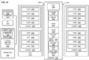
- FIG. 10 is a block diagram of a fastener 1040 and accompanying machinery in an exemplary embodiment.
- FIG. 10 illustrates a titanium pull-type lock bolt fastener 1040 which includes head 1041.
- Fastener 1040 further includes shank 1043, which itself includes surface 1044 (e.g., an anodized or bare metal surface) and high-lubricity coating 1045.
- Coating 1045 is applied discontinuously, irregularly, and or in a non-uniform fashion (e.g., randomly) upon head 1041 and shank 1043, leaving irregular portions of surface 1044 exposed while other portions of surface 1044 are covered. Coating 1045 application is accomplished during fastener 1040 fabrication using automated spray equipment.
- Fastener 1040 further includes lead-in transition 1046, which gradually reduces in diameter as it extends from shank 1043 into features 1047 (e.g., threading). Break groove 1049 is also illustrated. Feature 1047 and pintail 1052 are separated by neck/break groove 1049. Pintail 1052 includes feature 1050 (e.g., annular rings) that allow a swaging tool to engage the fastener 1040 and keep the joint clamped during collar 1053 installation and swaging. Pintail 1052 will be broken off after installation of fastener 1040, and pintail 1052 includes feature 1050 as well as slot 1051. Fastener 1040 is covered in lubricant 1060. During installation, collar 1053 will be swaged onto feature 1047, locking fastener 1040 in place.
- lead-in transition 1046 which gradually reduces in diameter as it extends from shank 1043 into features 1047 (e.g., threading).
- Break groove 1049 is also illustrated. Feature 1047 and pintail 1052 are separated
- FIG. 10 Further components illustrated in FIG. 10 include parts 1070 comprising laminates 1080 which each comprise individual plies 1082. In some areas, one or more of the structural parts 1070 being joined may be metallic. Assembly equipment may include numerically-controlled drilling and fastener insertion machines 1090 and hand-held fastener insertion tools and swaging tools 1095. Die 1010 (from which fastener 1040 is formed), sprayer 1030 (which applies coating 1045 to shank 1043 by spraying metal pigment coating (e.g., an aluminum-pigmented coating) from reservoir 1034 via orifice 1036), and fastener insertion machine 1090 (which installs fastener 1040) are also illustrated. The operations of fastener insertion machine 1090 and/or sprayer 1030 may be directed by controller 1022 in accordance with a stored NC program 1024.
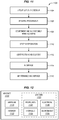
- exemplary method 1100 may include specification and design 1104 of the aircraft 1102 and material procurement 1106.
- component and subassembly manufacturing 1108 and system integration 1110 of the aircraft 1102 takes place.
- the aircraft 1102 may go through certification and delivery 1112 in order to be placed in service 1114.
- routine maintenance and service 1116 which may also include modification, reconfiguration, refurbishment, and so on).
- Apparatus and methods disclosed herein may be employed during any one or more suitable stages of the production and service method 1100 (e.g., specification and design 1104, material procurement 1106, component and subassembly manufacturing 1108, system integration 1110, certification and delivery 1112, service 1114, maintenance and service 1116) and/or any suitable component of aircraft 1102 (e.g., airframe 1118, systems 1120, interior 1122, propulsion 1124, electrical 1126, hydraulic 1128, environmental 1130).
- any suitable component of aircraft 1102 e.g., airframe 1118, systems 1120, interior 1122, propulsion 1124, electrical 1126, hydraulic 1128, environmental 1130.
- a system integrator may include without limitation any number of aircraft manufacturers and major-system subcontractors; a third party may include without limitation any number of vendors, subcontractors, and suppliers; and an operator may be an airline, leasing company, military entity, service organization, and so on.
- the aircraft 1102 produced by exemplary method 1100 may include an airframe 1118 with a plurality of systems 1120 and an interior 1122.
- high-level systems 1120 include one or more of a propulsion system 1124, an electrical system 1126, a hydraulic system 1128, and an environmental system 1130. Any number of other systems may be included.
- an aerospace example is shown, the principles of the invention may be applied to other industries, such as the automotive industry.
- the present invention may be employed during any one or more of the stages of the production and service method 1100.
- components or subassemblies corresponding to production stage 1108 may be fabricated or manufactured in a manner similar to components or subassemblies produced while the aircraft 1102 is in service.
- one or more apparatus embodiments, method embodiments, or a combination thereof may be utilized during the production stages 1108 and 1110, for example, by substantially expediting assembly of or reducing the cost of an aircraft 1102.
- one or more of apparatus embodiments, method embodiments, or a combination thereof may be utilized while the aircraft 1102 is in service, for example and without limitation, to maintenance and service 1116.
- the techniques and systems described herein may be used for steps 1106, 1108, 1110, 1114, and/or 1116, and/or may be used for airframe 1118 and/or interior 1122. These techniques and systems may even be utilized for systems 1120, including for example propulsion 1124, electrical 1126, hydraulic 1128, and/or environmental 1130.
- Fastener 250 may secure portions of airframe 1118, and is manufactured during component and subassembly manufacturing 1108. Fastener 250 may then be secured in order to fasten components of airframe 1118 during system integration 1110, and then be utilized in service 1114 until wear renders fastener 250 unusable. Then, in maintenance and service 1116, fastener 250 may be discarded and replaced with a newly manufactured part.
- control elements e.g., electrical or electronic components
- a processor implementing software
- a processor implementing firmware or some combination of these.
- an element may be implemented as dedicated hardware.
- Dedicated hardware elements may be referred to as "processors", “controllers”, or some similar terminology.
- the functions may be provided by a single dedicated processor, by a single shared processor, or by a plurality of individual processors, some of which may be shared.
- processor or “controller” should not be construed to refer exclusively to hardware capable of executing software, and may implicitly include, without limitation, digital signal processor (DSP) hardware, a network processor, application specific integrated circuit (ASIC) or other circuitry, field programmable gate array (FPGA), read only memory (ROM) for storing software, random access memory (RAM), non-volatile storage, logic, or some other physical hardware component or module.
- DSP digital signal processor
- ASIC application specific integrated circuit
- FPGA field programmable gate array
- ROM read only memory
- RAM random access memory
- non-volatile storage logic, or some other physical hardware component or module.
- a control element may be implemented as instructions executable by a processor or a computer to perform the functions of the element.
- instructions are software, program code, and firmware.
- the instructions are operational when executed by the processor to direct the processor to perform the functions of the element.
- the instructions may be stored on storage devices that are readable by the processor. Some examples of the storage devices are digital or solid-state memories, magnetic storage media such as a magnetic disks and magnetic tapes, hard drives, or optically readable digital data storage media.
Description
- The disclosure relates to the field of fasteners, and in particular, to fasteners that disperse electrical energy.
- Fasteners are used in the aerospace industry to mechanically unite various structural components of an aircraft. For example, composite or metal panels that form a portion of a skin of an aircraft wing may be joined to one another via a fastener. In aircraft structures, it is often desirable to install fasteners in interference, meaning that the fastener diameter is larger than the diameter of the hole that receives it. Interference-fit installation of fasteners can facilitate aircraft assembly operations and improve joint performance. As fasteners are intended to enhance the structural strength of an aircraft, it remains desirable to ensure that the act of installing a fastener does not damage underlying structural components of the aircraft. In particular, if an interference-fit fastener is forced through a composite part with too much force, it may cause the composite part to delaminate or experience other issues. Thus, an interference fit fastener may utilize a lubricant that reduces the amount of force used to drive the fastener during installation. Excessive force may also result in damage to the fastener and, in joints comprised of metal and composite parts, it can additionally result in detrimental galling, scoring or excessive deformation of the metal parts. The magnitude of the fastener insertion force may be controlled by the application of lubricants to the fastener or to the hole, by limiting the amount of interference, or by using means other than driving or pulling the fastener into the hole to create the desired state of interference.
- Although structural strength of a fastener is important to consider, it is also important for fasteners to adequately conduct and/or disperse electrical energy from the surrounding structure. Hence, it remains important for the fastener to efficiently disperse electrical energy to surrounding structural components in a manner that prevents energy from building at the fastener.
- While both structural strength and electrical compatibility remain desirable, it is a complicated process to balance both of these requirements when designing a fastener. For example, a fastener may be coated in order to enhance lubricity and therefore reduce the amount of force used to install the fastener. However, coatings, and/or finishes may electrically insulate the fastener from its surroundings, thereby confounding the ability of the fastener to adequately dissipate electrical energy. As another example, using fasteners sheathed in a protective metal sleeve may provide an adequate level of energy dissipation and reduce the possibility of damaging composite parts during fastener installation. However, such fasteners can be generally costly.
- For at least these reasons, designers continue to seek out fastener designs that strike a balance in fulfilling both structural and electrical design constraints.
- The prior art includes
US 2013/01831119 A1 US 2013/183119 A1 is not an interference fit fastener. - The present invention concerns the application of irregular (e.g., speckled/spattered) coatings, for example metal pigmentation coatings onto fasteners in regions where the fasteners will be installed into a hole in a state of interference. For example, the fasteners may comprise pull-type lock bolts that include a shank dimensioned for an interference fit with structural components of an aircraft. The surface of the fastener may be bare, or may be coated partially or in its entirety with a finish (e.g., anodize, or a finish formed from bare metal via grit blasting etc.). Additionally, a portion of the fastener is coated in an irregular (i.e., unpatterned) high-lubricity coating, such as a metal pigmentation coating and/or a dry film lubricant coating, such that the coating is randomly interspersed with regions of bare (or finished) metal. In this manner, application of the coating enhances lubricity without substantially compromising electrical conductivity of the fastener. This is because remaining exposed regions not covered by the coating (e.g., regions of bare or anodized metal) provide desired levels of electrical energy dispersion at the fastener surface discontinuously along the entire circumference (i.e., all 360º) of the fastener.
- In particular the present invention provides a method for providing a fastener for use in the aerospace or similar industry, the method comprising the steps of:
- providing a fastener comprising:
- a head,
- a cylindrical shank that extends from the head and is dimensioned to engage in a fit with a corresponding hole,
- which cylindrical shank has a surface and,
- spraying, with a sprayer, a coating in a non-uniform, discontinuous manner onto the fastener in order to leave irregular portions of the surface of the shank exposed and free of coating, and also in order to leave irregular portions of the surface of the shank covered in coating,
- wherein the coating exhibits a higher lubricity than the surface of the shank so that the irregular, coating covered portions of the surface of the shank exhibit a higher lubricity than the irregular portions of the surface of the shank exposed and free of coating and,
- wherein the coating exhibits a higher dielectric withstand voltage than the surface of the shank so that charge dissipates via the irregular portions of the surface of the shank exposed and free of coating before the dielectric withstand voltage of the coating, of the irregular, covered portions of the surface of the shank is met,
- wherein the pressure, time of exposure and/or orifice size for the sprayer is adjusted in order to adjust the percentage covering of surface area of the shank covered by coating as a matter of design choice.
- The coating preferably comprises an Al or Cu metal pigment coating and/ or a molybdenum disulfide coating.
- The surface of the shank may be anodized prior to spraying the coating over the shank.
- A lubricant may be applied that covers the shank which lubricant is applied after the coating has been applied, which lubricant is preferably not fused, baked, or otherwise firmly adhered onto/or integral with the fastener and which lubricant can act as a sacrificial lubricant during installation of the fastener and which lubricant preferably comprises cetyl alcohol.
- The step of coating spraying also preferably sprays coating onto a circumference of the fastener head
- Applying the coating may increase a width of the shank by less than 0.0254 cm (one hundredth of an inch) and the radius of the coated shank is greater than the radius of the non-coated shank.
- The coating sprayer is preferably calibrated to adjust the size of individual spots or speckles of coating sprayed onto the fastener wherein for example the sprayer is calibrated to spray spots of coating that are between approximately one tenth and one thousandth the circumference of the fastener.
- The pressure, time of exposure and/or orifice size for the sprayer can be adjusted in order to adjust the percentage covering of surface area of the shank covered by coating as a matter of design choice to preferably between 30% and 70%.
- The invention further specifically relates to a fastener, as preferably provided by this method, for use in the aerospace or similar industry, the fastener comprising:
- a head;
- a cylindrical shank that extends from the head and is dimensioned to engage in a fit with a corresponding hole; which cylindrical shank has a smooth surface and a diameter,
- a coating wherein the coating is applied in a non-uniform, discontinuous manner to the fastener to thereby leave the surface of the shank with irregular portions exposed and free of coating, and also to thereby leave the surface of the shank with irregular portions covered in coating,
- whereby the coating increases the diameter of the shank and forms peaks on the smooth surface of the shank, wherein the coating exhibits a higher lubricity than the surface of the shank so that the irregular, coating covered portions of the surface of the shank exhibit a higher lubricity than the irregular portions of the surface of the shank exposed and free of coating and,
- wherein the coating exhibits a higher dielectric withstand voltage than the surface of the shank so that charge dissipates via the irregular portions of the surface of the shank exposed and free of coating before the dielectric withstand voltage of the coating covering the irregular, coating covered portions of the surface of the shank is met.
- The surface of the shank preferably comprises a finish, for example an anodized surface.
- The shank is preferably made of a material selected from the group consisting of titanium, ferrous alloy, and nickel alloy.
- The coating may comprise an Al or Cu metal pigment coating and/or a molybdenum disulfide coating.
- The fastener can further comprise a lubricant covering the shank and the coating, which lubricant is preferably not firmly adhered to the fastener so that the lubricant acts as a sacrificial lubricant during installation of the fastener and which lubricant preferably comprises cetyl alcohol.
- The coating is also preferably in the non-uniform, discontinuous manner to the fastener head during spraying, to thereby leave the fastener head with irregular portions exposed and free of coating and also to thereby leave the fastener head with irregular portions covered in coating, preferably wherein areas of the fastener head that are not in contact with the hole after installation are not coated.
- The coating can increase a width of the shank by less than 0.0254 cm (one hundredth of an inch).
- The radius of the coated shank can be greater than the radius of the non-coated shank.
- The coating preferably covers between 30% and 70% of a surface area of the shank.
- The fastener is also preferably unmasked.
- The present invention is now described, by way of example only, and with reference to the accompanying drawings. The same reference number represents the same element or the same type of element on all drawings.
-
FIG. 1 is a diagram of an aircraft. -
FIG. 2 is a cut-through view of a section of skin of a wing including fasteners according to the present invention. -
FIG. 3 is a zoomed-in view of a fastener according to the present invention. -
FIG. 4A-4B are additional views of fasteners according to the present invention. -
FIG. 5 is a zoomed in view of a discontinuous coating applied to a fastener according to the present invention. -
FIG. 6 is a zoomed in view of a smeared discontinuous coating at an installed fastener according to the present invention. -
FIG. 7 is a flowchart illustrating a method for fabricating a fastener according to the present invention. -
FIG. 8 is a flowchart illustrating a method for installing a fastener according to the present invention. -
FIG. 9 is a flowchart illustrating a method for exchanging electrical energy between a fastener and hole according to the present invention. -
FIG. 10 is a block diagram of a fastener according to the present invention. -
FIG. 11 is a flow diagram of aircraft production and service methodology according to the present invention. -
FIG. 12 is a block diagram of an aircraft according to the present invention. - The figures and the following description illustrate the present invention.
-
FIG. 1 illustrates the structure of an exemplary aircraft that may utilize fasteners according to the present invention. Specifically,FIG. 1 is a diagram of anaircraft 100.Aircraft 100 includesnose 110,wings 120,fuselage 130, andtail 140. -
FIG. 2 is a cut-through view of a section ofwing skin 200 ofaircraft 100 indicated by view arrows 2 inFIG. 1 . As shown inFIG. 2 ,wing skin 200 comprises multiple composite or metal parts (210, 220), which include holes 230.Fasteners 250 are driven through holes 230 (e.g., to form an interference fit), and are secured with securements 240 (e.g., swaged-on collars or threaded nuts).Securements 240 may be swaged ontofasteners 250 at locations where pintails have been broken off offasteners 250.Fasteners 250 may comprise pull-type lock bolts, stump-type lock bolts, HI-LOK brand pins, or any other type of permanent pin-type fastener. -
FIG. 3 is a zoomed-in view of afastener 250 that attaches parts (210, 220) forming a section ofskin 200.FIG. 3 corresponds with region 3 ofFIG. 2 .FIG. 3 illustrates that each part may comprise a composite part including one or more layers/plies 310 (e.g., carbon fiber within a cured matrix of resin). In further examples,parts FIG. 3 further illustrates that withinregion 320,fastener 250 is placed into an interference fit withpart 210. Although an interference fit is achieved, small air gaps (not shown) may still remain at certain locations betweenfastener 250 andpart 210. These air gaps are caused by surface irregularities that may occur when drilling holes in composite materials. These small air gaps in turn insulate small portions offastener 250 fromcomposite part 210.Fastener 250 may further include a coating that provides corrosion protection and enhanced lubricity. The coating may facilitate the installation offastener 250, but may also electrically insulatefastener 250 fromcomposite parts wall 330 offastener 250, andwall 340 ofcomposite part 210 in the event of an electrical discharge throughregion 320. WhileFIG. 3 illustratesfastener 250 being used for a composite-composite joint,fastener 250 may also be used for a metal-composite joint, or any suitable location. -
FIG. 4A is an additional view offastener 250 and corresponds withregion 4 ofFIG. 3 .FIG. 4A illustrates a lock bolt configuration that is designed for installation with a swaged metallic collar (not shown).Fastener 250 further includes head 430,shank 440, lead-intransition 450, breakgroove 460, feature 470, and pintail 480 (includingfeature 482.Feature 470 and/or feature 482 can be annular shapes (e.g., rings), such thatfastener 250 is forced into place by directly pushingfastener 250 intohole 230.Features 470 and/or 482 can be threaded.FIG. 4B illustrates afastener 250 implemented as a threaded fastener, includingslots 410 and 420 (e.g., hexagonal female slots, prismatic "star drive"/TORX slots, or other suitable slots that facilitate installation offastener 250 into hole 230). Feature 470 can comprise threads designed to accommodate a threaded collar or nut (not shown).FIGS. 4A-4B further illustratecoating coverage area 490, where a high-lubricity coating (e.g., a metal pigment coating or dry film lubricant) is applied in a non-uniform discontinuous manner tofastener 250. Areas offastener 250 other than the head 430 andshank 440 may be fully coated with high-lubricity coatings in order to facilitate fastener installation. -
FIG. 5 is a close-up view ofcoating coverage area 490 offastener 250 ofFIGS. 4A and4B . Specifically,FIG. 5 illustrates that coating 510 (e.g., an Al or Cu metal pigment coating, a coating of dry-film lubricant such as molybdenum disulfide, etc.) may be discontinuously applied withinarea 490. Thecoating coverage area 490 may encompass the bearing portion of the fastener, including fastenerhead 430and shank 440, stopping at fastener lead-intransition 450. The surface ofcoating coverage area 490 may comprise bare metal (e.g., titanium or a ferrous or nickel-base alloy having enhanced properties of electrical conduction) or a finish (e.g., anodize).FIG. 5 illustratesregions 522 of thecoating coverage area 490 where some of the original surface/finish 520 offastener 250 remains visible after application of the high-lubricity coating. Areas of fastener head 430 that are not in contact withhole 230 after installation need not receivecoating 510. - Coating 510 beneficially increases the lubricity (and/or corrosion resistance) of
fastener 250 when compared with commonly used fastener finishes or bare metal. Ascoating 510 is applied on thesurface 520 ofshank 440, a majority of sliding friction force endured byfastener 250 during installation is borne bycoating 510. Fortunately, the portions ofshank 440 covered by coating 510 are among the regions of thefastener 250 needing the highest amount of lubricity during fastener insertion intohole 230 for an installed state of interference. Hence,shank 440 may slide intohole 230 along its most lubricious portions, reducing the amount of force involved in installingfastener 250. - While
coating 510 provides the above-noted benefits relating to fastener installation,coating 510 may not provide sufficient conductivity to ensure thatfastener 250 properly dissipates electrical energy. For example, acoating 510 formed from metal pigment coating may have a dielectric withstand voltage in the range of zero to two thousand volts, as compared with anodized metal having a dielectric withstand voltage in the range of zero to sixty volts, or some other intrinsically low voltage. This means that a uniform metal pigment coating onshank 440 would causeshank 440 to experience high voltage discharges of electrical energy (e.g., discharges of about two thousand volts), which is undesirable. Hence, althoughcoating 510 is desirable to ensure compatibility with structural design constraints, coating 510 exacerbates issues pertaining to electrical constraints because it exhibits less than a desired level of electrical energy conduction. - To address this issue, instead of uniformly coating the entirety of fastener 250 (or
shank 440 and head 430) withcoating 510, or applying solid regions (e.g., stripes) ofcoating 510 tofastener 250,shank 440 and/or head 430 are discontinuously coated in an irregular, non-uniform and/orunpatterned mosaic 590 application ofcoating 510. This technique is beneficial in that it eliminates any need to mask fastener 250 (e.g., in order to apply solid stripes or strips of coating 510), which removes a step involved in the fabrication offasteners 250 and therefore reduces cost. Furthermore, this technique balances concerns related to electrical and structural design constraints. -
US 2016/0169262 A1 discloses a metal screw for interference fits in composite materials for aircraft, which fastener is provided with regularly alternating, separate electrically conductive strips and lubricating strips. -
US 2015/0147136 A1 discloses a fixing member for securing aircraft elements together, which fixing member is provided with separate strips of electrically conductive layers and lubricating layers made of different materials. - An additional benefit exists in the use of a non-uniform coating. Specifically, coating 510 may be applied via spraying to form a speckled/spattered film on head 430 and/or
shank 440. As used herein, a speckled/spattered arrangement comprises a random distribution of coating across the entire perimeter of head 430 and/orshank 440. By adjusting a pressure, time of exposure, and/or orifice size for the sprayer, a percentage of surface area inarea 490 covered by coating 510 may be carefully adjusted. This enables the electrical and physical properties offastener 250 to be adjusted as desired. For example, the percentage of surface area of shank 440 (and/or head 430) covered by coating 510 may be varied as a matter of design choice to between thirty and seventy percent. The percentage may even vary along the axial length offastener 250. The percentage area ofcoating 510 may be increased for fasteners that would otherwise require high amounts of force to install (e.g., fasteners having long grip lengths/axial lengths forshanks 440, or fasteners having shanks with larger diameters). In contrast, the percentage area ofcoating 510 may be decreased for fasteners that are exposed to higher electrical currents and wherefastener 250 insertion force requirements may be less demanding. - The percentage area of
coating 510 onshank 440 may also vary depending on whether or not surface 520 features a finish (e.g., anodize) or is bare metal. Ifsurface 520 is bare metal,more coating 510 may be allowed while still conforming with electrical constraints, butmore coating 510 may also be needed to ensure that the amount of force used to overcome friction with laminate plies does not exceed a predefined amount. As noted above, iffastener 250 is driven with too much force, it may damage underlying structural components (e.g., by delaminating those components in the region aroundhole 230 and causing ply separation). In a similar fashion, ifsurface 520 is anodized,less coating 510 may be allowed to conform with structural constraints, butless coating 510 may also be needed to ensure sufficient dispersion of electrical energy. - In addition to
coating 510, anoptional lubricant 530 is shown.Lubricant 530 is applied to fastener 250 (e.g., via a dip or spray).Lubricant 530 is applied after coating 510 is speckled on. Furthermore,lubricant 530 may be applied toshank 440 or the entirety offastener 250. However,lubricant 530 differs substantially from coating 510 in thatlubricant 530 is not fused, baked, or otherwise firmly adhered onto/integral withfastener 250. Instead,lubricant 530 comprises a traditional lubricant (e.g., an oil, cetyl alcohol, wax, sealant etc.) which acts as a sacrificial lubricant during installation. That is, the majority oflubricant 530 is rubbed away/off or otherwise dissipated during installation, and hence the insulating properties oflubricant 530 do not substantially impact the electrical properties offastener 250. Since the installation offastener 250 involves an interference fit,lubricant 530 alone (e.g., without coating 510) is insufficient to ensure that the driving force applied tofastener 250 will be below a desired threshold level of friction. Specifically, the interference contact involved in an interference fit ensures thatlubricant 530 will be scraped off during installation, meaning thatcoating 510 defines in large degree the amount of installation force used forfastener 250. Hence,lubricant 530 may be considered an optional complement tocoating 510, but does not replace the role ofcoating 510.FIG. 5 further illustrates an additional and/or alternative coating/finish that may be applied to lead-in portion/transition 450. Coating 510 may further continue intoregion 595, including lead-intransition 450. A different high-lubricity coating may be utilized inregion 595 thancoating 510. The coverage ofregion 595 by coating 510 may be complete (e.g., as shown) in order to fully cover the circumference of lead-intransition 450. In another embodiment, the coverage may be speckled in a similar manner as described above forshank 440. -
FIG. 6 illustrates a further view offastener 250 afterfastener 250 has been installed atskin 200 ofaircraft 100. As shown inFIG. 6 , the force of installing fastener 250 (by forcingfastener 250 in direction D into a hole of a smaller diameter has caused portions ofcoating 510 to shear, resulting incoating 510 having a smearedappearance 600. This alters the arrangement ofcoating 510 onfastener 250, but does not substantially change the amount of surface area occupied bycoating 510. For the purposes of discussion, notes regarding a desired percentage of surface area occupied by coating 510 are directed towards the amount of surface area occupied by coating 510 prior to installation. - Illustrative details of the fabrication and operation of
fastener 250 will be discussed with regard toFIGS. 7-8 . -
FIG. 7 is a flowchart illustrating amethod 700 for fabricating afastener 250 in an exemplary embodiment. The steps ofmethod 700 are described with reference tofastener 250 ofFIG. 1 , but those skilled in the art will appreciate thatmethod 700 may be performed for other fasteners (e.g., bolts, screws, rivets, etc.) in order to achieve a desired result. The steps of the flowcharts described herein are not all inclusive and may include other steps not shown. The steps described herein may also be performed in an alternative order. - According to
method 700,fastener 250 is acquired, including head 430 and cylindrical shank 440 (step 702).Shank 440 includessurface 520, which may be bare metal or anodized metal. In one embodiment,fastener 250 may be forged from a titanium, ferrous alloy, or nickel alloy form, or may be machined from a precursor part. Alternatively,fastener 250 may be acquired from a supplier that manufactures fasteners in volume. Thefastener 250 may furthermore comprise a finish over part of, or the entirety of its surface. - A
high lubricity coating 510 is speckled over shank 440 (step 704). Coating 510 may further be applied to head 430 in a similar manner. Coating 510 is discontinuously applied (e.g. speckled) over irregular (e.g., randomly shaped) portions of head 430 and/orshank 440, and leaving irregular portions ofshank 440 exposed. This forms an unpatterned mosaic of spattered/speckled coverage arrangement across the surface of shank 440 (e.g., across the entire circumference ofshank 440 and/or the entire circumference of head 430, and extending axially), ensuring that a desired percentage of the surface area ofshank 440 is covered by coating 510. As discussed above, coating 510 enhances the lubricity ofshank 440, reducing the amount of effort used in installingshank 440 in an interference fit intohole 230. This in turn helps in overcoming interference fit friction. However, if coating 510 were applied across the entirety ofshank 440 in a manner that completely covered the entire surface ofshank 440, coating 510 would be electrically insulated fromparts fastener 250 to disperse electrical energy. - Applying
coating 510 in a non-uniform, irregular manner (e.g., an unpatterned manner) provides a further and seemingly paradoxical benefit in thatcoating 510 remains, on average, evenly distributed along the entire circumference ofshank 440, even though the specific regions occupied by coating 510 are random. In this manner, no portion of the circumference of shank 440 (e.g., 30º, 60º, 90º, 120º, etc.) has a substantially different ratio ofcoating 510 to exposed surface 520 (e.g., the ratio of these components remains substantially the same/constant as the circumference is traversed, such as within ten percent of a desired value). Thus, unlike a "striped" pattern of application forcoating 510 along the circumference offastener 250, which would necessarily cause uncoated regions to experience greater local amounts of friction (and therefore higher risk of damage) during insertion,fastener 250 includes a more uniform lubricity (on an area-by-area basis).Fastener 250 therefore achieves better lubricity than striped fasteners, and the cost of manufacture is less than that for striped fasteners, which require masking. Furthermore, unlike a striped system, electrical current does not have to flow past large solid coated areas/stripes atfastener 250 in order to reach a region where dissipation of electrical energy may occur. Hence,fastener 250 exhibits more uniform/better electrical energy dissipation capability (e.g., dielectric withstand voltages) along its circumference (on average) than striped fasteners. Coating 510 marginally increases the width/diameter offastener 250. Accordingly the radius of the coated shank is therefore also greater than the radius of the non-coated shank. - For example, coating 510 may increase the width of
fastener 250 by several thousandths of an inch (i.e., less than one hundredth of an inch). This means that the diameter of the coated fastener is not consistent as the coating is not consistent. However, the added thickness has no substantial impact on installation. Thecoating 510 increases the diameter of the shank, so that thecoating 510 extends beyond the surface of the shank at the exposed, irregular portions of the shank free of coating. As such, thecoating 510 creates peaks which project from and extend away from the surface of the shank. The shank is not polished after application of the coating. Coating 510 may consist of a high-lubricity metal-pigmented organic material or a dry-film lubricant. Coating 510 may be thermally processed (e.g., cured) after application to ensure thatcoating 510 is heat-fused toshank 440 and is not rubbed off or otherwise perturbed (except for example whenshank 440 is fit into hole 230). In one embodiment, speckling comprises physically spatteringcoating 510 overshank 440. This means that no masking is needed. - With coating 510 successfully applied, lubricant 530 (e.g., cetyl alcohol) is applied to fastener 250 (step 706). For example,
fastener 250 may be dipped and/or uniformly sprayed with lubricant 530 (i.e., saturated, resulting in no irregularities in coverage) in order to coverfastener 250. In embodiments wherelubricant 530 is cetyl alcohol,lubricant 530 may be sacrificial in nature, rubbing off during the installation offastener 250, and thereby ensuring minimal interference with (e.g., insulation of) the conductivity ofshank 440. -
Method 700 may be performed via batch processes of forming, machining, spraying, and/or dipping in order to ensure sufficient throughput offasteners 250 for aircraft manufacturing. Since no masking is required (e.g., sincefastener 250 is not masked and then sprayed with solid stripes of continuous coating 510), the amount of labor and time involved in the manufacture offasteners 250 is reduced. - With
fasteners 250 successfully fabricated, an aircraft manufacturer may desire to installfasteners 250 on an aircraft (e.g., aircraft 100). To this end,FIG. 8 is a flowchart illustrating amethod 800 for installing afastener 250 using a semi-automated or manual assembly process in an exemplary embodiment. According tomethod 800, a hole of a predetermined diameter is drilled into an aircraft (e.g., by an automated machine in accordance with a Numerical Control (NC) program, by a technician, etc.) (step 802). Afastener 250 is acquired by the machine having an appropriate diameter and grip length (step 804). The diameter may be chosen such that it is larger (e.g., by several thousandths of an inch) than the hole. This may be performed, for example, by loading a fastener (or batch of fasteners) into a fastener insertion machine (not shown). The fastener insertion machine may consist of a machine end effector that may operate according to a Numerical Control (NC) program implemented by a controller/processor in order to select ahole 230 into which to installfastener 250. In one embodiment,hole 230 is located at a fuel tank of an aircraft. The diameter of thehole 230 is sized such that whenfastener 250 is installed, a prescribed level of interference is attained within tolerance. With ahole 230 chosen, the fastener insertion machine forms an interference fit betweenshank 440 andhole 230, by driving/insertingshank 440 into hole 230 (step 806). This operation may be performed by torqueingshank 440 intohole 230 via feature 470 (e.g., threading), or by directly forcingshank 440 into place.Shank 440 may be held inhole 230 after insertion to prevent rotation. This may be performed for example during installation of a securement 240 (e.g., a nut) ontofastener 250. After a number offasteners 250 have been installed in this manner, an operator then follows by installing collars or nuts using hand-held or automated tools as desired. In all cases, sinceshank 440 is partially covered withcoating 510, the lubricity ofshank 440 is enhanced, reducing the amount of installation force used. Withshank 440 in place in an interference fit,fastener 250 performs its role of fastening desired structural components (e.g., composite or metal parts that each form a portion of skin 200). Steps 802-806 may be repeated multiple times (e.g., hundreds or thousands of times) during the manufacturing ofaircraft 100, in order to fasten the various components ofaircraft 100. Uponaircraft 100 being fully manufactured, it may then be operated in flight. - Methods 700-800 utilize fasteners that exhibit an advantage over prior coated fastener systems in that
fasteners 250 ensures that structural requirements of lubricity are met, while also ensuring thatfasteners 250 safely dissipate electrical energy. Compared to fasteners sheathed in metallic sleeves, another system sometimes used in similar applications, methods 700-800 provide a one piece fastener at much lower cost. -
EP 2947 015 A1 discloses a modified shank fastener, the object of which is to do away with the need for extra sleeves provided between the fastener and the hole in a composite joint, for dissipating electrical/lightning strike energy. The shank disclosed inEP 2947 015 A1 is provided with a roughened surface, formed by knurling/machining, which roughened surface is then provided with a dry lubricant coating. The knurled shank is then polished to remove coating from the knurl peaks, but to leave a regular coating in the knurl valleys. The coating and the knurl peaks are evened out to be level with each other on the polished surface of the shank fastener, whereby the peaks are removed. - With
fasteners 250 installed, operation of the aircraft 100 (e.g., during flight) may cause electrical energy to build atfastener 250. This energy may be the result of a lightning strike. This built-up charge continues to accumulate until it overcomes the dielectric withstand voltage ofsurface 520, at which point electrical energy betweenhole 230 andfastener 250 is dissipated at locations onsurface 520 When energy is dissipated atfastener 250, dissipation occurs between exposed portions ofsurface 520 andhole 230, and not betweencoating 510 andhole 230. Coating 510 may possess a higher dielectric withstand voltage thansurface 520. Charge may therefore dissipate viasurface 520 before the dielectric withstand voltage ofcoating 510 is met. This operation is beneficial, as dissipating charge through the relatively large area ofsurface 520 prevents the generation electrical arcs, for example limiting dissipation voltages to between about zero and sixty volts (preferably between zero and twenty volts). -
FIG. 9 is a flowchart illustrating amethod 900 for dissipating electrical energy between afastener 250 and ahole 230. Electrical energy builds up betweenfastener 250 and hole 230 (step 902). This may occur for example during flight. Next, the built-up electrical energy traverses aroundcoating 510, which coverssurface 520 of fastener 250 (step 904). Since coating 510 exhibits a higher dielectric withstand voltage thansurface 520, electrical energy passes aroundcoating 510 instead of passing intofastener 250 viacoating 510. Next, electrical energy is dissipated betweensurface 520 ofshank 440 and hole 230 (step 906). This action is performed discontinuously along the entire circumference (i.e., the entire 360º) ofshank 440 at irregular portions, any may occur at each location that is not coated bycoating 510. - In a further embodiment, a sprayer may be calibrated to adjust the size of individual spots/speckles applied to
fastener 250. For example, in order to ensure that randomly applied speckles do not substantially vary in terms of the percentage of surface area occupied in a given portion offastener 250, it may be desirable to select spot sizes that are between approximately one tenth and one thousandth the circumference offastener 250. - In the following examples, additional processes, systems, and methods are described in the context of a semi-automated titanium pull-type lock bolt fastener installation on the structure of an aircraft.
-
FIG. 10 is a block diagram of afastener 1040 and accompanying machinery in an exemplary embodiment. Specifically,FIG. 10 illustrates a titanium pull-typelock bolt fastener 1040 which includeshead 1041.Fastener 1040 further includesshank 1043, which itself includes surface 1044 (e.g., an anodized or bare metal surface) and high-lubricity coating 1045.Coating 1045 is applied discontinuously, irregularly, and or in a non-uniform fashion (e.g., randomly) uponhead 1041 andshank 1043, leaving irregular portions ofsurface 1044 exposed while other portions ofsurface 1044 are covered.Coating 1045 application is accomplished duringfastener 1040 fabrication using automated spray equipment.Fastener 1040 further includes lead-intransition 1046, which gradually reduces in diameter as it extends fromshank 1043 into features 1047 (e.g., threading).Break groove 1049 is also illustrated.Feature 1047 andpintail 1052 are separated by neck/break groove 1049.Pintail 1052 includes feature 1050 (e.g., annular rings) that allow a swaging tool to engage thefastener 1040 and keep the joint clamped duringcollar 1053 installation and swaging.Pintail 1052 will be broken off after installation offastener 1040, andpintail 1052 includesfeature 1050 as well asslot 1051.Fastener 1040 is covered inlubricant 1060. During installation,collar 1053 will be swaged ontofeature 1047, lockingfastener 1040 in place. - Further components illustrated in
FIG. 10 includeparts 1070 comprisinglaminates 1080 which each compriseindividual plies 1082. In some areas, one or more of thestructural parts 1070 being joined may be metallic. Assembly equipment may include numerically-controlled drilling andfastener insertion machines 1090 and hand-held fastener insertion tools andswaging tools 1095. Die 1010 (from whichfastener 1040 is formed), sprayer 1030 (which appliescoating 1045 toshank 1043 by spraying metal pigment coating (e.g., an aluminum-pigmented coating) fromreservoir 1034 via orifice 1036), and fastener insertion machine 1090 (which installs fastener 1040) are also illustrated. The operations offastener insertion machine 1090 and/orsprayer 1030 may be directed bycontroller 1022 in accordance with a storedNC program 1024. - Referring more particularly to the drawings, the present invention may be described in the context of an aircraft manufacturing and service method 1100 as shown in
FIG. 11 and anaircraft 1102 as shown inFIG. 12 . During pre-production, exemplary method 1100 may include specification anddesign 1104 of theaircraft 1102 andmaterial procurement 1106. During production, component andsubassembly manufacturing 1108 andsystem integration 1110 of theaircraft 1102 takes place. Thereafter, theaircraft 1102 may go through certification anddelivery 1112 in order to be placed inservice 1114. While in service by a customer, theaircraft 1102 is scheduled for routine maintenance and service 1116 (which may also include modification, reconfiguration, refurbishment, and so on). Apparatus and methods disclosed herein may be employed during any one or more suitable stages of the production and service method 1100 (e.g., specification anddesign 1104,material procurement 1106, component andsubassembly manufacturing 1108,system integration 1110, certification anddelivery 1112,service 1114, maintenance and service 1116) and/or any suitable component of aircraft 1102 (e.g.,airframe 1118,systems 1120, interior 1122,propulsion 1124, electrical 1126, hydraulic 1128, environmental 1130). - Each of the processes of method 1100 may be performed or carried out by a system integrator, a third party, and/or an operator (e.g., a customer). For the purposes of this description, a system integrator may include without limitation any number of aircraft manufacturers and major-system subcontractors; a third party may include without limitation any number of vendors, subcontractors, and suppliers; and an operator may be an airline, leasing company, military entity, service organization, and so on.
- As shown in
FIG. 12 , theaircraft 1102 produced by exemplary method 1100 may include anairframe 1118 with a plurality ofsystems 1120 and an interior 1122. Examples of high-level systems 1120 include one or more of apropulsion system 1124, anelectrical system 1126, ahydraulic system 1128, and anenvironmental system 1130. Any number of other systems may be included. Although an aerospace example is shown, the principles of the invention may be applied to other industries, such as the automotive industry. - As already mentioned above, the present invention may be employed during any one or more of the stages of the production and service method 1100. For example, components or subassemblies corresponding to
production stage 1108 may be fabricated or manufactured in a manner similar to components or subassemblies produced while theaircraft 1102 is in service. Also, one or more apparatus embodiments, method embodiments, or a combination thereof may be utilized during theproduction stages aircraft 1102. Similarly, one or more of apparatus embodiments, method embodiments, or a combination thereof may be utilized while theaircraft 1102 is in service, for example and without limitation, to maintenance andservice 1116. For example, the techniques and systems described herein may be used forsteps airframe 1118 and/or interior 1122. These techniques and systems may even be utilized forsystems 1120, including forexample propulsion 1124, electrical 1126, hydraulic 1128, and/or environmental 1130. -
Fastener 250 may secure portions ofairframe 1118, and is manufactured during component andsubassembly manufacturing 1108.Fastener 250 may then be secured in order to fasten components ofairframe 1118 duringsystem integration 1110, and then be utilized inservice 1114 until wear rendersfastener 250 unusable. Then, in maintenance andservice 1116,fastener 250 may be discarded and replaced with a newly manufactured part. - Any of the various control elements (e.g., electrical or electronic components) shown in the figures or described herein may be implemented as hardware, a processor implementing software, a processor implementing firmware, or some combination of these. For example, an element may be implemented as dedicated hardware. Dedicated hardware elements may be referred to as "processors", "controllers", or some similar terminology. When provided by a processor, the functions may be provided by a single dedicated processor, by a single shared processor, or by a plurality of individual processors, some of which may be shared. Moreover, explicit use of the term "processor" or "controller" should not be construed to refer exclusively to hardware capable of executing software, and may implicitly include, without limitation, digital signal processor (DSP) hardware, a network processor, application specific integrated circuit (ASIC) or other circuitry, field programmable gate array (FPGA), read only memory (ROM) for storing software, random access memory (RAM), non-volatile storage, logic, or some other physical hardware component or module.
- Also, a control element may be implemented as instructions executable by a processor or a computer to perform the functions of the element. Some examples of instructions are software, program code, and firmware. The instructions are operational when executed by the processor to direct the processor to perform the functions of the element. The instructions may be stored on storage devices that are readable by the processor. Some examples of the storage devices are digital or solid-state memories, magnetic storage media such as a magnetic disks and magnetic tapes, hard drives, or optically readable digital data storage media.
Claims (15)
- A method for providing a fastener for use in the aerospace or similar industry, the method comprising the steps of:
providing a fastener (250) comprising:a head (430),a cylindrical shank (440) that extends from the head (430) and is dimensioned to engage in a fit with a corresponding hole,which cylindrical shank (440) has a surface (520) and,spraying, with a sprayer, a coating (510) in a non-uniform, discontinuous manner onto the fastener (250) in order to leave irregular portions of the surface (520) of the shank (440) exposed and free of coating, and also in order to leave irregular portions (590) of the surface (520) of the shank (440) covered in coating (510),wherein the coating (510) exhibits a higher lubricity than the surface (520) of the shank (440) so that the irregular, coating covered portions (590) of the surface (520) of the shank (440) exhibit a higher lubricity than the irregular portions of the surface (520) of the shank (440) exposed and free of coating and,wherein the coating (510) exhibits a higher dielectric withstand voltage than the surface (520) of the shank (440) so that charge dissipates via the irregular portions of the surface (520) of the shank (440) exposed and free of coating before the dielectric withstand voltage of the coating (510), of the irregular, covered portions (590) of the surface (520) of the shank (440) is met,wherein the pressure, time of exposure and/or orifice size for the sprayer is adjusted in order to adjust the percentage covering of surface area of the shank (440) covered by coating (510) as a matter of design choice. - The method of claim 1, wherein the coating (510) comprises an Al or Cu metal pigment coating and/ or a molybdenum disulfide coating.
- The method of any of claims 1 or 2, further comprising anodizing the surface (520) of the shank (440) prior to spraying the coating (510) over the shank (440).
- The method of any of the preceding claims 1-3, further comprising:
applying a lubricant (530) that covers the shank (440), which lubricant (530) is applied after the coating (510) has been applied, which lubricant (530) is not fused, baked, or otherwise firmly adhered onto/or integral with the fastener (250), which lubricant (530) acts as a sacrificial lubricant (530) during installation of the fastener (250) and which lubricant (530) preferably comprises cetyl alcohol. - The method of any of the preceding claims 1-4, wherein the step of coating spraying also sprays coating (510) onto a circumference of the fastener head (430).
- The method of any of the preceding claims 1-5, wherein applying the coating (510) increases a width of the shank (440) by less than 0.0254 cm (one hundredth of an inch), and/or wherein the radius of the coated shank is greater than the radius of the non-coated shank.
- The method according to any of the preceding claims wherein the sprayer is calibrated to adjust the size of individual spots or speckles of coating (510) sprayed onto the fastener (250) wherein the sprayer is calibrated to spray spots of coating (510) that are between approximately one tenth and one thousandth the circumference of the fastener (250).
- The method according to any of the preceding claims wherein the pressure, time of exposure and/or orifice size for the sprayer is adjusted in order to adjust the percentage covering of surface area of the shank 440 covered by coating (510) as a matter of design choice between 30% and 70%.
- A fastener (250) for use in the aerospace or similar industry, the fastener (250) comprising:a head (430);a cylindrical shank (440) that extends from the head (430) and is dimensioned to engage in a fit with a corresponding hole; which cylindrical shank (440) has a surface (520) and a diameter, a coating (510) wherein the coating (510) is applied in a non-uniform, discontinuous manner to the fastener (250) to thereby leave the surface (520) of the shank (440) with irregular portions exposed and free of coating, and also to thereby leave the surface (520) of the shank (440) with irregular portions (590) covered in coating (510), whereby the coating (510) increases the diameter of the shank (440) and forms peaks on the surface (520) of the shank (440), wherein the coating (510) exhibits a higher lubricity than the surface (520) of the shank (440) so that the irregular, coating covered portions (590) of the surface (520) of the shank (440) exhibit a higher lubricity than the irregular portions of the surface (520) of the shank (440) exposed and free of coating, and whereinthe coating (510) exhibits a higher dielectric withstand voltage than the surface (520) of the shank (440) so that charge dissipates via the irregular portions of the surface (520) of the shank (440) exposed and free of coating before the dielectric withstand voltage of the coating (510) covering the irregular, coating covered portions (590) of the surface (520) of the shank (440) is met.
- The fastener (250) of claim 9, with one or more of the following:wherein the surface (520) of the shank (440) comprises a finish, for example an anodized surface;wherein the shank (440) is made of a material selected from the group consisting of titanium, ferrous alloy, and nickel alloy;wherein the coating (510) comprises an Al or Cu metal pigment coating and/or a molybdenum disulfide coating.
- The fastener (250) of any of the preceding claims 9 or 10, wherein the fastener (250) further comprises a lubricant (530) covering the shank (440) and the coating (510), which lubricant (530) is not firmly adhered to the fastener (250) so that the lubricant (530) acts as a sacrificial lubricant (530) during installation of the fastener (250) which lubricant (530) preferably comprises cetyl alcohol
- The fastener (250) of any of the preceding claims 9-11, wherein the coating (510) is also applied in the non-uniform, discontinuous manner to the fastener head (430) to thereby leave the fastener head (430) with irregular portions exposed and free of coating (510), and also to thereby leave the fastener head (430) with irregular portions covered in coating (510), preferably wherein areas of the fastener head (430) that are not in contact with the hole after installation are not coated.
- The fastener (250) of any of the preceding claims 9-12, wherein coverage of the surface (520) by the coating (510) increases a width of the shank (440) by less than 0.0254 cm (one hundredth of an inch) and/or wherein the radius of the coated shank is greater than the radius of the non-coated shank.
- The fastener (250) according to any of the preceding claims 9-13, wherein the coating covers between 30% and 70% of a surface area of the shank (440).
- The fastener (250) according to any of the preceding claims 8-14, being unmasked.
Priority Applications (3)
| Application Number | Priority Date | Filing Date | Title |
|---|---|---|---|
| EP19152747.2A EP3505782B1 (en) | 2016-11-11 | 2017-10-31 | Fasteners having enhanced electrical energy dispersion properties |
| EP19196258.8A EP3604833A1 (en) | 2016-11-11 | 2017-10-31 | Fasteners having enhanced electrical energy dispersion properties |
| EP19176749.0A EP3550161A1 (en) | 2016-11-11 | 2017-10-31 | Fasteners having enhanced electrical energy dispersion properties |
Applications Claiming Priority (2)
| Application Number | Priority Date | Filing Date | Title |
|---|---|---|---|
| US15/349,122 US10495130B2 (en) | 2016-11-11 | 2016-11-11 | Fasteners having enhanced electrical energy dispersion properties |
| NL2017955A NL2017955B1 (en) | 2016-11-11 | 2016-12-08 | Fasteners having enhanced electrical energy dispersion properties |
Related Child Applications (4)
| Application Number | Title | Priority Date | Filing Date |
|---|---|---|---|
| EP19152747.2A Division EP3505782B1 (en) | 2016-11-11 | 2017-10-31 | Fasteners having enhanced electrical energy dispersion properties |
| EP19152747.2A Division-Into EP3505782B1 (en) | 2016-11-11 | 2017-10-31 | Fasteners having enhanced electrical energy dispersion properties |
| EP19176749.0A Division EP3550161A1 (en) | 2016-11-11 | 2017-10-31 | Fasteners having enhanced electrical energy dispersion properties |
| EP19196258.8A Division EP3604833A1 (en) | 2016-11-11 | 2017-10-31 | Fasteners having enhanced electrical energy dispersion properties |
Publications (2)
| Publication Number | Publication Date |
|---|---|
| EP3321523A1 EP3321523A1 (en) | 2018-05-16 |
| EP3321523B1 true EP3321523B1 (en) | 2019-04-10 |
Family
ID=60162148
Family Applications (4)
| Application Number | Title | Priority Date | Filing Date |
|---|---|---|---|
| EP19152747.2A Active EP3505782B1 (en) | 2016-11-11 | 2017-10-31 | Fasteners having enhanced electrical energy dispersion properties |
| EP19176749.0A Pending EP3550161A1 (en) | 2016-11-11 | 2017-10-31 | Fasteners having enhanced electrical energy dispersion properties |
| EP19196258.8A Pending EP3604833A1 (en) | 2016-11-11 | 2017-10-31 | Fasteners having enhanced electrical energy dispersion properties |
| EP17199481.7A Active EP3321523B1 (en) | 2016-11-11 | 2017-10-31 | Fasteners having enhanced electrical energy dispersion properties |
Family Applications Before (3)
| Application Number | Title | Priority Date | Filing Date |
|---|---|---|---|
| EP19152747.2A Active EP3505782B1 (en) | 2016-11-11 | 2017-10-31 | Fasteners having enhanced electrical energy dispersion properties |
| EP19176749.0A Pending EP3550161A1 (en) | 2016-11-11 | 2017-10-31 | Fasteners having enhanced electrical energy dispersion properties |
| EP19196258.8A Pending EP3604833A1 (en) | 2016-11-11 | 2017-10-31 | Fasteners having enhanced electrical energy dispersion properties |
Country Status (4)
| Country | Link |
|---|---|
| EP (4) | EP3505782B1 (en) |
| KR (1) | KR102034213B1 (en) |
| CN (1) | CN108071646B (en) |
| BR (1) | BR102017023016A8 (en) |
Family Cites Families (7)
| Publication number | Priority date | Publication date | Assignee | Title |
|---|---|---|---|---|
| JP4742007B2 (en) * | 2006-10-11 | 2011-08-10 | 株式会社トープラ | Film forming agent for tapping screws, film forming method for forming a film covering the outer periphery of the tapping screw using the film forming agent, and a tapping screw with a film formed with the film forming agent |
| WO2011050040A1 (en) * | 2009-10-22 | 2011-04-28 | Alcoa Inc. | Enhanced conductivity sleeved fastener and method for making same |
| DE102012100228A1 (en) * | 2012-01-12 | 2013-07-18 | Kamax Holding Gmbh & Co. Kg | Screw with a head support surface with lubricant pockets |
| FR3008754B1 (en) * | 2013-07-19 | 2015-09-04 | Lisi Aerospace | METAL FASTENING |
| FR3013781A1 (en) | 2013-11-25 | 2015-05-29 | Airbus Operations Sas | FIXING ELEMENT FOR PARTS OF AN ASSEMBLY |
| US9908637B2 (en) | 2014-05-23 | 2018-03-06 | The Boeing Company | Modified shank fasteners for electromagnetic effect (EME) technology |
| FR3026446B1 (en) * | 2014-09-30 | 2017-12-01 | Lisi Aerospace | LUBRICATED INTERFERENCE FASTENING |
-
2017
- 2017-10-25 BR BR102017023016A patent/BR102017023016A8/en active Search and Examination
- 2017-10-31 EP EP19152747.2A patent/EP3505782B1/en active Active
- 2017-10-31 EP EP19176749.0A patent/EP3550161A1/en active Pending
- 2017-10-31 EP EP19196258.8A patent/EP3604833A1/en active Pending
- 2017-10-31 EP EP17199481.7A patent/EP3321523B1/en active Active
- 2017-11-10 KR KR1020170149692A patent/KR102034213B1/en active IP Right Grant
- 2017-11-10 CN CN201711102566.5A patent/CN108071646B/en active Active
Non-Patent Citations (1)
| Title |
|---|
| None * |
Also Published As
| Publication number | Publication date |
|---|---|
| BR102017023016A2 (en) | 2018-05-29 |
| CN108071646A (en) | 2018-05-25 |
| CN108071646B (en) | 2020-05-15 |
| EP3505782B1 (en) | 2021-12-08 |
| KR20180053256A (en) | 2018-05-21 |
| EP3505782A1 (en) | 2019-07-03 |
| EP3321523A1 (en) | 2018-05-16 |
| KR102034213B1 (en) | 2019-10-18 |
| EP3604833A1 (en) | 2020-02-05 |
| EP3550161A1 (en) | 2019-10-09 |
| BR102017023016A8 (en) | 2022-09-13 |
Similar Documents
| Publication | Publication Date | Title |
|---|---|---|
| JP6434364B2 (en) | Shank fastener technology modified for electromagnetic effects (EME) | |
| US8382413B2 (en) | Conductive sleeved fastener assembly | |
| CN110617260B (en) | Blind fastener system with electromagnetic effect protective coating | |
| US11293474B2 (en) | Fasteners having enhanced electrical energy dispersion properties | |
| EP2805889A1 (en) | Nut, washer & fastener head for electromagnetic effect protection | |
| EP2951095B1 (en) | Sleeved fastener assembly | |
| US20160240939A1 (en) | Conductive sleeved fastener assembly | |
| CN108115076B (en) | Reinforcing tool for interference fit fasteners | |
| EP3321523B1 (en) | Fasteners having enhanced electrical energy dispersion properties | |
| EP3848593B1 (en) | Conductively coated fastening systems for full size determinant assembly (fsda) |
Legal Events
| Date | Code | Title | Description |
|---|---|---|---|
| PUAI | Public reference made under article 153(3) epc to a published international application that has entered the european phase |
Free format text: ORIGINAL CODE: 0009012 |
|
| STAA | Information on the status of an ep patent application or granted ep patent |
Free format text: STATUS: REQUEST FOR EXAMINATION WAS MADE |
|
| 17P | Request for examination filed |
Effective date: 20171031 |
|
| AK | Designated contracting states |
Kind code of ref document: A1 Designated state(s): AL AT BE BG CH CY CZ DE DK EE ES FI FR GB GR HR HU IE IS IT LI LT LU LV MC MK MT NL NO PL PT RO RS SE SI SK SM TR |
|
| AX | Request for extension of the european patent |
Extension state: BA ME |
|
| GRAP | Despatch of communication of intention to grant a patent |
Free format text: ORIGINAL CODE: EPIDOSNIGR1 |
|
| STAA | Information on the status of an ep patent application or granted ep patent |
Free format text: STATUS: GRANT OF PATENT IS INTENDED |
|
| INTG | Intention to grant announced |
Effective date: 20180921 |
|
| GRAS | Grant fee paid |
Free format text: ORIGINAL CODE: EPIDOSNIGR3 |
|
| GRAJ | Information related to disapproval of communication of intention to grant by the applicant or resumption of examination proceedings by the epo deleted |
Free format text: ORIGINAL CODE: EPIDOSDIGR1 |
|
| GRAL | Information related to payment of fee for publishing/printing deleted |
Free format text: ORIGINAL CODE: EPIDOSDIGR3 |
|
| STAA | Information on the status of an ep patent application or granted ep patent |
Free format text: STATUS: REQUEST FOR EXAMINATION WAS MADE |
|
| GRAP | Despatch of communication of intention to grant a patent |
Free format text: ORIGINAL CODE: EPIDOSNIGR1 |
|
| STAA | Information on the status of an ep patent application or granted ep patent |
Free format text: STATUS: GRANT OF PATENT IS INTENDED |
|
| INTC | Intention to grant announced (deleted) | ||
| INTG | Intention to grant announced |
Effective date: 20190130 |
|
| GRAA | (expected) grant |
Free format text: ORIGINAL CODE: 0009210 |
|
| STAA | Information on the status of an ep patent application or granted ep patent |
Free format text: STATUS: THE PATENT HAS BEEN GRANTED |
|
| AK | Designated contracting states |
Kind code of ref document: B1 Designated state(s): AL AT BE BG CH CY CZ DE DK EE ES FI FR GB GR HR HU IE IS IT LI LT LU LV MC MK MT NL NO PL PT RO RS SE SI SK SM TR |
|
| REG | Reference to a national code |
Ref country code: GB Ref legal event code: FG4D |
|
| REG | Reference to a national code |
Ref country code: CH Ref legal event code: EP Ref country code: AT Ref legal event code: REF Ref document number: 1119058 Country of ref document: AT Kind code of ref document: T Effective date: 20190415 |
|
| REG | Reference to a national code |
Ref country code: IE Ref legal event code: FG4D |
|
| REG | Reference to a national code |
Ref country code: DE Ref legal event code: R096 Ref document number: 602017003222 Country of ref document: DE |
|
| REG | Reference to a national code |
Ref country code: PT Ref legal event code: SC4A Ref document number: 3321523 Country of ref document: PT Date of ref document: 20190627 Kind code of ref document: T Free format text: AVAILABILITY OF NATIONAL TRANSLATION Effective date: 20190619 |
|
| REG | Reference to a national code |
Ref country code: SE Ref legal event code: TRGR |
|
| REG | Reference to a national code |
Ref country code: NL Ref legal event code: MP Effective date: 20190410 |
|
| REG | Reference to a national code |
Ref country code: LT Ref legal event code: MG4D |
|
| REG | Reference to a national code |
Ref country code: AT Ref legal event code: MK05 Ref document number: 1119058 Country of ref document: AT Kind code of ref document: T Effective date: 20190410 |
|
| PG25 | Lapsed in a contracting state [announced via postgrant information from national office to epo] |
Ref country code: NL Free format text: LAPSE BECAUSE OF FAILURE TO SUBMIT A TRANSLATION OF THE DESCRIPTION OR TO PAY THE FEE WITHIN THE PRESCRIBED TIME-LIMIT Effective date: 20190410 |
|
| PG25 | Lapsed in a contracting state [announced via postgrant information from national office to epo] |
Ref country code: FI Free format text: LAPSE BECAUSE OF FAILURE TO SUBMIT A TRANSLATION OF THE DESCRIPTION OR TO PAY THE FEE WITHIN THE PRESCRIBED TIME-LIMIT Effective date: 20190410 Ref country code: NO Free format text: LAPSE BECAUSE OF FAILURE TO SUBMIT A TRANSLATION OF THE DESCRIPTION OR TO PAY THE FEE WITHIN THE PRESCRIBED TIME-LIMIT Effective date: 20190710 Ref country code: AL Free format text: LAPSE BECAUSE OF FAILURE TO SUBMIT A TRANSLATION OF THE DESCRIPTION OR TO PAY THE FEE WITHIN THE PRESCRIBED TIME-LIMIT Effective date: 20190410 Ref country code: LT Free format text: LAPSE BECAUSE OF FAILURE TO SUBMIT A TRANSLATION OF THE DESCRIPTION OR TO PAY THE FEE WITHIN THE PRESCRIBED TIME-LIMIT Effective date: 20190410 Ref country code: HR Free format text: LAPSE BECAUSE OF FAILURE TO SUBMIT A TRANSLATION OF THE DESCRIPTION OR TO PAY THE FEE WITHIN THE PRESCRIBED TIME-LIMIT Effective date: 20190410 |
|
| PG25 | Lapsed in a contracting state [announced via postgrant information from national office to epo] |
Ref country code: GR Free format text: LAPSE BECAUSE OF FAILURE TO SUBMIT A TRANSLATION OF THE DESCRIPTION OR TO PAY THE FEE WITHIN THE PRESCRIBED TIME-LIMIT Effective date: 20190711 Ref country code: RS Free format text: LAPSE BECAUSE OF FAILURE TO SUBMIT A TRANSLATION OF THE DESCRIPTION OR TO PAY THE FEE WITHIN THE PRESCRIBED TIME-LIMIT Effective date: 20190410 Ref country code: PL Free format text: LAPSE BECAUSE OF FAILURE TO SUBMIT A TRANSLATION OF THE DESCRIPTION OR TO PAY THE FEE WITHIN THE PRESCRIBED TIME-LIMIT Effective date: 20190410 Ref country code: BG Free format text: LAPSE BECAUSE OF FAILURE TO SUBMIT A TRANSLATION OF THE DESCRIPTION OR TO PAY THE FEE WITHIN THE PRESCRIBED TIME-LIMIT Effective date: 20190710 Ref country code: LV Free format text: LAPSE BECAUSE OF FAILURE TO SUBMIT A TRANSLATION OF THE DESCRIPTION OR TO PAY THE FEE WITHIN THE PRESCRIBED TIME-LIMIT Effective date: 20190410 |
|
| REG | Reference to a national code |
Ref country code: ES Ref legal event code: FG2A Ref document number: 2733479 Country of ref document: ES Kind code of ref document: T3 Effective date: 20191129 |
|
| PG25 | Lapsed in a contracting state [announced via postgrant information from national office to epo] |
Ref country code: AT Free format text: LAPSE BECAUSE OF FAILURE TO SUBMIT A TRANSLATION OF THE DESCRIPTION OR TO PAY THE FEE WITHIN THE PRESCRIBED TIME-LIMIT Effective date: 20190410 Ref country code: IS Free format text: LAPSE BECAUSE OF FAILURE TO SUBMIT A TRANSLATION OF THE DESCRIPTION OR TO PAY THE FEE WITHIN THE PRESCRIBED TIME-LIMIT Effective date: 20190810 |
|
| REG | Reference to a national code |
Ref country code: DE Ref legal event code: R097 Ref document number: 602017003222 Country of ref document: DE |
|
| PG25 | Lapsed in a contracting state [announced via postgrant information from national office to epo] |
Ref country code: CZ Free format text: LAPSE BECAUSE OF FAILURE TO SUBMIT A TRANSLATION OF THE DESCRIPTION OR TO PAY THE FEE WITHIN THE PRESCRIBED TIME-LIMIT Effective date: 20190410 Ref country code: RO Free format text: LAPSE BECAUSE OF FAILURE TO SUBMIT A TRANSLATION OF THE DESCRIPTION OR TO PAY THE FEE WITHIN THE PRESCRIBED TIME-LIMIT Effective date: 20190410 Ref country code: EE Free format text: LAPSE BECAUSE OF FAILURE TO SUBMIT A TRANSLATION OF THE DESCRIPTION OR TO PAY THE FEE WITHIN THE PRESCRIBED TIME-LIMIT Effective date: 20190410 Ref country code: DK Free format text: LAPSE BECAUSE OF FAILURE TO SUBMIT A TRANSLATION OF THE DESCRIPTION OR TO PAY THE FEE WITHIN THE PRESCRIBED TIME-LIMIT Effective date: 20190410 Ref country code: SK Free format text: LAPSE BECAUSE OF FAILURE TO SUBMIT A TRANSLATION OF THE DESCRIPTION OR TO PAY THE FEE WITHIN THE PRESCRIBED TIME-LIMIT Effective date: 20190410 |
|
| PLBE | No opposition filed within time limit |
Free format text: ORIGINAL CODE: 0009261 |
|
| STAA | Information on the status of an ep patent application or granted ep patent |
Free format text: STATUS: NO OPPOSITION FILED WITHIN TIME LIMIT |
|
| PG25 | Lapsed in a contracting state [announced via postgrant information from national office to epo] |
Ref country code: SM Free format text: LAPSE BECAUSE OF FAILURE TO SUBMIT A TRANSLATION OF THE DESCRIPTION OR TO PAY THE FEE WITHIN THE PRESCRIBED TIME-LIMIT Effective date: 20190410 |
|
| 26N | No opposition filed |
Effective date: 20200113 |
|
| PG25 | Lapsed in a contracting state [announced via postgrant information from national office to epo] |
Ref country code: SI Free format text: LAPSE BECAUSE OF FAILURE TO SUBMIT A TRANSLATION OF THE DESCRIPTION OR TO PAY THE FEE WITHIN THE PRESCRIBED TIME-LIMIT Effective date: 20190410 Ref country code: MC Free format text: LAPSE BECAUSE OF FAILURE TO SUBMIT A TRANSLATION OF THE DESCRIPTION OR TO PAY THE FEE WITHIN THE PRESCRIBED TIME-LIMIT Effective date: 20190410 |
|
| PG25 | Lapsed in a contracting state [announced via postgrant information from national office to epo] |
Ref country code: LU Free format text: LAPSE BECAUSE OF NON-PAYMENT OF DUE FEES Effective date: 20191031 |
|
| REG | Reference to a national code |
Ref country code: BE Ref legal event code: MM Effective date: 20191031 |
|
| PG25 | Lapsed in a contracting state [announced via postgrant information from national office to epo] |
Ref country code: BE Free format text: LAPSE BECAUSE OF NON-PAYMENT OF DUE FEES Effective date: 20191031 |
|
| PG25 | Lapsed in a contracting state [announced via postgrant information from national office to epo] |
Ref country code: IE Free format text: LAPSE BECAUSE OF NON-PAYMENT OF DUE FEES Effective date: 20191031 |
|
| PG25 | Lapsed in a contracting state [announced via postgrant information from national office to epo] |
Ref country code: CY Free format text: LAPSE BECAUSE OF FAILURE TO SUBMIT A TRANSLATION OF THE DESCRIPTION OR TO PAY THE FEE WITHIN THE PRESCRIBED TIME-LIMIT Effective date: 20190410 |
|
| REG | Reference to a national code |
Ref country code: CH Ref legal event code: PL |
|
| PG25 | Lapsed in a contracting state [announced via postgrant information from national office to epo] |
Ref country code: LI Free format text: LAPSE BECAUSE OF FAILURE TO SUBMIT A TRANSLATION OF THE DESCRIPTION OR TO PAY THE FEE WITHIN THE PRESCRIBED TIME-LIMIT Effective date: 20201031 Ref country code: CH Free format text: LAPSE BECAUSE OF FAILURE TO SUBMIT A TRANSLATION OF THE DESCRIPTION OR TO PAY THE FEE WITHIN THE PRESCRIBED TIME-LIMIT Effective date: 20201031 |
|
| PG25 | Lapsed in a contracting state [announced via postgrant information from national office to epo] |
Ref country code: HU Free format text: LAPSE BECAUSE OF FAILURE TO SUBMIT A TRANSLATION OF THE DESCRIPTION OR TO PAY THE FEE WITHIN THE PRESCRIBED TIME-LIMIT; INVALID AB INITIO Effective date: 20171031 Ref country code: MT Free format text: LAPSE BECAUSE OF FAILURE TO SUBMIT A TRANSLATION OF THE DESCRIPTION OR TO PAY THE FEE WITHIN THE PRESCRIBED TIME-LIMIT Effective date: 20190410 |
|
| PG25 | Lapsed in a contracting state [announced via postgrant information from national office to epo] |
Ref country code: MK Free format text: LAPSE BECAUSE OF FAILURE TO SUBMIT A TRANSLATION OF THE DESCRIPTION OR TO PAY THE FEE WITHIN THE PRESCRIBED TIME-LIMIT Effective date: 20190410 |
|
| P01 | Opt-out of the competence of the unified patent court (upc) registered |
Effective date: 20230516 |
|
| PGFP | Annual fee paid to national office [announced via postgrant information from national office to epo] |
Ref country code: GB Payment date: 20231027 Year of fee payment: 7 |
|
| PGFP | Annual fee paid to national office [announced via postgrant information from national office to epo] |
Ref country code: ES Payment date: 20231102 Year of fee payment: 7 |
|
| PGFP | Annual fee paid to national office [announced via postgrant information from national office to epo] |
Ref country code: TR Payment date: 20231012 Year of fee payment: 7 Ref country code: SE Payment date: 20231027 Year of fee payment: 7 Ref country code: PT Payment date: 20231003 Year of fee payment: 7 Ref country code: IT Payment date: 20231023 Year of fee payment: 7 Ref country code: FR Payment date: 20231025 Year of fee payment: 7 Ref country code: DE Payment date: 20231027 Year of fee payment: 7 |