EP2947015A1 - Modified shank fasteners for electromagnetic effect (eme) technology - Google Patents
Modified shank fasteners for electromagnetic effect (eme) technology Download PDFInfo
- Publication number
- EP2947015A1 EP2947015A1 EP15163457.3A EP15163457A EP2947015A1 EP 2947015 A1 EP2947015 A1 EP 2947015A1 EP 15163457 A EP15163457 A EP 15163457A EP 2947015 A1 EP2947015 A1 EP 2947015A1
- Authority
- EP
- European Patent Office
- Prior art keywords
- fastener
- shank
- hole
- coating
- interference fit
- Prior art date
- Legal status (The legal status is an assumption and is not a legal conclusion. Google has not performed a legal analysis and makes no representation as to the accuracy of the status listed.)
- Granted
Links
- 230000005288 electromagnetic effect Effects 0.000 title description 13
- 238000005516 engineering process Methods 0.000 title description 2
- 239000002131 composite material Substances 0.000 claims abstract description 34
- 238000000576 coating method Methods 0.000 claims description 45
- 239000011248 coating agent Substances 0.000 claims description 41
- 239000010410 layer Substances 0.000 claims description 26
- 229910052751 metal Inorganic materials 0.000 claims description 22
- 239000002184 metal Substances 0.000 claims description 22
- 238000000034 method Methods 0.000 claims description 21
- PXHVJJICTQNCMI-UHFFFAOYSA-N Nickel Chemical compound [Ni] PXHVJJICTQNCMI-UHFFFAOYSA-N 0.000 claims description 8
- 238000009434 installation Methods 0.000 claims description 8
- XEEYBQQBJWHFJM-UHFFFAOYSA-N Iron Chemical compound [Fe] XEEYBQQBJWHFJM-UHFFFAOYSA-N 0.000 claims description 6
- 238000003780 insertion Methods 0.000 claims description 6
- 230000037431 insertion Effects 0.000 claims description 6
- JVCDUTIVKYCTFB-UHFFFAOYSA-N [Bi].[Zn].[Sn] Chemical compound [Bi].[Zn].[Sn] JVCDUTIVKYCTFB-UHFFFAOYSA-N 0.000 claims description 5
- 239000007787 solid Substances 0.000 claims description 5
- 230000001050 lubricating effect Effects 0.000 claims description 4
- 229910052759 nickel Inorganic materials 0.000 claims description 4
- 229910052582 BN Inorganic materials 0.000 claims description 3
- RYGMFSIKBFXOCR-UHFFFAOYSA-N Copper Chemical compound [Cu] RYGMFSIKBFXOCR-UHFFFAOYSA-N 0.000 claims description 3
- 229910052802 copper Inorganic materials 0.000 claims description 3
- 239000010949 copper Substances 0.000 claims description 3
- 229910052742 iron Inorganic materials 0.000 claims description 3
- 239000000314 lubricant Substances 0.000 claims description 3
- KXGFMDJXCMQABM-UHFFFAOYSA-N 2-methoxy-6-methylphenol Chemical compound [CH]OC1=CC=CC([CH])=C1O KXGFMDJXCMQABM-UHFFFAOYSA-N 0.000 claims description 2
- 239000004593 Epoxy Substances 0.000 claims description 2
- YVIMHTIMVIIXBQ-UHFFFAOYSA-N [SnH3][Al] Chemical compound [SnH3][Al] YVIMHTIMVIIXBQ-UHFFFAOYSA-N 0.000 claims description 2
- DJPURDPSZFLWGC-UHFFFAOYSA-N alumanylidyneborane Chemical compound [Al]#B DJPURDPSZFLWGC-UHFFFAOYSA-N 0.000 claims description 2
- JWVAUCBYEDDGAD-UHFFFAOYSA-N bismuth tin Chemical compound [Sn].[Bi] JWVAUCBYEDDGAD-UHFFFAOYSA-N 0.000 claims description 2
- 239000000919 ceramic Substances 0.000 claims description 2
- RHZWSUVWRRXEJF-UHFFFAOYSA-N indium tin Chemical compound [In].[Sn] RHZWSUVWRRXEJF-UHFFFAOYSA-N 0.000 claims description 2
- NJWNEWQMQCGRDO-UHFFFAOYSA-N indium zinc Chemical compound [Zn].[In] NJWNEWQMQCGRDO-UHFFFAOYSA-N 0.000 claims description 2
- 239000003879 lubricant additive Substances 0.000 claims description 2
- 239000005011 phenolic resin Substances 0.000 claims description 2
- 229920001568 phenolic resin Polymers 0.000 claims description 2
- 239000000049 pigment Substances 0.000 claims description 2
- 238000005498 polishing Methods 0.000 claims description 2
- 229920000728 polyester Polymers 0.000 claims description 2
- 229920005989 resin Polymers 0.000 claims description 2
- 239000011347 resin Substances 0.000 claims description 2
- 238000010008 shearing Methods 0.000 claims description 2
- 238000000151 deposition Methods 0.000 claims 4
- 239000012790 adhesive layer Substances 0.000 claims 3
- 238000004519 manufacturing process Methods 0.000 description 9
- 229910052782 aluminium Inorganic materials 0.000 description 6
- XAGFODPZIPBFFR-UHFFFAOYSA-N aluminium Chemical compound [Al] XAGFODPZIPBFFR-UHFFFAOYSA-N 0.000 description 6
- ATJFFYVFTNAWJD-UHFFFAOYSA-N Tin Chemical compound [Sn] ATJFFYVFTNAWJD-UHFFFAOYSA-N 0.000 description 4
- 230000004048 modification Effects 0.000 description 4
- 238000012986 modification Methods 0.000 description 4
- 239000004918 carbon fiber reinforced polymer Substances 0.000 description 3
- 238000012546 transfer Methods 0.000 description 3
- 229910001152 Bi alloy Inorganic materials 0.000 description 2
- 239000000654 additive Substances 0.000 description 2
- 229910045601 alloy Inorganic materials 0.000 description 2
- 239000000956 alloy Substances 0.000 description 2
- 229910052797 bismuth Inorganic materials 0.000 description 2
- JCXGWMGPZLAOME-UHFFFAOYSA-N bismuth atom Chemical compound [Bi] JCXGWMGPZLAOME-UHFFFAOYSA-N 0.000 description 2
- 238000013461 design Methods 0.000 description 2
- 238000010586 diagram Methods 0.000 description 2
- 238000012423 maintenance Methods 0.000 description 2
- 239000000463 material Substances 0.000 description 2
- 239000002245 particle Substances 0.000 description 2
- ISWSIDIOOBJBQZ-UHFFFAOYSA-N phenol group Chemical group C1(=CC=CC=C1)O ISWSIDIOOBJBQZ-UHFFFAOYSA-N 0.000 description 2
- 230000008569 process Effects 0.000 description 2
- 239000007921 spray Substances 0.000 description 2
- 230000007704 transition Effects 0.000 description 2
- 238000001771 vacuum deposition Methods 0.000 description 2
- PZNSFCLAULLKQX-UHFFFAOYSA-N Boron nitride Chemical compound N#B PZNSFCLAULLKQX-UHFFFAOYSA-N 0.000 description 1
- RTAQQCXQSZGOHL-UHFFFAOYSA-N Titanium Chemical compound [Ti] RTAQQCXQSZGOHL-UHFFFAOYSA-N 0.000 description 1
- 241000607479 Yersinia pestis Species 0.000 description 1
- HCHKCACWOHOZIP-UHFFFAOYSA-N Zinc Chemical compound [Zn] HCHKCACWOHOZIP-UHFFFAOYSA-N 0.000 description 1
- 229910001297 Zn alloy Inorganic materials 0.000 description 1
- 239000010953 base metal Substances 0.000 description 1
- 230000015572 biosynthetic process Effects 0.000 description 1
- 229910052793 cadmium Inorganic materials 0.000 description 1
- BDOSMKKIYDKNTQ-UHFFFAOYSA-N cadmium atom Chemical compound [Cd] BDOSMKKIYDKNTQ-UHFFFAOYSA-N 0.000 description 1
- 239000011247 coating layer Substances 0.000 description 1
- 238000005536 corrosion prevention Methods 0.000 description 1
- 238000004070 electrodeposition Methods 0.000 description 1
- 230000007613 environmental effect Effects 0.000 description 1
- 239000000835 fiber Substances 0.000 description 1
- 239000000446 fuel Substances 0.000 description 1
- 239000002828 fuel tank Substances 0.000 description 1
- 238000010438 heat treatment Methods 0.000 description 1
- 230000006872 improvement Effects 0.000 description 1
- 229910052738 indium Inorganic materials 0.000 description 1
- APFVFJFRJDLVQX-UHFFFAOYSA-N indium atom Chemical compound [In] APFVFJFRJDLVQX-UHFFFAOYSA-N 0.000 description 1
- 230000010354 integration Effects 0.000 description 1
- 238000003754 machining Methods 0.000 description 1
- 239000011159 matrix material Substances 0.000 description 1
- 229910001092 metal group alloy Inorganic materials 0.000 description 1
- 230000008520 organization Effects 0.000 description 1
- 238000007747 plating Methods 0.000 description 1
- 239000004810 polytetrafluoroethylene Substances 0.000 description 1
- 229920001343 polytetrafluoroethylene Polymers 0.000 description 1
- 238000001556 precipitation Methods 0.000 description 1
- 230000002265 prevention Effects 0.000 description 1
- 238000012545 processing Methods 0.000 description 1
- 238000009419 refurbishment Methods 0.000 description 1
- 230000003068 static effect Effects 0.000 description 1
- 238000006467 substitution reaction Methods 0.000 description 1
- GZCWPZJOEIAXRU-UHFFFAOYSA-N tin zinc Chemical compound [Zn].[Sn] GZCWPZJOEIAXRU-UHFFFAOYSA-N 0.000 description 1
- 239000010936 titanium Substances 0.000 description 1
- 229910052719 titanium Inorganic materials 0.000 description 1
- 230000009466 transformation Effects 0.000 description 1
- 238000011282 treatment Methods 0.000 description 1
- 229910052725 zinc Inorganic materials 0.000 description 1
- 239000011701 zinc Substances 0.000 description 1
Images


Classifications
-
- F—MECHANICAL ENGINEERING; LIGHTING; HEATING; WEAPONS; BLASTING
- F16—ENGINEERING ELEMENTS AND UNITS; GENERAL MEASURES FOR PRODUCING AND MAINTAINING EFFECTIVE FUNCTIONING OF MACHINES OR INSTALLATIONS; THERMAL INSULATION IN GENERAL
- F16B—DEVICES FOR FASTENING OR SECURING CONSTRUCTIONAL ELEMENTS OR MACHINE PARTS TOGETHER, e.g. NAILS, BOLTS, CIRCLIPS, CLAMPS, CLIPS OR WEDGES; JOINTS OR JOINTING
- F16B33/00—Features common to bolt and nut
- F16B33/06—Surface treatment of parts furnished with screw-thread, e.g. for preventing seizure or fretting
-
- B—PERFORMING OPERATIONS; TRANSPORTING
- B64—AIRCRAFT; AVIATION; COSMONAUTICS
- B64D—EQUIPMENT FOR FITTING IN OR TO AIRCRAFT; FLIGHT SUITS; PARACHUTES; ARRANGEMENT OR MOUNTING OF POWER PLANTS OR PROPULSION TRANSMISSIONS IN AIRCRAFT
- B64D45/00—Aircraft indicators or protectors not otherwise provided for
- B64D45/02—Lightning protectors; Static dischargers
-
- F—MECHANICAL ENGINEERING; LIGHTING; HEATING; WEAPONS; BLASTING
- F16—ENGINEERING ELEMENTS AND UNITS; GENERAL MEASURES FOR PRODUCING AND MAINTAINING EFFECTIVE FUNCTIONING OF MACHINES OR INSTALLATIONS; THERMAL INSULATION IN GENERAL
- F16B—DEVICES FOR FASTENING OR SECURING CONSTRUCTIONAL ELEMENTS OR MACHINE PARTS TOGETHER, e.g. NAILS, BOLTS, CIRCLIPS, CLAMPS, CLIPS OR WEDGES; JOINTS OR JOINTING
- F16B35/00—Screw-bolts; Stay-bolts; Screw-threaded studs; Screws; Set screws
- F16B35/04—Screw-bolts; Stay-bolts; Screw-threaded studs; Screws; Set screws with specially-shaped head or shaft in order to fix the bolt on or in an object
- F16B35/041—Specially-shaped shafts
- F16B35/048—Specially-shaped necks
-
- F—MECHANICAL ENGINEERING; LIGHTING; HEATING; WEAPONS; BLASTING
- F16—ENGINEERING ELEMENTS AND UNITS; GENERAL MEASURES FOR PRODUCING AND MAINTAINING EFFECTIVE FUNCTIONING OF MACHINES OR INSTALLATIONS; THERMAL INSULATION IN GENERAL
- F16B—DEVICES FOR FASTENING OR SECURING CONSTRUCTIONAL ELEMENTS OR MACHINE PARTS TOGETHER, e.g. NAILS, BOLTS, CIRCLIPS, CLAMPS, CLIPS OR WEDGES; JOINTS OR JOINTING
- F16B2200/00—Constructional details of connections not covered for in other groups of this subclass
- F16B2200/93—Fastener comprising feature for establishing a good electrical connection, e.g. electrostatic discharge or insulation feature
-
- Y—GENERAL TAGGING OF NEW TECHNOLOGICAL DEVELOPMENTS; GENERAL TAGGING OF CROSS-SECTIONAL TECHNOLOGIES SPANNING OVER SEVERAL SECTIONS OF THE IPC; TECHNICAL SUBJECTS COVERED BY FORMER USPC CROSS-REFERENCE ART COLLECTIONS [XRACs] AND DIGESTS
- Y10—TECHNICAL SUBJECTS COVERED BY FORMER USPC
- Y10T—TECHNICAL SUBJECTS COVERED BY FORMER US CLASSIFICATION
- Y10T29/00—Metal working
- Y10T29/49—Method of mechanical manufacture
- Y10T29/49826—Assembling or joining
- Y10T29/49885—Assembling or joining with coating before or during assembling
- Y10T29/49886—Assembling or joining with coating before or during assembling to roughen surface
Definitions
- Embodiments of the disclosure relate generally to the field of fastener technologies for metal fasteners employed in composite structures and more particularly to a fastener with treatments of the shank to achieve increased lubricity with enhanced conductivity.
- Lightweight composite materials are employed for major structures in aircraft on a regular basis. Fiber composites provide a significant improvement in specific strength and stiffness over conventional metal alloys. Better specific strength and stiffness translates into weight savings, which translates into fuel savings and lower operating costs. Additionally, composites do not corrode like aluminum, and they are more resistant to fatigue. However, composite structures in these aircraft do not readily conduct away the extreme electrical currents and electromagnetic forces generated by lightning strikes.
- CFRP Carbon Fiber Reinforced Polymer
- Sleeved fasteners are currently employed in many composite structures as a combined solution to lightning protection and structural requirements providing an interference fit between the fastener and an associated hole in the composite joint.
- sleeves create additional weight in the structure, additional cost and time in assembly and may have additional failure modes.
- Embodiments disclosed herein provide a fastener system for composite structure providing electromagnetic energy protection having a shank with a threaded portion on a first end of the shank terminating in a lead-in portion. A head is present on a second end of the shank. The shank is adapted for intimate conductive contact with an inner surface of an interference fit hole.
- the embodiments provide a method for EME protection of fasteners in composite structures wherein a hole is identified in a composite joint for installation of a fastener. A fastener diameter is established and a shank of the fastener is configured for an interference fit in the hole. A lubricious coating is deposited on a threaded portion and lead-in portion of the fastener. The fastener is then inserted into the hole forming with the interference fit an intimate conductive contact between the shank and hole. Electrical energy may then be transferred during an EME event.
- the present embodiments provide intimate conductive contact by the fastener without the use of a sleeve for various EME protection requirements including lightning strike, High Intensity Radiated Fields, Fault Currents, Precipitation Static and Functional Grounding.
- An initial embodiment provides a fastener with a roughened shank surface onto which a dry lubricious coating is added. The roughened shank would then be polished to expose the fastener base metal in the peaks and keep the lubricious coating in the valleys. This ensures enough conductivity to maintaining a bond path for the high current densities of lightning energy as well as lubricity for interference fit installation.
- a second embodiment provides a fastener shank with two modifications.
- a lubricating coating is added to at least the lead-in geometry of the fastener with the remainder of the shank being coated with a soft metal.
- the lubricating coating on the fastener provides enough lubricity to ensure fastener can be installed into interference fit holes while the soft metal ensures good electrical bond while also aiding the installation.
- the interference fit installation may be accomplished without a sleeve and reduces voids between the fastener and structure preventing the ionization of air in voids to form HPE.
- exemplary method 100 may include specification and design 104 of the aircraft 102 and material procurement 106.
- component and subassembly manufacturing 108 and system integration 110 of the aircraft 102 takes place.
- the aircraft 102 may go through certification and delivery 112 in order to be placed in service 114.
- routine maintenance and service 116 which may also include modification, reconfiguration, refurbishment, and so on).
- a system integrator may include without limitation any number of aircraft manufacturers and major-system subcontractors; a third party may include without limitation any number of venders, subcontractors, and suppliers; and an operator may be an airline, leasing company, military entity, service organization, and so on.
- the aircraft 102 produced by exemplary method 100 may include an airframe 118 with a plurality of systems 120 and an interior 122.
- high-level systems 120 include one or more of a propulsion system 124, an electrical system 126, a hydraulic system 128 and an environmental system 130. Any number of other systems may be included.
- an aerospace example is shown, the principles of the invention may be applied to other industries, such as the automotive industry.
- Apparatus and methods embodied herein may be employed during any one or more of the stages of the production and service method 100.
- components or subassemblies corresponding to production process 108 may be fabricated or manufactured in a manner similar to components or subassemblies produced while the aircraft 102 is in service.
- one or more apparatus embodiments, method embodiments, or a combination thereof may be utilized during the production stages 108 and 110, for example, by substantially expediting assembly of or reducing the cost of an aircraft 102.
- apparatus embodiments, method embodiments, or a combination thereof may be utilized while the aircraft 102 is in service, for example and without limitation, to maintenance and service 116.
- the embodiments described herein provide a fastener system providing EME protection available for use in assembly requirements in the methods or systems of an aircraft as defined in FIGs. 1 and 2 and described above or any similar structural assembly.
- a first embodiment of the fastener system incorporates a fastener 10 having a shank 12 with a threaded portion 14 on a first end and a head 16 on a second end.
- An anti-rotation feature such as a hex bore 17 may be included in the fastener for use during installation of a nut on the threaded portion 14.
- a lead-in portion 18 provides transition from the threaded portion 14 into the main body 20 of the shank 12.
- the lead-in portion 18 may incorporate a rounded shoulder 19 or taper to transitionally engage the main body of the shank and inner surface of the hole in an interference fit.
- the main body 20 incorporates a roughened surface which may be created by knurling or similar machining procedures.
- the peak-to-valley height should be between 0.0002 inch and 0.001 inch.
- a dry coating that is lubricious is added to the fastener including the knurling on the main body.
- the dry coating is "aluminum pigmented coating", which in the example embodiment is phenolic resin based (as the matrix), and contains lubricating pigments, typically aluminum flake or particle such as BMS10-85 Phenolic based aluminum pigmented coating. Corrosion prevention additives may also be employed. In alternative embodiments epoxy based coatings, and other solid film lubricants that are resin or ceramic based, with solid lubricant additives may be employed.
- the knurled shank is polished to remove coating from knurl peaks 22 but retain the coating in knurl valleys 24 as shown in FIG. 4 .
- the lubricious surface area on the shank main body in the knurl valleys as well as the threaded portion and geometry of the lead-in portion 18 is configured to adapt the fastener 10 to be inserted in a hole in a composite structure with an interference fit to expand the inner surface of the hole without damaging the composite.
- the contact surface area of the burnished peaks of the knurled shank main body provide intimate electrical conductive contact between the fastener and the hole surface allowing electrical energy transfer with large current densities as will be described in greater detail subsequently.
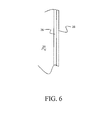
- FIGs. 5 and 6 A second embodiment is shown in FIGs. 5 and 6 .
- the fastener 10 incorporates a shank 12 with a threaded portion 14 on a first end and a head 16 on a second end.
- a lead-in portion 18 provides transition from the threaded portion 14 into the main body 20 of the shank 12.
- the threaded portion 14 and lead-in portion 18 are coated with a dry (and galvanically compatible) coating that is lubricious such as a BMS10-85 Phenolic based aluminum pigmented coating.
- the coating maybe applied by dip, spray or other standard organic coating techniques.
- the main body 20 is coated with a multiple layer metallic laminate.
- an adhesion layer 26 is deposited on at least the main body 20.
- a nickel strike is employed as the adhesion layer.
- a copper or iron strike may be employed and the adhesion layer could be applied by a vacuum deposition process instead of electrodeposition.
- a soft metal layer 28 is then deposited over the adhesion layer as shown in FIG. 6 .
- a tin-zinc-bismuth alloy is employed.
- tin-bismuth may be employed. In the former, the soft metal layer 28 is approximately 65% tin with approximately 32-33% zinc, the remainder bismuth.
- the tin-zinc alloy is a standard cadmium replacement coating that is known in the art.
- the soft metal layer is not as sacrificial, but could be wet installed to compensate.
- the bismuth helps with the prevention or retardation of tin pest, a low temperature transformation of tin into a brittle phase.
- solid additives could be added to the coating such as PTFE or boron nitride that aid in lubricity in stackups that contain CFRP.
- the lubricious coating on the threaded portion 14 and lead-in portion 18 of the fastener 10 allows initial insertion into the interference fit hole.
- the tin-zinc-bismuth is soft providing low shear resistance for continuing insertion of the main body 20 of the fastener into the interference fit hole.
- the tin-zinc-bismuth alloy is highly conductive and provides intimate electrical contact between the fastener and the hole surface.
- Alternative embodiments may employ alloys based on indium such as tin-indium or zinc-indium, which are soft and galvanically compatible with aluminum. Alloys such as tin-aluminum are possible via vacuum deposition or special plating solutions. Coatings that can be deposited by thermal spray processing such as aluminum-polyester or aluminum-boron nitride, may be employed in alternative embodiments without the use of an adhesion layer.
- either of the embodiments for the fastener 10 described above is inserted in a hole 30 in a joint incorporating a composite layer 32.
- one joined element is a metallic sub structure 34 such as a fuel tank wall adjacent the composite layer
- the present embodiments provide intimate contact between the fastener 10 and the interior surface of the hole 30 which extends through both the composite layer 32 and metallic sub structure 34.
- charge 36 attaching to the head 16 is conducted down the fastener 10, exposed fastener metal as in the peaks of the knurled main body and/or metal coating layers such as the nickel and tin-zinc-bismuth as represented by arrow 38 and from the fastener through the metal coating or exposed fastener metal to the metallic sub structure 34 as represented by arrow 40.
- the combination of the intimate conductive contact provided by either the exposed metal in the knurled peaks 22 or the soft metallic layer 28 allows a ready path for electrical energy transfer associated with large current densities up to 1.5 x 10 6 amp/in 2 required by the EME event and the interference fit prevents voids between the fastener and hole structure to suppress HPE formation. While the embodiments described herein are detailed relative to threaded fasteners, for other fastener systems, such as blind fasteners may be employed in alternative embodiments.
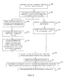
- the embodiments described herein may be employed for EME protection of an installed fastener by identifying a hole in a composite joint for installation of a fastener, step 802.
- a fastener diameter is established and a shank of the fastener configured for an interference fit in the hole, step 804.
- a roughened surface is formed on a body of the shank of the fastener such as by knurling, step 806.
- the fastener main body is coated with a lubricious coating, step 808. Polishing or burnishing the roughened surface removes the lubricious coating from peaks of the roughed surface but allows the coating to remain in valleys, step 810.
- an adhesion layer is deposited on the fastener, step 812, and a soft metal coating is deposited on the adhesion layer, step 814.
- a lubricious coating is deposited on a threaded portion and lead-in portion of the fastener, step 816.
- the fastener is then inserted into the hole, step 818, with the interference fit forming intimate conductive contact between the burnished peaks or soft metal coating and the surface of the hole, step 820, for electrical energy transfer, step 822, during an EME event.
Landscapes
- Engineering & Computer Science (AREA)
- General Engineering & Computer Science (AREA)
- Mechanical Engineering (AREA)
- Aviation & Aerospace Engineering (AREA)
- Connection Of Plates (AREA)
- Insertion Pins And Rivets (AREA)
- Electroplating Methods And Accessories (AREA)
Abstract
Description
- Embodiments of the disclosure relate generally to the field of fastener technologies for metal fasteners employed in composite structures and more particularly to a fastener with treatments of the shank to achieve increased lubricity with enhanced conductivity.
- Lightweight composite materials are employed for major structures in aircraft on a regular basis. Fiber composites provide a significant improvement in specific strength and stiffness over conventional metal alloys. Better specific strength and stiffness translates into weight savings, which translates into fuel savings and lower operating costs. Additionally, composites do not corrode like aluminum, and they are more resistant to fatigue. However, composite structures in these aircraft do not readily conduct away the extreme electrical currents and electromagnetic forces generated by lightning strikes.
- Structural fabrication using composites still requires fasteners for many assembly operations. Metallic fasteners are conductive creating electromagnetic effect (EME) design considerations for lightning strike and other EME issues. Fastener sparking modes must be designed for lightning conditions including Hot Particle Ejection (HPE) and arcing between an outer surface of the fastener head and other structure or fastener sleeves.
- When lightning strikes a Carbon Fiber Reinforced Polymer (CFRP) structure with metallic fasteners installed, a significant portion of the current may pass into nearby structures through the fasteners. When the electrical energy passes between two surfaces, contact resistance heating may break down the materials and generate hot gas (or plasma) in the hole, or in the space in-between a fastener and an associated internally threaded fastener such as a nut or frangible collar.
- Sleeved fasteners are currently employed in many composite structures as a combined solution to lightning protection and structural requirements providing an interference fit between the fastener and an associated hole in the composite joint. However, sleeves create additional weight in the structure, additional cost and time in assembly and may have additional failure modes.
- It is therefore desirable to provide a fastening system suitable for composite structural applications which overcomes both HPE and arcing while overcoming the drawbacks of the prior art fastener installation procedures providing an interference fit without requirements for sleeves.
- Embodiments disclosed herein provide a fastener system for composite structure providing electromagnetic energy protection having a shank with a threaded portion on a first end of the shank terminating in a lead-in portion. A head is present on a second end of the shank. The shank is adapted for intimate conductive contact with an inner surface of an interference fit hole.
- The embodiments provide a method for EME protection of fasteners in composite structures wherein a hole is identified in a composite joint for installation of a fastener. A fastener diameter is established and a shank of the fastener is configured for an interference fit in the hole. A lubricious coating is deposited on a threaded portion and lead-in portion of the fastener. The fastener is then inserted into the hole forming with the interference fit an intimate conductive contact between the shank and hole. Electrical energy may then be transferred during an EME event.
- The features, functions, and advantages that have been discussed can be achieved independently in various embodiments of the present disclosure or may be combined in yet other embodiments further details of which can be seen with reference to the following description and drawings.
- Further, the disclosure comprises embodiments according to the following clauses:
-
Clause 1. A joint for a composite structure comprising: a composite layer; a joined element adjacent the composite layer, said composite layer and joined element having a hole extending therethrough; a fastener received in the hole in an interference fit and having a shank; a threaded portion on a first end of the shank terminating in a lead-in portion and; a head on a second end of the shank; wherein the shank is adapted for intimate conductive contact with an inner surface of the hole. - Clause 2. The joint for a composite structure as defined in
clause 1 wherein the joined element is a metallic substructure. - Clause 3. The joint for a composite structure as defined in
clause 1 wherein the lead-in portion is configured to expand the inner surface of the interference fit hole without damaging the composite. - Clause 4. The joint for a composite structure as defined in
clause 1 wherein the shank has a roughened main body with peaks and valleys and further comprising a lubricious coating on the main body said coating polished for exposure of the peaks to maintain intimate conductive contact, while remaining present in the valleys for lubricious insertion into the interference fit hole. - Clause 5. The joint for a composite structure as defined in
clause 1 wherein a soft metal layer is deposited on the shank, said soft metal layer shearing for insertion in the interference fit hole while maintaining intimate conductive contact. -
-
FIG. 1 is a flow diagram of aircraft production and service methodology; -
FIG. 2 is a block diagram of an aircraft; -
FIG. 3 is a perspective view of a first embodiment with a knurled shank having an applied lubricious coating; -
FIG. 4 is a detailed section view of the knurling in the shank with the lubricious coating -
FIG. 5 is a perspective view of a second embodiment with a lubricious coating on the threads and lead-in portion of the shank with a soft metal coating on the shank between the lead-in portion and the head; -
FIG. 6 is a detailed section view of the coated main body of the shank; -
FIG. 7 is a partial section view of a fastener of either the first embodiment or the second embodiment installed with interference fit in a hole in a composite joint; and, -
FIG. 8 is a flow chart of a method for employing a fastener system with EME protection as defined in the embodiments. - The present embodiments provide intimate conductive contact by the fastener without the use of a sleeve for various EME protection requirements including lightning strike, High Intensity Radiated Fields, Fault Currents, Precipitation Static and Functional Grounding. An initial embodiment provides a fastener with a roughened shank surface onto which a dry lubricious coating is added. The roughened shank would then be polished to expose the fastener base metal in the peaks and keep the lubricious coating in the valleys. This ensures enough conductivity to maintaining a bond path for the high current densities of lightning energy as well as lubricity for interference fit installation. A second embodiment provides a fastener shank with two modifications. A lubricating coating is added to at least the lead-in geometry of the fastener with the remainder of the shank being coated with a soft metal. The lubricating coating on the fastener provides enough lubricity to ensure fastener can be installed into interference fit holes while the soft metal ensures good electrical bond while also aiding the installation. In both embodiments the interference fit installation may be accomplished without a sleeve and reduces voids between the fastener and structure preventing the ionization of air in voids to form HPE.
- Referring to the drawings, embodiments of the disclosure may be described in the context of an aircraft manufacturing and
service method 100 as shown inFIG. 1 and anaircraft 102 as shown inFIG. 2 . During pre-production,exemplary method 100 may include specification anddesign 104 of theaircraft 102 andmaterial procurement 106. During production, component andsubassembly manufacturing 108 andsystem integration 110 of theaircraft 102 takes place. Thereafter, theaircraft 102 may go through certification anddelivery 112 in order to be placed inservice 114. While in service by a customer, theaircraft 102 is scheduled for routine maintenance and service 116 (which may also include modification, reconfiguration, refurbishment, and so on). - Each of the processes of
method 100 may be performed or carried out by a system integrator, a third party, and/or an operator (e.g., a customer). For the purposes of this description, a system integrator may include without limitation any number of aircraft manufacturers and major-system subcontractors; a third party may include without limitation any number of venders, subcontractors, and suppliers; and an operator may be an airline, leasing company, military entity, service organization, and so on. - As shown in
FIG. 2 , theaircraft 102 produced byexemplary method 100 may include anairframe 118 with a plurality ofsystems 120 and aninterior 122. Examples of high-level systems 120 include one or more of apropulsion system 124, anelectrical system 126, ahydraulic system 128 and anenvironmental system 130. Any number of other systems may be included. Although an aerospace example is shown, the principles of the invention may be applied to other industries, such as the automotive industry. - Apparatus and methods embodied herein may be employed during any one or more of the stages of the production and
service method 100. For example, components or subassemblies corresponding toproduction process 108 may be fabricated or manufactured in a manner similar to components or subassemblies produced while theaircraft 102 is in service. Also, one or more apparatus embodiments, method embodiments, or a combination thereof may be utilized during the production stages 108 and 110, for example, by substantially expediting assembly of or reducing the cost of anaircraft 102. Similarly, one or more of apparatus embodiments, method embodiments, or a combination thereof may be utilized while theaircraft 102 is in service, for example and without limitation, to maintenance andservice 116. - The embodiments described herein provide a fastener system providing EME protection available for use in assembly requirements in the methods or systems of an aircraft as defined in
FIGs. 1 and 2 and described above or any similar structural assembly. - As shown in
FIG. 3 , a first embodiment of the fastener system incorporates afastener 10 having ashank 12 with a threadedportion 14 on a first end and ahead 16 on a second end. An anti-rotation feature such as a hex bore 17 may be included in the fastener for use during installation of a nut on the threadedportion 14. A lead-inportion 18 provides transition from the threadedportion 14 into themain body 20 of theshank 12. The lead-inportion 18 may incorporate arounded shoulder 19 or taper to transitionally engage the main body of the shank and inner surface of the hole in an interference fit. Themain body 20 incorporates a roughened surface which may be created by knurling or similar machining procedures. In exemplary embodiments, the peak-to-valley height should be between 0.0002 inch and 0.001 inch. A dry coating that is lubricious is added to the fastener including the knurling on the main body. For exemplary embodiments, the dry coating is "aluminum pigmented coating", which in the example embodiment is phenolic resin based (as the matrix), and contains lubricating pigments, typically aluminum flake or particle such as BMS10-85 Phenolic based aluminum pigmented coating. Corrosion prevention additives may also be employed. In alternative embodiments epoxy based coatings, and other solid film lubricants that are resin or ceramic based, with solid lubricant additives may be employed. The knurled shank is polished to remove coating fromknurl peaks 22 but retain the coating inknurl valleys 24 as shown inFIG. 4 . The lubricious surface area on the shank main body in the knurl valleys as well as the threaded portion and geometry of the lead-inportion 18 is configured to adapt thefastener 10 to be inserted in a hole in a composite structure with an interference fit to expand the inner surface of the hole without damaging the composite. However, the contact surface area of the burnished peaks of the knurled shank main body provide intimate electrical conductive contact between the fastener and the hole surface allowing electrical energy transfer with large current densities as will be described in greater detail subsequently. - A second embodiment is shown in
FIGs. 5 and6 . As in the first embodiment, thefastener 10 incorporates ashank 12 with a threadedportion 14 on a first end and ahead 16 on a second end. A lead-inportion 18 provides transition from the threadedportion 14 into themain body 20 of theshank 12. The threadedportion 14 and lead-inportion 18 are coated with a dry (and galvanically compatible) coating that is lubricious such as a BMS10-85 Phenolic based aluminum pigmented coating. The coating maybe applied by dip, spray or other standard organic coating techniques. Themain body 20 is coated with a multiple layer metallic laminate. For exemplary embodiments with titanium fasteners, anadhesion layer 26 is deposited on at least themain body 20. In an exemplary embodiment a nickel strike is employed as the adhesion layer. In alternative embodiments, a copper or iron strike may be employed and the adhesion layer could be applied by a vacuum deposition process instead of electrodeposition. Asoft metal layer 28 is then deposited over the adhesion layer as shown inFIG. 6 . For exemplary embodiments a tin-zinc-bismuth alloy is employed. In alternative embodiments, tin-bismuth may be employed. In the former, thesoft metal layer 28 is approximately 65% tin with approximately 32-33% zinc, the remainder bismuth. The tin-zinc alloy is a standard cadmium replacement coating that is known in the art. In the latter, the soft metal layer is not as sacrificial, but could be wet installed to compensate. For tin-based coatings, the bismuth helps with the prevention or retardation of tin pest, a low temperature transformation of tin into a brittle phase. Also, solid additives could be added to the coating such as PTFE or boron nitride that aid in lubricity in stackups that contain CFRP. The lubricious coating on the threadedportion 14 and lead-inportion 18 of thefastener 10 allows initial insertion into the interference fit hole. The tin-zinc-bismuth is soft providing low shear resistance for continuing insertion of themain body 20 of the fastener into the interference fit hole. However, the tin-zinc-bismuth alloy is highly conductive and provides intimate electrical contact between the fastener and the hole surface. Alternative embodiments may employ alloys based on indium such as tin-indium or zinc-indium, which are soft and galvanically compatible with aluminum. Alloys such as tin-aluminum are possible via vacuum deposition or special plating solutions. Coatings that can be deposited by thermal spray processing such as aluminum-polyester or aluminum-boron nitride, may be employed in alternative embodiments without the use of an adhesion layer. - As shown in
FIG. 7 , either of the embodiments for thefastener 10 described above is inserted in ahole 30 in a joint incorporating a composite layer 32. In particularly advantageous joint configurations where one joined element is a metallic sub structure 34 such as a fuel tank wall adjacent the composite layer, the present embodiments provide intimate contact between thefastener 10 and the interior surface of thehole 30 which extends through both the composite layer 32 and metallic sub structure 34. In a lightning strike or other EME event which may have large current densities (resulting from currents of 100 -200 KA peak in lightning strike conditions),charge 36 attaching to thehead 16 is conducted down thefastener 10, exposed fastener metal as in the peaks of the knurled main body and/or metal coating layers such as the nickel and tin-zinc-bismuth as represented byarrow 38 and from the fastener through the metal coating or exposed fastener metal to the metallic sub structure 34 as represented byarrow 40. The combination of the intimate conductive contact provided by either the exposed metal in the knurled peaks 22 or the softmetallic layer 28 allows a ready path for electrical energy transfer associated with large current densities up to 1.5 x 10⁶ amp/in2 required by the EME event and the interference fit prevents voids between the fastener and hole structure to suppress HPE formation. While the embodiments described herein are detailed relative to threaded fasteners, for other fastener systems, such as blind fasteners may be employed in alternative embodiments. - As shown in
FIG. 8 the embodiments described herein may be employed for EME protection of an installed fastener by identifying a hole in a composite joint for installation of a fastener,step 802. A fastener diameter is established and a shank of the fastener configured for an interference fit in the hole,step 804. A roughened surface is formed on a body of the shank of the fastener such as by knurling,step 806. The fastener main body is coated with a lubricious coating,step 808. Polishing or burnishing the roughened surface removes the lubricious coating from peaks of the roughed surface but allows the coating to remain in valleys,step 810. Alternatively an adhesion layer is deposited on the fastener,step 812, and a soft metal coating is deposited on the adhesion layer,step 814. A lubricious coating is deposited on a threaded portion and lead-in portion of the fastener,step 816. The fastener is then inserted into the hole, step 818, with the interference fit forming intimate conductive contact between the burnished peaks or soft metal coating and the surface of the hole, step 820, for electrical energy transfer, step 822, during an EME event. - Having now described various embodiments of the disclosure in detail as required by the patent statutes, those skilled in the art will recognize modifications and substitutions to the specific embodiments disclosed herein. Such modifications are within the scope and intent of the present disclosure as defined in the following claims.
Claims (15)
- A fastener system (10) for composite structure comprising;
a shank (12);
a threaded portion (14) on a first end of the shank (12) terminating in a lead-in portion (18) and;
a head (16) on a second end of the shank (12);
wherein the shank (12) is adapted for intimate conductive contact with an inner surface of an interference fit hole (30) in a composite (32). - The fastener system as defined in claim 1 wherein the lead-in portion (18) is configured to expand the inner surface of the interference fit hole without damaging the composite.
- The fastener system as defined in claim 2 wherein the shank (12) is in intimate conductive contact with the inner surface of the hole (30) to conduct large current densities.
- The fastener system as defined in any preceding claim wherein the threaded portion (14) and the lead in portion (18) are coated in dry lubricant.
- The fastener system as defined in any preceding claim wherein the shank (12) has a roughened main body (20) with peaks (22) and valleys (24) and further comprising a lubricious coating on the main body said coating polished for exposure of the peaks (22) to maintain intimate conductive contact, while remaining present in the valleys (24) for lubricious insertion into the interference fit hole (30).
- The fastener system as defined in claim 5 wherein the lubricious coating is one of a phenolic resin base containing lubricating pigments, epoxy based coatings, and other solid film lubricants that are resin or ceramic based, with solid lubricant additives.
- The fastener system as defined in any preceding claim wherein a soft metal layer (28) is deposited on the shank (12), said soft metal layer (28) shearing for insertion in the interference fit hole (30) while maintaining intimate conductive contact.
- The fastener system as defined in claim 7 wherein an adhesion layer (26) is deposited on at least the main body portion (20) and the soft metal layer (28) is plated over the adhesion layer (26).
- The fastener system as defined in claim 7 or 8 wherein the soft metal layer (28) comprises one of tin-zinc-bismuth, tin-bismuth, tin-indium, zinc-indium, tin-aluminum, aluminum-polyester or aluminum-boron nitride.
- The fastener system as defined in any of claims 8 to 9 wherein the adhesion layer (26) comprises one of a nickel strike, a copper strike or an iron strike.
- A method for EME protection of fasteners (10) in composite structures (32) comprising:identifying a hole (30) in a composite joint for installation of a fastener (10);establishing a fastener diameter;configuring a shank (12) of the fastener for an interference fit in the hole (30);depositing a lubricious coating on a threaded portion (14) and lead-in portion (18) of the fastener (10);inserting the fastener (10) into the hole (30);forming with the interference fit an intimate conductive contact between the shank (12) and hole (30); and,transferring electrical energy during an EME event.
- The method of claim 11 wherein the step of configuring comprises:forming a roughened surface is formed on a main body (20) of the shank (12) of the fastener;coating the fastener main body (20) with a lubricious coating;polishing the roughened surface to remove the lubricious coating from peaks (22) of the roughed surface but allowing the coating to remain in valleys.
- The method of claim 11or 12 wherein the step of configuring comprises depositing a soft metal coating (28) on the shank (12).
- The method of clam 13 wherein the step of configuring further comprises depositing an adhesive layer (26) on the fastener (10); and depositing the soft metal coating (28) on the adhesive layer or strike.
- The method of claim 14 wherein the adhesive layer (26) comprises a nickel strike, a copper strike or an iron strike.
Applications Claiming Priority (1)
| Application Number | Priority Date | Filing Date | Title |
|---|---|---|---|
| US14/286,612 US9908637B2 (en) | 2014-05-23 | 2014-05-23 | Modified shank fasteners for electromagnetic effect (EME) technology |
Publications (2)
| Publication Number | Publication Date |
|---|---|
| EP2947015A1 true EP2947015A1 (en) | 2015-11-25 |
| EP2947015B1 EP2947015B1 (en) | 2017-04-12 |
Family
ID=53002502
Family Applications (1)
| Application Number | Title | Priority Date | Filing Date |
|---|---|---|---|
| EP15163457.3A Active EP2947015B1 (en) | 2014-05-23 | 2015-04-14 | Modified shank fasteners for electromagnetic effect (eme) technology |
Country Status (7)
| Country | Link |
|---|---|
| US (1) | US9908637B2 (en) |
| EP (1) | EP2947015B1 (en) |
| JP (1) | JP6434364B2 (en) |
| KR (1) | KR102285190B1 (en) |
| CN (1) | CN105090200B (en) |
| AU (1) | AU2015200623B2 (en) |
| CA (1) | CA2880378C (en) |
Cited By (5)
| Publication number | Priority date | Publication date | Assignee | Title |
|---|---|---|---|---|
| EP3239542A1 (en) * | 2016-04-28 | 2017-11-01 | The Boeing Company | Expandable resin filled fastener, fastener system, and method for composite structures |
| EP3321523A1 (en) * | 2016-11-11 | 2018-05-16 | The Boeing Company | Fasteners having enhanced electrical energy dispersion properties |
| NL2017955B1 (en) * | 2016-11-11 | 2018-06-19 | Boeing Co | Fasteners having enhanced electrical energy dispersion properties |
| EP3434805A1 (en) * | 2017-07-28 | 2019-01-30 | The Boeing Company | Process for adhering solid lubricant to surface of interference fit fastener |
| EP3511579A1 (en) * | 2018-01-15 | 2019-07-17 | Subaru Corporation | Fastening structure |
Families Citing this family (13)
| Publication number | Priority date | Publication date | Assignee | Title |
|---|---|---|---|---|
| US10878139B2 (en) * | 2015-07-27 | 2020-12-29 | The Boeing Company | Composite joint optimization |
| US10711814B2 (en) * | 2017-02-20 | 2020-07-14 | The Boeing Company | Tapered lead-in for interference fit fasteners |
| EP3399197A1 (en) * | 2017-05-04 | 2018-11-07 | Fairchild Fasteners Europe - VSD GmbH | Fastener for attaching together workpieces having aligned holes therethrough |
| US10808749B2 (en) * | 2017-08-25 | 2020-10-20 | The Boeing Company | Method and systems for inserting a coated fastener in an assembly |
| EP3701893B1 (en) * | 2017-12-06 | 2022-12-21 | Stryker European Operations Holdings LLC | Orthopedic locking screw |
| US10774863B2 (en) * | 2018-06-18 | 2020-09-15 | The Boeing Company | Blind fastener system with electromagnetic effects-protective coating |
| TWM580636U (en) * | 2018-11-16 | 2019-07-11 | 台灣耐落螺絲工業股份有限公司 | Fastener structure with integrated conductive and anti-loose/leak-proof |
| US11137014B2 (en) * | 2019-01-08 | 2021-10-05 | The Boeing Company | Conductive fastening system and method for improved EME performance |
| US11396900B2 (en) * | 2019-05-10 | 2022-07-26 | The Boeing Company | Fastener and methods of manufacturing and use |
| FR3100821B1 (en) * | 2019-09-16 | 2021-09-24 | Lisi Aerospace | Titanium alloy fastener and method of manufacture |
| US11148188B2 (en) | 2019-10-28 | 2021-10-19 | The Boeing Company | Tool and associated method for installing a blind fastener |
| US11649845B2 (en) | 2019-12-16 | 2023-05-16 | The Boeing Company | Mechanical fastener system for electromagnetic effect (EME) protection |
| US20230286637A1 (en) * | 2022-03-09 | 2023-09-14 | The Boeing Company | Vehicle window assembly |
Citations (9)
| Publication number | Priority date | Publication date | Assignee | Title |
|---|---|---|---|---|
| US3983304A (en) * | 1973-09-19 | 1976-09-28 | Hi-Shear Corporation | Fastener with protective metal-organic base coating |
| GB2212580A (en) * | 1987-11-14 | 1989-07-26 | British Aerospace | Anti-lightning fastener |
| FR2672091A1 (en) * | 1991-01-30 | 1992-07-31 | Sigre Sa | Assembly screw |
| EP0685389A1 (en) * | 1994-06-02 | 1995-12-06 | British Aerospace Public Limited Company | Method of fastening composite aircraft skins |
| US20030219328A1 (en) * | 2002-05-23 | 2003-11-27 | Dennis Schultz | Light weight fastener for use on interference fits in automation |
| WO2011050040A1 (en) * | 2009-10-22 | 2011-04-28 | Alcoa Inc. | Enhanced conductivity sleeved fastener and method for making same |
| EP2406336A1 (en) * | 2009-03-13 | 2012-01-18 | Hi-Shear Corporation | Anti-corrosion and low friction coating |
| US20140055906A1 (en) * | 2012-03-29 | 2014-02-27 | The Boeing Company | Fastener systems that provide eme protection |
| US20140130335A1 (en) * | 2012-11-11 | 2014-05-15 | The Boeing Company | Structural blind fastener and method of installation |
Family Cites Families (36)
| Publication number | Priority date | Publication date | Assignee | Title |
|---|---|---|---|---|
| US3396996A (en) * | 1967-01-12 | 1968-08-13 | Leona H Dounis | Self-sealing bolt assembly |
| US3630253A (en) * | 1969-10-22 | 1971-12-28 | Lamson & Sessions Co | Interference fastener |
| JPS47558U (en) * | 1971-01-18 | 1972-08-03 | ||
| US4074011A (en) * | 1974-04-25 | 1978-02-14 | Nippon Steel Corporation | Topcoated phosphated bolts, nuts and washers |
| US4054045A (en) * | 1975-01-17 | 1977-10-18 | King John O Jun | Two-piece mandrel assembly for deforming |
| US3962775A (en) * | 1975-01-17 | 1976-06-15 | King John O Jun | Method of forming a joint using a guide fastener |
| US4281044A (en) * | 1977-10-21 | 1981-07-28 | Rogers Corporation | Adhesion of phenolics to copper |
| IT1146785B (en) | 1981-05-20 | 1986-11-19 | Danieli Off Mecc | PARKING DEVICE FALSA BAR UPstream of the EXTRACTION AND STRAIGHTENING GROUP |
| JPS6056814U (en) * | 1983-09-27 | 1985-04-20 | 株式会社小松製作所 | centering bolt |
| JPS6165425U (en) * | 1984-09-28 | 1986-05-06 | ||
| US4755904A (en) * | 1986-06-06 | 1988-07-05 | The Boeing Company | Lightning protection system for conductive composite material structure |
| FR2647166B1 (en) * | 1989-05-19 | 1991-07-12 | Garonne Ets Auriol & Cie | BLIND RIVETING MEMBER, ASSEMBLY METHOD AND ASSEMBLIES OBTAINED |
| US5603592A (en) * | 1994-10-03 | 1997-02-18 | Huck International, Inc. | High strength blind bolt with uniform high clamp over an extended grip range |
| JP3698830B2 (en) * | 1995-09-11 | 2005-09-21 | 光洋精工株式会社 | Lead screw and method for forming lubricant film on lead screw |
| JP3373709B2 (en) * | 1995-10-27 | 2003-02-04 | 大豊工業株式会社 | Copper-based sliding bearing materials and sliding bearings for internal combustion engines |
| US5685680A (en) * | 1996-05-02 | 1997-11-11 | Nylok Fastener Corporation | Coated threaded fasteners with coating-free crests |
| DE19916860A1 (en) * | 1998-04-28 | 1999-11-04 | Mcgard Inc | Fastening element for fitting wheel to motor vehicle |
| IT1305152B1 (en) * | 1998-11-02 | 2001-04-10 | Skf Ind Spa | PRISONER SCREWS OF THE PERFECT TYPE FOR THE CONNECTION OF A WHEEL AND A BRAKING ELEMENT TO THE HUB OF THE WHEEL OF A VEHICLE |
| US6129996A (en) * | 1999-08-16 | 2000-10-10 | Ford Motor Company | Conversion coatings of tin with cobalt and bismuth for aluminum sliding surfaces |
| JP2001056010A (en) * | 1999-08-16 | 2001-02-27 | Sannohashi:Kk | Bolt |
| US7192639B2 (en) * | 2004-01-14 | 2007-03-20 | Hi-Shear Corporation | Chromate free corrosion resistant coating |
| US7293947B2 (en) * | 2004-04-09 | 2007-11-13 | Phillips Screw Company | Screw having a knurled portion |
| JP4524483B2 (en) * | 2004-04-28 | 2010-08-18 | 石原薬品株式会社 | Tin or tin alloy plating method |
| JP4851121B2 (en) * | 2005-06-13 | 2012-01-11 | 本田技研工業株式会社 | Screw and screw fastening structure |
| US7755876B2 (en) | 2005-07-01 | 2010-07-13 | The Boeing Company | Fastening assembly including washer for sealing the assembly for lightning strike protection in composite structures |
| US7842403B2 (en) * | 2006-02-23 | 2010-11-30 | Atotech Deutschland Gmbh | Antifriction coatings, methods of producing such coatings and articles including such coatings |
| US7695226B2 (en) * | 2006-09-21 | 2010-04-13 | Alcoa Global Fasteners, Inc. | High performance sleeved interference fasteners for composite applications |
| US7599164B2 (en) | 2006-12-07 | 2009-10-06 | The Boeing Company | Lightning protection system for aircraft composite structure |
| US20110036621A1 (en) * | 2007-06-29 | 2011-02-17 | The Furukawa Electric Co., Ltd. | Metal material, method for producing the same, and electrical/electronic component using the same |
| WO2010115085A1 (en) | 2009-04-03 | 2010-10-07 | Alcoa Inc. | Conductive solid film material |
| US8322958B2 (en) * | 2009-04-03 | 2012-12-04 | Alcoa Inc. | Fasteners with conforming sleeves |
| JP5619446B2 (en) * | 2010-03-23 | 2014-11-05 | 三菱重工業株式会社 | Cap, fastening structure using the cap, and aircraft having the fastening structure |
| US9057397B2 (en) * | 2010-09-22 | 2015-06-16 | Mcgard Llc | Chrome-plated fastener with organic coating |
| US20120201999A1 (en) * | 2011-02-08 | 2012-08-09 | Woods Mark A | Methods and apparatus for mechanically joining metal components and composite components |
| RU2592958C2 (en) * | 2013-11-06 | 2016-07-27 | Зе Боинг Компани | Fastening systems, ensuring protection against electromagnetic effects |
| JP6544641B2 (en) * | 2015-10-26 | 2019-07-17 | 株式会社NejiLaw | Fastening device |
-
2014
- 2014-05-23 US US14/286,612 patent/US9908637B2/en active Active
-
2015
- 2015-01-29 CA CA2880378A patent/CA2880378C/en active Active
- 2015-02-09 AU AU2015200623A patent/AU2015200623B2/en active Active
- 2015-02-27 CN CN201510090113.XA patent/CN105090200B/en active Active
- 2015-04-10 KR KR1020150050858A patent/KR102285190B1/en active IP Right Grant
- 2015-04-14 EP EP15163457.3A patent/EP2947015B1/en active Active
- 2015-05-12 JP JP2015097035A patent/JP6434364B2/en active Active
Patent Citations (9)
| Publication number | Priority date | Publication date | Assignee | Title |
|---|---|---|---|---|
| US3983304A (en) * | 1973-09-19 | 1976-09-28 | Hi-Shear Corporation | Fastener with protective metal-organic base coating |
| GB2212580A (en) * | 1987-11-14 | 1989-07-26 | British Aerospace | Anti-lightning fastener |
| FR2672091A1 (en) * | 1991-01-30 | 1992-07-31 | Sigre Sa | Assembly screw |
| EP0685389A1 (en) * | 1994-06-02 | 1995-12-06 | British Aerospace Public Limited Company | Method of fastening composite aircraft skins |
| US20030219328A1 (en) * | 2002-05-23 | 2003-11-27 | Dennis Schultz | Light weight fastener for use on interference fits in automation |
| EP2406336A1 (en) * | 2009-03-13 | 2012-01-18 | Hi-Shear Corporation | Anti-corrosion and low friction coating |
| WO2011050040A1 (en) * | 2009-10-22 | 2011-04-28 | Alcoa Inc. | Enhanced conductivity sleeved fastener and method for making same |
| US20140055906A1 (en) * | 2012-03-29 | 2014-02-27 | The Boeing Company | Fastener systems that provide eme protection |
| US20140130335A1 (en) * | 2012-11-11 | 2014-05-15 | The Boeing Company | Structural blind fastener and method of installation |
Cited By (16)
| Publication number | Priority date | Publication date | Assignee | Title |
|---|---|---|---|---|
| US10087975B2 (en) | 2016-04-28 | 2018-10-02 | The Boeing Company | Expandable, resin filled fastener, fastener system, and method for composite structures |
| CN107339304A (en) * | 2016-04-28 | 2017-11-10 | 波音公司 | Expandable resin filling fastener, closure system and the method for composite construction |
| EP3239542A1 (en) * | 2016-04-28 | 2017-11-01 | The Boeing Company | Expandable resin filled fastener, fastener system, and method for composite structures |
| EP3505782A1 (en) * | 2016-11-11 | 2019-07-03 | The Boeing Company | Fasteners having enhanced electrical energy dispersion properties |
| NL2017955B1 (en) * | 2016-11-11 | 2018-06-19 | Boeing Co | Fasteners having enhanced electrical energy dispersion properties |
| CN108071646A (en) * | 2016-11-11 | 2018-05-25 | 波音公司 | The fastener of electric energy dispersion property with enhancing |
| RU2685737C2 (en) * | 2016-11-11 | 2019-04-23 | Зе Боинг Компани | Fasteners with improved electric energy scattering properties |
| EP3321523A1 (en) * | 2016-11-11 | 2018-05-16 | The Boeing Company | Fasteners having enhanced electrical energy dispersion properties |
| EP3550161A1 (en) | 2016-11-11 | 2019-10-09 | The Boeing Company | Fasteners having enhanced electrical energy dispersion properties |
| US10495130B2 (en) | 2016-11-11 | 2019-12-03 | The Boeing Company | Fasteners having enhanced electrical energy dispersion properties |
| EP3604833A1 (en) | 2016-11-11 | 2020-02-05 | The Boeing Company | Fasteners having enhanced electrical energy dispersion properties |
| CN108071646B (en) * | 2016-11-11 | 2020-05-15 | 波音公司 | Fastener with enhanced electrical energy dissipation properties |
| US11293474B2 (en) | 2016-11-11 | 2022-04-05 | The Boeing Company | Fasteners having enhanced electrical energy dispersion properties |
| EP3434805A1 (en) * | 2017-07-28 | 2019-01-30 | The Boeing Company | Process for adhering solid lubricant to surface of interference fit fastener |
| EP3511579A1 (en) * | 2018-01-15 | 2019-07-17 | Subaru Corporation | Fastening structure |
| US11873113B2 (en) | 2018-01-15 | 2024-01-16 | Subaru Corporation | Fastening structure |
Also Published As
| Publication number | Publication date |
|---|---|
| US9908637B2 (en) | 2018-03-06 |
| EP2947015B1 (en) | 2017-04-12 |
| KR102285190B1 (en) | 2021-08-03 |
| CA2880378C (en) | 2017-06-06 |
| KR20150135068A (en) | 2015-12-02 |
| AU2015200623B2 (en) | 2018-04-26 |
| CA2880378A1 (en) | 2015-11-23 |
| CN105090200A (en) | 2015-11-25 |
| US20150337885A1 (en) | 2015-11-26 |
| JP6434364B2 (en) | 2018-12-05 |
| CN105090200B (en) | 2019-03-19 |
| AU2015200623A1 (en) | 2015-12-10 |
| JP2015224789A (en) | 2015-12-14 |
Similar Documents
| Publication | Publication Date | Title |
|---|---|---|
| CA2880378C (en) | Modified shank fasteners for electromagnetic effect (eme) technology | |
| EP2414236B2 (en) | Fasteners with conforming sleeves | |
| US10014593B2 (en) | Conductive sleeved fastener assembly | |
| EP3194798B1 (en) | Fasteners with coated and textured pin members | |
| US11137014B2 (en) | Conductive fastening system and method for improved EME performance | |
| US9702396B2 (en) | Fasteners with dual skin depth washers | |
| US20180195549A1 (en) | Coated fasteners with conforming seals | |
| US20160068275A1 (en) | Locking member with sealing insert and channel | |
| EP3848593B1 (en) | Conductively coated fastening systems for full size determinant assembly (fsda) | |
| EP3296365A1 (en) | Method for promoting electrical conduction between metallic components and composite materials | |
| EP3341621B1 (en) | Coated fasteners with conforming seals | |
| US11649845B2 (en) | Mechanical fastener system for electromagnetic effect (EME) protection | |
| CA2954898C (en) | Coated fasteners with conforming seals |
Legal Events
| Date | Code | Title | Description |
|---|---|---|---|
| PUAI | Public reference made under article 153(3) epc to a published international application that has entered the european phase |
Free format text: ORIGINAL CODE: 0009012 |
|
| AK | Designated contracting states |
Kind code of ref document: A1 Designated state(s): AL AT BE BG CH CY CZ DE DK EE ES FI FR GB GR HR HU IE IS IT LI LT LU LV MC MK MT NL NO PL PT RO RS SE SI SK SM TR |
|
| AX | Request for extension of the european patent |
Extension state: BA ME |
|
| 17P | Request for examination filed |
Effective date: 20160414 |
|
| RBV | Designated contracting states (corrected) |
Designated state(s): AL AT BE BG CH CY CZ DE DK EE ES FI FR GB GR HR HU IE IS IT LI LT LU LV MC MK MT NL NO PL PT RO RS SE SI SK SM TR |
|
| GRAP | Despatch of communication of intention to grant a patent |
Free format text: ORIGINAL CODE: EPIDOSNIGR1 |
|
| INTG | Intention to grant announced |
Effective date: 20161122 |
|
| GRAS | Grant fee paid |
Free format text: ORIGINAL CODE: EPIDOSNIGR3 |
|
| GRAA | (expected) grant |
Free format text: ORIGINAL CODE: 0009210 |
|
| AK | Designated contracting states |
Kind code of ref document: B1 Designated state(s): AL AT BE BG CH CY CZ DE DK EE ES FI FR GB GR HR HU IE IS IT LI LT LU LV MC MK MT NL NO PL PT RO RS SE SI SK SM TR |
|
| REG | Reference to a national code |
Ref country code: GB Ref legal event code: FG4D |
|
| REG | Reference to a national code |
Ref country code: CH Ref legal event code: EP |
|
| REG | Reference to a national code |
Ref country code: FR Ref legal event code: PLFP Year of fee payment: 3 |
|
| REG | Reference to a national code |
Ref country code: IE Ref legal event code: FG4D |
|
| REG | Reference to a national code |
Ref country code: AT Ref legal event code: REF Ref document number: 883585 Country of ref document: AT Kind code of ref document: T Effective date: 20170515 |
|
| REG | Reference to a national code |
Ref country code: DE Ref legal event code: R096 Ref document number: 602015002171 Country of ref document: DE |
|
| REG | Reference to a national code |
Ref country code: NL Ref legal event code: MP Effective date: 20170412 |
|
| REG | Reference to a national code |
Ref country code: LT Ref legal event code: MG4D |
|
| REG | Reference to a national code |
Ref country code: AT Ref legal event code: MK05 Ref document number: 883585 Country of ref document: AT Kind code of ref document: T Effective date: 20170412 |
|
| PG25 | Lapsed in a contracting state [announced via postgrant information from national office to epo] |
Ref country code: NL Free format text: LAPSE BECAUSE OF FAILURE TO SUBMIT A TRANSLATION OF THE DESCRIPTION OR TO PAY THE FEE WITHIN THE PRESCRIBED TIME-LIMIT Effective date: 20170412 |
|
| PG25 | Lapsed in a contracting state [announced via postgrant information from national office to epo] |
Ref country code: AT Free format text: LAPSE BECAUSE OF FAILURE TO SUBMIT A TRANSLATION OF THE DESCRIPTION OR TO PAY THE FEE WITHIN THE PRESCRIBED TIME-LIMIT Effective date: 20170412 Ref country code: NO Free format text: LAPSE BECAUSE OF FAILURE TO SUBMIT A TRANSLATION OF THE DESCRIPTION OR TO PAY THE FEE WITHIN THE PRESCRIBED TIME-LIMIT Effective date: 20170712 Ref country code: LT Free format text: LAPSE BECAUSE OF FAILURE TO SUBMIT A TRANSLATION OF THE DESCRIPTION OR TO PAY THE FEE WITHIN THE PRESCRIBED TIME-LIMIT Effective date: 20170412 Ref country code: HR Free format text: LAPSE BECAUSE OF FAILURE TO SUBMIT A TRANSLATION OF THE DESCRIPTION OR TO PAY THE FEE WITHIN THE PRESCRIBED TIME-LIMIT Effective date: 20170412 Ref country code: ES Free format text: LAPSE BECAUSE OF FAILURE TO SUBMIT A TRANSLATION OF THE DESCRIPTION OR TO PAY THE FEE WITHIN THE PRESCRIBED TIME-LIMIT Effective date: 20170412 Ref country code: GR Free format text: LAPSE BECAUSE OF FAILURE TO SUBMIT A TRANSLATION OF THE DESCRIPTION OR TO PAY THE FEE WITHIN THE PRESCRIBED TIME-LIMIT Effective date: 20170713 Ref country code: FI Free format text: LAPSE BECAUSE OF FAILURE TO SUBMIT A TRANSLATION OF THE DESCRIPTION OR TO PAY THE FEE WITHIN THE PRESCRIBED TIME-LIMIT Effective date: 20170412 |
|
| PG25 | Lapsed in a contracting state [announced via postgrant information from national office to epo] |
Ref country code: SE Free format text: LAPSE BECAUSE OF FAILURE TO SUBMIT A TRANSLATION OF THE DESCRIPTION OR TO PAY THE FEE WITHIN THE PRESCRIBED TIME-LIMIT Effective date: 20170412 Ref country code: BG Free format text: LAPSE BECAUSE OF FAILURE TO SUBMIT A TRANSLATION OF THE DESCRIPTION OR TO PAY THE FEE WITHIN THE PRESCRIBED TIME-LIMIT Effective date: 20170712 Ref country code: LV Free format text: LAPSE BECAUSE OF FAILURE TO SUBMIT A TRANSLATION OF THE DESCRIPTION OR TO PAY THE FEE WITHIN THE PRESCRIBED TIME-LIMIT Effective date: 20170412 Ref country code: IS Free format text: LAPSE BECAUSE OF FAILURE TO SUBMIT A TRANSLATION OF THE DESCRIPTION OR TO PAY THE FEE WITHIN THE PRESCRIBED TIME-LIMIT Effective date: 20170812 Ref country code: RS Free format text: LAPSE BECAUSE OF FAILURE TO SUBMIT A TRANSLATION OF THE DESCRIPTION OR TO PAY THE FEE WITHIN THE PRESCRIBED TIME-LIMIT Effective date: 20170412 Ref country code: PL Free format text: LAPSE BECAUSE OF FAILURE TO SUBMIT A TRANSLATION OF THE DESCRIPTION OR TO PAY THE FEE WITHIN THE PRESCRIBED TIME-LIMIT Effective date: 20170412 |
|
| REG | Reference to a national code |
Ref country code: DE Ref legal event code: R097 Ref document number: 602015002171 Country of ref document: DE |
|
| REG | Reference to a national code |
Ref country code: IE Ref legal event code: MM4A |
|
| PG25 | Lapsed in a contracting state [announced via postgrant information from national office to epo] |
Ref country code: RO Free format text: LAPSE BECAUSE OF FAILURE TO SUBMIT A TRANSLATION OF THE DESCRIPTION OR TO PAY THE FEE WITHIN THE PRESCRIBED TIME-LIMIT Effective date: 20170412 Ref country code: CZ Free format text: LAPSE BECAUSE OF FAILURE TO SUBMIT A TRANSLATION OF THE DESCRIPTION OR TO PAY THE FEE WITHIN THE PRESCRIBED TIME-LIMIT Effective date: 20170412 Ref country code: MC Free format text: LAPSE BECAUSE OF FAILURE TO SUBMIT A TRANSLATION OF THE DESCRIPTION OR TO PAY THE FEE WITHIN THE PRESCRIBED TIME-LIMIT Effective date: 20170412 Ref country code: EE Free format text: LAPSE BECAUSE OF FAILURE TO SUBMIT A TRANSLATION OF THE DESCRIPTION OR TO PAY THE FEE WITHIN THE PRESCRIBED TIME-LIMIT Effective date: 20170412 Ref country code: DK Free format text: LAPSE BECAUSE OF FAILURE TO SUBMIT A TRANSLATION OF THE DESCRIPTION OR TO PAY THE FEE WITHIN THE PRESCRIBED TIME-LIMIT Effective date: 20170412 Ref country code: SK Free format text: LAPSE BECAUSE OF FAILURE TO SUBMIT A TRANSLATION OF THE DESCRIPTION OR TO PAY THE FEE WITHIN THE PRESCRIBED TIME-LIMIT Effective date: 20170412 |
|
| PLBE | No opposition filed within time limit |
Free format text: ORIGINAL CODE: 0009261 |
|
| STAA | Information on the status of an ep patent application or granted ep patent |
Free format text: STATUS: NO OPPOSITION FILED WITHIN TIME LIMIT |
|
| PG25 | Lapsed in a contracting state [announced via postgrant information from national office to epo] |
Ref country code: LU Free format text: LAPSE BECAUSE OF NON-PAYMENT OF DUE FEES Effective date: 20170414 Ref country code: SM Free format text: LAPSE BECAUSE OF FAILURE TO SUBMIT A TRANSLATION OF THE DESCRIPTION OR TO PAY THE FEE WITHIN THE PRESCRIBED TIME-LIMIT Effective date: 20170412 Ref country code: IT Free format text: LAPSE BECAUSE OF FAILURE TO SUBMIT A TRANSLATION OF THE DESCRIPTION OR TO PAY THE FEE WITHIN THE PRESCRIBED TIME-LIMIT Effective date: 20170412 |
|
| 26N | No opposition filed |
Effective date: 20180115 |
|
| REG | Reference to a national code |
Ref country code: BE Ref legal event code: MM Effective date: 20170430 |
|
| REG | Reference to a national code |
Ref country code: FR Ref legal event code: PLFP Year of fee payment: 4 |
|
| PG25 | Lapsed in a contracting state [announced via postgrant information from national office to epo] |
Ref country code: IE Free format text: LAPSE BECAUSE OF NON-PAYMENT OF DUE FEES Effective date: 20170414 |
|
| PG25 | Lapsed in a contracting state [announced via postgrant information from national office to epo] |
Ref country code: SI Free format text: LAPSE BECAUSE OF FAILURE TO SUBMIT A TRANSLATION OF THE DESCRIPTION OR TO PAY THE FEE WITHIN THE PRESCRIBED TIME-LIMIT Effective date: 20170412 Ref country code: BE Free format text: LAPSE BECAUSE OF NON-PAYMENT OF DUE FEES Effective date: 20170430 |
|
| PG25 | Lapsed in a contracting state [announced via postgrant information from national office to epo] |
Ref country code: MT Free format text: LAPSE BECAUSE OF NON-PAYMENT OF DUE FEES Effective date: 20170414 |
|
| REG | Reference to a national code |
Ref country code: CH Ref legal event code: PL |
|
| PG25 | Lapsed in a contracting state [announced via postgrant information from national office to epo] |
Ref country code: LI Free format text: LAPSE BECAUSE OF NON-PAYMENT OF DUE FEES Effective date: 20180430 Ref country code: CH Free format text: LAPSE BECAUSE OF NON-PAYMENT OF DUE FEES Effective date: 20180430 |
|
| PG25 | Lapsed in a contracting state [announced via postgrant information from national office to epo] |
Ref country code: HU Free format text: LAPSE BECAUSE OF FAILURE TO SUBMIT A TRANSLATION OF THE DESCRIPTION OR TO PAY THE FEE WITHIN THE PRESCRIBED TIME-LIMIT; INVALID AB INITIO Effective date: 20150414 |
|
| PG25 | Lapsed in a contracting state [announced via postgrant information from national office to epo] |
Ref country code: CY Free format text: LAPSE BECAUSE OF FAILURE TO SUBMIT A TRANSLATION OF THE DESCRIPTION OR TO PAY THE FEE WITHIN THE PRESCRIBED TIME-LIMIT Effective date: 20170412 |
|
| PG25 | Lapsed in a contracting state [announced via postgrant information from national office to epo] |
Ref country code: MK Free format text: LAPSE BECAUSE OF FAILURE TO SUBMIT A TRANSLATION OF THE DESCRIPTION OR TO PAY THE FEE WITHIN THE PRESCRIBED TIME-LIMIT Effective date: 20170412 |
|
| PG25 | Lapsed in a contracting state [announced via postgrant information from national office to epo] |
Ref country code: TR Free format text: LAPSE BECAUSE OF FAILURE TO SUBMIT A TRANSLATION OF THE DESCRIPTION OR TO PAY THE FEE WITHIN THE PRESCRIBED TIME-LIMIT Effective date: 20170412 |
|
| PG25 | Lapsed in a contracting state [announced via postgrant information from national office to epo] |
Ref country code: PT Free format text: LAPSE BECAUSE OF FAILURE TO SUBMIT A TRANSLATION OF THE DESCRIPTION OR TO PAY THE FEE WITHIN THE PRESCRIBED TIME-LIMIT Effective date: 20170412 |
|
| PG25 | Lapsed in a contracting state [announced via postgrant information from national office to epo] |
Ref country code: AL Free format text: LAPSE BECAUSE OF FAILURE TO SUBMIT A TRANSLATION OF THE DESCRIPTION OR TO PAY THE FEE WITHIN THE PRESCRIBED TIME-LIMIT Effective date: 20170412 |
|
| P01 | Opt-out of the competence of the unified patent court (upc) registered |
Effective date: 20230516 |
|
| PGFP | Annual fee paid to national office [announced via postgrant information from national office to epo] |
Ref country code: FR Payment date: 20230425 Year of fee payment: 9 Ref country code: DE Payment date: 20230427 Year of fee payment: 9 |
|
| PGFP | Annual fee paid to national office [announced via postgrant information from national office to epo] |
Ref country code: GB Payment date: 20230427 Year of fee payment: 9 |