EP3321496A1 - Scooter type motorcycle - Google Patents
Scooter type motorcycle Download PDFInfo
- Publication number
- EP3321496A1 EP3321496A1 EP17200657.9A EP17200657A EP3321496A1 EP 3321496 A1 EP3321496 A1 EP 3321496A1 EP 17200657 A EP17200657 A EP 17200657A EP 3321496 A1 EP3321496 A1 EP 3321496A1
- Authority
- EP
- European Patent Office
- Prior art keywords
- air cleaner
- case cover
- inlet
- intake duct
- transmission case
- Prior art date
- Legal status (The legal status is an assumption and is not a legal conclusion. Google has not performed a legal analysis and makes no representation as to the accuracy of the status listed.)
- Granted
Links
Images







Classifications
-
- F—MECHANICAL ENGINEERING; LIGHTING; HEATING; WEAPONS; BLASTING
- F02—COMBUSTION ENGINES; HOT-GAS OR COMBUSTION-PRODUCT ENGINE PLANTS
- F02M—SUPPLYING COMBUSTION ENGINES IN GENERAL WITH COMBUSTIBLE MIXTURES OR CONSTITUENTS THEREOF
- F02M35/00—Combustion-air cleaners, air intakes, intake silencers, or induction systems specially adapted for, or arranged on, internal-combustion engines
- F02M35/02—Air cleaners
- F02M35/04—Air cleaners specially arranged with respect to engine, to intake system or specially adapted to vehicle; Mounting thereon ; Combinations with other devices
- F02M35/048—Arranging or mounting on or with respect to engines or vehicle bodies
-
- B—PERFORMING OPERATIONS; TRANSPORTING
- B62—LAND VEHICLES FOR TRAVELLING OTHERWISE THAN ON RAILS
- B62J—CYCLE SADDLES OR SEATS; AUXILIARY DEVICES OR ACCESSORIES SPECIALLY ADAPTED TO CYCLES AND NOT OTHERWISE PROVIDED FOR, e.g. ARTICLE CARRIERS OR CYCLE PROTECTORS
- B62J40/00—Arrangements of air cleaners specially adapted for cycles
- B62J40/10—Arrangements of air cleaners specially adapted for cycles characterised by air duct arrangements
-
- F—MECHANICAL ENGINEERING; LIGHTING; HEATING; WEAPONS; BLASTING
- F02—COMBUSTION ENGINES; HOT-GAS OR COMBUSTION-PRODUCT ENGINE PLANTS
- F02M—SUPPLYING COMBUSTION ENGINES IN GENERAL WITH COMBUSTIBLE MIXTURES OR CONSTITUENTS THEREOF
- F02M35/00—Combustion-air cleaners, air intakes, intake silencers, or induction systems specially adapted for, or arranged on, internal-combustion engines
- F02M35/02—Air cleaners
- F02M35/08—Air cleaners with means for removing dust, particles or liquids from cleaners; with means for indicating clogging; with by-pass means; Regeneration of cleaners
- F02M35/088—Water, snow or ice proofing; Separation or drainage of water, snow or ice
-
- F—MECHANICAL ENGINEERING; LIGHTING; HEATING; WEAPONS; BLASTING
- F02—COMBUSTION ENGINES; HOT-GAS OR COMBUSTION-PRODUCT ENGINE PLANTS
- F02M—SUPPLYING COMBUSTION ENGINES IN GENERAL WITH COMBUSTIBLE MIXTURES OR CONSTITUENTS THEREOF
- F02M35/00—Combustion-air cleaners, air intakes, intake silencers, or induction systems specially adapted for, or arranged on, internal-combustion engines
- F02M35/16—Combustion-air cleaners, air intakes, intake silencers, or induction systems specially adapted for, or arranged on, internal-combustion engines characterised by use in vehicles
- F02M35/162—Motorcycles; All-terrain vehicles, e.g. quads, snowmobiles; Small vehicles, e.g. forklifts
-
- B—PERFORMING OPERATIONS; TRANSPORTING
- B62—LAND VEHICLES FOR TRAVELLING OTHERWISE THAN ON RAILS
- B62K—CYCLES; CYCLE FRAMES; CYCLE STEERING DEVICES; RIDER-OPERATED TERMINAL CONTROLS SPECIALLY ADAPTED FOR CYCLES; CYCLE AXLE SUSPENSIONS; CYCLE SIDECARS, FORECARS, OR THE LIKE
- B62K2202/00—Motorised scooters
-
- F—MECHANICAL ENGINEERING; LIGHTING; HEATING; WEAPONS; BLASTING
- F02—COMBUSTION ENGINES; HOT-GAS OR COMBUSTION-PRODUCT ENGINE PLANTS
- F02M—SUPPLYING COMBUSTION ENGINES IN GENERAL WITH COMBUSTIBLE MIXTURES OR CONSTITUENTS THEREOF
- F02M35/00—Combustion-air cleaners, air intakes, intake silencers, or induction systems specially adapted for, or arranged on, internal-combustion engines
- F02M35/02—Air cleaners
- F02M35/0201—Housings; Casings; Frame constructions; Lids; Manufacturing or assembling thereof
-
- F—MECHANICAL ENGINEERING; LIGHTING; HEATING; WEAPONS; BLASTING
- F02—COMBUSTION ENGINES; HOT-GAS OR COMBUSTION-PRODUCT ENGINE PLANTS
- F02M—SUPPLYING COMBUSTION ENGINES IN GENERAL WITH COMBUSTIBLE MIXTURES OR CONSTITUENTS THEREOF
- F02M35/00—Combustion-air cleaners, air intakes, intake silencers, or induction systems specially adapted for, or arranged on, internal-combustion engines
- F02M35/10—Air intakes; Induction systems
- F02M35/10006—Air intakes; Induction systems characterised by the position of elements of the air intake system in direction of the air intake flow, i.e. between ambient air inlet and supply to the combustion chamber
- F02M35/10013—Means upstream of the air filter; Connection to the ambient air
Definitions
- the present invention relates to scooter type motorcycles.
- a scooter type motorcycle is conventionally known which is equipped with an internal combustion engine, a V-belt type continuously variable transmission (hereinafter referred to as "CVT"), and an air cleaner disposed above a transmission case accommodating the CVT.
- CVT continuously variable transmission
- the CVT produces heat during operation.
- the durability of the V-belt deteriorates.
- air is introduced into the transmission case so that the CVT is cooled by the air.
- dust or water adheres to the V-belt the performance of the CVT degrades.
- JP 2007-314165 A discloses a scooter type motorcycle in which a long duct extending upward is fitted to the transmission case. Because the duct extends upward, the inlet of the duct is disposed at a relatively high position. As a result, mud and dust swirled up from the road surface are unlikely to get into the inlet of the duct.
- JP 2012-245890 A discloses a scooter type motorcycle furnished with an air cleaner case in which an intake chamber for the CVT and an intake chamber for the engine are formed.
- the transmission case is provided with a short duct extending upward.
- the portion of the air cleaner case that defines the intake chamber for the CVT is disposed above the duct of the transmission case.
- the surrounding region around the inlet of the duct is covered by the just-mentioned part of the air cleaner case. This prevents dust and water from entering the duct.
- the scooter type motorcycle disclosed in JP 2007-314165 A necessitates a long duct extending upward from the transmission case. This causes the scooter type motorcycle to become larger in size.
- the inlet of the intake chamber for the CVT and the inlet of the intake chamber for the engine are disposed next to each other. If one of the inlets takes in a large amount of air, the other one of the inlets may not be supplied with a sufficient amount of air. For example, when the engine rotational speed is high, both the engine and the CVT require a large amount of intake air. In such a case, when the two inlets are disposed next to each other, the air may be taken in mostly from one of the inlets with a larger air intake amount, so a sufficient amount of air may not be taken in from the other one of the inlets.
- the present invention has been accomplished in view of the foregoing and other problems, and it is an object of the invention to provide a scooter type motorcycle that prevents dust and water from entering the air cleaner and the CVT, inhibits the vehicle size from getting larger, and is capable of supplying a sufficient amount of air to both the air cleaner and the CVT.
- a scooter type motorcycle having the features of independent claim 1. Preferred embodiments are laid down in the dependent claims.
- a scooter type motorcycle includes: a rear wheel; a transmission case disposed sideward of the rear wheel - the transmission case is disposed at least partly overlapping of the rear wheel in a side view of the motorcycle, i.e. the view along a lateral axis in left/right direction -; a V-belt type continuously variable transmission disposed in the transmission case; a first intake duct provided on the transmission case and including a first inlet positioned frontward relative to a vehicle fore-and-aft midpoint of the transmission case; an air cleaner case disposed above the transmission case - the air cleaner case is disposed at least partly overlapping of the transmission case in a top view of the motorcycle, i.e.
- a second intake duct provided on the air cleaner case and including a second inlet positioned frontward relative to a vehicle fore-and-aft midpoint of the air cleaner case; an air cleaner case cover disposed laterally outward of the air cleaner case and the second intake duct; a transmission case cover disposed laterally outward of the transmission case and the first intake duct and disposed below the air cleaner case cover- the transmission case cover is disposed at least partly overlapping of the transmission case cover in a bottom view of the motorcycle, i.e.
- a side intake port for sucking air toward the first inlet is formed between the air cleaner case cover and the transmission case cover, and laterally outward of the first inlet.
- a rear intake port for sucking air toward the second inlet is formed between the air cleaner case cover and the transmission case cover, and rearward relative to the first inlet. At least a portion of the rear intake port is disposed laterally inward relative to the side intake port.
- the just-described scooter type motorcycle does not require a long duct extending upward from the transmission case. This prevents the vehicle from getting larger in size.
- the first inlet of the first intake duct for introducing air into the transmission case is supplied with the air that is sucked from the side intake port formed between the air cleaner case cover and the transmission case cover.
- the second inlet of the second intake duct for introducing air into the air cleaner case is supplied with the air that is sucked from the rear intake port formed between the air cleaner case cover and the transmission case cover.
- the first inlet and the second inlet are separated by the partition plate. This makes it possible to supply a sufficient amount of air to both the air cleaner and the CVT.
- the just-described scooter type motorcycle prevents dust and water from entering the air cleaner and the CVT, keeps the vehicle size from getting larger, and is capable of supplying a sufficient amount of air to both the air cleaner and the CVT.
- a plate member extending laterally is provided on a portion of the transmission case cover rearward of the first intake duct.
- the air cleaner case cover includes a wall portion being positioned behind the plate member and including a lower end positioned downward relative to an upper end of the plate member.
- the plate member and the wall portion together form a labyrinth structure positioned rearward of the first intake duct.
- the just-described preferred embodiment makes it possible to prevent dust and water from entering the air cleaner from the rear of the first intake duct. This prevents dust and water from entering the CVT.
- the first intake duct includes a portion in which a gap between the first intake duct and the air cleaner case cover or between the first intake duct and the transmission case cover narrows toward an end of the first intake duct.
- the just-described preferred embodiment makes it possible to prevent dust and water from entering the first intake duct.
- a rib extending along a vehicle fore-and-aft axis is provided on a portion of the air cleaner case cover above the side intake port - the air cleaner case cover is disposed at least partly overlapping of the side intake port in a top view of the motorcycle, i.e. the view along a vertical axis in up/down direction.
- water running along the surface of the air cleaner case cover is guided to the rear by the rib easily. This prevents the water from entering the side intake port and thus prevents water from entering the CVT.
- a labyrinth structure is formed above the transmission case - the labyrinth structure is disposed at least partly overlapping of the transmission case in a top view of the motorcycle, i.e. the view along a vertical axis in up/down direction - and laterally inward of the first intake duct.
- the just-described preferred embodiment makes it possible to prevent dust and water that are swirled up by the rear wheel from entering the first intake duct. As a result, dust and water are prevented from entering the CVT.
- the first inlet opens upwardly
- the second inlet opens frontwardly at a position rearward relative to the first inlet
- the partition plate extends between the first inlet and the second inlet so as to extend gradually downward toward the rear.
- the just-described preferred embodiment enables the partition plate to guide air toward the first inlet and the second inlet. This allows a sufficient amount of air to be supplied to both the air cleaner and the CVT.
- the air cleaner case includes: a first side plate extending along a vehicle vertical axis and a vehicle fore-and-aft axis; a vertical plate, disposed upward relative to the transmission case, extending laterally outward from the first side plate and extending along the vehicle vertical axis; a horizontal plate extending rearward from a lower end of the vertical plate and extending along a vehicle lateral axis, the horizontal plate spaced upwardly apart from the transmission case; and a second side plate extending rearward along the vehicle fore-and-aft axis from a laterally outer end portion of the vertical plate and extending along the vehicle vertical axis from a laterally outer end portion of the horizontal plate.
- the second intake duct penetrates through the vertical plate.
- the vertical plate, the horizontal plate, and the second side plate together define at least a portion of a downstream intake chamber.
- the air cleaner case cover includes a spacing portion disposed sideward of the first side plate and spaced apart from the first side plate, an overlaying portion overlaying the second side plate so as not to be spaced apart from the second side plate, and a downwardly-extending portion extending downward from the overlaying portion.
- the spacing portion of the air cleaner case cover, the first side plate, and the vertical plate together define at least a portion of an upstream intake chamber.
- the horizontal plate, the transmission case, and the downwardly-extending portion of the air cleaner case cover together form an intake passage being connected to the upstream intake chamber and having the rear intake port.
- the intake passage for introducing air toward the second intake duct is formed between the transmission case and the downwardly-extending portion of the air cleaner case cover. No gap for forming the intake passage is provided between the overlaying portion of the air cleaner case cover and the second side plate of the air cleaner case. As a result, the air cleaner case cover is inhibited from protruding laterally outward, so that the lateral dimension can be kept small.
- the inlet of the second intake duct is disposed frontward relative to the vehicle fore-and-aft midpoint of the air cleaner case, and the rear intake port of the intake passage is positioned rearward relative to the vehicle fore-and-aft midpoint of the air cleaner case. This enables the intake passage that is upstream of the second intake duct to have a sufficient length.
- the intake passage that is upstream of the second intake duct is allowed to have a sufficient length in the air cleaner, and also the lateral dimension can be kept small.
- the present invention makes it possible to provide a scooter type motorcycle that prevents dust and water from entering the air cleaner and the CVT, inhibits the vehicle size from getting larger, and is capable of supplying a sufficient amount of air to both the air cleaner and the CVT.
- Fig. 1 is a side view illustrating a scooter type motorcycle (hereinafter referred to simply as "motorcycle") 1 according to the present preferred embodiment.
- Fig. 2 is an enlarged side view illustrating part of a rear portion of the motorcycle 1.
- the motorcycle 1 includes a body frame, which is not shown, a front wheel 3, a rear wheel 4, a handlebar 5, a seat 6, and a power unit 10.
- the power unit 10 is supported by a pivot shaft (not shown) swingably to the body frame.
- the terms “front,” “rear,” “left,” “right,” “up,” and “down” respectively refer to front, rear, left, right, up, and down as defined based on the perspective of an imaginary rider (not shown) seated on the seat 6 when the motorcycle 1 is assumed to be standing at a standstill on a horizontal plane in an unloaded condition.
- the phrase "unloaded condition” means a condition in which the motorcycle 1 does not carry any rider or fuel.
- Reference characters F, Rr, L, R, U, and D in the drawings represent front, rear, left, right, up, and down, respectively.
- the term “frontward” herein means motorcycle's frontward in its fore-and-aft orientation.
- the term “rearward” herein means motorcycle's rearward in its fore-and-aft orientation.
- frontward is not intended to be limited to a horizontal frontward direction, but is meant to include directions inclined within the range of -45° to +45° with respect to the horizontal frontward direction.
- rearward is not intended to be limited to a horizontal rearward direction, but is meant to include directions inclined within the range of -45° to +45° with respect to the horizontal rearward direction.
- leftward is not intended to be limited to a laterally leftward direction, but is meant to include directions inclined within the range of -45° to +45° with respect to that direction.
- the term “rightward” is not intended to be limited to a laterally rightward direction, but is meant to include directions inclined within the range of - 45° to +45° with respect to that direction.
- the term “upward” is not intended to be limited to a vertically upward direction, but is meant to include directions inclined within the range of -45° to +45° with respect to the vertically upward direction.
- the term “downward” is not intended to be limited to a vertically downward direction, but is meant to include directions inclined within the range of -45° to +45° with respect to the vertically downward direction.
- a "front portion” of an item means a portion of the item that is located frontward relative to the vehicle fore-and-aft midpoint of the item.
- a “rear portion” of an item means a portion of the item that is located rearward relative to the vehicle fore-and-aft midpoint of the item.
- An “upper portion” of an item means a portion of the item that is located upward relative to the vertical midpoint of the item.
- a “lower portion” of an item means a portion of the item that is located downward relative to the vertical midpoint of the item.
- a "left portion” of an item means a portion of the item that is located leftward relative to the lateral midpoint of the item.
- a "right portion” of an item means a portion of the item that is located rightward relative to the lateral midpoint of the item.
- lateral axis herein is used interchangeably to refer to a vehicle's widthwise axis, i.e., a left-to-right/right-to-left axis.
- the power unit 10 includes an internal combustion engine 10A as a driving power source.
- the power unit 10 includes a crankcase 11, a cylinder body 12 connected to the crankcase 11, a cylinder head 13 connected to the cylinder body 12, and a cylinder head cover 14 connected to the cylinder head 13.
- a crankshaft 15 (see Fig. 4 ) is disposed inside the crankcase 11.
- at least one cylinder that slidably accommodates a piston is disposed inside the cylinder body 12.
- the piston(s) and the crankshaft are coupled to each other via a connecting rod.
- the cylinder body 12 and the cylinder head 13 together forms a combustion chamber above the piston(s).
- the center line of the cylinder (i.e., the cylinder axis) extends frontward.
- the angle formed by the cylinder axis and the horizontal line as viewed in a side view of the vehicle is not limited to any specific angle. However, in the present preferred embodiment, the angle is set at 45 degrees or less. The just-mentioned angle may be from 0 degrees to 30 degrees, or may be from 0 degrees to 15 degrees.
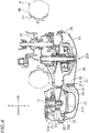
- Fig. 4 is a cross-sectional view taken along line IV-IV in Fig. 2 .
- a transmission case 25 Disposed to the left of the crankcase 11 are a transmission case 25, a V-beit type continuously variable transmission (hereinafter abbreviated as CVT) 20, and a transmission case cover 30 covering a left portion of the transmission case 25.
- the CVT 20, the transmission case 25, and the transmission case cover 30 together constitute a transmission unit 20A.
- the transmission case 25 includes a first case part 25A and a second case part 25B.
- the second case part 25B is disposed laterally outward of the first case part 25A.
- the term “laterally outward” herein means a direction away from the vehicle center line.
- the term “laterally inward” herein means a direction toward the vehicle center line.
- the first case part 25A and the second case part 25B are fastened together by bolts 26.
- the CVT 20 includes a drive pulley 21, a driven pulley 22 disposed to the rear of the drive pulley 21, and a V-belt 23 wrapped around the drive pulley 21 and the driven pulley 22.
- the drive pulley 21 is joined to the crankshaft 15.
- the drive pulley 21 may be joined directly to the crankshaft 15 or joined indirectly to the crankshaft 15 via another member.
- the drive pulley 21 is driven by the crankshaft 15 to rotate.
- the rear wheel 4 includes a wheel 4A, a tire 4B, and an axle shaft 4C.
- the driven pulley 22 is joined to the axle shaft 4C via gears, which are not shown in the drawings.
- the transmission case 25 is provided with an intake duct 27.
- the intake duct 27 is provided in the second case part 25B.
- the drive pulley 21 is provided with a fan 28 for sucking the air.
- the intake duct 27 is provided laterally outward of the drive pulley 21.
- a filter 21A is disposed between the drive pulley 21 and the intake duct 27.
- Fig. 5 is a cross-sectional view taken along line V-V in Fig. 2 .
- the intake duct 27 opens upwardly.
- the upper end of the intake duct 27 forms an inlet 27a for introducing the air therein.
- the inlet 27a is disposed frontward relative to the midpoint of the transmission unit 20A along the vehicle fore-and-aft axis.
- the inlet 27a is disposed frontward relative to the midpoint of the transmission case 25 along the vehicle fore-and-aft axis.
- the air sucked through the inlet 27a is cleaned by the filter 21A.
- the cleaned air then flows into the transmission case 25.
- an air outlet port for discharging air is formed in a portion of the second case part 25B that is beside or below the driven pulley 22.
- the fan 28 rotates in association with rotation of the drive pulley 21, the air is sucked from outside through the intake duct 27 into the transmission case 25.
- After flowing through a surrounding region around the CVT 20 the air is discharged out of the transmission case 25 through the air outlet port.
- the CVT 20 is cooled by the air.
- the transmission case cover 30 is furnished with a partition 31 extending laterally inward.
- the partition 31 has a partition plate 31A and a sponge 32.
- the partition 31 separates the intake duct 27 and the air outlet port from each other. This prevents the hot air that is discharged from the air outlet port from being sucked into the intake duct 27.
- the sponge 32 is disposed around the partition plate 31A. The sponge 32, however, may be eliminated.
- the partition 31 may consist only of the partition plate 31A.
- an air cleaner 40 is disposed above the transmission case 25 and the transmission case cover 30.
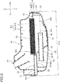
- Fig. 6 is a cross-sectional view taken along line VI-VI in Fig. 2 .
- the air cleaner 40 includes an air cleaner case 41, a filter element 43, an intake duct 44, and an air cleaner case cover 45.
- the air cleaner case 41 includes a first case part 41A and a second case part 41 B.
- the second case part 41B is disposed laterally inward of the first case part 41A.
- the second case part 41B is assembled to the first case part 41A.
- Fig. 7 is a side view illustrating the air cleaner 40 and the transmission unit 20A from which the air cleaner case cover 45 has been removed.
- the first case part 41A and the second case part 41B are fastened together by bolts 54.
- a partition plate 42 is disposed between the first case part 41A and the second case part 41B.
- the partition plate 42 includes a plate portion 42a and an opening 42b.
- the filter element 43 is fitted to the opening 42b.
- the interior of the air cleaner case 41 is divided by the filter element 43 into an unfiltered-air chamber 41a and a filtered-air chamber 41b.
- the unfiltered-air chamber 41a is positioned to the left of the filter element 43, and the filtered-air chamber 41b is positioned to the right of the filter element 43.
- the second case part 41B is connected to an intake pipe 85.
- the intake pipe 85 has an opening that is open inside the filtered-air chamber 41b. As illustrated in Fig. 3 , the intake pipe 85 is connected to the cylinder head 13. Although not shown in the drawings, an intake port is formed in the cylinder head 13, and the intake pipe 85 is connected to the intake port.
- the first case part 41A includes a first side plate 19 extending along the vehicle vertical axis and along the vehicle fore-and-aft axis, and a vertical plate 46 extending laterally outward from the first side plate 19 and extending along the vehicle vertical axis.
- Fig. 8 is a cross-sectional view taken along line VIII-VIII in Fig. 3 .
- the first case part 41A includes a horizontal plate 47 extending rearward from the lower end of the vertical plate 46 and extending along the vehicle lateral axis. The horizontal plate 47 is disposed above the transmission case 25 and spaced apart from the transmission case 25. As illustrated in Fig.
- the first case part 41A includes a second side plate 48 extending rearward along the vehicle fore-and-aft axis from a laterally outer end portion of the vertical plate 46 and extending along the vehicle vertical axis from a laterally outer end portion of the horizontal plate 47.
- the first case part 41A also includes a vertical plate 49 extending along the vehicle vertical axis from a rear end portion of the horizontal plate 47 and extending laterally inward from a rear end portion of the second side plate 48.
- the vertical plate 49 is positioned at the rear of the vertical plate 46.
- the vertical plate 46 may be perpendicular to the first side plate 19. However, in the present preferred embodiment, the vertical plate 46 is inclined rearward toward the left with respect to the first side plate 19.
- the first side plate 19, the vertical plate 46, the horizontal plate 47, the second side plate 48, and the vertical plate 49 may be either flat plates or curved plates.
- the shapes of the first side plate 19, the vertical plate 46, the horizontal plate 47, the second side plate 48, and the vertical plate 49 are not limited to specific shapes.
- An intake duct 44 penetrates through the vertical plate 46.
- the intake duct 44 includes an inlet 44a positioned in front of the vertical plate 46 and an outlet 44b positioned behind the vertical plate 46.
- the inlet 44a is formed into a shape that is wider toward its end. In other words, the inlet 44a is formed into what is called a bell mouth shape.
- the inlet 44a is disposed outside the air cleaner case 41.
- the outlet 44b is disposed inside the air cleaner case 41.
- the outlet 44b has an opening that opens in the interior of the unfiltered-air chamber 41a.
- the intake duct 44 extends along the vehicle fore-and-aft axis.
- the intake duct 44 may be either in a linear shape or a curved shape.
- the center line of the intake duct 44 may be either parallel or non-parallel to the vehicle fore-and-aft axis.
- the intake duct 44 is formed to be parallel to the vehicle fore-and-aft axis and in a linear shape.
- the filter element 43 is also disposed to be parallel to the vehicle fore-and-aft axis.
- the intake duct 44 is disposed parallel to the filter element 43.
- a collecting member 53 is secured to the vertical plate 49.
- the collecting member 53 is a member for collecting dust or water in the air, which is made of a sponge, for example.
- the material for the collecting member 53 is, however, not limited to a particular material.
- the collecting member 53 is disposed in the unfiltered-air chamber 41a inside the air cleaner case 41. At least a portion of the collecting member 53 is disposed on the extension line 44e of the center line of the intake duct 44 that extends from the outlet 44b.
- the air cleaner case cover 45 is disposed laterally outward of the air cleaner case 41.
- the air cleaner case cover 45 is assembled to the air cleaner case 41.
- the air cleaner case cover 45 is fastened to the first case part 41A by threaded fasteners.
- threaded fastener means a fastener having an external helical thread, and threaded fasteners include bolts and screws, for example.
- threaded fasteners 54 include bolts and screws, for example.
- the air cleaner case cover 45 has holes 62 positioned on the extension lines of the threaded fasteners 54.
- the threaded fasteners 54 can be screwed in or out by inserting a tool such as a screwdriver into the holes 62. Without removing the air cleaner case cover 45 from the first case part 41A, the threaded fasteners 54 can be screwed in or out. This means that without removing the air cleaner case cover 45 from the first case part 41A in advance, the threaded fasteners 54 can be rotated by a tool inserted into the holes 62, so that the first case part 41A can be removed from the second case part 41B. This affords easy replacement work of the filter element 43.
- the air cleaner case cover 45 is provided with a partition plate 55 for separating the inlet 27a of the intake duct 27 and the inlet 44a of the intake duct 44 from each other.
- the partition plate 55 extends laterally inwardly from the air cleaner case cover 45.
- the shape of the partition plate 55 is not limited to a particular shape. However, in the present preferred embodiment, the partition plate 55 extends gradually downward toward the rear when viewed in a side view of the vehicle, as illustrated in Fig. 8 . It is also possible that the partition plate 55 may be provided on the air cleaner case 41. That is, the air cleaner case cover 41 may be provided with a partition plate 55 extending laterally outward from the air cleaner case 41.
- the partition plate 55 may be formed by a partition plate part extending laterally inward from the air cleaner case cover 45 and another partition plate part extending laterally outward from the air cleaner case 41. It is possible that a sponge may or may not be disposed around the partition plate 55.
- the first side plate 19, the vertical plate 46, the partition plate 55, and the transmission case 25 together define an upstream intake chamber 56 around the inlet 44a of the intake duct 44.
- the inlet 44a of the intake duct 44 has an opening that is open in the interior of the upstream intake chamber 56.
- the air cleaner 40 includes a resonator 70 for reducing air intake noise.
- the resonator 70 includes a chamber 71, defined by the first side plate 19 of the first case part 41A and the plate portion 42a of the partition plate 42, and a tube 72 (see Fig. 7 ), extending laterally outward from the first case part 41A within the upstream intake chamber 56.
- An inlet 73 is formed at an end of the tube 72.
- the inlet 73 has an opening that is open in the interior of the upstream intake chamber 56.
- the inlet 73 is disposed above the intake duct 44.
- the center of the inlet 73 is positioned rearward relative to the front end of the intake duct 44.
- the chamber 71 is disposed between the upstream intake chamber 56 and the filtered-air chamber 41b. Note that the filtered-air chamber 41b forms the downstream intake chamber.
- the chamber 71 is formed in a laterally compact shape, which is elongated along the fore-and-aft axis. The lateral dimension of the chamber 71 is smaller than the fore-and-aft dimension thereof.
- Fig. 9 is a cross-sectional view taken along line IX-IX in Fig. 2 .
- the air cleaner case cover 45 includes an overlaying portion 51 overlaying the second side plate 48 of the air cleaner case 41, and a downwardly-extending portion 52 extending downward from the overlaying portion 51.
- the overlaying portion 51 is not spaced away from the second side plate 48, and no gap such as to allow the air to flow through is provided between the overlaying portion 51 and the second side plate 48.
- the downwardly-extending portion 52, the horizontal plate 47, and the transmission case cover 30 together define an intake passage 60 extending along the vehicle fore-and-aft axis.
- the front end portion of the intake passage 60 is connected to the upstream intake chamber 56.
- the rear end portion of the intake passage 60 is open.
- the rear end portion of the intake passage 60 forms a rear intake port 60a.
- the rear intake port 60a is positioned rearward relative to the vehicle fore-and-aft midpoint 41m (see Fig. 6 ) of the air cleaner case 41.
- a pre-filter element 57 is disposed between the horizontal plate 47 and the transmission case cover 30 and inside the intake passage 60.
- the pre-filter element 57 serves to clean the air A2 passing through the intake passage 60.
- the form of the pre-filter element 57 and the materials for the pre-filter element 57 are not limited to any particular form or material.
- the pre-filter element 57 is formed of sponge.
- a gap is provided behind the rear intake port 60a between the air cleaner case cover 45 and the transmission case cover 30.
- a portion of the air cleaner case cover 45 that is located rearward relative to the rear intake port 60a is referred to as a rear intake section 45a.
- a gap that is at least sidewardly open is provided between the rear intake section 45a and the transmission case cover 30.
- the air A1 that is sucked sidewardly through this gap flows through the rear intake port 60a into the intake passage 60.
- the transmission case cover 30 includes a lower inclined portion 30a inclined laterally more outward toward its top, and an upper inclined portion 30b inclined more inward toward its top.
- the upper inclined portion 30b is positioned above the lower inclined portion 30a.
- the upper inclined portion 30b and the lower inclined portion 30a are disposed below the rear intake section 45a, as viewed in a side view of the vehicle.
- the front portion of the air cleaner case 41 is disposed above the intake duct 27. As illustrated in Fig. 8 , the lower end 41g of the front portion 41f of the air cleaner case 41 is disposed downward relative to the upper end 27t of the intake duct 27. The front portion 41f of the air cleaner case 41 covers a surrounding portion of the inlet 27a of the intake duct 27. As illustrated in Fig. 2 , the air cleaner case cover 45 includes a front intake section 45b positioned at a side of the front portion 41f of the air cleaner case 41. The lower end of the front intake section 45b is disposed downward relative to the upper end of the intake duct 27. As illustrated in Fig.
- the front portion 41f of the air cleaner case 41, the partition plate 55, and the front intake section 45b together define an intake chamber 57A around the inlet 27a of the intake duct 27.
- the inlet 27a of the intake duct 27 has an opening that is open in the interior of the intake chamber 57A.
- a gap is provided vertically between the front portion 41f of the air cleaner case 41 and the transmission case cover 30. This gap forms a front intake port 57a for sucking air from the front toward the intake duct 27. As illustrated in Fig. 2 , a gap is provided vertically between the front intake section 45b of the air cleaner case 45 and the transmission case cover 30. This gap forms a side intake port 57b for sucking air from the side toward the intake duct 27.
- the front intake section 45b is provided with ribs 58 extending along the vehicle fore-and-aft axis.
- the ribs 58 are linear protrusions protruding laterally outward and extending along the vehicle fore-and-aft axis. Although a plurality of ribs 58 are provided in the present preferred embodiment, it is possible that the number of the ribs 58 may be 1.
- the area of the opening between the air cleaner case cover 45 and the transmission case cover 30 is larger than the minimum flow passage cross-sectional area of the intake duct 27.
- the total area S1+S2 of the openings of the front intake port 57a and the side intake port 57b is larger than the minimum flow passage cross-sectional area of the intake duct 27. It is also possible that the area S2 of the opening of the side intake port 57b may be larger than the minimum flow passage cross-sectional area of the intake duct 27.
- the term "flow passage cross-sectional area” means an area of the cross section of a flow passage that is orthogonal to the central axis of the flow passage.
- the air cleaner case cover 45 includes a wall portion 45d positioned behind the plate member 59.
- the lower end of the wall portion 45d is positioned downward relative to the upper end of the plate member 59.
- the plate member 59 and the wall portion 45d together form a labyrinth structure 65 at the rear of the intake duct 27.
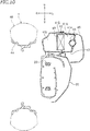
- Fig. 11 is a cross-sectional view taken along line XI-XI in Fig. 2 .
- a laterally outward portion 27c of the intake duct 27 is inclined laterally more outward toward its top, with respect to the vertical line.
- a gap 27g between the portion 27c and the front intake section 45b of the air cleaner case 45 narrows toward the end of the intake duct 27.
- the intake duct 27 may have a portion in which a gap with the transmission case cover 30 narrows toward its end.
- the upper end of the intake duct 27 is positioned upward relative to the lower end of the front intake section 45b.
- the front intake section 45b and the upper portion of the intake duct 27 together form a labyrinth structure.
- the labyrinth structure 66 is formed above the transmission case 25 and laterally inward of the intake duct 27.
- the labyrinth structure 66 includes a plate member 66a extending upward from the transmission case cover 30 and a plate member 66b extending downward from the air cleaner case 41.
- the upper end of the plate member 66a is positioned upward relative to the lower end of the plate member 66b.
- the plate member 66a is disposed laterally outward relative to the plate member 66b in the present preferred embodiment, the plate member 66a may be disposed laterally inward relative to the plate member 66b.
- the plate member 66a is provided on the transmission case cover 30 in the present preferred embodiment, the plate member 66a may be provided on the transmission case 25.
- the plate member 66a is provided on the second case part 41B, it is also possible that the plate member 66a be provided on the first case part 41A.
- a sponge 67 is disposed around the plate member 66b. It is, however, also possible to eliminate the sponge 67.
- the motorcycle 1 according to the present preferred embodiment does not require a long duct extending upward from the transmission case 25. This prevents the vehicle from getting larger in size.
- the inlet 27a of the intake duct 27 for introducing air into the transmission case 25 is supplied with the air that is sucked from the side intake port 57b formed between the air cleaner case cover 45 and the transmission case cover 30.
- the inlet 44a of the intake duct 44 for introducing air into the air cleaner case 41 is supplied with the air that is sucked from the rear intake port 60a formed between the air cleaner case cover 45 and the transmission case cover 30. This makes it possible to prevent dust and water from entering the air cleaner 40 and the CVT 20.
- the inlet 27a of the intake duct 27 and the inlet 44a of the intake duct 44 are separated by the partition plate 55. This makes it possible to supply a sufficient amount of air to both the air cleaner 40 and the CVT 20.
- the motorcycle 1 according to the present preferred embodiment prevents dust and water from entering the air cleaner 40 and the CVT 20, keeps the vehicle size from becoming larger, and is capable of supplying a sufficient amount of air to both the air cleaner 40 and the CVT 20.
- the labyrinth structure 65 is provided behind the intake duct 27, as illustrated in Fig. 7 .
- This labyrinth structure 65 makes it possible to prevent dust and water from entering the air cleaner 40 from the rear of the intake duct 27. As a result, dust and water are prevented from entering the CVT 20 more effectively.
- the intake duct 27 includes the portion 27c in which the gap 27g with the air cleaner case cover 45 or with the transmission case cover 30 narrows toward the end of the intake duct 27. As a result, dust and water are prevented from entering the intake duct 27 more effectively.
- the ribs 58 extending along the vehicle fore-and-aft axis are provided on a portion of the air cleaner case cover 45 above the side intake port 57b, as illustrated in Fig. 2 .
- Water running along the surface of the air cleaner case cover 45 is guided to the rear by the ribs 58 easily. This prevents water from entering the side intake port 57b and thus prevents water from entering the CVT 20 more effectively.
- the labyrinth structure 66 is formed above the transmission case 25 and laterally inward of the intake duct 27, as illustrated in Fig. 11 .
- This labyrinth structure 66 can prevent dust and water swirled up by the rear wheel 4 from entering the intake duct 27. As a result, dust and water are prevented from entering the CVT 20 more effectively.
- the inlet 27a of the intake duct 27 opens upwardly, and the inlet 44a of the intake duct 44 opens frontwardly at a position rearward relative to the inlet 27a.
- the partition plate 55 extends between the inlet 27a and the inlet 44a so as to extend gradually downward toward the rear. The partition plate 55 disposed in this way can guide air toward the inlet 27a and the inlet 44a. This makes it possible to supply a sufficient amount of air to both the air cleaner 40 and the CVT 20.
- the horizontal plate 47 of the air cleaner case 41, the transmission unit 20A, and the downwardly-extending portion 52 of the air cleaner case cover 45 together form the intake passage 60 connected to the upstream intake chamber 56.
- No gap for forming the intake passage 60 is provided between the overlaying portion 51 of the air cleaner case cover 45 and the second side plate 48 of the air cleaner case 41.
- the air cleaner case cover 45 is inhibited from protruding laterally outward, so that the lateral dimension can be kept small.
- the inlet 44a of the intake duct 44 is disposed frontward relative to the vehicle fore-and-aft midpoint 41m of the air cleaner case 41, and the rear intake port 60a of the intake passage 60 is positioned rearward relative to the vehicle fore-and-aft midpoint 41m of the air cleaner case 41.
- This enables the intake passage 60 that is upstream of the intake duct 44 to have a sufficient length.
- the intake passage 60 that is upstream of the intake duct 44 is allowed to have a sufficient length, so that the lateral dimension can be kept small.
- the transmission case 25 and the transmission case cover 30 of the transmission unit 20A are separate parts.
- the transmission case 25 and the transmission case cover 30 may be an integral part.
- the first case part 41A and the air cleaner case cover 45 of the air cleaner 40 are separate parts.
- the first case part 41A and the air cleaner case cover 45 may be an integral part.
- the intake duct 27 and the transmission case cover 30 are made of synthetic resin.
- the first case part 41A, the second case part 41B, the partition plate 42, the intake duct 44, and the intake pipe 85 are also made of synthetic resin.
- the material for these components is not limited to synthetic resin.
Landscapes
- Engineering & Computer Science (AREA)
- Mechanical Engineering (AREA)
- Chemical & Material Sciences (AREA)
- Combustion & Propulsion (AREA)
- General Engineering & Computer Science (AREA)
- General Details Of Gearings (AREA)
Abstract
Description
- The present invention relates to scooter type motorcycles.
- A scooter type motorcycle is conventionally known which is equipped with an internal combustion engine, a V-belt type continuously variable transmission (hereinafter referred to as "CVT"), and an air cleaner disposed above a transmission case accommodating the CVT.
- The CVT produces heat during operation. When the temperature of the CVT rises, the durability of the V-belt deteriorates. In an attempt to improve the durability of the V-belt, air is introduced into the transmission case so that the CVT is cooled by the air. However, if dust or water adheres to the V-belt, the performance of the CVT degrades. In order to ensure sufficient performance for the CVT, it is important to prevent water and dust from entering the transmission case.
-
JP 2007-314165 A -
JP 2012-245890 A - The scooter type motorcycle disclosed in
JP 2007-314165 A JP 2012-245890 - The present invention has been accomplished in view of the foregoing and other problems, and it is an object of the invention to provide a scooter type motorcycle that prevents dust and water from entering the air cleaner and the CVT, inhibits the vehicle size from getting larger, and is capable of supplying a sufficient amount of air to both the air cleaner and the CVT. According to the present invention said object is solved by a scooter type motorcycle having the features of
independent claim 1. Preferred embodiments are laid down in the dependent claims. - Accordingly, a scooter type motorcycle includes: a rear wheel; a transmission case disposed sideward of the rear wheel - the transmission case is disposed at least partly overlapping of the rear wheel in a side view of the motorcycle, i.e. the view along a lateral axis in left/right direction -; a V-belt type continuously variable transmission disposed in the transmission case; a first intake duct provided on the transmission case and including a first inlet positioned frontward relative to a vehicle fore-and-aft midpoint of the transmission case; an air cleaner case disposed above the transmission case - the air cleaner case is disposed at least partly overlapping of the transmission case in a top view of the motorcycle, i.e. the view along a vertical axis in up/down direction -; a second intake duct provided on the air cleaner case and including a second inlet positioned frontward relative to a vehicle fore-and-aft midpoint of the air cleaner case; an air cleaner case cover disposed laterally outward of the air cleaner case and the second intake duct; a transmission case cover disposed laterally outward of the transmission case and the first intake duct and disposed below the air cleaner case cover- the transmission case cover is disposed at least partly overlapping of the transmission case cover in a bottom view of the motorcycle, i.e. the view along a vertical axis in up/down direction -; and a partition plate disposed between the first inlet of the first intake duct and the second inlet of the second intake duct. The area of the opening between the air cleaner case cover and the transmission case cover is larger than a minimum flow passage cross-sectional area of the first intake duct. A side intake port for sucking air toward the first inlet is formed between the air cleaner case cover and the transmission case cover, and laterally outward of the first inlet. A rear intake port for sucking air toward the second inlet is formed between the air cleaner case cover and the transmission case cover, and rearward relative to the first inlet. At least a portion of the rear intake port is disposed laterally inward relative to the side intake port.
- The just-described scooter type motorcycle does not require a long duct extending upward from the transmission case. This prevents the vehicle from getting larger in size. The first inlet of the first intake duct for introducing air into the transmission case is supplied with the air that is sucked from the side intake port formed between the air cleaner case cover and the transmission case cover. The second inlet of the second intake duct for introducing air into the air cleaner case is supplied with the air that is sucked from the rear intake port formed between the air cleaner case cover and the transmission case cover. This makes it possible to prevent dust and water from entering the air cleaner and the CVT. Moreover, the first inlet and the second inlet are separated by the partition plate. This makes it possible to supply a sufficient amount of air to both the air cleaner and the CVT. Thus, the just-described scooter type motorcycle prevents dust and water from entering the air cleaner and the CVT, keeps the vehicle size from getting larger, and is capable of supplying a sufficient amount of air to both the air cleaner and the CVT.
- In one preferred embodiment, a plate member extending laterally is provided on a portion of the transmission case cover rearward of the first intake duct. The air cleaner case cover includes a wall portion being positioned behind the plate member and including a lower end positioned downward relative to an upper end of the plate member. The plate member and the wall portion together form a labyrinth structure positioned rearward of the first intake duct.
- The just-described preferred embodiment makes it possible to prevent dust and water from entering the air cleaner from the rear of the first intake duct. This prevents dust and water from entering the CVT.
- In another preferred embodiment, the first intake duct includes a portion in which a gap between the first intake duct and the air cleaner case cover or between the first intake duct and the transmission case cover narrows toward an end of the first intake duct.
- The just-described preferred embodiment makes it possible to prevent dust and water from entering the first intake duct.
- In another preferred embodiment, a rib extending along a vehicle fore-and-aft axis is provided on a portion of the air cleaner case cover above the side intake port - the air cleaner case cover is disposed at least partly overlapping of the side intake port in a top view of the motorcycle, i.e. the view along a vertical axis in up/down direction.
- According to the just-described preferred embodiment, water running along the surface of the air cleaner case cover is guided to the rear by the rib easily. This prevents the water from entering the side intake port and thus prevents water from entering the CVT.
- In another preferred embodiment, a labyrinth structure is formed above the transmission case - the labyrinth structure is disposed at least partly overlapping of the transmission case in a top view of the motorcycle, i.e. the view along a vertical axis in up/down direction - and laterally inward of the first intake duct.
- The just-described preferred embodiment makes it possible to prevent dust and water that are swirled up by the rear wheel from entering the first intake duct. As a result, dust and water are prevented from entering the CVT.
- In another preferred embodiment, the first inlet opens upwardly, and the second inlet opens frontwardly at a position rearward relative to the first inlet, the partition plate extends between the first inlet and the second inlet so as to extend gradually downward toward the rear.
- The just-described preferred embodiment enables the partition plate to guide air toward the first inlet and the second inlet. This allows a sufficient amount of air to be supplied to both the air cleaner and the CVT.
- In another preferred embodiment, the air cleaner case includes: a first side plate extending along a vehicle vertical axis and a vehicle fore-and-aft axis; a vertical plate, disposed upward relative to the transmission case, extending laterally outward from the first side plate and extending along the vehicle vertical axis; a horizontal plate extending rearward from a lower end of the vertical plate and extending along a vehicle lateral axis, the horizontal plate spaced upwardly apart from the transmission case; and a second side plate extending rearward along the vehicle fore-and-aft axis from a laterally outer end portion of the vertical plate and extending along the vehicle vertical axis from a laterally outer end portion of the horizontal plate. The second intake duct penetrates through the vertical plate. The vertical plate, the horizontal plate, and the second side plate together define at least a portion of a downstream intake chamber. The air cleaner case cover includes a spacing portion disposed sideward of the first side plate and spaced apart from the first side plate, an overlaying portion overlaying the second side plate so as not to be spaced apart from the second side plate, and a downwardly-extending portion extending downward from the overlaying portion. The spacing portion of the air cleaner case cover, the first side plate, and the vertical plate together define at least a portion of an upstream intake chamber. The horizontal plate, the transmission case, and the downwardly-extending portion of the air cleaner case cover together form an intake passage being connected to the upstream intake chamber and having the rear intake port.
- In the just-described preferred embodiment, the intake passage for introducing air toward the second intake duct is formed between the transmission case and the downwardly-extending portion of the air cleaner case cover. No gap for forming the intake passage is provided between the overlaying portion of the air cleaner case cover and the second side plate of the air cleaner case. As a result, the air cleaner case cover is inhibited from protruding laterally outward, so that the lateral dimension can be kept small. In addition, the inlet of the second intake duct is disposed frontward relative to the vehicle fore-and-aft midpoint of the air cleaner case, and the rear intake port of the intake passage is positioned rearward relative to the vehicle fore-and-aft midpoint of the air cleaner case. This enables the intake passage that is upstream of the second intake duct to have a sufficient length. Thus, the intake passage that is upstream of the second intake duct is allowed to have a sufficient length in the air cleaner, and also the lateral dimension can be kept small.
- The present invention makes it possible to provide a scooter type motorcycle that prevents dust and water from entering the air cleaner and the CVT, inhibits the vehicle size from getting larger, and is capable of supplying a sufficient amount of air to both the air cleaner and the CVT.
-
-
Fig. 1 is a side view illustrating a scooter type motorcycle according to a preferred embodiment. -
Fig. 2 is an enlarged side view illustrating a rear portion of the scooter type motorcycle. -
Fig. 3 is a plan view illustrating a power unit and a rear wheel. -
Fig. 4 is a cross-sectional view taken along line IV-IV inFig. 2 . -
Fig. 5 is a cross-sectional view taken along line V-V inFig. 2 . -
Fig. 6 is a cross-sectional view taken along line VI-VI inFig. 2 . -
Fig. 7 is a side view illustrating an air cleaner and a transmission unit from which an air cleaner case cover has been removed. -
Fig. 8 is a cross-sectional view taken along line VIII-VIII inFig. 3 . -
Fig. 9 is a cross-sectional view taken along line IX-IX inFig. 2 . -
Fig. 10 is a cross-sectional view taken along line X-X inFig. 2 . -
Fig. 11 is a cross-sectional view taken along line XI-XI inFig. 2 . -
Fig. 12A is a schematic diagram for illustrating an area of opening between an air cleaner case cover and a transmission case cover. -
Fig. 12B is a schematic diagram for illustrating areas of opening of a front intake port and a side intake port. - Hereinbelow, a scooter type motorcycle according to one preferred embodiment will be described with reference to the drawings.
Fig. 1 is a side view illustrating a scooter type motorcycle (hereinafter referred to simply as "motorcycle") 1 according to the present preferred embodiment.Fig. 2 is an enlarged side view illustrating part of a rear portion of themotorcycle 1. As illustrated inFig. 1 , themotorcycle 1 includes a body frame, which is not shown, afront wheel 3, arear wheel 4, a handlebar 5, aseat 6, and apower unit 10. Thepower unit 10 is supported by a pivot shaft (not shown) swingably to the body frame. - In the following description, unless specifically indicated otherwise, the terms "front," "rear," "left," "right," "up," and "down" respectively refer to front, rear, left, right, up, and down as defined based on the perspective of an imaginary rider (not shown) seated on the
seat 6 when themotorcycle 1 is assumed to be standing at a standstill on a horizontal plane in an unloaded condition. The phrase "unloaded condition" means a condition in which themotorcycle 1 does not carry any rider or fuel. Reference characters F, Rr, L, R, U, and D in the drawings represent front, rear, left, right, up, and down, respectively. The term "frontward" herein means motorcycle's frontward in its fore-and-aft orientation. The term "rearward" herein means motorcycle's rearward in its fore-and-aft orientation. - Unless specifically indicated otherwise, the term "frontward" is not intended to be limited to a horizontal frontward direction, but is meant to include directions inclined within the range of -45° to +45° with respect to the horizontal frontward direction. Likewise, the term "rearward" is not intended to be limited to a horizontal rearward direction, but is meant to include directions inclined within the range of -45° to +45° with respect to the horizontal rearward direction. The term "leftward" is not intended to be limited to a laterally leftward direction, but is meant to include directions inclined within the range of -45° to +45° with respect to that direction. Likewise, the term "rightward" is not intended to be limited to a laterally rightward direction, but is meant to include directions inclined within the range of - 45° to +45° with respect to that direction. The term "upward" is not intended to be limited to a vertically upward direction, but is meant to include directions inclined within the range of -45° to +45° with respect to the vertically upward direction. The term "downward" is not intended to be limited to a vertically downward direction, but is meant to include directions inclined within the range of -45° to +45° with respect to the vertically downward direction.
- Unless specifically indicated otherwise, a "front portion" of an item means a portion of the item that is located frontward relative to the vehicle fore-and-aft midpoint of the item. A "rear portion" of an item means a portion of the item that is located rearward relative to the vehicle fore-and-aft midpoint of the item. An "upper portion" of an item means a portion of the item that is located upward relative to the vertical midpoint of the item. A "lower portion" of an item means a portion of the item that is located downward relative to the vertical midpoint of the item. A "left portion" of an item means a portion of the item that is located leftward relative to the lateral midpoint of the item. A "right portion" of an item means a portion of the item that is located rightward relative to the lateral midpoint of the item. Note that the term "lateral axis" herein is used interchangeably to refer to a vehicle's widthwise axis, i.e., a left-to-right/right-to-left axis.
- As illustrated in
Fig. 3 , thepower unit 10 includes aninternal combustion engine 10A as a driving power source. Thepower unit 10 includes a crankcase 11, acylinder body 12 connected to the crankcase 11, acylinder head 13 connected to thecylinder body 12, and acylinder head cover 14 connected to thecylinder head 13. A crankshaft 15 (seeFig. 4 ) is disposed inside the crankcase 11. Although not shown in the drawings, at least one cylinder that slidably accommodates a piston is disposed inside thecylinder body 12. The piston(s) and the crankshaft are coupled to each other via a connecting rod. Thecylinder body 12 and thecylinder head 13 together forms a combustion chamber above the piston(s). The center line of the cylinder (i.e., the cylinder axis) extends frontward. The angle formed by the cylinder axis and the horizontal line as viewed in a side view of the vehicle is not limited to any specific angle. However, in the present preferred embodiment, the angle is set at 45 degrees or less. The just-mentioned angle may be from 0 degrees to 30 degrees, or may be from 0 degrees to 15 degrees. -
Fig. 4 is a cross-sectional view taken along line IV-IV inFig. 2 . Disposed to the left of the crankcase 11 are atransmission case 25, a V-beit type continuously variable transmission (hereinafter abbreviated as CVT) 20, and a transmission case cover 30 covering a left portion of thetransmission case 25. TheCVT 20, thetransmission case 25, and the transmission case cover 30 together constitute atransmission unit 20A. Thetransmission case 25 includes afirst case part 25A and asecond case part 25B. Thesecond case part 25B is disposed laterally outward of thefirst case part 25A. It should be noted that the term "laterally outward" herein means a direction away from the vehicle center line. On the other hand, the term "laterally inward" herein means a direction toward the vehicle center line. Thefirst case part 25A and thesecond case part 25B are fastened together bybolts 26. - The
CVT 20 includes adrive pulley 21, a drivenpulley 22 disposed to the rear of thedrive pulley 21, and a V-belt 23 wrapped around thedrive pulley 21 and the drivenpulley 22. Thedrive pulley 21 is joined to thecrankshaft 15. Thedrive pulley 21 may be joined directly to thecrankshaft 15 or joined indirectly to thecrankshaft 15 via another member. Thedrive pulley 21 is driven by thecrankshaft 15 to rotate. Therear wheel 4 includes awheel 4A, atire 4B, and an axle shaft 4C. The drivenpulley 22 is joined to the axle shaft 4C via gears, which are not shown in the drawings. - The
transmission case 25 is provided with anintake duct 27. Theintake duct 27 is provided in thesecond case part 25B. Thedrive pulley 21 is provided with afan 28 for sucking the air. Theintake duct 27 is provided laterally outward of thedrive pulley 21. Afilter 21A is disposed between thedrive pulley 21 and theintake duct 27.Fig. 5 is a cross-sectional view taken along line V-V inFig. 2 . Theintake duct 27 opens upwardly. The upper end of theintake duct 27 forms aninlet 27a for introducing the air therein. Theinlet 27a is disposed frontward relative to the midpoint of thetransmission unit 20A along the vehicle fore-and-aft axis. Theinlet 27a is disposed frontward relative to the midpoint of thetransmission case 25 along the vehicle fore-and-aft axis. The air sucked through theinlet 27a is cleaned by thefilter 21A. The cleaned air then flows into thetransmission case 25. Although not shown, an air outlet port for discharging air is formed in a portion of thesecond case part 25B that is beside or below the drivenpulley 22. As thefan 28 rotates in association with rotation of thedrive pulley 21, the air is sucked from outside through theintake duct 27 into thetransmission case 25. After flowing through a surrounding region around theCVT 20, the air is discharged out of thetransmission case 25 through the air outlet port. TheCVT 20 is cooled by the air. - As illustrated in
Fig. 4 , the transmission case cover 30 is furnished with apartition 31 extending laterally inward. Thepartition 31 has apartition plate 31A and asponge 32. Thepartition 31 separates theintake duct 27 and the air outlet port from each other. This prevents the hot air that is discharged from the air outlet port from being sucked into theintake duct 27. Thesponge 32 is disposed around thepartition plate 31A. Thesponge 32, however, may be eliminated. Thepartition 31 may consist only of thepartition plate 31A. - As illustrated in
Fig. 2 , anair cleaner 40 is disposed above thetransmission case 25 and the transmission case cover 30.Fig. 6 is a cross-sectional view taken along line VI-VI inFig. 2 . As illustrated inFig. 6 , theair cleaner 40 includes an aircleaner case 41, afilter element 43, anintake duct 44, and an aircleaner case cover 45. - The
air cleaner case 41 includes afirst case part 41A and asecond case part 41 B. Thesecond case part 41B is disposed laterally inward of thefirst case part 41A. Thesecond case part 41B is assembled to thefirst case part 41A.Fig. 7 is a side view illustrating theair cleaner 40 and thetransmission unit 20A from which the air cleaner case cover 45 has been removed. As illustrated inFig. 7 , thefirst case part 41A and thesecond case part 41B are fastened together bybolts 54. As illustrated inFig. 6 , apartition plate 42 is disposed between thefirst case part 41A and thesecond case part 41B. Thepartition plate 42 includes aplate portion 42a and anopening 42b. Thefilter element 43 is fitted to theopening 42b. The interior of theair cleaner case 41 is divided by thefilter element 43 into an unfiltered-air chamber 41a and a filtered-air chamber 41b. The unfiltered-air chamber 41a is positioned to the left of thefilter element 43, and the filtered-air chamber 41b is positioned to the right of thefilter element 43. - The
second case part 41B is connected to anintake pipe 85. Theintake pipe 85 has an opening that is open inside the filtered-air chamber 41b. As illustrated inFig. 3 , theintake pipe 85 is connected to thecylinder head 13. Although not shown in the drawings, an intake port is formed in thecylinder head 13, and theintake pipe 85 is connected to the intake port. - The
first case part 41A includes afirst side plate 19 extending along the vehicle vertical axis and along the vehicle fore-and-aft axis, and avertical plate 46 extending laterally outward from thefirst side plate 19 and extending along the vehicle vertical axis.Fig. 8 is a cross-sectional view taken along line VIII-VIII inFig. 3 . As illustrated inFig. 8 , thefirst case part 41A includes ahorizontal plate 47 extending rearward from the lower end of thevertical plate 46 and extending along the vehicle lateral axis. Thehorizontal plate 47 is disposed above thetransmission case 25 and spaced apart from thetransmission case 25. As illustrated inFig. 6 , thefirst case part 41A includes asecond side plate 48 extending rearward along the vehicle fore-and-aft axis from a laterally outer end portion of thevertical plate 46 and extending along the vehicle vertical axis from a laterally outer end portion of thehorizontal plate 47. Thefirst case part 41A also includes avertical plate 49 extending along the vehicle vertical axis from a rear end portion of thehorizontal plate 47 and extending laterally inward from a rear end portion of thesecond side plate 48. Thevertical plate 49 is positioned at the rear of thevertical plate 46. Thevertical plate 46 may be perpendicular to thefirst side plate 19. However, in the present preferred embodiment, thevertical plate 46 is inclined rearward toward the left with respect to thefirst side plate 19. Thefirst side plate 19, thevertical plate 46, thehorizontal plate 47, thesecond side plate 48, and thevertical plate 49 may be either flat plates or curved plates. The shapes of thefirst side plate 19, thevertical plate 46, thehorizontal plate 47, thesecond side plate 48, and thevertical plate 49 are not limited to specific shapes. - An
intake duct 44 penetrates through thevertical plate 46. Theintake duct 44 includes aninlet 44a positioned in front of thevertical plate 46 and an outlet 44b positioned behind thevertical plate 46. Theinlet 44a is formed into a shape that is wider toward its end. In other words, theinlet 44a is formed into what is called a bell mouth shape. Theinlet 44a is disposed outside theair cleaner case 41. The outlet 44b is disposed inside theair cleaner case 41. The outlet 44b has an opening that opens in the interior of the unfiltered-air chamber 41a. Theintake duct 44 extends along the vehicle fore-and-aft axis. Theintake duct 44 may be either in a linear shape or a curved shape. The center line of theintake duct 44 may be either parallel or non-parallel to the vehicle fore-and-aft axis. In the present preferred embodiment, theintake duct 44 is formed to be parallel to the vehicle fore-and-aft axis and in a linear shape. Thefilter element 43 is also disposed to be parallel to the vehicle fore-and-aft axis. Theintake duct 44 is disposed parallel to thefilter element 43. - A collecting
member 53 is secured to thevertical plate 49. The collectingmember 53 is a member for collecting dust or water in the air, which is made of a sponge, for example. The material for the collectingmember 53 is, however, not limited to a particular material. The collectingmember 53 is disposed in the unfiltered-air chamber 41a inside theair cleaner case 41. At least a portion of the collectingmember 53 is disposed on theextension line 44e of the center line of theintake duct 44 that extends from the outlet 44b. - The air cleaner case cover 45 is disposed laterally outward of the
air cleaner case 41. The air cleaner case cover 45 is assembled to theair cleaner case 41. Although not shown in the drawings, the air cleaner case cover 45 is fastened to thefirst case part 41A by threaded fasteners. In the present description, the term "threaded fastener" means a fastener having an external helical thread, and threaded fasteners include bolts and screws, for example. As already mentioned above, thefirst case part 41A and thesecond case part 41B of theair cleaner case 41 are fastened to each other by threaded fasteners 54 (seeFig. 7 ). The air cleaner case cover 45 hasholes 62 positioned on the extension lines of the threadedfasteners 54. The threadedfasteners 54 can be screwed in or out by inserting a tool such as a screwdriver into theholes 62. Without removing the air cleaner case cover 45 from thefirst case part 41A, the threadedfasteners 54 can be screwed in or out. This means that without removing the air cleaner case cover 45 from thefirst case part 41A in advance, the threadedfasteners 54 can be rotated by a tool inserted into theholes 62, so that thefirst case part 41A can be removed from thesecond case part 41B. This affords easy replacement work of thefilter element 43. - As illustrated in
Figs. 6 and8 , the air cleaner case cover 45 is provided with apartition plate 55 for separating theinlet 27a of theintake duct 27 and theinlet 44a of theintake duct 44 from each other. Thepartition plate 55 extends laterally inwardly from the aircleaner case cover 45. The shape of thepartition plate 55 is not limited to a particular shape. However, in the present preferred embodiment, thepartition plate 55 extends gradually downward toward the rear when viewed in a side view of the vehicle, as illustrated inFig. 8 . It is also possible that thepartition plate 55 may be provided on theair cleaner case 41. That is, the air cleaner case cover 41 may be provided with apartition plate 55 extending laterally outward from theair cleaner case 41. Alternatively, thepartition plate 55 may be formed by a partition plate part extending laterally inward from the air cleaner case cover 45 and another partition plate part extending laterally outward from theair cleaner case 41. It is possible that a sponge may or may not be disposed around thepartition plate 55. Thefirst side plate 19, thevertical plate 46, thepartition plate 55, and thetransmission case 25 together define anupstream intake chamber 56 around theinlet 44a of theintake duct 44. Theinlet 44a of theintake duct 44 has an opening that is open in the interior of theupstream intake chamber 56. - As illustrated in
Fig. 6 , theair cleaner 40 includes aresonator 70 for reducing air intake noise. Theresonator 70 includes achamber 71, defined by thefirst side plate 19 of thefirst case part 41A and theplate portion 42a of thepartition plate 42, and a tube 72 (seeFig. 7 ), extending laterally outward from thefirst case part 41A within theupstream intake chamber 56. Aninlet 73 is formed at an end of thetube 72. Theinlet 73 has an opening that is open in the interior of theupstream intake chamber 56. In the present preferred embodiment, theinlet 73 is disposed above theintake duct 44. The center of theinlet 73 is positioned rearward relative to the front end of theintake duct 44. It should be noted, however, that the position of theinlet 73 is not limited to a particular position. Thechamber 71 is disposed between theupstream intake chamber 56 and the filtered-air chamber 41b. Note that the filtered-air chamber 41b forms the downstream intake chamber. Thechamber 71 is formed in a laterally compact shape, which is elongated along the fore-and-aft axis. The lateral dimension of thechamber 71 is smaller than the fore-and-aft dimension thereof. -
Fig. 9 is a cross-sectional view taken along line IX-IX inFig. 2 . As illustrated inFig. 9 , the air cleaner case cover 45 includes an overlayingportion 51 overlaying thesecond side plate 48 of theair cleaner case 41, and a downwardly-extendingportion 52 extending downward from the overlayingportion 51. The overlayingportion 51 is not spaced away from thesecond side plate 48, and no gap such as to allow the air to flow through is provided between the overlayingportion 51 and thesecond side plate 48. As illustrated inFig. 8 , the downwardly-extendingportion 52, thehorizontal plate 47, and the transmission case cover 30 together define anintake passage 60 extending along the vehicle fore-and-aft axis. The front end portion of theintake passage 60 is connected to theupstream intake chamber 56. The rear end portion of theintake passage 60 is open. The rear end portion of theintake passage 60 forms arear intake port 60a. Therear intake port 60a is positioned rearward relative to the vehicle fore-and-aft midpoint 41m (seeFig. 6 ) of theair cleaner case 41. Apre-filter element 57 is disposed between thehorizontal plate 47 and the transmission case cover 30 and inside theintake passage 60. Thepre-filter element 57 serves to clean the air A2 passing through theintake passage 60. The form of thepre-filter element 57 and the materials for thepre-filter element 57 are not limited to any particular form or material. Herein, thepre-filter element 57 is formed of sponge. - As illustrated in
Fig. 9 , a gap is provided behind therear intake port 60a between the air cleaner case cover 45 and the transmission case cover 30. Hereinafter, a portion of the air cleaner case cover 45 that is located rearward relative to therear intake port 60a is referred to as arear intake section 45a. A gap that is at least sidewardly open is provided between therear intake section 45a and the transmission case cover 30. The air A1 that is sucked sidewardly through this gap flows through therear intake port 60a into theintake passage 60. In a region that is rearward relative to therear intake port 60a, the transmission case cover 30 includes a lowerinclined portion 30a inclined laterally more outward toward its top, and an upperinclined portion 30b inclined more inward toward its top. The upperinclined portion 30b is positioned above the lowerinclined portion 30a. As illustrated inFig. 2 , the upperinclined portion 30b and the lowerinclined portion 30a are disposed below therear intake section 45a, as viewed in a side view of the vehicle. - The front portion of the
air cleaner case 41 is disposed above theintake duct 27. As illustrated inFig. 8 , thelower end 41g of thefront portion 41f of theair cleaner case 41 is disposed downward relative to theupper end 27t of theintake duct 27. Thefront portion 41f of theair cleaner case 41 covers a surrounding portion of theinlet 27a of theintake duct 27. As illustrated inFig. 2 , the air cleaner case cover 45 includes afront intake section 45b positioned at a side of thefront portion 41f of theair cleaner case 41. The lower end of thefront intake section 45b is disposed downward relative to the upper end of theintake duct 27. As illustrated inFig. 8 , thefront portion 41f of theair cleaner case 41, thepartition plate 55, and thefront intake section 45b together define anintake chamber 57A around theinlet 27a of theintake duct 27. Theinlet 27a of theintake duct 27 has an opening that is open in the interior of theintake chamber 57A. - A gap is provided vertically between the
front portion 41f of theair cleaner case 41 and the transmission case cover 30. This gap forms afront intake port 57a for sucking air from the front toward theintake duct 27. As illustrated inFig. 2 , a gap is provided vertically between thefront intake section 45b of theair cleaner case 45 and the transmission case cover 30. This gap forms aside intake port 57b for sucking air from the side toward theintake duct 27. Thefront intake section 45b is provided withribs 58 extending along the vehicle fore-and-aft axis. Theribs 58 are linear protrusions protruding laterally outward and extending along the vehicle fore-and-aft axis. Although a plurality ofribs 58 are provided in the present preferred embodiment, it is possible that the number of theribs 58 may be 1. - The area of the opening between the air cleaner case cover 45 and the transmission case cover 30 is larger than the minimum flow passage cross-sectional area of the
intake duct 27. As illustrated inFig. 12A , an area S of the opening between the air cleaner case cover 45 and the transmission case cover 30 is defined as S=f h(x)dx, where x denotes a coordinate axis along the periphery of the lower edge of the air cleaner case cover 45 or the upper edge of the transmission case cover 30, and h(x) denotes a gap between the lower edge of the air cleaner case cover 45 and the upper edge of the transmission case cover 30 along the vertical line. S1 and S2 shown inFig. 12B denote an area of opening of thefront intake port 57a and theside intake port 57b, respectively. In the present preferred embodiment, the total area S1+S2 of the openings of thefront intake port 57a and theside intake port 57b is larger than the minimum flow passage cross-sectional area of theintake duct 27. It is also possible that the area S2 of the opening of theside intake port 57b may be larger than the minimum flow passage cross-sectional area of theintake duct 27. Note that the term "flow passage cross-sectional area" means an area of the cross section of a flow passage that is orthogonal to the central axis of the flow passage. - As illustrated in
Figs. 5 and7 , a portion of the transmission case cover 30 that is behind theintake duct 27 is furnished with aplate member 59 extending laterally outward. As illustrated inFig. 7 , the air cleaner case cover 45 includes awall portion 45d positioned behind theplate member 59. The lower end of thewall portion 45d is positioned downward relative to the upper end of theplate member 59. Theplate member 59 and thewall portion 45d together form alabyrinth structure 65 at the rear of theintake duct 27. -
Fig. 11 is a cross-sectional view taken along line XI-XI inFig. 2 . As illustrated inFig. 11 , a laterallyoutward portion 27c of theintake duct 27 is inclined laterally more outward toward its top, with respect to the vertical line. Agap 27g between theportion 27c and thefront intake section 45b of theair cleaner case 45 narrows toward the end of theintake duct 27. It is also possible that theintake duct 27 may have a portion in which a gap with the transmission case cover 30 narrows toward its end. The upper end of theintake duct 27 is positioned upward relative to the lower end of thefront intake section 45b. Thefront intake section 45b and the upper portion of theintake duct 27 together form a labyrinth structure. - Furthermore, another
labyrinth structure 66 is formed above thetransmission case 25 and laterally inward of theintake duct 27. Thelabyrinth structure 66 includes aplate member 66a extending upward from the transmission case cover 30 and aplate member 66b extending downward from theair cleaner case 41. The upper end of theplate member 66a is positioned upward relative to the lower end of theplate member 66b. Although theplate member 66a is disposed laterally outward relative to theplate member 66b in the present preferred embodiment, theplate member 66a may be disposed laterally inward relative to theplate member 66b. Although theplate member 66a is provided on the transmission case cover 30 in the present preferred embodiment, theplate member 66a may be provided on thetransmission case 25. Although theplate member 66a is provided on thesecond case part 41B, it is also possible that theplate member 66a be provided on thefirst case part 41A. Asponge 67 is disposed around theplate member 66b. It is, however, also possible to eliminate thesponge 67. - As described above, the
motorcycle 1 according to the present preferred embodiment does not require a long duct extending upward from thetransmission case 25. This prevents the vehicle from getting larger in size. Theinlet 27a of theintake duct 27 for introducing air into thetransmission case 25 is supplied with the air that is sucked from theside intake port 57b formed between the air cleaner case cover 45 and the transmission case cover 30. Theinlet 44a of theintake duct 44 for introducing air into theair cleaner case 41 is supplied with the air that is sucked from therear intake port 60a formed between the air cleaner case cover 45 and the transmission case cover 30. This makes it possible to prevent dust and water from entering theair cleaner 40 and theCVT 20. Moreover, theinlet 27a of theintake duct 27 and theinlet 44a of theintake duct 44 are separated by thepartition plate 55. This makes it possible to supply a sufficient amount of air to both theair cleaner 40 and theCVT 20. Thus, themotorcycle 1 according to the present preferred embodiment prevents dust and water from entering theair cleaner 40 and theCVT 20, keeps the vehicle size from becoming larger, and is capable of supplying a sufficient amount of air to both theair cleaner 40 and theCVT 20. - According to the present preferred embodiment, the
labyrinth structure 65 is provided behind theintake duct 27, as illustrated inFig. 7 . Thislabyrinth structure 65 makes it possible to prevent dust and water from entering theair cleaner 40 from the rear of theintake duct 27. As a result, dust and water are prevented from entering theCVT 20 more effectively. - In the present preferred embodiment, the
intake duct 27 includes theportion 27c in which thegap 27g with the air cleaner case cover 45 or with the transmission case cover 30 narrows toward the end of theintake duct 27. As a result, dust and water are prevented from entering theintake duct 27 more effectively. - In the present preferred embodiment, the
ribs 58 extending along the vehicle fore-and-aft axis are provided on a portion of the air cleaner case cover 45 above theside intake port 57b, as illustrated inFig. 2 . Water running along the surface of the air cleaner case cover 45 is guided to the rear by theribs 58 easily. This prevents water from entering theside intake port 57b and thus prevents water from entering theCVT 20 more effectively. - In the present preferred embodiment, the
labyrinth structure 66 is formed above thetransmission case 25 and laterally inward of theintake duct 27, as illustrated inFig. 11 . Thislabyrinth structure 66 can prevent dust and water swirled up by therear wheel 4 from entering theintake duct 27. As a result, dust and water are prevented from entering theCVT 20 more effectively. - In the present preferred embodiment, the
inlet 27a of theintake duct 27 opens upwardly, and theinlet 44a of theintake duct 44 opens frontwardly at a position rearward relative to theinlet 27a. Thepartition plate 55 extends between theinlet 27a and theinlet 44a so as to extend gradually downward toward the rear. Thepartition plate 55 disposed in this way can guide air toward theinlet 27a and theinlet 44a. This makes it possible to supply a sufficient amount of air to both theair cleaner 40 and theCVT 20. - In the present preferred embodiment, the
horizontal plate 47 of theair cleaner case 41, thetransmission unit 20A, and the downwardly-extendingportion 52 of the air cleaner case cover 45 together form theintake passage 60 connected to theupstream intake chamber 56. No gap for forming theintake passage 60 is provided between the overlayingportion 51 of the air cleaner case cover 45 and thesecond side plate 48 of theair cleaner case 41. As a result, the air cleaner case cover 45 is inhibited from protruding laterally outward, so that the lateral dimension can be kept small. In addition, theinlet 44a of theintake duct 44 is disposed frontward relative to the vehicle fore-and-aft midpoint 41m of theair cleaner case 41, and therear intake port 60a of theintake passage 60 is positioned rearward relative to the vehicle fore-and-aft midpoint 41m of theair cleaner case 41. This enables theintake passage 60 that is upstream of theintake duct 44 to have a sufficient length. Thus, while theair cleaner 40 is disposed above thetransmission unit 20A, theintake passage 60 that is upstream of theintake duct 44 is allowed to have a sufficient length, so that the lateral dimension can be kept small. - In the foregoing preferred embodiment, the
transmission case 25 and the transmission case cover 30 of thetransmission unit 20A are separate parts. However, thetransmission case 25 and the transmission case cover 30 may be an integral part. - In the foregoing preferred embodiment, the
first case part 41A and the air cleaner case cover 45 of theair cleaner 40 are separate parts. However, thefirst case part 41A and the air cleaner case cover 45 may be an integral part. - In the foregoing preferred embodiment, the
intake duct 27 and the transmission case cover 30 are made of synthetic resin. Thefirst case part 41A, thesecond case part 41B, thepartition plate 42, theintake duct 44, and theintake pipe 85 are also made of synthetic resin. However, the material for these components is not limited to synthetic resin. -
- 1 -- Scooter type motorcycle
- 4 -- Rear wheel
- 20 -- V-belt type continuously variable transmission
- 25 -- Transmission case
- 27 -- Intake duct (first intake duct)
- 27a -- Inlet of intake duct (first inlet)
- 30 -- Transmission case cover
- 41 -- Air cleaner case
- 44 -- Intake duct (second intake duct)
- 44a -- Inlet of intake duct (second inlet)
- 45 -- Air cleaner case cover
- 55 -- Partition plate
- 57b -- Side intake port
- 60a -- Rear intake port
Claims (7)
- A scooter type motorcycle comprising:a rear wheel (4);a transmission case (25) disposed sideward of the rear wheel (4);a V-belt type continuously variable transmission (20) disposed in the transmission case (25);a first intake duct (27) provided on the transmission case (25) and including a first inlet (27a) positioned frontward relative to a vehicle fore-and-aft midpoint of the transmission case (25);an air cleaner case (41) disposed above the transmission case (25);a second intake duct (44) provided on the air cleaner case (41) and including a second inlet (44a) positioned frontward relative to a vehicle fore-and-aft midpoint (41m) of the air cleaner case (41);an air cleaner case cover (45) disposed laterally outward of the air cleaner case (41) and the second intake duct (44);a transmission case cover (30) disposed laterally outward of the transmission case (25) and the first intake duct (27) and disposed below the air cleaner case cover (45); anda partition plate (55) disposed between the first inlet (27a) of the first intake duct (27) and the second inlet (44a) of the second intake duct (44), and wherein:an area of an opening between the air cleaner case cover (45) and the transmission case cover (30) is larger than a minimum flow passage cross-sectional area of the first intake duct (27);a side intake port (57b) for sucking air toward the first inlet (27a) is formed between the air cleaner case cover (45) and the transmission case cover (30), and laterally outward of the first inlet (27a);a rear intake port (60a) for sucking air toward the second inlet (44a) is formed between the air cleaner case cover (45) and the transmission case cover (30), and rearward relative to the first inlet (27a); andat least a portion of the rear intake port (60a) is disposed laterally inward relative to the side intake port (57b).
- The scooter type motorcycle according to claim 1, wherein:a laterally extending plate member (59) is provided in a portion of the transmission case cover (30) that is rearward of the first intake duct (27);the air cleaner case cover (45) includes a wall portion (45d) positioned behind the plate member (59) and including a lower end positioned downward relative to an upper end of the plate member (59); andthe plate member (59) and the wall portion (45d) together form a labyrinth structure (65) positioned rearward of the first intake duct (27).
- The scooter type motorcycle according to claim 1 or 2, wherein the first intake duct (27) includes a portion in which a gap (27g) between the first intake duct (27) and the air cleaner case cover (45) or between the first intake duct (27) and the transmission case cover (30) is narrower toward an end of the first intake duct (27).
- The scooter type motorcycle according to any one of claims 1 to 3, further comprising a rib (58) extending along a vehicle fore-and-aft axis, provided on a portion of the air cleaner case cover (45) above the side intake port (57b).
- The scooter type motorcycle according to any one of claims 1 to 4, further comprising a labyrinth structure (66) formed above the transmission case (25) and laterally inward of the first intake duct (27).
- The scooter type motorcycle according to any one of claims 1 to 5, wherein:the first inlet (27a) opens upwardly;the second inlet (44a) opens frontwardly at a position rearward relative to the first inlet (27a); andthe partition plate (55) extends between the first inlet (27a) and the second inlet (44a) so as to extend gradually downward toward the rear.
- The scooter type motorcycle according to any one of claims 1 to 6, wherein:the air cleaner case (41) comprises: a first side plate (19) extending along a vehicle vertical axis and a vehicle fore-and-aft axis; a vertical plate (46), disposed upward relative to the transmission case (25), extending laterally outward from the first side plate (19) and extending along the vehicle vertical axis; a horizontal plate (47) extending rearward from a lower end of the vertical plate (46) and extending along a vehicle lateral axis, the horizontal plate (47) spaced upwardly apart from the transmission case (25); and a second side plate (48) extending rearward along the vehicle fore-and-aft axis from a laterally outer end portion of the vertical plate (46) and extending along the vehicle vertical axis from a laterally outer end portion of the horizontal plate (47);the second intake duct (44) penetrates through the vertical plate (46);the vertical plate (46), the horizontal plate (47), and the second side plate (48) together define at least a portion of a downstream intake chamber (41c);the air cleaner case cover (45) comprises a spacing portion (50) disposed sideward of the first side plate (19) and spaced apart from the first side plate (19), an overlaying portion (51) overlaying the second side plate (48) so as not to be spaced apart from the second side plate (48), and a downwardly-extending portion (52) extending downward from the overlaying portion (51);the spacing portion (50) of the air cleaner case cover (45), the first side plate (19), and the vertical plate (46) together define at least a portion of an upstream intake chamber (56); andthe horizontal plate (47), the transmission case (25), and the downwardly-extending portion (52) of the air cleaner case cover (45) together form an intake passage (60) being connected to the upstream intake chamber (56) and having the rear intake port (60a).
Applications Claiming Priority (1)
| Application Number | Priority Date | Filing Date | Title |
|---|---|---|---|
| JP2016219017A JP2018075967A (en) | 2016-11-09 | 2016-11-09 | Scooter type motorcycle |
Publications (2)
| Publication Number | Publication Date |
|---|---|
| EP3321496A1 true EP3321496A1 (en) | 2018-05-16 |
| EP3321496B1 EP3321496B1 (en) | 2020-02-19 |
Family
ID=60301806
Family Applications (1)
| Application Number | Title | Priority Date | Filing Date |
|---|---|---|---|
| EP17200657.9A Active EP3321496B1 (en) | 2016-11-09 | 2017-11-08 | Scooter type motorcycle |
Country Status (2)
| Country | Link |
|---|---|
| EP (1) | EP3321496B1 (en) |
| JP (1) | JP2018075967A (en) |
Cited By (3)
| Publication number | Priority date | Publication date | Assignee | Title |
|---|---|---|---|---|
| JPWO2016035576A1 (en) * | 2014-09-01 | 2017-06-22 | 本田技研工業株式会社 | Saddle riding vehicle |
| CN109968967A (en) * | 2019-03-07 | 2019-07-05 | 江苏理工学院 | A kind of water blocking type air inlet pipe |
| CN114294135A (en) * | 2022-01-05 | 2022-04-08 | 浙江钱江摩托股份有限公司 | Intake structure of motorcycle engine |
Families Citing this family (1)
| Publication number | Priority date | Publication date | Assignee | Title |
|---|---|---|---|---|
| JP7046877B2 (en) * | 2019-08-27 | 2022-04-04 | 本田技研工業株式会社 | Saddle-type vehicle |
Citations (6)
| Publication number | Priority date | Publication date | Assignee | Title |
|---|---|---|---|---|
| EP1186771A2 (en) * | 2000-09-06 | 2002-03-13 | Honda Giken Kogyo Kabushiki Kaisha | Motorcycle |
| EP1526273A2 (en) * | 2003-10-21 | 2005-04-27 | Yamaha Hatsudoki Kabushiki Kaisha | Scooter type motorcycle |
| EP1533515A1 (en) * | 2002-06-17 | 2005-05-25 | Yamaha Hatsudoki Kabushiki Kaisha | Air intake device for scooter-type two-wheeled motor vehicle |
| JP2007314165A (en) | 2006-04-28 | 2007-12-06 | Yamaha Motor Co Ltd | Motorcycle |
| EP2527179A1 (en) * | 2011-05-27 | 2012-11-28 | Yamaha Hatsudoki Kabushiki Kaisha | Scooter type motorcycle |
| EP2952708A1 (en) * | 2014-06-05 | 2015-12-09 | Honda Motor Co., Ltd. | Air cleaner apparatus of straddle type vehicle |
-
2016
- 2016-11-09 JP JP2016219017A patent/JP2018075967A/en active Pending
-
2017
- 2017-11-08 EP EP17200657.9A patent/EP3321496B1/en active Active
Patent Citations (7)
| Publication number | Priority date | Publication date | Assignee | Title |
|---|---|---|---|---|
| EP1186771A2 (en) * | 2000-09-06 | 2002-03-13 | Honda Giken Kogyo Kabushiki Kaisha | Motorcycle |
| EP1533515A1 (en) * | 2002-06-17 | 2005-05-25 | Yamaha Hatsudoki Kabushiki Kaisha | Air intake device for scooter-type two-wheeled motor vehicle |
| EP1526273A2 (en) * | 2003-10-21 | 2005-04-27 | Yamaha Hatsudoki Kabushiki Kaisha | Scooter type motorcycle |
| JP2007314165A (en) | 2006-04-28 | 2007-12-06 | Yamaha Motor Co Ltd | Motorcycle |
| EP2527179A1 (en) * | 2011-05-27 | 2012-11-28 | Yamaha Hatsudoki Kabushiki Kaisha | Scooter type motorcycle |
| JP2012245890A (en) | 2011-05-27 | 2012-12-13 | Yamaha Motor Co Ltd | Scooter type motorcycle |
| EP2952708A1 (en) * | 2014-06-05 | 2015-12-09 | Honda Motor Co., Ltd. | Air cleaner apparatus of straddle type vehicle |
Cited By (5)
| Publication number | Priority date | Publication date | Assignee | Title |
|---|---|---|---|---|
| JPWO2016035576A1 (en) * | 2014-09-01 | 2017-06-22 | 本田技研工業株式会社 | Saddle riding vehicle |
| CN109968967A (en) * | 2019-03-07 | 2019-07-05 | 江苏理工学院 | A kind of water blocking type air inlet pipe |
| CN109968967B (en) * | 2019-03-07 | 2021-05-18 | 江苏理工学院 | A water-blocking air intake pipe |
| CN114294135A (en) * | 2022-01-05 | 2022-04-08 | 浙江钱江摩托股份有限公司 | Intake structure of motorcycle engine |
| CN114294135B (en) * | 2022-01-05 | 2023-04-07 | 浙江钱江摩托股份有限公司 | Air inlet structure of motorcycle engine |
Also Published As
| Publication number | Publication date |
|---|---|
| EP3321496B1 (en) | 2020-02-19 |
| BR102017024113A2 (en) | 2018-05-29 |
| JP2018075967A (en) | 2018-05-17 |
Similar Documents
| Publication | Publication Date | Title |
|---|---|---|
| EP3321496B1 (en) | Scooter type motorcycle | |
| EP2878802B1 (en) | Saddle-ridden vehicle engine | |
| EP2610155B1 (en) | Straddle-type vehicle | |
| EP3321497B1 (en) | Scooter type motorcycle | |
| EP1959168B1 (en) | Exhaust duct for a transmission of a straddle-type vehicle | |
| US20100083512A1 (en) | Chain saw | |
| JP4221977B2 (en) | Fuel tank for saddle riding type vehicle and wind guide structure using the same | |
| CN103216302B (en) | Internal combustion engine and possess its riding vehicle | |
| JP2018086908A (en) | Saddle-riding type vehicle | |
| JP3552690B2 (en) | Motorcycle air cleaner device | |
| CN1081732C (en) | Auxiliary mounting structure of engine for vehicle | |
| US20160032797A1 (en) | Breather device for combustion engine | |
| JPH09242630A (en) | Underbone type motorcycle engine intake structure | |
| CN111615485B (en) | Saddle-ride type vehicle | |
| JP7208856B2 (en) | Air intake duct drainage structure | |
| JP2000337146A (en) | Cover louver and cover molding tool | |
| JP7216128B2 (en) | Intake structure | |
| BR102017024113B1 (en) | SCOOTER TYPE MOTORCYCLE | |
| JP2013136341A (en) | Straddle-type vehicle | |
| CN1084435C (en) | Air suction apparatus for internal combustion engine | |
| WO2004078571A1 (en) | Motorcycle | |
| JP5958071B2 (en) | Air cleaner device for underbone type motorcycle | |
| JP7606500B2 (en) | Saddle-type vehicle | |
| JP6455742B2 (en) | Suction type vehicle intake structure | |
| JP2007203827A (en) | Vehicle equipped with belt type transmission and leg shield |
Legal Events
| Date | Code | Title | Description |
|---|---|---|---|
| PUAI | Public reference made under article 153(3) epc to a published international application that has entered the european phase |
Free format text: ORIGINAL CODE: 0009012 |
|
| STAA | Information on the status of an ep patent application or granted ep patent |
Free format text: STATUS: THE APPLICATION HAS BEEN PUBLISHED |
|
| AK | Designated contracting states |
Kind code of ref document: A1 Designated state(s): AL AT BE BG CH CY CZ DE DK EE ES FI FR GB GR HR HU IE IS IT LI LT LU LV MC MK MT NL NO PL PT RO RS SE SI SK SM TR |
|
| AX | Request for extension of the european patent |
Extension state: BA ME |
|
| STAA | Information on the status of an ep patent application or granted ep patent |
Free format text: STATUS: REQUEST FOR EXAMINATION WAS MADE |
|
| 17P | Request for examination filed |
Effective date: 20181102 |
|
| RBV | Designated contracting states (corrected) |
Designated state(s): AL AT BE BG CH CY CZ DE DK EE ES FI FR GB GR HR HU IE IS IT LI LT LU LV MC MK MT NL NO PL PT RO RS SE SI SK SM TR |
|
| STAA | Information on the status of an ep patent application or granted ep patent |
Free format text: STATUS: EXAMINATION IS IN PROGRESS |
|
| 17Q | First examination report despatched |
Effective date: 20190117 |
|
| RIC1 | Information provided on ipc code assigned before grant |
Ipc: F02M 35/10 20060101ALN20190709BHEP Ipc: F02M 35/02 20060101ALI20190709BHEP Ipc: B62J 99/00 20090101ALN20190709BHEP Ipc: F02M 35/08 20060101ALI20190709BHEP Ipc: F02M 35/04 20060101AFI20190709BHEP Ipc: F02M 35/16 20060101ALI20190709BHEP |
|
| RIC1 | Information provided on ipc code assigned before grant |
Ipc: F02M 35/16 20060101ALI20190724BHEP Ipc: F02M 35/02 20060101ALI20190724BHEP Ipc: F02M 35/10 20060101ALN20190724BHEP Ipc: B62J 99/00 20090101ALN20190724BHEP Ipc: F02M 35/08 20060101ALI20190724BHEP Ipc: F02M 35/04 20060101AFI20190724BHEP |
|
| GRAP | Despatch of communication of intention to grant a patent |
Free format text: ORIGINAL CODE: EPIDOSNIGR1 |
|
| STAA | Information on the status of an ep patent application or granted ep patent |
Free format text: STATUS: GRANT OF PATENT IS INTENDED |
|
| INTG | Intention to grant announced |
Effective date: 20191010 |
|
| GRAS | Grant fee paid |
Free format text: ORIGINAL CODE: EPIDOSNIGR3 |
|
| GRAA | (expected) grant |
Free format text: ORIGINAL CODE: 0009210 |
|
| STAA | Information on the status of an ep patent application or granted ep patent |
Free format text: STATUS: THE PATENT HAS BEEN GRANTED |
|
| AK | Designated contracting states |
Kind code of ref document: B1 Designated state(s): AL AT BE BG CH CY CZ DE DK EE ES FI FR GB GR HR HU IE IS IT LI LT LU LV MC MK MT NL NO PL PT RO RS SE SI SK SM TR |
|
| REG | Reference to a national code |
Ref country code: CH Ref legal event code: EP |
|
| REG | Reference to a national code |
Ref country code: DE Ref legal event code: R096 Ref document number: 602017011921 Country of ref document: DE |
|
| REG | Reference to a national code |
Ref country code: AT Ref legal event code: REF Ref document number: 1235250 Country of ref document: AT Kind code of ref document: T Effective date: 20200315 |
|
| REG | Reference to a national code |
Ref country code: IE Ref legal event code: FG4D |
|
| REG | Reference to a national code |
Ref country code: NL Ref legal event code: MP Effective date: 20200219 |
|
| PG25 | Lapsed in a contracting state [announced via postgrant information from national office to epo] |
Ref country code: FI Free format text: LAPSE BECAUSE OF FAILURE TO SUBMIT A TRANSLATION OF THE DESCRIPTION OR TO PAY THE FEE WITHIN THE PRESCRIBED TIME-LIMIT Effective date: 20200219 Ref country code: NO Free format text: LAPSE BECAUSE OF FAILURE TO SUBMIT A TRANSLATION OF THE DESCRIPTION OR TO PAY THE FEE WITHIN THE PRESCRIBED TIME-LIMIT Effective date: 20200519 Ref country code: RS Free format text: LAPSE BECAUSE OF FAILURE TO SUBMIT A TRANSLATION OF THE DESCRIPTION OR TO PAY THE FEE WITHIN THE PRESCRIBED TIME-LIMIT Effective date: 20200219 |
|
| REG | Reference to a national code |
Ref country code: LT Ref legal event code: MG4D |
|
| PG25 | Lapsed in a contracting state [announced via postgrant information from national office to epo] |
Ref country code: BG Free format text: LAPSE BECAUSE OF FAILURE TO SUBMIT A TRANSLATION OF THE DESCRIPTION OR TO PAY THE FEE WITHIN THE PRESCRIBED TIME-LIMIT Effective date: 20200519 Ref country code: IS Free format text: LAPSE BECAUSE OF FAILURE TO SUBMIT A TRANSLATION OF THE DESCRIPTION OR TO PAY THE FEE WITHIN THE PRESCRIBED TIME-LIMIT Effective date: 20200619 Ref country code: HR Free format text: LAPSE BECAUSE OF FAILURE TO SUBMIT A TRANSLATION OF THE DESCRIPTION OR TO PAY THE FEE WITHIN THE PRESCRIBED TIME-LIMIT Effective date: 20200219 Ref country code: LV Free format text: LAPSE BECAUSE OF FAILURE TO SUBMIT A TRANSLATION OF THE DESCRIPTION OR TO PAY THE FEE WITHIN THE PRESCRIBED TIME-LIMIT Effective date: 20200219 Ref country code: SE Free format text: LAPSE BECAUSE OF FAILURE TO SUBMIT A TRANSLATION OF THE DESCRIPTION OR TO PAY THE FEE WITHIN THE PRESCRIBED TIME-LIMIT Effective date: 20200219 Ref country code: GR Free format text: LAPSE BECAUSE OF FAILURE TO SUBMIT A TRANSLATION OF THE DESCRIPTION OR TO PAY THE FEE WITHIN THE PRESCRIBED TIME-LIMIT Effective date: 20200520 |
|
| PG25 | Lapsed in a contracting state [announced via postgrant information from national office to epo] |
Ref country code: NL Free format text: LAPSE BECAUSE OF FAILURE TO SUBMIT A TRANSLATION OF THE DESCRIPTION OR TO PAY THE FEE WITHIN THE PRESCRIBED TIME-LIMIT Effective date: 20200219 |
|
| PG25 | Lapsed in a contracting state [announced via postgrant information from national office to epo] |
Ref country code: ES Free format text: LAPSE BECAUSE OF FAILURE TO SUBMIT A TRANSLATION OF THE DESCRIPTION OR TO PAY THE FEE WITHIN THE PRESCRIBED TIME-LIMIT Effective date: 20200219 Ref country code: RO Free format text: LAPSE BECAUSE OF FAILURE TO SUBMIT A TRANSLATION OF THE DESCRIPTION OR TO PAY THE FEE WITHIN THE PRESCRIBED TIME-LIMIT Effective date: 20200219 Ref country code: LT Free format text: LAPSE BECAUSE OF FAILURE TO SUBMIT A TRANSLATION OF THE DESCRIPTION OR TO PAY THE FEE WITHIN THE PRESCRIBED TIME-LIMIT Effective date: 20200219 Ref country code: CZ Free format text: LAPSE BECAUSE OF FAILURE TO SUBMIT A TRANSLATION OF THE DESCRIPTION OR TO PAY THE FEE WITHIN THE PRESCRIBED TIME-LIMIT Effective date: 20200219 Ref country code: SK Free format text: LAPSE BECAUSE OF FAILURE TO SUBMIT A TRANSLATION OF THE DESCRIPTION OR TO PAY THE FEE WITHIN THE PRESCRIBED TIME-LIMIT Effective date: 20200219 Ref country code: SM Free format text: LAPSE BECAUSE OF FAILURE TO SUBMIT A TRANSLATION OF THE DESCRIPTION OR TO PAY THE FEE WITHIN THE PRESCRIBED TIME-LIMIT Effective date: 20200219 Ref country code: EE Free format text: LAPSE BECAUSE OF FAILURE TO SUBMIT A TRANSLATION OF THE DESCRIPTION OR TO PAY THE FEE WITHIN THE PRESCRIBED TIME-LIMIT Effective date: 20200219 Ref country code: DK Free format text: LAPSE BECAUSE OF FAILURE TO SUBMIT A TRANSLATION OF THE DESCRIPTION OR TO PAY THE FEE WITHIN THE PRESCRIBED TIME-LIMIT Effective date: 20200219 Ref country code: PT Free format text: LAPSE BECAUSE OF FAILURE TO SUBMIT A TRANSLATION OF THE DESCRIPTION OR TO PAY THE FEE WITHIN THE PRESCRIBED TIME-LIMIT Effective date: 20200712 |
|
| REG | Reference to a national code |
Ref country code: AT Ref legal event code: MK05 Ref document number: 1235250 Country of ref document: AT Kind code of ref document: T Effective date: 20200219 |
|
| REG | Reference to a national code |
Ref country code: DE Ref legal event code: R097 Ref document number: 602017011921 Country of ref document: DE |
|
| PLBE | No opposition filed within time limit |
Free format text: ORIGINAL CODE: 0009261 |
|
| STAA | Information on the status of an ep patent application or granted ep patent |
Free format text: STATUS: NO OPPOSITION FILED WITHIN TIME LIMIT |
|
| 26N | No opposition filed |
Effective date: 20201120 |
|
| PG25 | Lapsed in a contracting state [announced via postgrant information from national office to epo] |
Ref country code: AT Free format text: LAPSE BECAUSE OF FAILURE TO SUBMIT A TRANSLATION OF THE DESCRIPTION OR TO PAY THE FEE WITHIN THE PRESCRIBED TIME-LIMIT Effective date: 20200219 |
|
| PG25 | Lapsed in a contracting state [announced via postgrant information from national office to epo] |
Ref country code: SI Free format text: LAPSE BECAUSE OF FAILURE TO SUBMIT A TRANSLATION OF THE DESCRIPTION OR TO PAY THE FEE WITHIN THE PRESCRIBED TIME-LIMIT Effective date: 20200219 Ref country code: PL Free format text: LAPSE BECAUSE OF FAILURE TO SUBMIT A TRANSLATION OF THE DESCRIPTION OR TO PAY THE FEE WITHIN THE PRESCRIBED TIME-LIMIT Effective date: 20200219 |
|
| PG25 | Lapsed in a contracting state [announced via postgrant information from national office to epo] |
Ref country code: MC Free format text: LAPSE BECAUSE OF FAILURE TO SUBMIT A TRANSLATION OF THE DESCRIPTION OR TO PAY THE FEE WITHIN THE PRESCRIBED TIME-LIMIT Effective date: 20200219 |
|
| REG | Reference to a national code |
Ref country code: CH Ref legal event code: PL |
|
| PG25 | Lapsed in a contracting state [announced via postgrant information from national office to epo] |
Ref country code: LU Free format text: LAPSE BECAUSE OF NON-PAYMENT OF DUE FEES Effective date: 20201108 |
|
| REG | Reference to a national code |
Ref country code: BE Ref legal event code: MM Effective date: 20201130 |
|
| PG25 | Lapsed in a contracting state [announced via postgrant information from national office to epo] |
Ref country code: CH Free format text: LAPSE BECAUSE OF NON-PAYMENT OF DUE FEES Effective date: 20201130 Ref country code: LI Free format text: LAPSE BECAUSE OF NON-PAYMENT OF DUE FEES Effective date: 20201130 |
|
| PG25 | Lapsed in a contracting state [announced via postgrant information from national office to epo] |
Ref country code: IE Free format text: LAPSE BECAUSE OF NON-PAYMENT OF DUE FEES Effective date: 20201108 |
|
| PG25 | Lapsed in a contracting state [announced via postgrant information from national office to epo] |
Ref country code: TR Free format text: LAPSE BECAUSE OF FAILURE TO SUBMIT A TRANSLATION OF THE DESCRIPTION OR TO PAY THE FEE WITHIN THE PRESCRIBED TIME-LIMIT Effective date: 20200219 Ref country code: MT Free format text: LAPSE BECAUSE OF FAILURE TO SUBMIT A TRANSLATION OF THE DESCRIPTION OR TO PAY THE FEE WITHIN THE PRESCRIBED TIME-LIMIT Effective date: 20200219 Ref country code: CY Free format text: LAPSE BECAUSE OF FAILURE TO SUBMIT A TRANSLATION OF THE DESCRIPTION OR TO PAY THE FEE WITHIN THE PRESCRIBED TIME-LIMIT Effective date: 20200219 |
|
| PG25 | Lapsed in a contracting state [announced via postgrant information from national office to epo] |
Ref country code: MK Free format text: LAPSE BECAUSE OF FAILURE TO SUBMIT A TRANSLATION OF THE DESCRIPTION OR TO PAY THE FEE WITHIN THE PRESCRIBED TIME-LIMIT Effective date: 20200219 Ref country code: AL Free format text: LAPSE BECAUSE OF FAILURE TO SUBMIT A TRANSLATION OF THE DESCRIPTION OR TO PAY THE FEE WITHIN THE PRESCRIBED TIME-LIMIT Effective date: 20200219 |
|
| GBPC | Gb: european patent ceased through non-payment of renewal fee |
Effective date: 20211108 |
|
| PG25 | Lapsed in a contracting state [announced via postgrant information from national office to epo] |
Ref country code: BE Free format text: LAPSE BECAUSE OF NON-PAYMENT OF DUE FEES Effective date: 20201130 |
|
| PG25 | Lapsed in a contracting state [announced via postgrant information from national office to epo] |
Ref country code: GB Free format text: LAPSE BECAUSE OF NON-PAYMENT OF DUE FEES Effective date: 20211108 |
|
| P01 | Opt-out of the competence of the unified patent court (upc) registered |
Effective date: 20230527 |
|
| PGFP | Annual fee paid to national office [announced via postgrant information from national office to epo] |
Ref country code: DE Payment date: 20251119 Year of fee payment: 9 |
|
| PGFP | Annual fee paid to national office [announced via postgrant information from national office to epo] |
Ref country code: IT Payment date: 20251125 Year of fee payment: 9 |
|
| PGFP | Annual fee paid to national office [announced via postgrant information from national office to epo] |
Ref country code: FR Payment date: 20251126 Year of fee payment: 9 |