EP3321189A1 - Method for reconditioning of a damaged portion of a component and insert therefor - Google Patents
Method for reconditioning of a damaged portion of a component and insert therefor Download PDFInfo
- Publication number
- EP3321189A1 EP3321189A1 EP16198503.1A EP16198503A EP3321189A1 EP 3321189 A1 EP3321189 A1 EP 3321189A1 EP 16198503 A EP16198503 A EP 16198503A EP 3321189 A1 EP3321189 A1 EP 3321189A1
- Authority
- EP
- European Patent Office
- Prior art keywords
- damaged portion
- insert
- reconditioning
- repair
- cad
- Prior art date
- Legal status (The legal status is an assumption and is not a legal conclusion. Google has not performed a legal analysis and makes no representation as to the accuracy of the status listed.)
- Granted
Links
- 238000000034 method Methods 0.000 title claims abstract description 34
- 230000008439 repair process Effects 0.000 claims abstract description 45
- 230000000295 complement effect Effects 0.000 claims description 11
- 238000004590 computer program Methods 0.000 claims description 6
- 239000000463 material Substances 0.000 description 9
- 238000004364 calculation method Methods 0.000 description 3
- 238000010146 3D printing Methods 0.000 description 2
- FGUUSXIOTUKUDN-IBGZPJMESA-N C1(=CC=CC=C1)N1C2=C(NC([C@H](C1)NC=1OC(=NN=1)C1=CC=CC=C1)=O)C=CC=C2 Chemical compound C1(=CC=CC=C1)N1C2=C(NC([C@H](C1)NC=1OC(=NN=1)C1=CC=CC=C1)=O)C=CC=C2 FGUUSXIOTUKUDN-IBGZPJMESA-N 0.000 description 2
- 238000002360 preparation method Methods 0.000 description 2
- 238000007639 printing Methods 0.000 description 2
- 229910000967 As alloy Inorganic materials 0.000 description 1
- OKTJSMMVPCPJKN-UHFFFAOYSA-N Carbon Chemical compound [C] OKTJSMMVPCPJKN-UHFFFAOYSA-N 0.000 description 1
- FYYHWMGAXLPEAU-UHFFFAOYSA-N Magnesium Chemical compound [Mg] FYYHWMGAXLPEAU-UHFFFAOYSA-N 0.000 description 1
- 229910000831 Steel Inorganic materials 0.000 description 1
- RTAQQCXQSZGOHL-UHFFFAOYSA-N Titanium Chemical compound [Ti] RTAQQCXQSZGOHL-UHFFFAOYSA-N 0.000 description 1
- 238000004026 adhesive bonding Methods 0.000 description 1
- 229910052782 aluminium Inorganic materials 0.000 description 1
- XAGFODPZIPBFFR-UHFFFAOYSA-N aluminium Chemical compound [Al] XAGFODPZIPBFFR-UHFFFAOYSA-N 0.000 description 1
- 238000005219 brazing Methods 0.000 description 1
- 229910052799 carbon Inorganic materials 0.000 description 1
- 239000002131 composite material Substances 0.000 description 1
- 230000001419 dependent effect Effects 0.000 description 1
- 239000003365 glass fiber Substances 0.000 description 1
- 238000009434 installation Methods 0.000 description 1
- 229910052749 magnesium Inorganic materials 0.000 description 1
- 239000011777 magnesium Substances 0.000 description 1
- 239000011159 matrix material Substances 0.000 description 1
- 229910052751 metal Inorganic materials 0.000 description 1
- 239000002184 metal Substances 0.000 description 1
- 239000000843 powder Substances 0.000 description 1
- 238000003825 pressing Methods 0.000 description 1
- 238000005476 soldering Methods 0.000 description 1
- 239000010959 steel Substances 0.000 description 1
- 229920002994 synthetic fiber Polymers 0.000 description 1
- 239000010936 titanium Substances 0.000 description 1
- 229910052719 titanium Inorganic materials 0.000 description 1
- 238000003466 welding Methods 0.000 description 1
Images


Classifications
-
- B—PERFORMING OPERATIONS; TRANSPORTING
- B23—MACHINE TOOLS; METAL-WORKING NOT OTHERWISE PROVIDED FOR
- B23P—METAL-WORKING NOT OTHERWISE PROVIDED FOR; COMBINED OPERATIONS; UNIVERSAL MACHINE TOOLS
- B23P6/00—Restoring or reconditioning objects
-
- B—PERFORMING OPERATIONS; TRANSPORTING
- B64—AIRCRAFT; AVIATION; COSMONAUTICS
- B64F—GROUND OR AIRCRAFT-CARRIER-DECK INSTALLATIONS SPECIALLY ADAPTED FOR USE IN CONNECTION WITH AIRCRAFT; DESIGNING, MANUFACTURING, ASSEMBLING, CLEANING, MAINTAINING OR REPAIRING AIRCRAFT, NOT OTHERWISE PROVIDED FOR; HANDLING, TRANSPORTING, TESTING OR INSPECTING AIRCRAFT COMPONENTS, NOT OTHERWISE PROVIDED FOR
- B64F5/00—Designing, manufacturing, assembling, cleaning, maintaining or repairing aircraft, not otherwise provided for; Handling, transporting, testing or inspecting aircraft components, not otherwise provided for
- B64F5/40—Maintaining or repairing aircraft
-
- G—PHYSICS
- G06—COMPUTING; CALCULATING OR COUNTING
- G06F—ELECTRIC DIGITAL DATA PROCESSING
- G06F30/00—Computer-aided design [CAD]
-
- G—PHYSICS
- G06—COMPUTING; CALCULATING OR COUNTING
- G06F—ELECTRIC DIGITAL DATA PROCESSING
- G06F30/00—Computer-aided design [CAD]
- G06F30/10—Geometric CAD
- G06F30/15—Vehicle, aircraft or watercraft design
-
- B—PERFORMING OPERATIONS; TRANSPORTING
- B23—MACHINE TOOLS; METAL-WORKING NOT OTHERWISE PROVIDED FOR
- B23P—METAL-WORKING NOT OTHERWISE PROVIDED FOR; COMBINED OPERATIONS; UNIVERSAL MACHINE TOOLS
- B23P2700/00—Indexing scheme relating to the articles being treated, e.g. manufactured, repaired, assembled, connected or other operations covered in the subgroups
- B23P2700/01—Aircraft parts
-
- B—PERFORMING OPERATIONS; TRANSPORTING
- B29—WORKING OF PLASTICS; WORKING OF SUBSTANCES IN A PLASTIC STATE IN GENERAL
- B29C—SHAPING OR JOINING OF PLASTICS; SHAPING OF MATERIAL IN A PLASTIC STATE, NOT OTHERWISE PROVIDED FOR; AFTER-TREATMENT OF THE SHAPED PRODUCTS, e.g. REPAIRING
- B29C73/00—Repairing of articles made from plastics or substances in a plastic state, e.g. of articles shaped or produced by using techniques covered by this subclass or subclass B29D
- B29C73/04—Repairing of articles made from plastics or substances in a plastic state, e.g. of articles shaped or produced by using techniques covered by this subclass or subclass B29D using preformed elements
- B29C73/06—Repairing of articles made from plastics or substances in a plastic state, e.g. of articles shaped or produced by using techniques covered by this subclass or subclass B29D using preformed elements using plugs sealing in the hole
-
- B—PERFORMING OPERATIONS; TRANSPORTING
- B32—LAYERED PRODUCTS
- B32B—LAYERED PRODUCTS, i.e. PRODUCTS BUILT-UP OF STRATA OF FLAT OR NON-FLAT, e.g. CELLULAR OR HONEYCOMB, FORM
- B32B43/00—Operations specially adapted for layered products and not otherwise provided for, e.g. repairing; Apparatus therefor
-
- B—PERFORMING OPERATIONS; TRANSPORTING
- B64—AIRCRAFT; AVIATION; COSMONAUTICS
- B64C—AEROPLANES; HELICOPTERS
- B64C1/00—Fuselages; Constructional features common to fuselages, wings, stabilising surfaces or the like
- B64C1/06—Frames; Stringers; Longerons ; Fuselage sections
- B64C1/12—Construction or attachment of skin panels
Definitions
- the invention is directed to: a method for preparing a reconditioning and to a method for reconditioning of a damaged portion of a component, particularly of an aircraft, by adding an insert, which fills and/or bridges the damaged portion and to such an insert therefor.
- the repair process of a damaged component of an aircraft presently comprises some burdens in particular for the owner or operator of the aircraft in terms of:
- a method for preparing a reconditioning of a damaged portion of a technical component, particularly of an aircraft and particularly of an integral component like a skin component, which in particular is integrally formed of one material or which, e.g., comprises a part which is integrally formed of one material and frames the component.
- the reconditioning is meant to be performed by adding an insert, which fills and/or bridges the damaged portion.
- the method comprises the steps of: Producing a 3D CAD repair model of the damaged portion by scanning (step a; for example optically, stereooptically, lenticular optically, by means of laser, infrared and/or with a Time of Flight camera).
- a later step b is analysing the repair model and thus evaluating complexity of the damage and/or its reconditioning.
- a later step c is, as a function of the complexity, deciding between at least two alternative means to perform at least a following step d (preferably according to an accordingly programmed decision matrix).
- the later step d is analysing, by that decided means, the repair model and thus dimensioning the reconditioning including the insert.
- the at least two alternative means may be at least two different computer programs and/or at least two computers (possibly in two different locations) - which still may be reached by the aircraft owner's or operator's repair departments via some data network or even via the internet, so that the required calculation power is available depending on the evaluated complexity of the damage and/or its reconditioning.
- At least one of the at least two alternative means may be according to a Standard Repair Manual and/or may even be a natural person's calculation.
- the method may be followed by the additional step e of producing the insert (in particular by means of CAM and/or by means of 3D printing possibly involving aluminum, titanium, steel and/or magnesium also as alloy and/or powder, and/or synthetic material including composites, possibly fibre-reinforced, possibly using short fibres, carbon fibres and/or glass fibres).
- the method may be completed to be a full method for reconditioning of the damaged portion by the following step f of inserting the insert into the damaged portion and fastening the insert to the component (possibly involving gluing, riveting, welding, brazing, soldering and/or pressing).
- the method may comprise the step of working the damaged portion (in particular by removing material from the damaged portion, in particular by means of CAM) - preferably such that the damaged portion and/or the CAD repair model (if updated) is simplified.
- this working step is performed after the step (b) of analysing the repair model and thus evaluating complexity of the damage and/or its reconditioning - particularly, so that the working step will be based on the information, exactly how the CAD repair model may be simplified by this working step.
- the 3D CAD repair model (now of the worked damaged portion) may be updated or newly be produced by scanning, e.g.
- step a (and/or the further steps are based on the priorly analysed (CAM) machine instruction informations for the working step, being CAD/CAM data with preference, according to which the damaged portion is simplified).
- the repair model (now of the worked damaged portion) can be analysed, e.g. performing step b again, and thus the complexity of the damage and/or its reconditioning newly evaluated.
- the method can be continued with the step (c) of deciding between the at least two alternative means as a function of the complexity - preferably being lower now as a result of the working step.
- step b of analysing the repair model and thus evaluating complexity of the damage and/or its reconditioning may be performed by comparing the repair model with a 3D CAD original model of the damaged portion in an original and undamaged status. This may be provided by the aircraft producer, as it exists there preferably in all required detail from designing and developing the aircraft. This step of analysing the repair model and thus evaluating complexity of the damage and/or its reconditioning can be performed by using dimensional and/or mechanical parameters and/or information of the CAD damage and/or original model.
- Step d (of analysing, by the decided means, the repair model and thus dimensioning the reconditioning including the insert) can be performed by calculating dimensional and/or mechanical parameters of the reconditioning including the insert - and provide for as many as possible or preferably all information required to produce the insert (in the later optional step e). Also step d, for simpler performance and better results, can be performed by comparing the repair model with a 3D CAD original model of the damaged portion in an original and undamaged status.
- the insert preferably is produced having at least one surface complementary to the damaged portion and/or the CAD repair model. This is particularly advantageous in combination with the step of working the damaged portion, where the portion may be prepared for a simpler shape of the insert, which will fit into the damaged portion (particularly its worked, simplified area) in a complementary way.
- the insert can be produced having at least one fastening structure (a pin or a rivet, e.g.) integrated, in particular as being one piece and/or of one material (made by 3d printing, e.g.).
- the method preferably comprises the step of working the damaged portion and, thus, creating a complementary structure adopted to cooperate with the fastening structure. This again is preferably by removing material from the damaged portion and/or by means of CAM - and creating a complementary structure (like a hole for the pin) adopted to cooperate with the fastening structure.
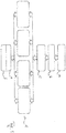
- Fig 1 shows a flow diagramm of the method of the invention for preparing a reconditioning of a damaged portion 2 ( Fig. 2 to Fig. 5 ) of a technical component 4 of an aircraft (not shown) and particularly of an integral component 4 namely a skin component 4, which is integrally formed of one material.
- the reconditioning is performed by adding an insert 6, which fills and/or bridges the damaged portion 2.
- the method comprises the steps of: Producing a 3D CAD repair model of the damaged portion by scanning (step a).
- a later step b is analysing the repair model and thus evaluating complexity of the damage and/or its reconditioning.
- a later step c is, as a function of the complexity, deciding between four different computer programs and computers (in different locations) - which still may be reached by the aircraft owner's or operator's repair departments via some data network or even via the internet, so that the required calculation power is available depending on the evaluated complexity of the damage and/or its reconditioning.
- Step c is, as a function of the complexity, deciding between four different computer programs to perform a following step d: analysing, by that decided computer program and computer, the repair model and thus dimensioning the reconditioning including the insert.
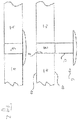
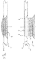
- Fig. 2 to Fig. 6 show diffent damages 2 as a result of a prior step (not shown) of working the damaged portion 2 by removing material from the damaged portion by means of CAM - such that the damaged portion is simplified (having walls 8 rectangular ( Fig. 2 to Fig. 4 ) to the flat outer surfaces 10 of the damaged aircraft skin 4, e.g.).
- the insert 6 is produced having at least one surface 12 complementary to the worked damage 8 (and thus to the CAD repair model after the working step; not shown).
- the damaged portion was prepared for a simpler shape of the insert (having the rectangular cylindrical walls 8 in Fig. 2 to Fig. 4 , e.g), into which the accordingly produced insert 6 fits (having the rectangular cylindrical walls 12 in Fig. 2 to Fig. 4 , e.g) in a complementary way, as to be seen in Fig. 2 to Fig. 6 .
- the insert 6 is produced having fastening structures 14, in the form of a pin or a rivet, integrated - as being one piece and of one material (made by 3d printing).
- the damaged portion 2 is worked, thus, creating a complementary structure 16 adopted to cooperate with the fastening structure 14.
- This again is made by removing material from the damaged portion 2 by means of CAM - and creating a complementary structure (a hole for the pin or rivet) adopted to cooperate with the fastening structure 14, namely to be inserted and locked a usual for a rivet and/or glued, e.g.
- the fastened insert 6 (respective lower drawing in Fig. 2 to Fig. 6 ), after inserting it (respective upper drawing in Fig. 2 to Fig. 6 ) into the damage 2, bridges and fills the damage 2 in a shape so that the damage 2 is reconditioned as, in particular, mechanically and aerodynamically required.
Landscapes
- Engineering & Computer Science (AREA)
- Physics & Mathematics (AREA)
- Theoretical Computer Science (AREA)
- Geometry (AREA)
- General Physics & Mathematics (AREA)
- Aviation & Aerospace Engineering (AREA)
- Computer Hardware Design (AREA)
- General Engineering & Computer Science (AREA)
- Evolutionary Computation (AREA)
- Transportation (AREA)
- Manufacturing & Machinery (AREA)
- Mathematical Optimization (AREA)
- Pure & Applied Mathematics (AREA)
- Mathematical Analysis (AREA)
- Automation & Control Theory (AREA)
- Computational Mathematics (AREA)
- Mechanical Engineering (AREA)
- Architecture (AREA)
- Software Systems (AREA)
Abstract
Description
- The invention is directed to: a method for preparing a reconditioning and to a method for reconditioning of a damaged portion of a component, particularly of an aircraft, by adding an insert, which fills and/or bridges the damaged portion and to such an insert therefor.
- As an example for a repair process having a high standard of security demands, the repair process of a damaged component of an aircraft presently comprises some burdens in particular for the owner or operator of the aircraft in terms of:
- Repair possibility as per Structure Repair Manual: for some areas neither is it is allowed to apply Allowable Damage Limits nor conventional skin repair, e.g. by doubler installation.
- High timely effort is required for producing the appropriate repair embodiment.
- The aircraft producer and the owner or operator of the aircraft have to store a lot of parts for repair on the stock, only by way of example metal doubler sheets in several dimensions and thicknesses, several stringer profiles, several frame profiles, several cross beam profiles, and several fastener types.
- Weight increases at use of the known doubler skin repair.
- Design rules for aircraft structure development form a margin for conventional repair solutions.
- These and other problems and disadvantages are addressed and solved by the
method fo claim 1 and the insert ofclaim 15 of the present invention. Preferred embodiments of the invention are disclosed in the dependent claims. - According to the invention, a method is disclosed for preparing a reconditioning of a damaged portion of a technical component, particularly of an aircraft and particularly of an integral component like a skin component, which in particular is integrally formed of one material or which, e.g., comprises a part which is integrally formed of one material and frames the component. The reconditioning is meant to be performed by adding an insert, which fills and/or bridges the damaged portion. The method comprises the steps of: Producing a 3D CAD repair model of the damaged portion by scanning (step a; for example optically, stereooptically, lenticular optically, by means of laser, infrared and/or with a Time of Flight camera). A later step b is analysing the repair model and thus evaluating complexity of the damage and/or its reconditioning. A later step c is, as a function of the complexity, deciding between at least two alternative means to perform at least a following step d (preferably according to an accordingly programmed decision matrix). And the later step d is analysing, by that decided means, the repair model and thus dimensioning the reconditioning including the insert.
- Accordingly, respective simpler repair preparation steps may be performed, e.g., by the aircraft owner's or operator's repair departments, whereas repair preparation steps, found to be more complex, which may require further specialized computer programs and/or computers, may be performed at accordingly spezialized firms or at the aircraft producer's own repair departments. Accordingly, the at least two alternative means may be at least two different computer programs and/or at least two computers (possibly in two different locations) - which still may be reached by the aircraft owner's or operator's repair departments via some data network or even via the internet, so that the required calculation power is available depending on the evaluated complexity of the damage and/or its reconditioning. At least one of the at least two alternative means may be according to a Standard Repair Manual and/or may even be a natural person's calculation.
- The method may be followed by the additional step e of producing the insert (in particular by means of CAM and/or by means of 3D printing possibly involving aluminum, titanium, steel and/or magnesium also as alloy and/or powder, and/or synthetic material including composites, possibly fibre-reinforced, possibly using short fibres, carbon fibres and/or glass fibres). The method may be completed to be a full method for reconditioning of the damaged portion by the following step f of inserting the insert into the damaged portion and fastening the insert to the component (possibly involving gluing, riveting, welding, brazing, soldering and/or pressing).
- The method may comprise the step of working the damaged portion (in particular by removing material from the damaged portion, in particular by means of CAM) - preferably such that the damaged portion and/or the CAD repair model (if updated) is simplified. Preferably, this working step is performed after the step (b) of analysing the repair model and thus evaluating complexity of the damage and/or its reconditioning - particularly, so that the working step will be based on the information, exactly how the CAD repair model may be simplified by this working step. After that working step, the 3D CAD repair model (now of the worked damaged portion) may be updated or newly be produced by scanning, e.g. by step a, (and/or the further steps are based on the priorly analysed (CAM) machine instruction informations for the working step, being CAD/CAM data with preference, according to which the damaged portion is simplified). Then, the repair model (now of the worked damaged portion) can be analysed, e.g. performing step b again, and thus the complexity of the damage and/or its reconditioning newly evaluated. After that, the method can be continued with the step (c) of deciding between the at least two alternative means as a function of the complexity - preferably being lower now as a result of the working step.
- For simpler performance and better results, step b of analysing the repair model and thus evaluating complexity of the damage and/or its reconditioning may be performed by comparing the repair model with a 3D CAD original model of the damaged portion in an original and undamaged status. This may be provided by the aircraft producer, as it exists there preferably in all required detail from designing and developing the aircraft. This step of analysing the repair model and thus evaluating complexity of the damage and/or its reconditioning can be performed by using dimensional and/or mechanical parameters and/or information of the CAD damage and/or original model.
- Step d (of analysing, by the decided means, the repair model and thus dimensioning the reconditioning including the insert) can be performed by calculating dimensional and/or mechanical parameters of the reconditioning including the insert - and provide for as many as possible or preferably all information required to produce the insert (in the later optional step e). Also step d, for simpler performance and better results, can be performed by comparing the repair model with a 3D CAD original model of the damaged portion in an original and undamaged status.
- At the optional step of producing the insert, the insert preferably is produced having at least one surface complementary to the damaged portion and/or the CAD repair model. This is particularly advantageous in combination with the step of working the damaged portion, where the portion may be prepared for a simpler shape of the insert, which will fit into the damaged portion (particularly its worked, simplified area) in a complementary way.
- And/or the insert can be produced having at least one fastening structure (a pin or a rivet, e.g.) integrated, in particular as being one piece and/or of one material (made by 3d printing, e.g.). Then the method preferably comprises the step of working the damaged portion and, thus, creating a complementary structure adopted to cooperate with the fastening structure. This again is preferably by removing material from the damaged portion and/or by means of CAM - and creating a complementary structure (like a hole for the pin) adopted to cooperate with the fastening structure.
- It is another aspect of the invention to provide an insert for filling and/or bridging a damaged portion for reconditioning of the damaged portion of a component, particularly of an aircraft, produced according to the method described so far - wherein the method may also be performed without step c: wherein then an insert (particularly with the integrated fastening structure) is prepared without deciding between at least two means to perform at least step d.
- Further advantages and embodiments are described in the following with regard to:
- Fig 1
- a flow diagramm of the method of the invention;
- Fig. 2
- a scematic sectional view of an insert inserted into a damaged portion;
- Fig. 3
- a scematic sectional view of an alternative insert inserted into a different damaged portion;
- Fig. 4
- a scematic sectional view of an alternative insert inserted into a different damaged portion;
- Fig. 5
- a scematic sectional view of an alternative insert inserted into a different damaged portion; and
- Fig. 6
- a scematic sectional view of an alternative insert inserted into a different damaged portion.
-
Fig 1 shows a flow diagramm of the method of the invention for preparing a reconditioning of a damaged portion 2 (Fig. 2 to Fig. 5 ) of atechnical component 4 of an aircraft (not shown) and particularly of anintegral component 4 namely askin component 4, which is integrally formed of one material. The reconditioning is performed by adding aninsert 6, which fills and/or bridges the damagedportion 2. - The method (
Fig. 1 ) comprises the steps of: Producing a 3D CAD repair model of the damaged portion by scanning (step a). A later step b is analysing the repair model and thus evaluating complexity of the damage and/or its reconditioning. A later step c is, as a function of the complexity, deciding between four different computer programs and computers (in different locations) - which still may be reached by the aircraft owner's or operator's repair departments via some data network or even via the internet, so that the required calculation power is available depending on the evaluated complexity of the damage and/or its reconditioning. - Step c is, as a function of the complexity, deciding between four different computer programs to perform a following step d: analysing, by that decided computer program and computer, the repair model and thus dimensioning the reconditioning including the insert.
- The method of
Fig. 1 is ended by the repair itself: step e of producing the insert by means of 3D printing; and step f of inserting the insert into the damaged portion and fastening the insert to the component. -
Fig. 2 to Fig. 6 show diffent damages 2 as a result of a prior step (not shown) of working the damagedportion 2 by removing material from the damaged portion by means of CAM - such that the damaged portion is simplified (havingwalls 8 rectangular (Fig. 2 to Fig. 4 ) to the flatouter surfaces 10 of the damagedaircraft skin 4, e.g.). - The
insert 6 is produced having at least onesurface 12 complementary to the worked damage 8 (and thus to the CAD repair model after the working step; not shown). In the step of working the damaged portion, the damaged portion was prepared for a simpler shape of the insert (having the rectangularcylindrical walls 8 inFig. 2 to Fig. 4 , e.g), into which the accordingly producedinsert 6 fits (having the rectangularcylindrical walls 12 inFig. 2 to Fig. 4 , e.g) in a complementary way, as to be seen inFig. 2 to Fig. 6 . - The
insert 6 is produced havingfastening structures 14, in the form of a pin or a rivet, integrated - as being one piece and of one material (made by 3d printing). The damagedportion 2 is worked, thus, creating acomplementary structure 16 adopted to cooperate with thefastening structure 14. This again is made by removing material from the damagedportion 2 by means of CAM - and creating a complementary structure (a hole for the pin or rivet) adopted to cooperate with thefastening structure 14, namely to be inserted and locked a usual for a rivet and/or glued, e.g. - Finally, the fastened insert 6 (respective lower drawing in
Fig. 2 to Fig. 6 ), after inserting it (respective upper drawing inFig. 2 to Fig. 6 ) into thedamage 2, bridges and fills thedamage 2 in a shape so that thedamage 2 is reconditioned as, in particular, mechanically and aerodynamically required.
Claims (14)
- Method for preparing a reconditioning of a damaged portion of a component, particularly of an aircraft, by adding an insert, which fills and/or bridges the damaged portion, comprising the steps of:a. Producing a 3D CAD repair model of the damaged portion by scanning;b. Analysing the repair model and thus evaluating complexity of the damage and/or its reconditioning;c. As a function of the complexity, deciding between at least two alternative means to perform at least a following step d:d. Analysing the repair model and thus dimensioning the reconditioning including the insert.
- Method according to claim 1, comprising the step of:- Working the damaged portion.
- Method according to claim 2, wherein step x is performed, such that the CAD repair model is simplified.
- Method according to claim 2 or 3, wherein step x is performed after step b and then repeating step b or step a and step b and then continuing with step c.
- Method according to one of the preceding claims, wherein step b is performed by comparing the repair model with a 3D CAD original model of the damaged portion in an original and undamaged status.
- Method according to one of the preceding claims, wherein step b is performed using dimensional and/or mechanical parameters of the CAD model.
- Method according to one of the preceding claims, wherein, in step c, the two alternative means are two different computer programs and/or computers.
- Method according to one of the preceding claims, wherein step d is performed by calculating dimensional and/or mechanical parameters of the reconditioning including the insert.
- Method according to one of the preceding claims, wherein step d is performed by comparing the repair model with a 3D CAD original model of the damaged portion in an original and undamaged status.
- Method according to one of the preceding claims, comprising the additional step of:e. Producing the insert.
- Method according to claim 10, wherein, in step e, the insert is produced having at least one surface complementary to the CAD repair model.
- Method according to claim 10 or 11, wherein, in step e, the insert is produced having at least one fastening structure integrated and wherein the method comprises the step:- Working the damaged portion and thus creating a complementary structure adopted to cooperate with the fastening structure creating a complementary structure adopted to cooperate with the fastening structure.
- Method according to one of the claims 10 to 12 for reconditioning the damaged portion, comprising the additional step of:f. Inserting the insert into the damaged portion and fastening the insert to the component.
- Insert for filling and/or bridging a damaged portion for reconditioning of the damaged portion of a component, particularly of an aircraft, produced according to one of the claims 10 to 12.
Priority Applications (4)
| Application Number | Priority Date | Filing Date | Title |
|---|---|---|---|
| ES16198503T ES2870479T3 (en) | 2016-11-11 | 2016-11-11 | Method for reconditioning a damaged part of a component and insert for it |
| EP16198503.1A EP3321189B1 (en) | 2016-11-11 | 2016-11-11 | Method for reconditioning of a damaged portion of a component and insert therefor |
| US15/697,691 US10507553B2 (en) | 2016-11-11 | 2017-09-07 | Method for reconditioning of a damaged portion of a component and insert therefor |
| CN201710912299.1A CN108069048A (en) | 2016-11-11 | 2017-09-29 | Method for the undamaged portion of remanufactured component and the insert for this method |
Applications Claiming Priority (1)
| Application Number | Priority Date | Filing Date | Title |
|---|---|---|---|
| EP16198503.1A EP3321189B1 (en) | 2016-11-11 | 2016-11-11 | Method for reconditioning of a damaged portion of a component and insert therefor |
Publications (2)
| Publication Number | Publication Date |
|---|---|
| EP3321189A1 true EP3321189A1 (en) | 2018-05-16 |
| EP3321189B1 EP3321189B1 (en) | 2021-03-03 |
Family
ID=57345703
Family Applications (1)
| Application Number | Title | Priority Date | Filing Date |
|---|---|---|---|
| EP16198503.1A Active EP3321189B1 (en) | 2016-11-11 | 2016-11-11 | Method for reconditioning of a damaged portion of a component and insert therefor |
Country Status (4)
| Country | Link |
|---|---|
| US (1) | US10507553B2 (en) |
| EP (1) | EP3321189B1 (en) |
| CN (1) | CN108069048A (en) |
| ES (1) | ES2870479T3 (en) |
Families Citing this family (3)
| Publication number | Priority date | Publication date | Assignee | Title |
|---|---|---|---|---|
| CN109808621A (en) * | 2019-03-25 | 2019-05-28 | 上海锦持汽车零部件再制造有限公司 | A kind of bumper reproducing method using adhesive |
| CN111038734B (en) * | 2019-12-27 | 2023-04-18 | 扬州大学 | Intelligent aviation restoration and supply system based on 3D printing |
| CN113665783B (en) * | 2021-10-09 | 2023-05-16 | 中国商用飞机有限责任公司 | Repair member for aircraft stringers and method of repairing an aircraft stringer |
Citations (6)
| Publication number | Priority date | Publication date | Assignee | Title |
|---|---|---|---|---|
| US20100161095A1 (en) * | 2008-12-19 | 2010-06-24 | The Boeing Company | Repairing Composite Structures |
| US20100274545A1 (en) * | 2009-04-27 | 2010-10-28 | The Boeing Company | Bonded Rework Simulation Tool |
| US20120198676A1 (en) * | 2011-02-03 | 2012-08-09 | Alstom Technology Ltd | Method for repairing or reconditioning a badly damaged component, in particular from the hot gas region of a gas turbine |
| US20120296460A1 (en) * | 2011-05-17 | 2012-11-22 | The Boeing Company | Bonded Rework Template System |
| US20160075028A1 (en) * | 2014-09-15 | 2016-03-17 | The Boeing Company | Methods and systems of repairing a structure |
| US20160263845A1 (en) * | 2013-11-28 | 2016-09-15 | Aircelle | Method for repairing sandwich panels made of composite materials involving the creation of a core or of a mould using stereolithography |
Family Cites Families (21)
| Publication number | Priority date | Publication date | Assignee | Title |
|---|---|---|---|---|
| FR812036A (en) | 1936-07-16 | 1937-04-28 | Variable area aircraft wing system | |
| DE10319494A1 (en) | 2003-04-30 | 2004-11-18 | Mtu Aero Engines Gmbh | Process for repairing and / or modifying components of a gas turbine |
| FR2856655A1 (en) | 2003-06-25 | 2004-12-31 | Erick Herzberger | RIGID WING WITH VARIABLE LIFT BY DEPLOYING A FLEXIBLE WING |
| SE528006C2 (en) * | 2004-12-23 | 2006-08-01 | Volvo Aero Corp | Static gas turbine component and method of repairing such component |
| FR2901246B1 (en) * | 2006-05-19 | 2008-06-20 | Airbus France Sas | METHOD FOR REPAIRING A DAMAGED ZONE OF AN AIRCRAFT FUSELAGE |
| DE102006033799A1 (en) | 2006-07-19 | 2008-01-24 | Mtu Aero Engines Gmbh | Method of repairing turbine blades |
| DE102006044555A1 (en) * | 2006-09-21 | 2008-04-03 | Mtu Aero Engines Gmbh | repair procedures |
| US8578579B2 (en) * | 2007-12-11 | 2013-11-12 | General Electric Company | System and method for adaptive machining |
| GB0810724D0 (en) | 2008-06-12 | 2008-07-16 | Airbus Uk Ltd | Slat assembly |
| ES2402257T3 (en) | 2009-10-30 | 2013-04-30 | Alstom Technology Ltd | Method to repair a component of a gas turbine |
| EP2317076B1 (en) | 2009-10-30 | 2018-02-14 | Ansaldo Energia IP UK Limited | A method for repairing a gas turbine component |
| EP2361720B1 (en) | 2010-02-22 | 2012-12-12 | Alstom Technology Ltd | Method for repairing and/or upgrading a component, especially of a gas turbine |
| FR2971993B1 (en) | 2011-02-25 | 2013-12-27 | Airbus Operations Sas | AIRCRAFT WITH REDUCED ENVIRONMENTAL IMPACT |
| US9085980B2 (en) | 2011-03-04 | 2015-07-21 | Honeywell International Inc. | Methods for repairing turbine components |
| FR2978070B1 (en) | 2011-07-22 | 2014-11-14 | Snecma | PROCESS FOR REPAIRING A TURBOMACHINE PIECE |
| DE102012013949A1 (en) | 2012-07-13 | 2014-01-30 | Rolls-Royce Deutschland Ltd & Co Kg | Repairing damaged portion of blade of gas turbine engine of aircraft, by digitizing blade damaged portion, comparing digitized data with predetermined data, inserting replacement parts and connecting replacement part with damaged portion |
| GB201301766D0 (en) * | 2013-01-31 | 2013-03-20 | Airbus Operations Ltd | Structural assembly joint |
| US9174312B2 (en) | 2013-03-12 | 2015-11-03 | Honeywell International Inc. | Methods for the repair of gas turbine engine components using additive manufacturing techniques |
| US20150047168A1 (en) | 2013-08-13 | 2015-02-19 | Allister William James | Repair chain for turbomachinery components using additive manufacturing technology |
| EP2873620B1 (en) | 2013-11-14 | 2018-05-16 | Airbus Operations GmbH | Repair method for fuselage components of aircraft or spacecraft |
| DE102014222159A1 (en) | 2014-10-30 | 2016-05-04 | MTU Aero Engines AG | Repair method and apparatus for generatively repairing a component |
-
2016
- 2016-11-11 EP EP16198503.1A patent/EP3321189B1/en active Active
- 2016-11-11 ES ES16198503T patent/ES2870479T3/en active Active
-
2017
- 2017-09-07 US US15/697,691 patent/US10507553B2/en active Active
- 2017-09-29 CN CN201710912299.1A patent/CN108069048A/en active Pending
Patent Citations (6)
| Publication number | Priority date | Publication date | Assignee | Title |
|---|---|---|---|---|
| US20100161095A1 (en) * | 2008-12-19 | 2010-06-24 | The Boeing Company | Repairing Composite Structures |
| US20100274545A1 (en) * | 2009-04-27 | 2010-10-28 | The Boeing Company | Bonded Rework Simulation Tool |
| US20120198676A1 (en) * | 2011-02-03 | 2012-08-09 | Alstom Technology Ltd | Method for repairing or reconditioning a badly damaged component, in particular from the hot gas region of a gas turbine |
| US20120296460A1 (en) * | 2011-05-17 | 2012-11-22 | The Boeing Company | Bonded Rework Template System |
| US20160263845A1 (en) * | 2013-11-28 | 2016-09-15 | Aircelle | Method for repairing sandwich panels made of composite materials involving the creation of a core or of a mould using stereolithography |
| US20160075028A1 (en) * | 2014-09-15 | 2016-03-17 | The Boeing Company | Methods and systems of repairing a structure |
Also Published As
| Publication number | Publication date |
|---|---|
| EP3321189B1 (en) | 2021-03-03 |
| US20180133850A1 (en) | 2018-05-17 |
| CN108069048A (en) | 2018-05-25 |
| ES2870479T3 (en) | 2021-10-27 |
| US10507553B2 (en) | 2019-12-17 |
Similar Documents
| Publication | Publication Date | Title |
|---|---|---|
| EP3321189A1 (en) | Method for reconditioning of a damaged portion of a component and insert therefor | |
| Wang et al. | Advanced 3D printing technologies for the aircraft industry: a fuzzy systematic approach for assessing the critical factors | |
| DE102007063608B4 (en) | Composite and fuselage cell section with such a composite | |
| Lindemann et al. | Towards a sustainable and economic selection of part candidates for additive manufacturing | |
| US8315837B2 (en) | Computer-aided method of obtaining a ply model of a composite component | |
| US8209838B2 (en) | Repairing composite structures | |
| EP2361720B1 (en) | Method for repairing and/or upgrading a component, especially of a gas turbine | |
| JP2018088244A (en) | Automated system and method for manufacturing aircraft junction parts | |
| DE102014222159A1 (en) | Repair method and apparatus for generatively repairing a component | |
| CH704448A1 (en) | A method of repairing or reconditioning of heavily damaged component, in particular from the hot gas area of a gas turbine. | |
| DE102007046478B4 (en) | Sheet metal laminate, in particular for fuselage skin panels for aircraft | |
| EP3211550A1 (en) | Method for producing a 3d cad model, use of the 3d cad model, computer program product and system for nc machining | |
| DE102007044662A1 (en) | Producing a tool for cutting sheet metals, comprises welding a cutter from a material of higher hardness on a base body from cast iron, and welding several welding seams next to each other to a buffer layer forming on a surface of the body | |
| DE102019113805B4 (en) | Method and device for predicting and / or reducing the deformation of a multi-part assembly | |
| Ghiasian et al. | A design modification system for additive manufacturing: Towards feasible geometry development | |
| US10376958B2 (en) | Removable support for additive manufacture | |
| DE69927479T2 (en) | Design and manufacture of objects | |
| KR20120021809A (en) | Ship hull welding shrinkage margin design automatiom method | |
| Butterfield et al. | An Integrated Approach to the Conceptual Development of Aircraft Structures Focusing on Manufacturing Simulation and Cost. | |
| WO2009129789A1 (en) | Method and device for automated position correction | |
| Zahedi et al. | Advanced airframe disassembly alternatives; an attempt to increase the afterlife value | |
| DE102005016557A1 (en) | Method for producing cooling insert for stator blades in gas turbines involves shaping outwardly curved and inwardly curved walls from single plate which is then bent about rear edge and welded along leading edge | |
| DE102022127199A1 (en) | Method for in-situ repair of an ultra-large one-piece casting | |
| Labordus et al. | Induction Welded Thermoplastic Overhang Panel. | |
| WO2024012759A1 (en) | Method and device for determining the geometric robustness of a multi-part assembly |
Legal Events
| Date | Code | Title | Description |
|---|---|---|---|
| PUAI | Public reference made under article 153(3) epc to a published international application that has entered the european phase |
Free format text: ORIGINAL CODE: 0009012 |
|
| STAA | Information on the status of an ep patent application or granted ep patent |
Free format text: STATUS: THE APPLICATION HAS BEEN PUBLISHED |
|
| AK | Designated contracting states |
Kind code of ref document: A1 Designated state(s): AL AT BE BG CH CY CZ DE DK EE ES FI FR GB GR HR HU IE IS IT LI LT LU LV MC MK MT NL NO PL PT RO RS SE SI SK SM TR |
|
| AX | Request for extension of the european patent |
Extension state: BA ME |
|
| STAA | Information on the status of an ep patent application or granted ep patent |
Free format text: STATUS: REQUEST FOR EXAMINATION WAS MADE |
|
| 17P | Request for examination filed |
Effective date: 20180827 |
|
| RBV | Designated contracting states (corrected) |
Designated state(s): AL AT BE BG CH CY CZ DE DK EE ES FI FR GB GR HR HU IE IS IT LI LT LU LV MC MK MT NL NO PL PT RO RS SE SI SK SM TR |
|
| STAA | Information on the status of an ep patent application or granted ep patent |
Free format text: STATUS: EXAMINATION IS IN PROGRESS |
|
| 17Q | First examination report despatched |
Effective date: 20200210 |
|
| REG | Reference to a national code |
Ref country code: DE Ref legal event code: R079 Ref document number: 602016053489 Country of ref document: DE Free format text: PREVIOUS MAIN CLASS: B64F0005400000 Ipc: G06F0030000000 |
|
| GRAP | Despatch of communication of intention to grant a patent |
Free format text: ORIGINAL CODE: EPIDOSNIGR1 |
|
| STAA | Information on the status of an ep patent application or granted ep patent |
Free format text: STATUS: GRANT OF PATENT IS INTENDED |
|
| RIC1 | Information provided on ipc code assigned before grant |
Ipc: G06F 30/15 20200101ALI20200918BHEP Ipc: B64F 5/40 20170101ALI20200918BHEP Ipc: G06F 30/00 20200101AFI20200918BHEP |
|
| INTG | Intention to grant announced |
Effective date: 20201013 |
|
| GRAS | Grant fee paid |
Free format text: ORIGINAL CODE: EPIDOSNIGR3 |
|
| STAA | Information on the status of an ep patent application or granted ep patent |
Free format text: STATUS: GRANT OF PATENT IS INTENDED |
|
| GRAA | (expected) grant |
Free format text: ORIGINAL CODE: 0009210 |
|
| STAA | Information on the status of an ep patent application or granted ep patent |
Free format text: STATUS: THE PATENT HAS BEEN GRANTED |
|
| AK | Designated contracting states |
Kind code of ref document: B1 Designated state(s): AL AT BE BG CH CY CZ DE DK EE ES FI FR GB GR HR HU IE IS IT LI LT LU LV MC MK MT NL NO PL PT RO RS SE SI SK SM TR |
|
| REG | Reference to a national code |
Ref country code: GB Ref legal event code: FG4D |
|
| REG | Reference to a national code |
Ref country code: AT Ref legal event code: REF Ref document number: 1368005 Country of ref document: AT Kind code of ref document: T Effective date: 20210315 Ref country code: CH Ref legal event code: EP |
|
| REG | Reference to a national code |
Ref country code: DE Ref legal event code: R096 Ref document number: 602016053489 Country of ref document: DE |
|
| REG | Reference to a national code |
Ref country code: IE Ref legal event code: FG4D |
|
| REG | Reference to a national code |
Ref country code: LT Ref legal event code: MG9D |
|
| PG25 | Lapsed in a contracting state [announced via postgrant information from national office to epo] |
Ref country code: NO Free format text: LAPSE BECAUSE OF FAILURE TO SUBMIT A TRANSLATION OF THE DESCRIPTION OR TO PAY THE FEE WITHIN THE PRESCRIBED TIME-LIMIT Effective date: 20210603 Ref country code: GR Free format text: LAPSE BECAUSE OF FAILURE TO SUBMIT A TRANSLATION OF THE DESCRIPTION OR TO PAY THE FEE WITHIN THE PRESCRIBED TIME-LIMIT Effective date: 20210604 Ref country code: HR Free format text: LAPSE BECAUSE OF FAILURE TO SUBMIT A TRANSLATION OF THE DESCRIPTION OR TO PAY THE FEE WITHIN THE PRESCRIBED TIME-LIMIT Effective date: 20210303 Ref country code: FI Free format text: LAPSE BECAUSE OF FAILURE TO SUBMIT A TRANSLATION OF THE DESCRIPTION OR TO PAY THE FEE WITHIN THE PRESCRIBED TIME-LIMIT Effective date: 20210303 Ref country code: BG Free format text: LAPSE BECAUSE OF FAILURE TO SUBMIT A TRANSLATION OF THE DESCRIPTION OR TO PAY THE FEE WITHIN THE PRESCRIBED TIME-LIMIT Effective date: 20210603 Ref country code: LT Free format text: LAPSE BECAUSE OF FAILURE TO SUBMIT A TRANSLATION OF THE DESCRIPTION OR TO PAY THE FEE WITHIN THE PRESCRIBED TIME-LIMIT Effective date: 20210303 |
|
| REG | Reference to a national code |
Ref country code: NL Ref legal event code: MP Effective date: 20210303 |
|
| REG | Reference to a national code |
Ref country code: AT Ref legal event code: MK05 Ref document number: 1368005 Country of ref document: AT Kind code of ref document: T Effective date: 20210303 |
|
| PG25 | Lapsed in a contracting state [announced via postgrant information from national office to epo] |
Ref country code: PL Free format text: LAPSE BECAUSE OF FAILURE TO SUBMIT A TRANSLATION OF THE DESCRIPTION OR TO PAY THE FEE WITHIN THE PRESCRIBED TIME-LIMIT Effective date: 20210303 Ref country code: RS Free format text: LAPSE BECAUSE OF FAILURE TO SUBMIT A TRANSLATION OF THE DESCRIPTION OR TO PAY THE FEE WITHIN THE PRESCRIBED TIME-LIMIT Effective date: 20210303 Ref country code: LV Free format text: LAPSE BECAUSE OF FAILURE TO SUBMIT A TRANSLATION OF THE DESCRIPTION OR TO PAY THE FEE WITHIN THE PRESCRIBED TIME-LIMIT Effective date: 20210303 Ref country code: SE Free format text: LAPSE BECAUSE OF FAILURE TO SUBMIT A TRANSLATION OF THE DESCRIPTION OR TO PAY THE FEE WITHIN THE PRESCRIBED TIME-LIMIT Effective date: 20210303 |
|
| PG25 | Lapsed in a contracting state [announced via postgrant information from national office to epo] |
Ref country code: NL Free format text: LAPSE BECAUSE OF FAILURE TO SUBMIT A TRANSLATION OF THE DESCRIPTION OR TO PAY THE FEE WITHIN THE PRESCRIBED TIME-LIMIT Effective date: 20210303 |
|
| REG | Reference to a national code |
Ref country code: ES Ref legal event code: FG2A Ref document number: 2870479 Country of ref document: ES Kind code of ref document: T3 Effective date: 20211027 |
|
| PG25 | Lapsed in a contracting state [announced via postgrant information from national office to epo] |
Ref country code: EE Free format text: LAPSE BECAUSE OF FAILURE TO SUBMIT A TRANSLATION OF THE DESCRIPTION OR TO PAY THE FEE WITHIN THE PRESCRIBED TIME-LIMIT Effective date: 20210303 Ref country code: CZ Free format text: LAPSE BECAUSE OF FAILURE TO SUBMIT A TRANSLATION OF THE DESCRIPTION OR TO PAY THE FEE WITHIN THE PRESCRIBED TIME-LIMIT Effective date: 20210303 Ref country code: SM Free format text: LAPSE BECAUSE OF FAILURE TO SUBMIT A TRANSLATION OF THE DESCRIPTION OR TO PAY THE FEE WITHIN THE PRESCRIBED TIME-LIMIT Effective date: 20210303 Ref country code: AT Free format text: LAPSE BECAUSE OF FAILURE TO SUBMIT A TRANSLATION OF THE DESCRIPTION OR TO PAY THE FEE WITHIN THE PRESCRIBED TIME-LIMIT Effective date: 20210303 |
|
| PG25 | Lapsed in a contracting state [announced via postgrant information from national office to epo] |
Ref country code: IS Free format text: LAPSE BECAUSE OF FAILURE TO SUBMIT A TRANSLATION OF THE DESCRIPTION OR TO PAY THE FEE WITHIN THE PRESCRIBED TIME-LIMIT Effective date: 20210703 Ref country code: PT Free format text: LAPSE BECAUSE OF FAILURE TO SUBMIT A TRANSLATION OF THE DESCRIPTION OR TO PAY THE FEE WITHIN THE PRESCRIBED TIME-LIMIT Effective date: 20210705 Ref country code: SK Free format text: LAPSE BECAUSE OF FAILURE TO SUBMIT A TRANSLATION OF THE DESCRIPTION OR TO PAY THE FEE WITHIN THE PRESCRIBED TIME-LIMIT Effective date: 20210303 Ref country code: RO Free format text: LAPSE BECAUSE OF FAILURE TO SUBMIT A TRANSLATION OF THE DESCRIPTION OR TO PAY THE FEE WITHIN THE PRESCRIBED TIME-LIMIT Effective date: 20210303 |
|
| REG | Reference to a national code |
Ref country code: DE Ref legal event code: R097 Ref document number: 602016053489 Country of ref document: DE |
|
| PLBE | No opposition filed within time limit |
Free format text: ORIGINAL CODE: 0009261 |
|
| STAA | Information on the status of an ep patent application or granted ep patent |
Free format text: STATUS: NO OPPOSITION FILED WITHIN TIME LIMIT |
|
| PG25 | Lapsed in a contracting state [announced via postgrant information from national office to epo] |
Ref country code: DK Free format text: LAPSE BECAUSE OF FAILURE TO SUBMIT A TRANSLATION OF THE DESCRIPTION OR TO PAY THE FEE WITHIN THE PRESCRIBED TIME-LIMIT Effective date: 20210303 Ref country code: AL Free format text: LAPSE BECAUSE OF FAILURE TO SUBMIT A TRANSLATION OF THE DESCRIPTION OR TO PAY THE FEE WITHIN THE PRESCRIBED TIME-LIMIT Effective date: 20210303 |
|
| 26N | No opposition filed |
Effective date: 20211206 |
|
| PG25 | Lapsed in a contracting state [announced via postgrant information from national office to epo] |
Ref country code: SI Free format text: LAPSE BECAUSE OF FAILURE TO SUBMIT A TRANSLATION OF THE DESCRIPTION OR TO PAY THE FEE WITHIN THE PRESCRIBED TIME-LIMIT Effective date: 20210303 |
|
| PG25 | Lapsed in a contracting state [announced via postgrant information from national office to epo] |
Ref country code: IT Free format text: LAPSE BECAUSE OF FAILURE TO SUBMIT A TRANSLATION OF THE DESCRIPTION OR TO PAY THE FEE WITHIN THE PRESCRIBED TIME-LIMIT Effective date: 20210303 |
|
| PG25 | Lapsed in a contracting state [announced via postgrant information from national office to epo] |
Ref country code: IS Free format text: LAPSE BECAUSE OF FAILURE TO SUBMIT A TRANSLATION OF THE DESCRIPTION OR TO PAY THE FEE WITHIN THE PRESCRIBED TIME-LIMIT Effective date: 20210703 |
|
| PG25 | Lapsed in a contracting state [announced via postgrant information from national office to epo] |
Ref country code: MC Free format text: LAPSE BECAUSE OF FAILURE TO SUBMIT A TRANSLATION OF THE DESCRIPTION OR TO PAY THE FEE WITHIN THE PRESCRIBED TIME-LIMIT Effective date: 20210303 |
|
| REG | Reference to a national code |
Ref country code: CH Ref legal event code: PL |
|
| PG25 | Lapsed in a contracting state [announced via postgrant information from national office to epo] |
Ref country code: LU Free format text: LAPSE BECAUSE OF NON-PAYMENT OF DUE FEES Effective date: 20211111 Ref country code: BE Free format text: LAPSE BECAUSE OF NON-PAYMENT OF DUE FEES Effective date: 20211130 |
|
| REG | Reference to a national code |
Ref country code: BE Ref legal event code: MM Effective date: 20211130 |
|
| PG25 | Lapsed in a contracting state [announced via postgrant information from national office to epo] |
Ref country code: IE Free format text: LAPSE BECAUSE OF NON-PAYMENT OF DUE FEES Effective date: 20211111 |
|
| PGFP | Annual fee paid to national office [announced via postgrant information from national office to epo] |
Ref country code: ES Payment date: 20230125 Year of fee payment: 7 |
|
| PG25 | Lapsed in a contracting state [announced via postgrant information from national office to epo] |
Ref country code: HU Free format text: LAPSE BECAUSE OF FAILURE TO SUBMIT A TRANSLATION OF THE DESCRIPTION OR TO PAY THE FEE WITHIN THE PRESCRIBED TIME-LIMIT; INVALID AB INITIO Effective date: 20161111 |
|
| PG25 | Lapsed in a contracting state [announced via postgrant information from national office to epo] |
Ref country code: CY Free format text: LAPSE BECAUSE OF FAILURE TO SUBMIT A TRANSLATION OF THE DESCRIPTION OR TO PAY THE FEE WITHIN THE PRESCRIBED TIME-LIMIT Effective date: 20210303 |
|
| PG25 | Lapsed in a contracting state [announced via postgrant information from national office to epo] |
Ref country code: LI Free format text: LAPSE BECAUSE OF NON-PAYMENT OF DUE FEES Effective date: 20220701 Ref country code: CH Free format text: LAPSE BECAUSE OF NON-PAYMENT OF DUE FEES Effective date: 20220701 |
|
| PGFP | Annual fee paid to national office [announced via postgrant information from national office to epo] |
Ref country code: GB Payment date: 20231123 Year of fee payment: 8 |
|
| PGFP | Annual fee paid to national office [announced via postgrant information from national office to epo] |
Ref country code: FR Payment date: 20231120 Year of fee payment: 8 Ref country code: DE Payment date: 20231121 Year of fee payment: 8 |
|
| PGFP | Annual fee paid to national office [announced via postgrant information from national office to epo] |
Ref country code: ES Payment date: 20240129 Year of fee payment: 8 |