EP3321130A1 - Method for reproducing a section of an image - Google Patents
Method for reproducing a section of an image Download PDFInfo
- Publication number
- EP3321130A1 EP3321130A1 EP17188983.5A EP17188983A EP3321130A1 EP 3321130 A1 EP3321130 A1 EP 3321130A1 EP 17188983 A EP17188983 A EP 17188983A EP 3321130 A1 EP3321130 A1 EP 3321130A1
- Authority
- EP
- European Patent Office
- Prior art keywords
- determined
- edge
- trailer
- motion vector
- image
- Prior art date
- Legal status (The legal status is an assumption and is not a legal conclusion. Google has not performed a legal analysis and makes no representation as to the accuracy of the status listed.)
- Granted
Links
- 238000000034 method Methods 0.000 title claims abstract description 64
- 239000013598 vector Substances 0.000 claims description 99
- 230000033001 locomotion Effects 0.000 claims description 97
- 239000011159 matrix material Substances 0.000 claims description 30
- 238000011156 evaluation Methods 0.000 claims description 17
- 238000001514 detection method Methods 0.000 claims description 13
- 230000006870 function Effects 0.000 description 14
- 230000007613 environmental effect Effects 0.000 description 12
- 238000004364 calculation method Methods 0.000 description 11
- 230000008901 benefit Effects 0.000 description 9
- 238000006073 displacement reaction Methods 0.000 description 8
- 239000000243 solution Substances 0.000 description 7
- 230000006978 adaptation Effects 0.000 description 4
- 238000007792 addition Methods 0.000 description 4
- 238000003708 edge detection Methods 0.000 description 4
- 230000003287 optical effect Effects 0.000 description 4
- 238000012545 processing Methods 0.000 description 4
- 230000000694 effects Effects 0.000 description 3
- 230000004886 head movement Effects 0.000 description 3
- 230000015572 biosynthetic process Effects 0.000 description 2
- 230000008859 change Effects 0.000 description 2
- 238000007796 conventional method Methods 0.000 description 2
- 230000008030 elimination Effects 0.000 description 2
- 238000003379 elimination reaction Methods 0.000 description 2
- 229920001817 Agar Polymers 0.000 description 1
- 230000001133 acceleration Effects 0.000 description 1
- 238000013459 approach Methods 0.000 description 1
- 230000006835 compression Effects 0.000 description 1
- 238000007906 compression Methods 0.000 description 1
- 230000001143 conditioned effect Effects 0.000 description 1
- 230000006735 deficit Effects 0.000 description 1
- 230000004069 differentiation Effects 0.000 description 1
- 239000000428 dust Substances 0.000 description 1
- 230000002996 emotional effect Effects 0.000 description 1
- 238000005562 fading Methods 0.000 description 1
- 239000000446 fuel Substances 0.000 description 1
- 238000003384 imaging method Methods 0.000 description 1
- 230000004807 localization Effects 0.000 description 1
- 230000008569 process Effects 0.000 description 1
- 230000000284 resting effect Effects 0.000 description 1
- 239000007921 spray Substances 0.000 description 1
- 230000001629 suppression Effects 0.000 description 1
- 230000002123 temporal effect Effects 0.000 description 1
- 230000007704 transition Effects 0.000 description 1
Images


Classifications
-
- B—PERFORMING OPERATIONS; TRANSPORTING
- B60—VEHICLES IN GENERAL
- B60R—VEHICLES, VEHICLE FITTINGS, OR VEHICLE PARTS, NOT OTHERWISE PROVIDED FOR
- B60R1/00—Optical viewing arrangements; Real-time viewing arrangements for drivers or passengers using optical image capturing systems, e.g. cameras or video systems specially adapted for use in or on vehicles
- B60R1/20—Real-time viewing arrangements for drivers or passengers using optical image capturing systems, e.g. cameras or video systems specially adapted for use in or on vehicles
- B60R1/22—Real-time viewing arrangements for drivers or passengers using optical image capturing systems, e.g. cameras or video systems specially adapted for use in or on vehicles for viewing an area outside the vehicle, e.g. the exterior of the vehicle
- B60R1/23—Real-time viewing arrangements for drivers or passengers using optical image capturing systems, e.g. cameras or video systems specially adapted for use in or on vehicles for viewing an area outside the vehicle, e.g. the exterior of the vehicle with a predetermined field of view
- B60R1/26—Real-time viewing arrangements for drivers or passengers using optical image capturing systems, e.g. cameras or video systems specially adapted for use in or on vehicles for viewing an area outside the vehicle, e.g. the exterior of the vehicle with a predetermined field of view to the rear of the vehicle
-
- G—PHYSICS
- G06—COMPUTING; CALCULATING OR COUNTING
- G06V—IMAGE OR VIDEO RECOGNITION OR UNDERSTANDING
- G06V10/00—Arrangements for image or video recognition or understanding
- G06V10/10—Image acquisition
- G06V10/12—Details of acquisition arrangements; Constructional details thereof
- G06V10/14—Optical characteristics of the device performing the acquisition or on the illumination arrangements
- G06V10/147—Details of sensors, e.g. sensor lenses
-
- G—PHYSICS
- G06—COMPUTING; CALCULATING OR COUNTING
- G06V—IMAGE OR VIDEO RECOGNITION OR UNDERSTANDING
- G06V20/00—Scenes; Scene-specific elements
- G06V20/50—Context or environment of the image
- G06V20/56—Context or environment of the image exterior to a vehicle by using sensors mounted on the vehicle
- G06V20/58—Recognition of moving objects or obstacles, e.g. vehicles or pedestrians; Recognition of traffic objects, e.g. traffic signs, traffic lights or roads
-
- B—PERFORMING OPERATIONS; TRANSPORTING
- B60—VEHICLES IN GENERAL
- B60R—VEHICLES, VEHICLE FITTINGS, OR VEHICLE PARTS, NOT OTHERWISE PROVIDED FOR
- B60R2300/00—Details of viewing arrangements using cameras and displays, specially adapted for use in a vehicle
- B60R2300/60—Details of viewing arrangements using cameras and displays, specially adapted for use in a vehicle characterised by monitoring and displaying vehicle exterior scenes from a transformed perspective
- B60R2300/602—Details of viewing arrangements using cameras and displays, specially adapted for use in a vehicle characterised by monitoring and displaying vehicle exterior scenes from a transformed perspective with an adjustable viewpoint
- B60R2300/605—Details of viewing arrangements using cameras and displays, specially adapted for use in a vehicle characterised by monitoring and displaying vehicle exterior scenes from a transformed perspective with an adjustable viewpoint the adjustment being automatic
-
- B—PERFORMING OPERATIONS; TRANSPORTING
- B60—VEHICLES IN GENERAL
- B60R—VEHICLES, VEHICLE FITTINGS, OR VEHICLE PARTS, NOT OTHERWISE PROVIDED FOR
- B60R2300/00—Details of viewing arrangements using cameras and displays, specially adapted for use in a vehicle
- B60R2300/80—Details of viewing arrangements using cameras and displays, specially adapted for use in a vehicle characterised by the intended use of the viewing arrangement
- B60R2300/8046—Details of viewing arrangements using cameras and displays, specially adapted for use in a vehicle characterised by the intended use of the viewing arrangement for replacing a rear-view mirror system
-
- B—PERFORMING OPERATIONS; TRANSPORTING
- B60—VEHICLES IN GENERAL
- B60R—VEHICLES, VEHICLE FITTINGS, OR VEHICLE PARTS, NOT OTHERWISE PROVIDED FOR
- B60R2300/00—Details of viewing arrangements using cameras and displays, specially adapted for use in a vehicle
- B60R2300/80—Details of viewing arrangements using cameras and displays, specially adapted for use in a vehicle characterised by the intended use of the viewing arrangement
- B60R2300/8066—Details of viewing arrangements using cameras and displays, specially adapted for use in a vehicle characterised by the intended use of the viewing arrangement for monitoring rearward traffic
-
- G—PHYSICS
- G06—COMPUTING; CALCULATING OR COUNTING
- G06V—IMAGE OR VIDEO RECOGNITION OR UNDERSTANDING
- G06V10/00—Arrangements for image or video recognition or understanding
- G06V10/40—Extraction of image or video features
- G06V10/44—Local feature extraction by analysis of parts of the pattern, e.g. by detecting edges, contours, loops, corners, strokes or intersections; Connectivity analysis, e.g. of connected components
- G06V10/443—Local feature extraction by analysis of parts of the pattern, e.g. by detecting edges, contours, loops, corners, strokes or intersections; Connectivity analysis, e.g. of connected components by matching or filtering
Definitions
- the present invention relates to a method for tracking an image detail of a camera image which is displayed on a monitor for replacement of an exterior mirror of a vehicle, in particular when cornering a vehicle consisting of a trailer and a trailer.
- a method for tracking an image section of a camera image of a vehicle and trailer trailer when cornering that is displayed on a monitor for replacing an exterior mirror of a vehicle is known.
- a monitor system is shown as a substitute for a rearview mirror in which the displayed image section of the movement of the head position of the driver is adjusted.
- the driver moves his head when the trailer turns "outwards" when cornering on a conventional rear-view mirror to keep an eye on the end of the trailer.
- the movement of the head position of the driver is detected.
- a reliable motion detection is required, which is generally expensive to implement. Head movements of the driver, which occur for reasons other than to change the visible for the driver in the conventional rearview image section, lead to unwanted adjustments of the image on the monitor.
- the position of a vertical edge of the trailer is determined from at least two consecutive camera images, and then the image section is tracked in accordance with the position of the vertical edge.
- Every second, third or generally n-th image is used for the evaluation, it also being possible alternately to skip a different number of images in order to achieve an effective n which lies between two natural numbers.
- the clock of the evaluation is adapted to the frame rate of the camera.
- differences in movement occur more conspicuously when using every second, third, etc. image. This can be particularly advantageous when driving slowly, with too large an evaluation can become too slow.
- the image section displayed on the monitor is tracked so that the rear edge of the trailer and the parts of the environment behind it are visible to the driver. This is done, for example, by compressing the lying between the vehicle and the rear edge of the trailer portion of the camera image, by linearly moving the image detail so that the edge is imaged approximately in the vehicle facing third of the monitor, by fading in an enlarged image detail, or in any other appropriate manner ,
- the vehicle is the towing vehicle of a team, it can be both a truck, a car, a tractor, bus, semitrailer or the like.
- a trailer the semi-trailer of a semitrailer is provided or a single or multi-axle trailer. If necessary, the team also has more than one trailer.
- the vertical edge is a significant edge for the rear end of the trailer. Edges can be reliably determined by known methods. For trailers with a high body, the trailer tail usually has a vertical edge. For trailers used to transport containers, the trailing edge of the container can be used as a significant edge. If such a trailer without resting container on the way, the lower edge located behind the trailer is used.
- At least one point is determined as an edge point.
- a motion vector and for this a reliability measure is determined.
- the measure of reliability serves to weight the vector higher or lower.
- the image section is not tracked directly using the motion vectors. Instead, the vectors are used to locate the trailer edge and then track the cutout according to the localized position.
- each tag has a vertical trailing edge that separates pixels of the tag from pixels of the environment.
- the line to be evaluated is chosen such that it intersects this edge.
- the line is in the first approach a straight line, but also a curved line is useful here, for example, in adaptation to the Vehicle-trailer configuration, camera characteristics, distortion or mounting bracket of the camera or the like.
- a preferred line is below the height of the loading area, such as in the area provided for the rear display elements such as brake light, reversing light, direction indicator, tail light, dangerous goods identification panel, underrun protection or the like. At this height there are definitely components of the trailer, even if there is no charge with a vertical edge.
- a line is selected that traverses most of the camera image or the entire camera image. This ensures that there is a crossing point between line and edge, regardless of the current position of the edge in the image.
- a shorter line is expediently selected, which is arranged approximately symmetrically to the previously determined edge point. This reduces the computational effort without reducing the probability of finding an edge point.
- edge point has a motion vector that is different from zero, this is an indication that the trailing edge is moving laterally, which necessitates tracking the image section.
- methods for determining the reliability of a motion vector are known. Here go the reliability of one-dimensional edge detection, motion detection, which is characterized by characteristics of the camera image such as contrast in terms of color or Brightness affected reliability of evaluation and / or other.
- the invention it is provided according to a variant to determine local extrema in derivatives of an image function along the line, and to calculate motion vectors at these points.
- the local extremes are an easy way to do that. Points belonging to the trailer on the line usually move very little relative to the camera. In the case of shadow movements, the movement generally occurs at a different speed or directional component than the background.
- As derivatives finite differences in the intensity function, the color spacing of adjacent pixels or other suitable evaluations of image functions are used. Local extrema in leads also occur due to noise.
- the image function is the gray scale of an image.
- any known point detection method is adapted to the one-dimensional case on the line. This has the advantage of providing more reliable results without requiring much extra computational effort.
- each motion vector is determined at several points of the line intersecting the vertical edge of the trailer. Then, for example, a discontinuity in the sequence of motion vectors determined along these points for the points may be determined as the location of the edge point.
- a similar effect is exploited as described above, but here is dispensed with the formation of the derivative, but only performed a comparison and detection of discontinuities. This reduces the required computational effort. But also other uses of the motion vectors determined here is meaningfully possible.
- the line intersecting the vertical edge is determined from the line used for the evaluation of the preceding camera image by shifting it by the motion vector determined for the preceding camera image.
- This has the advantage that the line is very likely to be where it intersects the edge since it is shifted according to the edge. This shift occurs in both the horizontal and vertical directions when the motion vector has the corresponding components.
- the use of short lines that do not cover the entire width of the camera image is thus made possible without the risk that the edge moves out of the region of the line.
- the line is not moved because the geometry of the trailer relative to the camera remains the same except for the trailer kink angle. That it does not go from the very left to the far right in the picture and therefore can be moved horizontally is one possibility.
- the line can also go from the very left to the far right.
- a given to a previous camera image or given by an environmental model motion vector is taken as a starting point, and determined therefrom, for example using an optical flow method via a 2x2 system of equations to the current camera image matching updated motion vector.
- a 2x2 system of equations opens up solve known manner without much effort.
- regularization takes place only in the vertical direction.
- Conventional regularization always regularizes in both directions.
- a determination of the vertical movement would also be useful, but this is often not reliable because the trailer trailing edge often looks the same at all vertical positions. Therefore, the search effort is saved according to the invention and given by the regularization a preferred vertical position, resulting for example from previous movements or from an environmental model.
- the motion vector is directly updated, but the matrix and from this the motion vector is determined by the solution of a 2x2 system of equations.
- a final matrix is further determined if the line to be evaluated, intersecting the rear edge of the tag, is a curved line.
- An easy way to get the measure of reliability is to use the condition number of the final matrix for it.
- the use of an updated motion vector determined on the basis of a motion vector associated with a previous camera image has the advantage that such an updated motion vector has a better Approximation is considered the unchanged previous motion vector.
- the motion vector search method is preferably initialized by previous motion vectors (BVi (t-1)) and / or by prior knowledge. It is also additionally or alternatively limited by previous motion vectors (BVi (t-1)) and / or by prior knowledge.
- the method according to the invention can advantageously also be used to determine the trailer edge for purposes other than tracking a picture detail. This is indicated in the independent method claim, are proposed to the corresponding embodiments described in the subclaims mentioned in the main claim.
- a control unit includes an edge point determination unit that performs image edge determination or feature determination, a motion vector determination unit, a reliability measure determination unit, a reliability measure evaluation unit, and an image detail tracking unit.
- the image detail tracking unit also has the function of a trailer edge determination unit. Function and advantages correspond to those described for the procedure.
- the invention relates to a camera monitor system for replacing the outside mirror in trucks, for example to save fuel costs.
- a tracking of the displayed on the screen to the outside is necessary with attached trailer in cornering to allow the driver to see the rear edge of his trailer instead of only on its side tarp.
- this need also results from the elimination possibility of changing the field of view by moving the head, as is the case with conventional mirrors.
- Frame-based edge detection techniques such as the so-called “Canny Edge Detection” are largely unsuitable for the given task, as many other edges are often included in the image. These edges include structure and printing of the truck trailer tarpaulin, lane markings on the road, visible foreign vehicles, other objects of the environment such. B. signage and structures. Edges of these objects can not be distinguished from the trailer trailing edge in every situation and with reasonable computational effort.
- Environmental reconstruction and object recognition methods such as the so-called "structure-from-motion” method therefore use the slightly shifted position of prominent object points in a plurality of images taken from different positions, for example from different cameras or when the camera is moving at successive times were recorded.
- the different shift of foreground and background objects is used. These occur due to different distances to the camera or due to independent object movement.
- a movement of the camera together with the truck, as well as a movement of the trailer regardless of its environment is given in typical driving situations.
- a robust detection, localization and differentiation of the trailer edge from other object edges in the image is still critical.
- the currently most important methods for determining the displacement can be roughly differentiated into: differential methods of optical flow (such as Lucas-Kanade, Horn-Schunck), motion estimation by pixel comparison (such as block matching, correlation), as well as methods for feature recognition, description and Match (SIFT, SURF, Shi & Tomasi, Harris, BRISK, FAST, LETTER, ORB).
- differential methods of optical flow such as Lucas-Kanade, Horn-Schunck
- motion estimation by pixel comparison such as block matching, correlation
- SIFT SIFT, SURF, Shi & Tomasi, Harris, BRISK, FAST, LETTER, ORB.
- the feature points of interest are detected.
- the detection of the horizontal displacement of the trailer trailing edge is essential.
- it is sufficient to detect any point of interest on that edge which is required for conventional applications vertical displacement would not be sufficient and therefore not recognized by typical methods.
- environmental models, or the like therefore, one or more horizontal or curved lines are determined that intersect the trailer trailing edge. In the simplest case, a horizontal line through the middle of the picture is sufficient here.
- distinctive points are identified by detection algorithms adapted to the one-dimensional problem.
- a motion vector is now determined using an adapted method, which indicates from which position in the previous image a point has moved to the current point of interest or to which position in the next image the current point of interest emotional.
- all methods can be adapted in a similar manner, whereby the adaptation principle remains the same:
- the search methods are not initialized with their standard vectors, but with vector estimates already known from previous images, environmental models, or the like. The search is usefully limited to their environment.
- the search in the vertical direction is even more limited or completely skipped, since a vertical edge, as is the case at the trailing edge, is very similar to any other of their positions and therefore an exact determination of the vertical displacement is often not possible anyway. Nevertheless, if a vertical search is performed, it is usefully regularized to allow a unique solution. This corresponds to a preference of vectors near the horizontal lines shifted by the vector estimates. For an algorithm following edge detection, a confidence measure is then determined for each vector indicating how unlikely it is that instead of the found vector, a different vector describes the true motion. This can z. B. on the accuracy of fit or on the gain in the accuracy of fit against similar candidate vectors are determined.
- the invention is adapted to detect the trailing edge of trailers in commercial vehicles or cars.
- the camera can be both a rear-facing camera for generating a rearview mirror replacement image and another suitable camera, such as a reversing camera.
- Fig. 1 shows a trailer 106 consisting of vehicle 103 and trailer 105.
- the environment 109 of the trailer 106 is shown here schematically as plane E1.
- the vehicle 103 is equipped with a control unit 110 for processing a camera image of a camera 111.
- the control unit 110 calculates a picture detail, which is displayed on a monitor 101 mounted in the interior of the vehicle 103, in accordance with the method according to the invention.
- This image section corresponds to what the driver of the vehicle 103 usually sees in his normal sitting position on the exterior mirrors 102 or what he can see there by turning or moving the head there.
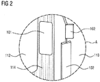
- the circled area A shows the transition area between windshield 112 and right side window 113 (not visible here). Area A is shown in the following figure from the perspective of the driver.
- Fig. 2 shows the monitor 101 and the outside mirror 102 from area A of Fig. 1 from the perspective of the driver in the right part of the interior of the vehicle 103.
- the monitor 101 is mounted on the A-pillar 114 of the driver's cab. Therefore, it does not cover any area of the windshield 112 or the side window 113. Through the side window 113 can be seen the two-part exterior mirror 102 on the right side of the vehicle 103.
- the outside mirror 102 covers part of the field of vision of the driver and is therefore covered by the driver Monitor 101 replaced. It is shown here only for clarity and comparison with the conventional solution.
- Fig. 3 shows the rear part of the trailer 105 with selected lines L1, L2, L3 for determining edge points KP1, KP2, KP3. These can also be further to the left, ie on the trailer, or further to the right, ie in the background.
- motions of individual pixels and an associated image function G (x) as well as their derivative G '(x) are shown.
- the line L1 is arranged in the lower area of the trailer 105, measured approximately at the height of a taillight unit 201 at about 1 m height from the roadway. In any case, the line L1 intersects the edge K5 irrespective of whether the trailer 105 is provided with a structure, container or other load forming the upper part of the rear edge K5 or not.
- edge point K1 The intersection of the line L1 with the edge K5 is the edge point K1.
- a further straight line L3 is located in the upper part of the load or the body and can therefore be evaluated well.
- Their intersection with the edge K5 is the edge point KP3.
- a curved line L2 is shown, with the edge point KP2.
- Their curvature is adapted to properties of the camera 111 and / or the geometry / nature of the trailer 105, but here only indicated schematically.
- the image function is the velocity G (x).
- G (x) In the right part, it is positive, corresponding to the movement of the pixels moving in the camera image 104, KB to the right pixels.
- G (x) In the right-hand area, G (x) is negative, corresponding to the surrounding pixels 109 moving to the left in the camera image KB, 104.
- a derivative is calculated only from an image function based on pixel gray values in the image, but not by a function based on motion vectors , Once the motion vectors are determined, the inventive method is completed.
- Fig. 4 shows on the left, in the middle and on the right each a monitor 101 with different image sections 104a, 104b of the camera image 104.
- the following description refers initially to the left part of Fig. 4 ,
- the image section 104a shown here shows all information relevant to the driver in this situation: the trailer 105 with its rear edge K5 and as object 108 of the environment 109 a following car.
- the edge K5 moves from that in the left part of Fig. 4 starting position corresponding to the motion vector BV from the image section 104a shown on the monitor 101 out into the image section 104b. This is in the middle part of the Fig. 4 shown in which the image section 104a is visible on the monitor 101, and the image section 104b is located to the right of the monitor, so is not visible to the driver.
- the image detail displayed on the monitor 101 is tracked according to the invention according to the value of the movement vector BV.
- the image section 104b is then displayed on the monitor 101, in which the rear edge K5 of the trailer 105 is again visible to the driver. With the edge K5 then the underlying parts of the environment 109 are then visible to the driver.
- the image section 104a which in this situation does not contain information relevant to the driver, is indicated here to the left of the monitor 101, that is to say not visible on the latter.
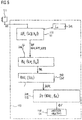
- Fig. 5 shows a control unit 110 according to the invention and a flow chart of the method according to the invention.
- the control unit 110 has an edge point determination unit 215, a motion vector determination unit 216, a reliability measure determination unit 217, a reliability measure evaluation unit 218, and a frame tracking unit 118.
- An output of the camera 111 is is connected to an input of the edge point determination unit 215.
- a first step S1 is executed. Its output is connected to an input of the motion vector determination unit 216.
- the edge point determination unit 215 is also connected to a memory 202.
- one or more lines Li are retrieved from the memory 202, which are used to determine the edge point KPi. It is also possible to store an optionally modified, updated, or new line Li in the memory 202. This is done, for example, from step S1, by loading from outside into the control unit 110, or in another suitable manner.
- the same is also done with the motion vector determination unit 216.
- the motion vectors of the previous image are stored in a memory and used for the initialization of the motion vector determination in the next image.
- the environmental or vehicle model information is then used for initialization in this memory.
- a second step S2 is executed, and its output is connected to the reliability measure determination unit 217.
- this step S31 is executed, its output is connected to the reliability measure unit 218.
- this step S32 is executed, its output is connected to the image detail tracking unit 118.
- a fourth step S4 is executed.
- the position KP, KP1, KP2, KP3, generally referred to as position KPi, of a vertical edge in the image is determined from at least one camera image KB (tj). Also in the feature matching method, the steps as in FIG Fig. 5 shown, all go through. The only difference is that feature points from two consecutive images are used in step S2 to determine the vectors. In the other embodiments, the feature points are determined only from a camera image.
- step S1 At least one line L1, L2, L3, Li intersecting this edge K5 is selected to determine the position of the edge K5 in step S101.
- the edge point KP1, KP2, KP3 is detected in step S102.
- a motion vector BV1, BV2, BV3 is determined from a plurality of temporally consecutive values KPi (Tj)) in the second step S2.
- the line L1, L2, L3, Li is preferably one in an in Fig. 5
- Prescribed fixed line Li stored in memory 202 of the vehicle 103.
- several lines Li are stored in the memory 202 and are adapted to different environmental conditions or vehicle configurations.
- different predetermined lines are provided for different trailer lengths, for different vehicle lengths, for trailers with multiple trailers, for trailers with high or low body, and the like.
- a line Li adapted, for example, to a new configuration of vehicle and trailer is stored in the memory 202 in order to be available in the future. This can be for the short-term next steps, but also for all future implementations of the procedure.
- a reliability measure BVV1, BVV2, BVV3 is determined for the motion vector BV1, BV2, BV3. If the reliability measure BVV1, BVV2, BVV3 is within a predetermined range, in particular if it is greater than a minimum value, a value BV is forwarded to step S4.
- the image section KBA is tracked according to the value of the motion vector BV in the fourth step S4.
- step S1 the line Li is selected in step S121, and in step S122, a plurality of points KPi-k on that line Li.
- step S123 Trailer 105 intersecting line Li each determines a motion vector BVi-k.
- the sequence of motion vectors BVi-k determined for these points KPi-k is then examined for discontinuities along the line Li. For this purpose, the difference ⁇ i-k of two successive motion vectors BVi-k, BVi- (k-1) is formed in step S124, and the maximum of the differences ⁇ i-k is formed in step S125.
- the point PKi at which the maximum lies, that is, the discontinuity occurs, is determined as an edge point PKi.
- the motion vector BVi belonging to this edge point PKi is used according to a variant instead of the motion vector BVi determined in step S2.
- Other known possibilities for determining the edge K5 can also be usefully used here.
- step S1 an image function G (x) along the line Li is evaluated to determine the position of the edge K5, see Fig. 3 , This will be in step S111 a line Li is selected, and in step S112 a derivative G '(x) is determined, ie the gray values along the line Li, and a derivative G' (x) is determined in step S113.
- the selection of the line Li is performed according to a first variant corresponding to the steps S101 or S121.
- step S114 local extrema G (KP1), G (KP1-1) are determined from G '(Li (x)). These correspond to the edge points KPi.
- the derivatives of the image function are taken along the horizontal lines L1, L2, L3. If necessary, these are first low-pass filtered for noise suppression. Derivatives are formed, for example, by finite differences in the intensity function or by color spacings of adjacent pixels in suitable color spaces. Likewise, it is possible to adapt a common method for feature recognition accordingly.
- step S2 A 2x2 equation system is used in step S2, that is to say for the determination of the motion vectors.
- the image intensity derivative vector b is then redetermined and the calculation is iteratively repeated a number of times.
- the details are known by the term "Lucas-Kanade method".
- this adaptation is preferably done as follows: A so-called “scale space” pyramid is calculated only along the horizontal line, that is, in one dimension rather than in two. This creates a two-dimensional scale space in which extremes can be searched by comparing the current value with only eight, rather than else, neighbor values. A subsequent elimination of edge points is not necessary. In this way if there is adequate environmental conditions, it is almost certain that a point will be found on the trailer's edge.
- the motion vector calculation in the second step S2 or in the step 123 takes place as follows:
- a differential optical flow method for example after BD Lucas and T. Kanade (1981) "An iterative image registration technique with an application to stereo vision", Proceedings of Imaging Understanding Workshop, p.121-130 , used.
- Fig. 9 shows a detail for determining the edge point KPi.
- the solution of the equation system does not differ from that known by the term "Lucas-Kanade method".
- the invention differs in this embodiment, as follows: First, the initialization is done with a vector estimate instead of a zero vector in the first interation, which is given by previous motion vectors or by a vehicle model. In some cases, the first resolution hierarchy levels can also be omitted. Second, the regularization perpendicular to the horizontal line. Thirdly, the 2x2 matrices MM or MF are updated instead of a recalculation. This update works as follows: M is an nx2 matrix, where n is the number of pixels used within an environment around the current edge point.
- MM M ⁇ T * M for the calculation of MF is also to be calculated at an adjacent edge position with intersecting environment, then instead of Two matrices MM_1, MM_r and MM_s are calculated, namely the matrix MM_1 from the environmental positions that can only be found in the vicinity of the first edge position KP1, the matrix MM_r from the environmental positions which are to be found exclusively in the vicinity of the second edge position KP2 and the matrix MM_s from the environmental positions which are to be found both in the vicinity of the first edge position KP1 and in the vicinity of the second edge position KP2, that is to say in the intersection.
- MM1 MM_1 + MM_s
- MM_r MM_s
- the method can be extended to more than two surrounding areas.
- MF Red * Reg + MM
- MM M ⁇ T * M
- MF Red * Reg + M ⁇ T * M
- BV MF ⁇ -1 + M ⁇ T * b.
- a 2x2 equation system is solved to update the calculated motion vector.
- L1, L3 it is possible with the aid of a Tikhonov regularizer restricted to the vertical direction to prefer vectors whose vertical component corresponds to that of the vector estimate.
- Curved line L2 is regularized in a correspondingly orthogonal direction by multiplying a rotation matrix.
- the condition number K of the final matrix is preferably used. Double computations at adjacent edge points KPi are avoided by merely updating the matrices instead of recalculating each other in overlapping neighborhoods for matrix determination. Renewed additions in the overlapping area are thus eliminated.
- the motion vector calculation in the second step S2 is carried out as follows: A pixel matching method, so-called block matching, is used. used. Block matching is commonly used in video compression. There are several search patterns for fast search, which typically start at the same place in the previous image KB ( tj-1 ) with the search. In the present case, the search is instead started for acceleration at the estimated position.
- the distance criterion used for example SAD, SSD, is slightly modified by addition of a punishment value. The punishment value corresponds to the distance to the vertical coordinate of the motion vector estimation. As fitting accuracy is typically just this distance criterion used.
- double calculations are preferably also avoided here by reuse of already made additions in the overlapping area.
- the motion vector calculation in the second step S2 is carried out as follows: A method for feature matching is used.
- Fig. 10 shows the display in the monitor 101 with the line L1 actually not shown there, which is here 1m above the ground, the level D1.
- the horizontal line L1 is typically curved in this view, and therefore also shown.
- Full search does not benefit from proper initialization. According to the invention, however, the comparison of feature points between two consecutive camera images KB ( tji ), KB ( tj ) is restricted locally. The search in this case is still limited to the environment of vector estimation. See Fig. 11 with the line L1 (t) at time t and hatches its environment used for vector estimation U (t). The line L1 (t + 1) and its surroundings U (t + 1) at a later time t + 1 is shifted in contrast.
- the detection of edge points KP1, KP2, KP3 in the second image is restricted to the vector line-shifted horizontal line L1 (t + 1) and optionally its environment.
- L1 (t + 1) is a temporarily shifted in the vertical direction Line L1 (t + 1), which, however, is not reused as a line in a later image, on the one hand, and is determined not from the determined motion vectors BVi, but from the vectors of, for example, an environment model.
- the motion vectors BVi represent the movement of the edge points KPi between time t and time t + 1. Accordingly, the method described above can be used here.
- a punishment value is added in the regularization because it is very far away from the shifted horizontal line L1 (t + 1).
- the addition of a punishment value to the feature distance criterion or descriptor value regularizes it.
- the distance between the best matching descriptors in the descriptor space is used in this case as fit.
- a fourth step S4 the camera image section KBA, corresponding to the position KP, KP1, KP2, KP3, tracks the vertical edge K5.
Abstract
Die vorliegende Erfindung betrifft ein Verfahren zur Nachführung eines auf einem Monitor (101) zum Ersatz eines Außenspiegels (102) eines Fahrzeugs (103) dargestellten Bildausschnitts (104a, 104b) eines Kamerabildes (104, KB) bei Kurvenfahrt eines aus dem Fahrzeug (103) und einem Anhänger (105) bestehenden Gespanns (106), sowie eine entsprechende Steuerungseinheit. Erfindungsgemäß wird
- die Position (KP, KP1, KP2, KP3) einer vertikalen Kante (K5) des Anhängers (105) aus zumindest zwei aufeinanderfolgenden Kamerabildern (KB(tj)) bestimmt, und
- der Bildausschnitt (104a, 104b) entsprechend der Position (KP, KP1, KP2, KP3) der vertikalen Kante (K5) nachgeführt.

the position (KP, KP1, KP2, KP3) of a vertical edge (K5) of the trailer (105) is determined from at least two consecutive camera images (KB (tj)), and
- The image section (104a, 104b) according to the position (KP, KP1, KP2, KP3) of the vertical edge (K5) tracked.
Description
Die vorliegende Erfindung betrifft ein Verfahren zur Nachführung eines Bildausschnitts eines Kamerabildes der auf einem Monitor zum Ersatz eines Außenspiegels eines Fahrzeugs dargestellten wird, insbesondere bei Kurvenfahrt eines aus dem Fahrzeug und einem Anhänger bestehenden Gespanns.The present invention relates to a method for tracking an image detail of a camera image which is displayed on a monitor for replacement of an exterior mirror of a vehicle, in particular when cornering a vehicle consisting of a trailer and a trailer.
Aus der
Es wird ein demgegenüber verbessertes Verfahren zur Nachführung des Bildausschnitts vorgeschlagen.An improved method for tracking the image section is proposed.
Erfindungsgemäß wird zunächst die Position einer vertikalen Kante des Anhängers aus zumindest zwei aufeinanderfolgenden Kamerabildern bestimmt, und anschließend der Bildausschnitt entsprechend der Position der vertikalen Kante nachgeführt. Dies hat den Vorteil, dass keine Detektion der Kopfbewegung des Fahrers erforderlich ist, auf dazu nötige Hardware in der Fahrerkabine kann verzichtet werden. Es wird erreicht, dass Kopfbewegungen des Fahrers, die aus anderen Gründen als der Blickwinkeländerung bezüglich des Außenspiegels erfolgen, keine unerwünschte Nachführung des Bildausschnitts zur Folge haben. Die Auswertung zumindest zweier aufeinanderfolgender Kamerabilder erhöht die Zuverlässigkeit der Kantenpositionsdetektion im Vergleich zur Auswertung eines Standbildes. Hier werden Bewegungen, die sich aus aufeinanderfolgenden Bildern erkennen lassen, berücksichtigt. Von Bild zu Bild unterschiedlich auftretende Schmutzeffekte, wie Bildrauschen, haben einen weniger starken Einfluss auf die Auswertung, da sie sich wegmitteln. Je mehr aufeinanderfolgende Bilder verwendet werden, umso besser können Bewegungseffekte genutzt werden um Fehldetektionen zu vermeiden, und umso besser werden Fehler weggemittelt. Es ist vorgesehen, unmittelbar aufeinanderfolgende Kamerabilder zu verwenden. Alternativ oder zusätzlich wird jedes zweite, dritte oder allgemein n-te Bild zur Auswertung herangezogen, wobei auch abwechselnd eine unterschiedliche Anzahl Bilder übersprungen werden kann, um ein effektives n zu erreichen, das zwischen zwei natürlichen Zahlen liegt. Zum einen wird dadurch der Takt der Auswertung an die Bildfrequenz der Kamera angepasst. Zum anderen treten Bewegungsunterschiede bei Verwendung jedes zweiten, dritten etc. Bildes auffälliger hervor. Dies kann insbesondere bei Langsamfahrt von Vorteil sein, wobei bei zu großem n die Auswertung zu langsam werden kann. Eine Anpassung auf die aktuell herrschenden Bedingungen ist hier sinnvoll. Die Nachführung des auf dem Monitor dargestellten Bildausschnitts erfolgt so, dass die hintere Kante des Anhängers sowie die hinter diesem befindlichen Teile der Umwelt für den Fahrer sichtbar sind. Dies erfolgt beispielsweise durch Stauchen des zwischen Fahrzeug und hinterer Kante des Anhängers liegenden Bereichs des Kamerabildes, durch lineares Verschieben des Bildausschnitts, so dass die Kante etwa im dem Fahrzeug zugewandten Drittel des Monitors abgebildet wird, durch Einblenden eines vergrößerten Bildausschnitts, oder auf andere geeignete Weise.According to the invention, firstly the position of a vertical edge of the trailer is determined from at least two consecutive camera images, and then the image section is tracked in accordance with the position of the vertical edge. This has the advantage that no detection of the head movement of the driver is required on the necessary hardware in the Driver's cab can be omitted. It is achieved that head movements of the driver, which occur for reasons other than the change in the viewing angle with respect to the exterior mirror, do not result in unwanted tracking of the image section. The evaluation of at least two consecutive camera images increases the reliability of the edge position detection in comparison to the evaluation of a still image. Here, movements that can be seen from successive images are taken into account. From image to image differently occurring dirt effects, such as image noise, have a less strong influence on the evaluation, since they move away. The more successive images are used, the better the motion effects can be used to avoid misdetections, and the better the errors are averaged out. It is intended to use immediately consecutive camera images. Alternatively or additionally, every second, third or generally n-th image is used for the evaluation, it also being possible alternately to skip a different number of images in order to achieve an effective n which lies between two natural numbers. On the one hand, the clock of the evaluation is adapted to the frame rate of the camera. On the other hand, differences in movement occur more conspicuously when using every second, third, etc. image. This can be particularly advantageous when driving slowly, with too large an evaluation can become too slow. An adaptation to the currently prevailing conditions makes sense here. The image section displayed on the monitor is tracked so that the rear edge of the trailer and the parts of the environment behind it are visible to the driver. This is done, for example, by compressing the lying between the vehicle and the rear edge of the trailer portion of the camera image, by linearly moving the image detail so that the edge is imaged approximately in the vehicle facing third of the monitor, by fading in an enlarged image detail, or in any other appropriate manner ,
Das Fahrzeug ist das Zugfahrzeug eines Gespanns, es kann sowohl ein LKW, ein PKW, ein Traktor, Bus, Sattelschlepper oder ähnliches sein. Als Anhänger ist der Auflieger eines Sattelzugs vorgesehen oder ein ein- oder mehrachsiger Anhänger. Gegebenenfalls weist das Gespann auch mehr als einen Anhänger auf. Die vertikale Kante ist eine für das hintere Ende des Anhängers signifikante Kante. Kanten können mit bekannten Verfahren zuverlässig bestimmt werden. Bei Anhängern mit hohem Aufbau weist das hintere Ende des Anhängers üblicherweise eine senkrechte Kante auf. Bei Anhängern, die zum Transport von Containern genutzt werden, ist als signifikante Kante die hintere Kante des Containers nutzbar. Ist ein solcher Anhänger ohne aufliegenden Container unterwegs, wird die im unteren Bereich befindliche Hinterkante des Anhängers genutzt.The vehicle is the towing vehicle of a team, it can be both a truck, a car, a tractor, bus, semitrailer or the like. As a trailer, the semi-trailer of a semitrailer is provided or a single or multi-axle trailer. If necessary, the team also has more than one trailer. The vertical edge is a significant edge for the rear end of the trailer. Edges can be reliably determined by known methods. For trailers with a high body, the trailer tail usually has a vertical edge. For trailers used to transport containers, the trailing edge of the container can be used as a significant edge. If such a trailer without resting container on the way, the lower edge located behind the trailer is used.
Gemäß der Erfindung wird entlang zumindest einer Linie, die die vertikale Kante des Anhängers schneidet, zumindest ein Punkt als Kantenpunkt bestimmt. Zu diesem Kantenpunkt wird ein Bewegungsvektor und für diesen ein Verlässlichkeitsmaß bestimmt. Das Verlässlichkeitsmaß dient dazu, den Vektor höher oder niedriger zu gewichten. Der Bildausschnitt wird nicht direkt anhand der Bewegungsvektoren nachgeführt. Stattdessen werden die Vektoren verwendet, um die Anhängerkante zu lokalisieren und dann den Ausschnitt entsprechend der lokalisierten Position nachzuführen. Dies hat den Vorteil, dass die Auswertung vereinfacht und beschleunigt wird, da nicht das gesamte Bild auszuwerten ist, sondern die Auswertung auf einen relevanten Bereich des Bildes beschränkt ist, hier den Bereich um die Linie herum oder die entsprechenden Bildbereiche im Fall von mehreren Linien. Statt einer zweidimensionalen Auswertung, die das gesamte Kamerabild betrifft, wird die Auswertung auf einen oder mehrere quasi eindimensionale Bereiche beschränkt. Im Allgemeinen weist jeder Anhänger eine vertikale hintere Kante auf, die Bildpunkte des Anhängers von Bildpunkten der Umgebung trennt. Die auszuwertende Linie wird so gewählt, dass sie diese Kante schneidet. Die Linie ist im ersten Ansatz eine Gerade, aber auch eine gekrümmte Linie ist hier sinnvoll möglich, beispielsweise in Anpassung auf die Fahrzeug-Anhänger-Konfiguration, Kameraeigenschaften, Verzerrung oder Montagewinkel der Kamera oder ähnliches. Eine bevorzugte Linie liegt unterhalb der Höhe der Ladefläche, etwa im für die rückwärtigen Anzeigeelemente wie Bremslicht, Rückfahrleuchte, Richtungsanzeiger, Rücklicht, Gefahrgutkennzeichnungstafel, Unterfahrschutz oder ähnliches vorgesehenen Bereich. Auf dieser Höhe sind auf jeden Fall Bestandteile des Anhängers vorhanden, auch wenn keine Ladung mit senkrechter Kante vorhanden sein sollte. Insbesondere bei Anhängern mit festem Aufbau oder Containern ist es sinnvoll, zusätzlich oder sogar ausschließlich eine Linie auszuwerten, die sich auf Höhe des Aufbaus oder Containers befindet. In dieser Höhe ist der Kontrast zwischen Anhänger und Umgebung oft größer als in niedriger Höhe, und daher besser auswertbar. Auch ist die mögliche Beeinträchtigung des Kamerabildes durch aufgewirbelten Staub, Spritzwasser oder dergleichen auf dieser Höhe geringer, was die Verlässlichkeit der Auswertung erhöht.According to the invention, along at least one line intersecting the vertical edge of the trailer, at least one point is determined as an edge point. For this edge point, a motion vector and for this a reliability measure is determined. The measure of reliability serves to weight the vector higher or lower. The image section is not tracked directly using the motion vectors. Instead, the vectors are used to locate the trailer edge and then track the cutout according to the localized position. This has the advantage that the evaluation is simplified and accelerated because not the entire image is to be evaluated, but the evaluation is limited to a relevant area of the image, here the area around the line or the corresponding image areas in the case of several lines. Instead of a two-dimensional evaluation, which relates to the entire camera image, the evaluation is limited to one or more quasi one-dimensional areas. Generally, each tag has a vertical trailing edge that separates pixels of the tag from pixels of the environment. The line to be evaluated is chosen such that it intersects this edge. The line is in the first approach a straight line, but also a curved line is useful here, for example, in adaptation to the Vehicle-trailer configuration, camera characteristics, distortion or mounting bracket of the camera or the like. A preferred line is below the height of the loading area, such as in the area provided for the rear display elements such as brake light, reversing light, direction indicator, tail light, dangerous goods identification panel, underrun protection or the like. At this height there are definitely components of the trailer, even if there is no charge with a vertical edge. Especially for trailers with fixed body or containers, it makes sense to evaluate additionally or even exclusively a line that is at the height of the body or container. At this altitude, the contrast between the trailer and the environment is often greater than at low altitude, making it easier to interpret. Also, the possible impairment of the camera image by whirling dust, spray or the like at this level is lower, which increases the reliability of the evaluation.
Zumindest zu Beginn des Verfahrens wird als die die vertikale Kante kreuzende Linie eine Linie gewählt, die einen Großteil des Kamerabildes oder das ganze Kamerabild durchläuft. Dies stellt sicher, dass ein Kreuzungspunkt von Linie und Kante vorhanden ist, unabhängig von der aktuellen Position der Kante im Bild. Im späteren Verlauf des Verfahrens wird sinnvollerweise eine kürzere Linie gewählt, die in etwa symmetrisch zu dem zuvor bestimmten Kantenpunkt angeordnet ist. Dies verringert den Rechenaufwand ohne die Wahrscheinlichkeit, einen Kantenpunkt zu finden, zu reduzieren.At least at the beginning of the process, as the line crossing the vertical edge, a line is selected that traverses most of the camera image or the entire camera image. This ensures that there is a crossing point between line and edge, regardless of the current position of the edge in the image. In the later course of the method, a shorter line is expediently selected, which is arranged approximately symmetrically to the previously determined edge point. This reduces the computational effort without reducing the probability of finding an edge point.
Weist der Kantenpunkt einen von Null verschiedenen Bewegungsvektor auf, so ist dies ein Anzeichen dafür, dass die hintere Kante sich seitlich bewegt, was eine Nachführung des Bildausschnitts erforderlich macht. Aus der Bildverarbeitung sind Verfahren zur Bestimmung der Zuverlässigkeit eines Bewegungsvektors bekannt. Hier gehen die Verlässlichkeit der eindimensionalen Kantendetektion, der Bewegungsdetektion, die durch Eigenschaften des Kamerabildes wie Kontrast bezüglich Farbe oder Helligkeit beeinflusste Verlässlichkeit der Auswertung und/oder anderes ein. Bekannt aus der Literatur sind ähnliche Verfahren, beispielsweise beim "Differenziellen Optischen Fluss" die Konditionszahl des 2x2 Gleichungssystems, beim Block-Matching die SAD oder SSD, die sich aus dem Vergleich der Bildblöcke ergibt, oder beim Merkmalsabgleich der Abstand zwischen den Deskriptoren der zusammenpassenden Merkmalspunkte. Liegt das Verlässlichkeitsmaß oberhalb eines vorgegebenen Werts, so wird davon ausgegangen, dass der Bewegungsvektor nicht etwa aufgrund einer Fehldetektion von Null verschieden ist, sondern eine tatsächlich vorhandene Bewegung anzeigt. Die oben genannten, aus der Literatur bekannten Verlässlichkeitsmaße ähnlicher Verfahren sind genaugenommen Maße für die Unverlässlichkeit: Wenn sie Null sind, ist die Verlässlichkeit maximal und kleiner als Null können sie aufgrund der Berechnung nicht werden. Ein Verlässlichkeitsmaß erhält man dann beispielsweise durch simple Invertierung, also Bildung von 1/x.If the edge point has a motion vector that is different from zero, this is an indication that the trailing edge is moving laterally, which necessitates tracking the image section. From image processing, methods for determining the reliability of a motion vector are known. Here go the reliability of one-dimensional edge detection, motion detection, which is characterized by characteristics of the camera image such as contrast in terms of color or Brightness affected reliability of evaluation and / or other. Similar methods are known from the literature, for example the condition number of the 2x2 equation system in the case of "differential optical flow", the block matching the SAD or SSD resulting from the comparison of the image blocks, or the distance between the descriptors of the matching feature points in the case of feature matching , If the reliability measure is above a predetermined value, then it is assumed that the motion vector is not different from zero due to a misdetection, for example, but rather indicates an actually existing movement. The above-mentioned reliability measures of similar methods known from the literature are, strictly speaking, measures of unreliability: if they are zero, the reliability is maximum and less than zero they can not become due to the calculation. A measure of reliability is then obtained, for example, by simple inversion, ie formation of 1 / x.
Erfindungsgemäß ist nach einer Variante vorgesehen, lokale Extrema in Ableitungen einer Bildfunktion entlang der Linie zu bestimmen, und an diesen Punkten Bewegungsvektoren zu berechnen. Die lokalen Extrema sind dazu eine einfache Möglichkeit. Zum Anhänger gehörende Punkte auf der Linie bewegen sich üblicherweise sehr wenig relativ zur Kamera. Im Fall von Schattenbewegungen erfolgt die Bewegung im Allgemeinen mit anderer Geschwindigkeit oder anderer Richtungskomponente als für den Hintergrund. Als Ableitungen werden finite Differenzen in der Intensitätsfunktion, der Farbabstand benachbarter Pixel oder andere geeignete Auswertungen von Bildfunktionen verwendet. Lokale Extrema in Ableitungen treten auch durch Rauschen hervorgerufen auf. Bei der Bildfunktion handelt es sich um die Grauwerte eines Bildes. Gemäß einer anderen erfindungsgemäßen Variante wird ein beliebiges bekanntes Punktdetektionsverfahren auf den eindimensionalen Fall auf der Linie angepasst. Dies hat den Vorteil, verlässlichere Ergebnisse zu liefern, ohne großen zusätzlichen Berechnungsaufwand zu erfordern.According to the invention, it is provided according to a variant to determine local extrema in derivatives of an image function along the line, and to calculate motion vectors at these points. The local extremes are an easy way to do that. Points belonging to the trailer on the line usually move very little relative to the camera. In the case of shadow movements, the movement generally occurs at a different speed or directional component than the background. As derivatives, finite differences in the intensity function, the color spacing of adjacent pixels or other suitable evaluations of image functions are used. Local extrema in leads also occur due to noise. The image function is the gray scale of an image. According to another variant of the invention, any known point detection method is adapted to the one-dimensional case on the line. This has the advantage of providing more reliable results without requiring much extra computational effort.
Erfindungsgemäß ist vorgesehen, dass zu mehreren Punkten der die vertikale Kante des Anhängers schneidenden Linie jeweils ein Bewegungsvektor bestimmt wird. Dann kann beispielsweise eine Unstetigkeit in der Abfolge der zu diesen Punkten bestimmten Bewegungsvektoren entlang der Linie als Ort des Kantenpunkts bestimmt werden. Hier wird ein ähnlicher Effekt ausgenutzt wie zuvor beschrieben, allerdings wird hier auf die Bildung der Ableitung verzichtet, sondern lediglich ein Vergleich und Detektion von Unstetigkeiten durchgeführt. Dies reduziert den erforderlichen Rechenaufwand. Aber auch andere Verwendungen der hier bestimmten Bewegungsvektoren ist sinnvoll möglich.According to the invention, it is provided that in each case one motion vector is determined at several points of the line intersecting the vertical edge of the trailer. Then, for example, a discontinuity in the sequence of motion vectors determined along these points for the points may be determined as the location of the edge point. Here, a similar effect is exploited as described above, but here is dispensed with the formation of the derivative, but only performed a comparison and detection of discontinuities. This reduces the required computational effort. But also other uses of the motion vectors determined here is meaningfully possible.
Die die vertikale Kante schneidende Linie wird erfindungsgemäß aus der zur Auswertung des vorangegangenen Kamerabildes verwendeten Linie bestimmt, indem diese um den zum vorangegangenen Kamerabild bestimmten Bewegungsvektor verschoben wird. Dies hat den Vorteil, dass die Linie mit hoher Wahrscheinlichkeit dort liegt, wo sie die Kante schneidet, da sie entsprechend der Kante verschoben wird. Diese Verschiebung erfolgt sowohl in horizontaler als auch in vertikaler Richtung, wenn der Bewegungsvektor die entsprechenden Komponenten aufweist. Insbesondere die Verwendung von kurzen Linien, die nicht die gesamte Breite des Kamerabildes abdecken, wird damit ermöglicht ohne die Gefahr, dass sich die Kante aus dem Bereich der Linie heraus bewegt. In vertikaler Richtung wird die Linie nicht bewegt, da die Geometrie des Gespanns relativ zur Kamera abgesehen vom Anhänger-Knickwinkel immer gleich bleibt. Dass sie nicht von ganz links nach ganz rechts im Bild geht und daher horizontal bewegt werden kann, ist eine Möglichkeit. Die Linie kann ebenso von ganz links nach ganz rechts gehen.According to the invention, the line intersecting the vertical edge is determined from the line used for the evaluation of the preceding camera image by shifting it by the motion vector determined for the preceding camera image. This has the advantage that the line is very likely to be where it intersects the edge since it is shifted according to the edge. This shift occurs in both the horizontal and vertical directions when the motion vector has the corresponding components. In particular, the use of short lines that do not cover the entire width of the camera image is thus made possible without the risk that the edge moves out of the region of the line. In the vertical direction, the line is not moved because the geometry of the trailer relative to the camera remains the same except for the trailer kink angle. That it does not go from the very left to the far right in the picture and therefore can be moved horizontally is one possibility. The line can also go from the very left to the far right.
Vorteilhafterweise wird ein zu einem vorhergehenden Kamerabild bestimmter oder durch ein Umweltmodell gegebener Bewegungsvektor als Ausgangspunkt genommen, und daraus beispielsweise mit Hilfe eines Optischen-Fluss-Verfahrens über eine 2x2-Gleichungssystem ein zum aktuellen Kamerabild passender aktualisierter Bewegungsvektor bestimmt. Ein 2x2-Gleichungssystem lässt sich auf bekannte Weise ohne großen Aufwand lösen. Es gibt mehrere Verfahren zur Bestimmung der Bewegungsvektoren. Eines ist das differenzielle Lukas-Kanade-Verfahren, das mit den 2x2-Gleichungssystemen arbeitet. Ebenso können aber auch Pixel- oder Merkmalsvergleichsverfahren verwendet werden.Advantageously, a given to a previous camera image or given by an environmental model motion vector is taken as a starting point, and determined therefrom, for example using an optical flow method via a 2x2 system of equations to the current camera image matching updated motion vector. A 2x2 system of equations opens up solve known manner without much effort. There are several methods for determining the motion vectors. One is the differential Lukas-Kanade method, which works with the 2x2 equation systems. Likewise, however, pixel or feature comparison methods can also be used.
Es ist weiterhin vorgesehen, durch Addieren einer Regularisierungs-Matrix zur 2x2-Matrix des Gleichungssystems eine regularisierte Matrix zu bestimmen. Dadurch wird die Bewegung hauptsächlich in horizontaler Richtung gesucht, das heißt der Richtung, die eine verlässliche Bewegungsvektorbestimmung zulässt. Das entscheidende im Falle der Regularisierung ist, dass nur in vertikaler Richtung regularisiert wird. In herkömmlichen Regularisierungsverfahren wird immer in beide Richtungen regularisiert. Es wäre auch eine Bestimmung der vertikalen Bewegung ebenso nützlich, jedoch ist dies oft nicht zuverlässig möglich, da die Anhängerhinterkante oft an allen vertikalen Positionen gleich aussieht. Daher wird der Suchaufwand erfindungsgemäß erspart und durch die Regularisierung eine bevorzugte vertikale Position vorgegeben, die sich etwa aus vorherigen Bewegungen oder aus einem Umweltmodell ergibt. Hier wird nicht der Bewegungsvektor direkt, sondern die Matrix aktualisiert und daraus dann durch die Lösung eines 2x2-Gleichungssystems der Bewegungsvektor bestimmt.It is further provided to determine a regularized matrix by adding a regularization matrix to the 2x2 matrix of the equation system. Thereby, the motion is searched mainly in the horizontal direction, that is the direction that allows a reliable motion vector determination. The decisive factor in the case of regularization is that regularization takes place only in the vertical direction. Conventional regularization always regularizes in both directions. A determination of the vertical movement would also be useful, but this is often not reliable because the trailer trailing edge often looks the same at all vertical positions. Therefore, the search effort is saved according to the invention and given by the regularization a preferred vertical position, resulting for example from previous movements or from an environmental model. Here, not the motion vector is directly updated, but the matrix and from this the motion vector is determined by the solution of a 2x2 system of equations.
Durch Multiplikation der Regularisierungsmatrix mit einer Rotations-Matrix wird weiterhin eine finale Matrix bestimmt, falls es sich bei der auszuwertenden, die hintere Kante des Anhängers schneidenden Linie um eine gekrümmte Linie handelt.By multiplying the regularization matrix with a rotation matrix, a final matrix is further determined if the line to be evaluated, intersecting the rear edge of the tag, is a curved line.
Eine einfache Möglichkeit, das Verlässlichkeitsmaß zu erhalten, besteht darin, die Konditionszahl der finalen Matrix dafür zu verwenden. Die Verwendung eines aktualisierten Bewegungsvektors, der auf Basis eines Bewegungsvektors bestimmt wurde, der zu einem vorhergehenden Kamerabild gehört, hat den Vorteil, dass ein solcher aktualisierter Bewegungsvektor eine bessere Approximation ist als der ungeänderte vorhergehende Bewegungsvektor.An easy way to get the measure of reliability is to use the condition number of the final matrix for it. The use of an updated motion vector determined on the basis of a motion vector associated with a previous camera image has the advantage that such an updated motion vector has a better Approximation is considered the unchanged previous motion vector.
Das Bewegungsvektorsuchverfahren wird vorzugsweise durch vorherige Bewegungsvektoren (BVi(t-1)) und/oder durch Vorwissen initialisiert. Es wird ebenfalls zusätzlich oder alternativ durch vorherige Bewegungsvektoren (BVi(t-1)) und/oder durch Vorwissen beschränkt.The motion vector search method is preferably initialized by previous motion vectors (BVi (t-1)) and / or by prior knowledge. It is also additionally or alternatively limited by previous motion vectors (BVi (t-1)) and / or by prior knowledge.
Das erfindungsgemäße Verfahren kann vorteilhafterweise auch dazu verwendet werden, die Anhängerkante zu anderen Zwecken als dem der Nachführung eines Bildausschnitts zu bestimmen. Dies ist im nebengeordneten Verfahrensanspruch angegeben, zu dem entsprechende Ausgestaltungen wie in den zum Hauptanspruch genannten Unteransprüchen beschrieben vorgeschlagen werden.The method according to the invention can advantageously also be used to determine the trailer edge for purposes other than tracking a picture detail. This is indicated in the independent method claim, are proposed to the corresponding embodiments described in the subclaims mentioned in the main claim.
Eine erfindungsgemäße Steuerungseinheit weist eine Kantenpunkt-Bestimmungs-Einheit auf, die eine Bildkantenbestimmung oder Merkmalsbestimmung durchführt, eine Bewegungsvektor-Bestimmungs-Einheit, eine Verlässlichkeitsmaß-Bestimmungs-Einheit, eine Verlässlichkeitsmaß-Bewertungs-Einheit und eine Bildausschnitt-Nachführungs-Einheit. Die Bildausschnitt-Nachführungs-Einheit weist auch die Funktion einer Anhängerkantenbestimmungseinheit auf. Funktion und Vorteile entsprechen denjenigen, die zum Verfahren beschrieben sind.A control unit according to the present invention includes an edge point determination unit that performs image edge determination or feature determination, a motion vector determination unit, a reliability measure determination unit, a reliability measure evaluation unit, and an image detail tracking unit. The image detail tracking unit also has the function of a trailer edge determination unit. Function and advantages correspond to those described for the procedure.
In anderen Worten betrifft die Erfindung ein Kamera-MonitorSystem zum Ersatz des Außenspiegels in LKWs, um beispielsweise Treibstoffkosten einzusparen. Eine Nachführung des auf dem Display angezeigten Bildausschnittes nach außen ist bei angehängtem Anhänger in Kurvenfahrten notwendig, um dem Fahrer die Sicht auf die Hinterkante seines Anhängers anstatt nur auf dessen Seitenplane zu ermöglichen. Insbesondere beim Rangieren ergibt sich diese Notwendigkeit auch durch die wegfallende Möglichkeit, durch Bewegung des Kopfes das Sichtfeld zu verändern, wie dies bei herkömmlichen Spiegeln der Fall ist.In other words, the invention relates to a camera monitor system for replacing the outside mirror in trucks, for example to save fuel costs. A tracking of the displayed on the screen to the outside is necessary with attached trailer in cornering to allow the driver to see the rear edge of his trailer instead of only on its side tarp. In particular, when maneuvering, this need also results from the elimination possibility of changing the field of view by moving the head, as is the case with conventional mirrors.
Für die Nachführung wird eine automatische Erkennung der aktuellen x-/y-Position der vertikalen Hinterkante des Anhängers im Bild vorgeschlagen. Da sich die Hinterkante über eine gewisse Länge erstreckt, gelten für die y-Position gewisse Vorgaben, zum Beispiel soll sie einen Meter über dem Boden erkannt werden. Zu beachten ist hierbei, dass eine Vielzahl verschiedener Anhänger verwendet werden können, und dass die Rechenleistung des Bildverarbeitungssystems sehr stark eingeschränkt ist.For tracking, an automatic detection of the current x / y position of the vertical trailing edge of the trailer is suggested in the image. Since the trailing edge extends over a certain length, certain specifications apply to the y position, for example, it should be recognized one meter above the ground. It should be noted that a variety of different trailers can be used, and that the processing power of the image processing system is very limited.
Auf Einzelbildern basierende Kantendetektionsverfahren, wie die sogenannte "Canny Edge Detection", sind für die gegebene Aufgabe größtenteils ungeeignet, da oftmals viele weitere Kanten im Bild enthalten sind. Diese Kanten sind unter anderem Struktur und Bedruckung der LKW-Anhängerplane, Fahrspurmarkierungen auf der Straße, sichtbare Fremdfahrzeuge, weitere Objekte der Umgebung wie z. B. Beschilderung und Bauwerke. Kanten dieser Objekte sind nicht in jeder Situation und mit überschaubarem Rechenaufwand von der Anhängerhinterkante zu unterscheiden.Frame-based edge detection techniques, such as the so-called "Canny Edge Detection", are largely unsuitable for the given task, as many other edges are often included in the image. These edges include structure and printing of the truck trailer tarpaulin, lane markings on the road, visible foreign vehicles, other objects of the environment such. B. signage and structures. Edges of these objects can not be distinguished from the trailer trailing edge in every situation and with reasonable computational effort.
Umgebungsrekonstruktions- und Objekterkennungsverfahren wie zum Beispiel das sogenannte "Structure-From-Motion"-Verfahren bedienen sich daher der leicht verschobenen Position von markanten Objektpunkten in mehreren, aus unterschiedlichen Positionen aufgenommenen Bildern, die beispielsweise von unterschiedlichen Kameras stammen oder bei bewegter Kamera zu aufeinanderfolgenden Zeitpunkten aufgezeichnet wurden. Hierbei wird insbesondere die unterschiedliche Verschiebung von Vordergrund- und Hintergrundobjekten genutzt. Diese treten aufgrund von unterschiedlichen Abständen zur Kamera oder aufgrund von unabhängiger Objektbewegung auf.Environmental reconstruction and object recognition methods such as the so-called "structure-from-motion" method therefore use the slightly shifted position of prominent object points in a plurality of images taken from different positions, for example from different cameras or when the camera is moving at successive times were recorded. In particular, the different shift of foreground and background objects is used. These occur due to different distances to the camera or due to independent object movement.
Sowohl eine Bewegung der Kamera zusammen mit dem LKW, als auch eine Bewegung des Anhängers unabhängig von seiner Umgebung ist bei typischen Fahrsituationen gegeben. Kritisch ist jedoch nach wie vor eine robuste Erkennung, Lokalisierung und Unterscheidung der Anhängerkante von anderen Objektkanten im Bild.A movement of the camera together with the truck, as well as a movement of the trailer regardless of its environment is given in typical driving situations. However, a robust detection, localization and differentiation of the trailer edge from other object edges in the image is still critical.
Die derzeit wichtigsten Verfahren zur Bestimmung der Verschiebung können grob unterschieden werden in: Differenzielle Verfahren des optischen Flusses (wie Lucas-Kanade, Horn-Schunck), Bewegungsschätzung mittels Pixelvergleich (wie Block-Matching, Korrelation), sowie Verfahren zur Merkmalserkennung, -beschreibung und -abgleichung (SIFT, SURF, Shi & Tomasi, Harris, BRISK, FAST, BRIEF, ORB).The currently most important methods for determining the displacement can be roughly differentiated into: differential methods of optical flow (such as Lucas-Kanade, Horn-Schunck), motion estimation by pixel comparison (such as block matching, correlation), as well as methods for feature recognition, description and Match (SIFT, SURF, Shi & Tomasi, Harris, BRISK, FAST, LETTER, ORB).
Sowohl die Erkennung von Punkten von Interesse im Bild, als auch die Berechnung des jeweiligen Verschiebungsvektors sind in herkömmlichen Verfahren dafür ausgelegt und optimiert, innerhalb eines bestimmten Flächenbereichs des Bildes Verschiebungen möglichst exakt zu berechnen. Dies funktioniert besonders gut an Eckpunkten von Objekten, weniger gut dagegen an Kanten, da die Verschiebung in Richtung der Kante nicht robust erkannt werden kann. Verschiebungen werden daher von den herkömmlichen Verfahren vorzugsweise an Eckpunkten berechnet. Bei der vorliegenden Problemstellung ist es jedoch notwendig, die Verschiebung der Anhängerhinterkante zu erkennen, wobei insbesondere die horizontale Verschiebung benötigt wird. Bei der vertikalen Verschiebung, also in Richtung der Kante, können jedoch Kompromisse in Kauf genommen werden. Für diese Aufgabe sind die oben genannten Verfahren auch nicht sehr effizient bezüglich des Rechenaufwandes, da stets innerhalb einer zweidimensionalen Region des Bildes gesucht werden muss. Die daraus unter anderem resultierende Genauigkeit in vertikaler Richtung kann von nachfolgenden Algorithmen zumeist nicht gewinnbringend genutzt werden. Ebenso kann Vorwissen, das beispielsweise aus vorherigen Bildern oder Umweltmodellen bekannt ist, nicht genutzt werden um den Rechenaufwand zu verringern.Both the recognition of points of interest in the image, as well as the calculation of the respective displacement vector are designed and optimized in conventional methods for calculating shifts as accurately as possible within a certain area of the image. This works especially well on vertices of objects, but not so well on edges, as the shift towards the edge can not be robustly detected. Shifts are therefore calculated by the conventional methods, preferably at vertices. In the present problem, however, it is necessary to detect the displacement of the trailer trailing edge, in particular, the horizontal displacement is required. In the vertical displacement, ie in the direction of the edge, however, compromises can be accepted. For this task, the above methods are also not very efficient in terms of computational effort, since it is always necessary to search within a two-dimensional region of the image. Among other things, the resulting accuracy in the vertical direction can not be used profitably by subsequent algorithms. Likewise, prior knowledge, which is known for example from previous images or environmental models, can not be used to reduce the computational effort.
In einem ersten Schritt gemäß der Erfindung erfolgt eine Detektion der Merkmalspunkte von Interesse. Für die gegebene Problemstellung ist insbesondere die Erkennung der horizontalen Verschiebung der Anhängerhinterkante wesentlich. Hierfür genügt es, einen beliebigen Punkt von Interesse auf dieser Kante zu erkennen, der für herkömmliche Anwendungen aufgrund der benötigten vertikalen Verschiebung nicht ausreichen würde und daher von typischen Verfahren nicht erkannt wird. Mit Hilfe von Vorwissen, Umweltmodellen, oder ähnlichem, werden daher eine oder mehrere horizontale oder gekrümmte Linien bestimmt, die die Anhängerhinterkante schneiden. Im einfachsten Fall genügt hier eine horizontale Gerade durch die Mitte des Bildes. Auf dieser werden durch auf das eindimensionale Problem angepasste Detektionsalgorithmen markante Punkte identifiziert.In a first step according to the invention, the feature points of interest are detected. For the given problem, in particular the detection of the horizontal displacement of the trailer trailing edge is essential. For this, it is sufficient to detect any point of interest on that edge, which is required for conventional applications vertical displacement would not be sufficient and therefore not recognized by typical methods. With the aid of prior knowledge, environmental models, or the like, therefore, one or more horizontal or curved lines are determined that intersect the trailer trailing edge. In the simplest case, a horizontal line through the middle of the picture is sufficient here. On this, distinctive points are identified by detection algorithms adapted to the one-dimensional problem.
In einem zweiten Schritt gemäß der Erfindung werden zugehörige Bewegungsvektoren berechnet. Für jeden bestimmten Punkt von Interesse wird nun mit Hilfe eines angepassten Verfahrens ein Bewegungsvektor bestimmt, der angibt, von welcher Position im vorhergehenden Bild sich ein Punkt an den aktuellen Punkt von Interesse bewegt hat beziehungsweise zu welcher Position im nächsten Bild sich der aktuelle Punkt von Interesse bewegt. Hierzu können wahlweise alle Verfahren (differentielle, Pixelvergleich, Merkmalsabgleich) in ähnlicher Art und Weise angepasst werden, wobei das Anpassungsprinzip gleich bleibt: Zuerst werden die Suchverfahren nicht mit ihren Standardvektoren, sondern mit bereits aus vorherigen Bildern, Umweltmodellen, oder ähnlichem bekannten Vektorabschätzungen initialisiert. Die Suche wird hierbei sinnvollerweise auf deren Umgebung beschränkt. Optional wird die Suche in vertikaler Richtung noch stärker eingeschränkt oder vollständig übersprungen, da eine vertikale Kante, wie sie bei der Anhängerhinterkante vorliegt, jeder anderen ihrer Positionen sehr stark ähnelt und daher eine exakte Bestimmung der vertikalen Verschiebung oftmals ohnehin nicht möglich ist. Falls dennoch eine vertikale Suche durchgeführt wird, wird diese sinnvollerweise regularisiert, um eine eindeutige Lösung zu ermöglichen. Dies entspricht einer Bevorzugung von Vektoren nahe der um die Vektorabschätzungen verschobenen horizontalen Linien. Für einen auf die Kantendetektion nachfolgenden Algorithmus wird sodann ein Verlässlichkeitsmaß für jeden Vektor bestimmt, der angibt, wie unwahrscheinlich es ist, dass statt dem gefundenen Vektor ein davon abweichender Vektor die wahre Bewegung beschreibt. Dieses kann z. B. über die Passgenauigkeit oder über den Gewinn in der Passgenauigkeit gegenüber ähnlichen Kandidatenvektoren ermittelt werden. Falls die Bestimmung der Verlässlichkeit mit dem vorgesehenen Verfahren nicht möglich oder sinnvoll ist, wird hier auch auf die entsprechende Methode eines anderen Verfahrens (zum Beispiel das sogenannte Block-Matching) zurückgegriffen. Schließlich kann durch die näher beieinander liegenden Merkmalspunkte (aufgrund der Bestimmung entlang nur einer Dimension) oftmals durch geschickte Vermeidung von Doppelberechnungen Rechenaufwand eingespart werden.In a second step according to the invention, associated motion vectors are calculated. For each particular point of interest, a motion vector is now determined using an adapted method, which indicates from which position in the previous image a point has moved to the current point of interest or to which position in the next image the current point of interest emotional. Optionally, all methods (differential, pixel comparison, feature matching) can be adapted in a similar manner, whereby the adaptation principle remains the same: First, the search methods are not initialized with their standard vectors, but with vector estimates already known from previous images, environmental models, or the like. The search is usefully limited to their environment. Optionally, the search in the vertical direction is even more limited or completely skipped, since a vertical edge, as is the case at the trailing edge, is very similar to any other of their positions and therefore an exact determination of the vertical displacement is often not possible anyway. Nevertheless, if a vertical search is performed, it is usefully regularized to allow a unique solution. This corresponds to a preference of vectors near the horizontal lines shifted by the vector estimates. For an algorithm following edge detection, a confidence measure is then determined for each vector indicating how unlikely it is that instead of the found vector, a different vector describes the true motion. This can z. B. on the accuracy of fit or on the gain in the accuracy of fit against similar candidate vectors are determined. If the determination of the reliability with the proposed method is not possible or meaningful, the corresponding method of another method (for example the so-called block matching) is also used here. Finally, due to the closer together lying feature points (due to the determination along only one dimension) often computational effort can be saved by skillful avoidance of double calculations.
Die Erfindung ist dazu geeignet, die Hinterkante von Anhängern bei Nutzfahrzeugen oder PKWs zu erkennen. Dabei kann die Kamera sowohl eine nach hinten gerichtete Kamera zum Erzeugen eines Rückspiegel-Ersatz-Bildes sein als auch eine andere geeignete Kamera, wie beispielsweise eine Rückfahrkamera.The invention is adapted to detect the trailing edge of trailers in commercial vehicles or cars. In this case, the camera can be both a rear-facing camera for generating a rearview mirror replacement image and another suitable camera, such as a reversing camera.
Vorteile der Erfindung sind unter anderem:
- Es wird ein deutlich geringerer Rechenaufwand bei der Detektion von Kantenpunkten benötigt. Es werden häufiger korrekte Kantenpunkte auf der Anhängerkante gefunden. Bei der Berechnung von Bewegungsvektoren ist ein deutlich geringerer Rechenaufwand erforderlich. Aufgrund von geeigneter Initialisierung treten weniger Ausreißer und schlecht bestimmte Bewegungsvektoren auf. Mittels der Regularisierung wird eine eindeutige und bessere Lösung des für Merkmalspunkte auf Kanten schlecht konditionierten Vektorbestimmungsproblems erzielt. Das Verlässlichkeitsmaß kann auch bei nachfolgenden, hier nicht beschriebenen Algorithmen genutzt werden, was dort zu besseren Resultaten führt.
- There is a significantly lower computational effort in the detection of edge points needed. Correct edge points are often found on the trailer edge. When calculating motion vectors, significantly less computational effort is required. Due to proper initialization, fewer outliers and poorly determined motion vectors occur. By means of the regularization, a clear and better solution of the vector determination problem badly conditioned for feature points on edges is achieved. The reliability measure can also be used in subsequent algorithms not described here, which leads to better results there.
Weitere Vorteile und Varianten der Erfindung sind auch der folgenden Beschreibung von Ausführungsbeispielen anhand der Figuren zu entnehmen. Dabei zeigen:
- Fig. 1
- Gespann in dem ein erfindungsgemäßes Verfahren implementiert ist,
- Fig. 2
- Monitor und Außenspiegel aus
Fig.1 aus Sicht des Fahrers, - Fig. 3
- hinterer Teil des Anhängers mit beispielhafter Bildfunktion,
- Fig. 4
- Monitor mit unterschiedlichen Bildausschnitten,
- Fig. 5
- erfindungsgemäße Steuerungseinheit und Flussdiagramm des erfindungsgemäßen Verfahrens,
- Fig. 6
- Bestimmung des Kantenpunkts aus vorgegebener Linie,
- Fig. 7
- Bestimmung des Kantenpunkts aus Differenzen,
- Fig. 8
- Bestimmung des Kantenpunkts aus Ableitung,
- Fig. 9
- Detail zur Bestimmung des Kantenpunkts,
- Fig. 10
- Monitorbild gemäß einer Ausführungsform,
- Fig. 11
- Berechnung des Bewegungsvektors gemäß Ausführungsform der
Fig.10 .
- Fig. 1
- Group in which a method according to the invention is implemented,
- Fig. 2
- Monitor and outside mirrors off
Fig.1 from the perspective of the driver, - Fig. 3
- rear part of the trailer with exemplary image function,
- Fig. 4
- Monitor with different image sections,
- Fig. 5
- Control unit according to the invention and flow chart of the method according to the invention,
- Fig. 6
- Determination of the edge point from a given line,
- Fig. 7
- Determination of the edge point from differences,
- Fig. 8
- Determination of the edge point from derivative,
- Fig. 9
- Detail for determining the edge point,
- Fig. 10
- Monitor image according to an embodiment,
- Fig. 11
- Calculation of the motion vector according to the embodiment of the
Figure 10 ,
In der unteren Hälfte der
Bei Kurvenfahrt des Gespanns 106 wandert die Kante K5 von der im linken Teil der
Der auf dem Monitor 101 dargestellte Bildausschnitt wird erfindungsgemäß entsprechend dem Wert des Bewegungsvektors BV nachgeführt. Wie im rechten Teil der
Gemäß einer Variante wird gleiches auch mit der Bewegungsvektor-Bestimmungs-Einheit 216 gemacht. Hier werden in einem Speicher die Bewegungsvektoren des vorherigen Bildes gespeichert und für die Initialisierung der Bewegungsvektorbestimmung im nächsten Bild verwendet. In einer alternativen Variante werden dann in diesem Speicher auch die Umwelt- bzw. Fahrzeugmodellinformationen für die Initialisierung verwendet.According to a variant, the same is also done with the motion
In der Bewegungsvektor-Bestimmungs-Einheit 216 wird ein zweiter Schritt S2 ausgeführt, ihr Ausgang ist mit der Verlässlichkeitsmaß-Bestimmungs-Einheit 217 verbunden. In dieser wird ein Schritt S31 ausgeführt, ihr Ausgang ist verbunden mit der Verlässlichkeitsmaß-Bewertungs-Einheit 218. In dieser wird Schritt S32 ausgeführt, ihr Ausgang ist mit der Bildausschnitt-Nachführungs-Einheit 118 verbunden. In dieser wird ein vierter Schritt S4 ausgeführt.In the motion
Im ersten Schritt S1 wird die Position KP, KP1, KP2, KP3, allgemein als Position KPi bezeichnet, einer vertikalen Kante im Bild aus zumindest einem Kamerabild KB (tj) bestimmt. Auch bei dem Verfahren zum Merkmalsabgleich werden die Schritte wie in
Gemäß einer in
Die Linie L1, L2, L3, Li ist vorzugsweise eine in einem in
Im Schritt S31 wird für den Bewegungsvektor BV1, BV2, BV3 ein Verlässlichkeitsmaß BVV1, BVV2, BVV3 bestimmt. Falls das Verlässlichkeitsmaß BVV1, BVV2, BVV3 innerhalb eines vorgegebenen Bereichs liegt, insbesondere, wenn es größer ist als ein Mindestwert, wird ein Wert BV an Schritt S4 weitergegeben. Der Bildausschnitt KBA wird entsprechend dem Wert des Bewegungsvektors BV im vierten Schritt S4 nachgeführt.In step S31, a reliability measure BVV1, BVV2, BVV3 is determined for the motion vector BV1, BV2, BV3. If the reliability measure BVV1, BVV2, BVV3 is within a predetermined range, in particular if it is greater than a minimum value, a value BV is forwarded to step S4. The image section KBA is tracked according to the value of the motion vector BV in the fourth step S4.
Gemäß einer in
Gemäß einer in
Im Schritt S114 werden lokale Extrema G(KP1), G(KP1-1) aus G' (Li(x)) bestimmt. Diese entsprechen den Kantenpunkten KPi. Zur Suche nach lokalen Extrema werden die Ableitungen der Bildfunktion entlang der horizontalen Linien L1, L2, L3 genommen. Diese werden gegebenenfalls zur Rauschunterdrückung vorher tiefpassgefiltert. Ableitungen werden beispielsweise durch finite Differenzen in der Intensitätsfunktion oder durch Farbabstände benachbarter Pixel in geeigneten Farbräumen gebildet. Ebenso ist es möglich, ein gängiges Verfahren zur Merkmalserkennung entsprechend anzupassen.In step S114, local extrema G (KP1), G (KP1-1) are determined from G '(Li (x)). These correspond to the edge points KPi. To search for local extrema, the derivatives of the image function are taken along the horizontal lines L1, L2, L3. If necessary, these are first low-pass filtered for noise suppression. Derivatives are formed, for example, by finite differences in the intensity function or by color spacings of adjacent pixels in suitable color spaces. Likewise, it is possible to adapt a common method for feature recognition accordingly.
Ein 2x2-Gleichungssystem kommt in Schritt S2, also für die Bestimmung der Bewegungsvektoren zur Anwendung. Zur Bestimmung der finalen Matrix MF wird die Regularisierungsmatrix addiert: Mf = Rot * Reg + MM = Rot * Reg + M^T * M. Diese Finale Matrix ergibt dann mit einem zeitlichen Bildintensitätsableitungsvektor b ein Gleichungssystem, aus dem der Bewegungsvektor bestimmt wird: BV = MF^-1 + M^T + b. Entsprechend diesem Bewegungsvektor BV wird dann der Bildintensitätsableitungsvektor b neu bestimmt und die Berechnung somit einige Male iterativ wiederholt. Die Einzelheiten sind unter dem Begriff "Lucas-Kanade-Methode" bekannt.A 2x2 equation system is used in step S2, that is to say for the determination of the motion vectors. To find the final matrix MF, the regularization matrix is added: Mf = Red * Reg + MM = Red * Reg + M ^ T * M. This final matrix then uses a temporal image intensity derivative vector b to produce a system of equations from which the motion vector is determined: BV = MF ^ -1 + M ^ T + b. In accordance with this motion vector BV, the image intensity derivative vector b is then redetermined and the calculation is iteratively repeated a number of times. The details are known by the term "Lucas-Kanade method".
Im Falle von SIFT oder ähnlichen Verfahren erfolgt diese Anpassung vorzugsweise wie folgt: Eine sogenannte "scale space" Pyramide wird lediglich entlang der horizontalen Linie, das heißt in einer Dimension statt in zweien berechnet. Hierdurch entsteht ein zweidimensionaler scale space, in dem Extrema durch den Vergleich des aktuellen Wertes mit nur acht, anstatt sonst 26, Nachbarwerten gesucht werden können. Eine nachfolgende Eliminierung von Kantenpunkten ist nicht notwendig. Auf diese Weise ist bei adäquaten Umweltbedingungen nahezu sichergestellt, dass ein Punkt auf der Anhängerkante gefunden wird.In the case of SIFT or similar methods, this adaptation is preferably done as follows: A so-called "scale space" pyramid is calculated only along the horizontal line, that is, in one dimension rather than in two. This creates a two-dimensional scale space in which extremes can be searched by comparing the current value with only eight, rather than else, neighbor values. A subsequent elimination of edge points is not necessary. In this way if there is adequate environmental conditions, it is almost certain that a point will be found on the trailer's edge.
Gemäß einer Ausführungsform der Erfindung erfolgt die Bewegungsvektorberechnung im zweiten Schritt S2 beziehungsweise im Schritt 123 wie folgt: Es wird ein Differenzielles-Optisches-Fluss-Verfahren, beispielsweise nach
Bei Verwendung von impliziten iterativen Lösungsverfahren wird die Berechnung durch Initialisierung mit einer Vektorabschätzung deutlich beschleunigt und verbessert. Falls zusätzlich mit Auflösungshierarchieebenen gearbeitet wird, können stark tiefpassgefilterte Auflösungshierarchien ohne Einbußen unbetrachtet und damit unberechnet bleiben.When using implicit iterative solution methods, the calculation is significantly accelerated and improved by initialization with vector estimation. If you also work with resolution hierarchy levels, high-resolution low-resolution hierarchies can be left unattended without loss.
Gemäß einer Ausführungsform der Erfindung erfolgt die Bewegungsvektorberechnung im zweiten Schritt S2 wie folgt: Es wird ein Pixelvergleichsverfahren, sogenanntes Block-Matching, verwendet. Block-Matching wird häufig in der Videokompression eingesetzt. Es existieren diverse Suchmuster zur schnellen Suche, die typischerweise an der gleichen Stelle im vorherigen Bild KB(tj-1) mit der Suche beginnen. Im vorliegenden Fall wird stattdessen zur Beschleunigung an der abgeschätzten Position mit der Suche begonnen. Zur Regularisierung wird das verwendete Abstandskriterium, beispielsweise SAD, SSD, durch Hinzuaddition eines Bestrafungswertes leicht abgeändert. Der Bestrafungswert entspricht dabei dem Abstand zur vertikalen Koordinate der Bewegungsvektorabschätzung. Als Passgenauigkeit wird typischerweise eben dieses Abstandskriterium verwendet. Bei sich überlappenden Blöcken werden vorzugsweise auch hier durch Wiederverwendung bereits getätigter Additionen im Überschneidungsbereich Doppelberechnungen vermieden.According to one embodiment of the invention, the motion vector calculation in the second step S2 is carried out as follows: A pixel matching method, so-called block matching, is used. used. Block matching is commonly used in video compression. There are several search patterns for fast search, which typically start at the same place in the previous image KB ( tj-1 ) with the search. In the present case, the search is instead started for acceleration at the estimated position. For regularization, the distance criterion used, for example SAD, SSD, is slightly modified by addition of a punishment value. The punishment value corresponds to the distance to the vertical coordinate of the motion vector estimation. As fitting accuracy is typically just this distance criterion used. In the case of overlapping blocks, double calculations are preferably also avoided here by reuse of already made additions in the overlapping area.
Gemäß einer Ausführungsform der Erfindung erfolgt die Bewegungsvektorberechnung im zweiten Schritt S2 wie folgt: Es wird ein Verfahren zum Merkmalsabgleich genutzt.According to one embodiment of the invention, the motion vector calculation in the second step S2 is carried out as follows: A method for feature matching is used.
In einem vierten Schritt S4 wird der Kamerabildausschnitt KBA, entsprechend der Position KP, KP1, KP2, KP3 der vertikalen Kante K5 nachgeführt.In a fourth step S4, the camera image section KBA, corresponding to the position KP, KP1, KP2, KP3, tracks the vertical edge K5.
Es steht im Ermessen des Fachmanns, einzelne Varianten der Ausführungsformen durch geeignete andere zu ersetzen, abzuwandeln, oder auf andere Weise als oben beschrieben zu kombinieren.It is within the discretion of one skilled in the art to substitute, modify, or otherwise combine individual variants of the embodiments with appropriate others.
Claims (13)
Applications Claiming Priority (1)
| Application Number | Priority Date | Filing Date | Title |
|---|---|---|---|
| DE102016216956.4A DE102016216956A1 (en) | 2016-09-07 | 2016-09-07 | Method for tracking a picture detail |
Publications (2)
| Publication Number | Publication Date |
|---|---|
| EP3321130A1 true EP3321130A1 (en) | 2018-05-16 |
| EP3321130B1 EP3321130B1 (en) | 2019-07-10 |
Family
ID=59761820
Family Applications (1)
| Application Number | Title | Priority Date | Filing Date |
|---|---|---|---|
| EP17188983.5A Active EP3321130B1 (en) | 2016-09-07 | 2017-09-01 | Method for reproducing a section of an image |
Country Status (3)
| Country | Link |
|---|---|
| EP (1) | EP3321130B1 (en) |
| DE (1) | DE102016216956A1 (en) |
| ES (1) | ES2746194T3 (en) |
Cited By (1)
| Publication number | Priority date | Publication date | Assignee | Title |
|---|---|---|---|---|
| WO2023214566A1 (en) * | 2022-05-06 | 2023-11-09 | 京セラ株式会社 | Information processing device |
Citations (5)
| Publication number | Priority date | Publication date | Assignee | Title |
|---|---|---|---|---|
| JP2002181518A (en) * | 2000-10-02 | 2002-06-26 | Isuzu Motors Ltd | Device for detecting angle of coupling of trailer |
| EP1529689A1 (en) * | 2003-11-05 | 2005-05-11 | DaimlerChrysler AG | Method to display the path of a drawn vehicle axle |
| DE102010032411A1 (en) * | 2010-07-27 | 2012-02-02 | Hans Dominik | Environment region monitoring system for vehicle i.e. dragging train, has section selection unit automatically selecting environment region based on parameter, which comprises relative position of towing vehicle and trailer |
| WO2016024405A2 (en) | 2014-08-12 | 2016-02-18 | Sony Corporation | Vehicle display device, display control method, and rearview monitoring system |
| EP3028898A1 (en) * | 2014-12-05 | 2016-06-08 | MEKRA LANG GmbH & Co. KG | Vision system |
-
2016
- 2016-09-07 DE DE102016216956.4A patent/DE102016216956A1/en not_active Withdrawn
-
2017
- 2017-09-01 EP EP17188983.5A patent/EP3321130B1/en active Active
- 2017-09-01 ES ES17188983T patent/ES2746194T3/en active Active
Patent Citations (5)
| Publication number | Priority date | Publication date | Assignee | Title |
|---|---|---|---|---|
| JP2002181518A (en) * | 2000-10-02 | 2002-06-26 | Isuzu Motors Ltd | Device for detecting angle of coupling of trailer |
| EP1529689A1 (en) * | 2003-11-05 | 2005-05-11 | DaimlerChrysler AG | Method to display the path of a drawn vehicle axle |
| DE102010032411A1 (en) * | 2010-07-27 | 2012-02-02 | Hans Dominik | Environment region monitoring system for vehicle i.e. dragging train, has section selection unit automatically selecting environment region based on parameter, which comprises relative position of towing vehicle and trailer |
| WO2016024405A2 (en) | 2014-08-12 | 2016-02-18 | Sony Corporation | Vehicle display device, display control method, and rearview monitoring system |
| EP3028898A1 (en) * | 2014-12-05 | 2016-06-08 | MEKRA LANG GmbH & Co. KG | Vision system |
Non-Patent Citations (1)
| Title |
|---|
| B.D. LUCAS; T. KANADE: "An iterative image registration technique with an application to stereo vision", PROCEEDINGS OF IMAGING UNDERSTANDING WORKSHOP, 1981, pages 121 - 130 |
Cited By (1)
| Publication number | Priority date | Publication date | Assignee | Title |
|---|---|---|---|---|
| WO2023214566A1 (en) * | 2022-05-06 | 2023-11-09 | 京セラ株式会社 | Information processing device |
Also Published As
| Publication number | Publication date |
|---|---|
| ES2746194T3 (en) | 2020-03-05 |
| EP3321130B1 (en) | 2019-07-10 |
| DE102016216956A1 (en) | 2018-03-08 |
Similar Documents
| Publication | Publication Date | Title |
|---|---|---|
| EP3413086B1 (en) | Method for characterising a trailer attached to a tractor vehicle, driver assistance system and road train | |
| DE102009005505B4 (en) | Method and device for generating an image of the surroundings of a motor vehicle | |
| EP1928687B1 (en) | Method and driver assistance system for sensor-based driving off control of a motor vehicle | |
| DE102017111530A1 (en) | Systems and methods for a towing vehicle and a trailer with all-round imaging devices | |
| DE102016210254A9 (en) | VEHICLE VENTILATION AT CROSSINGS ON THE BASIS OF VISUAL VENTILATION POINTS, STATIONARY OBJECTS AND BY GPS | |
| DE102015105248A1 (en) | CREATING A PICTURE FROM THE ENVIRONMENT OF A TURNING VEHICLE | |
| DE102016003233A1 (en) | Visual system for a vehicle, in particular commercial vehicle | |
| EP2934947A1 (en) | Motor vehicle having a camera monitoring system | |
| DE102015223176A1 (en) | Method and device for determining occlusion areas in the vehicle environment of a vehicle | |
| DE102017218366A1 (en) | METHOD AND PEDESTRIAN DETECTION APPROACH IN A VEHICLE | |
| DE102016104732A1 (en) | Method for motion estimation between two images of an environmental region of a motor vehicle, computing device, driver assistance system and motor vehicle | |
| DE102011111440A1 (en) | Method for representation of environment of vehicle, involves forming segments of same width from image points of equal distance in one of image planes, and modeling objects present outside free space in environment | |
| DE102017108254B4 (en) | All-round camera system for object recognition and tracking and method for equipping a vehicle with a panoramic camera system | |
| DE102017112785A1 (en) | Method for assisting a driver of a team when maneuvering with the team, blind spot system and team | |
| DE102017109445A1 (en) | Calibration of a vehicle camera device in the vehicle longitudinal direction or vehicle transverse direction | |
| DE102016104730A1 (en) | Method for detecting an object along a road of a motor vehicle, computing device, driver assistance system and motor vehicle | |
| DE102017103540A1 (en) | Determine an angular position of a trailer without a target mark | |
| DE102013012930A1 (en) | Method for determining a current distance and / or a current speed of a target object from a reference point in a camera image, camera system and motor vehicle | |
| DE102008025773A1 (en) | Local and movement conditions estimating method for observed object i.e. vehicle, involves determining distance, detecting shifting of portion of object, and estimating parameter of local and movement condition | |
| DE102017219119A1 (en) | Method for detecting the shape of an object in an exterior of a motor vehicle and motor vehicle | |
| DE102015209764A1 (en) | Extrinsic calibration of an image capture device of a vehicle | |
| EP3293971B1 (en) | Method for reproducing a section of an image | |
| DE102006037600B4 (en) | Method for the resolution-dependent representation of the environment of a motor vehicle | |
| EP3321130B1 (en) | Method for reproducing a section of an image | |
| DE102010013093A1 (en) | Method for creating model of surrounding area of motor vehicle i.e. car, involves determining whether card cells are loaded with object represented by three- dimensional structures |
Legal Events
| Date | Code | Title | Description |
|---|---|---|---|
| PUAI | Public reference made under article 153(3) epc to a published international application that has entered the european phase |
Free format text: ORIGINAL CODE: 0009012 |
|
| STAA | Information on the status of an ep patent application or granted ep patent |
Free format text: STATUS: THE APPLICATION HAS BEEN PUBLISHED |
|
| AK | Designated contracting states |
Kind code of ref document: A1 Designated state(s): AL AT BE BG CH CY CZ DE DK EE ES FI FR GB GR HR HU IE IS IT LI LT LU LV MC MK MT NL NO PL PT RO RS SE SI SK SM TR |
|
| AX | Request for extension of the european patent |
Extension state: BA ME |
|
| STAA | Information on the status of an ep patent application or granted ep patent |
Free format text: STATUS: REQUEST FOR EXAMINATION WAS MADE |
|
| 17P | Request for examination filed |
Effective date: 20181116 |
|
| RBV | Designated contracting states (corrected) |
Designated state(s): AL AT BE BG CH CY CZ DE DK EE ES FI FR GB GR HR HU IE IS IT LI LT LU LV MC MK MT NL NO PL PT RO RS SE SI SK SM TR |
|
| GRAP | Despatch of communication of intention to grant a patent |
Free format text: ORIGINAL CODE: EPIDOSNIGR1 |
|
| STAA | Information on the status of an ep patent application or granted ep patent |
Free format text: STATUS: GRANT OF PATENT IS INTENDED |
|
| INTG | Intention to grant announced |
Effective date: 20190213 |
|
| GRAA | (expected) grant |
Free format text: ORIGINAL CODE: 0009210 |
|
| STAA | Information on the status of an ep patent application or granted ep patent |
Free format text: STATUS: THE PATENT HAS BEEN GRANTED |
|
| AK | Designated contracting states |
Kind code of ref document: B1 Designated state(s): AL AT BE BG CH CY CZ DE DK EE ES FI FR GB GR HR HU IE IS IT LI LT LU LV MC MK MT NL NO PL PT RO RS SE SI SK SM TR |
|
| REG | Reference to a national code |
Ref country code: GB Ref legal event code: FG4D Free format text: NOT ENGLISH |
|
| REG | Reference to a national code |
Ref country code: CH Ref legal event code: EP Ref country code: AT Ref legal event code: REF Ref document number: 1153219 Country of ref document: AT Kind code of ref document: T Effective date: 20190715 |
|
| REG | Reference to a national code |
Ref country code: DE Ref legal event code: R096 Ref document number: 502017001730 Country of ref document: DE |
|
| REG | Reference to a national code |
Ref country code: IE Ref legal event code: FG4D Free format text: LANGUAGE OF EP DOCUMENT: GERMAN |
|
| REG | Reference to a national code |
Ref country code: SE Ref legal event code: TRGR |
|
| REG | Reference to a national code |
Ref country code: NL Ref legal event code: MP Effective date: 20190710 |
|
| REG | Reference to a national code |
Ref country code: LT Ref legal event code: MG4D |
|
| PG25 | Lapsed in a contracting state [announced via postgrant information from national office to epo] |
Ref country code: PT Free format text: LAPSE BECAUSE OF FAILURE TO SUBMIT A TRANSLATION OF THE DESCRIPTION OR TO PAY THE FEE WITHIN THE PRESCRIBED TIME-LIMIT Effective date: 20191111 Ref country code: NL Free format text: LAPSE BECAUSE OF FAILURE TO SUBMIT A TRANSLATION OF THE DESCRIPTION OR TO PAY THE FEE WITHIN THE PRESCRIBED TIME-LIMIT Effective date: 20190710 Ref country code: BG Free format text: LAPSE BECAUSE OF FAILURE TO SUBMIT A TRANSLATION OF THE DESCRIPTION OR TO PAY THE FEE WITHIN THE PRESCRIBED TIME-LIMIT Effective date: 20191010 Ref country code: NO Free format text: LAPSE BECAUSE OF FAILURE TO SUBMIT A TRANSLATION OF THE DESCRIPTION OR TO PAY THE FEE WITHIN THE PRESCRIBED TIME-LIMIT Effective date: 20191010 Ref country code: FI Free format text: LAPSE BECAUSE OF FAILURE TO SUBMIT A TRANSLATION OF THE DESCRIPTION OR TO PAY THE FEE WITHIN THE PRESCRIBED TIME-LIMIT Effective date: 20190710 Ref country code: LT Free format text: LAPSE BECAUSE OF FAILURE TO SUBMIT A TRANSLATION OF THE DESCRIPTION OR TO PAY THE FEE WITHIN THE PRESCRIBED TIME-LIMIT Effective date: 20190710 Ref country code: HR Free format text: LAPSE BECAUSE OF FAILURE TO SUBMIT A TRANSLATION OF THE DESCRIPTION OR TO PAY THE FEE WITHIN THE PRESCRIBED TIME-LIMIT Effective date: 20190710 |
|
| PG25 | Lapsed in a contracting state [announced via postgrant information from national office to epo] |
Ref country code: GR Free format text: LAPSE BECAUSE OF FAILURE TO SUBMIT A TRANSLATION OF THE DESCRIPTION OR TO PAY THE FEE WITHIN THE PRESCRIBED TIME-LIMIT Effective date: 20191011 Ref country code: LV Free format text: LAPSE BECAUSE OF FAILURE TO SUBMIT A TRANSLATION OF THE DESCRIPTION OR TO PAY THE FEE WITHIN THE PRESCRIBED TIME-LIMIT Effective date: 20190710 Ref country code: IS Free format text: LAPSE BECAUSE OF FAILURE TO SUBMIT A TRANSLATION OF THE DESCRIPTION OR TO PAY THE FEE WITHIN THE PRESCRIBED TIME-LIMIT Effective date: 20191110 Ref country code: AL Free format text: LAPSE BECAUSE OF FAILURE TO SUBMIT A TRANSLATION OF THE DESCRIPTION OR TO PAY THE FEE WITHIN THE PRESCRIBED TIME-LIMIT Effective date: 20190710 Ref country code: RS Free format text: LAPSE BECAUSE OF FAILURE TO SUBMIT A TRANSLATION OF THE DESCRIPTION OR TO PAY THE FEE WITHIN THE PRESCRIBED TIME-LIMIT Effective date: 20190710 |
|
| REG | Reference to a national code |
Ref country code: ES Ref legal event code: FG2A Ref document number: 2746194 Country of ref document: ES Kind code of ref document: T3 Effective date: 20200305 |
|
| PG25 | Lapsed in a contracting state [announced via postgrant information from national office to epo] |
Ref country code: TR Free format text: LAPSE BECAUSE OF FAILURE TO SUBMIT A TRANSLATION OF THE DESCRIPTION OR TO PAY THE FEE WITHIN THE PRESCRIBED TIME-LIMIT Effective date: 20190710 |
|
| PG25 | Lapsed in a contracting state [announced via postgrant information from national office to epo] |
Ref country code: DK Free format text: LAPSE BECAUSE OF FAILURE TO SUBMIT A TRANSLATION OF THE DESCRIPTION OR TO PAY THE FEE WITHIN THE PRESCRIBED TIME-LIMIT Effective date: 20190710 Ref country code: PL Free format text: LAPSE BECAUSE OF FAILURE TO SUBMIT A TRANSLATION OF THE DESCRIPTION OR TO PAY THE FEE WITHIN THE PRESCRIBED TIME-LIMIT Effective date: 20190710 Ref country code: EE Free format text: LAPSE BECAUSE OF FAILURE TO SUBMIT A TRANSLATION OF THE DESCRIPTION OR TO PAY THE FEE WITHIN THE PRESCRIBED TIME-LIMIT Effective date: 20190710 Ref country code: RO Free format text: LAPSE BECAUSE OF FAILURE TO SUBMIT A TRANSLATION OF THE DESCRIPTION OR TO PAY THE FEE WITHIN THE PRESCRIBED TIME-LIMIT Effective date: 20190710 |
|
| PG25 | Lapsed in a contracting state [announced via postgrant information from national office to epo] |
Ref country code: CZ Free format text: LAPSE BECAUSE OF FAILURE TO SUBMIT A TRANSLATION OF THE DESCRIPTION OR TO PAY THE FEE WITHIN THE PRESCRIBED TIME-LIMIT Effective date: 20190710 Ref country code: SK Free format text: LAPSE BECAUSE OF FAILURE TO SUBMIT A TRANSLATION OF THE DESCRIPTION OR TO PAY THE FEE WITHIN THE PRESCRIBED TIME-LIMIT Effective date: 20190710 Ref country code: SM Free format text: LAPSE BECAUSE OF FAILURE TO SUBMIT A TRANSLATION OF THE DESCRIPTION OR TO PAY THE FEE WITHIN THE PRESCRIBED TIME-LIMIT Effective date: 20190710 Ref country code: MC Free format text: LAPSE BECAUSE OF FAILURE TO SUBMIT A TRANSLATION OF THE DESCRIPTION OR TO PAY THE FEE WITHIN THE PRESCRIBED TIME-LIMIT Effective date: 20190710 Ref country code: IS Free format text: LAPSE BECAUSE OF FAILURE TO SUBMIT A TRANSLATION OF THE DESCRIPTION OR TO PAY THE FEE WITHIN THE PRESCRIBED TIME-LIMIT Effective date: 20200224 |
|
| REG | Reference to a national code |
Ref country code: DE Ref legal event code: R097 Ref document number: 502017001730 Country of ref document: DE |
|
| PLBE | No opposition filed within time limit |
Free format text: ORIGINAL CODE: 0009261 |
|
| STAA | Information on the status of an ep patent application or granted ep patent |
Free format text: STATUS: NO OPPOSITION FILED WITHIN TIME LIMIT |
|
| PG2D | Information on lapse in contracting state deleted |
Ref country code: IS |
|
| PG25 | Lapsed in a contracting state [announced via postgrant information from national office to epo] |
Ref country code: LU Free format text: LAPSE BECAUSE OF NON-PAYMENT OF DUE FEES Effective date: 20190901 Ref country code: IE Free format text: LAPSE BECAUSE OF NON-PAYMENT OF DUE FEES Effective date: 20190901 |
|
| 26N | No opposition filed |
Effective date: 20200603 |
|
| REG | Reference to a national code |
Ref country code: BE Ref legal event code: MM Effective date: 20190930 |
|
| PG25 | Lapsed in a contracting state [announced via postgrant information from national office to epo] |
Ref country code: SI Free format text: LAPSE BECAUSE OF FAILURE TO SUBMIT A TRANSLATION OF THE DESCRIPTION OR TO PAY THE FEE WITHIN THE PRESCRIBED TIME-LIMIT Effective date: 20190710 Ref country code: BE Free format text: LAPSE BECAUSE OF NON-PAYMENT OF DUE FEES Effective date: 20190930 |
|
| REG | Reference to a national code |
Ref country code: CH Ref legal event code: PL |
|
| PG25 | Lapsed in a contracting state [announced via postgrant information from national office to epo] |
Ref country code: CY Free format text: LAPSE BECAUSE OF FAILURE TO SUBMIT A TRANSLATION OF THE DESCRIPTION OR TO PAY THE FEE WITHIN THE PRESCRIBED TIME-LIMIT Effective date: 20190710 |
|
| PG25 | Lapsed in a contracting state [announced via postgrant information from national office to epo] |
Ref country code: HU Free format text: LAPSE BECAUSE OF FAILURE TO SUBMIT A TRANSLATION OF THE DESCRIPTION OR TO PAY THE FEE WITHIN THE PRESCRIBED TIME-LIMIT; INVALID AB INITIO Effective date: 20170901 Ref country code: MT Free format text: LAPSE BECAUSE OF FAILURE TO SUBMIT A TRANSLATION OF THE DESCRIPTION OR TO PAY THE FEE WITHIN THE PRESCRIBED TIME-LIMIT Effective date: 20190710 |
|
| PG25 | Lapsed in a contracting state [announced via postgrant information from national office to epo] |
Ref country code: LI Free format text: LAPSE BECAUSE OF NON-PAYMENT OF DUE FEES Effective date: 20200930 Ref country code: CH Free format text: LAPSE BECAUSE OF NON-PAYMENT OF DUE FEES Effective date: 20200930 |
|
| GBPC | Gb: european patent ceased through non-payment of renewal fee |
Effective date: 20210901 |
|
| PG25 | Lapsed in a contracting state [announced via postgrant information from national office to epo] |
Ref country code: MK Free format text: LAPSE BECAUSE OF FAILURE TO SUBMIT A TRANSLATION OF THE DESCRIPTION OR TO PAY THE FEE WITHIN THE PRESCRIBED TIME-LIMIT Effective date: 20190710 |
|
| REG | Reference to a national code |
Ref country code: DE Ref legal event code: R081 Ref document number: 502017001730 Country of ref document: DE Owner name: CONTINENTAL AUTOMOTIVE TECHNOLOGIES GMBH, DE Free format text: FORMER OWNER: CONTINENTAL AUTOMOTIVE GMBH, 30165 HANNOVER, DE |
|
| PG25 | Lapsed in a contracting state [announced via postgrant information from national office to epo] |
Ref country code: GB Free format text: LAPSE BECAUSE OF NON-PAYMENT OF DUE FEES Effective date: 20210901 |
|
| P01 | Opt-out of the competence of the unified patent court (upc) registered |
Effective date: 20230522 |
|
| REG | Reference to a national code |
Ref country code: AT Ref legal event code: MM01 Ref document number: 1153219 Country of ref document: AT Kind code of ref document: T Effective date: 20220901 |
|
| PGFP | Annual fee paid to national office [announced via postgrant information from national office to epo] |
Ref country code: SE Payment date: 20230920 Year of fee payment: 7 Ref country code: FR Payment date: 20230928 Year of fee payment: 7 Ref country code: DE Payment date: 20230930 Year of fee payment: 7 |
|
| PGFP | Annual fee paid to national office [announced via postgrant information from national office to epo] |
Ref country code: ES Payment date: 20231124 Year of fee payment: 7 |
|
| PG25 | Lapsed in a contracting state [announced via postgrant information from national office to epo] |
Ref country code: AT Free format text: LAPSE BECAUSE OF NON-PAYMENT OF DUE FEES Effective date: 20220901 |
|
| PGFP | Annual fee paid to national office [announced via postgrant information from national office to epo] |
Ref country code: IT Payment date: 20230927 Year of fee payment: 7 |
|
| REG | Reference to a national code |
Ref country code: DE Ref legal event code: R081 Ref document number: 502017001730 Country of ref document: DE Owner name: CONTINENTAL AUTOMOTIVE TECHNOLOGIES GMBH, DE Free format text: FORMER OWNER: CONTINENTAL AUTOMOTIVE TECHNOLOGIES GMBH, 30165 HANNOVER, DE |