EP3320974A1 - Specimen collection container assembly - Google Patents
Specimen collection container assembly Download PDFInfo
- Publication number
- EP3320974A1 EP3320974A1 EP17207073.2A EP17207073A EP3320974A1 EP 3320974 A1 EP3320974 A1 EP 3320974A1 EP 17207073 A EP17207073 A EP 17207073A EP 3320974 A1 EP3320974 A1 EP 3320974A1
- Authority
- EP
- European Patent Office
- Prior art keywords
- inner tube
- specimen collection
- outer tube
- tube
- collection container
- Prior art date
- Legal status (The legal status is an assumption and is not a legal conclusion. Google has not performed a legal analysis and makes no representation as to the accuracy of the status listed.)
- Granted
Links
- 238000007789 sealing Methods 0.000 claims description 23
- 239000003381 stabilizer Substances 0.000 claims description 5
- 239000000463 material Substances 0.000 claims description 4
- 238000013022 venting Methods 0.000 claims description 3
- 238000000034 method Methods 0.000 description 13
- 239000000523 sample Substances 0.000 description 13
- 239000000654 additive Substances 0.000 description 11
- 230000008569 process Effects 0.000 description 10
- 230000004888 barrier function Effects 0.000 description 8
- 230000009977 dual effect Effects 0.000 description 6
- 238000012956 testing procedure Methods 0.000 description 6
- 230000000452 restraining effect Effects 0.000 description 5
- 230000000996 additive effect Effects 0.000 description 4
- 210000004369 blood Anatomy 0.000 description 4
- 239000008280 blood Substances 0.000 description 4
- 239000012530 fluid Substances 0.000 description 4
- 230000002708 enhancing effect Effects 0.000 description 3
- BPYKTIZUTYGOLE-IFADSCNNSA-N Bilirubin Chemical compound N1C(=O)C(C)=C(C=C)\C1=C\C1=C(C)C(CCC(O)=O)=C(CC2=C(C(C)=C(\C=C/3C(=C(C=C)C(=O)N\3)C)N2)CCC(O)=O)N1 BPYKTIZUTYGOLE-IFADSCNNSA-N 0.000 description 2
- 230000015572 biosynthetic process Effects 0.000 description 2
- 210000001124 body fluid Anatomy 0.000 description 2
- 238000000151 deposition Methods 0.000 description 2
- 238000002405 diagnostic procedure Methods 0.000 description 2
- 238000000605 extraction Methods 0.000 description 2
- 230000036512 infertility Effects 0.000 description 2
- 230000003993 interaction Effects 0.000 description 2
- 238000000465 moulding Methods 0.000 description 2
- 230000003287 optical effect Effects 0.000 description 2
- -1 polypropylene Polymers 0.000 description 2
- 238000005070 sampling Methods 0.000 description 2
- 229920002725 thermoplastic elastomer Polymers 0.000 description 2
- XOJVVFBFDXDTEG-UHFFFAOYSA-N Norphytane Natural products CC(C)CCCC(C)CCCC(C)CCCC(C)C XOJVVFBFDXDTEG-UHFFFAOYSA-N 0.000 description 1
- 239000004698 Polyethylene Substances 0.000 description 1
- 239000004743 Polypropylene Substances 0.000 description 1
- 238000011166 aliquoting Methods 0.000 description 1
- 239000013060 biological fluid Substances 0.000 description 1
- 230000000903 blocking effect Effects 0.000 description 1
- 238000005119 centrifugation Methods 0.000 description 1
- 230000008021 deposition Effects 0.000 description 1
- 238000001514 detection method Methods 0.000 description 1
- 238000002372 labelling Methods 0.000 description 1
- 230000007246 mechanism Effects 0.000 description 1
- 238000012986 modification Methods 0.000 description 1
- 230000004048 modification Effects 0.000 description 1
- 229920000573 polyethylene Polymers 0.000 description 1
- 229920001155 polypropylene Polymers 0.000 description 1
- 230000009467 reduction Effects 0.000 description 1
- 210000002966 serum Anatomy 0.000 description 1
- 238000005728 strengthening Methods 0.000 description 1
Images


Classifications
-
- B—PERFORMING OPERATIONS; TRANSPORTING
- B01—PHYSICAL OR CHEMICAL PROCESSES OR APPARATUS IN GENERAL
- B01L—CHEMICAL OR PHYSICAL LABORATORY APPARATUS FOR GENERAL USE
- B01L3/00—Containers or dishes for laboratory use, e.g. laboratory glassware; Droppers
- B01L3/50—Containers for the purpose of retaining a material to be analysed, e.g. test tubes
- B01L3/508—Containers for the purpose of retaining a material to be analysed, e.g. test tubes rigid containers not provided for above
- B01L3/5082—Test tubes per se
- B01L3/50825—Closing or opening means, corks, bungs
-
- B—PERFORMING OPERATIONS; TRANSPORTING
- B01—PHYSICAL OR CHEMICAL PROCESSES OR APPARATUS IN GENERAL
- B01L—CHEMICAL OR PHYSICAL LABORATORY APPARATUS FOR GENERAL USE
- B01L3/00—Containers or dishes for laboratory use, e.g. laboratory glassware; Droppers
- B01L3/50—Containers for the purpose of retaining a material to be analysed, e.g. test tubes
- B01L3/508—Containers for the purpose of retaining a material to be analysed, e.g. test tubes rigid containers not provided for above
- B01L3/5082—Test tubes per se
-
- B—PERFORMING OPERATIONS; TRANSPORTING
- B01—PHYSICAL OR CHEMICAL PROCESSES OR APPARATUS IN GENERAL
- B01L—CHEMICAL OR PHYSICAL LABORATORY APPARATUS FOR GENERAL USE
- B01L2200/00—Solutions for specific problems relating to chemical or physical laboratory apparatus
- B01L2200/02—Adapting objects or devices to another
- B01L2200/025—Align devices or objects to ensure defined positions relative to each other
-
- B—PERFORMING OPERATIONS; TRANSPORTING
- B01—PHYSICAL OR CHEMICAL PROCESSES OR APPARATUS IN GENERAL
- B01L—CHEMICAL OR PHYSICAL LABORATORY APPARATUS FOR GENERAL USE
- B01L2200/00—Solutions for specific problems relating to chemical or physical laboratory apparatus
- B01L2200/02—Adapting objects or devices to another
- B01L2200/026—Fluid interfacing between devices or objects, e.g. connectors, inlet details
-
- B—PERFORMING OPERATIONS; TRANSPORTING
- B01—PHYSICAL OR CHEMICAL PROCESSES OR APPARATUS IN GENERAL
- B01L—CHEMICAL OR PHYSICAL LABORATORY APPARATUS FOR GENERAL USE
- B01L2200/00—Solutions for specific problems relating to chemical or physical laboratory apparatus
- B01L2200/06—Fluid handling related problems
- B01L2200/0684—Venting, avoiding backpressure, avoid gas bubbles
-
- B—PERFORMING OPERATIONS; TRANSPORTING
- B01—PHYSICAL OR CHEMICAL PROCESSES OR APPARATUS IN GENERAL
- B01L—CHEMICAL OR PHYSICAL LABORATORY APPARATUS FOR GENERAL USE
- B01L2200/00—Solutions for specific problems relating to chemical or physical laboratory apparatus
- B01L2200/08—Ergonomic or safety aspects of handling devices
- B01L2200/082—Handling hazardous material
-
- B—PERFORMING OPERATIONS; TRANSPORTING
- B01—PHYSICAL OR CHEMICAL PROCESSES OR APPARATUS IN GENERAL
- B01L—CHEMICAL OR PHYSICAL LABORATORY APPARATUS FOR GENERAL USE
- B01L2200/00—Solutions for specific problems relating to chemical or physical laboratory apparatus
- B01L2200/14—Process control and prevention of errors
- B01L2200/141—Preventing contamination, tampering
-
- B—PERFORMING OPERATIONS; TRANSPORTING
- B01—PHYSICAL OR CHEMICAL PROCESSES OR APPARATUS IN GENERAL
- B01L—CHEMICAL OR PHYSICAL LABORATORY APPARATUS FOR GENERAL USE
- B01L2300/00—Additional constructional details
- B01L2300/04—Closures and closing means
- B01L2300/041—Connecting closures to device or container
- B01L2300/042—Caps; Plugs
-
- B—PERFORMING OPERATIONS; TRANSPORTING
- B01—PHYSICAL OR CHEMICAL PROCESSES OR APPARATUS IN GENERAL
- B01L—CHEMICAL OR PHYSICAL LABORATORY APPARATUS FOR GENERAL USE
- B01L2300/00—Additional constructional details
- B01L2300/04—Closures and closing means
- B01L2300/041—Connecting closures to device or container
- B01L2300/044—Connecting closures to device or container pierceable, e.g. films, membranes
-
- B—PERFORMING OPERATIONS; TRANSPORTING
- B01—PHYSICAL OR CHEMICAL PROCESSES OR APPARATUS IN GENERAL
- B01L—CHEMICAL OR PHYSICAL LABORATORY APPARATUS FOR GENERAL USE
- B01L2300/00—Additional constructional details
- B01L2300/06—Auxiliary integrated devices, integrated components
- B01L2300/0609—Holders integrated in container to position an object
-
- B—PERFORMING OPERATIONS; TRANSPORTING
- B01—PHYSICAL OR CHEMICAL PROCESSES OR APPARATUS IN GENERAL
- B01L—CHEMICAL OR PHYSICAL LABORATORY APPARATUS FOR GENERAL USE
- B01L2300/00—Additional constructional details
- B01L2300/08—Geometry, shape and general structure
- B01L2300/0832—Geometry, shape and general structure cylindrical, tube shaped
-
- B—PERFORMING OPERATIONS; TRANSPORTING
- B01—PHYSICAL OR CHEMICAL PROCESSES OR APPARATUS IN GENERAL
- B01L—CHEMICAL OR PHYSICAL LABORATORY APPARATUS FOR GENERAL USE
- B01L2300/00—Additional constructional details
- B01L2300/08—Geometry, shape and general structure
- B01L2300/0848—Specific forms of parts of containers
- B01L2300/0858—Side walls
-
- B—PERFORMING OPERATIONS; TRANSPORTING
- B01—PHYSICAL OR CHEMICAL PROCESSES OR APPARATUS IN GENERAL
- B01L—CHEMICAL OR PHYSICAL LABORATORY APPARATUS FOR GENERAL USE
- B01L2300/00—Additional constructional details
- B01L2300/12—Specific details about materials
- B01L2300/123—Flexible; Elastomeric
Abstract
Description
- This application claims priority to United States Provisional Patent Application No.
61/419,587, filed December 3, 2010 - The present invention relates to a specimen collection container assembly and, more particularly, to a specimen collection container assembly having improved sterility and suitable for use with automated clinical processes.
- Medical capillary collection containers have historically been used for the collection of specimens, such as blood and other bodily fluids, for the purpose of performing diagnostic tests. Many of these capillary collection containers include a scoop or funnel for directing a specimen into the collection container. In most cases, capillary specimen collection containers are not sterile. In order to improve specimen quality, there is a desire for capillary collection devices to be sterile. In addition, there is a further desire to provide a capillary collection device in which the scoop or funnel is maintained in a sterile condition prior to use. Once a specimen is deposited within the specimen collection container, it is often desirable to maintain the specimen in a pristine condition prior to the performance of the intended diagnostic testing procedure.
- In addition, clinical laboratory processes using specimen collection containers have become increasingly automated. As such, many conventional capillary specimen collection containers are not compatible with automated front end processes used to prepare a specimen for proper analysis, such as sorting specimen collection containers by type and/or contents, accessorizing specimen collection containers superficially or with additives specific to the contents of the specimen collection container, centrifugation, vision based specimen quality analysis, serum level analysis, decapping, aliquoting, and automated labeling of secondary tubes. In addition, many conventional capillary specimen collection containers are not compatible with automated analyzing procedures and are not dimensioned to accommodate automated diagnostic and/or analyzing probes or other specimen extraction equipment. Further, many conventional capillary specimen collection containers are not compatible with certain automated back end processes employed after a specimen is analyzed, such as resealing, storage, and retrieval.
- Accordingly, a need exists for a capillary specimen collection container having improved sealing mechanisms for maintaining the sterility of the interior of the specimen collection container and/or the interior and exterior of the scoop or funnel. It is also desirable to maintain the purity of the specimen deposited within the specimen collection container prior to performance of a testing procedure.
- In addition, a further need exists for a specimen collection container that is compatible with automated clinical laboratory processes, including front end automation, automated analyzers, and/or back end automation.
- In accordance with an embodiment of the present invention, a specimen collection container includes an inner tube having a closed bottom end, a top end, and a sidewall extending therebetween defining an inner tube interior. The sidewall includes an inner surface and an outer surface having at least one annular protrusion extending therefrom. The inner tube also includes at least one funnel portion adjacent the top end for directing a specimen into the inner tube interior, and an annular ring disposed about a portion of the outer surface of the sidewall adjacent the top end. The specimen collection container also includes an outer tube including a bottom end, a top end, and a sidewall extending therebetween. The sidewall includes an outer surface and an inner surface defining an annular recess adapted to receive at least a portion of the annular protrusion therein. The inner tube is disposed at least partially within the outer tube and a portion of the top end of the outer tube abuts the annular ring.
- In certain configurations, the inner tube and the outer tube are co-formed. The open top end of the inner tube may include a second funnel, such that the second funnel is substantially opposite the funnel. Optionally, at least one of the sidewall of the inner tube and the sidewall of the outer tube includes at least one fill-line. In other configurations, the closed bottom end of the outer tube includes at least one vent for venting air from the space defined between the inner surface of the outer tube and the outer surface of the inner tube. The outer surface of the inner tube may include at least one stabilizer extending therefrom for contacting a portion of the inner surface of the outer tube. In certain configurations, the inner tube completely seals the top end of the outer tube.
- In further configurations, the specimen collection container may include a specimen collection cap sealing at least one of the top end of the inner tube and the top end of the outer tube. The specimen collection cap may include a top surface, an annular shoulder depending therefrom, and an annular interior wall depending from the top surface with the annular shoulder circumferentially disposed about the annular interior wall. A tube receiving portion may be defined between the annular shoulder and the annular interior wall, and at least a portion of the funnel may be received within the tube receiving portion.
- In still further configurations, the annular shoulder may include an inner surface having a first protrusion extending therefrom into the tube receiving portion, and a second protrusion extending therefrom into the tube receiving portion, the first protrusion being laterally offset from the second protrusion. Additionally, a protrusion may be disposed on the outer surface of at least one of the inner tube and the outer tube, with the protrusion positioned between the first protrusion and the second protrusion of the annular shoulder when the specimen collection cap seals at least one of the top end of the inner tube and the top end of the outer tube. The inner surface of the annular shoulder may also include a third protrusion disposed about a bottom end of the specimen collection cap extending into the tube receiving portion for contacting a portion of the sidewall of at least one of the inner tube and the outer tube.
- The specimen collection cap may also include an elastomeric stopper at least partially surrounded by the interior annular wall. The elastomeric stopper may be self-sealing. The elastomeric stopper may include a concave receiving surface adjacent the top surface of the specimen collection cap for directing an instrument to the apex of the concave receiving surface. Optionally, the elastomeric stopper may include an inverted receiving surface adjacent a bottom end of the specimen collection cap. The specimen collection cap may also include a plurality of ribs extending along a portion of an exterior surface of the annular shoulder.
- In one configuration, the specimen collection cap includes a top surface and an annular shoulder depending therefrom having an inner surface, wherein at least a portion of the inner surface of the annular shoulder and the outer surface of the inner tube interact to form a seal. The seal may include a tortuous fluid path.
- In another configuration, the specimen collection cap includes a top surface and an annular shoulder depending therefrom having an inner surface, wherein at least a portion of the inner surface of the annular shoulder and the outer surface of the outer tube interact to form a seal. The seal may include a tortuous fluid path.
-
-
FIG. 1 is a frontwardly directed perspective view of a specimen collection container assembly in accordance with an embodiment of the present invention. -
FIG. 2 is a perspective view of the cap of the specimen collection container assembly shown inFIG. 1 in accordance with an embodiment of the present invention. -
FIG. 3 is a cross-sectional view of the cap shown inFIG. 2 taken along line 3-3 in accordance with an embodiment of the present invention. -
FIG. 4 is a front view of the inner tube having a funnel of the specimen collection container shown inFIG. 1 in accordance with an embodiment of the present invention. -
FIG. 5 is a front view of an alternative inner tube having dual funnels of the specimen collection container shown inFIG. 1 in accordance with an embodiment of the present invention. -
FIG. 6 is a front view of the outer tube of the specimen collection container shown inFIG. 1 in accordance with an embodiment of the present invention. -
FIG. 7 is a front view of an alternative outer tube having an annular protrusion of the specimen collection container shown inFIG. 1 in accordance with an embodiment of the present invention. -
FIG. 8 is a cross-sectional side view of the specimen collection container assembly shown inFIG. 1 taken along line 8-8 in accordance with an embodiment of the present invention. -
FIG. 9 is a close-up cross-sectional view of the cap shown inFIG. 8 taken alongsegment 9 in accordance with an embodiment of the present invention. -
FIG. 10 is a frontwardly directed perspective view of an alternative embodiment of a specimen collection container assembly in accordance with an embodiment of the present invention. -
FIG. 11 is a perspective view of the cap of the specimen collection container assembly shown inFIG. 10 in accordance with an embodiment of the present invention. -
FIG. 12 is a cross-sectional view of the cap shown inFIG. 11 taken along line 12-12 in accordance with an embodiment of the present invention. -
FIG. 13 is a cross-sectional side view of the specimen collection container assembly shown inFIG. 10 taken along line 13-13 in accordance with an embodiment of the present invention. -
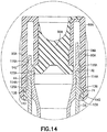
FIG. 14 is a close-up cross-sectional view of the cap shown inFIG. 13 taken alongsegment 14 in accordance with an embodiment of the present invention. -
FIG. 15 is a frontwardly directed perspective view of an alternative embodiment of a specimen collection container assembly in accordance with an embodiment of the present invention. -
FIG. 16 is a cross-sectional side view of the specimen collection container assembly shown inFIG. 15 taken along line 16-16 in accordance with an embodiment of the present invention. -
FIG. 17 is a close-up cross-sectional view of the cap shown inFIG. 16 taken alongsegment 17 in accordance with an embodiment of the present invention. -
FIG. 18 is a frontwardly directed perspective view of an alternative embodiment of a specimen collection container assembly in accordance with an embodiment of the present invention. -
FIG. 19 is a perspective view of the cap of the specimen collection container assembly shown inFIG. 18 in accordance with an embodiment of the present invention. -
FIG. 20 is a cross-sectional view of the cap shown inFIG. 19 taken along line 20-20 in accordance with an embodiment of the present invention. -
FIG. 21 is a cross-sectional side view of the specimen collection container assembly shown inFIG. 18 taken along line 21-21 in accordance with an embodiment of the present invention. -
FIG. 22 is a close-up cross-sectional view of the cap shown inFIG. 21 taken alongsegment 22 in accordance with an embodiment of the present invention. - As shown in
FIG. 1 , a specimencollection container assembly 30, such as a biological fluid collection container, includes aninner tube 32, anouter tube 34, and aspecimen cap 86. Theinner tube 32, as shown inFIGS. 4-5 , is used for the collection and containment of a specimen, such as capillary blood or other bodily fluid, for subsequent testing procedures and diagnostic analysis. Theouter tube 34, as shown inFIGS. 6-7 , acts primarily as a carrier for theinner tube 32, providing additional protection for the contents of theinner tube 32 as well as providing external dimensions that are compatible with standard automated clinical laboratory processes, such as Clinical Laboratory Automation. Thespecimen cap 86, as shown inFIGS. 2-3 , provides a means for a user to access theinner tube 32 to obtain the specimen deposited therein, and also provides a leak proof seal with theinner tube 32 upon replacement of thespecimen cap 86, as will be discussed herein. - Referring specifically to
FIGS. 4-5 , theinner tube 32 includes an opentop end 38, a closedbottom end 40, and asidewall 42 extending therebetween defining aninner tube interior 44 adapted to receive a specimen therein. Referring toFIG. 4 , the opentop end 38 may include at least onefunnel 46 or scoop portion for facilitating and directing a specimen into the interior 44 of theinner tube 32. Thefunnel 46 includes at least one introducingsurface 48 having a curvature for guiding a specimen down thefunnel 46 and into the interior 44 of theinner tube 32. In use, thefunnel 46 may be placed adjacent a specimen and used to "scoop" the specimen into theinner tube 32. In certain instances thefunnel 46 may be placed adjacent a patient's fingertip, and thefunnel 46 may be used to scoop capillary blood into theinner tube 32. - Referring to
FIG. 5 , in other configurations, the opentop end 38 of theinner tube 32 may includedual funnels dual funnels surface 48A of thefirst funnel 46A faces the corresponding curvature of the introducingsurface 48B of thesecond funnel 46B, thereby forming afinger receiving surface 50. In use, a patient's finger tip may be placed in contact with thefinger receiving surface 50 for directing capillary blood into the interior 44 of theinner tube 32. - The
inner tube 32 may also include anannular ring 52 disposed about a portion of thesidewall 42. In certain configurations, theannular ring 52 is disposed adjacent the opentop end 38 and extends outwardly from anexterior surface 54 of thesidewall 42. Theinner tube 32 may further include anannular protrusion 68 extending outwardly from theexterior surface 54 of thesidewall 42. In another embodiment, theannular protrusion 68 may extend inwardly into an interior of theinner tube 32. In certain configurations, theannular protrusion 68 may be positioned below theannular ring 52. - The open
top end 38 of theinner tube 32 may be adapted to provide a sufficiently wide opening to allow standard diagnostic and sampling probes, needles, and/or similar extraction or deposition devices to enter the opentop end 38 and access the interior 44 for the purpose of depositing a specimen therein or withdrawing a specimen therefrom. In one embodiment, theinterior 44 of theinner tube 32 may include at least one angled directingsurface 58 for directing a standard instrument probe or other device toward the closedbottom end 40 of theinner tube 32. In certain configurations it is desirable for both the introducingsurface 48 of thefunnel 46 and the angled directingsurface 58 to be smooth and gradual surfaces to promote the flow of specimen into the interior 44 of theinner tube 32. - In one embodiment, the dimensions of the
inner tube 32 are balanced such that the open top end has an opening having a sufficient width W, as shown inFIG. 4 , to allow a standard instrument probe to pass therethrough, and also to have an inner tube diameter D sufficient to provide the greatest column height of a specimen disposed within theinterior 44 of theinner tube 32. - During a sampling procedure, an increased specimen column height within the
inner tube 32, provides for a greater volume of specimen that may be retrieved or extracted by an analyzer probe (not shown). - At least one
stabilizer 56 may be provided on theexterior surface 54 of thesidewall 42. Thestabilizer 56, as shown inFIGS. 4-5 , may have any suitable shape such that anouter surface 59 contacts at least a portion of theouter tube 34, as shown inFIGS. 6-7 . Referring toFIGS. 6-7 , theouter tube 34 has an opentop end 60, a closedbottom end 62, and asidewall 64 extending therebetween and forming anouter tube interior 66. Thesidewall 64 of theouter tube 34 includes aninner surface 72 and anouter surface 74 and may include at least onerecess 70 extending into a portion of thesidewall 64, such as into theinner surface 72 of a portion of thesidewall 64 adjacent the opentop end 60. Therecess 70 is adapted to receive at least a portion of theannular protrusion 68 of theinner tube 32 therein during assembly. - Referring to
FIG. 7 , theouter surface 74 may also include anannular ring 76 extending outwardly from theouter surface 74 of thesidewall 64 adjacent the opentop end 60. In certain configurations, theannular ring 76 is positioned below therecess 70 along thesidewall 64. - Referring again to
FIGS. 6-7 , theouter tube 34 is dimensioned to receive the inner tube, as shown inFIGS. 4-5 at least partially therein, as shown inFIGS. 8-9 . In one embodiment, theouter tube 34 has sufficient inner dimensions to accommodate theinner tube 32 therein. During assembly, theinner tube 32 may be at least partially positioned within theouter tube 34 such that anupper end 78 of theouter tube 34 abuts theannular ring 52 of theinner tube 32 allowing for a receiving portion of the inner tube having a length L, shown inFIG. 4 , to be received within theouter tube interior 66, as shown inFIG. 8 . Referring specifically toFIG. 4 , the receiving portion of theinner tube 32 has a diameter D1 that is dimensioned for receipt within theouter tube interior 66 and is smaller than the inner diameter D3 of theouter tube 34, as shown inFIG. 6 . Theannular ring 52 of theinner tube 32 is dimensioned to restrain any further portion of theinner tube 32 from passing within theouter tube 34 and has a diameter D2, shown inFIG. 4 , that is greater than the inner diameter D3 of theouter tube 34. As described above, during assembly therecess 70 of theouter tube 34 is adapted to receive at least a portion of theannular protrusion 68 of theinner tube 32 therein, as shown inFIGS. 8-9 . - Although the
inner tube 32 and theouter tube 34 may have any suitable dimensions, the inner tube may have an overall length L2 of about 48 mm, as shown inFIG. 5 , and have an inner tube diameter D of about 7 mm, as shown inFIG. 4 . Theouter tube 34 may have any suitable dimensions that are compatible with standard industry specifications for automated clinical processes, such as having an overall length L3 of about 69 mm, as shown inFIG. 6 , and an outer diameter D4 of about 13 mm. Theouter tube 34 may also be dimensioned to accommodate standard size labels applied to theouter surface 74 and may be dimensioned to improve manipulation by a clinician. This can be particularly advantageous when collecting small volume samples of specimen. A clinician can manipulate theouter tube 34, which is significantly easier to hold, while collecting a small volume specimen within theinner tube 32 disposed within theouter tube 34. When theinner tube 32 and theouter tube 34 are assembled, the overall length L5 may be the industry standard length of 75 mm, as shown inFIG. 8 , or an industry standard length of 100 mm. - In one embodiment, the
inner tube 32 and theouter tube 34 may be in-molded in which both theinner tube 32 and theouter tube 34 are molded in the same press and assembled, as opposed to being separately molded and subsequently assembled. Alternatively, theinner tube 32 and theouter tube 34 may be press-fit within the same forming process. By forming both theinner tube 32 and theouter tube 34 together, the tolerances of the relative engagement between theinner tube 32 and theouter tube 34 may be improved because the relative rate of shrink is the same for both tubes. In certain configurations, theinner tube 32 and theouter tube 34 may be formed of the same material, such as polypropylene and/or polyethylene. In other configurations, theinner tube 32 and theouter tube 34 may be formed of two different polymeric materials. In certain embodiments it is noted that an assembly having aninner tube 32 and anouter tube 34 having thin walls allows for optical clarity of the sample when viewed by an automated vision system, assisting in sample and quality detection. In addition, increased optical clarity may assist a medical practitioner during collection of a specimen. - During assembly and/or formation of the
inner tube 32 and theouter tube 34, air may become trapped between theinner surface 72 of theouter tube 34 and theexterior surface 54 of thesidewall 42 of theinner tube 32. Accordingly, thebottom end 62 of theouter tube 34 may include avent 80, as shown inFIG. 7 , for allowing air trapped between the inner surface of theouter tube 34 and theexterior surface 54 of thesidewall 42 of theinner tube 32 to escape therethrough. In certain configurations, thevent 80 may also assist in the molding process of theinner tube 32 by locking the core pin of the mold during the molding process to prevent relative shifting between theouter tube 34 and the formation of theinner tube 32. - In one embodiment of the present invention, at least one of the
inner tube 32 and theouter tube 34 include at least one fill-line 82, shown inFIGS. 4-5 , for allowing a clinician to determine the volume of specimen within theinner tube 32. In another embodiment, at least one of theinner tube 32 and theouter tube 34 includes a colored orlight blocking additive 84, as shown inFIG. 8 . The additive may allow sufficient light to pass through thesidewall 42 of theinner tube 32 to allow a clinician to visualize the contents of the interior 44 of theinner tube 32, and to also prevent enough light from passing through thesidewall 42 of theinner tube 32 to compromise or otherwise alter the contents of theinner tube 32. This application is particularly useful for specimens collected for light sensitive analytes, such as Bilirubin, as light degrades the specimen quality required for this testing procedure. In one embodiment, the additive may be sprayed, coated, or in-molded with at least one of theinner tube 32 and theouter tube 34. In another embodiment, the additive is intended to block only certain wavelengths of light from passing through thesidewall 42 of theinner tube 32. - Referring to
FIGS. 2-3 , aspecimen collection cap 86 is provided for sealing the opentop end 38 of theinner tube 32 and/or the opentop end 60 of theouter tube 34. In one embodiment, once theinner tube 32 and theouter tube 34 are assembled, the opentop end 60 of theouter tube 34 is sealed by the opentop end 38 of theinner tube 32, specifically by theannular ring 52 of theinner tube 32. Accordingly, in this configuration thespecimen collection cap 86 may only seal the opentop end 38 of theinner tube 32 but effectively seals the opentop end 60 of theouter tube 34 as well. Thespecimen collection cap 86 includes atop surface 88 and anannular shoulder 90 depending therefrom. Thespecimen collection cap 86 may also include an annularinterior wall 92 depending from thetop surface 88, with theannular shoulder 90 circumferentially disposed about the annularinterior wall 92 and spaced therefrom by atube receiving portion 94. - In one embodiment, an elastomeric stopper or
pierceable septum 96 may be disposed at least partially within the annularinterior wall 92 and extending therebetween forming a sealing body within thespecimen collection cap 86. In one embodiment, thepierceable septum 96 is formed from a thermoplastic elastomer (TPE). Thepierceable septum 96 may be pierced by a needle cannula or probe, as is conventionally known, and may be self-sealing. Thepierceable septum 96 may be formed through an offsetflow channel 98, as is described in United States Patent Publication No.2009/0308184 , the entire disclosure of which is hereby incorporated by reference. Thepierceable septum 96 may include aconcave receiving surface 100 adjacent thetop surface 88 for directing an instrument, such as a needle cannula or a probe, to the apex 102 of theconcave receiving surface 100. This allows a clinician to more easily determine proper placement of the needle cannula or probe for puncturing thepierceable septum 96. Anopening 104 within thetop surface 88 of thespecimen collection cap 86 may also be dimensioned to accommodate standard clinical probes and needle cannulae for both hematology and chemistry analysis therethrough. Thepierceable septum 96 also includes aspecimen directing surface 106 for funneling a specimen into an apex 108 of thespecimen collection cap 86 when the specimencollection container assembly 30, shown inFIG. 1 , is inverted for specimen withdrawal, as is described in United States Patent Publication No.2009/0308184 . - Referring again to
FIG. 3 , the annularinterior wall 92 may have aninner surface 110 contacting thepierceable septum 96. A portion of theinner surface 110 of the annularinterior wall 92 may include aseptum restraining portion 112 for preventing the inadvertent advancement of thepierceable septum 96 through thespecimen collection cap 86 when pressure is applied to thepierceable septum 96 by a needle cannula or probe. Theseptum restraining portion 112 extends at least partially into thepierecable septum 96 for creating a physical restraint therebetween. - The
annular shoulder 90 of thespecimen collection cap 86 has aninner surface 114 having afirst protrusion 116 extending from theinner surface 114 into thetube receiving portion 94, and asecond protrusion 118 extending from theinner surface 114 into thetube receiving portion 94. Thefirst protrusion 116 is spaced apart from thesecond protrusion 118, such as laterally offset therefrom along a portion of theinner surface 114 of theannular shoulder 90. Thefirst protrusion 116 and thesecond protrusion 118 may extend annularly into thetube receiving portion 94. - As shown in
FIGS. 8-9 , when thespecimen collection cap 86 and theinner tube 32 andouter tube 34 are combined, theannular shoulder 90 is positioned over theexterior surface 54 of thesidewall 42 of theinner tube 32 and theouter surface 74 of thesidewall 64 of theouter tube 34. Thepierceable septum 96 contacts and forms abarrier seal 122 with a portion of the interior 44 of theinner tube 32, thereby sealing the interior 44 from the external atmosphere. Thefunnel 46, and portions of the opentop end 38 of theinner tube 32 and the portions of the opentop end 60 of theouter tube 34 are received within thetube receiving portion 94. Thefirst protrusion 116 and thesecond protrusion 118 form afirst recess 120 therebetween for accommodating theannular ring 52 of theinner tube 32 therein, thereby forming afirst seal 124 between thespecimen collection cap 86 and theinner tube 32. - Referring again to
FIG. 3 , thespecimen collection cap 86 may also include athird protrusion 126 extending from theinner surface 114 of theannular shoulder 90 into thetube receiving portion 94. Thethird protrusion 126 may extend annularly into thetube receiving portion 94 and may be provided adjacent abottom end 128 of theannular shoulder 90. Referring again toFIG. 9 , when thespecimen collection cap 86,inner tube 32, andouter tube 34 are combined, thethird protrusion 126 may engage a portion of theouter surface 74 of thesidewall 64 of theouter tube 34 forming asecond seal 130. - The
barrier seal 122 formed between thepierceable septum 96 and the interior 44 of theinner tube 32 maintains the interior 44 in a sterile condition prior to receipt of a specimen therein. Thebarrier seal 122 also maintains the condition of the specimen present within theinner tube 32 after recapping or re-sealing of thepierceable septum 96. Thefirst seal 124 and thesecond seal 130 form a tortuous path between the external atmosphere and thebarrier seal 122 further enhancing the overall sealing system of the specimencollection container assembly 30, shown inFIG. 1 . In addition, thefirst seal 124 and thesecond seal 130 maintain thefunnel 46 in a sterile condition prior to use. - Optionally, as shown in
FIGS. 1-2 , theannular shoulder 90 of thespecimen collection cap 86 may include a plurality ofribs 132 extending along a portion of anexterior surface 134 of theannular shoulder 90. Theseribs 132 may be used to help identify the intended contents of theinner tube 32, additives and/or amounts of additives present within theinner tube 32, and/or the intended testing procedure to be performed on the contents of theinner tube 32. - With reference to
FIGS. 10-14 , an alternativespecimen collection cap 86A is shown. Thespecimen collection cap 86A is adapted for use with theinner tube 32 and/or theouter tube 34 as described herein, and is substantially similar to thespecimen collection cap 86, with several alternatives. Specifically, a sealingband 138 is disposed annularly about aninterior surface 114A of anannular shoulder 90A and extends into atube receiving portion 94A. The sealingband 138 forms ahermetic seal 136 with a portion of theouter surface 74 of theouter tube 34. In one embodiment, the sealingband 138 is deformable against anannular ring 76 extending from theouter surface 74 of theouter tube 34, as shown inFIG. 7 , to form thehermetic seal 136. In certain embodiments, theannular shoulder 90A of thespecimen collection cap 86A may include a strengtheningmember 140 adjacent thesealing band 138 for providing additional rigidity to thespecimen collection cap 86A during engagement with theinner tube 32 and/or theouter tube 34. - The presence of the sealing
band 138 at a bottom end 128A of theannular shoulder 90A allows for a reduction in the amount of material present in apierceable septum 96A forming abarrier seal 122A with a portion of the interior 44 of theinner tube 32, thereby sealing the interior 44 from the external atmosphere. In this configuration, aseal 142 is formed by the interaction of thehermetic seal 136 and the interaction of afirst protrusion 116A extending from theinner surface 114A of theannular shoulder 90A into thetube receiving portion 94A and theannular ring 52 of theinner tube 32. Theseal 142 and thehermetic seal 136 form a tortuous path between the external atmosphere and thebarrier seal 122A further enhancing the overall sealing system of the specimencollection container assembly 30, shown inFIG. 1 . - In one embodiment, the engagement of the sealing
band 138 and theannular ring 76 extending from theouter surface 74 of theouter tube 34 produces an audible and/or tactile indication that thespecimen collection cap 86A and theouter tube 34 with theinner tube 32 disposed therein are sealingly engaged. In one configuration, theannular ring 76 may include a resistance protrusion and thesealing band 138 may include a corresponding resistance recess for accommodating the resistance protrusion therein. - As shown in
FIGS. 11-12 , theannular shoulder 90A of thespecimen collection cap 86A may include a plurality ofalternative ribs 132A extending along a portion of anexterior surface 134A of theannular shoulder 90A. Theseribs 132A may be used to help identify the intended contents of theinner tube 32, additives and/or amounts of additives present within theinner tube 32, and/or the intended testing procedure to be performed on the contents of theinner tube 32. - As shown in
FIGS. 15-17 , thespecimen collection cap 86A is also suitable for use withinner tube 32 havingdual funnels FIG. 17 , thedual funnels tube receiving portion 94A, as described herein. - Referring to
FIGS. 18-22 , an alterativespecimen collection cap 86B is shown. Thespecimen collection cap 86B is adapted for use with theinner tube 32 and/or theouter tube 34 as described herein, and is substantially similar to thespecimen collection cap 86, with several alternatives. Specifically, in accordance with an embodiment of the present invention, thespecimen collection cap 86B includes atop surface 88B having anannular shoulder 90B depending therefrom and at least partially surrounding thepierceable septum 96B. In this configuration, thepierceable septum 96B includes abase portion 144 and anouter portion 146 circumferentially disposed about thebase portion 144 and defining atube receiving portion 148 therebetween. - When the
specimen collection cap 86B and theinner tube 32 andouter tube 34 are assembled, thefunnel 46, such asdual funnels tube receiving portion 148. Thetube receiving portion 148 may be dimensioned such that aspacing gap 152 is present on either side of thefunnels inner tube 32 is engaged with thespecimen collection cap 86B. Thespacing gap 152 reduces contact between thefunnels pierceable septum 96B during assembly of thespecimen collection cap 86B and theinner tube 32. This may be particularly advantageous for preventing or minimizing pull-away of thepierceable septum 96B during disengagement of thespecimen collection cap 86B and theinner tube 32. - In a further embodiment, a
bottom end 150 of theouter portion 146 of thepierceable septum 96B may include atapered surface 154 for guiding the opentop end 38, particularly thefunnels tube receiving portion 148 of thepierceable septum 96B. - The
pierceable septum 96B may contact and form abarrier seal 122 with a portion of the interior 44 of theinner tube 32, thereby sealing the interior 44 from the external atmosphere, as described herein. Thepierceable septum 96B may also form aperimeter seal 156 between a portion of theouter portion 146 and theannular ring 52 of theinner tube 32. In certain configurations, anupper tip 160 of thefunnels uppermost region 162 of thetube receiving portion 148 forming atertiary seal 164 therebetween. Thetertiary seal 164 and theperimeter seal 156 form a tortuous path between the external atmosphere and thebarrier seal 122 further enhancing the overall sealing system of a specimencollection container assembly 30B, shown inFIG. 18 . - In a further embodiment, an
inner surface 114B of theannular shoulder 90B may include aseptum restraining portion 112B for preventing the inadvertent advancement of thepierceable septum 96B through thespecimen collection cap 86B when pressure is applied to thepierceable septum 96B by a needle cannula or probe. Theseptum restraining portion 112B extends at least partially into thepierceable septum 96B for creating a physical restraint therebetween. In still a further embodiment, thepierceable septum 96B may include a restrainingportion 170 for bearing against aninner surface 172 of thetop surface 88B for preventing inadvertent disengagement of thespecimen collection cap 86B. - As shown in
FIGS. 18-19 , theannular shoulder 90B of thespecimen collection cap 86B may include a plurality ofalternative ribs 132B extending along a portion of anexterior surface 134B of theannular shoulder 90B. Theseribs 132B may be used to help identify the intended contents of theinner tube 32, additives and/or amounts of additives present within theinner tube 32, and/or the intended testing procedure to be performed on the contents of theinner tube 32. - While specific embodiments of the invention have been described in detail, it will be appreciated by those skilled in the art that various modifications and alternatives to those details could be developed in light of the overall teachings of the disclosure.
-
Aspect 1. A specimen collection container, comprising: - an inner tube having a closed bottom end, a top end, and a sidewall extending therebetween defining an inner tube interior, the sidewall having an inner surface and an outer surface having at least one annular protrusion extending therefrom, the inner tube comprising at least one funnel portion adjacent the top end for directing a specimen into the inner tube interior, and an annular ring disposed about a portion of the outer surface of the sidewall adjacent the top end; and
- an outer tube comprising a bottom end, a top end, and a sidewall extending therebetween, the sidewall having an outer surface and an inner surface defining an annular recess adapted to receive at least a portion of the annular protrusion therein, wherein the inner tube is disposed at least partially within the outer tube and a portion of the top end of the outer tube abuts the annular ring.
- Aspect 2. The specimen collection container of
Aspect 1, wherein the inner tube and the outer tube are co-formed. -
Aspect 3. The specimen collection container ofAspect 1, wherein the open top end of the inner tube comprises a second funnel, such that the second funnel is substantially opposite the funnel. - Aspect 4. The specimen collection container of
Aspect 1, wherein at least one of the sidewall of the inner tube and the sidewall of the outer tube includes at least one fill-line. -
Aspect 5. The specimen collection container ofAspect 1, wherein the bottom end of the outer tube comprises at least one vent for venting air from the space defined between the inner surface of the outer tube and the outer surface of the inner tube. - Aspect 6. The specimen collection container of
Aspect 1, wherein the outer surface of the inner tube comprises at least one stabilizer extending therefrom for contacting a portion of the inner surface of the outer tube. - Aspect 7. The specimen collection container of
Aspect 1, wherein the inner tube completely seals the top end of the outer tube. -
Aspect 8. The specimen collection container ofAspect 1, further comprising a specimen collection cap sealing at least one of the top end of the inner tube and the top end of the outer tube. -
Aspect 9. The specimen collection container ofAspect 8, wherein the specimen collection cap includes a top surface, an annular shoulder depending therefrom, and an annular interior wall depending from the top surface with the annular shoulder circumferentially disposed about the annular interior wall. - Aspect 10. The specimen collection container of
Aspect 9, wherein a tube receiving portion is defined between the annular shoulder and the annular interior wall, and wherein at least a portion of the funnel is received within the tube receiving portion. - Aspect 11. The specimen collection container of Aspect 10, wherein the annular shoulder comprises an inner surface having a first protrusion extending therefrom into the tube receiving portion, and a second protrusion extending therefrom into the tube receiving portion, the first protrusion laterally offset from the second protrusion.
-
Aspect 12. The specimen collection container of Aspect 11, further comprising a protrusion disposed on the outer surface of at least one of the inner tube and the outer tube, the protrusion positioned between the first protrusion and the second protrusion of the annular shoulder when the specimen collection cap seals at least one of the top end of the inner tube and the top end of the outer tube -
Aspect 13. The specimen collection container of Aspect 10, wherein the inner surface of the annular shoulder further comprises a third protrusion disposed about a bottom end of the specimen collection cap extending into the tube receiving portion for contacting a portion of the sidewall of at least one of the inner tube and the outer tube. -
Aspect 14. The specimen collection container ofAspect 9, further comprising an elastomeric stopper at least partially surrounded by the interior annular wall. - Aspect 15. The specimen collection container of
Aspect 14, wherein the elastomeric stopper is self-sealing. -
Aspect 16. The specimen collection container ofAspect 14, wherein the elastomeric stopper comprises a concave receiving surface adjacent the top surface of the specimen collection cap for directing an instrument to an apex of the concave receiving surface. -
Aspect 17. The specimen collection container ofAspect 14, wherein the elastomeric stopper comprises an inverted receiving surface adjacent a bottom end of the specimen collection cap. - Aspect 18. The specimen collection container of
Aspect 9, further comprising a plurality of ribs extending along a portion of an exterior surface of the annular shoulder. - Aspect 19. The specimen collection container of
Aspect 8, wherein the specimen collection cap includes a top surface and an annular shoulder depending therefrom having an inner surface, wherein at least a portion of the inner surface of the annular shoulder and the outer surface of the inner tube interact to form a seal. -
Aspect 20. The specimen collection container of Aspect 19, wherein the seal comprises a tortuous fluid path. -
Aspect 21. The specimen collection container ofAspect 8, wherein the specimen collection cap includes a top surface and an annular shoulder depending therefrom having an inner surface, wherein at least a portion of the inner surface of the annular shoulder and the outer surface of the outer tube interact to form a seal. -
Aspect 22. The specimen collection container ofAspect 21, wherein the seal comprises a tortuous fluid path.
Claims (13)
- A specimen collection container comprising:an inner tube having a closed bottom end, a top end, and a sidewall extending therebetween defining an inner tube interior, said sidewall having an inner surface including at least one angled surface extending toward the closed bottom end, the inner tube comprising at least one funnel portion adjacent the top end, said funnel portion including at least one introducing surface having a curvature configured for directing a specimen down the funnel and into the inner tube interior, said angled surface and said at least one introducing surface together forming a combined angled surface; andan outer tube comprising a bottom end, a top end including an upper end, and a sidewall extending therebetween, wherein the inner tube is disposed at least partially within the outer tube such that the at least one funnel portion sits above the upper end of the outer tube, wherein the sidewall of the inner tube is configured to cooperate with the sidewall of the outer tube to secure the inner tube within the outer tube, wherein the sidewall of the inner tube has an outer surface having at least one annular protrusion extending therefrom and the sidewall of the outer tube has an inner surface defining an annular recess adapted to receive at least a portion of the annular protrusion therein to secure the inner tube within the outer tube.
- The specimen collection container of claim 1, wherein the sidewall of the inner tube includes an annular ring extending outwardly therefrom and the at least one funnel portion is located adjacent to and above the annular ring and wherein a portion of the upper end of the outer tube abuts the annular ring.
- The specimen collection container of claim 1, wherein the top end of the inner tube comprises a second funnel portion, such that the second funnel portion is substantially opposite the at least one funnel portion.
- The specimen collection container of claim 1, wherein at least one of the sidewall of the inner tube and the sidewall of the outer tube includes at least one fill-line for allowing a clinician to determine the volume of specimen within the inner tube.
- The specimen collection container of claim 1, wherein the bottom end of the outer tube comprises at least one vent for venting air from the space defined between the inner tube and the outer tube.
- The specimen collection container of claim 1, wherein the inner tube comprises at least one stabilizer extending therefrom and extending along the sidewall of the inner tube in a longitudinal direction for contacting a portion of an inner surface of the sidewall of the outer tube.
- The specimen collection container of claim 1, wherein the inner tube completely seals the top end of the outer tube.
- The specimen collection container of claim 1, wherein the inner tube and the outer tube are formed from two different polymeric materials.
- The specimen collection container of claim 1, wherein said top end of said inner tube has a receiving portion diameter D1 and an annular ring having an outer diameter D2 that is greater than D1, said at least one funnel portion being located adjacent to and extending above the annular ring, and
wherein the outer tube has an outer tube interior having an inner diameter D3 which is greater than D1 and less than D2. - The specimen collection container of claim 9, wherein the inner tube has an overall length L2, the outer tube has an overall length L3 which is greater than L2, and wherein assembly of the inner tube within the outer tube results in the specimen collection container having an overall length L5 which is greater than L3.
- The specimen collection container of claim 1, wherein an overall length of the container is between 75 mm and 100 mm.
- The specimen collection container of claim 1, further comprising a specimen collection cap sealing at least one of the top end of the inner tube and the top end of the outer tube.
- The specimen collection container of claim 12, wherein the specimen collection cap includes a top surface, an annular shoulder depending therefrom, and an annular interior wall depending from the top surface with the annular shoulder circumferentially disposed about the annular interior wall
Priority Applications (1)
| Application Number | Priority Date | Filing Date | Title |
|---|---|---|---|
| EP21166535.1A EP3871775A1 (en) | 2010-12-03 | 2011-11-15 | Specimen collection container assembly |
Applications Claiming Priority (4)
| Application Number | Priority Date | Filing Date | Title |
|---|---|---|---|
| US41958710P | 2010-12-03 | 2010-12-03 | |
| US13/295,235 US8460620B2 (en) | 2010-12-03 | 2011-11-14 | Specimen collection container assembly |
| EP11790822.8A EP2646158B1 (en) | 2010-12-03 | 2011-11-15 | Specimen collection container assembly |
| PCT/US2011/060781 WO2012074738A1 (en) | 2010-12-03 | 2011-11-15 | Specimen collection container assembly |
Related Parent Applications (1)
| Application Number | Title | Priority Date | Filing Date |
|---|---|---|---|
| EP11790822.8A Division EP2646158B1 (en) | 2010-12-03 | 2011-11-15 | Specimen collection container assembly |
Related Child Applications (1)
| Application Number | Title | Priority Date | Filing Date |
|---|---|---|---|
| EP21166535.1A Division EP3871775A1 (en) | 2010-12-03 | 2011-11-15 | Specimen collection container assembly |
Publications (2)
| Publication Number | Publication Date |
|---|---|
| EP3320974A1 true EP3320974A1 (en) | 2018-05-16 |
| EP3320974B1 EP3320974B1 (en) | 2021-04-07 |
Family
ID=46162419
Family Applications (3)
| Application Number | Title | Priority Date | Filing Date |
|---|---|---|---|
| EP21166535.1A Pending EP3871775A1 (en) | 2010-12-03 | 2011-11-15 | Specimen collection container assembly |
| EP17207073.2A Active EP3320974B1 (en) | 2010-12-03 | 2011-11-15 | Specimen collection container assembly |
| EP11790822.8A Active EP2646158B1 (en) | 2010-12-03 | 2011-11-15 | Specimen collection container assembly |
Family Applications Before (1)
| Application Number | Title | Priority Date | Filing Date |
|---|---|---|---|
| EP21166535.1A Pending EP3871775A1 (en) | 2010-12-03 | 2011-11-15 | Specimen collection container assembly |
Family Applications After (1)
| Application Number | Title | Priority Date | Filing Date |
|---|---|---|---|
| EP11790822.8A Active EP2646158B1 (en) | 2010-12-03 | 2011-11-15 | Specimen collection container assembly |
Country Status (10)
| Country | Link |
|---|---|
| US (3) | US8460620B2 (en) |
| EP (3) | EP3871775A1 (en) |
| JP (3) | JP5670583B2 (en) |
| CN (1) | CN103237602B (en) |
| AU (1) | AU2011337010B2 (en) |
| BR (1) | BR112013013251B1 (en) |
| CA (1) | CA2818606C (en) |
| ES (2) | ES2866982T3 (en) |
| MX (1) | MX356294B (en) |
| WO (1) | WO2012074738A1 (en) |
Families Citing this family (28)
| Publication number | Priority date | Publication date | Assignee | Title |
|---|---|---|---|---|
| US8460620B2 (en) | 2010-12-03 | 2013-06-11 | Becton, Dickinson And Company | Specimen collection container assembly |
| US9442046B2 (en) | 2011-06-19 | 2016-09-13 | Abogen, Inc. | Device for sample collection |
| US10500589B2 (en) * | 2013-03-01 | 2019-12-10 | Siemens Healthcare Diagnostics Inc. | Self aligning wedge container with anti-evaporation tube |
| AU2013202805B2 (en) | 2013-03-14 | 2015-07-16 | Gen-Probe Incorporated | System and method for extending the capabilities of a diagnostic analyzer |
| AU2013202778A1 (en) | 2013-03-14 | 2014-10-02 | Gen-Probe Incorporated | Systems, methods, and apparatuses for performing automated reagent-based assays |
| CN103284731B (en) * | 2013-06-04 | 2015-01-07 | 威海鸿宇医疗器械有限公司 | Light-resistant blood collection tube |
| USD754361S1 (en) * | 2013-09-06 | 2016-04-19 | Theranos, Inc. | Sample container |
| AT514833B1 (en) * | 2013-10-11 | 2015-07-15 | Greiner Bio One Gmbh | Acceptance module, in particular for blood samples |
| WO2015100169A1 (en) | 2013-12-27 | 2015-07-02 | William Beaumount Hospital | Container closure, container assembly and method for utilizing the same |
| CN106232233B (en) * | 2014-04-25 | 2018-07-10 | 西门子医疗保健诊断公司 | Sample collection unit |
| US10093918B2 (en) | 2014-06-04 | 2018-10-09 | Lucigen Corporation | Sample collection and analysis devices |
| EP3288459B1 (en) * | 2015-04-29 | 2023-09-20 | Revvity Health Sciences, Inc. | Specimen collection and delivery apparatus |
| CN106466645A (en) * | 2015-08-21 | 2017-03-01 | 无锡市凯顺医疗器械制造有限公司 | A kind of test tube |
| USD843008S1 (en) | 2016-01-15 | 2019-03-12 | Biotix, Inc. | Fluid handling tube with cap |
| WO2017123504A1 (en) * | 2016-01-15 | 2017-07-20 | Biotix, Inc. | Cap and fluid handling tube components and assemblies |
| US20190329248A1 (en) * | 2016-02-08 | 2019-10-31 | Nolato Treff Ag Degersheim | Vial, method for transporting vials, and use of a vial |
| USD803395S1 (en) * | 2016-05-10 | 2017-11-21 | Peter Equere | Male urinary incontinence protection sheath |
| US9999888B2 (en) * | 2016-05-19 | 2018-06-19 | Integrated Lab Solutions, Inc. | Specimen container for urine and other liquids |
| EP3463549B1 (en) | 2016-06-03 | 2023-08-16 | Advanced Instruments, LLC | Plug for osmometry sample cup |
| USD865212S1 (en) * | 2016-08-15 | 2019-10-29 | Kobe Bio Robotix Co., Ltd | Sample storage |
| KR102602638B1 (en) * | 2017-05-02 | 2023-11-16 | 그라이너 바이오-원 게엠베하 | Small body fluid collection assembly |
| KR20200009022A (en) * | 2017-05-08 | 2020-01-29 | 산타마리아 클라우디아 | Devices for protecting the inner container |
| WO2019086251A1 (en) * | 2017-11-06 | 2019-05-09 | Calbact Ag | Calorimeter and sample container for a calorimeter |
| CN110398595A (en) * | 2018-04-24 | 2019-11-01 | 深圳市帝迈生物技术有限公司 | A kind of blood sample automatic mixing device and blood cell analysis equipment |
| WO2019206097A1 (en) * | 2018-04-24 | 2019-10-31 | 深圳市帝迈生物技术有限公司 | Blood cell analysis and measurement method and device featuring fully-automatic sample introduction, and method for performing blending operation on test tube containing peripheral blood |
| CN109738656B (en) * | 2019-01-29 | 2022-02-08 | 河北艾欧路生物科技有限责任公司 | Cerebrospinal fluid urine total protein determination kit and reagent preparation method |
| CN111772646B (en) * | 2020-08-11 | 2022-01-28 | 无锡市第五人民医院 | Low sample volume sampler |
| KR20240026201A (en) * | 2021-06-29 | 2024-02-27 | 백톤 디킨슨 앤드 컴퍼니 | Sample container for capillary blood collection |
Citations (9)
| Publication number | Priority date | Publication date | Assignee | Title |
|---|---|---|---|---|
| US3807955A (en) * | 1971-04-15 | 1974-04-30 | Becton Dickinson Co | Serum/plasma isolator cup |
| GB2183159A (en) * | 1985-11-19 | 1987-06-03 | Sarstedt Kunststoff | Blood collecting vessel |
| US5038794A (en) * | 1987-11-16 | 1991-08-13 | Valkenburg Nanci L Van | Capillary blood collector and method |
| EP0877652A1 (en) * | 1996-11-19 | 1998-11-18 | Sarstedt AG & Co. | Sample vessel for taking blood samples |
| EP0901821A2 (en) * | 1997-09-12 | 1999-03-17 | Becton, Dickinson and Company | Collection container assembly |
| US6221307B1 (en) * | 1999-11-10 | 2001-04-24 | Becton Dickinson And Company | Collection container assembly |
| JP2005221485A (en) * | 2004-02-09 | 2005-08-18 | Sekisui Chem Co Ltd | Sample housing device |
| US20090308184A1 (en) | 2008-03-05 | 2009-12-17 | Becton, Dickinson And Company | Co-Molded Pierceable Stopper and Method for Making the Same |
| WO2010036387A2 (en) * | 2008-03-05 | 2010-04-01 | Becton, Dickinson And Company | Capillary action collection device and container assembly |
Family Cites Families (154)
| Publication number | Priority date | Publication date | Assignee | Title |
|---|---|---|---|---|
| US2393578A (en) | 1942-01-09 | 1946-01-22 | Sterling Drug Inc | Closure |
| US2594621A (en) | 1950-08-03 | 1952-04-29 | George W Derrick | Blood obtaining instrument |
| US2698272A (en) | 1950-09-29 | 1954-12-28 | Gillon Company Inc | Method of forming needle-penetrable stoppers for containers |
| US2998726A (en) | 1959-03-13 | 1961-09-05 | Dwain R Madden | Tank sampler |
| DE1187954B (en) | 1962-02-18 | 1965-02-25 | Paul Buschle | Cartridge fountain pen |
| US3136440A (en) * | 1963-06-25 | 1964-06-09 | Becton Dickinson Co | Self sealing pierceable stopper for sealed containers |
| US3297184A (en) | 1963-11-05 | 1967-01-10 | B D Lab Inc | Cap for culture tubes |
| FR1520693A (en) | 1967-03-01 | 1968-04-12 | Oreal | New closure device for vials or similar containers |
| DE1566542A1 (en) | 1967-11-29 | 1971-02-18 | Wimmer Pharma Gummi Gmbh | Pierceable closure for medicine bottles |
| US3630191A (en) | 1969-02-27 | 1971-12-28 | Gilford Instr Labor Inc | Apparatus and method for filling capillary tubing with fluids |
| BE759374A (en) | 1970-06-08 | 1971-04-30 | Ims Ltd | MEDICINE PACKAGING |
| JPS549119B1 (en) | 1970-09-16 | 1979-04-21 | ||
| US4024857A (en) | 1974-12-23 | 1977-05-24 | Becton, Dickinson And Company | Micro blood collection device |
| JPS51122982A (en) * | 1974-12-23 | 1976-10-27 | Becton Dickinson Co | Small blood sampling unit |
| GB1562900A (en) * | 1975-09-24 | 1980-03-19 | Aes Scient Ltd | Preparation of blood plasma and serum samples |
| US4111326A (en) | 1976-03-04 | 1978-09-05 | Becton, Dickinson And Company | Closure for air evacuated container |
| US4156570A (en) | 1977-04-18 | 1979-05-29 | Robert A. Levine | Apparatus and method for measuring white blood cell and platelet concentrations in blood |
| US4163500A (en) | 1978-01-23 | 1979-08-07 | Siemens Aktiengesellschaft | Bottle seal |
| US4201209A (en) | 1978-05-24 | 1980-05-06 | Leveen Harry H | Molded hypodermic plunger with integral shaft and elastomeric head |
| US4215700A (en) * | 1978-08-25 | 1980-08-05 | Sherwood Medical Industries Inc. | Blood collection device |
| US4227620A (en) | 1979-02-28 | 1980-10-14 | Becton, Dickinson And Company | Specimen collecting tube |
| US4308232A (en) | 1979-07-09 | 1981-12-29 | Sherwood Medical Industries Inc. | Anticoagulant stopper coating |
| US4381275A (en) | 1981-01-30 | 1983-04-26 | Trade Finance International | Stabilized core injection molding of plastic |
| US4411163A (en) | 1981-07-27 | 1983-10-25 | American Hospital Supply Corporation | Ventable sample collection device |
| US4397318A (en) * | 1981-08-10 | 1983-08-09 | Becton Dickinson And Company | Blood collector for microcollection container |
| JPS5886173A (en) | 1981-11-16 | 1983-05-23 | 東洋製罐株式会社 | Gasket of container for blood transfusion and preparation thereof |
| US4803031A (en) | 1982-06-03 | 1989-02-07 | Anchor Hocking Corporation | Method and apparatus for molding a closure cap |
| US4508676A (en) | 1982-07-29 | 1985-04-02 | Sorensen Jens Ole | Core stabilization by sequential injections |
| US4635807A (en) | 1983-03-17 | 1987-01-13 | Schering Corporation | Stopper for sterile fluid containers |
| US4724028A (en) | 1983-04-15 | 1988-02-09 | Baxter Travenol Laboratories | Method of manufacturing disc-shaped rubber articles, such as injection sites |
| SE437348B (en) | 1983-07-29 | 1985-02-25 | Pharmacia Ab | CLOSING DEVICE FOR THE FLUID DUMP CONNECTION OF AN OPENING OF A FLUIDUM CONTAINER OR FLUIDUM PIPE |
| US4558947A (en) | 1983-11-07 | 1985-12-17 | Wardlaw Stephen C | Method and apparatus for measuring blood constituent counts |
| US4576185A (en) * | 1983-12-05 | 1986-03-18 | Terumo Medical Corporation | Collection device for capillary blood |
| USD285115S (en) | 1983-12-05 | 1986-08-12 | Terumo Medical Corporation | Collector for capillary blood |
| JPS60124902U (en) * | 1984-01-31 | 1985-08-23 | テルモ株式会社 | Micro blood sampling device |
| US4620549A (en) * | 1985-01-25 | 1986-11-04 | Becton, Dickinson And Company | Blood collection assembly |
| JPS61247459A (en) | 1985-04-25 | 1986-11-04 | テルモ株式会社 | Plug body for medical container |
| DE3674949D1 (en) | 1985-05-28 | 1990-11-22 | Daikyo Gomu Seiko Kk | RESIN LAMINATED PLASTIC PLUG AND THEIR PRODUCTION. |
| US4690153A (en) | 1985-11-29 | 1987-09-01 | Becton, Dickinson And Company | Flow inducing means for small volume containers |
| JPH0452685Y2 (en) * | 1986-06-24 | 1992-12-10 | ||
| US5019243A (en) | 1987-04-03 | 1991-05-28 | Mcewen James A | Apparatus for collecting blood |
| US4869384A (en) | 1988-01-12 | 1989-09-26 | International Medication Systems Limited | Package for toxic and dangerous drugs |
| US4893636A (en) | 1988-03-09 | 1990-01-16 | Sherwood Medical Company | Medical container stopper |
| US5275299A (en) | 1988-04-15 | 1994-01-04 | C. A. Greiner & Sohne Gesellschaft Mbh | Closure device for an in particular evacuable cylindrical housing |
| DE3818238A1 (en) | 1988-05-28 | 1989-11-30 | Eppendorf Geraetebau Netheler | METHOD FOR REMOVING LIQUID FROM LARGE-VOLUME, DEEP VESSELS AND DEVICE FOR IMPLEMENTING THE METHOD BY SUCTION VESSELS WITH SHORT SUCTION PIECES AS SUCTION AID |
| USD321456S (en) | 1988-11-21 | 1991-11-12 | Dart Industries, Inc. | Cover for a food storage container or the like |
| US4967919A (en) | 1988-11-23 | 1990-11-06 | Sherwood Medical Company | Blood collection tube safety cap |
| US5103836A (en) * | 1990-02-28 | 1992-04-14 | Epitope, Inc. | Oral collection device and kit for immunoassay |
| JPH0620764B2 (en) | 1989-10-23 | 1994-03-23 | 株式会社ニッショー | Method for manufacturing vial rubber stopper |
| US5277874A (en) * | 1990-02-12 | 1994-01-11 | Vasta Gloria J | Mold apparatus for thermally processing a rimmed, sealed, food-filled, plastic container |
| USD325170S (en) | 1990-04-11 | 1992-04-07 | Frantz Dale A | Container lid with spout |
| US5060812A (en) | 1990-09-06 | 1991-10-29 | International Medication Systems, Limited | Medication container stopper which can be punctured by nozzle of a hypodermic syringe |
| USD330660S (en) | 1990-12-06 | 1992-11-03 | Dart Industries, Inc. | Casserole dish cover |
| US5268148A (en) * | 1990-12-18 | 1993-12-07 | Saliva Diagnostic Systems, Inc. | Saliva sampling device and sample adequacy system |
| JPH0774772B2 (en) | 1990-12-31 | 1995-08-09 | エイ. レビン ロバート | Blood sampling assembly, target cell collection method and target component collection method |
| USD334710S (en) | 1991-03-28 | 1993-04-13 | Dart Industries Inc. | Container cover |
| JPH04347141A (en) | 1991-05-23 | 1992-12-02 | Nissho Corp | Sampler for trace blood |
| CA2067695C (en) | 1991-06-06 | 1997-07-08 | James A. Burns | Blood microcollection tube assembly |
| US5279606A (en) | 1991-08-28 | 1994-01-18 | Habley Medical Technology Corporation | Non-reactive composite sealing barrier |
| US5215102A (en) | 1991-10-25 | 1993-06-01 | La Mina Ltd. | Capillary blood antigen testing apparatus |
| US5286453A (en) | 1992-04-02 | 1994-02-15 | Pope Carolyn M | Device for dispensing a biological fluid from a sealed vacuum tube |
| US5232109A (en) | 1992-06-02 | 1993-08-03 | Sterling Winthrop Inc. | Double-seal stopper for parenteral bottle |
| US5379907A (en) | 1993-03-03 | 1995-01-10 | Sterling Winthrop Inc. | Stopper for medication container |
| AU5756094A (en) | 1993-03-31 | 1994-10-06 | Becton Dickinson & Company | Stopper for small diameter blood collection tube |
| CA2094317C (en) | 1993-04-19 | 2003-01-07 | Victor Daykin | Biological specimen collection system |
| US5494170A (en) | 1993-05-06 | 1996-02-27 | Becton Dickinson And Company | Combination stopper-shield closure |
| US5632396A (en) | 1993-05-06 | 1997-05-27 | Becton, Dickinson And Company | Combination stopper-shield closure |
| US5384096A (en) | 1993-05-12 | 1995-01-24 | Becton, Dickinson And Company | Microcollection tube assembly |
| US6939514B1 (en) | 1993-05-14 | 2005-09-06 | Helena Laboratories Corporation | Method and apparatus for dispensing and distributing biological sample |
| USD357985S (en) | 1993-05-27 | 1995-05-02 | Becton Dickinson And Company | Microcollection tube |
| USD356643S (en) | 1993-05-27 | 1995-03-21 | Becton Dickinson And Company | Microcollection tube |
| US5484566A (en) | 1994-03-07 | 1996-01-16 | Wheaton Inc. | Method of manufacture of a partially laminated rubber closure |
| US5527513A (en) | 1994-04-08 | 1996-06-18 | Becton Dickinson And Company | Collection assembly |
| EP0688652B1 (en) | 1994-06-06 | 2000-06-14 | Husky Injection Molding Systems Ltd. | Opposed gating injection method |
| JPH0843959A (en) | 1994-07-29 | 1996-02-16 | Fuji Photo Film Co Ltd | Irradiation light source device for photograph printing device |
| US5458113A (en) | 1994-08-12 | 1995-10-17 | Becton Dickinson And Company | Collection assembly |
| US5647939A (en) | 1994-12-05 | 1997-07-15 | Integrated Liner Technologies, Inc. | Method of bonding a cured elastomer to plastic and metal surfaces |
| JP3634438B2 (en) * | 1995-04-21 | 2005-03-30 | 積水化学工業株式会社 | Vacuum collection tube |
| US5634474A (en) | 1995-04-28 | 1997-06-03 | Becton, Dickinson And Company | Blood collection assembly including clot-accelerating glass insert |
| US5711875A (en) | 1995-11-30 | 1998-01-27 | Becton Dickinson And Company | Cell strainer cap |
| US5716683A (en) | 1996-01-30 | 1998-02-10 | Becton, Dickinson And Company | Blood collection tube assembly |
| US5714125A (en) | 1996-03-07 | 1998-02-03 | Medical Safety Products, Inc. | Device for collecting a blood sample from a plastic segment tube |
| US6727101B1 (en) | 1996-03-07 | 2004-04-27 | Baxter International Inc. | Device for removing a blood sample from a plastic segment tube |
| US5785925A (en) | 1996-08-29 | 1998-07-28 | Saigene Corporation | Centrifuge tube phase separation plug |
| US5902276A (en) | 1996-11-26 | 1999-05-11 | Liebel-Flarsheim Company | Two-shot molded plunger |
| EP0856390B1 (en) | 1997-01-22 | 2004-06-23 | Chisso Corporation | Method for producing a composite molded article of thermoplastic resins |
| US6720044B2 (en) | 1997-02-20 | 2004-04-13 | Pharmacia Ab | Polyolefinic closures comprising penetrable plugs and annular channels |
| US5954104A (en) | 1997-02-28 | 1999-09-21 | Abbott Laboratories | Container cap assembly having an enclosed penetrator |
| US5888184A (en) | 1997-03-10 | 1999-03-30 | Robert A. Levine | Method for rapid measurement of cell layers |
| US5889584A (en) | 1997-03-10 | 1999-03-30 | Robert A. Levine | Assembly for rapid measurement of cell layers |
| USD397295S (en) | 1997-03-17 | 1998-08-25 | Paige Shelton-Ferrell | Dosage indicator |
| US5942191A (en) * | 1997-07-14 | 1999-08-24 | Becton, Dickinson And Company | Body fluid collection vessel having reduced capacity |
| US20020156439A1 (en) | 1997-09-12 | 2002-10-24 | Michael J. Iskra | Collection container assembly |
| JP3872893B2 (en) * | 1997-12-19 | 2007-01-24 | 積水化学工業株式会社 | Vacuum specimen collection tube |
| US6019751A (en) | 1998-01-20 | 2000-02-01 | Bracco Research Usa | Universal connector and a medical container |
| US6165402A (en) | 1998-01-30 | 2000-12-26 | Abbott Laboratories | Method for making a stopper |
| US6080366A (en) | 1998-03-02 | 2000-06-27 | Becton, Dickinson And Company | Disposable blood tube holder |
| US6752965B2 (en) | 1998-03-06 | 2004-06-22 | Abner Levy | Self resealing elastomeric closure |
| US6030582A (en) | 1998-03-06 | 2000-02-29 | Levy; Abner | Self-resealing, puncturable container cap |
| US6221655B1 (en) | 1998-08-01 | 2001-04-24 | Cytosignal | Spin filter assembly for isolation and analysis |
| US6562300B2 (en) | 1998-08-28 | 2003-05-13 | Becton, Dickinson And Company | Collection assembly |
| JP3142521B2 (en) | 1998-11-04 | 2001-03-07 | 大成プラス株式会社 | Needlestick stopcock and its manufacturing method |
| US6077235A (en) | 1999-02-23 | 2000-06-20 | Becton, Dickinson And Company | Blood collection assembly and method therefor |
| US6716396B1 (en) | 1999-05-14 | 2004-04-06 | Gen-Probe Incorporated | Penetrable cap |
| US20010020607A1 (en) | 1999-06-25 | 2001-09-13 | Renzo Chiarin | Assembly of a protected stopper and a test tube, said stopper being used for blood sample collecting or biological liquids handling test tubes |
| US6426049B1 (en) | 1999-07-09 | 2002-07-30 | Becton, Dickinson And Company | Collection assembly |
| USD445908S1 (en) | 1999-08-06 | 2001-07-31 | Becton, Dickinson And Company | Stackable tube assembly |
| USD425625S (en) | 1999-08-06 | 2000-05-23 | Becton, Dickinson And Company | Specimen sampling tube |
| DE60015254T2 (en) | 1999-08-18 | 2006-02-02 | Becton, Dickinson And Co. | Closure consisting of a stopper and a protective cap |
| US6358476B1 (en) | 1999-09-23 | 2002-03-19 | Sharon A. Innamorato | Microcollection tube assembly |
| DE19962664C2 (en) | 1999-12-23 | 2003-01-30 | Helvoet Pharma | Closure device for a vacuum sample collection container |
| US20030133844A1 (en) | 2000-02-25 | 2003-07-17 | Conway Hugh T. | Microcollection tube assembly |
| US20030039717A1 (en) | 2000-05-01 | 2003-02-27 | Hwang C. Robin | Injection molding of thermoplastic parts |
| US6695817B1 (en) | 2000-07-11 | 2004-02-24 | Icu Medical, Inc. | Medical valve with positive flow characteristics |
| US6354452B1 (en) * | 2000-07-25 | 2002-03-12 | Becton, Dickinson And Company | Collection container assembly |
| US20020020416A1 (en) | 2000-08-11 | 2002-02-21 | David Namey | Two-shot injection molded nasal/oral mask |
| US6551267B1 (en) | 2000-10-18 | 2003-04-22 | Becton, Dickinson And Company | Medical article having blood-contacting surface |
| CN100386441C (en) | 2000-11-08 | 2008-05-07 | 贝克顿迪肯森公司 | Method and device for collecting and stabilizing biological sample |
| USD489005S1 (en) | 2001-02-28 | 2004-04-27 | Tri State Distribution, Inc. | Bottle cap |
| US6893612B2 (en) | 2001-03-09 | 2005-05-17 | Gen-Probe Incorporated | Penetrable cap |
| DE10127823C1 (en) | 2001-06-07 | 2002-08-22 | West Pharm Serv Drug Res Ltd | Closure for a medication bottle and process for its manufacture |
| US20030028154A1 (en) | 2001-07-31 | 2003-02-06 | Milton Ross | Polymer hypodermic needle and process for producing same design and process for making all-plastic molded-in-one piece hypodermic needle |
| US6686204B2 (en) | 2001-08-27 | 2004-02-03 | Becton, Dickinson & Company | Collection device |
| DE10144892B4 (en) | 2001-09-12 | 2005-09-08 | Disetronic Licensing Ag | Multilayer plastic body |
| US7022289B1 (en) | 2001-10-10 | 2006-04-04 | The United States Of America As Represented By The Secretary Of The Army | Chemical and biological sampling device and kit and method of use thereof |
| EP1346716A4 (en) | 2001-11-09 | 2010-10-20 | Taisei Plas Co Ltd | Leak stop plug against needle piercing and method of manufacturing the leak stop plug |
| USD470051S1 (en) | 2002-01-03 | 2003-02-11 | Owens-Illinois Closure Inc. | Container closure |
| US7028858B2 (en) | 2002-02-19 | 2006-04-18 | Stull Technologies, | Quick-twist pop-off closure |
| CN100389880C (en) | 2002-05-07 | 2008-05-28 | 贝克顿·迪金森公司 | Collection assembly |
| WO2003097237A2 (en) | 2002-05-13 | 2003-11-27 | Becton, Dickinson, And Company | Protease inhibitor sample collection system |
| US6878346B2 (en) | 2002-05-17 | 2005-04-12 | Bayer Corporation | Serum transfer cup |
| ITVI20020131A1 (en) | 2002-06-17 | 2003-12-17 | Vacutest Kima Srl | CAP WITH PROTECTION FOR TEST TUBES |
| AU2003245718A1 (en) | 2002-06-25 | 2004-01-06 | Stull Technologies | Tamper-evident quick twist closure |
| USD481801S1 (en) | 2002-09-20 | 2003-11-04 | Becton, Dickinson And Company | Cap assembly for a roller bottle |
| USD479997S1 (en) | 2002-09-25 | 2003-09-30 | Societe Des Produits Nestle S.A. | Jar cover |
| BE1015362A6 (en) | 2002-10-14 | 2005-02-01 | Boutech Nv | Manufacture of plungers for medical syringes comprises forming plunger or its part through manufacturing a piston body and plunger body or its part using injection molding, and injecting plunger body or its part against piston body |
| USD490707S1 (en) | 2002-10-15 | 2004-06-01 | Marc J. Mataya | Prescription bottle cap |
| PT1421906E (en) * | 2002-11-20 | 2006-05-31 | Sarstedt Ag & Co | URINE COLLECTION CONTAINER AND ACCESSORIES |
| JP4534506B2 (en) * | 2003-02-03 | 2010-09-01 | ベクトン・ディキンソン・アンド・カンパニー | Container assembly and method of making the assembly |
| USD481948S1 (en) | 2003-03-10 | 2003-11-11 | Owens-Illinois Closure Inc. | Squeeze-and-turn child resistant closure |
| USD481946S1 (en) | 2003-03-31 | 2003-11-11 | Brian Gittler | Medicament dosage indicator |
| GB0315953D0 (en) | 2003-07-08 | 2003-08-13 | Glaxosmithkline Biolog Sa | Process |
| CN100508887C (en) | 2003-07-18 | 2009-07-08 | 积水化学工业株式会社 | Sealed vessel and vacuum specimen collection vessel |
| US20050065454A1 (en) * | 2003-09-22 | 2005-03-24 | Becton, Dickinson And Company | Non-evacuated blood collection tube |
| US20050090766A1 (en) | 2003-10-24 | 2005-04-28 | Renzo Montanari | Tube for blood collecting with a vacuum method |
| JP4796959B2 (en) | 2004-05-27 | 2011-10-19 | 栄研化学株式会社 | Biological sample collection tool and biological sample collection method |
| US20060036231A1 (en) | 2004-05-27 | 2006-02-16 | Conard William A | Injection port and method of making the same |
| DE102004044288A1 (en) | 2004-09-10 | 2006-04-06 | Haindl, Hans, Dr.med. | Device for connecting a tubular part, in particular a cannula, to the inside of a bottle or the like |
| CA2517940A1 (en) | 2004-09-24 | 2006-03-24 | Ems-Chemie Ag | Injection molding method for manufacturing plastic parts |
| USD563785S1 (en) | 2006-04-13 | 2008-03-11 | The Quaker Oats Company | Container cover |
| EP2110174B1 (en) * | 2006-09-08 | 2014-04-02 | Becton, Dickinson and Company | Sample container with physical fill-line indicator |
| US7909197B2 (en) | 2007-05-07 | 2011-03-22 | Whirlpool Corporation | High volume docking seal for bulk liquid dispensing cartridge |
| USD607340S1 (en) | 2008-04-18 | 2010-01-05 | Henkel Ag & Co. Kgaa | Jar |
| US8460620B2 (en) * | 2010-12-03 | 2013-06-11 | Becton, Dickinson And Company | Specimen collection container assembly |
-
2011
- 2011-11-14 US US13/295,235 patent/US8460620B2/en active Active
- 2011-11-15 BR BR112013013251-5A patent/BR112013013251B1/en active IP Right Grant
- 2011-11-15 ES ES17207073T patent/ES2866982T3/en active Active
- 2011-11-15 CA CA2818606A patent/CA2818606C/en active Active
- 2011-11-15 MX MX2013005491A patent/MX356294B/en active IP Right Grant
- 2011-11-15 EP EP21166535.1A patent/EP3871775A1/en active Pending
- 2011-11-15 EP EP17207073.2A patent/EP3320974B1/en active Active
- 2011-11-15 AU AU2011337010A patent/AU2011337010B2/en active Active
- 2011-11-15 EP EP11790822.8A patent/EP2646158B1/en active Active
- 2011-11-15 JP JP2013542025A patent/JP5670583B2/en active Active
- 2011-11-15 CN CN201180058102.3A patent/CN103237602B/en active Active
- 2011-11-15 ES ES11790822.8T patent/ES2663624T3/en active Active
- 2011-11-15 WO PCT/US2011/060781 patent/WO2012074738A1/en active Application Filing
-
2013
- 2013-05-06 US US13/887,680 patent/US9399218B2/en active Active
-
2014
- 2014-12-17 JP JP2014255510A patent/JP2015083985A/en active Pending
-
2016
- 2016-06-15 US US15/183,196 patent/US9962704B2/en active Active
- 2016-11-25 JP JP2016229099A patent/JP6271685B2/en active Active
Patent Citations (9)
| Publication number | Priority date | Publication date | Assignee | Title |
|---|---|---|---|---|
| US3807955A (en) * | 1971-04-15 | 1974-04-30 | Becton Dickinson Co | Serum/plasma isolator cup |
| GB2183159A (en) * | 1985-11-19 | 1987-06-03 | Sarstedt Kunststoff | Blood collecting vessel |
| US5038794A (en) * | 1987-11-16 | 1991-08-13 | Valkenburg Nanci L Van | Capillary blood collector and method |
| EP0877652A1 (en) * | 1996-11-19 | 1998-11-18 | Sarstedt AG & Co. | Sample vessel for taking blood samples |
| EP0901821A2 (en) * | 1997-09-12 | 1999-03-17 | Becton, Dickinson and Company | Collection container assembly |
| US6221307B1 (en) * | 1999-11-10 | 2001-04-24 | Becton Dickinson And Company | Collection container assembly |
| JP2005221485A (en) * | 2004-02-09 | 2005-08-18 | Sekisui Chem Co Ltd | Sample housing device |
| US20090308184A1 (en) | 2008-03-05 | 2009-12-17 | Becton, Dickinson And Company | Co-Molded Pierceable Stopper and Method for Making the Same |
| WO2010036387A2 (en) * | 2008-03-05 | 2010-04-01 | Becton, Dickinson And Company | Capillary action collection device and container assembly |
Also Published As
| Publication number | Publication date |
|---|---|
| BR112013013251B1 (en) | 2020-11-24 |
| EP2646158B1 (en) | 2018-01-03 |
| ES2866982T3 (en) | 2021-10-20 |
| CA2818606C (en) | 2015-06-09 |
| BR112013013251A2 (en) | 2016-09-13 |
| US8460620B2 (en) | 2013-06-11 |
| ES2663624T3 (en) | 2018-04-16 |
| US20130251605A1 (en) | 2013-09-26 |
| EP3320974B1 (en) | 2021-04-07 |
| JP2017067787A (en) | 2017-04-06 |
| JP2015083985A (en) | 2015-04-30 |
| CN103237602A (en) | 2013-08-07 |
| US20120141341A1 (en) | 2012-06-07 |
| US9399218B2 (en) | 2016-07-26 |
| US20160296931A1 (en) | 2016-10-13 |
| JP2014502357A (en) | 2014-01-30 |
| MX2013005491A (en) | 2014-11-21 |
| EP3871775A1 (en) | 2021-09-01 |
| CN103237602B (en) | 2015-09-16 |
| MX356294B (en) | 2018-05-22 |
| WO2012074738A1 (en) | 2012-06-07 |
| US9962704B2 (en) | 2018-05-08 |
| AU2011337010B2 (en) | 2014-09-11 |
| EP2646158A1 (en) | 2013-10-09 |
| JP6271685B2 (en) | 2018-01-31 |
| AU2011337010A1 (en) | 2013-06-06 |
| JP5670583B2 (en) | 2015-02-18 |
| CA2818606A1 (en) | 2012-06-07 |
Similar Documents
| Publication | Publication Date | Title |
|---|---|---|
| US9962704B2 (en) | Specimen collection container assembly | |
| AU2014203839B2 (en) | Capillary action collection device and container assembly | |
| US6426049B1 (en) | Collection assembly | |
| JP5165051B2 (en) | Body fluid container sealing cap and blood collection device | |
| US20090005704A1 (en) | Specimen Collection Container | |
| AU2014265050B2 (en) | Specimen collection container assembly | |
| US20220280080A1 (en) | Small Volume Collection Container |
Legal Events
| Date | Code | Title | Description |
|---|---|---|---|
| PUAI | Public reference made under article 153(3) epc to a published international application that has entered the european phase |
Free format text: ORIGINAL CODE: 0009012 |
|
| STAA | Information on the status of an ep patent application or granted ep patent |
Free format text: STATUS: THE APPLICATION HAS BEEN PUBLISHED |
|
| AC | Divisional application: reference to earlier application |
Ref document number: 2646158 Country of ref document: EP Kind code of ref document: P |
|
| AK | Designated contracting states |
Kind code of ref document: A1 Designated state(s): AL AT BE BG CH CY CZ DE DK EE ES FI FR GB GR HR HU IE IS IT LI LT LU LV MC MK MT NL NO PL PT RO RS SE SI SK SM TR |
|
| STAA | Information on the status of an ep patent application or granted ep patent |
Free format text: STATUS: REQUEST FOR EXAMINATION WAS MADE |
|
| 17P | Request for examination filed |
Effective date: 20181113 |
|
| RBV | Designated contracting states (corrected) |
Designated state(s): AL AT BE BG CH CY CZ DE DK EE ES FI FR GB GR HR HU IE IS IT LI LT LU LV MC MK MT NL NO PL PT RO RS SE SI SK SM TR |
|
| STAA | Information on the status of an ep patent application or granted ep patent |
Free format text: STATUS: EXAMINATION IS IN PROGRESS |
|
| 17Q | First examination report despatched |
Effective date: 20190404 |
|
| GRAP | Despatch of communication of intention to grant a patent |
Free format text: ORIGINAL CODE: EPIDOSNIGR1 |
|
| STAA | Information on the status of an ep patent application or granted ep patent |
Free format text: STATUS: GRANT OF PATENT IS INTENDED |
|
| INTG | Intention to grant announced |
Effective date: 20201113 |
|
| GRAS | Grant fee paid |
Free format text: ORIGINAL CODE: EPIDOSNIGR3 |
|
| GRAA | (expected) grant |
Free format text: ORIGINAL CODE: 0009210 |
|
| STAA | Information on the status of an ep patent application or granted ep patent |
Free format text: STATUS: THE PATENT HAS BEEN GRANTED |
|
| AC | Divisional application: reference to earlier application |
Ref document number: 2646158 Country of ref document: EP Kind code of ref document: P |
|
| AK | Designated contracting states |
Kind code of ref document: B1 Designated state(s): AL AT BE BG CH CY CZ DE DK EE ES FI FR GB GR HR HU IE IS IT LI LT LU LV MC MK MT NL NO PL PT RO RS SE SI SK SM TR |
|
| REG | Reference to a national code |
Ref country code: GB Ref legal event code: FG4D |
|
| REG | Reference to a national code |
Ref country code: AT Ref legal event code: REF Ref document number: 1378978 Country of ref document: AT Kind code of ref document: T Effective date: 20210415 Ref country code: CH Ref legal event code: EP |
|
| REG | Reference to a national code |
Ref country code: DE Ref legal event code: R096 Ref document number: 602011070655 Country of ref document: DE |
|
| REG | Reference to a national code |
Ref country code: IE Ref legal event code: FG4D |
|
| REG | Reference to a national code |
Ref country code: LT Ref legal event code: MG9D |
|
| REG | Reference to a national code |
Ref country code: NL Ref legal event code: MP Effective date: 20210407 |
|
| REG | Reference to a national code |
Ref country code: ES Ref legal event code: FG2A Ref document number: 2866982 Country of ref document: ES Kind code of ref document: T3 Effective date: 20211020 |
|
| PG25 | Lapsed in a contracting state [announced via postgrant information from national office to epo] |
Ref country code: NL Free format text: LAPSE BECAUSE OF FAILURE TO SUBMIT A TRANSLATION OF THE DESCRIPTION OR TO PAY THE FEE WITHIN THE PRESCRIBED TIME-LIMIT Effective date: 20210407 Ref country code: BG Free format text: LAPSE BECAUSE OF FAILURE TO SUBMIT A TRANSLATION OF THE DESCRIPTION OR TO PAY THE FEE WITHIN THE PRESCRIBED TIME-LIMIT Effective date: 20210707 Ref country code: HR Free format text: LAPSE BECAUSE OF FAILURE TO SUBMIT A TRANSLATION OF THE DESCRIPTION OR TO PAY THE FEE WITHIN THE PRESCRIBED TIME-LIMIT Effective date: 20210407 Ref country code: FI Free format text: LAPSE BECAUSE OF FAILURE TO SUBMIT A TRANSLATION OF THE DESCRIPTION OR TO PAY THE FEE WITHIN THE PRESCRIBED TIME-LIMIT Effective date: 20210407 Ref country code: LT Free format text: LAPSE BECAUSE OF FAILURE TO SUBMIT A TRANSLATION OF THE DESCRIPTION OR TO PAY THE FEE WITHIN THE PRESCRIBED TIME-LIMIT Effective date: 20210407 |
|
| PG25 | Lapsed in a contracting state [announced via postgrant information from national office to epo] |
Ref country code: RS Free format text: LAPSE BECAUSE OF FAILURE TO SUBMIT A TRANSLATION OF THE DESCRIPTION OR TO PAY THE FEE WITHIN THE PRESCRIBED TIME-LIMIT Effective date: 20210407 Ref country code: SE Free format text: LAPSE BECAUSE OF FAILURE TO SUBMIT A TRANSLATION OF THE DESCRIPTION OR TO PAY THE FEE WITHIN THE PRESCRIBED TIME-LIMIT Effective date: 20210407 Ref country code: NO Free format text: LAPSE BECAUSE OF FAILURE TO SUBMIT A TRANSLATION OF THE DESCRIPTION OR TO PAY THE FEE WITHIN THE PRESCRIBED TIME-LIMIT Effective date: 20210707 Ref country code: PT Free format text: LAPSE BECAUSE OF FAILURE TO SUBMIT A TRANSLATION OF THE DESCRIPTION OR TO PAY THE FEE WITHIN THE PRESCRIBED TIME-LIMIT Effective date: 20210809 Ref country code: PL Free format text: LAPSE BECAUSE OF FAILURE TO SUBMIT A TRANSLATION OF THE DESCRIPTION OR TO PAY THE FEE WITHIN THE PRESCRIBED TIME-LIMIT Effective date: 20210407 Ref country code: GR Free format text: LAPSE BECAUSE OF FAILURE TO SUBMIT A TRANSLATION OF THE DESCRIPTION OR TO PAY THE FEE WITHIN THE PRESCRIBED TIME-LIMIT Effective date: 20210708 Ref country code: IS Free format text: LAPSE BECAUSE OF FAILURE TO SUBMIT A TRANSLATION OF THE DESCRIPTION OR TO PAY THE FEE WITHIN THE PRESCRIBED TIME-LIMIT Effective date: 20210807 Ref country code: LV Free format text: LAPSE BECAUSE OF FAILURE TO SUBMIT A TRANSLATION OF THE DESCRIPTION OR TO PAY THE FEE WITHIN THE PRESCRIBED TIME-LIMIT Effective date: 20210407 |
|
| REG | Reference to a national code |
Ref country code: DE Ref legal event code: R097 Ref document number: 602011070655 Country of ref document: DE |
|
| PG25 | Lapsed in a contracting state [announced via postgrant information from national office to epo] |
Ref country code: SM Free format text: LAPSE BECAUSE OF FAILURE TO SUBMIT A TRANSLATION OF THE DESCRIPTION OR TO PAY THE FEE WITHIN THE PRESCRIBED TIME-LIMIT Effective date: 20210407 Ref country code: SK Free format text: LAPSE BECAUSE OF FAILURE TO SUBMIT A TRANSLATION OF THE DESCRIPTION OR TO PAY THE FEE WITHIN THE PRESCRIBED TIME-LIMIT Effective date: 20210407 Ref country code: DK Free format text: LAPSE BECAUSE OF FAILURE TO SUBMIT A TRANSLATION OF THE DESCRIPTION OR TO PAY THE FEE WITHIN THE PRESCRIBED TIME-LIMIT Effective date: 20210407 Ref country code: CZ Free format text: LAPSE BECAUSE OF FAILURE TO SUBMIT A TRANSLATION OF THE DESCRIPTION OR TO PAY THE FEE WITHIN THE PRESCRIBED TIME-LIMIT Effective date: 20210407 Ref country code: EE Free format text: LAPSE BECAUSE OF FAILURE TO SUBMIT A TRANSLATION OF THE DESCRIPTION OR TO PAY THE FEE WITHIN THE PRESCRIBED TIME-LIMIT Effective date: 20210407 Ref country code: RO Free format text: LAPSE BECAUSE OF FAILURE TO SUBMIT A TRANSLATION OF THE DESCRIPTION OR TO PAY THE FEE WITHIN THE PRESCRIBED TIME-LIMIT Effective date: 20210407 |
|
| PLBE | No opposition filed within time limit |
Free format text: ORIGINAL CODE: 0009261 |
|
| STAA | Information on the status of an ep patent application or granted ep patent |
Free format text: STATUS: NO OPPOSITION FILED WITHIN TIME LIMIT |
|
| 26N | No opposition filed |
Effective date: 20220110 |
|
| PG25 | Lapsed in a contracting state [announced via postgrant information from national office to epo] |
Ref country code: IS Free format text: LAPSE BECAUSE OF FAILURE TO SUBMIT A TRANSLATION OF THE DESCRIPTION OR TO PAY THE FEE WITHIN THE PRESCRIBED TIME-LIMIT Effective date: 20210807 Ref country code: AL Free format text: LAPSE BECAUSE OF FAILURE TO SUBMIT A TRANSLATION OF THE DESCRIPTION OR TO PAY THE FEE WITHIN THE PRESCRIBED TIME-LIMIT Effective date: 20210407 |
|
| PG25 | Lapsed in a contracting state [announced via postgrant information from national office to epo] |
Ref country code: MC Free format text: LAPSE BECAUSE OF FAILURE TO SUBMIT A TRANSLATION OF THE DESCRIPTION OR TO PAY THE FEE WITHIN THE PRESCRIBED TIME-LIMIT Effective date: 20210407 |
|
| REG | Reference to a national code |
Ref country code: CH Ref legal event code: PL |
|
| PG25 | Lapsed in a contracting state [announced via postgrant information from national office to epo] |
Ref country code: LU Free format text: LAPSE BECAUSE OF NON-PAYMENT OF DUE FEES Effective date: 20211115 Ref country code: BE Free format text: LAPSE BECAUSE OF NON-PAYMENT OF DUE FEES Effective date: 20211130 |
|
| REG | Reference to a national code |
Ref country code: BE Ref legal event code: MM Effective date: 20211130 |
|
| PG25 | Lapsed in a contracting state [announced via postgrant information from national office to epo] |
Ref country code: LI Free format text: LAPSE BECAUSE OF NON-PAYMENT OF DUE FEES Effective date: 20211130 Ref country code: CH Free format text: LAPSE BECAUSE OF NON-PAYMENT OF DUE FEES Effective date: 20211130 |
|
| PG25 | Lapsed in a contracting state [announced via postgrant information from national office to epo] |
Ref country code: IE Free format text: LAPSE BECAUSE OF NON-PAYMENT OF DUE FEES Effective date: 20211115 |
|
| PG25 | Lapsed in a contracting state [announced via postgrant information from national office to epo] |
Ref country code: HU Free format text: LAPSE BECAUSE OF FAILURE TO SUBMIT A TRANSLATION OF THE DESCRIPTION OR TO PAY THE FEE WITHIN THE PRESCRIBED TIME-LIMIT; INVALID AB INITIO Effective date: 20111115 Ref country code: CY Free format text: LAPSE BECAUSE OF FAILURE TO SUBMIT A TRANSLATION OF THE DESCRIPTION OR TO PAY THE FEE WITHIN THE PRESCRIBED TIME-LIMIT Effective date: 20210407 |
|
| PGFP | Annual fee paid to national office [announced via postgrant information from national office to epo] |
Ref country code: GB Payment date: 20231019 Year of fee payment: 13 |
|
| PGFP | Annual fee paid to national office [announced via postgrant information from national office to epo] |
Ref country code: ES Payment date: 20231201 Year of fee payment: 13 |
|
| PGFP | Annual fee paid to national office [announced via postgrant information from national office to epo] |
Ref country code: IT Payment date: 20231019 Year of fee payment: 13 Ref country code: FR Payment date: 20231019 Year of fee payment: 13 Ref country code: DE Payment date: 20231019 Year of fee payment: 13 Ref country code: AT Payment date: 20231023 Year of fee payment: 13 |