EP3320792B1 - Electronic cigarette and method for electronic cigarette - Google Patents
Electronic cigarette and method for electronic cigarette Download PDFInfo
- Publication number
- EP3320792B1 EP3320792B1 EP17206828.0A EP17206828A EP3320792B1 EP 3320792 B1 EP3320792 B1 EP 3320792B1 EP 17206828 A EP17206828 A EP 17206828A EP 3320792 B1 EP3320792 B1 EP 3320792B1
- Authority
- EP
- European Patent Office
- Prior art keywords
- module
- control module
- voltage
- electronic cigarette
- heating wire
- Prior art date
- Legal status (The legal status is an assumption and is not a legal conclusion. Google has not performed a legal analysis and makes no representation as to the accuracy of the status listed.)
- Revoked
Links
- 239000003571 electronic cigarette Substances 0.000 title claims description 113
- 238000000034 method Methods 0.000 title claims description 29
- 238000010438 heat treatment Methods 0.000 claims description 123
- 238000001514 detection method Methods 0.000 claims description 44
- 241001468679 Citharichthys Species 0.000 claims description 25
- 230000006641 stabilisation Effects 0.000 claims description 17
- 238000011105 stabilization Methods 0.000 claims description 17
- 230000003993 interaction Effects 0.000 claims description 6
- 230000008878 coupling Effects 0.000 claims description 2
- 238000010168 coupling process Methods 0.000 claims description 2
- 238000005859 coupling reaction Methods 0.000 claims description 2
- 230000000391 smoking effect Effects 0.000 description 22
- 238000010586 diagram Methods 0.000 description 13
- 239000007788 liquid Substances 0.000 description 13
- SNICXCGAKADSCV-JTQLQIEISA-N (-)-Nicotine Chemical compound CN1CCC[C@H]1C1=CC=CN=C1 SNICXCGAKADSCV-JTQLQIEISA-N 0.000 description 11
- 229960002715 nicotine Drugs 0.000 description 11
- SNICXCGAKADSCV-UHFFFAOYSA-N nicotine Natural products CN1CCCC1C1=CC=CN=C1 SNICXCGAKADSCV-UHFFFAOYSA-N 0.000 description 11
- 239000000779 smoke Substances 0.000 description 7
- 230000008901 benefit Effects 0.000 description 5
- 239000003990 capacitor Substances 0.000 description 4
- 230000006870 function Effects 0.000 description 4
- 238000005070 sampling Methods 0.000 description 4
- 239000004505 smoke cartridge Substances 0.000 description 4
- 241001676635 Lepidorhombus whiffiagonis Species 0.000 description 3
- 230000009286 beneficial effect Effects 0.000 description 3
- 230000000694 effects Effects 0.000 description 3
- 230000008569 process Effects 0.000 description 3
- 230000008439 repair process Effects 0.000 description 3
- 230000003213 activating effect Effects 0.000 description 2
- 230000002411 adverse Effects 0.000 description 2
- 238000000889 atomisation Methods 0.000 description 2
- 230000001186 cumulative effect Effects 0.000 description 2
- 230000003247 decreasing effect Effects 0.000 description 2
- 230000007257 malfunction Effects 0.000 description 2
- 230000002093 peripheral effect Effects 0.000 description 2
- 238000003825 pressing Methods 0.000 description 2
- 230000003442 weekly effect Effects 0.000 description 2
- 239000000443 aerosol Substances 0.000 description 1
- 235000019504 cigarettes Nutrition 0.000 description 1
- 230000007547 defect Effects 0.000 description 1
- 230000036541 health Effects 0.000 description 1
- 238000002156 mixing Methods 0.000 description 1
- 230000010355 oscillation Effects 0.000 description 1
Images


Classifications
-
- H—ELECTRICITY
- H05—ELECTRIC TECHNIQUES NOT OTHERWISE PROVIDED FOR
- H05B—ELECTRIC HEATING; ELECTRIC LIGHT SOURCES NOT OTHERWISE PROVIDED FOR; CIRCUIT ARRANGEMENTS FOR ELECTRIC LIGHT SOURCES, IN GENERAL
- H05B1/00—Details of electric heating devices
- H05B1/02—Automatic switching arrangements specially adapted to apparatus ; Control of heating devices
- H05B1/0227—Applications
- H05B1/023—Industrial applications
- H05B1/0244—Heating of fluids
-
- A—HUMAN NECESSITIES
- A24—TOBACCO; CIGARS; CIGARETTES; SIMULATED SMOKING DEVICES; SMOKERS' REQUISITES
- A24F—SMOKERS' REQUISITES; MATCH BOXES; SIMULATED SMOKING DEVICES
- A24F40/00—Electrically operated smoking devices; Component parts thereof; Manufacture thereof; Maintenance or testing thereof; Charging means specially adapted therefor
- A24F40/50—Control or monitoring
- A24F40/53—Monitoring, e.g. fault detection
-
- A—HUMAN NECESSITIES
- A24—TOBACCO; CIGARS; CIGARETTES; SIMULATED SMOKING DEVICES; SMOKERS' REQUISITES
- A24F—SMOKERS' REQUISITES; MATCH BOXES; SIMULATED SMOKING DEVICES
- A24F40/00—Electrically operated smoking devices; Component parts thereof; Manufacture thereof; Maintenance or testing thereof; Charging means specially adapted therefor
- A24F40/60—Devices with integrated user interfaces
-
- G—PHYSICS
- G06—COMPUTING; CALCULATING OR COUNTING
- G06F—ELECTRIC DIGITAL DATA PROCESSING
- G06F13/00—Interconnection of, or transfer of information or other signals between, memories, input/output devices or central processing units
- G06F13/38—Information transfer, e.g. on bus
- G06F13/382—Information transfer, e.g. on bus using universal interface adapter
- G06F13/387—Information transfer, e.g. on bus using universal interface adapter for adaptation of different data processing systems to different peripheral devices, e.g. protocol converters for incompatible systems, open system
-
- A—HUMAN NECESSITIES
- A24—TOBACCO; CIGARS; CIGARETTES; SIMULATED SMOKING DEVICES; SMOKERS' REQUISITES
- A24F—SMOKERS' REQUISITES; MATCH BOXES; SIMULATED SMOKING DEVICES
- A24F40/00—Electrically operated smoking devices; Component parts thereof; Manufacture thereof; Maintenance or testing thereof; Charging means specially adapted therefor
- A24F40/10—Devices using liquid inhalable precursors
Definitions
- the present invention relates generally to an electronic cigarette, and more particularly, to an intelligent controller and a method of the electronic cigarette.
- An electronic cigarette includes a battery, a control circuit, and an atomizer.
- a high speed airflow is formed in an airflow sensor which senses the inhaling from the user's mouth to actuate an airflow sensor switch to turn on the airflow sensor switch, and the electronic cigarette enters the working status.
- a control module of the control circuit can control an execution unit to operate by calculating and measuring.
- the atomizer can be controlled by the control module, and achieve different degrees of atomization according to degrees of suction from the mouth.
- the atomizer includes a high frequency oscillation circuit and a heating wire.
- a nicotine liquid with high purity can be pressurized by a superfine atomizing pump, then enters into an atomizing chamber to be critically atomized into droplets with sizes of about 0. 5- 1.5 ⁇ m, to be dissipated in forms of aerosols by mixing with the inhaled airflow, and form vapors that simulate a smoke gas and have an appearance similar to smoke, but is actually a fog.
- the condition for critical atomizing is that a surface tension of the liquid is reduced by heating to a degree that it is easiest for the liquid to be atomized, and a temperature of a normal smoke gas ( 50-60 degree centigrade) is simulated while the smoke fog is simulated.
- an indicator light at a front section of the electronic cigarette can be illuminated to simulate light of the cigarette tip to indicate that the electronic cigarette is in operation.
- CN102727969A discloses a method for intelligently controlling an electronic cigarette, comprising: step S1, sending, by a switch module, a signal of startup to a control module; and step S2, receiving, by the control module, the signal of startup from the switch module.
- an objective of the present invention is to provide an intelligent controller of an electronic cigarette, by which certain conditions, including a normal condition, a short-circuit condition, or an open-circuit condition, of a heating wire of an atomizer of the electronic cigarette can be directly observed by a user,
- an electronic cigarette comprises: an intelligent controller comprising a switch module, a voltage acquisition module, a control module, and a display module; wherein the switch module is configured to send a high voltage signal to activate the intelligent controller; wherein the voltage acquisition module is adapted for being coupled to a heating wire of an atomizer, configured to acquire a terminal voltage of the heating wire; wherein the control module is coupled to the switch module and the voltage acquisition module, respectively, and is configured to send, after receiving the high voltage signal from the switch module, a control signal to the voltage acquisition module to make the voltage acquisition module acquire the terminal voltage of the heating wire, detect whether the heating wire is in a short-circuit condition, an open-circuit condition or a normal condition based on a type of the acquired signal from the voltage acquisition module, and output a detection result; wherein the display module is electrically connected to an output of the control module, and is configured to digitally display whether the heating wire is in a short-circuit condition, an open-circuit condition, or a normal condition, such
- the control module when the control module receives the signal from the switch module to activate the intelligent controller, the control module sends a control signal to drive the voltage acquisition module to acquire the terminal voltage of the heating wire; the voltage acquisition module sends the acquired signal to the control module; the control module detects whether the heating wire is in a short-circuit condition, an open-circuit condition or a normal condition, according to the type of the acquired signal from the voltage acquisition module, and outputs the detection result, and the display module displays whether the heating wire is in a short-circuit condition, an open-circuit condition, or a normal condition for a user to observe the current condition of the heating wire directly.
- the intelligent controller with the above fault detection according to the present invention has an advantage of high-degree intelligence.
- control module can be a control module storing a built-in electronic cigarette menu and storing parameters of the electronic cigarette.
- the intelligent controller also includes:
- parameters can be set or adjusted via the input module after the intelligent controller is activated, and such adjustable parameters include time, date, maximum number of whiffs of one day, cumulative number of whiffs, and so on.
- the above parameters can be set or adjusted by a user according to his own need, so the intelligent controller according to the present invention has an advantage of high-degree intelligence.
- the intelligent controller further includes a Universal Serial Bus (USB) interface electrically connected to the control module, configured to use as an interface for data interaction between the control module and an intelligence terminal device.
- the control module can communicate with the intelligence terminal device through the USB interface coupled to the intelligence terminal device, to send the data stored in the storage module and produced during smoking to the intelligence terminal device.
- the intelligence terminal device can carry out a further analysis on the data, so the user can see the service conditions of the electronic cigarette more intuitively.
- the service conditions can include daily condition, weekly condition and monthly condition. These service conditions can be displayed on the intelligence terminal device in the form of graphs.
- the intelligent controller further includes a charging management module coupled to the USB interface, and electrically connected to the control module and the battery, respectively.
- a charging management module coupled to the USB interface, and electrically connected to the control module and the battery, respectively.
- the USB interface can transmit the voltage of the external power to the charging management module, and the battery can be recharged via the charging management module. Therefore, in addition to an interface for communication, the intelligent controller according to the present invention also has an interface for charging.
- the intelligent controller further includes a voltage comparison module, configured to compare an acquired voltage of the battery with a reference voltage to obtain a voltage difference, amplify the voltage difference after comparing, and send the amplified voltage difference to the control module.
- the voltage comparison module can compare the voltage of the battery with the reference voltage of 1.8V, amplify the voltage difference after comparing, and send the amplified voltage difference to an AD sampling interface, so that the control module can obtain a precise voltage of the battery.
- the voltage comparison module offsets the lack of precision of the AD sampling interface of the control module.
- the voltage of the battery can be output to the display module via the control module, so that the user can know the voltage of the battery accurately when the intelligent controller is at work.
- the display module includes:
- the display screen can be an OLED display screen, wherein the display screen requires a high voltage at work
- boosting the voltage of the battery via the switching voltage booster can meet the voltage requirement of the display screen.
- the intelligent controller further includes a voltage stabilization module coupled to an output of the switching voltage booster, configured to convert the voltage from the switching voltage booster and provide a stable voltage to the control module.
- a voltage stabilization module coupled to an output of the switching voltage booster, configured to convert the voltage from the switching voltage booster and provide a stable voltage to the control module.
- the function of the voltage stabilization module is to generate a steady voltage of 3.3V to power the control module, so as to avoid the problem of the reset of the control module when the heating wire is at work. If there is no voltage stabilization module in the intelligent controller according to the present invention, the control module can be reset when the battery operates at about 3.6V. Because of the voltage stabilization module, the intelligent controller will still work even if the voltage of the battery is decreased to 3.3V or below.
- the intelligent controller further includes an output voltage adjustment module coupled to the control module, configured to adjust a voltage output from the output voltage adjustment module to the heating wire of the electronic cigarette to a voltage defined by a user, according to a pulse width modulation signal output from the control module based on a signal for adjusting the output voltage from the input module.
- an output voltage adjustment module coupled to the control module, configured to adjust a voltage output from the output voltage adjustment module to the heating wire of the electronic cigarette to a voltage defined by a user, according to a pulse width modulation signal output from the control module based on a signal for adjusting the output voltage from the input module.
- the detailed process of the adjustment is that the input module is operated to send a user-defined voltage signal, the control module calculates and sends a pulse width modulation signal to the output voltage adjustment module after receiving the user-defined voltage signal, and the voltage output from the output voltage adjustment module can be adjusted to the voltage defined by the user.
- the intelligent controller according to the present invention can adjust the output voltage within a given voltage range, and it offers advantages that it can avoid a situation that the temperature of the heating wire is not high enough to make the nicotine liquid be atomized completely, so as to get the best effect of smoking experience; and it can avoid the burning out of the heating wire caused by the heating wire withstanding a large voltage or current.
- an intelligent control method for electronic cigarette comprising:
- the control module when the control module receives a signal from the switch module to activate the intelligent controller, the control module sends a control signal to make the voltage acquisition module acquire the terminal voltage of the heating wire, the voltage acquisition module sends the acquired signal to the control module, the control module detects whether the heating wire is in a short-circuit condition, an open-circuit condition, or a normal condition, according to the type of the acquired signal from the voltage acquisition module, and output the detection result; and the display module displays whether the heating wire is in a short-circuit condition, an open-circuit condition, or a normal condition for users to observe the current condition of the heating wire directly.
- the intelligent controller with the above fault detection according to the present invention has an advantage of high-degree intelligence.
- the options in the menu displayed can include: booting up; making the device enter a low-power standby state; reading the capacity of the battery; the time for the screensaver to show; the delay time for making the device enter a low-power standby state; checking and setting the time; checking the cumulative number of whiffs of the device, setting a maximum limit for the number of whiffs per day, and resetting the current number of whiffs; and viewing information of the device including resistance of the heating wire, user information, and the device's serial number. If the user selects the option of booting up to make the intelligent controller enter booting up mode, the intelligent controller can return to the menu interface to select from the rest of the options via a five-time-switching-on of the switch module of step S1.
- LOGO of the vendor, calendar, and main interface are displayed on the display module in a sequence.
- the information presented on the main interface includes current number of whiffs, remaining number of whiffs, the remaining capacity of the battery, output voltage, and indicating arrow for adjustment of the voltage output.
- the intelligent controller After the booting up of the intelligent controller, there are two choices when entering into the menu, one is for viewing or changing parameters, the other is to start up to enter a smoking operation.
- the switch module When entering the smoking operation, the switch module should be switched on, and the control module only needs to send a control signal to make the battery supply power to the heating wire of the atomizer when receiving a high voltage signal from the switch module for one switching on.
- the method further comprises: step S51, detecting, by the control module, whether a capacity of a battery for supplying power to the intelligent controller is greater than 0%, if the result of the detection is no, proceeding to perform a shutdown, and if the result of the detection is yes, proceeding to the step S6.
- parameters of the electronic cigarette in the control module include the parameter of the maximum number of whiffs of one day, so between the step S51 and S6, it further includes a step S52 of detecting whether the number of whiffs of the day reaches the maximum number of whiffs, if the detected result of S51 is yes, then the control module controls the intelligent controller to enter a standby state, and if the detected result of S51 is no, then proceeding to S6. If the number of whiffs of the day reaches the maximum number of whiffs of one day, the electronic cigarette will no longer permit the user to smoke and automatically enter the standby state, and the user can check the parameters of the electronic cigarette through operations, thus it helps to ensure the user's health.
- step S6 After supplying power to the load of step S6, it further includes:
- the method further includes a step S10 that in the standby state, if the control module does not detect a high voltage signal from the switch module for any one switching on, the intelligent controller enters a sleep state to wait to be woken up by a high voltage signal from the switch module to the control module. It is also beneficial to save the capacity of the battery for the intelligent controller by entering the sleep state during the standby state.
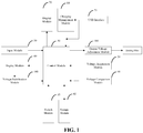
- an intelligent controller includes a switch module 10, a voltage acquisition module 20, a control module 30, a display module 40, a battery (not shown), an input module 50, a storage module 60, a USB interface 70, a charging management module 80, a voltage comparison module 90, a voltage stabilization module 100 and an output voltage adjustment module 110 .
- a switch module 10 a voltage acquisition module 20, a control module 30, a display module 40, a battery (not shown), an input module 50, a storage module 60, a USB interface 70, a charging management module 80, a voltage comparison module 90, a voltage stabilization module 100 and an output voltage adjustment module 110 .
- the switch module 10 is electrically connected with the control module 30, and the control module 30 detects whether the intelligent controller should be activated according to a high voltage signal from the switch module 10 .
- the switch module 10 is preferably a key-pressing switch K1.
- the first mode is that when the switch module 10 has been switched on five times in a row for a set period of time in a shutdown condition, the intelligent controller may be activated if the control module 30 detects the continuous high voltage signals from the switch module 10, and the control module 30 outputs the menu to the display module.
- the second mode is that the user selects the start option in the menu after the intelligent controller is activated, and under this option, the intelligent controller is in a standby state ready for smoking.
- the control module 30 When the user sends a high voltage signal to the control module 30 by switching on the switch module 10 one time, the control module 30 outputs a control signal to make the battery supply power to the heating wire 120 after receiving the high voltage signal, and during the process, the control module 30 may record a start time for operating (a specific point of time to start to switch on the switch module 10 ), an operating time (the length of time for the switch module 10 being switched on), resistance of the heating wire 120 and so on.
- the intelligent controller outputs current to the heating wire 120 so that the heating wire 120 may be heated, this should be considered as one whiff regardless of actually smoking of the electronic cigarette by the user (the nicotine liquid may be introduced from the smoke cartridge to the heating wire 120 by the negative pressure created by the smoking of the user, and the nicotine liquid may be atomized by the heat from the heating wire 120 ).That is, once there is a current flowing to the heating wire 120 the event may be considered as a smoking by the user, regardless if the nicotine liquid reaches the atomizer and is atomized by the heating wire 120 of the atomizer.
- the above description shows two important functions of the switch module 10 . One is to activate the intelligent controller, and the other is to use as an actual operation of smoking in the state of power-on.
- the switch module 10 also has a function of switching between the start options and the menu. For example, when the electronic cigarette is in the smoking mode, if the user switches on the switch module 10 five times in a set period of time, the control module 30 will switch the current interface to the menu interface.
- the voltage acquisition module 20 is coupled to a heating wire 120, configured to acquire a terminal voltage of the heating wire 120 .
- the voltage acquisition module 20 comprises a first transistor Q3, a second transistor Q4, a first resistor R13 and a second resistor R4.
- the base of the first transistor Q3 is coupled to the control module 30, a voltage division and filter circuit is connected between the first transistor Q3 and the control module 30, the voltage division and filter circuit comprises a capacitor C5, a resistor R21 and a resistor R23, one end of the resistor R23 is connected in parallel with one end of the resistor R21 and then in series with the capacitor C5, the other end of the resistor R21 is connected to the base of the first transistor Q3, and the other end of the resistor R23 is connected to the ground.
- the emitter of the first transistor Q3 is connected to the ground, the collector of the first transistor Q3 is connected to the base of the second transistor Q4, and the collector of the first transistor Q3 is coupled to the base of the second transistor Q4 via the resistor R12.
- the collector of the first transistor Q3 and the emitter of the second transistor Q4 are both connected to the battery.
- the collector of the second transistor Q4 is connected to one end of the first resistor R13, the other end of the first resistor R13 is connected to one end of the second resistor R4, the other end of the second resistor R4 is a coupling end for the heating wire 120 of the atomizer of the electronic cigarette.
- the heating wire 120 is connected between the second resistor R4 and the ground, and both ends of the second resistor are coupled to the control module 30, in order to send the acquired result to the control module 30 .
- a voltage division and filter circuit is connected to both ends of the second resistor R4, which comprises a resistor R 30, a resistor R31, a resistor R33, a resistor R34, a capacitor C23 and a capacitor C24.
- the voltage acquisition module 20 is operated as follows: when the switch module 10 has been continuously switched on five times in 1.5 seconds, the control module 30 will detect the condition of the heating wire 120 at first, and the detection includes: a control pin PC6 of the control module 30 sends a control signal to turn on the first transistor Q3 and the second transistor Q4 in turn, and the current of the battery flows through the second transistor Q4 and flows through the first resistor R13 and the second resistor R4 in turn.
- the control module 30 can detect the heating wire 120 is in a short-circuit condition after acquiring that the voltage of the end of the second resistor R4 connected to the heating wire 120 is zero. If the heating wire 120 is in an open-circuit condition, there is no current flowing through the circuit, both ends of the second resistor R4 have a same voltage, and the control module 30 can detect that the heating wire 120 is in an open-circuit condition after acquiring that both ends of the second resistor R4 have a same voltage.
- the control module 30 can calculate the resistance value of the heating wire 120.
- the control module 30 may be a control device, such as a microcontroller or a digital signal processor (DSP).
- the control module 30 is configured to send a control signal to the voltage acquisition module 20 to make the voltage acquisition module 20 acquire a terminal voltage of the heating wire 120, after receiving the high voltage signal from the switch module 10, detect whether the heating wire 120 of an atomizer is in a short-circuit condition, an open-circuit condition or a normal condition, according to the type of the acquired signal from the voltage acquisition module 20, and output a detection result.
- An electronic cigarette menu is built in the control module 30, and parameters of electronic cigarette are stored in the control module 30 .
- the control module 30 digitally outputs the electronic cigarette menu and the parameters after the intelligent controller is activated.
- the display module 40 is electrically connected to an output of the control module 30 .
- the display module 40 is configured to digitally display whether the heating wire 120 is in a short-circuit condition, an open-circuit condition or a normal condition for users to observe the current condition of the heating wire 120 directly.
- the display module 40 is also configured to digitally display the electronic cigarette menu and the parameters for users to observe the active state of the electronic cigarette.
- the display module 40 includes a switching voltage booster U2 coupled to the control module 30 .
- the switching voltage booster U2 outputs a voltage after acquiring a control signal output from the control module 30 .
- the switching voltage booster U2 may be a TPS6 1040 chip.
- the display module 40 also includes a display screen (not shown) coupled to an output of the switching voltage booster, configured to display the electronic cigarette menu and the values of the parameters of the electronic cigarette output from the control module 30 after acquiring the output voltage of the switching voltage booster.
- the display screen is an OLED display screen.
- the switching voltage booster U2 supplies necessary power to the display screen, for example, via a 28 pins interface.
- the display screen provides visualized operations in man-machine interaction, to improve operating convenience and bring higher intelligence.
- the input module 50 is electrically connected to an input of the control module 30 .
- the user sends a signal to the control module 30 to select options in the electronic cigarette menu via the input module 50 , and sends instructions to the control module 30 to adjust the parameters after viewing the parameters of the electronic cigarette, wherein the corresponding parameters are adjusted by the control module 30 .
- the storage module 60 is coupled to an output of the control module 30 .
- the control module 30 stores data produced during smoking in the storage module 60 .
- the input module includes a switch S2. The first switch end and the second switch end of the switch are coupled to the control module 30, respectively.
- the switch S2 is a single-pole double-throw switch, with an advantage that the switch can be driven by a knob such that the single-pole double-throw switch can be switched on to send a signal to the control module 30 when the knob rotates in any direction, which provides operating convenience for users.
- the parameters in the control module 30, such as time, date and maximum number of whiffs of one day, can be modified, which improves man-machine interaction and brings higher intelligence to users.
- the storage module 60 is a flash memory with a serial peripheral interface.
- the storage module 60 is an external memory of the control module 30 .
- the control module 30 can obtain the parameters of the state of the smoking based on an internal real time clock (RTC).
- RTC real time clock
- the parameters of the current state are stored in the storage module 60 . Every whiff (the switch module 10 is switched on once in the state of power-on) will cause a piece of data containing the above information stored in the storage module 60 .
- the data can be provided to a PC via a corresponding interface for analysis and the statistics.
- the data stored in the storage module 60 also can be fetched to the display module 40 via the input module for users to observe.
- the battery (not shown) is electrically connected to the switch module 10, the voltage acquisition module 20, the control module 30 and the display module 40, respectively, and supplies working voltages to the switch module 10, the voltage acquisition module 20, the control module 30 and the display module 40, respectively.
- the battery also supplies working voltages to the charging management module 80, the voltage comparison module 90, the voltage stabilization module 100 and the output voltage adjustment module 110.
- the USB interface 70 (J4 in FIG. 8 ) is electrically connected to the control module 30 .
- the USB interface 70 is configured to use as an interface for data interaction between the control module 30 and an intelligence terminal device.
- the USB interface 70 is also coupled to a charging management module 80 which is also coupled to the control module 30 and the battery.
- the control module 30 can communicate with the intelligence terminal device through the USB interface 70 coupled to the intelligence terminal device, to send the data stored in the storage module 60 and produced during smoking to the intelligence terminal device.
- the intelligence terminal device can carry out a further analysis on the data, so the user can see the service conditions of the electronic cigarette more intuitively.
- the service conditions include daily conditions, weekly conditions and monthly conditions. These service conditions can be displayed on the intelligence terminal device in forms of graphs.
- the USB interface 70 can transmit the voltage of the external power to the charging management module 80 (U6 in FIG.8 ), and the battery can be recharged via the charging management module.
- the charging management module 80 can be a BQ24040 chip, the pin 1 of the chip is coupled to the output of the USB interface 70, the pin 10 of the chip is coupled to the battery, and the pin 8 of the chip is coupled to the control module 30 .
- the voltage comparison module 9 is coupled to the control module 30 .
- the voltage comparison module 9 compares an acquired voltage of the battery with a reference voltage to obtain a voltage difference, amplifies the voltage difference after comparing, and sends the amplified voltage difference to the control module 30 .
- the voltage comparison module 9 comprises a MCP6001chip and a peripheral circuit.
- the voltage comparison module 9 can compare the voltage of the battery with the reference voltage of 1.8V, amplify the voltage difference after comparing, and send the amplified voltage difference to an AD sampling interface, so that the control module 30 can obtain a precise voltage of the battery.
- the voltage comparison module 9 offsets the lack of precision of the AD sampling interface of the control module 30 .
- the voltage of the battery can be output to the display module 40 via the control module 30, so that users can know the voltage of the battery accurately when the intelligent controller is at work.
- the voltage stabilization module 100 is coupled to an output of the switching voltage booster U2.
- the voltage stabilization module 100 converts the voltage from the switching voltage booster and provides a stable voltage to the control module 30 .
- the voltage stabilization module 100 is a XC620P332M chip. Because the intelligent controller according to the present invention has a high current (greater than 1A) at work, there is a great voltage drop in the battery, and when the voltage of the battery is low, the voltage drop can cause the voltage of the battery too low, making the control module 30 reset.
- the function of the voltage stabilization module 100 is to generate a steady voltage of 3.3V to power the control module 30, so as to avoid the problem of the reset of the control module 30 when the heating wire 120 is at work. If there is no voltage stabilization module 100 in the intelligent controller according to the present invention, the control module 30 can be reset when the battery operates at about 3.6V. Because of the voltage stabilization module 100, the intelligent controller will still work even if the voltage of the battery is decreased to 3.3V or below.
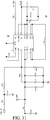
- the output voltage adjustment module 110 is coupled to the control module 30, configured to adjust a voltage output from the output voltage adjustment module 110 to the heating wire 120 of the electronic cigarette to a voltage defined by a user, according to a pulse width modulation signal output from the control module 30 based on a signal for adjusting the output voltage from the input module.
- the output voltage adjustment module 110 includes a switching buck-boost converter U1, a switch pin of the switching buck-boost converter is coupled to an output of the control module 30, and a reference voltage pin of the switching buck-boost converter is coupled to an output of the pulse width modulation signal of the control module 30 .
- the control module 30 When the control module 30 detects that the heating wire 120 is in a normal condition, the user can define the output voltage by the input module. Because the voltage of the reference voltage pin 12 of the switching buck-boost converter U1 is constant at 0.5V, and the output voltage of the pin 4 of the switching buck-boost converter U1 can be changed by a pulse width modulation signal to make the voltage of the pin 3 stabilize at 0.5V, the output voltage of the switching buck-boost converter U1 can be changed by the pulse width modulation signal output from the control module 30 according to the voltage signal input defined by the user.
- the electronic cigarette includes an atomizer, a smoke cartridge and the above intelligent controller for electronic cigarette.
- the intelligent controller is coupled to the atomizer.
- the electronic cigarette works as follows: when the switch module 10 has been switched on five times in a row for a set period of time in a shutdown mode, the intelligent controller may be activated if the control module 30 detects the continuous high voltage signals from the switch module 10, and the control module 30 outputs the menu to the display module 40 .
- the user selects the start option in the menu (other options can be selected to view, set or modify the parameters) after the intelligent controller is activated, and under this option, the intelligent controller is in a standby state ready for smoking.
- the control module 30 When the user sends a high voltage signal to the control module 30 by switching on the switch module 10 one time, the control module 30 outputs a control signal to make the battery supply power to the heating wire 120 after receiving the high voltage signal, the nicotine liquid in the smoke cartridge is introduced to the atomizer by the negative pressure created by the smoking of the user, the nicotine liquid is atomized by the atomizer, and the smoke produced reaches the mouth of the user.
- the control module 30 may record a start time for operating (a specific point of time to start to switch on the switch module 10), an operating time (a length of time for the switch module 10 being switched on), resistance of the heating wire 120 and so on, and the intelligent controller outputs current to the heating wire 120 such that the heating wire 120 may be heated.
- the special nature of the electronic cigarette according to the present invention is that this should be considered as one whiff regardless of actually smoking of the electronic cigarette for the user (the nicotine liquid may be introduced from the smoke cartridge to the heating wire 120 by the negative pressure created by the smoking of the user, and the nicotine liquid may be atomized by the heat from the heating wire 120 ). That is, once there is a current flowing to the heating wire 120, the event may be considered as a smoking by the user, regardless if the nicotine liquid reaches the atomizer and is atomized by the heating wire 120 of the atomizer.
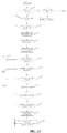
- an intelligent control method of an electronic cigarette includes:
- Step S1 sending, by a switch module 10, a high voltage signal of startup to a control module 30, wherein the way to send a valid activating signal from the switch module 10 by sending a high voltage signal is by switching on the switch module 10 B times in A second(s), and the time for one switching on is less than C second(s).
- Step S11 detecting, by the control module 30, whether the voltage of the battery is larger than N volt, if the result of the detection is no, enter a standby state, and if the result of the detection is yes, proceeding to S2.
- the electronic cigarette may only be used when the capacity of the battery is larger than a certain value, which helps to ensure sufficient atomization during use and life of the battery.
- Step S2 receiving, by the control module 30, the high voltage signal of startup from the switch module 10, sending a control signal to a voltage acquisition module 20 to make the voltage acquisition module 20 acquire a terminal voltage of the heating wire 120, detecting whether the heating wire 120 of an atomizer is in a short-circuit condition, an open-circuit condition or a normal condition, according to the type of an acquired signal from the voltage acquisition module 20, and outputting a detection result.
- a built-in electronic cigarette menu in the control module 30 can be output to the display module 40, while the condition of the heating wire 120 of the atomizer that the heating wire 120 is in a short-circuit condition, an open-circuit condition or a normal condition is output to the display module 40 .
- step S3 digitally displaying, by a display module 40, an output signal from the control module 30 to show whether the heating wire 120 is in a short-circuit condition, an open-circuit condition or a normal condition, and displaying by the display module 40 the electronic cigarette menu, in order to let the users observe the current condition of the heating wire 120 directly.
- Step S4 selecting, via an input module, start options in the menu, viewing parameter values in other options in the menu, or sending a signal to the control module 30 to adjust the parameter, wherein, the control module 30 can adjust the corresponding parameter values after receiving the signal for adjustment from the input module, and output the adjusted parameter values to the display module 40 for display.
- Step S5 if the control module 30 does not detect a high voltage signal from the switch module 10 for one switching on in D second(s), the control module 30 controlling the intelligent controller to enter a standby state, and if the control module 30 detect a high voltage signal from the switch module 10 for one switching on in D second(s), then proceeding to S51.
- Step S51 detecting, by the control module 30, whether the capacity of the battery is larger than 0%, if the result of the detection is no, proceeding to perform a shutdown, and if the result of the detection is yes, proceeding to step S52.
- Step S52 parameters of the electronic cigarette in the control module 30 include the parameter of the maximum number of whiffs of one day, the control module 30 detects whether the number of whiffs of the day reaches the maximum number of whiffs, if the detected result of S52 is yes, then the control module 30 controls the intelligent controller to enter a standby state, and if the detected result of S51 is no, then proceeding to S6.
- Step S6 the control module 30 controlling a voltage adjustment module to supply power to a load such that the user can smoke the electronic cigarette. After supplying power to the load of step S6, perform the step S11.
- Step S7 detecting, by the control module 30, whether the switch module 10 is switched off, if the result of the detection is yes, the intelligent controller enters the standby state, and if the result of the detection is no, proceeding to step S8.
- Step S8 detecting, by the control module 30, whether the switch module 10 is switched on for F second(s), if the result of the detection is no, the intelligent controller enters the standby state, and if the result of the detection is yes, proceeding to step S9.
- Step S9 outputting, by the control module 30, a control signal to stop supplying power to the load and the intelligent controller enters a standby state.
- Step S 10 in the standby state, if the control module 30 does not detect a high voltage signal from the switch module 10 used for any switching on, the intelligent controller enters a sleep state to wait to be woken up by a high voltage signal from the switch module 10 to the control module 30 .
- An intelligent controller of an electronic cigarette includes a switch module, configured to send a high voltage signal to activate the intelligent controller; a voltage acquisition module coupled to a heating wire of an atomizer, configured to acquire a terminal voltage of the heating wire; a control module coupled to the switch module and the voltage acquisition module, respectively, configured to send, after receiving the high voltage signal from the switch module, a control signal to the voltage acquisition module to make the voltage acquisition module acquire a terminal voltage of the heating wire, detect whether the heating wire is in a short-circuit condition, an open-circuit condition or a normal condition based on a type of the acquired signal from the voltage acquisition module, and output a detection result; a display module electrically connected to an output of the control module, configured to digitally display whether the heating wire is in a short-circuit condition, an open-circuit condition, or a normal condition, such that a user directly observes condition of the heating wire; and a battery electrically connected to the switch module, the voltage acquisition module, the control module, and the display module, respectively, configured to
- the control module stores a built-in electronic cigarette menu and stores parameters of an electronic cigarette.
- the intelligent controller further includes an input module electrically connected to an input of the control module, wherein the user, via the input module, sends instructions to the control module to select options from the electronic cigarette menu, sends instructions to the control module to adjust parameters after viewing the parameters of the electronic cigarette, and the control module adjusts the corresponding parameters; and a storage module coupled to an output of the control module, wherein the control module is configured to store data produced by the intelligent controller to the storage module.
- the intelligent controller of an electronic cigarette further includes a Universal Serial Bus (USB) interface electrically connected to the control module, wherein the USB interface is configured to be used as an interface for data interaction between the control module and an intelligence terminal device.
- USB Universal Serial Bus
- the intelligent controller of an electronic cigarette further includes a charging management module coupled to the USB interface, wherein the charging management module is electrically connected to the control module and the battery, respectively.
- the intelligent controller of an electronic cigarette further includes a voltage comparison module, wherein the voltage comparison module is configured to compare an acquired voltage of the battery with a reference voltage to obtain a voltage difference, amplify the voltage difference after comparing, and send the amplified voltage difference to the control module.
- the intelligent controller of an electronic cigarette further includes a display module, wherein the display module comprises: a switching voltage booster coupled to the control module, and configured to boost the voltage of the battery to output after acquiring the output signal of the control module; and a display screen coupled to an output end of the switching voltage booster, configured to display the condition of the heating wire output from the control module after acquiring the output voltage of the switching voltage booster.
- the display module comprises: a switching voltage booster coupled to the control module, and configured to boost the voltage of the battery to output after acquiring the output signal of the control module; and a display screen coupled to an output end of the switching voltage booster, configured to display the condition of the heating wire output from the control module after acquiring the output voltage of the switching voltage booster.
- the intelligent controller of an electronic cigarette further includes a voltage stabilization module coupled to an output of the switching voltage booster, wherein the voltage stabilization module is configured to convert the voltage from the switching voltage booster and provide a stable voltage to the control module.
- the intelligent controller of an electronic cigarette further includes an output voltage adjustment module coupled to the control module, wherein the control module outputs a pulse width modulation signal based on a signal from the input module for adjusting the output voltage of the output voltage adjustment module that is provided to the heating wire of the electronic cigarette to a voltage value defined by the user.
- the output voltage adjustment module includes a switching buck-boost converter, wherein a switch pin of the switching buck-boost converter is coupled to an output of the control module, and a reference voltage pin of the switching buck-boost converter is coupled to an output of the control module outputting the pulse width modulation signal.
- a method for intelligently controlling an electronic cigarette includes:
- step S2 a built-in electronic cigarette menu in the control module is output to the display module, while whether the heating wire is in a short-circuit condition, an open-circuit condition, or a normal condition is output to the display module, and when the electronic cigarette menu is displayed by the display module in the step S3, a following step is executed: step S4, selecting, via an input module, start options in the menu, viewing parameter values in other options in the menu, or sending a signal to the control module to adjust the parameter values, wherein the control module adjust the corresponding parameter values after receiving the signal for adjustment from the input module, and outputs the adjusted parameter values to the display module for display.
- the method further includes:
- the switch module When the switch module is switched on B times in A second(s) and when time for one switch-on is less than C second(s), the high voltage signal sent from the switch module is determined to be a valid activating signal.
- the method for intelligently controlling an electronic cigarette further includes:
- the method further includes:
- the method further comprises: step S51, detecting, by the control module, whether a capacity of the battery is greater than 0%, if the result of the detection is no, proceeding to perform a shutdown, and if the result of the detection is yes, proceeding to the step S6.
- Parameters of the control module of the electronic cigarette include a maximum number of whiffs of one day, and between the steps S51 and S6, the method further comprises a step S52 of detecting whether number of whiffs of the day reaches the maximum number of whiffs, if the detected result of S52 is yes, then the control module controls the intelligent controller to enter a standby state, and if the detected result of S52 is no, then proceeding to S6.
- the method further comprises:
- the method for intelligently controlling an electronic cigarette further includes a step S10 wherein in the standby state, if the control module fails to detect the high voltage signal from the switch module for a switch-on, the intelligent controller enters a sleep state to wait to be woken up by another high voltage signal from the switch module to the control module.
- An electronic cigarette includes an intelligent controller comprising a switch module, a voltage acquisition module, a control module, a display module, and a battery; wherein the switch module is configured to send a high voltage signal to activate the intelligent controller; wherein the voltage acquisition module is coupled to a heating wire and configured to acquire a terminal voltage of the heating wire; wherein the control module is coupled to the switch module and the voltage acquisition module, respectively, and is configured to, after receiving the high voltage signal from the switch module, send a control signal to the voltage acquisition module to make the voltage acquisition module acquire a terminal voltage of the heating wire, detect whether the heating wire is in a short-circuit condition, an open-circuit condition, or a normal condition based on a type of the acquired signal from the voltage acquisition module, and output a detection result; wherein the display module is electrically connected to an output of the control module and is configured to digitally display whether the heating wire is in a short-circuit condition, an open-circuit condition, or a normal condition, such that a user can directly observe a condition
Description
- The present invention relates generally to an electronic cigarette, and more particularly, to an intelligent controller and a method of the electronic cigarette.
- An electronic cigarette includes a battery, a control circuit, and an atomizer. When a user inhales, a high speed airflow is formed in an airflow sensor which senses the inhaling from the user's mouth to actuate an airflow sensor switch to turn on the airflow sensor switch, and the electronic cigarette enters the working status. A control module of the control circuit can control an execution unit to operate by calculating and measuring. The atomizer can be controlled by the control module, and achieve different degrees of atomization according to degrees of suction from the mouth. The atomizer includes a high frequency oscillation circuit and a heating wire. In the atomizer, a nicotine liquid with high purity can be pressurized by a superfine atomizing pump, then enters into an atomizing chamber to be critically atomized into droplets with sizes of about 0. 5- 1.5 µm, to be dissipated in forms of aerosols by mixing with the inhaled airflow, and form vapors that simulate a smoke gas and have an appearance similar to smoke, but is actually a fog. The condition for critical atomizing is that a surface tension of the liquid is reduced by heating to a degree that it is easiest for the liquid to be atomized, and a temperature of a normal smoke gas (50-60 degree centigrade) is simulated while the smoke fog is simulated. At the same time, an indicator light at a front section of the electronic cigarette can be illuminated to simulate light of the cigarette tip to indicate that the electronic cigarette is in operation. When the inhaling is halted, the airflow in the sensor disappears, the airflow sensor switch is turned off, the control module of the control circuit stops working, the atomizer stops working, and the indicator light at the front section of the electronic cigarette is turned off.
- When an electronic cigarette has been used for a period of time, there may be failures if the nicotine liquid cannot be atomized into vapors. Because the user cannot visually observe where the trouble spot is, the user cannot repair the defect by himself. Thus, the user has to abandon the electronic cigarette or send the electronic cigarette to an after-sale service station of the vendor for overhauling. After checking, it may be determined that the heating wire is in circumstances of short circuit or open circuit. Such minor failure causing the electronic cigarette to malfunction will affect the user's degree of trust in the electronic cigarette.
-
CN102727969A discloses a method for intelligently controlling an electronic cigarette, comprising: step S1, sending, by a switch module, a signal of startup to a control module; and step S2, receiving, by the control module, the signal of startup from the switch module. - In view of the above, an objective of the present invention is to provide an intelligent controller of an electronic cigarette, by which certain conditions, including a normal condition, a short-circuit condition, or an open-circuit condition, of a heating wire of an atomizer of the electronic cigarette can be directly observed by a user,
- According to an embodiment, an electronic cigarette, comprises: an intelligent controller comprising a switch module, a voltage acquisition module, a control module, and a display module;
wherein the switch module is configured to send a high voltage signal to activate the intelligent controller;
wherein the voltage acquisition module is adapted for being coupled to a heating wire of an atomizer, configured to acquire a terminal voltage of the heating wire;
wherein the control module is coupled to the switch module and the voltage acquisition module, respectively, and is configured to send, after receiving the high voltage signal from the switch module, a control signal to the voltage acquisition module to make the voltage acquisition module acquire the terminal voltage of the heating wire, detect whether the heating wire is in a short-circuit condition, an open-circuit condition or a normal condition based on a type of the acquired signal from the voltage acquisition module, and output a detection result;
wherein the display module is electrically connected to an output of the control module, and is configured to digitally display whether the heating wire is in a short-circuit condition, an open-circuit condition, or a normal condition, such that a user directly observes condition of the heating wire. - By adopting the above embodiment, when the control module receives the signal from the switch module to activate the intelligent controller, the control module sends a control signal to drive the voltage acquisition module to acquire the terminal voltage of the heating wire; the voltage acquisition module sends the acquired signal to the control module; the control module detects whether the heating wire is in a short-circuit condition, an open-circuit condition or a normal condition, according to the type of the acquired signal from the voltage acquisition module, and outputs the detection result, and the display module displays whether the heating wire is in a short-circuit condition, an open-circuit condition, or a normal condition for a user to observe the current condition of the heating wire directly. If there is a failure with the heating wire, the user can know the condition of the heating wire with the intelligent controller directly according to the present invention, and a small failure, such as a short circuit or an open circuit of the heating wire, can be resolved by a simple repair by the user, avoiding the adverse effect of abandoning the electronic cigarette, and thereby ensuring the trust of users in the electronic cigarette. In addition, compared with the control circuit of prior art electronic cigarettes, the intelligent controller with the above fault detection according to the present invention has an advantage of high-degree intelligence.
- Preferably, the control module can be a control module storing a built-in electronic cigarette menu and storing parameters of the electronic cigarette. According to an embodiment, the intelligent controller also includes:
- an input module electrically connected to an input of the control module, via which a user sends instructions to the control module to select options in the electronic cigarette menu, and sends instructions to the control module to adjust the parameters after viewing the parameters of the electronic cigarette, wherein the corresponding parameters are adjusted by the control module; and
- a storage module coupled to an output of the control module, configured to store data produced during smoking via the control module. According to the present invention, after the intelligent controller is activated by the switch module, the built-in electronic cigarette menu can be output, and the display module displays the electronic cigarette menu in the control module for the user to visually observe the condition of the electronic cigarette, after obtaining a control signal from the control module. The user can select start options in the menu or view parameter values in other options in the menu via the input module, or send a signal to the control module via the input module to adjust the parameter values. The control module can adjust corresponding parameter values after receiving the signal for adjustment from the input module, and output the adjusted parameter values to the display module for display.
- According to the present invention, parameters can be set or adjusted via the input module after the intelligent controller is activated, and such adjustable parameters include time, date, maximum number of whiffs of one day, cumulative number of whiffs, and so on. The above parameters can be set or adjusted by a user according to his own need, so the intelligent controller according to the present invention has an advantage of high-degree intelligence.
- Preferably, the intelligent controller further includes a Universal Serial Bus (USB) interface electrically connected to the control module, configured to use as an interface for data interaction between the control module and an intelligence terminal device. The control module can communicate with the intelligence terminal device through the USB interface coupled to the intelligence terminal device, to send the data stored in the storage module and produced during smoking to the intelligence terminal device. The intelligence terminal device can carry out a further analysis on the data, so the user can see the service conditions of the electronic cigarette more intuitively. The service conditions can include daily condition, weekly condition and monthly condition. These service conditions can be displayed on the intelligence terminal device in the form of graphs.
- Preferably, the intelligent controller further includes a charging management module coupled to the USB interface, and electrically connected to the control module and the battery, respectively. When an external power is connected to the USB interface, the USB interface can transmit the voltage of the external power to the charging management module, and the battery can be recharged via the charging management module. Therefore, in addition to an interface for communication, the intelligent controller according to the present invention also has an interface for charging.
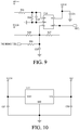
- Preferably, the intelligent controller further includes a voltage comparison module, configured to compare an acquired voltage of the battery with a reference voltage to obtain a voltage difference, amplify the voltage difference after comparing, and send the amplified voltage difference to the control module. The voltage comparison module can compare the voltage of the battery with the reference voltage of 1.8V, amplify the voltage difference after comparing, and send the amplified voltage difference to an AD sampling interface, so that the control module can obtain a precise voltage of the battery. The voltage comparison module offsets the lack of precision of the AD sampling interface of the control module. The voltage of the battery can be output to the display module via the control module, so that the user can know the voltage of the battery accurately when the intelligent controller is at work.
- Preferably, the display module includes:
- a switching voltage booster coupled to the control module, configured to boost the voltage of the battery to output after acquiring the output signal of the control module; and
- a display screen coupled to an output of the switching voltage booster, configured to display the condition of the heating wire output from the control module after acquiring the output voltage of the switching voltage booster.
- In the intelligent controller according to a preferred embodiment of the present invention, the display screen can be an OLED display screen, wherein the display screen requires a high voltage at work Thus, boosting the voltage of the battery via the switching voltage booster can meet the voltage requirement of the display screen.
- Preferably, the intelligent controller further includes a voltage stabilization module coupled to an output of the switching voltage booster, configured to convert the voltage from the switching voltage booster and provide a stable voltage to the control module. Because the intelligent controller according to the present invention has a high current (greater than 1A) at work, there is a great voltage drop in the battery, and when the voltage of the battery is low, the voltage drop can cause the voltage of the battery to be too low, making the control module reset. The function of the voltage stabilization module is to generate a steady voltage of 3.3V to power the control module, so as to avoid the problem of the reset of the control module when the heating wire is at work. If there is no voltage stabilization module in the intelligent controller according to the present invention, the control module can be reset when the battery operates at about 3.6V. Because of the voltage stabilization module, the intelligent controller will still work even if the voltage of the battery is decreased to 3.3V or below.
- Preferably, the intelligent controller further includes an output voltage adjustment module coupled to the control module, configured to adjust a voltage output from the output voltage adjustment module to the heating wire of the electronic cigarette to a voltage defined by a user, according to a pulse width modulation signal output from the control module based on a signal for adjusting the output voltage from the input module. After startup of the intelligent controller according to the present invention, users can make the decision whether or not the voltage should be adjusted, based on the voltage displayed on the display module and their practical demands. The detailed process of the adjustment is that the input module is operated to send a user-defined voltage signal, the control module calculates and sends a pulse width modulation signal to the output voltage adjustment module after receiving the user-defined voltage signal, and the voltage output from the output voltage adjustment module can be adjusted to the voltage defined by the user. The intelligent controller according to the present invention can adjust the output voltage within a given voltage range, and it offers advantages that it can avoid a situation that the temperature of the heating wire is not high enough to make the nicotine liquid be atomized completely, so as to get the best effect of smoking experience; and it can avoid the burning out of the heating wire caused by the heating wire withstanding a large voltage or current.
- Also described herein is an intelligent control method for electronic cigarette, comprising:
- step S1, sending, by a switch module, a high voltage signal of startup to a control module;
- step S2, receiving, by the control module, the high voltage signal of startup from the switch module, sending a control signal to a voltage acquisition module to make the voltage acquisition module acquire a terminal voltage of the heating wire, detecting whether the heating wire of an atomizer is in a short-circuit condition, an open-circuit condition, or a normal condition, according to the type of the acquired signal from the voltage acquisition module, and outputting a detection result; and
- step S3, digitally displaying, by a display module, an output signal from the control module to show whether the heating wire is in a short-circuit condition, an open-circuit condition, or a normal condition, such that a user directly observes the condition of the heating wire; wherein in the step S2, a built-in electronic cigarette menu in the control module is output to the display module, while whether the heating wire is in a short-circuit condition, an open-circuit condition, or a normal condition is output to the display module, and when the electronic cigarette menu is displayed by the display module in the step S3, a following step is executed:
step S4, selecting, via an input module, start options in the menu, viewing parameter values in other options in the menu, or sending a signal to the control module to adjust the parameter values, wherein the control module adjusts the corresponding parameter values after receiving the signal for adjustment from the input module; wherein in the step S4, if an option of booting in the menu is selected, the method further comprises:- step S5, if the control module fails to detect the high voltage signal from the switch module for one switch-on in D second, the control module controlling an intelligent controller of the electronic cigarette to enter a standby state, and if the control module detects the high voltage signal from the switch module for one switch-on in D second, then proceeding to a step S6; and
- step S6, the control module controlling a voltage adjustment module to supply power to the heating wire of the atomizer such that the electronic cigarette starts to be smoked.
- By adopting the above embodiments, when the control module receives a signal from the switch module to activate the intelligent controller, the control module sends a control signal to make the voltage acquisition module acquire the terminal voltage of the heating wire, the voltage acquisition module sends the acquired signal to the control module, the control module detects whether the heating wire is in a short-circuit condition, an open-circuit condition, or a normal condition, according to the type of the acquired signal from the voltage acquisition module, and output the detection result; and the display module displays whether the heating wire is in a short-circuit condition, an open-circuit condition, or a normal condition for users to observe the current condition of the heating wire directly. If there is a failure in the heating wire, users can know the condition of the heating wire via the intelligent controller directly according to the present invention, and a minor malfunction, such as a short circuit or an open circuit of the heating wire, can be resolved by a simple repair by the users, avoiding the adverse effect of abandoning the electronic cigarette, and thereby ensuring the trust of users in the electronic cigarette. In addition, compared with the control circuit of prior art electronic cigarettes, the intelligent controller with the above fault detection according to the present invention has an advantage of high-degree intelligence.
- The options in the menu displayed can include: booting up; making the device enter a low-power standby state; reading the capacity of the battery; the time for the screensaver to show; the delay time for making the device enter a low-power standby state; checking and setting the time; checking the cumulative number of whiffs of the device, setting a maximum limit for the number of whiffs per day, and resetting the current number of whiffs; and viewing information of the device including resistance of the heating wire, user information, and the device's serial number. If the user selects the option of booting up to make the intelligent controller enter booting up mode, the intelligent controller can return to the menu interface to select from the rest of the options via a five-time-switching-on of the switch module of step S1. If the user selects to boot up the intelligent controller, LOGO of the vendor, calendar, and main interface are displayed on the display module in a sequence. The information presented on the main interface includes current number of whiffs, remaining number of whiffs, the remaining capacity of the battery, output voltage, and indicating arrow for adjustment of the voltage output.
- After the booting up of the intelligent controller, there are two choices when entering into the menu, one is for viewing or changing parameters, the other is to start up to enter a smoking operation. When entering the smoking operation, the switch module should be switched on, and the control module only needs to send a control signal to make the battery supply power to the heating wire of the atomizer when receiving a high voltage signal from the switch module for one switching on.
- Preferably, after the step of S5, the method further comprises: step S51, detecting, by the control module, whether a capacity of a battery for supplying power to the intelligent controller is greater than 0%, if the result of the detection is no, proceeding to perform a shutdown, and if the result of the detection is yes, proceeding to the step S6.
- Preferably, parameters of the electronic cigarette in the control module include the parameter of the maximum number of whiffs of one day, so between the step S51 and S6, it further includes a step S52 of detecting whether the number of whiffs of the day reaches the maximum number of whiffs, if the detected result of S51 is yes, then the control module controls the intelligent controller to enter a standby state, and if the detected result of S51 is no, then proceeding to S6. If the number of whiffs of the day reaches the maximum number of whiffs of one day, the electronic cigarette will no longer permit the user to smoke and automatically enter the standby state, and the user can check the parameters of the electronic cigarette through operations, thus it helps to ensure the user's health.
- Preferably, after supplying power to the load of step S6, it further includes:
- step S7, detecting, by the control module, whether the switch module is switched off, if the result of the detection is yes, the intelligent controller entering the standby state, and if the result of the detection is no, proceeding to step S8;
- step S8, detecting, by the control module, whether the switch module is switched on for F second(s), if the result of the detection is no, the intelligent controller entering the standby state, and if the result of the detection is yes, proceeding to step S9; and
- step S9, outputting, by the control module, a control signal to stop supplying power to the load.
- When the battery supplies power to the heating wire for extended periods, it is not beneficial for saving the capacity of the battery and it is unable to guarantee the life of the heating wire, so it is beneficial to save the capacity of the battery and guarantee the life of the heating wire by controlling the maximum power supply time of the battery by step S8.
- Preferably, the method further includes a step S10 that in the standby state, if the control module does not detect a high voltage signal from the switch module for any one switching on, the intelligent controller enters a sleep state to wait to be woken up by a high voltage signal from the switch module to the control module. It is also beneficial to save the capacity of the battery for the intelligent controller by entering the sleep state during the standby state.
-
-
FIG. 1 is a circuit block diagram illustrating an intelligent controller according to one embodiment of the present invention; -
FIG. 2 is a circuit block diagram illustrating a switch module in the intelligent controller ofFIG. 1 according to one embodiment of the present invention; -
FIG. 3 is a circuit block diagram illustrating a voltage acquisition module in the intelligent controller ofFIG. 1 according to one embodiment of the present invention; -
FIG. 4 is a circuit block diagram illustrating a control module in the intelligent controller ofFIG. 1 according to one embodiment of the present invention; -
FIG. 5 is a circuit block diagram illustrating a switching voltage booster of the display module in the intelligent controller ofFIG. 1 according to one embodiment of the present invention; -
FIG. 6 is a circuit block diagram illustrating an input module in the intelligent controller ofFIG. 1 according to one embodiment of the present invention; -
FIG. 7 is a circuit block diagram illustrating a storage module in the intelligent controller ofFIG. 1 according to one embodiment of the present invention; -
FIG. 8 is a circuit block diagram illustrating a connection between the USB interface and the charging management module in the intelligent controller ofFIG.1 according to one embodiment of the present invention; -
FIG. 9 is a circuit block diagram illustrating a voltage comparison module in the intelligent controller ofFIG. 1 according to one embodiment of the present invention; -
FIG. 10 is a circuit block diagram illustrating a voltage stabilization module in the intelligent controller ofFIG. 1 according to one embodiment of the present invention; -
FIG. 11 is a circuit block diagram illustrating an output voltage adjustment module in the intelligent controller ofFIG. 1 according to one embodiment of the present invention; -
FIG. 12 is a schematic diagram illustrating an electronic cigarette according to one embodiment of the present invention; and -
FIG. 13 is a flow diagram illustrating an intelligent control method for electronic cigarette according to one embodiment of the present invention. - Referring to
FIGS. 1-11 , an intelligent controller according to an embodiment of the present invention includes aswitch module 10, avoltage acquisition module 20, acontrol module 30, adisplay module 40, a battery (not shown), aninput module 50, astorage module 60, aUSB interface 70, acharging management module 80, avoltage comparison module 90, avoltage stabilization module 100 and an outputvoltage adjustment module 110. These parts are described in more details below. - Referring to
FIGS. 1 and2 , theswitch module 10 is electrically connected with thecontrol module 30, and thecontrol module 30 detects whether the intelligent controller should be activated according to a high voltage signal from theswitch module 10. Theswitch module 10 is preferably a key-pressing switch K1. There are two modes of operation of theswitch module 10 recognized by thecontrol module 30. The first mode is that when theswitch module 10 has been switched on five times in a row for a set period of time in a shutdown condition, the intelligent controller may be activated if thecontrol module 30 detects the continuous high voltage signals from theswitch module 10, and thecontrol module 30 outputs the menu to the display module. If the high voltage signals produced by switching on the key-pressing switch are not continuous, or the number of the high voltage signals does not reach a setting value, the high voltage signals will be considered to be produced by wrong operations and the intelligent controller cannot be activated. The second mode is that the user selects the start option in the menu after the intelligent controller is activated, and under this option, the intelligent controller is in a standby state ready for smoking. When the user sends a high voltage signal to thecontrol module 30 by switching on theswitch module 10 one time, thecontrol module 30 outputs a control signal to make the battery supply power to the heating wire 120 after receiving the high voltage signal, and during the process, thecontrol module 30 may record a start time for operating (a specific point of time to start to switch on the switch module 10), an operating time (the length of time for theswitch module 10 being switched on), resistance of the heating wire 120 and so on. Because the intelligent controller outputs current to the heating wire 120 so that the heating wire 120 may be heated, this should be considered as one whiff regardless of actually smoking of the electronic cigarette by the user (the nicotine liquid may be introduced from the smoke cartridge to the heating wire 120 by the negative pressure created by the smoking of the user, and the nicotine liquid may be atomized by the heat from the heating wire 120).That is, once there is a current flowing to the heating wire 120 the event may be considered as a smoking by the user, regardless if the nicotine liquid reaches the atomizer and is atomized by the heating wire 120 of the atomizer. The above description shows two important functions of theswitch module 10. One is to activate the intelligent controller, and the other is to use as an actual operation of smoking in the state of power-on. In addition, theswitch module 10 also has a function of switching between the start options and the menu. For example, when the electronic cigarette is in the smoking mode, if the user switches on theswitch module 10 five times in a set period of time, thecontrol module 30 will switch the current interface to the menu interface. - Referring to
FIGS. 1 and3 , thevoltage acquisition module 20 is coupled to a heating wire 120, configured to acquire a terminal voltage of the heating wire 120. Thevoltage acquisition module 20 comprises a first transistor Q3, a second transistor Q4, a first resistor R13 and a second resistor R4. The base of the first transistor Q3 is coupled to thecontrol module 30, a voltage division and filter circuit is connected between the first transistor Q3 and thecontrol module 30, the voltage division and filter circuit comprises a capacitor C5, a resistor R21 and a resistor R23, one end of the resistor R23 is connected in parallel with one end of the resistor R21 and then in series with the capacitor C5, the other end of the resistor R21 is connected to the base of the first transistor Q3, and the other end of the resistor R23 is connected to the ground. The emitter of the first transistor Q3 is connected to the ground, the collector of the first transistor Q3 is connected to the base of the second transistor Q4, and the collector of the first transistor Q3 is coupled to the base of the second transistor Q4 via the resistor R12. The collector of the first transistor Q3 and the emitter of the second transistor Q4 are both connected to the battery. The collector of the second transistor Q4 is connected to one end of the first resistor R13, the other end of the first resistor R13 is connected to one end of the second resistor R4, the other end of the second resistor R4 is a coupling end for the heating wire 120 of the atomizer of the electronic cigarette. The heating wire 120 is connected between the second resistor R4 and the ground, and both ends of the second resistor are coupled to thecontrol module 30, in order to send the acquired result to thecontrol module 30. A voltage division and filter circuit is connected to both ends of the second resistor R4, which comprises a resistor R30, a resistor R31, a resistor R33, a resistor R34, a capacitor C23 and a capacitor C24. Thevoltage acquisition module 20 is operated as follows:
when theswitch module 10 has been continuously switched on five times in 1.5 seconds, thecontrol module 30 will detect the condition of the heating wire 120 at first, and the detection includes: a control pin PC6 of thecontrol module 30 sends a control signal to turn on the first transistor Q3 and the second transistor Q4 in turn, and the current of the battery flows through the second transistor Q4 and flows through the first resistor R13 and the second resistor R4 in turn. If the heating wire 120 is in a short-circuit condition, the voltage drop between both ends of the heating wire 120 is zero, the end of the second resistor R4 connected to the heating wire 120 has a voltage of zero, and thecontrol module 30 can detect the heating wire 120 is in a short-circuit condition after acquiring that the voltage of the end of the second resistor R4 connected to the heating wire 120 is zero. If the heating wire 120 is in an open-circuit condition, there is no current flowing through the circuit, both ends of the second resistor R4 have a same voltage, and thecontrol module 30 can detect that the heating wire 120 is in an open-circuit condition after acquiring that both ends of the second resistor R4 have a same voltage. If the heating wire 120 is in a normal condition, there is a current flowing through the circuit, the voltage drop between both ends of the heating wire 120 is nonzero, the end of the second resistor R4 connected to the heating wire 120 has a nonzero voltage, and thecontrol module 30 can calculate the resistance value of the heating wire 120. - Referring to
FIGS. 1 and4 , thecontrol module 30 may be a control device, such as a microcontroller or a digital signal processor (DSP). Thecontrol module 30 is configured to send a control signal to thevoltage acquisition module 20 to make thevoltage acquisition module 20 acquire a terminal voltage of the heating wire 120, after receiving the high voltage signal from theswitch module 10, detect whether the heating wire 120 of an atomizer is in a short-circuit condition, an open-circuit condition or a normal condition, according to the type of the acquired signal from thevoltage acquisition module 20, and output a detection result. An electronic cigarette menu is built in thecontrol module 30, and parameters of electronic cigarette are stored in thecontrol module 30. Thecontrol module 30 digitally outputs the electronic cigarette menu and the parameters after the intelligent controller is activated. - Referring to
FIGS. 1 and5 , thedisplay module 40 is electrically connected to an output of thecontrol module 30. Thedisplay module 40 is configured to digitally display whether the heating wire 120 is in a short-circuit condition, an open-circuit condition or a normal condition for users to observe the current condition of the heating wire 120 directly. Thedisplay module 40 is also configured to digitally display the electronic cigarette menu and the parameters for users to observe the active state of the electronic cigarette. Thedisplay module 40 includes a switching voltage booster U2 coupled to thecontrol module 30. The switching voltage booster U2 outputs a voltage after acquiring a control signal output from thecontrol module 30. The switching voltage booster U2 may be a TPS61040 chip. Thedisplay module 40 also includes a display screen (not shown) coupled to an output of the switching voltage booster, configured to display the electronic cigarette menu and the values of the parameters of the electronic cigarette output from thecontrol module 30 after acquiring the output voltage of the switching voltage booster. In the embodiment, the display screen is an OLED display screen. The switching voltage booster U2 supplies necessary power to the display screen, for example, via a 28 pins interface. The display screen provides visualized operations in man-machine interaction, to improve operating convenience and bring higher intelligence. - Referring to
FIGS. 1 ,6 and7 , theinput module 50 is electrically connected to an input of thecontrol module 30. The user sends a signal to thecontrol module 30 to select options in the electronic cigarette menu via theinput module 50, and sends instructions to thecontrol module 30 to adjust the parameters after viewing the parameters of the electronic cigarette, wherein the corresponding parameters are adjusted by thecontrol module 30. Thestorage module 60 is coupled to an output of thecontrol module 30. Thecontrol module 30 stores data produced during smoking in thestorage module 60. The input module includes a switch S2. The first switch end and the second switch end of the switch are coupled to thecontrol module 30, respectively. The switch S2 is a single-pole double-throw switch, with an advantage that the switch can be driven by a knob such that the single-pole double-throw switch can be switched on to send a signal to thecontrol module 30 when the knob rotates in any direction, which provides operating convenience for users. With the combination of the input module and thecontrol module 30, the parameters in thecontrol module 30, such as time, date and maximum number of whiffs of one day, can be modified, which improves man-machine interaction and brings higher intelligence to users. In the embodiment, thestorage module 60 is a flash memory with a serial peripheral interface. Thestorage module 60 is an external memory of thecontrol module 30. During smoking, thecontrol module 30 can obtain the parameters of the state of the smoking based on an internal real time clock (RTC). The parameters of the current state, such as time for smoking, length of smoking, resistance of the heating wire 120 and output voltage, are stored in thestorage module 60. Every whiff (theswitch module 10 is switched on once in the state of power-on) will cause a piece of data containing the above information stored in thestorage module 60. The data can be provided to a PC via a corresponding interface for analysis and the statistics. The data stored in thestorage module 60 also can be fetched to thedisplay module 40 via the input module for users to observe. - The battery (not shown) is electrically connected to the
switch module 10, thevoltage acquisition module 20, thecontrol module 30 and thedisplay module 40, respectively, and supplies working voltages to theswitch module 10, thevoltage acquisition module 20, thecontrol module 30 and thedisplay module 40, respectively. In addition, the battery also supplies working voltages to thecharging management module 80, thevoltage comparison module 90, thevoltage stabilization module 100 and the outputvoltage adjustment module 110. - Referring to
FIGS. 1 and8 , the USB interface 70 (J4 inFIG. 8 ) is electrically connected to thecontrol module 30. TheUSB interface 70 is configured to use as an interface for data interaction between thecontrol module 30 and an intelligence terminal device. TheUSB interface 70 is also coupled to acharging management module 80 which is also coupled to thecontrol module 30 and the battery. Thecontrol module 30 can communicate with the intelligence terminal device through theUSB interface 70 coupled to the intelligence terminal device, to send the data stored in thestorage module 60 and produced during smoking to the intelligence terminal device. The intelligence terminal device can carry out a further analysis on the data, so the user can see the service conditions of the electronic cigarette more intuitively. The service conditions include daily conditions, weekly conditions and monthly conditions. These service conditions can be displayed on the intelligence terminal device in forms of graphs. When an external power is connected to theUSB interface 70, theUSB interface 70 can transmit the voltage of the external power to the charging management module 80 (U6 inFIG.8 ), and the battery can be recharged via the charging management module. In the embodiment, thecharging management module 80 can be a BQ24040 chip, thepin 1 of the chip is coupled to the output of theUSB interface 70, thepin 10 of the chip is coupled to the battery, and thepin 8 of the chip is coupled to thecontrol module 30. - Referring to
FIGS. 1 and9 , thevoltage comparison module 9 is coupled to thecontrol module 30. Thevoltage comparison module 9 compares an acquired voltage of the battery with a reference voltage to obtain a voltage difference, amplifies the voltage difference after comparing, and sends the amplified voltage difference to thecontrol module 30. Thevoltage comparison module 9 comprises a MCP6001chip and a peripheral circuit. Thevoltage comparison module 9 can compare the voltage of the battery with the reference voltage of 1.8V, amplify the voltage difference after comparing, and send the amplified voltage difference to an AD sampling interface, so that thecontrol module 30 can obtain a precise voltage of the battery. Thevoltage comparison module 9 offsets the lack of precision of the AD sampling interface of thecontrol module 30. The voltage of the battery can be output to thedisplay module 40 via thecontrol module 30, so that users can know the voltage of the battery accurately when the intelligent controller is at work. - Referring to
FIGS. 1 and10 , thevoltage stabilization module 100 is coupled to an output of the switching voltage booster U2. Thevoltage stabilization module 100 converts the voltage from the switching voltage booster and provides a stable voltage to thecontrol module 30. In the embodiment, thevoltage stabilization module 100 is a XC620P332M chip. Because the intelligent controller according to the present invention has a high current (greater than 1A) at work, there is a great voltage drop in the battery, and when the voltage of the battery is low, the voltage drop can cause the voltage of the battery too low, making thecontrol module 30 reset. The function of thevoltage stabilization module 100 is to generate a steady voltage of 3.3V to power thecontrol module 30, so as to avoid the problem of the reset of thecontrol module 30 when the heating wire 120 is at work. If there is novoltage stabilization module 100 in the intelligent controller according to the present invention, thecontrol module 30 can be reset when the battery operates at about 3.6V. Because of thevoltage stabilization module 100, the intelligent controller will still work even if the voltage of the battery is decreased to 3.3V or below. - Referring to
FIGS. 1 and11 , the outputvoltage adjustment module 110 is coupled to thecontrol module 30, configured to adjust a voltage output from the outputvoltage adjustment module 110 to the heating wire 120 of the electronic cigarette to a voltage defined by a user, according to a pulse width modulation signal output from thecontrol module 30 based on a signal for adjusting the output voltage from the input module. The outputvoltage adjustment module 110 includes a switching buck-boost converter U1, a switch pin of the switching buck-boost converter is coupled to an output of thecontrol module 30, and a reference voltage pin of the switching buck-boost converter is coupled to an output of the pulse width modulation signal of thecontrol module 30. When thecontrol module 30 detects that the heating wire 120 is in a normal condition, the user can define the output voltage by the input module. Because the voltage of thereference voltage pin 12 of the switching buck-boost converter U1 is constant at 0.5V, and the output voltage of thepin 4 of the switching buck-boost converter U1 can be changed by a pulse width modulation signal to make the voltage of thepin 3 stabilize at 0.5V, the output voltage of the switching buck-boost converter U1 can be changed by the pulse width modulation signal output from thecontrol module 30 according to the voltage signal input defined by the user. - Referring to
FIGS. 1 and12 , the electronic cigarette according to an embodiment of the present invention includes an atomizer, a smoke cartridge and the above intelligent controller for electronic cigarette. The intelligent controller is coupled to the atomizer. The electronic cigarette works as follows: when theswitch module 10 has been switched on five times in a row for a set period of time in a shutdown mode, the intelligent controller may be activated if thecontrol module 30 detects the continuous high voltage signals from theswitch module 10, and thecontrol module 30 outputs the menu to thedisplay module 40. The user selects the start option in the menu (other options can be selected to view, set or modify the parameters) after the intelligent controller is activated, and under this option, the intelligent controller is in a standby state ready for smoking. When the user sends a high voltage signal to thecontrol module 30 by switching on theswitch module 10 one time, thecontrol module 30 outputs a control signal to make the battery supply power to the heating wire 120 after receiving the high voltage signal, the nicotine liquid in the smoke cartridge is introduced to the atomizer by the negative pressure created by the smoking of the user, the nicotine liquid is atomized by the atomizer, and the smoke produced reaches the mouth of the user. During the process, thecontrol module 30 may record a start time for operating (a specific point of time to start to switch on the switch module 10), an operating time (a length of time for theswitch module 10 being switched on), resistance of the heating wire 120 and so on, and the intelligent controller outputs current to the heating wire 120 such that the heating wire 120 may be heated. The special nature of the electronic cigarette according to the present invention is that this should be considered as one whiff regardless of actually smoking of the electronic cigarette for the user (the nicotine liquid may be introduced from the smoke cartridge to the heating wire 120 by the negative pressure created by the smoking of the user, and the nicotine liquid may be atomized by the heat from the heating wire 120). That is, once there is a current flowing to the heating wire 120, the event may be considered as a smoking by the user, regardless if the nicotine liquid reaches the atomizer and is atomized by the heating wire 120 of the atomizer. - Referring to
FIG. 13 , an intelligent control method of an electronic cigarette according to an embodiment of the present invention includes: - step Q1, detecting, by the
control module 30, whether theUSB interface 70 is connected with a power supply unit with an output voltage, for example, of 5V, if the result of the detection is no, then proceeding to S1, and if the result of the detection is yes, proceeding to step Q2; and - step Q2, determining, by the
control module 30, whether the power supply unit connected with theUSB interface 70 is an intelligence terminal device, if the result of the determination is no, then recharge the battery, and if the result of the determination is yes, establish a communication with the intelligence terminal device. - Step S1, sending, by a
switch module 10, a high voltage signal of startup to acontrol module 30, wherein the way to send a valid activating signal from theswitch module 10 by sending a high voltage signal is by switching on the switch module 10 B times in A second(s), and the time for one switching on is less than C second(s). After the step S1 is performed, perform the step S11. - Step S11, detecting, by the
control module 30, whether the voltage of the battery is larger than N volt, if the result of the detection is no, enter a standby state, and if the result of the detection is yes, proceeding to S2. In this way, the electronic cigarette may only be used when the capacity of the battery is larger than a certain value, which helps to ensure sufficient atomization during use and life of the battery. - Step S2, receiving, by the
control module 30, the high voltage signal of startup from theswitch module 10, sending a control signal to avoltage acquisition module 20 to make thevoltage acquisition module 20 acquire a terminal voltage of the heating wire 120, detecting whether the heating wire 120 of an atomizer is in a short-circuit condition, an open-circuit condition or a normal condition, according to the type of an acquired signal from thevoltage acquisition module 20, and outputting a detection result. In the step S2, a built-in electronic cigarette menu in thecontrol module 30 can be output to thedisplay module 40, while the condition of the heating wire 120 of the atomizer that the heating wire 120 is in a short-circuit condition, an open-circuit condition or a normal condition is output to thedisplay module 40.
step S3, digitally displaying, by adisplay module 40, an output signal from thecontrol module 30 to show whether the heating wire 120 is in a short-circuit condition, an open-circuit condition or a normal condition, and displaying by thedisplay module 40 the electronic cigarette menu, in order to let the users observe the current condition of the heating wire 120 directly. - Step S4, selecting, via an input module, start options in the menu, viewing parameter values in other options in the menu, or sending a signal to the
control module 30 to adjust the parameter, wherein, thecontrol module 30 can adjust the corresponding parameter values after receiving the signal for adjustment from the input module, and output the adjusted parameter values to thedisplay module 40 for display. - Step S5, if the
control module 30 does not detect a high voltage signal from theswitch module 10 for one switching on in D second(s), thecontrol module 30 controlling the intelligent controller to enter a standby state, and if thecontrol module 30 detect a high voltage signal from theswitch module 10 for one switching on in D second(s), then proceeding to S51. - Step S51, detecting, by the
control module 30, whether the capacity of the battery is larger than 0%, if the result of the detection is no, proceeding to perform a shutdown, and if the result of the detection is yes, proceeding to step S52. - Step S52, parameters of the electronic cigarette in the
control module 30 include the parameter of the maximum number of whiffs of one day, thecontrol module 30 detects whether the number of whiffs of the day reaches the maximum number of whiffs, if the detected result of S52 is yes, then thecontrol module 30 controls the intelligent controller to enter a standby state, and if the detected result of S51 is no, then proceeding to S6. - Step S6, the
control module 30 controlling a voltage adjustment module to supply power to a load such that the user can smoke the electronic cigarette. After supplying power to the load of step S6, perform the step S11. - Step S7, detecting, by the
control module 30, whether theswitch module 10 is switched off, if the result of the detection is yes, the intelligent controller enters the standby state, and if the result of the detection is no, proceeding to step S8. - Step S8, detecting, by the
control module 30, whether theswitch module 10 is switched on for F second(s), if the result of the detection is no, the intelligent controller enters the standby state, and if the result of the detection is yes, proceeding to step S9. - Step S9, outputting, by the
control module 30, a control signal to stop supplying power to the load and the intelligent controller enters a standby state. - Step S10, in the standby state, if the
control module 30 does not detect a high voltage signal from theswitch module 10 used for any switching on, the intelligent controller enters a sleep state to wait to be woken up by a high voltage signal from theswitch module 10 to thecontrol module 30. - An intelligent controller of an electronic cigarette includes a switch module, configured to send a high voltage signal to activate the intelligent controller; a voltage acquisition module coupled to a heating wire of an atomizer, configured to acquire a terminal voltage of the heating wire; a control module coupled to the switch module and the voltage acquisition module, respectively, configured to send, after receiving the high voltage signal from the switch module, a control signal to the voltage acquisition module to make the voltage acquisition module acquire a terminal voltage of the heating wire, detect whether the heating wire is in a short-circuit condition, an open-circuit condition or a normal condition based on a type of the acquired signal from the voltage acquisition module, and output a detection result; a display module electrically connected to an output of the control module, configured to digitally display whether the heating wire is in a short-circuit condition, an open-circuit condition, or a normal condition, such that a user directly observes condition of the heating wire; and a battery electrically connected to the switch module, the voltage acquisition module, the control module, and the display module, respectively, configured to supply working voltage power to the switch module, the voltage acquisition module, the control module, and the display module, respectively.
- The control module stores a built-in electronic cigarette menu and stores parameters of an electronic cigarette. The intelligent controller further includes an input module electrically connected to an input of the control module, wherein the user, via the input module, sends instructions to the control module to select options from the electronic cigarette menu, sends instructions to the control module to adjust parameters after viewing the parameters of the electronic cigarette, and the control module adjusts the corresponding parameters; and a storage module coupled to an output of the control module, wherein the control module is configured to store data produced by the intelligent controller to the storage module.
- The intelligent controller of an electronic cigarette further includes a Universal Serial Bus (USB) interface electrically connected to the control module, wherein the USB interface is configured to be used as an interface for data interaction between the control module and an intelligence terminal device.
- The intelligent controller of an electronic cigarette further includes a charging management module coupled to the USB interface, wherein the charging management module is electrically connected to the control module and the battery, respectively.
- The intelligent controller of an electronic cigarette further includes a voltage comparison module, wherein the voltage comparison module is configured to compare an acquired voltage of the battery with a reference voltage to obtain a voltage difference, amplify the voltage difference after comparing, and send the amplified voltage difference to the control module.
- The intelligent controller of an electronic cigarette further includes a display module, wherein the display module comprises: a switching voltage booster coupled to the control module, and configured to boost the voltage of the battery to output after acquiring the output signal of the control module; and a display screen coupled to an output end of the switching voltage booster, configured to display the condition of the heating wire output from the control module after acquiring the output voltage of the switching voltage booster.
- The intelligent controller of an electronic cigarette further includes a voltage stabilization module coupled to an output of the switching voltage booster, wherein the voltage stabilization module is configured to convert the voltage from the switching voltage booster and provide a stable voltage to the control module.
- The intelligent controller of an electronic cigarette further includes an output voltage adjustment module coupled to the control module, wherein the control module outputs a pulse width modulation signal based on a signal from the input module for adjusting the output voltage of the output voltage adjustment module that is provided to the heating wire of the electronic cigarette to a voltage value defined by the user.
- The output voltage adjustment module includes a switching buck-boost converter, wherein a switch pin of the switching buck-boost converter is coupled to an output of the control module, and a reference voltage pin of the switching buck-boost converter is coupled to an output of the control module outputting the pulse width modulation signal.
- A method for intelligently controlling an electronic cigarette, includes:
- step S1, sending, by a switch module, a high voltage signal of startup to a control module;
- step S2, receiving, by the control module, the high voltage signal of startup from the switch module, sending a control signal to a voltage acquisition module to make the voltage acquisition module acquire a terminal voltage of a heating wire of an atomizer, detecting whether the heating wire is in a short-circuit condition, an open-circuit condition, or a normal condition, according to a type of the acquired signal from the voltage acquisition module, and outputting a detection result; and
- step S3, digitally displaying, by a display module, an output signal from the control module to show whether the heating wire is in a short-circuit condition, an open-circuit condition, or a normal condition, such that a user directly observes the condition of the heating wire.
- In the step S2, a built-in electronic cigarette menu in the control module is output to the display module, while whether the heating wire is in a short-circuit condition, an open-circuit condition, or a normal condition is output to the display module, and when the electronic cigarette menu is displayed by the display module in the step S3, a following step is executed:
step S4, selecting, via an input module, start options in the menu, viewing parameter values in other options in the menu, or sending a signal to the control module to adjust the parameter values, wherein the control module adjust the corresponding parameter values after receiving the signal for adjustment from the input module, and outputs the adjusted parameter values to the display module for display. - Before the step of S1, the method further includes:
- step Q1, detecting, by the control module, whether a Universal Serial Bus (USB) interface is connected with a power supply unit with an output voltage, if the result of the detection is no, then proceeding to the step S1, and if the result of the detection is yes, proceeding to a step Q2; and
- the step Q2, determining, by the control module, whether the power supply unit connected with the USB interface is an intelligence terminal device, if the result of the determination is no, then recharging the battery, and if the result of the determination is yes, establishing a communication with the intelligence terminal device.
- When the switch module is switched on B times in A second(s) and when time for one switch-on is less than C second(s), the high voltage signal sent from the switch module is determined to be a valid activating signal.
- The method for intelligently controlling an electronic cigarette further includes:
- acquiring, by a voltage comparison module, a voltage of the battery;
- comparing the acquired voltage of the battery with a reference voltage by the voltage comparison module to obtain a voltage difference;
- amplifying the voltage difference after comparing and sending the amplified voltage difference to the control module; and
- converting, by the control module, the amplified voltage difference to get an actual value of the voltage of the battery, obtaining the remaining number of whiffs for the voltage of the battery according to the actual value of the voltage and the output voltage required for one switch-on of the switching module, and outputting the voltage of the battery and the remaining number of whiffs to the display module for the user to directly observe the current voltage of the battery and the remaining number of whiffs.
- In the step S4, if an option of booting in the menu is selected, the method further includes:
- step S5, if the control module fails to detect the high voltage signal from the switch module for one switch-on in D second(s), the control module controlling the intelligent controller to enter a standby state, and if the control module detects the high voltage signal from the switch module for one switch-on in D second(s), then proceeding to a step S6; and
- the step S6, the control module controlling a voltage adjustment module to supply power to a load such that the electronic cigarette starts to be smoked.
- After the step of S5, the method further comprises:
step S51, detecting, by the control module, whether a capacity of the battery is greater than 0%, if the result of the detection is no, proceeding to perform a shutdown, and if the result of the detection is yes, proceeding to the step S6. - Parameters of the control module of the electronic cigarette include a maximum number of whiffs of one day, and between the steps S51 and S6, the method further comprises a step S52 of detecting whether number of whiffs of the day reaches the maximum number of whiffs, if the detected result of S52 is yes, then the control module controls the intelligent controller to enter a standby state, and if the detected result of S52 is no, then proceeding to S6.
- After supplying power to the load of the step S6, the method further comprises:
- step S7, detecting, by the control module, whether the switch module is switched off, if the result of detection is yes, the intelligent controller enters the standby state, and if the result of detection is no, proceeding to a step S8;
- the step S8, detecting, by the control module, whether the switch module is switched on for F second(s), if the result of detection is no, the intelligent controller enters the standby state, and if the result of detection is yes, proceeding to a step S9; and
- the step S9, outputting, by the control module, a control signal to stop supplying power to the load.
- The method for intelligently controlling an electronic cigarette further includes a step S10 wherein in the standby state, if the control module fails to detect the high voltage signal from the switch module for a switch-on, the intelligent controller enters a sleep state to wait to be woken up by another high voltage signal from the switch module to the control module.
- An electronic cigarette includes an intelligent controller comprising a switch module, a voltage acquisition module, a control module, a display module, and a battery; wherein the switch module is configured to send a high voltage signal to activate the intelligent controller; wherein the voltage acquisition module is coupled to a heating wire and configured to acquire a terminal voltage of the heating wire; wherein the control module is coupled to the switch module and the voltage acquisition module, respectively, and is configured to, after receiving the high voltage signal from the switch module, send a control signal to the voltage acquisition module to make the voltage acquisition module acquire a terminal voltage of the heating wire, detect whether the heating wire is in a short-circuit condition, an open-circuit condition, or a normal condition based on a type of the acquired signal from the voltage acquisition module, and output a detection result; wherein the display module is electrically connected to an output of the control module and is configured to digitally display whether the heating wire is in a short-circuit condition, an open-circuit condition, or a normal condition, such that a user can directly observe a condition of the heating wire; and wherein the battery is electrically connected to the switch module, the voltage acquisition module, the control module, and the display module, respectively, and is configured to supply working voltage power to the switch module, the voltage acquisition module, the control module, and the display module, respectively.
Claims (15)
- An electronic cigarette, comprising:an intelligent controller comprising a switch module (10), a voltage acquisition module (20), a control module (30), and a display module (40);wherein the switch module (10) is configured to send a high voltage signal to activate the intelligent controller;wherein the voltage acquisition module (20) is adapted for being coupled to a heating wire (120) of an atomizer for acquiring a terminal voltage of the heating wire (120);wherein the control module (30) is coupled to the switch module (10) and the voltage acquisition module (20), respectively, and is configured to send, after receiving the high voltage signal from the switch module (10), a control signal to the voltage acquisition module (20) to make the voltage acquisition module (20) acquire the terminal voltage of the heating wire (120), detect whether the heating wire (120) is in a short-circuit condition, an open-circuit condition or a normal condition based on a type of the acquired signal from the voltage acquisition module (20), and output a detection result; andwherein the display module (40) is electrically connected to an output of the control module (30), and is configured to digitally display whether the heating wire (120) is in a short-circuit condition, an open-circuit condition, or a normal condition, such that a user directly observes condition of the heating wire (120).
- The electronic cigarette of claim 1, wherein the control module (30) stores a built-in electronic cigarette menu and stores parameters of an electronic cigarette, the intelligent controller further comprising:
an input module (50) electrically connected to an input of the control module (30), wherein the user, via the input module (50), sends instructions to the control module (30) by selecting options from the electronic cigarette menu, sends instructions to the control module (30) by adjusting parameters after viewing the parameters of the electronic cigarette, and the control module (30) adjusts the corresponding parameters. - The electronic cigarette of claim 1, wherein the intelligent controller further comprises a storage module (60) coupled to an output of the control module (30), wherein the storage module (60) is configured to store data produced by the intelligent controller.
- The electronic cigarette of claim 1, wherein the intelligent controller further comprises a Universal Serial Bus (USB) interface (70) electrically connected to the control module (30), wherein the USB interface (70) is configured to be used as an interface for data interaction between the control module (30) and an intelligence terminal device.
- The electronic cigarette of claim 4, wherein the intelligent controller further comprises-a charging management module (80) coupled to the USB interface (70), wherein the charging management module (80) is electrically connected to the control module (30).
- The electronic cigarette of claim 1, wherein the intelligent controller further comprises a voltage comparison module (90) electrically connected to the control module (30), wherein the voltage comparison module (90) is configured to compare an acquired voltage of a battery with a reference voltage to obtain a voltage difference, amplify the voltage difference after comparing, and send the amplified voltage difference to the control module (30), wherein the battery is electrically connected to the intelligent controller, configured to supply working voltage power to the intelligent controller.
- The electronic cigarette of claim 6, wherein the display module (40) comprises:a switching voltage booster (U2) coupled to the control module (30), and configured to boost the voltage of the battery to output after acquiring the output signal of the control module (30); anda display screen coupled to an output end of the switching voltage booster (U2), configured to display the condition of the heating wire (120) output from the control module (30) after acquiring the output voltage of the switching voltage booster (U2).
- The electronic cigarette of claim 7, further comprising a voltage stabilization module (100) coupled to an output of the switching voltage booster (U2), wherein the voltage stabilization module (100) is configured to convert the voltage from the switching voltage booster (U2) and provide a stable voltage to the control module (30).
- The electronic cigarette of claim 2, wherein the intelligent controller further comprises an output voltage adjustment module (110) coupled to the control module (30), wherein the control module (30) outputs a pulse width modulation signal based on a signal from the input module (50) for adjusting the output voltage of the output voltage adjustment module (110) that is provided to the heating wire (120) of the electronic cigarette to a voltage value defined by the user.
- The electronic cigarette of each of claims 1 to 9, wherein the voltage acquisition module (20) comprises a first transistor (Q3), a second transistor (Q4), a first resistor (R13) and a second resistor (R4), the base of the first transistor (Q3) is coupled to the control module (30), the emitter of the first transistor (Q3) is connected to the ground, the collector of the first transistor (Q3) is connected to the base of the second transistor (Q4), the collector of the first transistor (Q3) and the emitter of the second transistor (Q4) are both connected to a battery for supplying working voltage power to the intelligent controller, the collector of the second transistor (Q4) is connected to one end of the first resistor (R13), the other end of the first resistor (R13) is connected to one end of the second resistor (R4), the other end of the second resistor (R4) is a coupling end for the heating wire (120) of the atomizer.
- A method for intelligently controlling an electronic cigarette, comprising:step S1, sending, by a switch module (10), a high voltage signal of startup to a control module (30);step S2, receiving, by the control module (30), the high voltage signal of startup from the switch module (10), sending a control signal to a voltage acquisition module (20) to make the voltage acquisition module (20) acquire a terminal voltage of a heating wire (120) of an atomizer, detecting whether the heating wire (120) is in a short-circuit condition, an open-circuit condition, or a normal condition, according to a type of the acquired signal from the voltage acquisition module (20), and outputting a detection result;step S3, digitally displaying, by a display module (40), an output signal from the control module (30) to show whether the heating wire (120) is in a short-circuit condition, an open-circuit condition, or a normal condition, such that a user directly observes the condition of the heating wire (120);wherein in the step S2, a built-in electronic cigarette menu in the control module (30) is output to the display module (40), while whether the heating wire (120) is in a short-circuit condition, an open-circuit condition, or a normal condition is output to the display module (40), and when the electronic cigarette menu is displayed by the display module (40) in the step S3, a following step is executed:
step S4, selecting, via an input module (50), start options in the menu, viewing parameter values in other options in the menu, or sending a signal to the control module (30) to adjust the parameter values, wherein the control module (30) adjusts the corresponding parameter values after receiving the signal for adjustment from the input module (50);
wherein in the step S4, if an option of booting in the menu is selected, the method further comprises:step S5, if the control module (30) fails to detect the high voltage signal from the switch module (10) for one switch-on in D seconds, the control module (30) controlling an intelligent controller of the electronic cigarette to enter a standby state, and if the control module (30) detects the high voltage signal from the switch module (10) for one switch-on in D seconds, then proceeding to a step S6; andstep S6, the control module (30) controlling a voltage adjustment module (110) to supply power to the heating wire (120) of the atomizer such that the electronic cigarette starts to be smoked. - The method for intelligently controlling an electronic cigarette of claim 11, wherein after the step of S5, the method further comprises:
step S51, detecting, by the control module (30), whether a capacity of a battery for supplying power to the intelligent controller is greater than 0%, if the result of the detection is no, proceeding to perform a shutdown, and if the result of the detection is yes, proceeding to the step S6. - The method for intelligently controlling an electronic cigarette of claim 12, wherein parameters of the control module (30) of the electronic cigarette include a maximum number of whiffs of one day, and between the steps S51 and S6, the method further comprises a step S52 of detecting whether number of whiffs of the day reaches the maximum number of whiffs, if the detected result of S52 is yes, then the control module (30) controls the intelligent controller to enter a standby state, and if the detected result of S52 is no, then proceeding to the step S6.
- The method for intelligently controlling an electronic cigarette of claim 11, wherein after supplying power to the heating wire (120) of the atomizer in the step S6, the method further comprises:step S7, detecting, by the control module (30), whether the switch module (10) is switched off, if the result of detection is yes, the intelligent controller enters a standby state, and if the result of detection is no, proceeding to a step S8;step S8, detecting, by the control module (30), whether the switch module (10) is switched on for F second(s), if the result of detection is no, the intelligent controller enters the standby state, and if the result of detection is yes, proceeding to a step S9; andstep S9, outputting, by the control module (30), a control signal to stop supplying power to the heating wire (120) of the atomizer and the intelligent controller enters the standby state.
- The method for intelligently controlling an electronic cigarette of claim 14, further comprising a step S10 wherein in the standby state, if the control module (30) fails to detect the high voltage signal from the switch module (10) for one switch-on in M minute(s), the intelligent controller enters a sleep state to wait to be woken up by another high voltage signal from the switch module (10) to the control module (30).
Priority Applications (3)
| Application Number | Priority Date | Filing Date | Title |
|---|---|---|---|
| EP20203610.9A EP3796750B1 (en) | 2012-11-13 | 2012-12-14 | Intelligent controller and method for electronic cigarette |
| PL17206828T PL3320792T3 (en) | 2012-11-13 | 2012-12-14 | Electronic cigarette and method for electronic cigarette |
| EP19183716.0A EP3571944B1 (en) | 2012-11-13 | 2012-12-14 | Intelligent controller and method for electronic cigarette |
Applications Claiming Priority (3)
| Application Number | Priority Date | Filing Date | Title |
|---|---|---|---|
| CN201210455135.8A CN102940313B (en) | 2012-11-13 | 2012-11-13 | Intelligent controller and intelligent control method for electronic cigarette |
| EP12888511.8A EP2921064B1 (en) | 2012-11-13 | 2012-12-14 | Intelligent controller and method for electronic cigarette |
| PCT/CN2012/086607 WO2014075369A1 (en) | 2012-11-13 | 2012-12-14 | Intelligent controller and method for electronic cigarette |
Related Parent Applications (2)
| Application Number | Title | Priority Date | Filing Date |
|---|---|---|---|
| EP12888511.8A Division-Into EP2921064B1 (en) | 2012-11-13 | 2012-12-14 | Intelligent controller and method for electronic cigarette |
| EP12888511.8A Division EP2921064B1 (en) | 2012-11-13 | 2012-12-14 | Intelligent controller and method for electronic cigarette |
Related Child Applications (3)
| Application Number | Title | Priority Date | Filing Date |
|---|---|---|---|
| EP20203610.9A Division EP3796750B1 (en) | 2012-11-13 | 2012-12-14 | Intelligent controller and method for electronic cigarette |
| EP19183716.0A Division EP3571944B1 (en) | 2012-11-13 | 2012-12-14 | Intelligent controller and method for electronic cigarette |
| EP19183716.0A Division-Into EP3571944B1 (en) | 2012-11-13 | 2012-12-14 | Intelligent controller and method for electronic cigarette |
Publications (2)
| Publication Number | Publication Date |
|---|---|
| EP3320792A1 EP3320792A1 (en) | 2018-05-16 |
| EP3320792B1 true EP3320792B1 (en) | 2019-08-14 |
Family
ID=47723392
Family Applications (4)
| Application Number | Title | Priority Date | Filing Date |
|---|---|---|---|
| EP17206828.0A Revoked EP3320792B1 (en) | 2012-11-13 | 2012-12-14 | Electronic cigarette and method for electronic cigarette |
| EP20203610.9A Active EP3796750B1 (en) | 2012-11-13 | 2012-12-14 | Intelligent controller and method for electronic cigarette |
| EP12888511.8A Revoked EP2921064B1 (en) | 2012-11-13 | 2012-12-14 | Intelligent controller and method for electronic cigarette |
| EP19183716.0A Active EP3571944B1 (en) | 2012-11-13 | 2012-12-14 | Intelligent controller and method for electronic cigarette |
Family Applications After (3)
| Application Number | Title | Priority Date | Filing Date |
|---|---|---|---|
| EP20203610.9A Active EP3796750B1 (en) | 2012-11-13 | 2012-12-14 | Intelligent controller and method for electronic cigarette |
| EP12888511.8A Revoked EP2921064B1 (en) | 2012-11-13 | 2012-12-14 | Intelligent controller and method for electronic cigarette |
| EP19183716.0A Active EP3571944B1 (en) | 2012-11-13 | 2012-12-14 | Intelligent controller and method for electronic cigarette |
Country Status (6)
| Country | Link |
|---|---|
| US (3) | US10111281B2 (en) |
| EP (4) | EP3320792B1 (en) |
| CN (1) | CN102940313B (en) |
| ES (2) | ES2747574T3 (en) |
| PL (2) | PL3320792T3 (en) |
| WO (1) | WO2014075369A1 (en) |
Families Citing this family (154)
| Publication number | Priority date | Publication date | Assignee | Title |
|---|---|---|---|---|
| US10244793B2 (en) | 2005-07-19 | 2019-04-02 | Juul Labs, Inc. | Devices for vaporization of a substance |
| US8820330B2 (en) | 2011-10-28 | 2014-09-02 | Evolv, Llc | Electronic vaporizer that simulates smoking with power control |
| GB2502055A (en) | 2012-05-14 | 2013-11-20 | Nicoventures Holdings Ltd | Modular electronic smoking device |
| GB2507104A (en) | 2012-10-19 | 2014-04-23 | Nicoventures Holdings Ltd | Electronic inhalation device |
| CN102940313B (en) | 2012-11-13 | 2015-04-01 | 卓尔悦(常州)电子科技有限公司 | Intelligent controller and intelligent control method for electronic cigarette |
| WO2014134781A1 (en) * | 2013-03-05 | 2014-09-12 | Xiang Zhiyong | Control device and method for overcurrent or short-circuit protection of electronic cigarette |
| CN104026744B (en) * | 2013-03-05 | 2018-12-18 | 惠州市吉瑞科技有限公司 | The multitask execution method and device of electronic cigarette microcontroller |
| CN104026742A (en) * | 2013-03-05 | 2014-09-10 | 向智勇 | Heating control method and device for electronic cigarette |
| US10279934B2 (en) | 2013-03-15 | 2019-05-07 | Juul Labs, Inc. | Fillable vaporizer cartridge and method of filling |
| CN103208840B (en) * | 2013-04-01 | 2015-05-20 | 歌尔声学股份有限公司 | Bluetooth earphone hanging rope |
| CN104106841A (en) * | 2013-04-15 | 2014-10-22 | 惠州市吉瑞科技有限公司 | Electronic cigarette case |
| WO2014172905A1 (en) * | 2013-04-27 | 2014-10-30 | 吉瑞高新科技股份有限公司 | Electronic cigarette-based identity recognition method and corresponding electronic cigarette |
| EP3016233B1 (en) * | 2013-06-24 | 2018-06-13 | Huizhou Kimree Technology Co., Ltd. Shenzhen Branch | Usb charger capable of displaying electric quantity of battery rod, and electric quantity display method thereof |
| CN203387218U (en) * | 2013-06-24 | 2014-01-08 | 向智勇 | USB charger with battery pole electric quantity display |
| US10004262B2 (en) | 2013-06-26 | 2018-06-26 | Huizhou Kimree Technology Co., Ltd. Shenzhen Branch | Electronic cigarette and method for supplying constant power therein |
| CA2925649C (en) | 2013-09-30 | 2019-10-08 | Japan Tobacco Inc. | Non-burning type flavor inhaler |
| EP3051966A4 (en) * | 2013-10-04 | 2017-05-31 | Fontem Holdings 4 B.V. | Retail engine for electronic smoking device |
| GB2519101A (en) * | 2013-10-09 | 2015-04-15 | Nicoventures Holdings Ltd | Electronic vapour provision system |
| US9820509B2 (en) * | 2013-10-10 | 2017-11-21 | Kyle D. Newton | Electronic cigarette with encoded cartridge |
| US10980273B2 (en) | 2013-11-12 | 2021-04-20 | VMR Products, LLC | Vaporizer, charger and methods of use |
| WO2015077646A1 (en) * | 2013-11-21 | 2015-05-28 | Loec, Inc. | Device, method and system for logging smoking data |
| WO2015074308A1 (en) * | 2013-11-25 | 2015-05-28 | 吉瑞高新科技股份有限公司 | Electronic cigarette and signal transmitter |
| WO2015078010A1 (en) * | 2013-11-29 | 2015-06-04 | 吉瑞高新科技股份有限公司 | Battery rod, electronic cigarette, and power supply method therefor |
| USD825102S1 (en) | 2016-07-28 | 2018-08-07 | Juul Labs, Inc. | Vaporizer device with cartridge |
| US10076139B2 (en) | 2013-12-23 | 2018-09-18 | Juul Labs, Inc. | Vaporizer apparatus |
| KR102256889B1 (en) | 2013-12-23 | 2021-05-31 | 쥴 랩스, 인크. | Vaporization device systems and methods |
| US20160366947A1 (en) | 2013-12-23 | 2016-12-22 | James Monsees | Vaporizer apparatus |
| US10058129B2 (en) | 2013-12-23 | 2018-08-28 | Juul Labs, Inc. | Vaporization device systems and methods |
| US10159282B2 (en) | 2013-12-23 | 2018-12-25 | Juul Labs, Inc. | Cartridge for use with a vaporizer device |
| USD842536S1 (en) | 2016-07-28 | 2019-03-05 | Juul Labs, Inc. | Vaporizer cartridge |
| CN104783331A (en) * | 2014-01-21 | 2015-07-22 | 深圳市威美实业有限公司 | Electronic cigarette holder with information acquisition function and system |
| CN203618789U (en) * | 2014-01-26 | 2014-06-04 | 惠州市吉瑞科技有限公司 | Battery pack of electronic cigarette, and electronic cigarette |
| US10709173B2 (en) | 2014-02-06 | 2020-07-14 | Juul Labs, Inc. | Vaporizer apparatus |
| TWI761216B (en) | 2014-02-06 | 2022-04-11 | 美商尤爾實驗室有限公司 | A device for generating an inhalable aerosol and a separable cartridge for use therewith |
| CN203723448U (en) * | 2014-02-12 | 2014-07-23 | 刘秋明 | Electronic cigarette |
| CN103876288A (en) * | 2014-03-18 | 2014-06-25 | 刘秋明 | Electronic-cigarette tobacco tar atomizing method and electronic-cigarette control circuit |
| CN114209106A (en) * | 2014-03-19 | 2022-03-22 | 菲利普莫里斯生产公司 | Monolithic planar body with electrical contacts and method for producing same |
| CN106793827B (en) * | 2014-04-21 | 2019-10-22 | 吉瑞高新科技股份有限公司 | A kind of data communications method and data communication system |
| EP3135132A4 (en) | 2014-04-24 | 2017-11-22 | Kimree Hi-Tech Inc. | Method and system for searching for electronic cigarette of same type |
| US10193364B2 (en) * | 2014-04-25 | 2019-01-29 | Shenzhen Kimsen Technology Co., Ltd | Electronic cigarette and method for reminding charging therein |
| CN203873004U (en) * | 2014-05-07 | 2014-10-15 | 林光榕 | Double-voltage electronic cigarette control assembly |
| WO2015192337A1 (en) * | 2014-06-18 | 2015-12-23 | 吉瑞高新科技股份有限公司 | Battery assembly and electronic cigarette |
| CN104049550B (en) * | 2014-06-19 | 2017-09-26 | 卓尔悦欧洲控股有限公司 | The control method and device of the electronic cigarette of multi-output mode |
| CN104102143B (en) * | 2014-06-19 | 2017-04-12 | 卓尔悦欧洲控股有限公司 | Control method and device of electronic cigarette with multiple voltage output modes |
| CN104106844B (en) | 2014-06-23 | 2017-10-10 | 深圳麦克韦尔股份有限公司 | Electronic cigarette controller and electronic cigarette |
| CN104116139A (en) * | 2014-06-26 | 2014-10-29 | 深圳市麦克韦尔科技有限公司 | Electronic cigarette |
| CN106170214B (en) * | 2014-07-01 | 2019-05-14 | 惠州市吉瑞科技有限公司 | A kind of electronic cigarette and atomization method |
| GB2559281B (en) * | 2014-07-29 | 2019-05-15 | Nicoventures Holdings Ltd | E-cigarette and re-charging pack |
| GB2528711B (en) | 2014-07-29 | 2019-02-20 | Nicoventures Holdings Ltd | E-cigarette and re-charging pack |
| GB2566858B (en) * | 2014-07-29 | 2020-01-29 | Nicoventures Holdings Ltd | E-cigarette and re-charging pack |
| US9609895B2 (en) * | 2014-08-21 | 2017-04-04 | Rai Strategic Holdings, Inc. | System and related methods, apparatuses, and computer program products for testing components of an aerosol delivery device |
| JP2018500013A (en) | 2014-11-24 | 2018-01-11 | フイジョウ キムリー テクノロジー シーオー.、エルティーディーHuizhou Kimree Technology Co.,Ltd | Atomization device, electronic cigarette with limited use period, and method for limiting use period of electronic cigarette |
| EP3225118A4 (en) * | 2014-11-27 | 2018-08-15 | Huizhou Kimree Technology Co., Ltd | Electronic cigarette and smoke volume control method therefor |
| CN104460377A (en) * | 2014-11-28 | 2015-03-25 | 西安拓尔微电子有限责任公司 | Efficient electronic cigarette control chip |
| CN104460378A (en) * | 2014-12-01 | 2015-03-25 | 西安拓尔微电子有限责任公司 | Novel electronic cigarette controller having open and short circuit detection function |
| US10298225B1 (en) | 2014-12-04 | 2019-05-21 | Matthew Isaac Most | Electrical system for a portable electronic device |
| KR102627987B1 (en) | 2014-12-05 | 2024-01-22 | 쥴 랩스, 인크. | Calibrated dose control |
| PL3236787T3 (en) * | 2014-12-25 | 2023-09-11 | Fontem Ventures B.V. | Dynamic output power management for electronic smoking device |
| CN108834396B (en) * | 2015-01-26 | 2022-03-25 | 佛山市新芯微电子有限公司 | Electronic cigarette equipment and circuit thereof |
| WO2016122614A1 (en) * | 2015-01-30 | 2016-08-04 | Hewlett-Packard Development Company, L.P. | Voltage upconverter |
| CN104783332B (en) * | 2015-03-29 | 2018-04-03 | 昆山祥维电子科技有限公司 | A kind of electronic cigarette that can be temperature automatically controlled |
| CN107427075A (en) * | 2015-03-31 | 2017-12-01 | 惠州市吉瑞科技有限公司 | A kind of electronic cigarette and electronic cigarette tobacco tar nebulisation time control method |
| JP6752220B2 (en) * | 2015-04-30 | 2020-09-09 | フィリップ・モーリス・プロダクツ・ソシエテ・アノニム | Defective diagnostic equipment for electrically operated smoking devices |
| CN107645913B (en) * | 2015-05-26 | 2020-07-31 | 菲利普莫里斯生产公司 | Controlling an aerosol-generating system |
| CN104881063B (en) * | 2015-06-05 | 2017-01-18 | 昆山祥维电子科技有限公司 | Automatic temperature control platinum wire electronic cigarette |
| MX2017015497A (en) | 2015-06-10 | 2018-02-19 | Philip Morris Products Sa | Electrical aerosol generating system. |
| US10362803B2 (en) | 2015-06-10 | 2019-07-30 | Evolv, Llc | Electronic vaporizer having reduced particle size |
| CN105077592B (en) * | 2015-07-02 | 2019-03-15 | 天津希格玛微电子技术有限公司 | Electronic cigarette, tobacco rod, smoke grenade and the recognition methods for smoke grenade |
| US10966460B2 (en) | 2015-07-17 | 2021-04-06 | Rai Strategic Holdings, Inc. | Load-based detection of an aerosol delivery device in an assembled arrangement |
| WO2017016316A1 (en) * | 2015-07-28 | 2017-02-02 | 纳智源科技(唐山)有限责任公司 | Electronic cigarette pneumatic sensor, airflow processing device and electronic cigarette |
| US10524505B2 (en) * | 2015-08-06 | 2020-01-07 | Altria Client Services Llc. | Method for measuring a vapor precursor level in a cartomizer of an electronic vaping device and/or an electronic vaping device configured to perform the method |
| WO2017024477A1 (en) * | 2015-08-10 | 2017-02-16 | 惠州市吉瑞科技有限公司深圳分公司 | Method for detecting whether cigarette oil in electronic cigarette is exhausted and electronic cigarette |
| CN107404937A (en) * | 2015-11-06 | 2017-11-28 | 惠州市吉瑞科技有限公司深圳分公司 | A kind of electronic cigarette oil atomization control method |
| US10624392B2 (en) * | 2015-12-22 | 2020-04-21 | Altria Client Services Llc | Aerosol-generating system with motor |
| US20170215478A1 (en) | 2016-01-28 | 2017-08-03 | Stratos Product Development Llc | Vapor delivery systems and methods |
| CA3012714A1 (en) * | 2016-02-09 | 2017-08-17 | Philip Morris Products S.A. | A component for an electrically operated aerosol-generating system having a dual function |
| US11064741B2 (en) | 2016-02-09 | 2021-07-20 | Altria Client Services Llc | Element for an electrically operated aerosol-generating system having a dual function |
| DE202017007467U1 (en) | 2016-02-11 | 2021-12-08 | Juul Labs, Inc. | Fillable vaporizer cartridge |
| EP3419443A4 (en) | 2016-02-11 | 2019-11-20 | Juul Labs, Inc. | Securely attaching cartridges for vaporizer devices |
| WO2017147560A1 (en) | 2016-02-25 | 2017-08-31 | Pax Labs, Inc. | Vaporization device control systems and methods |
| US10405582B2 (en) | 2016-03-10 | 2019-09-10 | Pax Labs, Inc. | Vaporization device with lip sensing |
| US10258087B2 (en) * | 2016-03-10 | 2019-04-16 | Altria Client Services Llc | E-vaping cartridge and device |
| US10278423B2 (en) * | 2016-03-11 | 2019-05-07 | Altria Client Services Llc | E-vaping device cartridge with internal conductive element |
| GB201605102D0 (en) | 2016-03-24 | 2016-05-11 | Nicoventures Holdings Ltd | Mechanical connector for electronic vapour provision system |
| USD849996S1 (en) | 2016-06-16 | 2019-05-28 | Pax Labs, Inc. | Vaporizer cartridge |
| USD836541S1 (en) | 2016-06-23 | 2018-12-25 | Pax Labs, Inc. | Charging device |
| USD848057S1 (en) | 2016-06-23 | 2019-05-07 | Pax Labs, Inc. | Lid for a vaporizer |
| USD851830S1 (en) | 2016-06-23 | 2019-06-18 | Pax Labs, Inc. | Combined vaporizer tamp and pick tool |
| US10212964B2 (en) * | 2016-07-07 | 2019-02-26 | Altria Client Services | Additive assembly for electronic vaping device |
| CN106165908A (en) * | 2016-08-01 | 2016-11-30 | 深圳瀚星翔科技有限公司 | electronic atomization device management system |
| US10765146B2 (en) * | 2016-08-08 | 2020-09-08 | Rai Strategic Holdings, Inc. | Boost converter for an aerosol delivery device |
| CN106037021B (en) * | 2016-08-16 | 2020-06-09 | 卓尔悦欧洲控股有限公司 | Electronic cigarette setting method and system |
| CN205987969U (en) * | 2016-08-17 | 2017-03-01 | 卓尔悦欧洲控股有限公司 | Electronic cigarette and its power supply circuits |
| CN206005954U (en) * | 2016-08-29 | 2017-03-15 | 卓尔悦欧洲控股有限公司 | A kind of electronic cigarette of manual-automatic integrated |
| CN106569534A (en) * | 2016-09-05 | 2017-04-19 | 深圳瀚星翔科技有限公司 | Voltage output method of electronic atomizing device and voltage output control system |
| US10440994B2 (en) * | 2016-11-03 | 2019-10-15 | Altria Client Services Llc | Vaporizer assembly for e-vaping device |
| CN108061673B (en) * | 2016-11-07 | 2021-02-02 | 湖南中烟工业有限责任公司 | Electronic cigarette atomized aerosol sampling device, electronic cigarette atomized aerosol testing device and electronic cigarette atomized aerosol testing method |
| US10524508B2 (en) * | 2016-11-15 | 2020-01-07 | Rai Strategic Holdings, Inc. | Induction-based aerosol delivery device |
| US10206431B2 (en) * | 2016-11-18 | 2019-02-19 | Rai Strategic Holdings, Inc. | Charger for an aerosol delivery device |
| CN110167366B (en) * | 2016-12-02 | 2022-04-12 | Vmr产品有限责任公司 | Combined evaporator |
| CN106513233B (en) * | 2016-12-07 | 2022-09-13 | 芯海科技(深圳)股份有限公司 | Micropore atomizer control circuit and power supply state indication method |
| CN106579563B (en) * | 2016-12-22 | 2020-08-04 | 常州市派腾电子技术服务有限公司 | Electronic cigarette and control method thereof |
| US10765148B2 (en) * | 2016-12-27 | 2020-09-08 | Altria Client Services Llc | E-vaping device including e-vaping case with sliding mechanism for initiating vapor generation |
| CN107156910B (en) * | 2017-02-16 | 2018-05-04 | 深圳市赛尔美电子科技有限公司 | The puff count detection method of electronic smoking set and electronic smoking set |
| EA037897B1 (en) * | 2017-03-13 | 2021-06-03 | Джапан Тобакко Инк. | Smoking system, power supply control method and program, primary device and secondary device |
| US11589621B2 (en) * | 2017-05-23 | 2023-02-28 | Rai Strategic Holdings, Inc. | Heart rate monitor for an aerosol delivery device |
| TWI644626B (en) | 2017-06-14 | 2018-12-21 | 研能科技股份有限公司 | Driving module of electronic cigarette |
| CN206819189U (en) * | 2017-06-16 | 2017-12-29 | 深圳市优维尔科技有限公司 | A kind of intelligent temperature adjusting control circuit on electronic cigarette |
| US11160936B2 (en) * | 2017-06-23 | 2021-11-02 | Altria Client Services Llc | Non-combustible vaping device |
| CN207167764U (en) * | 2017-07-03 | 2018-04-03 | 常州市派腾电子技术服务有限公司 | Power supply drive module, electric supply installation and electronic cigarette |
| CN109426210B (en) * | 2017-09-04 | 2022-09-02 | 卓尔悦欧洲控股有限公司 | Electronic cigarette control method and device and electronic cigarette |
| USD887632S1 (en) | 2017-09-14 | 2020-06-16 | Pax Labs, Inc. | Vaporizer cartridge |
| EP3691482B1 (en) * | 2017-10-05 | 2022-02-09 | Philip Morris Products S.A. | Electrically operated aerosol-generating device with continuous power regulation |
| CN109756729B (en) * | 2017-11-01 | 2020-07-31 | 厦门雅迅网络股份有限公司 | Vehicle-mounted CVBS video signal output interface state detection circuit and method |
| CN107822206A (en) * | 2017-11-06 | 2018-03-23 | 深圳市舜宝科技有限公司 | A kind of electronic cigarette system |
| CN111511231A (en) * | 2018-01-12 | 2020-08-07 | 菲利普莫里斯生产公司 | Aerosol-generating device comprising a plasma heating element |
| US11051364B2 (en) * | 2018-01-22 | 2021-06-29 | Changzhou Patent Electronic Technology Co., LTD | Control method of electronic cigarette and electronic cigarette thereof |
| CN108827372B (en) * | 2018-03-21 | 2020-07-14 | 深圳麦克韦尔科技有限公司 | Electronic cigarette state detection circuit, detection method and electronic cigarette |
| CN111936001B (en) * | 2018-03-26 | 2023-11-28 | 日本烟草产业株式会社 | Aerosol generating apparatus, control method, and program |
| CN208523769U (en) * | 2018-04-13 | 2019-02-22 | 赫斯提亚深圳生物科技有限公司 | A kind of apparatus for aerosol creation and its circuit |
| KR102389828B1 (en) * | 2018-07-04 | 2022-04-22 | 주식회사 케이티앤지 | Aerosol generating device and method for controlling thereof |
| CN108936814A (en) * | 2018-07-05 | 2018-12-07 | 四川三联新材料有限公司 | A kind of temprature control method and system of cigarette electronic equipment |
| TWI763894B (en) * | 2018-07-31 | 2022-05-11 | 日商日本煙草產業股份有限公司 | Information processing method, information processing computer program product, charging device and information processing system |
| CN110881698B (en) * | 2018-08-21 | 2022-07-12 | 湖南中烟工业有限责任公司 | Split type low-temperature smoking set charging detection control method |
| CN109283867A (en) * | 2018-08-24 | 2019-01-29 | 深圳市合元科技有限公司 | A kind of ON-OFF control circuit, method of controlling switch and electronic cigarette |
| CN109007979A (en) * | 2018-09-03 | 2018-12-18 | 深圳市舜宝科技有限公司 | The temperature display system and electronic cigarette equipment of electronic cigarette |
| JP2020058236A (en) * | 2018-10-04 | 2020-04-16 | 日本たばこ産業株式会社 | Inhalation component generating device, control circuit, and control method and control program of inhalation component generating device |
| JP7128709B2 (en) * | 2018-10-04 | 2022-08-31 | 日本たばこ産業株式会社 | Suction component generator |
| JP6946472B2 (en) | 2018-10-19 | 2021-10-06 | ジュール・ラブズ・インコーポレイテッドJuul Labs, Inc. | Vaporizer power supply system |
| WO2020084779A1 (en) * | 2018-10-26 | 2020-04-30 | 日本たばこ産業株式会社 | Flavor generation system, power supply control method, program, and power supply unit |
| WO2020092245A1 (en) * | 2018-10-29 | 2020-05-07 | Zorday IP, LLC | Network-enabled electronic cigarette |
| US11342764B2 (en) | 2018-11-28 | 2022-05-24 | Shenzhen Innokin Technology Co., Ltd. | Low voltage charging control and protection circuit for electronic cigarette and method of charging the electronic cigarette using the circuit |
| US11547816B2 (en) * | 2018-11-28 | 2023-01-10 | Rai Strategic Holdings, Inc. | Micropump for an aerosol delivery device |
| JP6609687B1 (en) * | 2018-12-27 | 2019-11-20 | 日本たばこ産業株式会社 | Power supply unit for aerosol inhaler, its control method and control program |
| CN113647700B (en) * | 2019-01-09 | 2023-09-08 | 常州市派腾电子技术服务有限公司 | Control method and device for electronic cigarette |
| JP6573737B1 (en) | 2019-01-17 | 2019-09-11 | 日本たばこ産業株式会社 | Power supply unit for aerosol inhaler |
| KR102232204B1 (en) * | 2019-03-19 | 2021-03-25 | 주식회사 케이티앤지 | Aerosol generating device and method for battery life estimation |
| CN111829423A (en) * | 2019-03-29 | 2020-10-27 | 常州市派腾电子技术服务有限公司 | Position detection circuit and electron cigarette |
| US11690405B2 (en) | 2019-04-25 | 2023-07-04 | Rai Strategic Holdings, Inc. | Artificial intelligence in an aerosol delivery device |
| CN109998180A (en) * | 2019-05-20 | 2019-07-12 | 深圳市美深威科技有限公司 | Electronic cigarette |
| CN110279156A (en) * | 2019-06-27 | 2019-09-27 | 深圳雾芯科技有限公司 | Electronic atomizer device, electronic atomizer apparatus main body and operating method |
| CN110477460B (en) * | 2019-08-23 | 2022-11-11 | 深圳市中芯创达科技有限公司 | Electronic cigarette taste personalized setting method, device, equipment and storage medium |
| CN110613168A (en) * | 2019-09-24 | 2019-12-27 | 深圳睿蚁科技有限公司 | Organic cotton heating wire |
| CN110507006A (en) * | 2019-09-24 | 2019-11-29 | 深圳睿蚁科技有限公司 | A kind of novel electron atomizer with leak-proof arrangement |
| EP3997991A4 (en) | 2019-09-25 | 2023-03-01 | Japan Tobacco Inc. | Battery unit, information processing method, and program |
| CN111165916A (en) * | 2019-12-20 | 2020-05-19 | 深圳麦克韦尔科技有限公司 | Reminding method of electronic atomization device, electronic atomization device and storage medium |
| WO2021243944A1 (en) * | 2020-05-30 | 2021-12-09 | 杭州尚格半导体有限公司 | Electronic atomization device and control circuit therefor |
| CN111686660A (en) * | 2020-06-19 | 2020-09-22 | 浙江育康清生物医药有限公司 | Control system and method for aerosol generating device, readable storage medium and device |
| KR102533745B1 (en) * | 2020-10-22 | 2023-05-17 | 주식회사 케이티앤지 | Aerosol generating device including real time clock and operation method of the same |
| CN115365043A (en) * | 2021-05-18 | 2022-11-22 | 深圳麦克韦尔科技有限公司 | Sensing device, driving circuit of electronic atomization device and electronic atomization device |
| CN114158781A (en) * | 2021-10-27 | 2022-03-11 | 海南摩尔兄弟科技有限公司 | Electronic device, battery pole applying same and electronic atomization device |
| CN114343251A (en) * | 2022-01-17 | 2022-04-15 | 东莞市阿尔法电子科技有限公司 | Short-circuit protection method for atomization device and atomization device |
| CN115568639A (en) * | 2022-09-02 | 2023-01-06 | 广东弗我智能制造有限公司 | Circuit control method adaptive to low-voltage battery |
| CN116707504B (en) * | 2023-06-13 | 2023-11-10 | 昆山迈致治具科技有限公司 | Negative pressure switch control circuit and method |
Citations (17)
| Publication number | Priority date | Publication date | Assignee | Title |
|---|---|---|---|---|
| US5894841A (en) | 1993-06-29 | 1999-04-20 | Ponwell Enterprises Limited | Dispenser |
| US20030154991A1 (en) | 2002-02-15 | 2003-08-21 | Fournier Jay A. | Electrical smoking system and method |
| US20040129793A1 (en) | 2002-09-06 | 2004-07-08 | Chrysalis Technologies Incorporated | Aerosol generating device and method of use thereof |
| US6766220B2 (en) | 2001-07-31 | 2004-07-20 | Chrysalis Technologies Incorporated | Method and apparatus for generating a volatilized liquid |
| US20090095287A1 (en) | 2007-10-15 | 2009-04-16 | Hamid Emarlou | Method and system for vaporization of a substance |
| CN201352950Y (en) | 2009-02-19 | 2009-12-02 | 夏浩然 | USB power supply environment-friendly electronic cigarette |
| US20090320863A1 (en) | 2008-04-17 | 2009-12-31 | Philip Morris Usa Inc. | Electrically heated smoking system |
| CA2641869A1 (en) | 2008-11-06 | 2010-05-06 | Hao Ran Xia | Environmental friendly, non-combustible, atomizing electronic cigarette having the function of a cigarette substitute |
| CN201878765U (en) | 2010-11-01 | 2011-06-29 | 常州市富艾发进出口有限公司 | Mouth suction type portable atomizer |
| WO2011137453A2 (en) | 2010-04-30 | 2011-11-03 | Blec, Llc | Electronic smoking device |
| WO2012026963A2 (en) | 2010-08-23 | 2012-03-01 | Darren Rubin | Systems and methods of aerosol delivery with airflow regulation |
| CN202233002U (en) | 2011-08-26 | 2012-05-30 | 龙功运 | Electronic cigarette with counting display function |
| WO2012085203A1 (en) | 2010-12-24 | 2012-06-28 | Philip Morris Products Sa | An aerosol generating system having means for determining depletion of a liquid substrate |
| US8212763B2 (en) | 1997-01-30 | 2012-07-03 | Renesas Electronics Corporation | Liquid crystal display controller and liquid crystal display device |
| CN202303455U (en) | 2011-09-15 | 2012-07-04 | 夏志强 | Special integrated circuit assembly for electronic cigarette lighter |
| CN102727969A (en) | 2010-11-01 | 2012-10-17 | 卓尔悦(常州)电子科技有限公司 | Control circuit for atomizers and method thereof |
| WO2014075369A1 (en) | 2012-11-13 | 2014-05-22 | 卓尔悦(常州)电子科技有限公司 | Intelligent controller and method for electronic cigarette |
Family Cites Families (25)
| Publication number | Priority date | Publication date | Assignee | Title |
|---|---|---|---|---|
| US7167776B2 (en) | 2004-09-02 | 2007-01-23 | Philip Morris Usa Inc. | Method and system for controlling a vapor generator |
| CN101019694B (en) * | 2007-04-05 | 2010-04-07 | 宋志民 | Set for assisting smoker to control smoked amount |
| CN201226775Y (en) | 2008-05-23 | 2009-04-29 | 华健 | Electric cigarette with PCBA plate |
| CN201370098Y (en) * | 2009-02-04 | 2009-12-30 | 万佳通达科技(北京)有限公司 | Electronic cigarette |
| CN101518361B (en) | 2009-03-24 | 2010-10-06 | 北京格林世界科技发展有限公司 | High-simulation electronic cigarette |
| EP3508083B1 (en) | 2010-08-24 | 2021-07-14 | JT International S.A. | Inhalation device including substance usage controls |
| CN102160906B (en) | 2010-11-01 | 2012-08-08 | 常州市富艾发进出口有限公司 | Oral-suction type portable atomizer |
| JPWO2012070107A1 (en) * | 2010-11-22 | 2014-05-19 | 株式会社元林 | Liquid replenisher for electronic cigarettes |
| EP2468116A1 (en) | 2010-12-24 | 2012-06-27 | Philip Morris Products S.A. | An aerosol generating system having means for handling consumption of a liquid substrate |
| EP2468118A1 (en) | 2010-12-24 | 2012-06-27 | Philip Morris Products S.A. | An aerosol generating system with means for disabling a consumable |
| US9913950B2 (en) | 2011-03-09 | 2018-03-13 | Chong Corporation | Medicant delivery system |
| KR200454110Y1 (en) | 2011-03-24 | 2011-06-15 | 윤성훈 | Electronic cigarette |
| CN202340821U (en) * | 2011-09-29 | 2012-07-25 | 深圳市奉天元电子有限公司 | Electronic cigarette drive device |
| CN202364801U (en) | 2011-10-26 | 2012-08-08 | 胡朝群 | Electronic cigarette control chip and electronic cigarette |
| CN202233008U (en) | 2011-10-27 | 2012-05-30 | 朱晋锋 | Novel electronic cigarette |
| US8820330B2 (en) * | 2011-10-28 | 2014-09-02 | Evolv, Llc | Electronic vaporizer that simulates smoking with power control |
| US9814262B2 (en) * | 2012-07-11 | 2017-11-14 | Sis Resources, Ltd. | Hot-wire control for an electronic cigarette |
| CN202890465U (en) * | 2012-11-13 | 2013-04-24 | 卓尔悦(常州)电子科技有限公司 | Intelligent controller for electronic cigarette |
| CN203152480U (en) * | 2012-12-28 | 2013-08-28 | 刘秋明 | Electronic cigarette |
| US20140230835A1 (en) * | 2013-02-21 | 2014-08-21 | Sarmad Saliman | Disposable electronic cigarette with power shut off protection |
| CN104037720B (en) * | 2013-03-05 | 2018-09-07 | 惠州市吉瑞科技有限公司 | The protective device and method that microcontroller supply voltage falls are prevented in electronic cigarette |
| US11202470B2 (en) * | 2013-05-22 | 2021-12-21 | Njoy, Inc. | Compositions, devices, and methods for nicotine aerosol delivery |
| US10004262B2 (en) * | 2013-06-26 | 2018-06-26 | Huizhou Kimree Technology Co., Ltd. Shenzhen Branch | Electronic cigarette and method for supplying constant power therein |
| CN104509976B (en) * | 2013-09-27 | 2018-12-18 | 惠州市吉瑞科技有限公司 | A kind of smoking signal generating method, device and electronic cigarette |
| CN204599327U (en) * | 2014-09-02 | 2015-09-02 | 惠州市吉瑞科技有限公司 | A kind of electronic cigarette |
-
2012
- 2012-11-13 CN CN201210455135.8A patent/CN102940313B/en active Active
- 2012-12-14 EP EP17206828.0A patent/EP3320792B1/en not_active Revoked
- 2012-12-14 ES ES17206828T patent/ES2747574T3/en active Active
- 2012-12-14 PL PL17206828T patent/PL3320792T3/en unknown
- 2012-12-14 WO PCT/CN2012/086607 patent/WO2014075369A1/en active Application Filing
- 2012-12-14 ES ES12888511T patent/ES2716834T3/en active Active
- 2012-12-14 EP EP20203610.9A patent/EP3796750B1/en active Active
- 2012-12-14 EP EP12888511.8A patent/EP2921064B1/en not_active Revoked
- 2012-12-14 PL PL12888511T patent/PL2921064T3/en unknown
- 2012-12-14 EP EP19183716.0A patent/EP3571944B1/en active Active
-
2015
- 2015-01-22 US US14/602,948 patent/US10111281B2/en active Active
-
2018
- 2018-09-19 US US16/135,688 patent/US11166341B2/en active Active
- 2018-11-30 US US16/206,523 patent/US11006483B2/en active Active
Patent Citations (18)
| Publication number | Priority date | Publication date | Assignee | Title |
|---|---|---|---|---|
| US5894841A (en) | 1993-06-29 | 1999-04-20 | Ponwell Enterprises Limited | Dispenser |
| US8212763B2 (en) | 1997-01-30 | 2012-07-03 | Renesas Electronics Corporation | Liquid crystal display controller and liquid crystal display device |
| US6766220B2 (en) | 2001-07-31 | 2004-07-20 | Chrysalis Technologies Incorporated | Method and apparatus for generating a volatilized liquid |
| US20030154991A1 (en) | 2002-02-15 | 2003-08-21 | Fournier Jay A. | Electrical smoking system and method |
| US20040129793A1 (en) | 2002-09-06 | 2004-07-08 | Chrysalis Technologies Incorporated | Aerosol generating device and method of use thereof |
| US20090095287A1 (en) | 2007-10-15 | 2009-04-16 | Hamid Emarlou | Method and system for vaporization of a substance |
| US20090320863A1 (en) | 2008-04-17 | 2009-12-31 | Philip Morris Usa Inc. | Electrically heated smoking system |
| CA2641869A1 (en) | 2008-11-06 | 2010-05-06 | Hao Ran Xia | Environmental friendly, non-combustible, atomizing electronic cigarette having the function of a cigarette substitute |
| CN201352950Y (en) | 2009-02-19 | 2009-12-02 | 夏浩然 | USB power supply environment-friendly electronic cigarette |
| WO2011137453A2 (en) | 2010-04-30 | 2011-11-03 | Blec, Llc | Electronic smoking device |
| US20110265806A1 (en) | 2010-04-30 | 2011-11-03 | Ramon Alarcon | Electronic smoking device |
| WO2012026963A2 (en) | 2010-08-23 | 2012-03-01 | Darren Rubin | Systems and methods of aerosol delivery with airflow regulation |
| CN201878765U (en) | 2010-11-01 | 2011-06-29 | 常州市富艾发进出口有限公司 | Mouth suction type portable atomizer |
| CN102727969A (en) | 2010-11-01 | 2012-10-17 | 卓尔悦(常州)电子科技有限公司 | Control circuit for atomizers and method thereof |
| WO2012085203A1 (en) | 2010-12-24 | 2012-06-28 | Philip Morris Products Sa | An aerosol generating system having means for determining depletion of a liquid substrate |
| CN202233002U (en) | 2011-08-26 | 2012-05-30 | 龙功运 | Electronic cigarette with counting display function |
| CN202303455U (en) | 2011-09-15 | 2012-07-04 | 夏志强 | Special integrated circuit assembly for electronic cigarette lighter |
| WO2014075369A1 (en) | 2012-11-13 | 2014-05-22 | 卓尔悦(常州)电子科技有限公司 | Intelligent controller and method for electronic cigarette |
Also Published As
| Publication number | Publication date |
|---|---|
| PL2921064T3 (en) | 2019-07-31 |
| WO2014075369A1 (en) | 2014-05-22 |
| ES2716834T3 (en) | 2019-06-17 |
| EP2921064A1 (en) | 2015-09-23 |
| US10111281B2 (en) | 2018-10-23 |
| ES2747574T3 (en) | 2020-03-10 |
| US11166341B2 (en) | 2021-11-02 |
| CN102940313B (en) | 2015-04-01 |
| EP2921064B1 (en) | 2019-01-23 |
| EP3796750B1 (en) | 2023-09-27 |
| EP3571944B1 (en) | 2020-12-02 |
| CN102940313A (en) | 2013-02-27 |
| EP3796750A1 (en) | 2021-03-24 |
| PL3320792T3 (en) | 2020-01-31 |
| EP2921064A4 (en) | 2016-06-29 |
| EP3320792A1 (en) | 2018-05-16 |
| US20190021137A1 (en) | 2019-01-17 |
| US11006483B2 (en) | 2021-05-11 |
| US20190116633A1 (en) | 2019-04-18 |
| EP3571944A1 (en) | 2019-11-27 |
| US20150173124A1 (en) | 2015-06-18 |
Similar Documents
| Publication | Publication Date | Title |
|---|---|---|
| US11006483B2 (en) | Intelligent controller and method for electronic cigarette | |
| CN202890465U (en) | Intelligent controller for electronic cigarette | |
| US11864585B2 (en) | Electronic cigarette equipped with double air pressure sensors and control method thereof | |
| ES2954678T3 (en) | Controlling the heater of a vaporizer device | |
| CN109330032B (en) | Electronic cigarette control method and electronic cigarette | |
| CN102934843B (en) | Electronic cigarette control device and method for achieving visualized man-machine interaction | |
| CN111227319A (en) | Electronic cigarette capable of controlling starting and adjusting power through touch pressure sensor and control method thereof | |
| EP3210480B1 (en) | Electronic cigarette having temperature control | |
| US10398177B2 (en) | Electronic cigarette and a method for controlling the electronic cigarette | |
| WO2017076247A1 (en) | Battery apparatus, electronic cigarette, and control method therefor | |
| WO2017067326A1 (en) | Electronic cigarette | |
| CN202890466U (en) | Electronic cigarette controller capable of performing data interaction with intelligent terminal equipment | |
| WO2017156743A1 (en) | Electronic cigarette control circuit, control method and electronic cigarette | |
| CN202949974U (en) | Electronic cigarette controlling device achieving visualized man-machine interaction and electronic cigarette | |
| US20210321675A1 (en) | Electronic Cigarette Control Method and Electronic Cigarette | |
| CN112773003A (en) | Special integrated chip for electronic atomizer | |
| JP2023534649A (en) | Nicotine electronic vaping device with dryness detection and automatic shutdown | |
| CN204560975U (en) | A kind of electronic cigarette | |
| WO2019137363A1 (en) | Altitude obtaining circuit and electronic cigarette | |
| US20200404972A1 (en) | Infinity-Flow And Throat Hit Modulator For Electronic Aerosol Delivery Systems | |
| CN211932583U (en) | Electronic cigarette capable of controlling starting and adjusting power through touch pressure sensor | |
| CN110839963A (en) | Starting method of control module of intelligent atomization device | |
| WO2018188469A1 (en) | Atomization circuit, atomization device, and control method for atomization circuit | |
| CN211353944U (en) | Electron cigarette prevents mistake and touches system and electron cigarette | |
| KR20220093124A (en) | Aerosol-generating device with low power mode |
Legal Events
| Date | Code | Title | Description |
|---|---|---|---|
| PUAI | Public reference made under article 153(3) epc to a published international application that has entered the european phase |
Free format text: ORIGINAL CODE: 0009012 |
|
| STAA | Information on the status of an ep patent application or granted ep patent |
Free format text: STATUS: REQUEST FOR EXAMINATION WAS MADE |
|
| 17P | Request for examination filed |
Effective date: 20171212 |
|
| AC | Divisional application: reference to earlier application |
Ref document number: 2921064 Country of ref document: EP Kind code of ref document: P |
|
| AK | Designated contracting states |
Kind code of ref document: A1 Designated state(s): AL AT BE BG CH CY CZ DE DK EE ES FI FR GB GR HR HU IE IS IT LI LT LU LV MC MK MT NL NO PL PT RO RS SE SI SK SM TR |
|
| GRAP | Despatch of communication of intention to grant a patent |
Free format text: ORIGINAL CODE: EPIDOSNIGR1 |
|
| STAA | Information on the status of an ep patent application or granted ep patent |
Free format text: STATUS: GRANT OF PATENT IS INTENDED |
|
| INTG | Intention to grant announced |
Effective date: 20190305 |
|
| GRAS | Grant fee paid |
Free format text: ORIGINAL CODE: EPIDOSNIGR3 |
|
| GRAA | (expected) grant |
Free format text: ORIGINAL CODE: 0009210 |
|
| STAA | Information on the status of an ep patent application or granted ep patent |
Free format text: STATUS: THE PATENT HAS BEEN GRANTED |
|
| AC | Divisional application: reference to earlier application |
Ref document number: 2921064 Country of ref document: EP Kind code of ref document: P |
|
| AK | Designated contracting states |
Kind code of ref document: B1 Designated state(s): AL AT BE BG CH CY CZ DE DK EE ES FI FR GB GR HR HU IE IS IT LI LT LU LV MC MK MT NL NO PL PT RO RS SE SI SK SM TR |
|
| REG | Reference to a national code |
Ref country code: GB Ref legal event code: FG4D |
|
| REG | Reference to a national code |
Ref country code: CH Ref legal event code: EP Ref country code: AT Ref legal event code: REF Ref document number: 1165967 Country of ref document: AT Kind code of ref document: T Effective date: 20190815 |
|
| REG | Reference to a national code |
Ref country code: IE Ref legal event code: FG4D |
|
| REG | Reference to a national code |
Ref country code: DE Ref legal event code: R096 Ref document number: 602012063055 Country of ref document: DE |
|
| REG | Reference to a national code |
Ref country code: CH Ref legal event code: NV Representative=s name: RENTSCH PARTNER AG, CH |
|
| REG | Reference to a national code |
Ref country code: NL Ref legal event code: MP Effective date: 20190814 |
|
| REG | Reference to a national code |
Ref country code: LT Ref legal event code: MG4D |
|
| PG25 | Lapsed in a contracting state [announced via postgrant information from national office to epo] |
Ref country code: NO Free format text: LAPSE BECAUSE OF FAILURE TO SUBMIT A TRANSLATION OF THE DESCRIPTION OR TO PAY THE FEE WITHIN THE PRESCRIBED TIME-LIMIT Effective date: 20191114 Ref country code: BG Free format text: LAPSE BECAUSE OF FAILURE TO SUBMIT A TRANSLATION OF THE DESCRIPTION OR TO PAY THE FEE WITHIN THE PRESCRIBED TIME-LIMIT Effective date: 20191114 Ref country code: SE Free format text: LAPSE BECAUSE OF FAILURE TO SUBMIT A TRANSLATION OF THE DESCRIPTION OR TO PAY THE FEE WITHIN THE PRESCRIBED TIME-LIMIT Effective date: 20190814 Ref country code: NL Free format text: LAPSE BECAUSE OF FAILURE TO SUBMIT A TRANSLATION OF THE DESCRIPTION OR TO PAY THE FEE WITHIN THE PRESCRIBED TIME-LIMIT Effective date: 20190814 Ref country code: FI Free format text: LAPSE BECAUSE OF FAILURE TO SUBMIT A TRANSLATION OF THE DESCRIPTION OR TO PAY THE FEE WITHIN THE PRESCRIBED TIME-LIMIT Effective date: 20190814 Ref country code: LT Free format text: LAPSE BECAUSE OF FAILURE TO SUBMIT A TRANSLATION OF THE DESCRIPTION OR TO PAY THE FEE WITHIN THE PRESCRIBED TIME-LIMIT Effective date: 20190814 Ref country code: PT Free format text: LAPSE BECAUSE OF FAILURE TO SUBMIT A TRANSLATION OF THE DESCRIPTION OR TO PAY THE FEE WITHIN THE PRESCRIBED TIME-LIMIT Effective date: 20191216 Ref country code: HR Free format text: LAPSE BECAUSE OF FAILURE TO SUBMIT A TRANSLATION OF THE DESCRIPTION OR TO PAY THE FEE WITHIN THE PRESCRIBED TIME-LIMIT Effective date: 20190814 |
|
| REG | Reference to a national code |
Ref country code: AT Ref legal event code: MK05 Ref document number: 1165967 Country of ref document: AT Kind code of ref document: T Effective date: 20190814 |
|
| PG25 | Lapsed in a contracting state [announced via postgrant information from national office to epo] |
Ref country code: AL Free format text: LAPSE BECAUSE OF FAILURE TO SUBMIT A TRANSLATION OF THE DESCRIPTION OR TO PAY THE FEE WITHIN THE PRESCRIBED TIME-LIMIT Effective date: 20190814 Ref country code: LV Free format text: LAPSE BECAUSE OF FAILURE TO SUBMIT A TRANSLATION OF THE DESCRIPTION OR TO PAY THE FEE WITHIN THE PRESCRIBED TIME-LIMIT Effective date: 20190814 Ref country code: IS Free format text: LAPSE BECAUSE OF FAILURE TO SUBMIT A TRANSLATION OF THE DESCRIPTION OR TO PAY THE FEE WITHIN THE PRESCRIBED TIME-LIMIT Effective date: 20191214 Ref country code: GR Free format text: LAPSE BECAUSE OF FAILURE TO SUBMIT A TRANSLATION OF THE DESCRIPTION OR TO PAY THE FEE WITHIN THE PRESCRIBED TIME-LIMIT Effective date: 20191115 Ref country code: RS Free format text: LAPSE BECAUSE OF FAILURE TO SUBMIT A TRANSLATION OF THE DESCRIPTION OR TO PAY THE FEE WITHIN THE PRESCRIBED TIME-LIMIT Effective date: 20190814 |
|
| REG | Reference to a national code |
Ref country code: ES Ref legal event code: FG2A Ref document number: 2747574 Country of ref document: ES Kind code of ref document: T3 Effective date: 20200310 |
|
| PG25 | Lapsed in a contracting state [announced via postgrant information from national office to epo] |
Ref country code: TR Free format text: LAPSE BECAUSE OF FAILURE TO SUBMIT A TRANSLATION OF THE DESCRIPTION OR TO PAY THE FEE WITHIN THE PRESCRIBED TIME-LIMIT Effective date: 20190814 |
|
| PG25 | Lapsed in a contracting state [announced via postgrant information from national office to epo] |
Ref country code: DK Free format text: LAPSE BECAUSE OF FAILURE TO SUBMIT A TRANSLATION OF THE DESCRIPTION OR TO PAY THE FEE WITHIN THE PRESCRIBED TIME-LIMIT Effective date: 20190814 Ref country code: EE Free format text: LAPSE BECAUSE OF FAILURE TO SUBMIT A TRANSLATION OF THE DESCRIPTION OR TO PAY THE FEE WITHIN THE PRESCRIBED TIME-LIMIT Effective date: 20190814 Ref country code: AT Free format text: LAPSE BECAUSE OF FAILURE TO SUBMIT A TRANSLATION OF THE DESCRIPTION OR TO PAY THE FEE WITHIN THE PRESCRIBED TIME-LIMIT Effective date: 20190814 Ref country code: RO Free format text: LAPSE BECAUSE OF FAILURE TO SUBMIT A TRANSLATION OF THE DESCRIPTION OR TO PAY THE FEE WITHIN THE PRESCRIBED TIME-LIMIT Effective date: 20190814 |
|
| REG | Reference to a national code |
Ref country code: DE Ref legal event code: R026 Ref document number: 602012063055 Country of ref document: DE |
|
| PLBI | Opposition filed |
Free format text: ORIGINAL CODE: 0009260 |
|
| PLBI | Opposition filed |
Free format text: ORIGINAL CODE: 0009260 |
|
| PG25 | Lapsed in a contracting state [announced via postgrant information from national office to epo] |
Ref country code: CZ Free format text: LAPSE BECAUSE OF FAILURE TO SUBMIT A TRANSLATION OF THE DESCRIPTION OR TO PAY THE FEE WITHIN THE PRESCRIBED TIME-LIMIT Effective date: 20190814 Ref country code: SK Free format text: LAPSE BECAUSE OF FAILURE TO SUBMIT A TRANSLATION OF THE DESCRIPTION OR TO PAY THE FEE WITHIN THE PRESCRIBED TIME-LIMIT Effective date: 20190814 Ref country code: SM Free format text: LAPSE BECAUSE OF FAILURE TO SUBMIT A TRANSLATION OF THE DESCRIPTION OR TO PAY THE FEE WITHIN THE PRESCRIBED TIME-LIMIT Effective date: 20190814 Ref country code: IS Free format text: LAPSE BECAUSE OF FAILURE TO SUBMIT A TRANSLATION OF THE DESCRIPTION OR TO PAY THE FEE WITHIN THE PRESCRIBED TIME-LIMIT Effective date: 20200224 |
|
| PLAX | Notice of opposition and request to file observation + time limit sent |
Free format text: ORIGINAL CODE: EPIDOSNOBS2 |
|
| 26 | Opposition filed |
Opponent name: WEICKMANN & WEICKMANN PARTMBB Effective date: 20200510 |
|
| 26 | Opposition filed |
Opponent name: KELTIE LLP Effective date: 20200514 |
|
| PG2D | Information on lapse in contracting state deleted |
Ref country code: IS |
|
| REG | Reference to a national code |
Ref country code: BE Ref legal event code: MM Effective date: 20191231 |
|
| PG25 | Lapsed in a contracting state [announced via postgrant information from national office to epo] |
Ref country code: SI Free format text: LAPSE BECAUSE OF FAILURE TO SUBMIT A TRANSLATION OF THE DESCRIPTION OR TO PAY THE FEE WITHIN THE PRESCRIBED TIME-LIMIT Effective date: 20190814 Ref country code: MC Free format text: LAPSE BECAUSE OF FAILURE TO SUBMIT A TRANSLATION OF THE DESCRIPTION OR TO PAY THE FEE WITHIN THE PRESCRIBED TIME-LIMIT Effective date: 20190814 |
|
| PLBB | Reply of patent proprietor to notice(s) of opposition received |
Free format text: ORIGINAL CODE: EPIDOSNOBS3 |
|
| PG25 | Lapsed in a contracting state [announced via postgrant information from national office to epo] |
Ref country code: IE Free format text: LAPSE BECAUSE OF NON-PAYMENT OF DUE FEES Effective date: 20191214 Ref country code: LU Free format text: LAPSE BECAUSE OF NON-PAYMENT OF DUE FEES Effective date: 20191214 |
|
| PG25 | Lapsed in a contracting state [announced via postgrant information from national office to epo] |
Ref country code: BE Free format text: LAPSE BECAUSE OF NON-PAYMENT OF DUE FEES Effective date: 20191231 |
|
| PG25 | Lapsed in a contracting state [announced via postgrant information from national office to epo] |
Ref country code: CY Free format text: LAPSE BECAUSE OF FAILURE TO SUBMIT A TRANSLATION OF THE DESCRIPTION OR TO PAY THE FEE WITHIN THE PRESCRIBED TIME-LIMIT Effective date: 20190814 |
|
| PG25 | Lapsed in a contracting state [announced via postgrant information from national office to epo] |
Ref country code: MT Free format text: LAPSE BECAUSE OF FAILURE TO SUBMIT A TRANSLATION OF THE DESCRIPTION OR TO PAY THE FEE WITHIN THE PRESCRIBED TIME-LIMIT Effective date: 20190814 Ref country code: HU Free format text: LAPSE BECAUSE OF FAILURE TO SUBMIT A TRANSLATION OF THE DESCRIPTION OR TO PAY THE FEE WITHIN THE PRESCRIBED TIME-LIMIT; INVALID AB INITIO Effective date: 20121214 |
|
| PLCK | Communication despatched that opposition was rejected |
Free format text: ORIGINAL CODE: EPIDOSNREJ1 |
|
| APBM | Appeal reference recorded |
Free format text: ORIGINAL CODE: EPIDOSNREFNO |
|
| APBP | Date of receipt of notice of appeal recorded |
Free format text: ORIGINAL CODE: EPIDOSNNOA2O |
|
| APAH | Appeal reference modified |
Free format text: ORIGINAL CODE: EPIDOSCREFNO |
|
| APBQ | Date of receipt of statement of grounds of appeal recorded |
Free format text: ORIGINAL CODE: EPIDOSNNOA3O |
|
| APAW | Appeal reference deleted |
Free format text: ORIGINAL CODE: EPIDOSDREFNO |
|
| APAY | Date of receipt of notice of appeal deleted |
Free format text: ORIGINAL CODE: EPIDOSDNOA2O |
|
| APBA | Date of receipt of statement of grounds of appeal deleted |
Free format text: ORIGINAL CODE: EPIDOSDNOA3O |
|
| APBM | Appeal reference recorded |
Free format text: ORIGINAL CODE: EPIDOSNREFNO |
|
| APBP | Date of receipt of notice of appeal recorded |
Free format text: ORIGINAL CODE: EPIDOSNNOA2O |
|
| APBQ | Date of receipt of statement of grounds of appeal recorded |
Free format text: ORIGINAL CODE: EPIDOSNNOA3O |
|
| PG25 | Lapsed in a contracting state [announced via postgrant information from national office to epo] |
Ref country code: MK Free format text: LAPSE BECAUSE OF FAILURE TO SUBMIT A TRANSLATION OF THE DESCRIPTION OR TO PAY THE FEE WITHIN THE PRESCRIBED TIME-LIMIT Effective date: 20190814 |
|
| PGFP | Annual fee paid to national office [announced via postgrant information from national office to epo] |
Ref country code: IT Payment date: 20221129 Year of fee payment: 11 |
|
| PGFP | Annual fee paid to national office [announced via postgrant information from national office to epo] |
Ref country code: PL Payment date: 20221118 Year of fee payment: 11 |
|
| PGFP | Annual fee paid to national office [announced via postgrant information from national office to epo] |
Ref country code: ES Payment date: 20230112 Year of fee payment: 11 Ref country code: CH Payment date: 20230101 Year of fee payment: 11 |
|
| P01 | Opt-out of the competence of the unified patent court (upc) registered |
Effective date: 20230529 |
|
| REG | Reference to a national code |
Ref country code: DE Ref legal event code: R103 Ref document number: 602012063055 Country of ref document: DE Ref country code: DE Ref legal event code: R064 Ref document number: 602012063055 Country of ref document: DE |
|
| APBU | Appeal procedure closed |
Free format text: ORIGINAL CODE: EPIDOSNNOA9O |
|
| RDAF | Communication despatched that patent is revoked |
Free format text: ORIGINAL CODE: EPIDOSNREV1 |
|
| STAA | Information on the status of an ep patent application or granted ep patent |
Free format text: STATUS: PATENT REVOKED |
|
| RDAG | Patent revoked |
Free format text: ORIGINAL CODE: 0009271 |
|
| PGFP | Annual fee paid to national office [announced via postgrant information from national office to epo] |
Ref country code: GB Payment date: 20231221 Year of fee payment: 12 |
|
| PGFP | Annual fee paid to national office [announced via postgrant information from national office to epo] |
Ref country code: FR Payment date: 20231218 Year of fee payment: 12 Ref country code: DE Payment date: 20231219 Year of fee payment: 12 |
|
| REG | Reference to a national code |
Ref country code: CH Ref legal event code: PL |
|
| 27W | Patent revoked |
Effective date: 20231116 |
|
| GBPR | Gb: patent revoked under art. 102 of the ep convention designating the uk as contracting state |
Effective date: 20231116 |
|
| PGFP | Annual fee paid to national office [announced via postgrant information from national office to epo] |
Ref country code: PL Payment date: 20231213 Year of fee payment: 12 |
|
| PGFP | Annual fee paid to national office [announced via postgrant information from national office to epo] |
Ref country code: ES Payment date: 20240118 Year of fee payment: 12 |