EP3320756B1 - Occupancy messaging in wireless networked lighting system - Google Patents
Occupancy messaging in wireless networked lighting system Download PDFInfo
- Publication number
- EP3320756B1 EP3320756B1 EP16731178.6A EP16731178A EP3320756B1 EP 3320756 B1 EP3320756 B1 EP 3320756B1 EP 16731178 A EP16731178 A EP 16731178A EP 3320756 B1 EP3320756 B1 EP 3320756B1
- Authority
- EP
- European Patent Office
- Prior art keywords
- light
- lamps
- controller
- area
- target
- Prior art date
- Legal status (The legal status is an assumption and is not a legal conclusion. Google has not performed a legal analysis and makes no representation as to the accuracy of the status listed.)
- Active
Links
Images


Classifications
-
- H—ELECTRICITY
- H05—ELECTRIC TECHNIQUES NOT OTHERWISE PROVIDED FOR
- H05B—ELECTRIC HEATING; ELECTRIC LIGHT SOURCES NOT OTHERWISE PROVIDED FOR; CIRCUIT ARRANGEMENTS FOR ELECTRIC LIGHT SOURCES, IN GENERAL
- H05B47/00—Circuit arrangements for operating light sources in general, i.e. where the type of light source is not relevant
- H05B47/10—Controlling the light source
- H05B47/175—Controlling the light source by remote control
- H05B47/19—Controlling the light source by remote control via wireless transmission
-
- H—ELECTRICITY
- H05—ELECTRIC TECHNIQUES NOT OTHERWISE PROVIDED FOR
- H05B—ELECTRIC HEATING; ELECTRIC LIGHT SOURCES NOT OTHERWISE PROVIDED FOR; CIRCUIT ARRANGEMENTS FOR ELECTRIC LIGHT SOURCES, IN GENERAL
- H05B47/00—Circuit arrangements for operating light sources in general, i.e. where the type of light source is not relevant
- H05B47/10—Controlling the light source
- H05B47/105—Controlling the light source in response to determined parameters
- H05B47/11—Controlling the light source in response to determined parameters by determining the brightness or colour temperature of ambient light
-
- H—ELECTRICITY
- H05—ELECTRIC TECHNIQUES NOT OTHERWISE PROVIDED FOR
- H05B—ELECTRIC HEATING; ELECTRIC LIGHT SOURCES NOT OTHERWISE PROVIDED FOR; CIRCUIT ARRANGEMENTS FOR ELECTRIC LIGHT SOURCES, IN GENERAL
- H05B47/00—Circuit arrangements for operating light sources in general, i.e. where the type of light source is not relevant
- H05B47/10—Controlling the light source
- H05B47/105—Controlling the light source in response to determined parameters
- H05B47/115—Controlling the light source in response to determined parameters by determining the presence or movement of objects or living beings
-
- Y—GENERAL TAGGING OF NEW TECHNOLOGICAL DEVELOPMENTS; GENERAL TAGGING OF CROSS-SECTIONAL TECHNOLOGIES SPANNING OVER SEVERAL SECTIONS OF THE IPC; TECHNICAL SUBJECTS COVERED BY FORMER USPC CROSS-REFERENCE ART COLLECTIONS [XRACs] AND DIGESTS
- Y02—TECHNOLOGIES OR APPLICATIONS FOR MITIGATION OR ADAPTATION AGAINST CLIMATE CHANGE
- Y02B—CLIMATE CHANGE MITIGATION TECHNOLOGIES RELATED TO BUILDINGS, e.g. HOUSING, HOUSE APPLIANCES OR RELATED END-USER APPLICATIONS
- Y02B20/00—Energy efficient lighting technologies, e.g. halogen lamps or gas discharge lamps
- Y02B20/40—Control techniques providing energy savings, e.g. smart controller or presence detection
Definitions
- the invention relates to a device configured to form part of a wireless networked lighting system that comprises a controller and lamps.
- the invention further relates to a system comprising such a device and further comprising the controller and lamps, and to a method for operating a wireless networked lighting system.
- Examples of such a device are occupancy sensors and lamps comprising such occupancy sensors.
- WO 2006 / 065653 A2 discloses a distributed intelligence ballast system and an extended lighting control protocol. As described in its ⁇ 0147, power and control are distributed among intelligent devices, so that a failure of a controller does not cause an entire network to fail. Thereto, the ballasts have got an increased intelligence. Each device (ballast) on the wired network that is enabled with the extended protocol can act as a controller.
- wireless networked lighting systems such as wireless networked smart lighting systems
- a central controller and distributed sensing devices and distributed lamps.
- a distributed sensing device sends a first message with a sensing result to the centralized controller.
- the central controller sends one or more second messages to several distributed lamps to control these distributed lamps.
- WO 01 / 11926 A1 discloses a lighting control system including a wireless remote sensor.
- a device configured to form part of a wireless networked lighting system that comprises a controller and lamps, wherein the device comprises
- the multicast message is configured to switch on at least one lamp of the one or more lamps.
- at least one of the lamps that have received the multicast message is to be switched on.
- the switching on of a lamp may comprise an increase of a light intensity of the lamp from a zero level to whatever level larger than zero.
- the device as described above enables to select a messaging policy in the form of either a multi-cast or a uni-cast approach to counter the effect of a message loss or delay, which might result in several lamps not switching on or switching on late when there is a need for fast switching.
- a device is provided, which device is configured to form part of a wireless networked lighting system that comprises a controller and lamps.
- a wireless networked lighting system is a wireless networked smart lighting system, wherein the controller is a central controller, and wherein the lamps are distributed lamps.
- the device comprises a target detector configured to detect a presence of a target in a first area, and comprises a transmitter configured to transmit a multicast message to the controller and to one or more of the lamps in response to a detection of the presence of the target in the first area.
- Such a transmission is a wireless transmission via a wireless protocol, and such a transmitter is a wireless transmitter. Examples of such a wireless protocol are ZigBee TM and 6LoWPAN, without having excluded other kinds of wireless protocols.
- the target may be an animal, like a human being or a cattle.
- the target may also be an object, for example a vehicle like a car or motorcycle.
- the transmitter of the device is configured to transmit the multicast message to the controller and to the one or more of the lamps for a detected first amount of light in a second area, and wherein the transmitter is configured to transmit a unicast message to the controller in response to the detection of the presence of the target in the first area for a detected second amount of light in the second area, the first amount of light being smaller than a threshold value and the second amount of light being larger than the threshold value, and the first and second areas being at least partly overlapping areas.
- a second area that may partly or fully coincide with the first area, an amount of light is to be detected.
- the switching on of one or more lamps present in / near the first / second area is relatively important to a target entering the first area, and the multicast message is to be transmitted, to the controller as well as to one or more of the lamps, to increase a probability that the lamps are informed well.
- the switching on of one or more lamps present in / near the first / second area is relatively unimportant to a target entering the first area, and the unicast message can be transmitted to the controller only.
- the first, relatively small amount of light is smaller than a threshold value
- the second, relatively large amount of light is larger than the threshold value.
- One of said amounts of light may further be identical to the threshold value.
- WO 2006 / 065653 A2 does not disclose a wireless transmission of a multicast message from a device comprising a person detector and a wireless transmitter to a controller as well as to one or more lamps.
- the wired network is based on a serial power bus and a serial control bus.
- the first area can for example be a room of a building or (a part of) a floor of a building or (a part of) a building or (a part of) a street, or a cabin of a boat or (a part of) a deck of a boat or (a part of) a boat etc.
- the multicast message comprises a device-identification, one or more lamp-identifications, a controller-identification and a detection-result.
- a device-identification identifies the device as the source that transmits the multicast message.
- a lamp-identification identifies a particular lamp as one of the destinations that receives the multicast message.
- a controller-identification identifies the controller as one of the destinations that receives the multicast message.
- a detection-result defines a kind of detection, such as a change from an absence to a presence of the target in the first area. The multicast message may further define this first area.
- a light detector is used.
- a light detector may be an internal detector and form part of the device, and may provide the device with light detection information defining the amount of light in the second area.
- a light detector may be an external detector and be located outside the device, in which case the device is to be provided with a receiver for receiving the light detection information defining the amount of light in the second area from the external light detector.
- the multicast message may further define the detected amount of light and/or a lamp-setting.
- the device comprises an occupancy sensor.
- the device can be produced etc. in the form of an occupancy sensor.
- the device comprises a lamp
- the transmitter is configured to transmit the multicast message to the controller and to one or more of the other lamps.
- the device can be produced etc. in the form of a lamp.
- An embodiment of the device is defined, wherein the lamp is configured to be switched on in response to the detection of the presence of the target in the first area, and wherein the multicast message is configured to switch on at least one lamp of the one or more other lamps.
- the multicast message comprises a lamp-identification, one or more other lamp-identifications, a controller-identification and a detection-result.
- An embodiment of the device is defined, wherein, in a daylight mode, the lamp is configured to stay at a minimum dimming level after being switched on or is configured to be not switched off.
- the lamp may detect the daylight mode itself via its internal light detector or may be informed of the daylight mode by another lamp or by an external light detector or by the controller.
- An embodiment of the device is defined, further comprising
- An embodiment of the device is defined, further comprising
- a calculator for calculating a lamp-setting may form part of an occupancy sensor or a lamp, whereby the occupancy sensor or the lamp may further comprise the internal light detector or the receiver both discussed above for being informed of the detected amount of light in the second area.
- a system comprising the device as defined above and further comprising the controller and/or one or more of the lamps.
- the lamp When the lamp is configured to stay at a minimum dimming level after being switched on or is configured to be not switched off is particularly advantageous in case a device in the form of an occupancy sensor or a lamp does not have access to light detection information from an internal or external light detector.
- the lamp may then decide to react to the multicast message depending on its own state (on or off). So, there are different circumstances depending on whether the light detection information is available to the device as well as to the controller or to the controller only.
- the device has access to the light detection information, it can decide to send a unicast message to the controller or to send a multicast message to the controller and to at least one (other) lamp.
- the device has no access to the light detection information, it sends a multicast message to the controller and to at least one (other) lamp, and the lamps may then stay at a minimum dimming level after being switched on or may then be not switched off.
- a method for operating a wireless networked lighting system comprising the steps of detecting a presence of a target in a first area, and transmitting a multicast message to the controller and to one or more of the lamps in response to a detection of the presence of the target in the first area when a need for a first response speed is established and a unicast message to the controller in response to the detection of the presence of the target in the first area, in the event it is established that the first response speed is not needed.
- Embodiments of the system and of the method correspond with the embodiments of the device. And (a part of) an embodiment of the device and (a part of) another embodiment of the device may be combined.
- a basic idea is that a multicast message is to be transmitted to a controller as well as to one or more lamps in response to a detection of a presence of a target in a first area.
- a problem to provide an improved device that increases a reliability of a wireless networked lighting system has been solved. Further advantages are that energy is saved and that a user-friendliness of an environment comprising different areas is increased.
- a wireless networked lighting system is shown in a first situation.
- the wireless networked lighting system such as a wireless networked smart lighting system comprises a controller 20, lamps 21-24, and a device 10.
- the device 10 is configured to detect a presence of a target, for example in this embodiment a person, in a first area 1 and is in this particular case configured to detect an amount of light in a second area 2 or to receive information about a detected amount of light in the second area 2.
- the first and second areas 1, 2 are at least partly overlapping areas. Usually, these first and second areas 1, 2 will be relatively coinciding areas.
- a detected first amount of light in the second area 2 is smaller than a threshold value, and the device 10 is in this first situation configured to transmit a multicast message to the controller 20 and to one or more of the lamps 21-24.
- This multicast message is configured to switch on at least one lamp of the one or more lamps 21-24 that have received this multicast message.
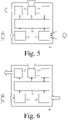
- a wireless networked lighting system is shown in a second situation.
- a detected second amount of light in the second area 2 is larger than a threshold value, and the device 10 is in this second situation configured to transmit a unicast message to the controller 20.
- the controller 20 will send a multicast message to one or more of the lamps 21-24 or will send a respective unicast message to a respective one of the one or more lamps 21-24, to switch one or more of the lamps 21-24 on.
- the lamps 21-24 are usually located at a relatively small distance from the device 10, and the controller 20 is usually located at a relatively large distance from the device 10. In case the unicast message transmitted from the device 10 to the controller 20 in the second situation gets lost or gets delayed, the one or more lamps 21-24 are not switched on or are switched on too late.
- the switching on of the one or more lamps 21-24 present in / near the first area 1 is relatively important to a person entering the first area 1, and the multicast message is to be transmitted, to increase a probability that the lamps 21-24 are informed well.
- the switching on of the one or more lamps 21-24 present in / near the first area 1 is relatively unimportant to a person entering the first area 1, and the unicast message can be transmitted.
- the first and second areas 1, 2 may be relatively coinciding areas, without having excluded other situations.
- the second area 2 may for example be smaller than the first area 1, and for example comprise one or more specific locations within the first area 1, specifically chosen for detecting amounts of light, such as centers of rooms etc.
- the first area 1 may alternatively be smaller than the second area 2, and for example comprise one or more specific locations within the second area 2, specifically chosen for detecting presences of persons, such as small areas near doors in rooms etc.
- More than one device 10 per area 1, 3, 4, 5 may be present.
- the device 10 such as for example an occupancy sensor, comprises a target detector 11 (for example a person detector) configured to detect a presence of a target (e.g. a person) in a first area 1 shown in the Fig. 1 and 2 .
- the device 10 further comprises a transmitter 12 configured to transmit a multicast message to the controller 20 and to one or more of the lamps 21-24 all shown in the Fig. 1 and 2 in response to a detection of the presence of the target in the first area 1.
- a processor 16 is coupled to the target detector 10 for receiving target detection information from the target detector 11 and to the transmitter 12 for providing the transmitter 12 with transmission information.
- the target may be an animal like a human being in this embodiment, or a domestic animal.
- the target may also be an object, for example a car.
- the target may be unidentified, i.e. any human being.
- the target detector 11 is adapted to recognize/identify a specific target, for example a specific individual and to cause the device to transmit the multicast message only if the specific individual has been recognized.
- the device 10 further comprises an internal light detector 13 that is configured to detect an amount of light in the second area 2 shown in the Fig. 1 and 2 .
- the transmitter 12 is configured to transmit the multicast message to the controller 20 and to the one or more of the lamps 21-24 for a detected relatively small first amount of light in the second area 2, and the transmitter 12 is configured to transmit a unicast message to the controller 20 in response to the detection of the presence of the target in the first area 1 for a detected relatively large second amount of light in the second area 2.
- the processor 16 is coupled to the internal light detector 13 for receiving light detection information from the internal light detector 13.
- the device 10 further comprises a calculator 15 configured to calculate a lamp-setting for a detected amount of light in the second area 2.
- the processor 16 is coupled to the calculator 15 for providing the calculator 15 with (a processed version of) the light detection information and for receiving calculation information from the calculator 15.
- the calculator 15 may form part of the processor 16, or the processor 16 may form part of the calculator 15, with a bus or connections being present between the detectors 11 and 13 and the transmitter 12 and the calculator 15.
- the calculator may use the (processed version of) the light detection information and may further possibly use controller information received from the controller 20 in whatever way.
- a second embodiment of a device is shown. This second embodiment only differs from the first embodiment in that the internal light detector 13 has been replaced by a receiver 14 configured to receive light detection information from an external light detector configured to detect the amount of light in the second area 2. All possibilities discussed for the Fig. 3 are also valid for the Fig. 4 .
- the receiver 14 may further be used to receive the controller information from the controller 20.
- the multicast message is configured to switch on at least one lamp of the one or more lamps 21-24.
- the switching on of a lamp may comprise an increase of a light intensity of the lamp from a zero level to a non-zero level.
- the multicast message may comprise a device-identification, one or more lamp-identifications, a controller-identification and a detection-result, and may further comprise (a definition of) the first area 1, (a definition of) the second area 2, and (a definition of) the non-zero level.
- a third embodiment of a device is shown.
- This third embodiment of the device 10 such as for example a lamp, only differs from the first embodiment in that a light source 17 has been added.
- This light source 17 is coupled to the processor 16 or, in case the processor forms part of the calculator 15, to the bus or the connections discussed before, or to the calculator 15 comprising the processor.
- a fourth embodiment of a device is shown.
- This fourth embodiment of the device 10 such as for example a lamp, only differs from the second embodiment in that a light source 17 has been added.
- This light source 17 is coupled to the processor 16 or, in case the processor forms part of the calculator 15, to the bus or the connections discussed before, or to the calculator 15 comprising the processor.
- the light source 17 may be configured to stay at a minimum dimming level after being switched on or may be configured to be not switched off.
- the controller 20 may inform the device 10 of this daylight mode through a unicast message or through a multicast message, or another lamp 21-24 may inform the device 10 of this daylight mode, or the internal light detector 13 may detect this daylight mode and inform the device 10, or an external light detector may inform the device 10 of this daylight mode.
- each one of the lamps 21-24 may be identical to the device 10 when comprising the light source 17, or not.
- a device is configured to form part of a wireless networked lighting system in case the device can transmit a message to another part of the wireless networked lighting system and/or in case the device can receive a message from another part of the wireless networked lighting system.
- a wireless networked lighting system comprises a controller and lamps, wherein the controller is configured to control the lamps.
- the wireless networked lighting system may further comprise a device with a presence detector (such a device is here named an occupancy sensor), or one or more of the lamps may comprise such a presence detector.
- a presence detector can detect a presence of a person directly for example through heat radiated by the person or through a movement made by the person etc.
- a presence detector can also detect a presence of a person indirectly for example through a movement of an object moved by the person or through an operation performed by the person or through a detection of an apparatus carried by the person etc.
- devices 10 comprise target detectors 11, for example person detectors for detecting presences of targets in first areas 1 and transmitters 12 for in response to detected presences transmitting multicast messages to controllers 20 and lamps 21-24 in wireless networked lighting systems.
- multicast messages increase reliabilities of the systems.
- the multicast messages switch on the lamps 21-24.
- the multicast messages are only transmitted in case relatively small amounts of light are detected in second areas 2.
- unicast messages are in response to detected presences transmitted from the devices 10 to the controllers 20 that in response control the lamps 21-24 to be switched on.
- the first and second areas 1, 2 may be at least partly overlapping areas.
- the devices 10 may comprise internal light detectors 13 for detecting the amounts of light in the second areas 2 or receivers for receiving light detection information from external light detectors.
Landscapes
- Engineering & Computer Science (AREA)
- Computer Networks & Wireless Communication (AREA)
- Circuit Arrangement For Electric Light Sources In General (AREA)
- Mobile Radio Communication Systems (AREA)
Applications Claiming Priority (2)
| Application Number | Priority Date | Filing Date | Title |
|---|---|---|---|
| EP15175447 | 2015-07-06 | ||
| PCT/EP2016/064576 WO2017005499A1 (en) | 2015-07-06 | 2016-06-23 | Occupancy messaging in wireless networked lighting system |
Publications (2)
| Publication Number | Publication Date |
|---|---|
| EP3320756A1 EP3320756A1 (en) | 2018-05-16 |
| EP3320756B1 true EP3320756B1 (en) | 2022-12-21 |
Family
ID=53682499
Family Applications (1)
| Application Number | Title | Priority Date | Filing Date |
|---|---|---|---|
| EP16731178.6A Active EP3320756B1 (en) | 2015-07-06 | 2016-06-23 | Occupancy messaging in wireless networked lighting system |
Country Status (6)
| Country | Link |
|---|---|
| US (1) | US10440804B2 (enExample) |
| EP (1) | EP3320756B1 (enExample) |
| JP (1) | JP7085842B2 (enExample) |
| CN (1) | CN107852801B (enExample) |
| RU (1) | RU2719502C2 (enExample) |
| WO (1) | WO2017005499A1 (enExample) |
Families Citing this family (6)
| Publication number | Priority date | Publication date | Assignee | Title |
|---|---|---|---|---|
| EP3482534B1 (en) * | 2016-07-05 | 2022-11-23 | Lutron Technology Company LLC | Controlling groups of electrical loads via multicast and/or unicast messages |
| US10382284B1 (en) * | 2018-03-02 | 2019-08-13 | SILVAIR Sp. z o.o. | System and method for commissioning mesh network-capable devices within a building automation and control system |
| US10769909B1 (en) * | 2018-07-02 | 2020-09-08 | Amazon Technologies, Inc. | Using sensor data to detect events |
| CN109195284B (zh) * | 2018-09-21 | 2020-07-31 | 赛尔富电子有限公司 | 照明控制方法及系统 |
| CN114189967A (zh) * | 2021-12-03 | 2022-03-15 | 中国船舶工业集团公司第七0八研究所 | 一种浮式生产装卸油装置智能照明系统 |
| AT526331B1 (de) | 2022-11-04 | 2024-02-15 | Molto Luce Gmbh | Leuchte zum Ausleuchten wenigstens zweier Raumbereiche mit einem auf einen ersten Raumbereich ausgerichteten ersten Leuchtsegment |
Family Cites Families (25)
| Publication number | Priority date | Publication date | Assignee | Title |
|---|---|---|---|---|
| US6340864B1 (en) | 1999-08-10 | 2002-01-22 | Philips Electronics North America Corporation | Lighting control system including a wireless remote sensor |
| US6912429B1 (en) | 2000-10-19 | 2005-06-28 | Destiny Networks, Inc. | Home automation system and method |
| US20040056771A1 (en) | 2001-05-14 | 2004-03-25 | Gastronics' Inc. | Apparatus and method for wireless gas monitoring |
| US6894609B2 (en) * | 2001-07-17 | 2005-05-17 | Royal Thoughts, Llc | Electrical power control and sensor module for a wireless system |
| US7889051B1 (en) * | 2003-09-05 | 2011-02-15 | The Watt Stopper Inc | Location-based addressing lighting and environmental control system, device and method |
| US7369060B2 (en) | 2004-12-14 | 2008-05-06 | Lutron Electronics Co., Inc. | Distributed intelligence ballast system and extended lighting control protocol |
| US7608807B2 (en) | 2005-05-05 | 2009-10-27 | Leviton Manufacturing Co., Inc. | Closed loop daylight harvesting light control system having auto-calibration |
| KR101502073B1 (ko) * | 2006-12-20 | 2015-03-12 | 코닌클리케 필립스 엔.브이. | 무선 네트워크, 특히 무선 조명 장치들의 네트워크의 장치들을 선택하기 위한 방법 및 시스템 |
| US8450670B2 (en) | 2007-06-29 | 2013-05-28 | Orion Energy Systems, Inc. | Lighting fixture control systems and methods |
| US9578722B2 (en) * | 2008-12-04 | 2017-02-21 | Philips Lighting Holding B.V. | Methods for selecting and controlling devices |
| WO2010092532A1 (en) * | 2009-02-13 | 2010-08-19 | Koninklijke Philips Electronics N.V. | Method for communicating in a network comprising a batteryless zigbee device, network and device therefor |
| US8410706B2 (en) | 2009-03-27 | 2013-04-02 | Lutron Electronics Co., Inc. | Method of calibrating a daylight sensor |
| US8648550B2 (en) | 2010-03-13 | 2014-02-11 | Zilog, Inc. | Ambient light sensor auto-calibration in a lighting control system |
| CN102014550A (zh) * | 2010-09-16 | 2011-04-13 | 徐大江 | 智能路灯并行控制系统及其并行控制方法 |
| US9521731B2 (en) * | 2010-12-22 | 2016-12-13 | Philips Lighting Holding B.V. | Control of network lighting systems |
| US8547036B2 (en) * | 2011-11-20 | 2013-10-01 | Available For Licensing | Solid state light system with broadband optical communication capability |
| JP5891450B2 (ja) | 2011-12-19 | 2016-03-23 | パナソニックIpマネジメント株式会社 | 照明制御システム |
| CA2762869C (en) | 2011-12-20 | 2021-09-14 | Premier Lighting Ltd. | Wireless lighting and electrical device control system |
| US10462877B2 (en) | 2012-08-06 | 2019-10-29 | Signify Holding B.V. | Out-of-the-box commissioning of a lighting control system |
| US9210759B2 (en) | 2012-11-19 | 2015-12-08 | Express Imaging Systems, Llc | Luminaire with ambient sensing and autonomous control capabilities |
| US8912735B2 (en) | 2012-12-18 | 2014-12-16 | Cree, Inc. | Commissioning for a lighting network |
| US9462663B2 (en) | 2013-05-28 | 2016-10-04 | Abl Ip Holding Llc | Interactive user interface functionality for lighting devices or system |
| US10568179B2 (en) * | 2013-09-20 | 2020-02-18 | Osram Sylvania Inc. | Techniques and photographical user interface for controlling solid-state luminaire with electronically adjustable light beam distribution |
| EP2887771B1 (en) | 2013-12-20 | 2018-02-28 | ams AG | Sensor arrangement for controlling room lighting, sensor network for controlling room lighting and method for controlling room lighting |
| WO2015157717A2 (en) * | 2014-04-11 | 2015-10-15 | Lutron Electronics Co., Inc. | Digital messages in a load control system |
-
2016
- 2016-06-23 RU RU2018104257A patent/RU2719502C2/ru active
- 2016-06-23 EP EP16731178.6A patent/EP3320756B1/en active Active
- 2016-06-23 WO PCT/EP2016/064576 patent/WO2017005499A1/en not_active Ceased
- 2016-06-23 US US15/741,273 patent/US10440804B2/en active Active
- 2016-06-23 JP JP2017564805A patent/JP7085842B2/ja not_active Expired - Fee Related
- 2016-06-23 CN CN201680039953.6A patent/CN107852801B/zh not_active Expired - Fee Related
Also Published As
| Publication number | Publication date |
|---|---|
| RU2018104257A (ru) | 2019-08-06 |
| JP2018519631A (ja) | 2018-07-19 |
| US20180199415A1 (en) | 2018-07-12 |
| EP3320756A1 (en) | 2018-05-16 |
| CN107852801B (zh) | 2020-01-24 |
| RU2018104257A3 (enExample) | 2020-02-06 |
| JP7085842B2 (ja) | 2022-06-17 |
| RU2719502C2 (ru) | 2020-04-20 |
| US10440804B2 (en) | 2019-10-08 |
| WO2017005499A1 (en) | 2017-01-12 |
| CN107852801A (zh) | 2018-03-27 |
Similar Documents
| Publication | Publication Date | Title |
|---|---|---|
| EP3320756B1 (en) | Occupancy messaging in wireless networked lighting system | |
| US8816851B2 (en) | Distributed lighting control of an area | |
| US10412814B2 (en) | Occupancy and non-occupancy detection in the lighting system | |
| US8729808B2 (en) | Commissioning coded light sources | |
| KR20110129906A (ko) | 조명 제어 네트워크 | |
| US10742510B2 (en) | Method and device for commissioning of nodes of a network | |
| JP6223428B2 (ja) | 屋外照明ネットワークにおいて照明を交通情報に基づいて適応的に制御する方法 | |
| JP2018507522A (ja) | 調光を介した存在リクエスト | |
| US20130332114A1 (en) | Systems and Methods for Commissioning a Sensor | |
| US10375802B2 (en) | Building equipment-based communication system | |
| WO2017093559A1 (en) | Intelligent lighting and sensing system and method thereof | |
| EP4055806A1 (en) | Trigger-based commissioning system | |
| EP4203624A1 (en) | Lighting control | |
| CN119766718A (zh) | 通信控制方法、装置及系统、电子设备及存储介质 | |
| KR20110019889A (ko) | 발신기 위치표시등 겸용 무선 화재신호 수신장치 | |
| BE1024372A1 (nl) | Werkwijze en systeem voor het draadloos en locatie-gebaseerd aansturen van een verlichtingsysteem |
Legal Events
| Date | Code | Title | Description |
|---|---|---|---|
| STAA | Information on the status of an ep patent application or granted ep patent |
Free format text: STATUS: THE INTERNATIONAL PUBLICATION HAS BEEN MADE |
|
| PUAI | Public reference made under article 153(3) epc to a published international application that has entered the european phase |
Free format text: ORIGINAL CODE: 0009012 |
|
| STAA | Information on the status of an ep patent application or granted ep patent |
Free format text: STATUS: REQUEST FOR EXAMINATION WAS MADE |
|
| 17P | Request for examination filed |
Effective date: 20180206 |
|
| AK | Designated contracting states |
Kind code of ref document: A1 Designated state(s): AL AT BE BG CH CY CZ DE DK EE ES FI FR GB GR HR HU IE IS IT LI LT LU LV MC MK MT NL NO PL PT RO RS SE SI SK SM TR |
|
| AX | Request for extension of the european patent |
Extension state: BA ME |
|
| DAV | Request for validation of the european patent (deleted) | ||
| DAX | Request for extension of the european patent (deleted) | ||
| RAP1 | Party data changed (applicant data changed or rights of an application transferred) |
Owner name: PHILIPS LIGHTING HOLDING B.V. |
|
| RAP1 | Party data changed (applicant data changed or rights of an application transferred) |
Owner name: SIGNIFY HOLDING B.V. |
|
| STAA | Information on the status of an ep patent application or granted ep patent |
Free format text: STATUS: EXAMINATION IS IN PROGRESS |
|
| 17Q | First examination report despatched |
Effective date: 20201105 |
|
| REG | Reference to a national code |
Ref country code: DE Ref legal event code: R079 Ref document number: 602016076998 Country of ref document: DE Free format text: PREVIOUS MAIN CLASS: H05B0037020000 Ipc: H05B0047190000 |
|
| GRAP | Despatch of communication of intention to grant a patent |
Free format text: ORIGINAL CODE: EPIDOSNIGR1 |
|
| RIC1 | Information provided on ipc code assigned before grant |
Ipc: H05B 47/115 20200101ALI20220607BHEP Ipc: H05B 47/11 20200101ALI20220607BHEP Ipc: H05B 47/19 20200101AFI20220607BHEP |
|
| STAA | Information on the status of an ep patent application or granted ep patent |
Free format text: STATUS: GRANT OF PATENT IS INTENDED |
|
| INTG | Intention to grant announced |
Effective date: 20220714 |
|
| GRAS | Grant fee paid |
Free format text: ORIGINAL CODE: EPIDOSNIGR3 |
|
| GRAA | (expected) grant |
Free format text: ORIGINAL CODE: 0009210 |
|
| STAA | Information on the status of an ep patent application or granted ep patent |
Free format text: STATUS: THE PATENT HAS BEEN GRANTED |
|
| AK | Designated contracting states |
Kind code of ref document: B1 Designated state(s): AL AT BE BG CH CY CZ DE DK EE ES FI FR GB GR HR HU IE IS IT LI LT LU LV MC MK MT NL NO PL PT RO RS SE SI SK SM TR |
|
| REG | Reference to a national code |
Ref country code: GB Ref legal event code: FG4D |
|
| REG | Reference to a national code |
Ref country code: DE Ref legal event code: R096 Ref document number: 602016076998 Country of ref document: DE |
|
| REG | Reference to a national code |
Ref country code: CH Ref legal event code: EP |
|
| REG | Reference to a national code |
Ref country code: AT Ref legal event code: REF Ref document number: 1539840 Country of ref document: AT Kind code of ref document: T Effective date: 20230115 |
|
| REG | Reference to a national code |
Ref country code: IE Ref legal event code: FG4D |
|
| REG | Reference to a national code |
Ref country code: LT Ref legal event code: MG9D |
|
| REG | Reference to a national code |
Ref country code: NL Ref legal event code: MP Effective date: 20221221 |
|
| PG25 | Lapsed in a contracting state [announced via postgrant information from national office to epo] |
Ref country code: SE Free format text: LAPSE BECAUSE OF FAILURE TO SUBMIT A TRANSLATION OF THE DESCRIPTION OR TO PAY THE FEE WITHIN THE PRESCRIBED TIME-LIMIT Effective date: 20221221 Ref country code: NO Free format text: LAPSE BECAUSE OF FAILURE TO SUBMIT A TRANSLATION OF THE DESCRIPTION OR TO PAY THE FEE WITHIN THE PRESCRIBED TIME-LIMIT Effective date: 20230321 Ref country code: LT Free format text: LAPSE BECAUSE OF FAILURE TO SUBMIT A TRANSLATION OF THE DESCRIPTION OR TO PAY THE FEE WITHIN THE PRESCRIBED TIME-LIMIT Effective date: 20221221 Ref country code: FI Free format text: LAPSE BECAUSE OF FAILURE TO SUBMIT A TRANSLATION OF THE DESCRIPTION OR TO PAY THE FEE WITHIN THE PRESCRIBED TIME-LIMIT Effective date: 20221221 |
|
| REG | Reference to a national code |
Ref country code: AT Ref legal event code: MK05 Ref document number: 1539840 Country of ref document: AT Kind code of ref document: T Effective date: 20221221 |
|
| PG25 | Lapsed in a contracting state [announced via postgrant information from national office to epo] |
Ref country code: RS Free format text: LAPSE BECAUSE OF FAILURE TO SUBMIT A TRANSLATION OF THE DESCRIPTION OR TO PAY THE FEE WITHIN THE PRESCRIBED TIME-LIMIT Effective date: 20221221 Ref country code: LV Free format text: LAPSE BECAUSE OF FAILURE TO SUBMIT A TRANSLATION OF THE DESCRIPTION OR TO PAY THE FEE WITHIN THE PRESCRIBED TIME-LIMIT Effective date: 20221221 Ref country code: HR Free format text: LAPSE BECAUSE OF FAILURE TO SUBMIT A TRANSLATION OF THE DESCRIPTION OR TO PAY THE FEE WITHIN THE PRESCRIBED TIME-LIMIT Effective date: 20221221 Ref country code: GR Free format text: LAPSE BECAUSE OF FAILURE TO SUBMIT A TRANSLATION OF THE DESCRIPTION OR TO PAY THE FEE WITHIN THE PRESCRIBED TIME-LIMIT Effective date: 20230322 |
|
| P01 | Opt-out of the competence of the unified patent court (upc) registered |
Effective date: 20230425 |
|
| PG25 | Lapsed in a contracting state [announced via postgrant information from national office to epo] |
Ref country code: NL Free format text: LAPSE BECAUSE OF FAILURE TO SUBMIT A TRANSLATION OF THE DESCRIPTION OR TO PAY THE FEE WITHIN THE PRESCRIBED TIME-LIMIT Effective date: 20221221 |
|
| PG25 | Lapsed in a contracting state [announced via postgrant information from national office to epo] |
Ref country code: SM Free format text: LAPSE BECAUSE OF FAILURE TO SUBMIT A TRANSLATION OF THE DESCRIPTION OR TO PAY THE FEE WITHIN THE PRESCRIBED TIME-LIMIT Effective date: 20221221 Ref country code: RO Free format text: LAPSE BECAUSE OF FAILURE TO SUBMIT A TRANSLATION OF THE DESCRIPTION OR TO PAY THE FEE WITHIN THE PRESCRIBED TIME-LIMIT Effective date: 20221221 Ref country code: PT Free format text: LAPSE BECAUSE OF FAILURE TO SUBMIT A TRANSLATION OF THE DESCRIPTION OR TO PAY THE FEE WITHIN THE PRESCRIBED TIME-LIMIT Effective date: 20230421 Ref country code: ES Free format text: LAPSE BECAUSE OF FAILURE TO SUBMIT A TRANSLATION OF THE DESCRIPTION OR TO PAY THE FEE WITHIN THE PRESCRIBED TIME-LIMIT Effective date: 20221221 Ref country code: EE Free format text: LAPSE BECAUSE OF FAILURE TO SUBMIT A TRANSLATION OF THE DESCRIPTION OR TO PAY THE FEE WITHIN THE PRESCRIBED TIME-LIMIT Effective date: 20221221 Ref country code: CZ Free format text: LAPSE BECAUSE OF FAILURE TO SUBMIT A TRANSLATION OF THE DESCRIPTION OR TO PAY THE FEE WITHIN THE PRESCRIBED TIME-LIMIT Effective date: 20221221 Ref country code: AT Free format text: LAPSE BECAUSE OF FAILURE TO SUBMIT A TRANSLATION OF THE DESCRIPTION OR TO PAY THE FEE WITHIN THE PRESCRIBED TIME-LIMIT Effective date: 20221221 |
|
| PGFP | Annual fee paid to national office [announced via postgrant information from national office to epo] |
Ref country code: FR Payment date: 20230622 Year of fee payment: 8 |
|
| PG25 | Lapsed in a contracting state [announced via postgrant information from national office to epo] |
Ref country code: SK Free format text: LAPSE BECAUSE OF FAILURE TO SUBMIT A TRANSLATION OF THE DESCRIPTION OR TO PAY THE FEE WITHIN THE PRESCRIBED TIME-LIMIT Effective date: 20221221 Ref country code: PL Free format text: LAPSE BECAUSE OF FAILURE TO SUBMIT A TRANSLATION OF THE DESCRIPTION OR TO PAY THE FEE WITHIN THE PRESCRIBED TIME-LIMIT Effective date: 20221221 Ref country code: IS Free format text: LAPSE BECAUSE OF FAILURE TO SUBMIT A TRANSLATION OF THE DESCRIPTION OR TO PAY THE FEE WITHIN THE PRESCRIBED TIME-LIMIT Effective date: 20230421 Ref country code: AL Free format text: LAPSE BECAUSE OF FAILURE TO SUBMIT A TRANSLATION OF THE DESCRIPTION OR TO PAY THE FEE WITHIN THE PRESCRIBED TIME-LIMIT Effective date: 20221221 |
|
| REG | Reference to a national code |
Ref country code: DE Ref legal event code: R097 Ref document number: 602016076998 Country of ref document: DE |
|
| PLBE | No opposition filed within time limit |
Free format text: ORIGINAL CODE: 0009261 |
|
| STAA | Information on the status of an ep patent application or granted ep patent |
Free format text: STATUS: NO OPPOSITION FILED WITHIN TIME LIMIT |
|
| PG25 | Lapsed in a contracting state [announced via postgrant information from national office to epo] |
Ref country code: DK Free format text: LAPSE BECAUSE OF FAILURE TO SUBMIT A TRANSLATION OF THE DESCRIPTION OR TO PAY THE FEE WITHIN THE PRESCRIBED TIME-LIMIT Effective date: 20221221 |
|
| PGFP | Annual fee paid to national office [announced via postgrant information from national office to epo] |
Ref country code: GB Payment date: 20230620 Year of fee payment: 8 |
|
| 26N | No opposition filed |
Effective date: 20230922 |
|
| PGFP | Annual fee paid to national office [announced via postgrant information from national office to epo] |
Ref country code: DE Payment date: 20230828 Year of fee payment: 8 |
|
| PG25 | Lapsed in a contracting state [announced via postgrant information from national office to epo] |
Ref country code: MC Free format text: LAPSE BECAUSE OF FAILURE TO SUBMIT A TRANSLATION OF THE DESCRIPTION OR TO PAY THE FEE WITHIN THE PRESCRIBED TIME-LIMIT Effective date: 20221221 |
|
| PG25 | Lapsed in a contracting state [announced via postgrant information from national office to epo] |
Ref country code: SI Free format text: LAPSE BECAUSE OF FAILURE TO SUBMIT A TRANSLATION OF THE DESCRIPTION OR TO PAY THE FEE WITHIN THE PRESCRIBED TIME-LIMIT Effective date: 20221221 Ref country code: MC Free format text: LAPSE BECAUSE OF FAILURE TO SUBMIT A TRANSLATION OF THE DESCRIPTION OR TO PAY THE FEE WITHIN THE PRESCRIBED TIME-LIMIT Effective date: 20221221 |
|
| REG | Reference to a national code |
Ref country code: CH Ref legal event code: PL |
|
| REG | Reference to a national code |
Ref country code: BE Ref legal event code: MM Effective date: 20230630 |
|
| PG25 | Lapsed in a contracting state [announced via postgrant information from national office to epo] |
Ref country code: LU Free format text: LAPSE BECAUSE OF NON-PAYMENT OF DUE FEES Effective date: 20230623 |
|
| REG | Reference to a national code |
Ref country code: IE Ref legal event code: MM4A |
|
| PG25 | Lapsed in a contracting state [announced via postgrant information from national office to epo] |
Ref country code: LU Free format text: LAPSE BECAUSE OF NON-PAYMENT OF DUE FEES Effective date: 20230623 |
|
| PG25 | Lapsed in a contracting state [announced via postgrant information from national office to epo] |
Ref country code: IE Free format text: LAPSE BECAUSE OF NON-PAYMENT OF DUE FEES Effective date: 20230623 |
|
| PG25 | Lapsed in a contracting state [announced via postgrant information from national office to epo] |
Ref country code: IE Free format text: LAPSE BECAUSE OF NON-PAYMENT OF DUE FEES Effective date: 20230623 Ref country code: CH Free format text: LAPSE BECAUSE OF NON-PAYMENT OF DUE FEES Effective date: 20230630 |
|
| PG25 | Lapsed in a contracting state [announced via postgrant information from national office to epo] |
Ref country code: IT Free format text: LAPSE BECAUSE OF FAILURE TO SUBMIT A TRANSLATION OF THE DESCRIPTION OR TO PAY THE FEE WITHIN THE PRESCRIBED TIME-LIMIT Effective date: 20221221 Ref country code: BE Free format text: LAPSE BECAUSE OF NON-PAYMENT OF DUE FEES Effective date: 20230630 |
|
| PG25 | Lapsed in a contracting state [announced via postgrant information from national office to epo] |
Ref country code: BG Free format text: LAPSE BECAUSE OF FAILURE TO SUBMIT A TRANSLATION OF THE DESCRIPTION OR TO PAY THE FEE WITHIN THE PRESCRIBED TIME-LIMIT Effective date: 20221221 |
|
| PG25 | Lapsed in a contracting state [announced via postgrant information from national office to epo] |
Ref country code: BG Free format text: LAPSE BECAUSE OF FAILURE TO SUBMIT A TRANSLATION OF THE DESCRIPTION OR TO PAY THE FEE WITHIN THE PRESCRIBED TIME-LIMIT Effective date: 20221221 |
|
| REG | Reference to a national code |
Ref country code: DE Ref legal event code: R119 Ref document number: 602016076998 Country of ref document: DE |
|
| GBPC | Gb: european patent ceased through non-payment of renewal fee |
Effective date: 20240623 |
|
| PG25 | Lapsed in a contracting state [announced via postgrant information from national office to epo] |
Ref country code: DE Free format text: LAPSE BECAUSE OF NON-PAYMENT OF DUE FEES Effective date: 20250101 |
|
| PG25 | Lapsed in a contracting state [announced via postgrant information from national office to epo] |
Ref country code: FR Free format text: LAPSE BECAUSE OF NON-PAYMENT OF DUE FEES Effective date: 20240630 |
|
| PG25 | Lapsed in a contracting state [announced via postgrant information from national office to epo] |
Ref country code: GB Free format text: LAPSE BECAUSE OF NON-PAYMENT OF DUE FEES Effective date: 20240623 |
|
| PG25 | Lapsed in a contracting state [announced via postgrant information from national office to epo] |
Ref country code: CY Free format text: LAPSE BECAUSE OF FAILURE TO SUBMIT A TRANSLATION OF THE DESCRIPTION OR TO PAY THE FEE WITHIN THE PRESCRIBED TIME-LIMIT; INVALID AB INITIO Effective date: 20160623 |
|
| PG25 | Lapsed in a contracting state [announced via postgrant information from national office to epo] |
Ref country code: HU Free format text: LAPSE BECAUSE OF FAILURE TO SUBMIT A TRANSLATION OF THE DESCRIPTION OR TO PAY THE FEE WITHIN THE PRESCRIBED TIME-LIMIT; INVALID AB INITIO Effective date: 20160623 |
|
| PG25 | Lapsed in a contracting state [announced via postgrant information from national office to epo] |
Ref country code: TR Free format text: LAPSE BECAUSE OF FAILURE TO SUBMIT A TRANSLATION OF THE DESCRIPTION OR TO PAY THE FEE WITHIN THE PRESCRIBED TIME-LIMIT Effective date: 20221221 |