EP3320738B1 - Auf burst basierende übertragungsplanung in einem drahtloskommunikationssystem - Google Patents
Auf burst basierende übertragungsplanung in einem drahtloskommunikationssystem Download PDFInfo
- Publication number
- EP3320738B1 EP3320738B1 EP15901204.6A EP15901204A EP3320738B1 EP 3320738 B1 EP3320738 B1 EP 3320738B1 EP 15901204 A EP15901204 A EP 15901204A EP 3320738 B1 EP3320738 B1 EP 3320738B1
- Authority
- EP
- European Patent Office
- Prior art keywords
- subframes
- grant message
- consecutive
- laa
- uplink subframes
- Prior art date
- Legal status (The legal status is an assumption and is not a legal conclusion. Google has not performed a legal analysis and makes no representation as to the accuracy of the status listed.)
- Active
Links
- 230000005540 biological transmission Effects 0.000 title claims description 47
- 238000004891 communication Methods 0.000 title description 16
- 238000000034 method Methods 0.000 claims description 53
- 238000010586 diagram Methods 0.000 description 31
- 230000006870 function Effects 0.000 description 9
- 238000012545 processing Methods 0.000 description 9
- 238000001228 spectrum Methods 0.000 description 6
- 230000001360 synchronised effect Effects 0.000 description 5
- 239000000969 carrier Substances 0.000 description 4
- 238000013461 design Methods 0.000 description 3
- 230000007246 mechanism Effects 0.000 description 3
- 230000003287 optical effect Effects 0.000 description 3
- 238000003491 array Methods 0.000 description 2
- 230000000903 blocking effect Effects 0.000 description 2
- 208000028626 extracranial carotid artery aneurysm Diseases 0.000 description 2
- 239000000463 material Substances 0.000 description 2
- 239000004065 semiconductor Substances 0.000 description 2
- 230000011664 signaling Effects 0.000 description 2
- 230000000007 visual effect Effects 0.000 description 2
- 208000002193 Pain Diseases 0.000 description 1
- 230000033228 biological regulation Effects 0.000 description 1
- 230000007423 decrease Effects 0.000 description 1
- 230000001419 dependent effect Effects 0.000 description 1
- 238000001514 detection method Methods 0.000 description 1
- 230000000694 effects Effects 0.000 description 1
- 238000005516 engineering process Methods 0.000 description 1
- 230000010354 integration Effects 0.000 description 1
- 230000007774 longterm Effects 0.000 description 1
- 238000004519 manufacturing process Methods 0.000 description 1
- 238000012544 monitoring process Methods 0.000 description 1
- 229920001690 polydopamine Polymers 0.000 description 1
- 230000001105 regulatory effect Effects 0.000 description 1
- 230000002441 reversible effect Effects 0.000 description 1
- 239000004984 smart glass Substances 0.000 description 1
- 230000003068 static effect Effects 0.000 description 1
Images


Classifications
-
- H—ELECTRICITY
- H04—ELECTRIC COMMUNICATION TECHNIQUE
- H04L—TRANSMISSION OF DIGITAL INFORMATION, e.g. TELEGRAPHIC COMMUNICATION
- H04L5/00—Arrangements affording multiple use of the transmission path
- H04L5/0001—Arrangements for dividing the transmission path
- H04L5/0003—Two-dimensional division
- H04L5/0005—Time-frequency
- H04L5/0007—Time-frequency the frequencies being orthogonal, e.g. OFDM(A), DMT
- H04L5/001—Time-frequency the frequencies being orthogonal, e.g. OFDM(A), DMT the frequencies being arranged in component carriers
-
- H—ELECTRICITY
- H04—ELECTRIC COMMUNICATION TECHNIQUE
- H04L—TRANSMISSION OF DIGITAL INFORMATION, e.g. TELEGRAPHIC COMMUNICATION
- H04L5/00—Arrangements affording multiple use of the transmission path
- H04L5/003—Arrangements for allocating sub-channels of the transmission path
- H04L5/0053—Allocation of signaling, i.e. of overhead other than pilot signals
-
- H—ELECTRICITY
- H04—ELECTRIC COMMUNICATION TECHNIQUE
- H04L—TRANSMISSION OF DIGITAL INFORMATION, e.g. TELEGRAPHIC COMMUNICATION
- H04L5/00—Arrangements affording multiple use of the transmission path
- H04L5/0091—Signaling for the administration of the divided path
- H04L5/0094—Indication of how sub-channels of the path are allocated
-
- H—ELECTRICITY
- H04—ELECTRIC COMMUNICATION TECHNIQUE
- H04W—WIRELESS COMMUNICATION NETWORKS
- H04W72/00—Local resource management
- H04W72/20—Control channels or signalling for resource management
- H04W72/23—Control channels or signalling for resource management in the downlink direction of a wireless link, i.e. towards a terminal
-
- H—ELECTRICITY
- H04—ELECTRIC COMMUNICATION TECHNIQUE
- H04W—WIRELESS COMMUNICATION NETWORKS
- H04W16/00—Network planning, e.g. coverage or traffic planning tools; Network deployment, e.g. resource partitioning or cells structures
- H04W16/14—Spectrum sharing arrangements between different networks
Definitions
- the subject matter disclosed herein relates generally to wireless communications and more particularly relates to burst-based transmission scheduling in a wireless communication system.
- a base unit a method performed by a base unit, a remote unit, and a method performed by a remote unit.
- LAA may facilitate a fair coexistence with other technologies over the unlicensed spectrum and satisfy various regulatory requirements in different countries and regions.
- ETSI has specified two channel access mechanism (i.e., FBE and LBE).
- FBE frequency division multiple access
- the equipment i.e., FBE amd LBE
- the equipment may perform a CCA check by using energy detection with the CCA observation time not less than 20 microseconds ("us"). If the energy level in the channel does not exceed a predefined threshold corresponding to the power level, the equipment may consider the operating channel to be occupied and may continue to perform the CCA check.
- FBE the equipment may continue to perform the CCA check at an end of a frame period.
- LBE the equipment may start performing ECCA immediately until it can grab the channel. In some situations, LBE may have a higher channel access probability than FBE.
- LBE may have a higher channel access probability than FBE.
- FBE may be more appropriate for LAA UL.
- FBE can follow the LTE UL framework that a UE's UL transmission should be permitted by a serving eNB, FBE can avoid inter-UE blocking and enable UL multiplexing of the multiple UEs in one subframe by FDMA and MU-MIMO.
- FBE does not require a reservation signal, and FBE has a fixed timing relationship and UL transmission can always start from the first OFDM symbol of subframe. Accordingly, in certain configurations, FBE may be used as as baseline for LAA UL operation.
- LBT/CCA should be synchronous between UEs on the same carrier. Otherwise, the first UE would reserve the operating channel and the other UEs would see it as occupied, which would block multiplexing of multiple UEs in a UL subframe. For example, in a configuration in which a first UE (e.g, UE1) and a second UE (e.g., UE2) operate in an asynchronous manner, if UE1 performs CCA before UE2 then UE1 will transmit data immediately on the unlicensed spectrum if UE1 passes its CCA.
- a first UE e.g, UE1
- a second UE e.g., UE2
- This inter-UE blocking issue may not only block multi-user multiplexing in on subframe but also may inhibit fairly sharing the unlicensed spectrum.
- LBT/CCA may be synchronized among the UEs.
- all served UEs may be synchronous and scheduled from the first UL subframe in one frame period.
- a frame period may include an occupancy time followed by an idle period.
- LBT/CCA for all served UEs in a cell may occur at the end of the idle period.
- a UE may transmit only depending on an eNB's scheduling, thereby using the LTE UL framework. Because all the served UEs perform CCA in a synchronous manner, UL transmission can start only at the beginning of each frame period.
- cross-carrier scheduling uses a licensed carrier to schedule unlicensed secondary carriers and can avoid using the eNB to perform a CCA check before each UL grant transmission.
- self-scheduling requires the eNB to perform the CCA check before each UL grant transmission. Therefore, compared to self-scheduling, cross-carrier scheduling enables the eNB to always have the opportunity to transmit the UL grant transmission.
- On Scheduling and HARQ operation for LAA is a discussion document numbered Rl-153144 from 3GPP TSG-RAN WG1 Meeting #81 in Fukuoka, Japan on 25th to 29th May 2015 .
- Consideration on the UL scheduling design for LAA is a discussion document numbered Rl-150511 from 3GPP TSG RAN WG1 Meeting #80 in Athens, Greece on 9th to 13th February 2015 .
- UL Transmission for LAA is a discussion document numbered R2-152343 from 3GPP TSG RAN WG2 #90 in Fukuoka, Japan on 25th to 29th May 2015 .
- R1-150490 is a 3GPP discussion document titled " Frame structure design for LAA with LBT" submitted by ITL Inc. at TSG RAN WG1 Meeting #80 in Athens, Greece, on 9th February 2015 and describes some high level functional PHY design options especially for the potential LAA frame structure and the channel access mechanism.
- Claim 1 defines a base unit
- claim 6 defines a method performed by a base unit
- claim 13 defines a remote unit
- claim 14 defines a method performed by a remote unit.
- embodiments may be embodied as a system, apparatus, method, or program product. Accordingly, embodiments may take the form of an entirely hardware embodiment, an entirely software embodiment (including firmware, resident software, micro-code, etc.) or an embodiment combining software and hardware aspects that may all generally be referred to herein as a "circuit," "module” or “system.” Furthermore, embodiments may take the form of a program product embodied in one or more computer readable storage devices storing machine readable code, computer readable code, and/or program code, referred hereafter as code. The storage devices may be tangible, non-transitory, and/or non-transmission. The storage devices may not embody signals. In a certain embodiment, the storage devices only employ signals for accessing code.
- modules may be implemented as a hardware circuit comprising custom very-large-scale integration ("VLSI") circuits or gate arrays, off-the-shelf semiconductors such as logic chips, transistors, or other discrete components.
- VLSI very-large-scale integration
- a module may also be implemented in programmable hardware devices such as field programmable gate arrays, programmable array logic, programmable logic devices or the like.
- Modules may also be implemented in code and/or software for execution by various types of processors.
- An identified module of code may, for instance, include one or more physical or logical block of executable code which may, for instance, be organized as an object procedure, or function. Nevertheless, the executable of an identified module need not be physically located together, but may include disparate instructions stored in different locations which, when joined logically together, include the module and achieve the stated purpose for the module.
- a module of code may be a single instruction, or many instructions, and may even be distributed over several different code segments, among different programs, and across several memory devices.
- operational data may be identified and illustrated herein within modules, and may be embodied in any suitable form and organized within any suitable type of data structure. The operational data may be collected as a single data set, or may be distributed over different locations including over different computer readable storage devices.
- the software portions are stored on one or more computer readable storage devices.
- the computer readable medium may be a computer readable storage medium.
- the computer readable storage medium may be a storage device storing the code.
- the storage device may be, for example, but not limited to, an electronic, magnetic, optical, electromagnetic, infrared, holographic, micromechanical, or semiconductor system, apparatus, or device, or any suitable combinations of the foregoing.
- a storage device More specific examples (a non-exhaustive list) of the storage device would include the following an electrical connection having one or more wires, a portable computer diskette, a hard disk, a random access memory (“RAM”), a read-only memory (“ROM”), an erasable programmable read-only memory (“EPROM”) or Flash memory), a portable compact disc read-only memory (“CD-ROM”),an optical storage device, a magnetic storage device, or any suitable combination of the foregoing.
- a computer readable storage medium may be any tangible medium that can contain, or store a program for use by or in connection with an instruction execution system, apparatus, or device.
- Code for carrying out operations for embodiment may be any number of lines and may be written in any combination of one or more programming languages including an object oriented programming language such as Python, Ruby, Java, Smalltalk, C++, or the like, and conventional procedural programming languages, such as the "C" programming language, or the like, and/or machine languages such as assembly languages.
- the code may execute entirely on the user's computer, partly on the user's computer, as a stand-alone software package, partly on the user's computer and partly on remote computer or entirely on the remote computer or server.
- the remote computer may be connected to the user's computer through any type of network, including a local area network (“LAN”) or a wide are network (“WAN”), or the connection may be made to an external computer (for example, through the Internet using an Internet Service Provider).
- LAN local area network
- WAN wide are network
- Internet Service Provider an Internet Service Provider
- the code may also be stored in a storage device that can direct a computer, other programmable data processing apparatus, or other devices to function in a particular manner, such that the instructions stored in the storage device produce an article of manufacture including instructions which implement the function/act specified in the schematic flowchart diagrams and/or schematic block diagrams block or blocks.
- the code may also be loaded onto a computer, other programmable data processing apparatus, or other devices to cause a series of operational steps to be performed on the computer, other programmable apparatus or other devices to produce a computer implemented process such that the code which execute on the computer or other programmable apparatus provide processes for implementing the functions/acts specified in the flowchart and/or block diagram block or blocks.
- each block in the schematic flowchart diagrams and/or schematic block diagrams may represent a module, segment, or portion of code, which includes one or more executable instructions of the code for implementing the specified logical function(s).
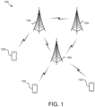
- Figure 1 depicts an embodiment of a wireless communication system 100 for burst-based transmission.
- the wireless communication system 100 includes remote units 102 and base units 104. Even though a specific number of remote units 102 and base units 104 are depicted in Figure 1 , one of skill in the art will recognize that any number of remote units 102 and base units 104 may be included in the wireless communication system 100.
- the remote units 102 may include computing devices, such as desktop computers, laptop computers, personal digital assistants ("PDAs"), tablet computers, smart phones, smart televisions (e.g., televisions connected to the Internet), set-top boxes, game consoles, security systems (including security cameras), vehicle on-board computers, network devices (e.g., routers, switches, modems), or the like.
- the remote units 102 include wearable devices, such as smarts watches, fitness bands, optical head-mounted displays, or the like.
- the remote units 102 may be referred to as subscriber units, mobiles, mobile stations, users, terminals, mobile terminals, fixed terminals, subscriber stations, UE, user terminals, or by other terminology used in the art.
- the remote units 102 may communicate directly with one or more of the base units 104 via UL communication signals.
- the base units 104 may be distributed over a geographic region.
- a base unit 104 may also be reffered to as an access point, an access terminal, a base, a base station, a Node-B, an eNB, a Home Node-B, a relay node, or by any other terminology used in the art.
- the base units 104 are generally part of a radio access network that includes one or more controllers communicably coupled to one or more corresponding base units 104.
- the radio access network is generally communicably coupled to one or more core networks, which may be coupled to other networks, like the Internet and public switched telephone networks, among other networks. These and other elements of radio access and core networks are not illustrated but are well known generally by those having ordinary skill in the art.
- the wireless communication system 100 is compliant with the LTE of the 3GPP UMTS protocol, wherein the base unit 104 transmits using an OFDM modulation scheme on the DL and the remote units 102 transmit on the UL using a SC-FDMA scheme. More generally, however, the wireless communication system 100 may implement some other open or proprietary communication protocol, for example, WiMAX, among other protocols. The present disclosure is not intended to be limited to the implementation of any particular wireless comunication system architecture or protocol.
- the base units 104 may serve a number of remote units 102 within a serving area, for example, a cell or a cell sector via a wireless comunication link.
- the base units 104 transmit DL comunication singnals to serve the remote units 102 in the time, frequency. and/or spatial domain.
- a base unit 104 may determine multiple consecutive UL subframes to be transmited from a remote unit 102.
- the base unit 104 may form an UL grant message to schedule transmission of the multiple consecutive UL subframes.
- the base unit 104 may provide the UL grant message to the remote unit 102.
- the remote unit 102 may receive the UL grant message.
- the remote unit 102 may determine a frame period to transmit the multiple consecutive UL subframes based on a portion of the UL grant message.
- the remote unit 102 may determine a number of the multiple consecutive UL subframes to transmit based on the portion of the UL grant message.
- the remote unit 102 may transmit the number of the multiple consecutive UL subframes starting at a first subframe of the frame period.
- Figure 2 depicts one embodiment of an apparatus 200 that may be used for burst-based transmission.
- the apparatus 200 includes one embodiment of the remote unit 102.
- the remote unit 102 may include a procesor 202, a memory 204, an input device 206, a display 208, a transmiter 210, and a receiver 212.
- the input device 206, and the display 208 are combined into a single device, such as a touchscreen.
- the processor 202 may include any known controller capable of executing computer-readable instructions and/or capable of performing logical operations.
- the processor 202 may be a microcontroller, a microprocessor, a central processing unit (“CPU") a graphics processing unit (“GPU”), an auxiliary processing unit, a filed programmable gate array (“FPGA”), or similar programmable controller.
- the processor 202 executes instructions stored in the memory 204 to perform the methods and mutines described herein.
- the processor 202 is communicatively coupled to the memory 204, the input device 206, the display 208, the transmitter 210, and the receive 212.
- the memory 204 in one embodiment, is a computer readable storage medium.
- the memory 204 includes volatile computer storage media.
- the memory 204 may include a RAM including dynamic RAM (“DRAM”), synchronous dynamic RAM (“SDRAM”), and/or static RAM (“SRAM”)
- the memory 204 includes non-volatile computer storage media.
- the memory 204 may include a hard disk drive, a flash memory, or any other suitable non-volatile computer storage device.
- the memory 204 includes both volatile and non-volatile computer storage media.
- the memory 204 stores data relating to frame periods.
- the memory 204 also stores program code and related data, such as an operating system or other controller algorithms operating on the remote unit 102.
- the input device 206 may include any known computer input device including a touch panel, a button, a keyboard, a stylus, a microphone, or the like.
- the input device 206 may be integrated with the display 208, for example, as a touchscreen or similar touch-sensitive display.
- the input device 206 includes a touchscreen such that text may be input using a virtual keyboard displayed on the touchscreen and/or by handwriting on the touchscreen.
- the input device 206 includes two or more different devices, such as a keyboard and a touch panel.
- the display 208 may include any known electronically controllable display or display device.
- the display 208 may be designed to output visual, audible, and/or haptic signals.
- the display 208 includes an electronic display capable of outputting visual data to a user.
- the display 208 may include, but is not limited to, an LCD display, an LED display, an OLED display, a projector, or similar display device capable of outputting images, text, or the like to a user.
- the display 208 may include a wearable display such as a smart watch, smart glasses, a heads-up display, or the like.
- the display 208 may be a component of a smart phone, a personal digital assistant, a television, a table computer, a notebook (laptop) computer, a personal computer, a vehicle dashboard, or the like.
- the display 208 includes one or more speakers for producing sound.
- the display 208 may produce an audible alert or notification (e.g., a beep or chime).
- the display 208 includes one or more haptic devices for producing vibrations, motion, or other haptic feedback.
- all or portions of the display 208 may be integrated with the input device 206.
- the input device 206 and display 208 may form a touchscreen or similar touch-sensitive display.
- the display 208 may be located near the input device 206.
- the transmitter 210 is used to provide UL communication signals to the base unit 104 and the receiver 212 is used to receive DL communication signals from the base unit 104.
- the transmitter 210 is used to transmit multiple consecutive UL subframes to the base unit 104 starting at a first subframe of a frame period.
- a number of the multiple consecutive UL subframes may be provided to the remote unit 102 by the base unit 104, and the remote unit 102 may use the transmitter 210 to transmit the number of the multiple consecutive UL subframes to the base unit 104.
- the base unit 104 may provide the number six to the remote unit, and the remote unit 102 may use the transmitter 210 to transmit six multiple consecutive UL subframes to the base unit 104.
- the receiver 212 may receive a UL grant message sent by the base unit 104. Although only one transmitter 210 and one receiver 212 are illustrated, the remote unit 102 may have any suitable number of transmitters 210 and receivers 212. The transmitter 210 and the receiver 212 may be any suitable type of transmitters and receivers. In one embodiment, the transmitter 210 and the receiver 212 may be part of a transceiver.
- Figure 3 depicts another embodiment of an apparatus 300 that may be used for burst-based transmission.
- the apparatus 300 includes one embodiment of the base unit 104.
- the base unit 104 may include a processor 302, a memory 304, an input device 306, a display 308, a transmitter 310, and a receiver 312.
- the processor 302, the memory 304, the input device 306, and the display 308 may be substantially similar to the processor 202, the memory 204, the input device 206, and the display 208 of the remote unit 102, respectively.
- the transmitter 310 is used to provide DL communication signals to the remote unit 102 and the receiver 312 is used to receive UL communication signals from the remote unit 102. In one embodiment, the transmitter 310 is used to provide a UL grant message to the remote unit 102 (e.g., UE). Although only one transmitter 310 and one receiver 312 are illustrated, the base unit 104 may have any suitable number of transmitters 310 and receivers 312. The transmitter 310 and the receiver 312 may be any suitable type of transmitters and receivers. In one embodiment, the transmitter 310 and the receiver 312 may be part of a transmitter.
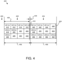
- Figure 4 depicts one embodiment of a frame configuration 400 that facilitates burst-based transmission.
- the frame configuration 400 represents data transmitted between a remote unit 102 and a base unit 104.
- the frame confirguration 400 includes a first frame 402 and a second frame 404.
- the first frame 402 has a frame period 406 of 4 ms and second frame 404 has a frame period 408 of 4 milliseconds ("ms").
- the first and second frames 402 and 404 each include four subframes, with each subframe having a period of 1 ms.
- the frame periods 406 and 408 of 4 ms are examples of possible frame periods.
- the frame period may be 1 ms, 2 ms, 3 ms, 5 ms, 6 ms, 7 ms, 8 ms, 9 ms, or 10 ms, for example.
- the frame configuration 400 may have any number of frames.
- each of the first and second frames 402 and 404 may have any suitable number of subframes, with each subframe having any suitable period.
- one or more of the first and second frames 402 and 404 may have 1, 2, 3, 5, 6, 7, 8, 9, 10, for example.
- each of the first and second frames 402 and 404 has multi-user multiplexing. As such, data from multiple UEs is multiplexed in each of the first and second frames 402 and 404. Although data from three UEs is multiplexed in each of the first and second frames 402 and 404, data from any suitable number of UEs may be multiplexed during each of the first and second frames 402 and 404.
- UL data from a first remote unit 102 (e.g., UE1UL) 410, 412, 414, and 416 is transmitted to a base unit 104 during three subframes and one partial subframe, while UL data from a second remote unit 102 (e.g., UE2UL) 418, and 420 is transmitted to the base unit 104 during two subframes.
- the subframes 422 and 424 do not include UE2 or UE3 data. In certain embodiments, subframes 422 and 424 may be used by UE1.
- UL data from a third remote unit 102 (e.g., UE3UL) 426 is transmitted to the base unit 104 during one subframe with the subframes 428, 430, and 432 not including UE3 data.
- a third remote unit 102 e.g., UE3UL
- the first frame 402 includes an idle period 434 at the end of the frame.
- the idle period 434 decreases the time available for UL data by a portion of the fourth subframe.
- the idle period 434 has an idle duration 436 that when added with a maximum channel occupancy time 438 equals the frame period 406.
- the idle duration 436 is at least 5% of the maximum channel occupancy time 438.
- UL data is only transmitted during the maximum channel occupancy time 438, therefore a maximum of three subframes and one partial subframe of UL data may be transmitted during one frame period.
- LBT/CCA occurs at the end of the idle period 434.
- UL data from the first remote unit 102 (e.g., UE1UL) 440, 442, and 444, is transmitted to the base unit 104 during three subframes, while UL data from a fourth remote unit 102 (e.g., UE4UL) 448 is transmitted to the base unit 104 during one subframes.
- the subframes 450, 452, and 454 do not include UE4 data.
- UL data from a fifth remote unit 102 e.g., UE5UL
- the second frame 404 includes an idle period 464 at the end of the frame.
- Burst-based transmission from the base unit 104 may be used for a LAA UL GRANT message 466 in order to save signaling overhead of the licensed carrier when cross-scheduling from a licensed carrier to schedule unlicensed secondary carriers. Specifically, the burst is scheduled for LAA UL from the base unit 104 to a remote unit 102 using only one UL grant message 466 to schedule multiple consecutive UL subframes.
- the UL grant message 466 is transmitted at least 4 ms before the starting frame of a corresponding frame period. From a single remote unit 102 perspective, the UL grant message 466 can be transmitted only once for each frame period. Accordingly, the UL grant message 466 is transmitted prior to the the first frame 402, however, the UL grant message 466 grants UL transmissions for the second frame 404 to enable 4 ms to elapse between the UL grant message 466 and the corresponding frame period.
- the UL transmissions from the remote units 102 start from the first UL subframe for each frame period (e.g. UE1UL 410, UE2UL 418, UE3UL 426, UE1UL 440, UE4UL 448, and UE5UL 456).
- the maximum duration of UL transmission is equal to the maximum channel occupancy time 438.
- Information corresponding to the burst duration is contained in ths UL grant message 466 from the base unit 104 to schedule multiple consecutive subframes for one remote unit 102 with the same frequency resource and MCS because the remote unit's 102 UL transmission is fully dependent on the base unit's 104 scheduling decision.
- a number of multiple consecutive UL subframes is contained in the UL grant message 466.
- EU European Union
- 4 bits may be used to cover a burst length front 1 ms to 10 ms (e.g. the 4 bits will cover possible numbers of 1-10 consecutive UL subframes)
- an offset for the last subframe with respect to the starting subframe in the frame period may be indicated in the UL grant message 466.
- the first subframe in the 4 ms frame period may be considered subframe 0 and the fourth subframe may be considered subframe 3, so the UL grant message 466 may indicate a binary "11" to indicate that the last subframe for the current burst transmission is subframe 3, so this is the last subframe for a UL frame period that is 4. 4.
- the remothe unit 102 may treat the last UL subframe as a partial subframe with a fixed number of OFDM symbols reserved for the idle period 464. For example, if the frame period is set to 10 ms, the maximum channel occupancy time 438 will enable 9 full subframes and one partial subframe. In such an example, the partial subframe has a length of 7 OFDM symbols, and the idle period 464 includes 7 OFDM symbols, thereby giving the idle period 464 at least 5% of the maximum channel occupancy time 438,
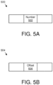
- Figure 5A is a schematic block diagram illustrating one embodiment of a UL grant message 500, which may be substantially similar to the UL grant message 466.
- the UL grant message 500 includes a number 502.
- the number 502 is the number of multiple consecutive UL subframes to be transmitted by the remote unit 102.
- the number may be 1, 2, 3, 4, 5, 6, 7, 8, 9, or 10, to indicate the number of consecutive UL subframes to be transmitted by the remote unit 102 to the base unit 104.
- the number 502 is illustrated as being toward the central portion of the UL grant message 500, the number 502 may be positioned at any location within the UL grant message 500.
- Figure 5B is a schematic block diagram illustrating another embodiment of a UL grant message 504, which may be substantially similar to the UL grant message 466.
- the UL grant message 504 includes an offset 506.
- the offset 506 may be an offset for the last subframe with respect to the starting subframe in the frame period. For example, if the starting subframe is subframe 0, an offset of 1 would represent subframe 1, while the actual number of subframes to be transmitted by the remote unit 102 would be 2. As another example, if the starting subframe is subframe 0 and the last subframe is subframe 6, an offset of 6 would represent subframe 6, while the actual number of subframes to be transmitted by the remote unit 102 would be 7.
- Figure 6 is a schematic flow diagram illustrating one embodiment of a method 600 for burst-based transmission from a base unit 104.
- the method 600 is performed by an apparatus, such as the base unit 104.
- the method 600 may be performed by a processor executing program code for example, a microcontroller, a microprocessor, a CPU, a GPU, an auxiliary processing unit, a FPGA, or the like.
- the method 600 may include determining 602 multiple (e.g, a plurality of) consecutive UL subframes to be transmitted from a remote unit 102 (e.g., UE). For example, the method 600 may determine a number of consecutive subframes that are to be transmitted from the remote unit 102. In certain embodiments, the remote unit 102 may provide a request to the base unit 104 including a number of subframes to be transmitted from the remote unit 102.
- the method 600 may also include forming 604 a UL grant message (e.g., UL grant message 466) to schedule transmission of the multiple consecutive UL subframes.
- forming 604 the UL grant message to schedule transmission of the multiple consecutive UL subframes includes forming the UL grant message to indicate a number (e.g., number 502) of the multiple consecutive UL subframes to be transmitted from the remote unit 102.
- forming the UL grant message to indicate the number of the multiple consecutive UL subframes to be transmitted from the remote unit 102 includes forming the UL grant message to include two bits or four bits to indicate the number of the multiple consecutive UL subframes to be transmitted from the remote unit 102.
- forming 604 the UL grant message to schedule transmission of the multiple consecutive UL subframes includes forming the UL grant message to indicate an offset (e.g., offset 506) for a last subframe of the multiple consecutive UL subframes to be transmitted from the remote unit 102 relative to a starting subframe of the multiple consecutive UL subframes.
- an offset e.g., offset 506
- the method 600 may provide 606 the UL grant message to the remote unit 102. Then the method 600 may end.
- the transmitter 310 of the base unit 104 may provide 606 the UL grant message to the remote unit 102.
- providing 606 the UL grant message to the remote unit 102 may include providing the UL grant message to the remote unit 102 at least four ms before a first subframe in a frame period that is to include the multiple consecutive UL subframes.
- a first UL subframe of the multiple consecutive UL subframes is the first subframe in the frame period.
- a maximum duration of the multiple consecutive UL subframes is a maximum channel occupancy time (e.g., maximum channel occupancy time 438).
- Figure 7 is a schematic flow chart diagram illustrating one embodiment of a method 700 for a remote unit 102 to receive burst-based transmission from a base unit 104.
- the method 700 may be performed by a processor executing program code, for example, a microcontroller, a microprocessor, a CPU, a GPU, an auxiliary processing unit, a FPGA, or the like.
- the method 700 may include receiving 702 a UL grant message (e.g., UL grant message 466). In one embodiment, the receiver 212 of the remote unit 102 may receive the UL grant message. The method 700 may also include determining 704 a frame period to transmit multiple (e.g., a plurality of) consecutive UL subframes based on a portion of the UL grant message. The portion of the UL grant message may be anything that corresponds to the UL grant message including data contained within the UL grant message (e.g., the number 502, the offset 506, etc.), data relating to receipt of the UL grant message (e.g., a time that the UL grant message was received, etc.), and so forth.
- a UL grant message e.g., UL grant message 466
- the method 700 may also include determining 704 a frame period to transmit multiple (e.g., a plurality of) consecutive UL subframes based on a portion of the UL grant message.
- the frame period is at least four ms from the time of the receipt of the UL grant message.
- the frame period to transmit multiple consecutive UL subframes is the frame period that begins after four ms expires, in another embodiment, the UL grant message may specify a delay of any suitable number of frame periods.
- the method 700 may determine 706 a number of the multiple consecutive UL subframes to transmit based on the portion of the UL grant message. In one embodiment, determining 706 the number of the multiple consecutive UL subframes based on the portion of the UL grant message includes identifying the number (e.g., the number 502) of the multiple consecutive UL subframes in the UL grant message. In another embodiment, determining 706 the number of the multiple consecutive UL subframes based on the portion of the UL grant message includes identifying an offset (e.g., the offset 506) for a last subframe of the multiple consecutive UL subframes relative to a starting subframe of the multiple consecutive UL subframes.
- an offset e.g., the offset 506
- the method 700 may include performing 708 a CCA check. In certain embodiments, the remote unit 102 may perform 708 the CCA check. The method 700 then determines 710 whether the CCA check was successful. If the CCA check is not successful, the method 700 may return to receiving 702 a UL grant message. However, if the CCA check is successful, the method 700 then determines 712 whether the number of the multiple consecutive UL subframes is equal to the frame period. If the number of the multiple consecutive UL subframes is equal to the frame period, the method 700 may include reserving 714 the idle period within the last subframe so that only part of the last subframe is used for UL data, then proceeds to transmitting 716. If the number of the multiple consecutive UL subframes is less than the frame period, the method 700 proceeds to transmitting 716 without reserving 714 the idle period.
- the method 700 may include transmitting 716 the number of the multiple consecutive UL subframes starting at a first subframe of the frame period. Then the method 700 may end.
- the transmitter 210 may transmit the number of the multiple consecutive UL subframes starting at the first subframe of the frame period. For example, the transmitter 210 may transmit 2, 3, 4, 5, 6, 7, 8, 9, 10, or more multiple consecutive UL subframes starting at the first subframe of the frame period.
- the method 700 may include using only part of a last subframe of the multiple consecutive UL subframes to transmit data if a transmission time for the number of the multiple consecutive UL subframes is equal to the frame period.
- a maximum duration of the multiple consecutive UL subframes is a maximum channel occupancy time (e.g., maximum channel occupancy time 438).
Landscapes
- Engineering & Computer Science (AREA)
- Signal Processing (AREA)
- Computer Networks & Wireless Communication (AREA)
- Mobile Radio Communication Systems (AREA)
Claims (18)
- Basiseinheit (104), umfassend:einen Prozessor (302);einen Speicher (304), der vom Prozessor ausführbaren Code speichert, sodass die Basiseinheit (104) eingerichtet ist zum:Bestimmen einer Vielzahl aufeinanderfolgender Uplink-Subframes, die von einer Remote-Einheit (102) übertragen werden sollen, wobei die Vielzahl aufeinanderfolgender Uplink-Subframes Teil einer Uplink-Burst-Übertragung ist und in jedem Uplink-Subframe der Vielzahl aufeinanderfolgender Uplink-Subframes dieselbe Frequenzressource und dasselbe Modulationscodierungsschema verwendet werden; undBilden einer LAA-Uplink-Gewährungsnachricht (Licensed Assisted Access, Lizenzierter unterstützter Zugriff) zum Planen einer Übertragung der Vielzahl aufeinanderfolgender Uplink-Subframes, wobei:die LAA-Uplink-Gewährungsnachricht eine Anzahl der Vielzahl aufeinanderfolgender Uplink-Subframes angibt, die von der Remote-Einheit (102) übertragen werden sollen;eine maximale Anzahl aufeinanderfolgender Uplink-Subframes, die durch die LAA-Uplink-Gewährungsnachricht geplant werden, vier beträgt;die aufeinanderfolgenden Uplink-Subframes Teil eines Frames sind, der aus zehn Subframes besteht; unddie LAA-Uplink-Gewährungsnachricht Informationen zum Planen mehrerer aufeinanderfolgender Subframes mit derselben Frequenzressource und demselben Modulationscodierungsschema enthält; undeinen Sender (310), der die LAA-Uplink-Gewährungsnachricht an die Remote-Einheit (102) bereitstellt.
- Basiseinheit (104) nach Anspruch 1, wobei das Bilden der LAA-Uplink-Gewährungsnachricht zum Angeben der Anzahl der Vielzahl aufeinanderfolgender Uplink-Subframes, die von der Remote-Einheit (102) übertragen werden sollen, das Bilden der LAA-Uplink-Gewährungsnachricht umfasst, sodass sie vier Bits enthält, um die Anzahl der Vielzahl aufeinanderfolgender Uplink-Subframes anzugeben, die von der Remote-Einheit (102) übertragen werden sollen.
- Basiseinheit (104) nach Anspruch 1, wobei das Bilden der LAA-Uplink-Gewährungsnachricht zum Angeben der Anzahl der Vielzahl aufeinanderfolgender Uplink-Subframes, die von der Remote-Einheit (102) übertragen werden sollen, das Bilden der LAA-Uplink-Gewährungsnachricht umfasst, sodass sie zwei Bits enthält, um die Anzahl der Vielzahl aufeinanderfolgender Uplink-Subframes anzugeben, die von der Remote-Einheit (102) übertragen werden sollen.
- Basiseinheit (104) nach Anspruch 1, wobei das Bilden der LAA-Uplink-Gewährungsnachricht zum Planen der Übertragung der Vielzahl von aufeinanderfolgenden Uplink-Subframes das Bilden der LAA-Uplink-Gewährungsnachricht zum Angeben eines Versatzes für einen letzten Subframe der Vielzahl von aufeinanderfolgenden Uplink-Subframes, der von der Remote-Einheit (102) übertragen werden soll, relativ zu einem Start-Subframe der Vielzahl von aufeinanderfolgenden Uplink-Subframes umfasst.
- Basiseinheit (104) nach Anspruch 1, die ferner dazu eingerichtet ist, dass der Sender die LAA-Uplink-Gewährungsnachricht mindestens vier Millisekunden vor einem ersten Subframe einer Frame-Periode, die die Vielzahl aufeinanderfolgender Uplink-Subframes einschließen soll, an die Remote-Einheit (102) bereitstellt.
- Verfahren (600), das durch eine Basiseinheit durchgeführt wird, wobei das Verfahren (600) umfasst:Bestimmen (602), durch Verwenden eines Prozessors, einer Vielzahl aufeinanderfolgender Uplink-Subframes, die von einer Remote-Einheit (102) übertragen werden sollen, wobei die Vielzahl aufeinanderfolgender Uplink-Subframes Teil einer Uplink-Burst-Übertragung ist und in jedem Uplink-Subframe der Vielzahl aufeinanderfolgender Uplink-Subframes dieselbe Frequenzressource und dasselbe Modulationscodierungsschema verwendet werden;Bilden (604) einer LAA-Uplink-Gewährungsnachricht (Licensed Assisted Access, Lizenzierter unterstützter Zugriff) zum Planen einer Übertragung der Vielzahl aufeinanderfolgender Uplink-Subframes, wobei:die LAA-Uplink-Gewährungsnachricht eine Anzahl der Vielzahl aufeinanderfolgender Uplink-Subframes angibt, die von der Remote-Einheit (102) übertragen werden sollen;eine maximale Anzahl aufeinanderfolgender Uplink-Subframes, die durch die LAA-Uplink-Gewährungsnachricht geplant werden, vier beträgt;die aufeinanderfolgenden Uplink-Subframes Teil eines Frames sind, der aus zehn Subframes besteht; unddie LAA-Uplink-Gewährungsnachricht Informationen zum Planen mehrerer aufeinanderfolgender Subframes mit derselben Frequenzressource und demselben Modulationscodierungsschema enthält; undBereitstellen (606) der LAA-Uplink-Gewährungsnachricht an die Remote-Einheit (102).
- Verfahren (600) nach Anspruch 6, wobei ein erster Uplink-Subframe der Vielzahl von aufeinanderfolgenden Uplink-Subframes ein erster Subframe einer Frame-Periode ist.
- Verfahren (600) nach Anspruch 6, wobei eine maximale Dauer der Vielzahl aufeinanderfolgender Uplink-Subframes eine maximale Kanalbelegungszeit ist.
- Verfahren (600) nach Anspruch 6, wobei das Bilden (604) der LAA-Uplink-Gewährungsnachricht zum Angeben der Anzahl der Vielzahl aufeinanderfolgender Uplink-Subframes, die von der Remote-Einheit (102) übertragen werden sollen, das Bilden der LAA-Uplink-Gewährungsnachricht umfasst, sodass sie vier Bits enthält, um die Anzahl der Vielzahl aufeinanderfolgender Uplink-Subframes anzugeben, die von der Remote-Einheit (102) übertragen werden sollen.
- Verfahren (600) nach Anspruch 6, wobei das Bilden (604) der LAA-Uplink-Gewährungsnachricht zum Angeben der Anzahl der Vielzahl aufeinanderfolgender Uplink-Subframes, die von der Remote-Einheit (102) übertragen werden sollen, das Bilden der LAA-Uplink-Gewährungsnachricht umfasst, sodass sie zwei Bits enthält, um die Anzahl der Vielzahl aufeinanderfolgender Uplink-Subframes anzugeben, die von der Remote-Einheit (102) übertragen werden sollen.
- Verfahren (600) nach Anspruch 6, wobei das Bilden (604) der LAA-Uplink-Gewährungsnachricht zum Planen der Übertragung der Vielzahl von aufeinanderfolgenden Uplink-Subframes das Bilden der LAA-Uplink-Gewährungsnachricht zum Angeben eines Versatzes für einen letzten Subframe der Vielzahl von aufeinanderfolgenden Uplink-Subframes, der von der Remote-Einheit (102) übertragen werden soll, relativ zu einem Start-Subframe der Vielzahl von aufeinanderfolgenden Uplink-Subframes umfasst.
- Verfahren (600) nach Anspruch 6, wobei das Bereitstellen (606) der LAA-Uplink-Gewährungsnachricht an die Remote-Einheit (102) das Bereitstellen der LAA-Uplink-Gewährungsnachricht an die Remote-Einheit (102) mindestens vier Millisekunden vor einem ersten Subframe einer Frame-Periode, die die Vielzahl von aufeinanderfolgenden Uplink-Unterrahmen enthalten soll, umfasst.
- Remote-Einheit (102), umfassend:einen Empfänger (212), der eine LAA-Uplink-Gewährungsnachricht (Licensed Assisted Access, Lizenzierter unterstützter Zugriff) empfängt;einen Prozessor (202);einen Speicher (204), der vom Prozessor ausführbaren Code speichert, wobei die Remote-Einheit (102) eingerichtet ist zum:Bestimmen einer Frame-Periode zum Übertragen einer Vielzahl aufeinanderfolgender Uplink-Subframes basierend auf einem Teil der LAA-Uplink-Gewährungsnachricht; undBestimmen einer Anzahl der Vielzahl von aufeinanderfolgenden Uplink-Subframes zum Übertragen basierend auf dem Teil der LAA-Uplink-Gewährungsnachricht, wobei die Vielzahl von aufeinanderfolgenden Uplink-Subframes Teil einer Uplink-Burst-Übertragung ist und in jedem Uplink-Subframe der Vielzahl von aufeinanderfolgenden Uplink-Subframes dieselbe Frequenzressource und dasselbe Modulationscodierungsschema verwendet werden, wobei:die LAA-Uplink-Gewährungsnachricht eine Anzahl der Vielzahl aufeinanderfolgender Uplink-Subframes angibt, die von der Remote-Einheit (102) übertragen werden sollen;eine maximale Anzahl aufeinanderfolgender Uplink-Subframes, die durch die LAA-Uplink-Gewährungsnachricht geplant werden, vier beträgt;die aufeinanderfolgenden Uplink-Subframes Teil eines Frames sind, der aus zehn Subframes besteht; unddie LAA-Uplink-Gewährungsnachricht Informationen zum Planen mehrerer aufeinanderfolgender Subframes mit derselben Frequenzressource und demselben Modulationscodierungsschema enthält; undeinen Sender (210), der die Anzahl der Vielzahl aufeinanderfolgender Uplink-Subframes beginnend mit einem ersten Subframe der Frame-Periode überträgt.
- Verfahren (700), das durch eine Remote-Einheit durchgeführt wird, wobei das Verfahren (700) umfasst:Empfangen (702), durch Verwenden eines Prozessors, einer Uplink-Gewährungsnachricht;Bestimmen (704) einer Frame-Periode zum Übertragen einer Vielzahl aufeinanderfolgender Uplink-Subframes basierend auf einem Teil der LAA-Uplink-Gewährungsnachricht;Bestimmen (706) einer Anzahl der Vielzahl von aufeinanderfolgenden Uplink-Subframes zum Übertragen basierend auf dem Teil der LAA-Uplink-Gewährungsnachricht, wobei die Vielzahl von aufeinanderfolgenden Uplink-Subframes Teil einer Uplink-Burst-Übertragung ist und in jedem Uplink-Subframe der Vielzahl von aufeinanderfolgenden Uplink-Subframes dieselbe Frequenzressource und dasselbe Modulationscodierungsschema verwendet werden, wobei:die LAA-Uplink-Gewährungsnachricht eine Anzahl der Vielzahl aufeinanderfolgender Uplink-Subframes angibt, die von der Remote-Einheit (102) übertragen werden sollen;eine maximale Anzahl aufeinanderfolgender Uplink-Subframes, die durch die LAA-Uplink-Gewährungsnachricht geplant werden, vier beträgt;die aufeinanderfolgenden Uplink-Subframes Teil eines Frames sind, der aus zehn Subframes besteht; unddie LAA-Uplink-Gewährungsnachricht Informationen zum Planen mehrerer aufeinanderfolgender Subframes mit derselben Frequenzressource und demselben Modulationscodierungsschema enthält; undÜbertragen (716) der Anzahl der Vielzahl aufeinanderfolgender Uplink-Subframes beginnend mit einem ersten Subframe der Frame-Periode.
- Verfahren (700) nach Anspruch 14, umfassend das Verwenden nur eines Teils eines letzten Subframes der Vielzahl von aufeinanderfolgenden Uplink-Subframes zum Übertragen von Daten, wenn eine Übertragungszeit für die Anzahl der Vielzahl von aufeinanderfolgenden Uplink-Subframes der Frame-Periode entspricht.
- Verfahren (700) nach Anspruch 14, wobei das Bestimmen (706) der Anzahl der Vielzahl aufeinanderfolgender Uplink-Subframes basierend auf dem Teil der LAA-Uplink-Gewährungsnachricht das Identifizieren der Anzahl der Vielzahl aufeinanderfolgender Uplink-Subframes in der LAA-Uplink-Gewährungsnachricht umfasst.
- Verfahren (700) nach Anspruch 14, wobei das Bestimmen (706) der Anzahl der Vielzahl von aufeinanderfolgenden Uplink-Subframes basierend auf dem Teil der LAA-Uplink-Gewährungsnachricht das Identifizieren eines Versatzes für einen letzten Subframe der Vielzahl von aufeinanderfolgenden Uplink-Subframes relativ zu einem Start-Subframe der Vielzahl von aufeinanderfolgenden Uplink-Subframes umfasst.
- Verfahren (700) nach Anspruch 14, wobei eine maximale Dauer der Vielzahl aufeinanderfolgender Uplink-Subframes eine maximale Kanalbelegungszeit ist.
Applications Claiming Priority (1)
| Application Number | Priority Date | Filing Date | Title |
|---|---|---|---|
| PCT/CN2015/086924 WO2017027998A1 (en) | 2015-08-14 | 2015-08-14 | Burst-based transmission scheduling in wireless communication system |
Publications (4)
| Publication Number | Publication Date |
|---|---|
| EP3320738A1 EP3320738A1 (de) | 2018-05-16 |
| EP3320738A4 EP3320738A4 (de) | 2019-03-13 |
| EP3320738B1 true EP3320738B1 (de) | 2024-07-31 |
| EP3320738C0 EP3320738C0 (de) | 2024-07-31 |
Family
ID=58050583
Family Applications (1)
| Application Number | Title | Priority Date | Filing Date |
|---|---|---|---|
| EP15901204.6A Active EP3320738B1 (de) | 2015-08-14 | 2015-08-14 | Auf burst basierende übertragungsplanung in einem drahtloskommunikationssystem |
Country Status (5)
| Country | Link |
|---|---|
| US (1) | US10736133B2 (de) |
| EP (1) | EP3320738B1 (de) |
| KR (1) | KR102234846B1 (de) |
| CN (1) | CN107926027B (de) |
| WO (1) | WO2017027998A1 (de) |
Families Citing this family (5)
| Publication number | Priority date | Publication date | Assignee | Title |
|---|---|---|---|---|
| EP3376814A4 (de) * | 2015-11-12 | 2018-10-31 | Fujitsu Limited | Endgerätevorrichtung, basisstationsvorrichtung, drahtloskommunikationssystem und drahtloskommunikationsverfahren |
| EP3986075A1 (de) | 2016-01-20 | 2022-04-20 | LG Electronics Inc. | Verfahren zur übertragung von uplink-signalen und vorrichtungsunterstützungsverfahren in einem drahtloskommunikationssystem mit unterstützung eines nichtlizenzierten bandes |
| KR102290725B1 (ko) * | 2016-02-02 | 2021-08-19 | 닛본 덴끼 가부시끼가이샤 | Ul 스케줄링 및 ul 송신을 수행하는 방법 및 장치 |
| US10334624B2 (en) * | 2016-04-29 | 2019-06-25 | Ofinno, Llc | Allocation of licensed assisted access resources in a wireless device |
| CN111131060B (zh) * | 2019-12-23 | 2023-07-21 | 瑞斯康达科技发展股份有限公司 | 突发报文的处理方法、装置、电子设备及计算机存储介质 |
Family Cites Families (22)
| Publication number | Priority date | Publication date | Assignee | Title |
|---|---|---|---|---|
| CN101374283B (zh) * | 2007-08-23 | 2012-04-25 | 电信科学技术研究院 | 基站调度用户设备传输上行数据的方法及基站系统 |
| GB2455056A (en) * | 2007-10-04 | 2009-06-03 | Fujitsu Ltd | Signalling mechanism in an OFDMA wireless communication network |
| KR101405946B1 (ko) * | 2007-10-18 | 2014-06-12 | 엘지전자 주식회사 | 광대역 무선접속 시스템에서 자원영역 할당방법 |
| US8422439B2 (en) * | 2008-12-31 | 2013-04-16 | Motorola Mobility Llc | Apparatus and method for communicating control information over a data channel in the absence of user data |
| CN101945464B (zh) | 2009-08-06 | 2014-07-16 | 开曼群岛威睿电通股份有限公司 | 无线传输状态管理的装置、系统及方法 |
| KR20110063276A (ko) * | 2009-12-03 | 2011-06-10 | 엘지전자 주식회사 | 광대역 무선 통신 시스템에서 고정 자원 할당 방법 및 장치 |
| KR101437030B1 (ko) * | 2010-02-25 | 2014-09-02 | 브로드콤 코포레이션 | 4G WiMAX/LTE-WiFi/BT 공존을 위한 시간 도메인 접근에 대한 방법 및 시스템 |
| WO2011112036A2 (ko) * | 2010-03-11 | 2011-09-15 | 엘지전자 주식회사 | 제어 채널의 할당 방법 및 이를 위한 장치 |
| CN103181097B (zh) * | 2010-09-29 | 2016-05-25 | Lg电子株式会社 | 用于在支持多个天线的无线通信系统中的有效反馈的方法和设备 |
| CN104247468A (zh) * | 2011-01-06 | 2014-12-24 | 阿尔戴尔半导体有限公司 | Lte/wi-fi共存 |
| US8675605B2 (en) * | 2011-06-02 | 2014-03-18 | Broadcom Corporation | Frequency hopping in license-exempt/shared bands |
| GB2495991A (en) * | 2011-10-28 | 2013-05-01 | Renesas Mobile Corp | Mapping long term evolution (LTE) control channels to television channel white spaces (TVWS) |
| US9509479B2 (en) * | 2012-08-10 | 2016-11-29 | Lg Electronics Inc. | Method and apparatus for supporting burst transmission in a wireless communication system |
| WO2014098701A1 (en) | 2012-12-21 | 2014-06-26 | Telefonaktiebolaget L M Ericsson (Publ) | Override of multi-tti scheduling messages |
| US9730105B2 (en) * | 2013-05-20 | 2017-08-08 | Qualcomm Incorporated | Listen-before-talk reservation scheme for wireless communications over unlicensed spectrum |
| US9883404B2 (en) * | 2013-06-11 | 2018-01-30 | Qualcomm Incorporated | LTE/LTE—A uplink carrier aggregation using unlicensed spectrum |
| US9924509B2 (en) * | 2013-09-27 | 2018-03-20 | Qualcomm Incorporated | Techniques for configuring an adaptive frame structure for wireless communications using unlicensed radio frequency spectrum |
| US10051660B2 (en) * | 2013-10-03 | 2018-08-14 | Qualcomm Incorporated | Virtual carriers for LTE/LTE-A communications in a shared spectrum |
| US9736829B2 (en) * | 2013-10-14 | 2017-08-15 | Qualcomm Incorporated | Downlink control management in an unlicensed or shared spectrum |
| US20150222408A1 (en) * | 2014-02-04 | 2015-08-06 | Qualcomm Incorporated | Ephich for lte networks with unlicensed spectrum |
| CN104486013B (zh) * | 2014-12-19 | 2017-01-04 | 宇龙计算机通信科技(深圳)有限公司 | 信道检测方法、信道检测系统、终端和基站 |
| KR102467048B1 (ko) * | 2015-04-09 | 2022-11-14 | 한국전자통신연구원 | 히든 노드 문제와 사용자 단말들의 채널 점유를 고려한 상향 링크 데이터 전송 방법 |
-
2015
- 2015-08-14 CN CN201580082480.3A patent/CN107926027B/zh active Active
- 2015-08-14 US US15/752,517 patent/US10736133B2/en active Active
- 2015-08-14 EP EP15901204.6A patent/EP3320738B1/de active Active
- 2015-08-14 KR KR1020187003907A patent/KR102234846B1/ko active IP Right Grant
- 2015-08-14 WO PCT/CN2015/086924 patent/WO2017027998A1/en active Application Filing
Also Published As
| Publication number | Publication date |
|---|---|
| US10736133B2 (en) | 2020-08-04 |
| EP3320738A4 (de) | 2019-03-13 |
| CN107926027B (zh) | 2022-05-31 |
| KR20180031001A (ko) | 2018-03-27 |
| EP3320738A1 (de) | 2018-05-16 |
| EP3320738C0 (de) | 2024-07-31 |
| KR102234846B1 (ko) | 2021-03-31 |
| CN107926027A (zh) | 2018-04-17 |
| US20180242353A1 (en) | 2018-08-23 |
| WO2017027998A1 (en) | 2017-02-23 |
Similar Documents
| Publication | Publication Date | Title |
|---|---|---|
| US11825478B2 (en) | Uplink/downlink scheduling in a wireless communication system | |
| EP4080980B1 (de) | Anzeige von planungsanfragen | |
| US11412529B2 (en) | Determining a transmission scheme | |
| EP3320738B1 (de) | Auf burst basierende übertragungsplanung in einem drahtloskommunikationssystem | |
| US11456816B2 (en) | Flexible uplink/downlink transmissions in a wireless communication system | |
| EP3903435A1 (de) | Harq-ack-übertragung auf unlizenziertem spektrum | |
| US11503571B2 (en) | Grant-free resource allocation | |
| US10979180B2 (en) | Hybrid automatic repeat request acknowledgment bundling | |
| US20180317110A1 (en) | Determining to transition to a connected state |
Legal Events
| Date | Code | Title | Description |
|---|---|---|---|
| STAA | Information on the status of an ep patent application or granted ep patent |
Free format text: STATUS: THE INTERNATIONAL PUBLICATION HAS BEEN MADE |
|
| PUAI | Public reference made under article 153(3) epc to a published international application that has entered the european phase |
Free format text: ORIGINAL CODE: 0009012 |
|
| STAA | Information on the status of an ep patent application or granted ep patent |
Free format text: STATUS: REQUEST FOR EXAMINATION WAS MADE |
|
| 17P | Request for examination filed |
Effective date: 20180209 |
|
| AK | Designated contracting states |
Kind code of ref document: A1 Designated state(s): AL AT BE BG CH CY CZ DE DK EE ES FI FR GB GR HR HU IE IS IT LI LT LU LV MC MK MT NL NO PL PT RO RS SE SI SK SM TR |
|
| AX | Request for extension of the european patent |
Extension state: BA ME |
|
| DAV | Request for validation of the european patent (deleted) | ||
| DAX | Request for extension of the european patent (deleted) | ||
| A4 | Supplementary search report drawn up and despatched |
Effective date: 20190211 |
|
| RIC1 | Information provided on ipc code assigned before grant |
Ipc: H04W 72/12 20090101AFI20190205BHEP Ipc: H04W 16/14 20090101ALN20190205BHEP Ipc: H04L 5/00 20060101ALI20190205BHEP |
|
| STAA | Information on the status of an ep patent application or granted ep patent |
Free format text: STATUS: EXAMINATION IS IN PROGRESS |
|
| STAA | Information on the status of an ep patent application or granted ep patent |
Free format text: STATUS: EXAMINATION IS IN PROGRESS |
|
| 17Q | First examination report despatched |
Effective date: 20200806 |
|
| STAA | Information on the status of an ep patent application or granted ep patent |
Free format text: STATUS: EXAMINATION IS IN PROGRESS |
|
| GRAP | Despatch of communication of intention to grant a patent |
Free format text: ORIGINAL CODE: EPIDOSNIGR1 |
|
| STAA | Information on the status of an ep patent application or granted ep patent |
Free format text: STATUS: GRANT OF PATENT IS INTENDED |
|
| RIC1 | Information provided on ipc code assigned before grant |
Ipc: H04W 16/14 20090101ALN20231130BHEP Ipc: H04W 72/12 20090101AFI20231130BHEP Ipc: H04W 72/23 20230101ALI20231130BHEP Ipc: H04L 5/00 20060101ALI20231130BHEP |
|
| INTG | Intention to grant announced |
Effective date: 20231214 |
|
| RIC1 | Information provided on ipc code assigned before grant |
Ipc: H04W 16/14 20090101ALN20231130BHEP Ipc: H04W 72/23 20230101ALI20231130BHEP Ipc: H04L 5/00 20060101ALI20231130BHEP Ipc: H04W 72/12 20090101AFI20231130BHEP |
|
| GRAJ | Information related to disapproval of communication of intention to grant by the applicant or resumption of examination proceedings by the epo deleted |
Free format text: ORIGINAL CODE: EPIDOSDIGR1 |
|
| STAA | Information on the status of an ep patent application or granted ep patent |
Free format text: STATUS: EXAMINATION IS IN PROGRESS |
|
| GRAP | Despatch of communication of intention to grant a patent |
Free format text: ORIGINAL CODE: EPIDOSNIGR1 |
|
| STAA | Information on the status of an ep patent application or granted ep patent |
Free format text: STATUS: GRANT OF PATENT IS INTENDED |
|
| INTC | Intention to grant announced (deleted) | ||
| RIC1 | Information provided on ipc code assigned before grant |
Ipc: H04W 16/14 20090101ALN20240207BHEP Ipc: H04W 72/23 20230101ALI20240207BHEP Ipc: H04L 5/00 20060101ALI20240207BHEP Ipc: H04W 72/12 20090101AFI20240207BHEP |
|
| INTG | Intention to grant announced |
Effective date: 20240222 |
|
| GRAS | Grant fee paid |
Free format text: ORIGINAL CODE: EPIDOSNIGR3 |
|
| GRAA | (expected) grant |
Free format text: ORIGINAL CODE: 0009210 |
|
| STAA | Information on the status of an ep patent application or granted ep patent |
Free format text: STATUS: THE PATENT HAS BEEN GRANTED |
|
| AK | Designated contracting states |
Kind code of ref document: B1 Designated state(s): AL AT BE BG CH CY CZ DE DK EE ES FI FR GB GR HR HU IE IS IT LI LT LU LV MC MK MT NL NO PL PT RO RS SE SI SK SM TR |
|
| REG | Reference to a national code |
Ref country code: CH Ref legal event code: EP Ref country code: GB Ref legal event code: FG4D |
|
| REG | Reference to a national code |
Ref country code: DE Ref legal event code: R096 Ref document number: 602015089420 Country of ref document: DE |
|
| REG | Reference to a national code |
Ref country code: IE Ref legal event code: FG4D |