EP3320677B1 - Erfassen von schall - Google Patents
Erfassen von schall Download PDFInfo
- Publication number
- EP3320677B1 EP3320677B1 EP16820897.3A EP16820897A EP3320677B1 EP 3320677 B1 EP3320677 B1 EP 3320677B1 EP 16820897 A EP16820897 A EP 16820897A EP 3320677 B1 EP3320677 B1 EP 3320677B1
- Authority
- EP
- European Patent Office
- Prior art keywords
- microphones
- sound
- sound field
- audio
- microphone
- Prior art date
- Legal status (The legal status is an assumption and is not a legal conclusion. Google has not performed a legal analysis and makes no representation as to the accuracy of the status listed.)
- Active
Links
- 230000005236 sound signal Effects 0.000 claims description 29
- 238000012545 processing Methods 0.000 claims description 24
- 238000000034 method Methods 0.000 claims description 14
- 230000001934 delay Effects 0.000 claims description 3
- 230000033458 reproduction Effects 0.000 description 13
- 238000013461 design Methods 0.000 description 12
- 230000000694 effects Effects 0.000 description 6
- 239000004065 semiconductor Substances 0.000 description 6
- 238000006243 chemical reaction Methods 0.000 description 4
- 238000004891 communication Methods 0.000 description 4
- 238000010586 diagram Methods 0.000 description 4
- 230000006870 function Effects 0.000 description 4
- 102100026436 Regulator of MON1-CCZ1 complex Human genes 0.000 description 3
- 101710180672 Regulator of MON1-CCZ1 complex Proteins 0.000 description 3
- 230000011218 segmentation Effects 0.000 description 3
- 238000007619 statistical method Methods 0.000 description 3
- 238000004458 analytical method Methods 0.000 description 2
- 230000008901 benefit Effects 0.000 description 2
- 230000008878 coupling Effects 0.000 description 2
- 238000010168 coupling process Methods 0.000 description 2
- 238000005859 coupling reaction Methods 0.000 description 2
- 230000001419 dependent effect Effects 0.000 description 2
- 238000005516 engineering process Methods 0.000 description 2
- 230000007274 generation of a signal involved in cell-cell signaling Effects 0.000 description 2
- 238000004519 manufacturing process Methods 0.000 description 2
- 230000007246 mechanism Effects 0.000 description 2
- 230000003287 optical effect Effects 0.000 description 2
- 230000008447 perception Effects 0.000 description 2
- 230000008569 process Effects 0.000 description 2
- 238000009877 rendering Methods 0.000 description 2
- 238000000926 separation method Methods 0.000 description 2
- 238000012546 transfer Methods 0.000 description 2
- 230000000007 visual effect Effects 0.000 description 2
- 101100130502 Caenorhabditis elegans mics-1 gene Proteins 0.000 description 1
- OKTJSMMVPCPJKN-UHFFFAOYSA-N Carbon Chemical compound [C] OKTJSMMVPCPJKN-UHFFFAOYSA-N 0.000 description 1
- 230000003044 adaptive effect Effects 0.000 description 1
- 230000003190 augmentative effect Effects 0.000 description 1
- 230000005540 biological transmission Effects 0.000 description 1
- 230000015572 biosynthetic process Effects 0.000 description 1
- 230000000903 blocking effect Effects 0.000 description 1
- 239000003990 capacitor Substances 0.000 description 1
- 229910052799 carbon Inorganic materials 0.000 description 1
- 230000008867 communication pathway Effects 0.000 description 1
- 239000004020 conductor Substances 0.000 description 1
- 238000013500 data storage Methods 0.000 description 1
- 210000005069 ears Anatomy 0.000 description 1
- 230000002452 interceptive effect Effects 0.000 description 1
- 230000006855 networking Effects 0.000 description 1
- 230000004044 response Effects 0.000 description 1
- 230000003595 spectral effect Effects 0.000 description 1
- 239000000758 substrate Substances 0.000 description 1
- 238000003786 synthesis reaction Methods 0.000 description 1
- 230000001755 vocal effect Effects 0.000 description 1
Images


Classifications
-
- H—ELECTRICITY
- H04—ELECTRIC COMMUNICATION TECHNIQUE
- H04S—STEREOPHONIC SYSTEMS
- H04S7/00—Indicating arrangements; Control arrangements, e.g. balance control
-
- H—ELECTRICITY
- H04—ELECTRIC COMMUNICATION TECHNIQUE
- H04R—LOUDSPEAKERS, MICROPHONES, GRAMOPHONE PICK-UPS OR LIKE ACOUSTIC ELECTROMECHANICAL TRANSDUCERS; DEAF-AID SETS; PUBLIC ADDRESS SYSTEMS
- H04R1/00—Details of transducers, loudspeakers or microphones
- H04R1/005—Details of transducers, loudspeakers or microphones using digitally weighted transducing elements
-
- H—ELECTRICITY
- H04—ELECTRIC COMMUNICATION TECHNIQUE
- H04R—LOUDSPEAKERS, MICROPHONES, GRAMOPHONE PICK-UPS OR LIKE ACOUSTIC ELECTROMECHANICAL TRANSDUCERS; DEAF-AID SETS; PUBLIC ADDRESS SYSTEMS
- H04R1/00—Details of transducers, loudspeakers or microphones
- H04R1/20—Arrangements for obtaining desired frequency or directional characteristics
- H04R1/32—Arrangements for obtaining desired frequency or directional characteristics for obtaining desired directional characteristic only
- H04R1/40—Arrangements for obtaining desired frequency or directional characteristics for obtaining desired directional characteristic only by combining a number of identical transducers
- H04R1/406—Arrangements for obtaining desired frequency or directional characteristics for obtaining desired directional characteristic only by combining a number of identical transducers microphones
-
- H—ELECTRICITY
- H04—ELECTRIC COMMUNICATION TECHNIQUE
- H04R—LOUDSPEAKERS, MICROPHONES, GRAMOPHONE PICK-UPS OR LIKE ACOUSTIC ELECTROMECHANICAL TRANSDUCERS; DEAF-AID SETS; PUBLIC ADDRESS SYSTEMS
- H04R3/00—Circuits for transducers, loudspeakers or microphones
- H04R3/005—Circuits for transducers, loudspeakers or microphones for combining the signals of two or more microphones
-
- H—ELECTRICITY
- H04—ELECTRIC COMMUNICATION TECHNIQUE
- H04R—LOUDSPEAKERS, MICROPHONES, GRAMOPHONE PICK-UPS OR LIKE ACOUSTIC ELECTROMECHANICAL TRANSDUCERS; DEAF-AID SETS; PUBLIC ADDRESS SYSTEMS
- H04R5/00—Stereophonic arrangements
- H04R5/027—Spatial or constructional arrangements of microphones, e.g. in dummy heads
-
- H—ELECTRICITY
- H04—ELECTRIC COMMUNICATION TECHNIQUE
- H04S—STEREOPHONIC SYSTEMS
- H04S7/00—Indicating arrangements; Control arrangements, e.g. balance control
- H04S7/30—Control circuits for electronic adaptation of the sound field
-
- H—ELECTRICITY
- H04—ELECTRIC COMMUNICATION TECHNIQUE
- H04R—LOUDSPEAKERS, MICROPHONES, GRAMOPHONE PICK-UPS OR LIKE ACOUSTIC ELECTROMECHANICAL TRANSDUCERS; DEAF-AID SETS; PUBLIC ADDRESS SYSTEMS
- H04R2201/00—Details of transducers, loudspeakers or microphones covered by H04R1/00 but not provided for in any of its subgroups
- H04R2201/40—Details of arrangements for obtaining desired directional characteristic by combining a number of identical transducers covered by H04R1/40 but not provided for in any of its subgroups
- H04R2201/401—2D or 3D arrays of transducers
-
- H—ELECTRICITY
- H04—ELECTRIC COMMUNICATION TECHNIQUE
- H04R—LOUDSPEAKERS, MICROPHONES, GRAMOPHONE PICK-UPS OR LIKE ACOUSTIC ELECTROMECHANICAL TRANSDUCERS; DEAF-AID SETS; PUBLIC ADDRESS SYSTEMS
- H04R2430/00—Signal processing covered by H04R, not provided for in its groups
- H04R2430/20—Processing of the output signals of the acoustic transducers of an array for obtaining a desired directivity characteristic
-
- H—ELECTRICITY
- H04—ELECTRIC COMMUNICATION TECHNIQUE
- H04S—STEREOPHONIC SYSTEMS
- H04S2400/00—Details of stereophonic systems covered by H04S but not provided for in its groups
- H04S2400/11—Positioning of individual sound objects, e.g. moving airplane, within a sound field
-
- H—ELECTRICITY
- H04—ELECTRIC COMMUNICATION TECHNIQUE
- H04S—STEREOPHONIC SYSTEMS
- H04S2400/00—Details of stereophonic systems covered by H04S but not provided for in its groups
- H04S2400/15—Aspects of sound capture and related signal processing for recording or reproduction
-
- H—ELECTRICITY
- H04—ELECTRIC COMMUNICATION TECHNIQUE
- H04S—STEREOPHONIC SYSTEMS
- H04S2420/00—Techniques used stereophonic systems covered by H04S but not provided for in its groups
- H04S2420/01—Enhancing the perception of the sound image or of the spatial distribution using head related transfer functions [HRTF's] or equivalents thereof, e.g. interaural time difference [ITD] or interaural level difference [ILD]
Definitions
- the present application relates to capturing of sound for spatial processing of audio signals to enable spatial reproduction of audio signals.
- Spatial audio comprises capturing and processing audio signals in order to provide the perception of audio content based on directional information and ambient information of a sound field.
- Spatial processing may be implemented within applications such as spatial sound reproduction.
- the aim of spatial sound reproduction is to reproduce the perception of spatial aspects of a sound field. These include the direction, the distance, and the size of the sound source, as well as properties of the surrounding physical space.
- Sound capturing devices may need a human operator to point them towards sound content of interest. Handling (e.g. turning) of the device, by a human operator or otherwise, may cause undesired interference signal. The operator may also cause acoustic shadowing.
- EP 1 377 041 A2 discloses an integrated design for an omni-directional camera and microphone array. More specifically, the disclosed invention is directed towards an integrated omni-directional camera and microphone array that can be used for teleconferencing and meeting recording.
- WO 2010/125228 A1 relates to multiview audio signals, and more particularly to encoding, transmission and reconstruction of multiview audio signals.
- the following describes in further detail suitable apparatus and possible mechanisms for the provision of effective sound capture for spatial signal processing.
- the herein described examples relate to the field of audio presence capture by an apparatus comprising a multiple of microphones.
- spatial audio field around an apparatus with microphones is captured in all directions, or at least substantially in all directions, around the device to produce presence capture of a sound field.
- the capture can be provided, in addition to around the device on a horizontal plane, all directions above and below.
- the capture can be provided along all three axis of a coordinate system.
- Microphones can be placed according to a predetermined geometry on the apparatus so that it is possible to record audio from all directions and so that the auditory shadowing effect of the body of the apparatus is minimized.
- the plurality of microphones is forming substantially a cube geometry or a cube like geometry. Each microphone is located at a corner of the geometry where three surfaces of the cube or cube like geometry meet. In other example embodiments, other geometry shapes can be formed by the location of the plurality of microphones. It is understood that the apparatus contains the geometry by the plurality of microphones.
- the plurality of microphones can be arranged outside or inside the apparatus in a geometric configuration.
- the configuration can be a pre-determined configuration so as to capture a presence of sound field from all directions.
- the microphones are arranged symmetrically so that microphones capture the audio regardless the direction the sound is coming from.
- the microphones are placed symmetrically so that at least some microphone pairs are provided that have a symmetrical shadowing effect and auditory delays from the body. The symmetric positioning assists in preserving good quality audio by making processing the audio signals easier, and providing, at least in some directions, each ear a similar sounding audio.
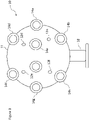
- Figure 1 illustrates a schematic presentation of an apparatus comprising a pre-determined geometric configuration for the plurality of microphones as disclosed herein. More particularly, Figure 1 shows a possible arrangement of eight positioned in the corners of a cuboid. In this way there are microphones with only a small shadowing effect from the body in all directions around the body of the apparatus. It shall be understood that such pre-determined geometric configuration can be contained inside any shape of a portable electronic device.
- the geometry of microphone locations is arranged such that at least four microphones is always visible from any direction.
- the arrangement can be such that an identical pattern of microphones is visible in x, y and z axis direction.
- microphone what is a visible part of a microphone and what part of a microphone captures the sound it is noted that the visible parts referred to herein are not necessarily the physical microphone components but a viewer could see only sound outlet/s for each microphone from each viewing angle (right-left-top-bottom-front-behind). Such outlets, for example holes on the body, can be only acoustically coupled to respective microphone components. Nevertheless, in the context of this disclosure these parts shall be understood to be covered by the general term microphone.
- the term microphone is used throughout to refer to any part of a physical microphone arrangement providing a part of the geometrical arrangement of microphones by which sound can be captured from substantially all around the body of the apparatus.
- the body has a substantially spherical shape.
- Figure 1 the ball like shape of the body is illustrated with the two circles to indicate an approximately spherical shape.
- the shape can be designed to have a suitably shaped extension, for example in the form of a holder, for handling of the apparatus.
- the extension can be designed so as to avoid interfering, in use, with the plurality of microphones, and the plurality of camera modules, if provided.
- the microphones can have separation in all directions (x, y, z) to be able to capture all directions. This may require capture by a minimum of four microphones.
- the microphone may need to be positioned such that they are not on the same plane.
- Microphone pairs may also be provided such that multiple pairs of microphones can be used to estimate sound directions from a plurality of directions around the device. Statistical analysis can be used to merge the multiple pair direction estimates into one. Information on ambience sounds can also be produced. Alternatively, all eight microphones can be used for capturing the sound field. It is understood that a directional information of a sound source in a sound field and an ambience information of the sound field can be determined by using all eight microphones.
- the plurality of microphones are arranged in a geometrical shape in such a way that sound outlet/s of at least 4 microphones can be visually seen from a viewing direction whilst other microphones are shadowed in the same viewing direction.
- other arrangements can be provided so that 2 of the plurality of microphones can be substantially shadowed from substantially all viewing directions. It is understood that this kind of positional microphone arrangement provides particular benefits in capturing and reproduction. For example, at least some or all non-shadowed microphones can be used for the mid signal determination (and generation) whereas at least some or all shadowed microphones are used for the side signal determination (and generation).
- the apparatus can also be adapted to capture video at the same time.
- the video capture can also be substantially around all directions.
- the positioning and/or number of microphones can be dependent on the positioning and/or number of cameras.
- the device can thus be configured to capture both audio and video information from all directions in order to capture an enhanced presence of visual and sound fields.
- the position of the microphones, and cameras if these are provided, makes possible to record audio, and the possible video, substantially from all directions.
- the configuration can be such that the apparatus does not need to be rotated or otherwise moved when interesting audio, and possible video, content moves around the device.
- the plurality of microphones may also be arranged relative to a plurality of second type of sensors.
- motion sensors may be provided.
- the directional part of the sound field, the direction of the sound field and/or the ambient part of the sound field can be captured.
- the captured information can be stored, at least temporarily, and used in dependence of the circumstances of the listener, for example based on viewing direction and/or position of the listener. Examples for this will be explained in more detail later in this description.
- the apparatus can be designed and dimensioned so that it is portable.
- the portable presence capture device can have microphones all around the device to be able to capture audio from all directions with minimal shadowing effects by the device.
- the apparatus is classified as portable, it can be positioned or fixed at a location.
- the apparatus can be interfaced with another mechanical part.
- the apparatus can have a preferred direction. Means for directing the apparatus by a user may also be provided.
- FIG. 2 and 3 An example of an audio capturing device 10 configured according to the herein disclosed principles is shown in Figures 2 and 3 from two directions.
- the device 10 is shown to have roughly a spherically shaped body 11. However, other shapes may also be used.
- the body of the device may be, for example, about 10 - 30cm in diameter. However, this range is just an example, and other sizes, even sizes of a totally different magnitude are also possible.
- the device is provided with a plurality of microphones, Figures 2 and 3 showing microphones 12a - 12f.
- device 10 has eight microphones placed symmetrically around the body thereof.
- the microphones may be omnidirectional or directional (such as cardioids).
- the directions of the directional microphones can be arranged to approximately cover all directions around the device.
- a plurality of cameras 14a - 14h is also provided.
- Device 10 has eight cameras capable of capturing video image and covering the entire surrounding of the device. It is noted that a different number of cameras may be used, depending on the application.
- the device can have a preferred viewpoint. In Figure 2 this is indicated by arrow 13.
- the preferred viewpoint may be one where the device works best and/or where playback of files or stream captured by the device is started when the captured multimedia is viewed using e.g. a mobile device, head mounted display, computer screen, virtual reality environment with many displays and so on.
- the preferred viewpoint may be indicated by the shape of the device.
- a protruding element may be provided in the shape of the otherwise mostly symmetric device to point towards or away from the preferred viewpoint.
- this is provided by a protruding element 16 extending from the otherwise spherical body.
- the element 16 also provide handle for a user to direct and/or move the device around.
- the preferred direction may also be indicated by an appropriate marking on the device. In this way the user intuitively knows the preferred orientation of the device.
- the microphones are symmetrically placed on the body to help produce symmetric shadowing by the device body for good sounding audio (at least in some viewing directions).
- at least some subsets of microphones are symmetrically placed.
- Symmetric arrangement can be provided by pairs of microphones or by all microphones. Symmetric placements may also help in creating signals where the delays from different sound sources around the device are symmetric. This can make analysis of the sound source directions easier, and also can make the signals reproduced accurately by producing symmetric signals to both ears. This can be provided at least in certain viewing directions.
- the device may contain its own power source, processor(s), memory, wireless networking capability etc. In some cases the device may be connected to a power supply and cable network.
- Figures 2 and 3 show also a stand 18. This can be of any shape and design, for example a tripod, a pivoted arm, a rotatable arm and so forth. It is also possible to have a capturing device with no stand.
- the microphones can be arranged in various directions. Below are certain examples where the center of the device is considered to provide the origin (see Figure 1 ) and where zero degrees for both azimuth and elevation is the preferred viewpoint direction. In the tables below left column is the azimuth and the right column is the elevation in degrees.
- the wires from the device microphones to the processor(s) may be symmetric so that any disturbance caused by the device electronics is similar in all microphone signals. This can be provide advantage in processing the microphone signals because the differences between them are caused more by the relative positions of the microphones to the sound sources than the device electronics.
- the microphone inlets and device shape around the inlets may be similar. This helps in processing the microphone signals because the differences between them are caused more by the relative positions of the microphones to the sound sources than the shape of the inlets and the shape of the device.
- a single final direction estimate is the estimated from the multitude of directions using statistic processing (e.g. mean or median direction).
- Microphones may be placed relative to a multiple of cameras so that each camera in the device has a subset of microphones positioned similarly around it. This can be advantageous for example in a case where viewpoints are used directly instead of using video processing to create viewpoints in between the cameras. When viewpoints are used in this way and the microphones are placed similarly with respect to each camera, the audio properties are similar regardless of which camera is being used.
- the microphones are located in such a way that when a sound source is substantially located on-axis (along either x, y, z, -x, -y or -z axis, see Figure 1 ) from the electronic device, the electronic device is able to substantially point at least four microphones (and accordingly microphone outlet/s for respective microphones) towards the direction of the sound source.
- the microphones can be arranged in a substantially symmetrical configuration in view of each axis direction, Figure 1 showing an example of such configuration. For example, there can be four pairs of microphones (Mic1, Mic2), (Mic3, Mic4), (Mic5, Mic6) and (Mic7, Mic9) that all point to z-axis direction. This enables easy beamforming towards z (and -z) axis directions. Also, this configuration can be advantageously used for estimating sound source direction using the time differences when the sound arrives in each microphone.
- the device can capture many aspects of the spatial sound field. For example: the directional part of the sound field, the direction of a sound source in the sound field and the ambient part of the sound field.
- the directional part can be captured using beamforming or for example methods presented in GB patent application 1511949.8 .
- the GB application discloses certain examples how it is possible to generate at least one mid signal configured to represent the audio source information and at least two side signals configured to represent the ambient audio information.
- the captured component can be stored and/or processed separately. Acoustical shadowing effect may be exploited with respect to certain embodiments to improve the audio quality by offering improved spatial source separation for sounds originating from different directions and employing multiple microphones around the acoustically shadowing object.
- the mid signal can be created using adaptively selected subsets of available microphones and the multiple side signals using multiple microphones.
- the mid signal can be created adaptively based on an estimated direction of arrival (DOA).
- DOA estimated direction of arrival
- the microphone 'nearest' or 'nearer' to the estimated DOA may be selected as a 'reference' microphone.
- the other selected microphone audio signals can then be time aligned with the audio signal from the 'reference' audio signal.
- the time-aligned microphone signals may then be summed to form the mid signal. It is also possible that the selected microphone audio signals are weighted based on the estimated DOA to avoid discontinuities when changing from one microphone subset to another.
- the side signals may be created by using two or more microphones for creating the multiple side signals.
- the microphone audio signals can be weighted with an adaptive time-frequency-dependent gain. These weighted audio signals may be convolved with a predetermined decorrelator or filter configure to decorrelate the audio signals.
- the generation of the multiple audio signals may further comprise passing the audio signal through a suitable presentation or reproduction related filter.
- the audio signals may be passed through a head related transfer function (HRTF) filter where earphones or earpiece reproduction is expected or a multi-channel loudspeaker transfer function filter where loudspeaker presentation is expected.
- HRTF head related transfer function
- a subset of the microphones are used for capturing the directional part.
- the number of microphones and which microphones are used depend on the characteristics of the sound e.g. on the direction of the sound.
- the direction of the sound may be estimated for example using multilateration that is based on the time differences when a sound from a sound source arrives at different microphones. The time differences may be estimated using correlation.
- a subset of the microphones is used for estimating the direction of the sound sources. The direction may be estimated separately for short time segments (typically 20ms) and for many frequency bands (for example third octave bands, Bark bands or similar).
- the number of microphones and which microphones are used may depend on the characteristics of the sound. For example, one might first make an initial estimate using all microphones and then make a more reliable estimate using the microphones that are on the same side of the device as the initial estimated source direction was. Another example method can be found in US publication 2012/0128174 .
- the ambience is estimated using all microphones.
- All the methods can work based on a frequency band segmentation, time segmentation and directional segmentation so that the directional signal, directional information and ambience signal are different in each combination of segments.
- Audio captured by the device may be stored, transmitted and/or streamed as such or converted to some other audio representation.
- the audio may also be compressed using existing or future audio codecs such as mp3, MPEG AAC, Dolby AC-3, MPEG SAOC, etc.
- the audio data can be in the form of direct microphone signals thus leaving the rendering into a suitable reproduction method (stereo speakers, 5.1 speakers, more complex speaker setups with "height speakers", headphones etc.), the audio data can be in the form of already made 5.1, 7.1 signals etc., the audio data can be in the form multiple parallel signals (e.g.
- the audio data can be in the form of one or more directional signals + directional information + one or more ambient signals (this form again leaves rendering to a suitable reproductions method such as 5.1, binaural etc. to be done at the device that receives the "directional + directional information + ambient representation"; GB patent application 1511949.8 , and US publications 2012/0128174 and 2013/0044884 give examples how this can be done).
- the captured audio data may also be reproduced by a device with build in speakers or through headphones (possibly as a binaural signal) or by a mobile phone, tablet, laptop, PC etc.
- a possibility for reproducing the data captured by the herein described apparatus is by a head mounted display with headphones so that the user viewing and listening to the data can turn his head and experience all directions in audio, and also in video, if this capability is provided.
- the produced information of the captured sound can be advantageously used in augmented reality applications.
- a listener / viewer may even be provided with real time stream of video and audio.
- video and audio can track the real life situation.
- a mechanical or wireless connector may also be provided so as to enable an interface mechanism.
- the device can be freely rotated and positioned in any direction as desired.
- the design can comprise a holder and/or a base parts but in other example embodiments such holder and/or base parts may not be required.
- the size of a portable capturing device can have any dimensions, for example, the length, width and height can be designed at around 15-30 cm for a symmetrical shape portable design. The total length, height, width dimensions may be enlarged due to the holder or handling parts as mentioned above.
- the size of the portable device can be influenced by the number of mentioned plurality of microphones and/or camera modules.
- the size of the portable device can also be influenced by the pre-determined geometric microphone configuration.
- An audio capture device may comprise various additional features, such as an internal battery or connectivity for an external battery, an internal charger or connectivity for an external charger, one or more suitable connectors such as micro USB, AV jack, memory card, HDMI, DisplayPort, DVI, RCA, XLR, 3.5mm plug, 1 ⁇ 4" plug etc., one or more processors including DSP algorithms etc., internal memory, wired and/or wireless connectivity modules such as LAN, BT, WLAN, infrared etc., cameras, display such as LCD, speakers, and other sensors such as GPS, accelerometers, touch sensors and so on.
- suitable connectors such as micro USB, AV jack, memory card, HDMI, DisplayPort, DVI, RCA, XLR, 3.5mm plug, 1 ⁇ 4" plug etc.
- processors including DSP algorithms etc.
- internal memory such as LAN, BT, WLAN, infrared etc.
- display such as LCD, speakers, and other sensors such as GPS, accelerometers, touch sensors and so on.
- a presence capture device can be provided where audio and its direction is recorded from all directions around the device. Orientation of the device does not need to be changed, e.g. the device does not need to be rotated when sound sources (and visual sources) of interest move around the device because the device records all directions simultaneously.
- Microphone locations enable using statistical analysis for improving sound direction analysis. Symmetrical device shape and microphone locations and similar inlets and wiring all contribute to microphone signals that are easier to analyze and sound better. Unlike in the prior art where devices cannot capture sound and video from all directions, thus missing some potentially interesting content, the device can be arranged to capture all sound in its surrounding.
- the device Since the device does not need to be turned during capture, handling the device that could cause handling noise and can require a user near the device causing added acoustic shadowing effect can be avoided.
- the device is easy to use. The user does not necessary need to have a professional sound technician level understanding of spatial sound processing. Instead, the user can position the device, and accordingly the configured geometry of the microphones so that the device electronics can process the required information for accurate spatial audio capturing and reproduction of the captured sound.
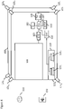
- FIG 4 shows an example for internal components of audio capture apparatus suitable for implementing some embodiments.
- the audio capture apparatus 100 comprises a microphone array 101.
- the microphone array 101 comprises a plurality (for example a number N) of microphones.
- the example shown in Figure 4 shows the microphone array 101 comprising eight microphones 121 1 to 121 8 organised in a hexahedron configuration.
- the microphones may be organised such that they are located at the corners of an audio capture device casing such that the user of the audio capture apparatus 100 may use and/or hold the apparatus without covering or blocking any of the microphones.
- the microphones 121 are shown configured to convert acoustic waves into suitable electrical audio signals.
- the microphones 121 are capable of capturing audio signals and each outputting a suitable digital signal.
- the microphones or array of microphones 121 can comprise any suitable microphone or audio capture means, for example a condenser microphone, capacitor microphone, electrostatic microphone, Electret condenser microphone, dynamic microphone, ribbon microphone, carbon microphone, piezoelectric microphone, or microelectrical-mechanical system (MEMS) microphone.
- the microphones 121 can in some embodiments output the audio captured signal to an analogue-to-digital converter (ADC) 103.
- ADC analogue-to-digital converter
- the audio capture apparatus 100 may further comprise an analogue-to-digital converter 103.
- the analogue-to-digital converter 103 may be configured to receive the audio signals from each of the microphones 121 in the microphone array 101 and convert them into a format suitable for processing.
- the microphones 121 may comprise an ASIC where such-analogue-to-digital conversions may take place in each microphone.
- the analogue-to-digital converter 103 can be any suitable analogue-to-digital conversion or processing means.
- the analogue-to-digital converter 103 may be configured to output the digital representations of the audio signals to a processor 107 or to a memory 111.
- the audio capture apparatus 100 electronics can also comprise at least one processor or central processing unit 107.
- the processor 107 can be configured to execute various program codes.
- the implemented program codes can comprise, for example, spatial processing, mid signal generation, side signal generation, time-to-frequency domain audio signal conversion, frequency-to-time domain audio signal conversions and other algorithmic routines.
- the audio capture apparatus can further comprise a memory 111.
- the at least one processor 107 can be coupled to the memory 111.
- the memory 111 can be any suitable storage means.
- the memory 111 can comprise a program code section for storing program codes implementable upon the processor 107.
- the memory 111 can further comprise a stored data section for storing data, for example data that has been processed or to be processed. The implemented program code stored within the program code section and the data stored within the stored data section can be retrieved by the processor 107 whenever needed via the memory-processor coupling.
- the audio capture apparatus can also comprise a user interface 105.
- the user interface 105 can be coupled in some embodiments to the processor 107.
- the processor 107 can control the operation of the user interface 105 and receive inputs from the user interface 105.
- the user interface 105 can enable a user to input commands to the audio capture apparatus 100, for example via a keypad.
- the user interface 105 can enable the user to obtain information from the apparatus 100.
- the user interface 105 may comprise a display configured to display information from the apparatus 100 to the user.
- the user interface 105 can in some embodiments comprise a touch screen or touch interface capable of both enabling information to be entered to the apparatus 100 and further displaying information to the user of the apparatus 100.
- the audio capture apparatus 100 comprises a transceiver 109.
- the transceiver 109 in such embodiments can be coupled to the processor 107 and configured to enable a communication with other apparatus or electronic devices, for example via a wireless or fixed line communications network.
- the transceiver 109 or any suitable transceiver or transmitter and/or receiver means can in some embodiments be configured to communicate with other electronic devices or apparatus via a wireless or wired coupling.
- the transceiver 109 can communicate with further apparatus by any suitable known communications protocol.
- the transceiver 109 or transceiver means can use a suitable universal mobile telecommunications system (UMTS) protocol, a wireless local area network (WLAN) protocol such as for example IEEE 802.X, a suitable short-range radio frequency communication protocol such as Bluetooth, or infrared data communication pathway (IRDA).
- UMTS universal mobile telecommunications system
- WLAN wireless local area network
- IRDA infrared data communication pathway
- the audio capture apparatus 100 may also comprise a digital-to-analogue converter 113.
- the digital-to-analogue converter 113 may be coupled to the processor 107 and/or memory 111 and be configured to convert digital representations of audio signals (such as from the processor 107) to a suitable analogue format suitable for presentation via an audio subsystem output.
- the digital-to-analogue converter (DAC) 113 or signal processing means can in some embodiments be any suitable DAC technology.
- the audio subsystem can comprise in some embodiments an audio subsystem output 115.
- An example as shown in Figure 4 is a pair of speakers 131 1 and 131 2 .
- the speakers 131 can in some embodiments be configured to receive the output from the digital-to-analogue converter 113 and present the analogue audio signal to the user.
- the speakers 131 can be representative of a headset, for example a set of earphones, or cordless earphones.
- the audio capture apparatus 100 is shown operating within an environment or audio scene wherein there are multiple audio sources present.
- the environment comprises a first audio source 151, a vocal source such as a person talking at a first location.
- the environment shown in Figure 4 comprises a second audio source 153, an instrumental source such as a trumpet playing, at a second location.
- the first and second locations for the first and second audio sources 151 and 153 respectively may be different.
- the first and second audio sources may generate audio signals with different spectral characteristics.
- the audio capture apparatus 100 is shown having both audio capture and audio presentation components, it would be understood that the apparatus 100 can comprise just the audio capture elements such that only the microphones (for audio capture) are present. Similarly in the following examples the audio capture apparatus 100 is described being suitable to performing the spatial audio signal processing described hereafter.
- the audio capture components and the spatial signal processing components may also be separate. In other words the audio signals may be captured by a first apparatus comprising the microphone array and a suitable transmitter. The audio signals may then be received and processed in a manner as described herein in a second apparatus comprising a receiver and processor and memory.
- Figure 5 is a schematic block diagram illustrating processing of signals from multiple microphones to output signals on two channels. Other multi-channel reproductions are also possible. In addition to input from the microphones, input regarding head orientation can be used by the spatial synthesis.
- the components can be arranged in various different manners.
- everything left of the dashed line takes place in the presence capture device, and everything right of the Direct/Ambient signals takes place in a viewing / listening device, for example a head mounted display with headphones, a tablet, mobile phone, laptop and so on.
- the direct signals, ambient signals and directional information can be coded/stored/streamed/transmitted to the viewing device.
- the presence capture device can comprise a display and a headphone connector (e.g. a 1/4" plug) for viewing the captured media.
- the direct signals, ambient signals and directional information are coded/stored in the presence capture device.
- the user viewing the media has preferably a head mounted device with headphones which switches between the output signals 32 depending on the direction the user is looking to.
- a head mounted device with headphones which switches between the output signals 32 depending on the direction the user is looking to.
- This can be provided for a mobile phone, tablet, laptop etc.
- the direction the user is looking at is detected using e.g. a head tracker in a head mounted device, or accelerometer/mouse/touchscreen in a mobile phone, tablet, laptop etc.
- the output signals 32 can be coded/stored/streamed/transmitted to the viewing device.
- the microphone signals as such are coded/stored/streamed/transmitted to the viewing device.
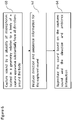
- Figure 6 is a flowchart for a method for capturing sound.
- sound is captured at 60 by a plurality of microphones located in a predetermined geometry relative to a body of a capture apparatus substantially from all directions around the body.
- direction and ambience information is produced for the captured sound. Reproduction of the sound takes then place at 64.
- aspects may be implemented in hardware, while other aspects may be implemented in firmware or software which may be executed by a controller, microprocessor or other computing device, although the invention is not limited thereto. While various aspects of the invention may be illustrated and described as block diagrams, flow charts, or using some other pictorial representation, it is well understood that these blocks, apparatus, systems, techniques or methods described herein may be implemented in, as non-limiting examples, hardware, software, firmware, special purpose circuits or logic, general purpose hardware or controller or other computing devices, or some combination thereof.
- a computer software executable by a data processor such as in the processor entity, or by hardware, or by a combination of software and hardware may be provided.
- any blocks of the logic flow as in the Figures may represent program steps, or interconnected logic circuits, blocks and functions, or a combination of program steps and logic circuits, blocks and functions.
- the software may be stored on such physical media as memory chips, or memory blocks implemented within the processor, magnetic media such as hard disk or floppy disks, and optical media such as for example DVD and the data variants thereof, CD.
- the memory may be of any type suitable to the local technical environment and may be implemented using any suitable data storage technology, such as semiconductor-based memory devices, magnetic memory devices and systems, optical memory devices and systems, fixed memory and removable memory.
- the data processors may be of any type suitable to the local technical environment, and may include one or more of general purpose computers, special purpose computers, microprocessors, digital signal processors (DSPs), application specific integrated circuits (ASIC), gate level circuits and processors based on multi-core processor architecture, as non-limiting examples.
- Embodiments of the inventions may be practiced in various components such as integrated circuit modules.
- the design of integrated circuits is by and large a highly automated process.
- Complex and powerful software tools are available for converting a logic level design into a semiconductor circuit design ready to be etched and formed on a semiconductor substrate.
- Programs such as those provided by Synopsys, Inc. of Mountain View, California and Cadence Design, of San Jose, California automatically route conductors and locate components on a semiconductor chip using well established rules of design as well as libraries of pre-stored design modules.
- the resultant design in a standardized electronic format (e.g., Opus, GDSII, or the like) may be transmitted to a semiconductor fabrication facility or "fab" for fabrication.
Claims (11)
- Einrichtung, die Folgendes umfassteinen Körper,eine Vielzahl von Mikrofonen (121), die in einer vorbestimmten Geometrie relativ zum Körper symmetrisch angeordnet sind, derart, dass die Einrichtung dazu ausgelegt ist, auf Basis der vorbestimmten Geometrie im Wesentlichen aus allen Richtungen um den Körper ein Schallfeld zu erfassen, wobei die Vielzahl von Mikrofonen in der vorbestimmten Geometrie relativ zum Körper derart angeordnet sind, dass das Schallfeld aus einer beliebigen Richtung um den Körper dazu ausgelegt ist, via mindestens vier Mikrofone der Vielzahl von Mikrofonen (121) ohne wesentliche akustische Abschattung durch den Körper erfasst zu werden und via andere Mikrofone der Vielzahl von Mikrofonen (121) mit akustischer Abschattung durch den Körper erfasst zu werden; undeine Elektronik zum Verarbeiten von Signalen von der Vielzahl von Mikrofonen, wo die Elektronik dazu ausgelegt ist, mindestens teilweise auf Basis der von der Vielzahl von Mikrofonen (121) empfangenen Signale Umgebungsinformationen über das Schallfeld und mindestens teilweise auf Basis der von den mindestens vier Mikrofonen der Vielzahl von Mikrofonen (121) ohne wesentliche akustische Abschattung empfangenen Signale Richtungsinformationen von mindestens einer Schallquelle in dem Schallfeld um den Körper zu bestimmen.
- Einrichtung nach Anspruch 1, die eine Vielzahl von Sensoren umfasst, wobei die vorbestimmte Geometrie und/oder die Vielzahl von Mikrofonen, die die vorbestimmte Geometrie bilden, von einem Standort und/oder einer Anzahl der Vielzahl von Sensoren abhängig sind.
- Einrichtung nach Anspruch 2, wobei die Vielzahl von Sensoren Kameras und/oder Bewegungssensoren umfassen.
- Einrichtung nach einem der vorhergehenden Ansprüche, wobei der Körper eine im Wesentlichen äußere Kugelform aufweist.
- Einrichtung nach einem der vorhergehenden Ansprüche, wobei die Vielzahl von Mikrofonen symmetrisch im Körper angeordnet sind.
- Einrichtung nach einem der vorhergehenden Ansprüche, wobei die Vielzahl von Mikrofonen (121) in mindestens einem von Folgendem angeordnet sind:einer identischen Weise relativ zum Körper, derart, dass das Schallfeld mit jedem Mikrofon in derselben Weise erfasst wird;einer identischen Weise relativ zur Elektronik, derart, dass Schallsignale von jedem Mikrofon einer ähnlichen Störung unterzogen werden, die durch andere Komponenten und/oder Verzögerungen in der Einrichtung verursacht wird; undeiner Weise, derart, dass im Gebrauch kein Ausrichten des Körpers erforderlich ist.
- Einrichtung nach einem der vorhergehenden Ansprüche, die ein vorstehendes Element umfasst, das sich an einem Ort, an dem das vorstehende Element und/oder eine Verwendung des vorstehenden Elements eine geringste Interferenz für die Schallfelderfassung verursachen, vom Körper erstreckt.
- Einrichtung nach Anspruch 7, wobei das vorstehende Element dem Steuern einer Richtung des Körpers und/oder dem Handhaben der Einrichtung und/oder dem Anzeigen einer bevorzugten Richtung dient.
- Einrichtung nach einem der vorhergehenden Ansprüche, wobeidie Elektronik dazu ausgelegt ist, auf Basis der von der Vielzahl von Mikrofonen empfangenen Signale eine vorbestimmte Anzahl von Schallkanälen für eine Reproduktion herzustellen; und entwederdie gesamte Elektronik, die zum Erzeugen von mindestens einem Signal für eine Reproduktionsvorrichtung erforderlich ist, im Körper der Einrichtung beinhaltet ist; odersich mindestens ein Teil der Elektronik, die zum Erzeugen von mindestens einem Signal für eine Reproduktionsvorrichtung erforderlich ist, außerhalb des Körpers der Einrichtung befindet.
- Einrichtung nach einem der vorhergehenden Ansprüche, wobei die vorbestimmte Geometrie Folgendes ist
im Wesentlichen eine Würfelgeometrie und jedes Mikrofon der Vielzahl von Mikrofonen (121) sich in einer Ecke der Würfelgeometrie befindet. - Verfahren zum Erfassen eines Schallfeldes, das Folgendes umfasst:Erfassen eines Schallfeldes mit einer Vielzahl von Mikrofonen (121), die in einer vorbestimmten Geometrie relativ zu einem Körper einer Erfassungseinrichtung (100) symmetrisch positioniert sind, im Wesentlichen aus allen Richtungen um den Körper auf Basis der vorbestimmten Geometrie, wobei die Vielzahl von Mikrofonen (121) in der vorbestimmten Geometrie relativ zum Körper derart angeordnet sind, dass das Schallfeld aus einer beliebigen Richtung um den Körper dazu ausgelegt ist, via mindestens vier Mikrofone der Vielzahl von Mikrofonen (121) ohne wesentliche akustische Abschattung durch den Körper erfasst zu werden und via andere Mikrofone der Vielzahl von Mikrofonen (121) mit akustischer Abschattung durch den Körper erfasst zu werden; undHerstellen von Richtungsinformationen von mindestens einer Schallquelle im Schallfeld um den Körper mindestens teilweise auf Basis von Signalen, die von den mindestens vier Mikrofonen der Vielzahl von Mikrofonen (121) ohne wesentliche Abschaltung empfangen werden, und von Umgebungsinformationen des Schallfeldes um den Körper mindestens teilweise auf Basis von Signalen, die von der Vielzahl von Mikrofonen empfangen werden.
Applications Claiming Priority (3)
| Application Number | Priority Date | Filing Date | Title |
|---|---|---|---|
| GB1511949.8A GB2540175A (en) | 2015-07-08 | 2015-07-08 | Spatial audio processing apparatus |
| GB1513198.0A GB2542112A (en) | 2015-07-08 | 2015-07-27 | Capturing sound |
| PCT/FI2016/050493 WO2017005977A1 (en) | 2015-07-08 | 2016-07-05 | Capturing sound |
Publications (3)
| Publication Number | Publication Date |
|---|---|
| EP3320677A1 EP3320677A1 (de) | 2018-05-16 |
| EP3320677A4 EP3320677A4 (de) | 2019-01-23 |
| EP3320677B1 true EP3320677B1 (de) | 2023-01-04 |
Family
ID=54013649
Family Applications (2)
| Application Number | Title | Priority Date | Filing Date |
|---|---|---|---|
| EP16820897.3A Active EP3320677B1 (de) | 2015-07-08 | 2016-07-05 | Erfassen von schall |
| EP16820898.1A Active EP3320692B1 (de) | 2015-07-08 | 2016-07-05 | Räumliche audioverarbeitungsvorrichtung |
Family Applications After (1)
| Application Number | Title | Priority Date | Filing Date |
|---|---|---|---|
| EP16820898.1A Active EP3320692B1 (de) | 2015-07-08 | 2016-07-05 | Räumliche audioverarbeitungsvorrichtung |
Country Status (5)
| Country | Link |
|---|---|
| US (3) | US10382849B2 (de) |
| EP (2) | EP3320677B1 (de) |
| CN (2) | CN107925712B (de) |
| GB (2) | GB2540175A (de) |
| WO (2) | WO2017005978A1 (de) |
Families Citing this family (42)
| Publication number | Priority date | Publication date | Assignee | Title |
|---|---|---|---|---|
| US9980078B2 (en) | 2016-10-14 | 2018-05-22 | Nokia Technologies Oy | Audio object modification in free-viewpoint rendering |
| EP3337066B1 (de) * | 2016-12-14 | 2020-09-23 | Nokia Technologies Oy | Verteiltes audiomischen |
| EP3343349B1 (de) | 2016-12-30 | 2022-06-15 | Nokia Technologies Oy | Vorrichtung und zugehörige verfahren im bereich der virtuellen realität |
| US11096004B2 (en) | 2017-01-23 | 2021-08-17 | Nokia Technologies Oy | Spatial audio rendering point extension |
| GB2559765A (en) * | 2017-02-17 | 2018-08-22 | Nokia Technologies Oy | Two stage audio focus for spatial audio processing |
| US10659877B2 (en) | 2017-03-08 | 2020-05-19 | Hewlett-Packard Development Company, L.P. | Combined audio signal output |
| US10531219B2 (en) | 2017-03-20 | 2020-01-07 | Nokia Technologies Oy | Smooth rendering of overlapping audio-object interactions |
| GB2561596A (en) * | 2017-04-20 | 2018-10-24 | Nokia Technologies Oy | Audio signal generation for spatial audio mixing |
| US11074036B2 (en) | 2017-05-05 | 2021-07-27 | Nokia Technologies Oy | Metadata-free audio-object interactions |
| US10165386B2 (en) * | 2017-05-16 | 2018-12-25 | Nokia Technologies Oy | VR audio superzoom |
| GB2562518A (en) * | 2017-05-18 | 2018-11-21 | Nokia Technologies Oy | Spatial audio processing |
| GB2563606A (en) | 2017-06-20 | 2018-12-26 | Nokia Technologies Oy | Spatial audio processing |
| GB2563635A (en) | 2017-06-21 | 2018-12-26 | Nokia Technologies Oy | Recording and rendering audio signals |
| GB2563670A (en) * | 2017-06-23 | 2018-12-26 | Nokia Technologies Oy | Sound source distance estimation |
| GB201710085D0 (en) | 2017-06-23 | 2017-08-09 | Nokia Technologies Oy | Determination of targeted spatial audio parameters and associated spatial audio playback |
| GB201710093D0 (en) | 2017-06-23 | 2017-08-09 | Nokia Technologies Oy | Audio distance estimation for spatial audio processing |
| GB2563857A (en) * | 2017-06-27 | 2019-01-02 | Nokia Technologies Oy | Recording and rendering sound spaces |
| US20190090052A1 (en) * | 2017-09-20 | 2019-03-21 | Knowles Electronics, Llc | Cost effective microphone array design for spatial filtering |
| US11395087B2 (en) | 2017-09-29 | 2022-07-19 | Nokia Technologies Oy | Level-based audio-object interactions |
| US10349169B2 (en) * | 2017-10-31 | 2019-07-09 | Bose Corporation | Asymmetric microphone array for speaker system |
| GB2568940A (en) | 2017-12-01 | 2019-06-05 | Nokia Technologies Oy | Processing audio signals |
| EP3725091A1 (de) * | 2017-12-14 | 2020-10-21 | Barco N.V. | Verfahren und system zur lokalisierung des ursprungs eines audiosignals innerhalb eines definierten raums |
| GB2572368A (en) * | 2018-03-27 | 2019-10-02 | Nokia Technologies Oy | Spatial audio capture |
| US10542368B2 (en) | 2018-03-27 | 2020-01-21 | Nokia Technologies Oy | Audio content modification for playback audio |
| CN108989947A (zh) * | 2018-08-02 | 2018-12-11 | 广东工业大学 | 一种移动声源的获取方法及系统 |
| US10565977B1 (en) | 2018-08-20 | 2020-02-18 | Verb Surgical Inc. | Surgical tool having integrated microphones |
| GB2582748A (en) * | 2019-03-27 | 2020-10-07 | Nokia Technologies Oy | Sound field related rendering |
| EP3742185B1 (de) * | 2019-05-20 | 2023-08-09 | Nokia Technologies Oy | Vorrichtung und zugehörige verfahren zur erfassung von raumklang |
| EP3990937A1 (de) * | 2019-07-24 | 2022-05-04 | Huawei Technologies Co., Ltd. | Vorrichtung zur bestimmung räumlicher positionen mehrerer audioquellen |
| GB2587335A (en) | 2019-09-17 | 2021-03-31 | Nokia Technologies Oy | Direction estimation enhancement for parametric spatial audio capture using broadband estimates |
| CN111077496B (zh) * | 2019-12-06 | 2022-04-15 | 深圳市优必选科技股份有限公司 | 一种基于麦克风阵列的语音处理方法、装置及终端设备 |
| GB2590651A (en) | 2019-12-23 | 2021-07-07 | Nokia Technologies Oy | Combining of spatial audio parameters |
| GB2592630A (en) * | 2020-03-04 | 2021-09-08 | Nomono As | Sound field microphones |
| US11264017B2 (en) * | 2020-06-12 | 2022-03-01 | Synaptics Incorporated | Robust speaker localization in presence of strong noise interference systems and methods |
| JP7459779B2 (ja) * | 2020-12-17 | 2024-04-02 | トヨタ自動車株式会社 | 音源候補抽出システムおよび音源探査方法 |
| EP4040801A1 (de) | 2021-02-09 | 2022-08-10 | Oticon A/s | Hörgerät mit konfiguration zum auswählen eines referenzmikrofons |
| GB2611357A (en) * | 2021-10-04 | 2023-04-05 | Nokia Technologies Oy | Spatial audio filtering within spatial audio capture |
| GB2613628A (en) | 2021-12-10 | 2023-06-14 | Nokia Technologies Oy | Spatial audio object positional distribution within spatial audio communication systems |
| GB2615607A (en) | 2022-02-15 | 2023-08-16 | Nokia Technologies Oy | Parametric spatial audio rendering |
| WO2023179846A1 (en) | 2022-03-22 | 2023-09-28 | Nokia Technologies Oy | Parametric spatial audio encoding |
| TWI818590B (zh) * | 2022-06-16 | 2023-10-11 | 趙平 | 全向收音裝置 |
| GB2623516A (en) | 2022-10-17 | 2024-04-24 | Nokia Technologies Oy | Parametric spatial audio encoding |
Citations (1)
| Publication number | Priority date | Publication date | Assignee | Title |
|---|---|---|---|---|
| US20130202114A1 (en) * | 2010-11-19 | 2013-08-08 | Nokia Corporation | Controllable Playback System Offering Hierarchical Playback Options |
Family Cites Families (38)
| Publication number | Priority date | Publication date | Assignee | Title |
|---|---|---|---|---|
| US6041127A (en) * | 1997-04-03 | 2000-03-21 | Lucent Technologies Inc. | Steerable and variable first-order differential microphone array |
| US6198693B1 (en) * | 1998-04-13 | 2001-03-06 | Andrea Electronics Corporation | System and method for finding the direction of a wave source using an array of sensors |
| US20030147539A1 (en) * | 2002-01-11 | 2003-08-07 | Mh Acoustics, Llc, A Delaware Corporation | Audio system based on at least second-order eigenbeams |
| US7852369B2 (en) * | 2002-06-27 | 2010-12-14 | Microsoft Corp. | Integrated design for omni-directional camera and microphone array |
| US8041042B2 (en) * | 2006-11-30 | 2011-10-18 | Nokia Corporation | Method, system, apparatus and computer program product for stereo coding |
| DE602007004632D1 (de) * | 2007-11-12 | 2010-03-18 | Harman Becker Automotive Sys | Mischung von ersten und zweiten Tonsignalen |
| EP2208360B1 (de) * | 2007-11-13 | 2011-04-27 | AKG Acoustics GmbH | Mikrofonanordnung mit drei druckgradientenwandlern |
| US8180078B2 (en) * | 2007-12-13 | 2012-05-15 | At&T Intellectual Property I, Lp | Systems and methods employing multiple individual wireless earbuds for a common audio source |
| WO2010073193A1 (en) * | 2008-12-23 | 2010-07-01 | Koninklijke Philips Electronics N.V. | Speech capturing and speech rendering |
| EP2396637A1 (de) * | 2009-02-13 | 2011-12-21 | Nokia Corp. | Umgebungscodierung und decodierung für audioanwendungen |
| WO2010125228A1 (en) * | 2009-04-30 | 2010-11-04 | Nokia Corporation | Encoding of multiview audio signals |
| US9307326B2 (en) * | 2009-12-22 | 2016-04-05 | Mh Acoustics Llc | Surface-mounted microphone arrays on flexible printed circuit boards |
| WO2011104146A1 (en) * | 2010-02-24 | 2011-09-01 | Fraunhofer-Gesellschaft zur Förderung der angewandten Forschung e.V. | Apparatus for generating an enhanced downmix signal, method for generating an enhanced downmix signal and computer program |
| US8988970B2 (en) * | 2010-03-12 | 2015-03-24 | University Of Maryland | Method and system for dereverberation of signals propagating in reverberative environments |
| US8157032B2 (en) * | 2010-04-06 | 2012-04-17 | Robotex Inc. | Robotic system and method of use |
| EP2448289A1 (de) * | 2010-10-28 | 2012-05-02 | Fraunhofer-Gesellschaft zur Förderung der angewandten Forschung e.V. | Vorrichtung und Verfahren zur Ableitung einer direktionalen Information und Systeme |
| US9456289B2 (en) * | 2010-11-19 | 2016-09-27 | Nokia Technologies Oy | Converting multi-microphone captured signals to shifted signals useful for binaural signal processing and use thereof |
| US8989360B2 (en) * | 2011-03-04 | 2015-03-24 | Mitel Networks Corporation | Host mode for an audio conference phone |
| JP2012234150A (ja) * | 2011-04-18 | 2012-11-29 | Sony Corp | 音信号処理装置、および音信号処理方法、並びにプログラム |
| KR101803293B1 (ko) * | 2011-09-09 | 2017-12-01 | 삼성전자주식회사 | 입체 음향 효과를 제공하는 신호 처리 장치 및 신호 처리 방법 |
| KR101282673B1 (ko) | 2011-12-09 | 2013-07-05 | 현대자동차주식회사 | 음원 위치 추정 방법 |
| US20130315402A1 (en) | 2012-05-24 | 2013-11-28 | Qualcomm Incorporated | Three-dimensional sound compression and over-the-air transmission during a call |
| WO2013186593A1 (en) * | 2012-06-14 | 2013-12-19 | Nokia Corporation | Audio capture apparatus |
| CN104782145B (zh) * | 2012-09-12 | 2017-10-13 | 弗劳恩霍夫应用研究促进协会 | 为3d音频提供增强的导引降混性能的装置及方法 |
| US9549253B2 (en) * | 2012-09-26 | 2017-01-17 | Foundation for Research and Technology—Hellas (FORTH) Institute of Computer Science (ICS) | Sound source localization and isolation apparatuses, methods and systems |
| EP2738762A1 (de) * | 2012-11-30 | 2014-06-04 | Aalto-Korkeakoulusäätiö | Verfahren zur Raumfilterung von mindestens einem ersten Tonsignal, computerlesbares Speichermedium und Raumfilterungssystem basierend auf Kreuzmuster-Kohärenz |
| US10127912B2 (en) | 2012-12-10 | 2018-11-13 | Nokia Technologies Oy | Orientation based microphone selection apparatus |
| EP2747449B1 (de) * | 2012-12-20 | 2016-03-30 | Harman Becker Automotive Systems GmbH | Tonaufnahmesystem |
| CN103941223B (zh) | 2013-01-23 | 2017-11-28 | Abb技术有限公司 | 声源定位系统及其方法 |
| US9197962B2 (en) * | 2013-03-15 | 2015-11-24 | Mh Acoustics Llc | Polyhedral audio system based on at least second-order eigenbeams |
| US9912797B2 (en) * | 2013-06-27 | 2018-03-06 | Nokia Technologies Oy | Audio tuning based upon device location |
| US9628905B2 (en) * | 2013-07-24 | 2017-04-18 | Mh Acoustics, Llc | Adaptive beamforming for eigenbeamforming microphone arrays |
| US11022456B2 (en) * | 2013-07-25 | 2021-06-01 | Nokia Technologies Oy | Method of audio processing and audio processing apparatus |
| EP2840807A1 (de) * | 2013-08-19 | 2015-02-25 | Oticon A/s | Externe Mikrofonanordnung und Hörgerät damit |
| US9888317B2 (en) * | 2013-10-22 | 2018-02-06 | Nokia Technologies Oy | Audio capture with multiple microphones |
| KR102257695B1 (ko) * | 2013-11-19 | 2021-05-31 | 소니그룹주식회사 | 음장 재현 장치 및 방법, 그리고 프로그램 |
| US9319782B1 (en) * | 2013-12-20 | 2016-04-19 | Amazon Technologies, Inc. | Distributed speaker synchronization |
| GB2540224A (en) * | 2015-07-08 | 2017-01-11 | Nokia Technologies Oy | Multi-apparatus distributed media capture for playback control |
-
2015
- 2015-07-08 GB GB1511949.8A patent/GB2540175A/en not_active Withdrawn
- 2015-07-27 GB GB1513198.0A patent/GB2542112A/en not_active Withdrawn
-
2016
- 2016-07-05 CN CN201680046025.2A patent/CN107925712B/zh active Active
- 2016-07-05 US US15/742,240 patent/US10382849B2/en active Active
- 2016-07-05 EP EP16820897.3A patent/EP3320677B1/de active Active
- 2016-07-05 WO PCT/FI2016/050494 patent/WO2017005978A1/en active Application Filing
- 2016-07-05 EP EP16820898.1A patent/EP3320692B1/de active Active
- 2016-07-05 WO PCT/FI2016/050493 patent/WO2017005977A1/en active Application Filing
- 2016-07-05 CN CN201680047339.4A patent/CN107925815B/zh active Active
- 2016-07-05 US US15/742,611 patent/US11115739B2/en active Active
-
2021
- 2021-08-03 US US17/392,338 patent/US11838707B2/en active Active
Patent Citations (1)
| Publication number | Priority date | Publication date | Assignee | Title |
|---|---|---|---|---|
| US20130202114A1 (en) * | 2010-11-19 | 2013-08-08 | Nokia Corporation | Controllable Playback System Offering Hierarchical Playback Options |
Also Published As
| Publication number | Publication date |
|---|---|
| GB2542112A (en) | 2017-03-15 |
| US11115739B2 (en) | 2021-09-07 |
| US20180213309A1 (en) | 2018-07-26 |
| EP3320692A1 (de) | 2018-05-16 |
| US10382849B2 (en) | 2019-08-13 |
| GB2540175A (en) | 2017-01-11 |
| US11838707B2 (en) | 2023-12-05 |
| EP3320692B1 (de) | 2022-09-28 |
| CN107925712B (zh) | 2021-08-31 |
| CN107925815B (zh) | 2021-03-12 |
| GB201513198D0 (en) | 2015-09-09 |
| WO2017005978A1 (en) | 2017-01-12 |
| CN107925815A (zh) | 2018-04-17 |
| CN107925712A (zh) | 2018-04-17 |
| EP3320677A1 (de) | 2018-05-16 |
| GB201511949D0 (en) | 2015-08-19 |
| EP3320677A4 (de) | 2019-01-23 |
| EP3320692A4 (de) | 2019-01-16 |
| WO2017005977A1 (en) | 2017-01-12 |
| US20180206039A1 (en) | 2018-07-19 |
| US20210368248A1 (en) | 2021-11-25 |
Similar Documents
| Publication | Publication Date | Title |
|---|---|---|
| US11838707B2 (en) | Capturing sound | |
| US10397728B2 (en) | Differential headtracking apparatus | |
| EP2517478B1 (de) | Vorrichtung | |
| US20180199137A1 (en) | Distributed Audio Microphone Array and Locator Configuration | |
| JP7082126B2 (ja) | デバイス内の非対称配列の複数のマイクからの空間メタデータの分析 | |
| EP3363212A1 (de) | Verteilte audioerfassung und -mischung | |
| TW201215179A (en) | Virtual spatial sound scape | |
| US11122381B2 (en) | Spatial audio signal processing | |
| US10979846B2 (en) | Audio signal rendering | |
| JP2020500480A5 (de) | ||
| US20190313174A1 (en) | Distributed Audio Capture and Mixing | |
| CN112740326A (zh) | 用于控制带限音频对象的装置、方法和计算机程序 | |
| US11671782B2 (en) | Multi-channel binaural recording and dynamic playback |
Legal Events
| Date | Code | Title | Description |
|---|---|---|---|
| STAA | Information on the status of an ep patent application or granted ep patent |
Free format text: STATUS: THE INTERNATIONAL PUBLICATION HAS BEEN MADE |
|
| PUAI | Public reference made under article 153(3) epc to a published international application that has entered the european phase |
Free format text: ORIGINAL CODE: 0009012 |
|
| STAA | Information on the status of an ep patent application or granted ep patent |
Free format text: STATUS: REQUEST FOR EXAMINATION WAS MADE |
|
| 17P | Request for examination filed |
Effective date: 20180115 |
|
| AK | Designated contracting states |
Kind code of ref document: A1 Designated state(s): AL AT BE BG CH CY CZ DE DK EE ES FI FR GB GR HR HU IE IS IT LI LT LU LV MC MK MT NL NO PL PT RO RS SE SI SK SM TR |
|
| AX | Request for extension of the european patent |
Extension state: BA ME |
|
| DAV | Request for validation of the european patent (deleted) | ||
| DAX | Request for extension of the european patent (deleted) | ||
| A4 | Supplementary search report drawn up and despatched |
Effective date: 20181221 |
|
| RIC1 | Information provided on ipc code assigned before grant |
Ipc: H04R 3/00 20060101ALI20181217BHEP Ipc: H04R 5/027 20060101ALI20181217BHEP Ipc: H04N 5/225 20060101AFI20181217BHEP Ipc: H04R 1/00 20060101ALI20181217BHEP Ipc: H04S 7/00 20060101ALI20181217BHEP Ipc: H04R 1/40 20060101ALI20181217BHEP |
|
| RAP1 | Party data changed (applicant data changed or rights of an application transferred) |
Owner name: NOKIA TECHNOLOGIES OY |
|
| STAA | Information on the status of an ep patent application or granted ep patent |
Free format text: STATUS: EXAMINATION IS IN PROGRESS |
|
| 17Q | First examination report despatched |
Effective date: 20200114 |
|
| STAA | Information on the status of an ep patent application or granted ep patent |
Free format text: STATUS: EXAMINATION IS IN PROGRESS |
|
| GRAP | Despatch of communication of intention to grant a patent |
Free format text: ORIGINAL CODE: EPIDOSNIGR1 |
|
| STAA | Information on the status of an ep patent application or granted ep patent |
Free format text: STATUS: GRANT OF PATENT IS INTENDED |
|
| INTG | Intention to grant announced |
Effective date: 20210809 |
|
| GRAJ | Information related to disapproval of communication of intention to grant by the applicant or resumption of examination proceedings by the epo deleted |
Free format text: ORIGINAL CODE: EPIDOSDIGR1 |
|
| STAA | Information on the status of an ep patent application or granted ep patent |
Free format text: STATUS: EXAMINATION IS IN PROGRESS |
|
| INTC | Intention to grant announced (deleted) | ||
| GRAP | Despatch of communication of intention to grant a patent |
Free format text: ORIGINAL CODE: EPIDOSNIGR1 |
|
| STAA | Information on the status of an ep patent application or granted ep patent |
Free format text: STATUS: GRANT OF PATENT IS INTENDED |
|
| INTG | Intention to grant announced |
Effective date: 20220126 |
|
| GRAJ | Information related to disapproval of communication of intention to grant by the applicant or resumption of examination proceedings by the epo deleted |
Free format text: ORIGINAL CODE: EPIDOSDIGR1 |
|
| STAA | Information on the status of an ep patent application or granted ep patent |
Free format text: STATUS: EXAMINATION IS IN PROGRESS |
|
| INTC | Intention to grant announced (deleted) | ||
| GRAP | Despatch of communication of intention to grant a patent |
Free format text: ORIGINAL CODE: EPIDOSNIGR1 |
|
| STAA | Information on the status of an ep patent application or granted ep patent |
Free format text: STATUS: GRANT OF PATENT IS INTENDED |
|
| INTG | Intention to grant announced |
Effective date: 20220720 |
|
| GRAS | Grant fee paid |
Free format text: ORIGINAL CODE: EPIDOSNIGR3 |
|
| GRAA | (expected) grant |
Free format text: ORIGINAL CODE: 0009210 |
|
| STAA | Information on the status of an ep patent application or granted ep patent |
Free format text: STATUS: THE PATENT HAS BEEN GRANTED |
|
| AK | Designated contracting states |
Kind code of ref document: B1 Designated state(s): AL AT BE BG CH CY CZ DE DK EE ES FI FR GB GR HR HU IE IS IT LI LT LU LV MC MK MT NL NO PL PT RO RS SE SI SK SM TR |
|
| REG | Reference to a national code |
Ref country code: GB Ref legal event code: FG4D |
|
| REG | Reference to a national code |
Ref country code: DE Ref legal event code: R096 Ref document number: 602016077301 Country of ref document: DE |
|
| REG | Reference to a national code |
Ref country code: CH Ref legal event code: EP |
|
| REG | Reference to a national code |
Ref country code: AT Ref legal event code: REF Ref document number: 1542740 Country of ref document: AT Kind code of ref document: T Effective date: 20230115 |
|
| REG | Reference to a national code |
Ref country code: IE Ref legal event code: FG4D |
|
| REG | Reference to a national code |
Ref country code: NL Ref legal event code: FP |
|
| REG | Reference to a national code |
Ref country code: LT Ref legal event code: MG9D |
|
| REG | Reference to a national code |
Ref country code: AT Ref legal event code: MK05 Ref document number: 1542740 Country of ref document: AT Kind code of ref document: T Effective date: 20230104 |
|
| P01 | Opt-out of the competence of the unified patent court (upc) registered |
Effective date: 20230527 |
|
| PG25 | Lapsed in a contracting state [announced via postgrant information from national office to epo] |
Ref country code: RS Free format text: LAPSE BECAUSE OF FAILURE TO SUBMIT A TRANSLATION OF THE DESCRIPTION OR TO PAY THE FEE WITHIN THE PRESCRIBED TIME-LIMIT Effective date: 20230104 Ref country code: PT Free format text: LAPSE BECAUSE OF FAILURE TO SUBMIT A TRANSLATION OF THE DESCRIPTION OR TO PAY THE FEE WITHIN THE PRESCRIBED TIME-LIMIT Effective date: 20230504 Ref country code: NO Free format text: LAPSE BECAUSE OF FAILURE TO SUBMIT A TRANSLATION OF THE DESCRIPTION OR TO PAY THE FEE WITHIN THE PRESCRIBED TIME-LIMIT Effective date: 20230404 Ref country code: LV Free format text: LAPSE BECAUSE OF FAILURE TO SUBMIT A TRANSLATION OF THE DESCRIPTION OR TO PAY THE FEE WITHIN THE PRESCRIBED TIME-LIMIT Effective date: 20230104 Ref country code: LT Free format text: LAPSE BECAUSE OF FAILURE TO SUBMIT A TRANSLATION OF THE DESCRIPTION OR TO PAY THE FEE WITHIN THE PRESCRIBED TIME-LIMIT Effective date: 20230104 Ref country code: HR Free format text: LAPSE BECAUSE OF FAILURE TO SUBMIT A TRANSLATION OF THE DESCRIPTION OR TO PAY THE FEE WITHIN THE PRESCRIBED TIME-LIMIT Effective date: 20230104 Ref country code: ES Free format text: LAPSE BECAUSE OF FAILURE TO SUBMIT A TRANSLATION OF THE DESCRIPTION OR TO PAY THE FEE WITHIN THE PRESCRIBED TIME-LIMIT Effective date: 20230104 Ref country code: AT Free format text: LAPSE BECAUSE OF FAILURE TO SUBMIT A TRANSLATION OF THE DESCRIPTION OR TO PAY THE FEE WITHIN THE PRESCRIBED TIME-LIMIT Effective date: 20230104 |
|
| PGFP | Annual fee paid to national office [announced via postgrant information from national office to epo] |
Ref country code: NL Payment date: 20230614 Year of fee payment: 8 |
|
| PG25 | Lapsed in a contracting state [announced via postgrant information from national office to epo] |
Ref country code: SE Free format text: LAPSE BECAUSE OF FAILURE TO SUBMIT A TRANSLATION OF THE DESCRIPTION OR TO PAY THE FEE WITHIN THE PRESCRIBED TIME-LIMIT Effective date: 20230104 Ref country code: PL Free format text: LAPSE BECAUSE OF FAILURE TO SUBMIT A TRANSLATION OF THE DESCRIPTION OR TO PAY THE FEE WITHIN THE PRESCRIBED TIME-LIMIT Effective date: 20230104 Ref country code: IS Free format text: LAPSE BECAUSE OF FAILURE TO SUBMIT A TRANSLATION OF THE DESCRIPTION OR TO PAY THE FEE WITHIN THE PRESCRIBED TIME-LIMIT Effective date: 20230504 Ref country code: GR Free format text: LAPSE BECAUSE OF FAILURE TO SUBMIT A TRANSLATION OF THE DESCRIPTION OR TO PAY THE FEE WITHIN THE PRESCRIBED TIME-LIMIT Effective date: 20230405 Ref country code: FI Free format text: LAPSE BECAUSE OF FAILURE TO SUBMIT A TRANSLATION OF THE DESCRIPTION OR TO PAY THE FEE WITHIN THE PRESCRIBED TIME-LIMIT Effective date: 20230104 |
|
| REG | Reference to a national code |
Ref country code: DE Ref legal event code: R097 Ref document number: 602016077301 Country of ref document: DE |
|
| PG25 | Lapsed in a contracting state [announced via postgrant information from national office to epo] |
Ref country code: SM Free format text: LAPSE BECAUSE OF FAILURE TO SUBMIT A TRANSLATION OF THE DESCRIPTION OR TO PAY THE FEE WITHIN THE PRESCRIBED TIME-LIMIT Effective date: 20230104 Ref country code: RO Free format text: LAPSE BECAUSE OF FAILURE TO SUBMIT A TRANSLATION OF THE DESCRIPTION OR TO PAY THE FEE WITHIN THE PRESCRIBED TIME-LIMIT Effective date: 20230104 Ref country code: EE Free format text: LAPSE BECAUSE OF FAILURE TO SUBMIT A TRANSLATION OF THE DESCRIPTION OR TO PAY THE FEE WITHIN THE PRESCRIBED TIME-LIMIT Effective date: 20230104 Ref country code: DK Free format text: LAPSE BECAUSE OF FAILURE TO SUBMIT A TRANSLATION OF THE DESCRIPTION OR TO PAY THE FEE WITHIN THE PRESCRIBED TIME-LIMIT Effective date: 20230104 Ref country code: CZ Free format text: LAPSE BECAUSE OF FAILURE TO SUBMIT A TRANSLATION OF THE DESCRIPTION OR TO PAY THE FEE WITHIN THE PRESCRIBED TIME-LIMIT Effective date: 20230104 |
|
| PGFP | Annual fee paid to national office [announced via postgrant information from national office to epo] |
Ref country code: GB Payment date: 20230601 Year of fee payment: 8 |
|
| PLBE | No opposition filed within time limit |
Free format text: ORIGINAL CODE: 0009261 |
|
| STAA | Information on the status of an ep patent application or granted ep patent |
Free format text: STATUS: NO OPPOSITION FILED WITHIN TIME LIMIT |
|
| PG25 | Lapsed in a contracting state [announced via postgrant information from national office to epo] |
Ref country code: SK Free format text: LAPSE BECAUSE OF FAILURE TO SUBMIT A TRANSLATION OF THE DESCRIPTION OR TO PAY THE FEE WITHIN THE PRESCRIBED TIME-LIMIT Effective date: 20230104 Ref country code: AL Free format text: LAPSE BECAUSE OF FAILURE TO SUBMIT A TRANSLATION OF THE DESCRIPTION OR TO PAY THE FEE WITHIN THE PRESCRIBED TIME-LIMIT Effective date: 20230104 |
|
| PGFP | Annual fee paid to national office [announced via postgrant information from national office to epo] |
Ref country code: DE Payment date: 20230531 Year of fee payment: 8 |
|
| 26N | No opposition filed |
Effective date: 20231005 |
|
| PG25 | Lapsed in a contracting state [announced via postgrant information from national office to epo] |
Ref country code: SI Free format text: LAPSE BECAUSE OF FAILURE TO SUBMIT A TRANSLATION OF THE DESCRIPTION OR TO PAY THE FEE WITHIN THE PRESCRIBED TIME-LIMIT Effective date: 20230104 |
|
| PG25 | Lapsed in a contracting state [announced via postgrant information from national office to epo] |
Ref country code: MC Free format text: LAPSE BECAUSE OF FAILURE TO SUBMIT A TRANSLATION OF THE DESCRIPTION OR TO PAY THE FEE WITHIN THE PRESCRIBED TIME-LIMIT Effective date: 20230104 |
|
| PG25 | Lapsed in a contracting state [announced via postgrant information from national office to epo] |
Ref country code: MC Free format text: LAPSE BECAUSE OF FAILURE TO SUBMIT A TRANSLATION OF THE DESCRIPTION OR TO PAY THE FEE WITHIN THE PRESCRIBED TIME-LIMIT Effective date: 20230104 |
|
| REG | Reference to a national code |
Ref country code: CH Ref legal event code: PL |
|
| REG | Reference to a national code |
Ref country code: BE Ref legal event code: MM Effective date: 20230731 |
|
| PG25 | Lapsed in a contracting state [announced via postgrant information from national office to epo] |
Ref country code: LU Free format text: LAPSE BECAUSE OF NON-PAYMENT OF DUE FEES Effective date: 20230705 |
|
| PG25 | Lapsed in a contracting state [announced via postgrant information from national office to epo] |
Ref country code: LU Free format text: LAPSE BECAUSE OF NON-PAYMENT OF DUE FEES Effective date: 20230705 |
|
| PG25 | Lapsed in a contracting state [announced via postgrant information from national office to epo] |
Ref country code: CH Free format text: LAPSE BECAUSE OF NON-PAYMENT OF DUE FEES Effective date: 20230731 |