EP3320634B1 - Methods and apparatus for extended receiver processing time - Google Patents
Methods and apparatus for extended receiver processing time Download PDFInfo
- Publication number
- EP3320634B1 EP3320634B1 EP16744590.7A EP16744590A EP3320634B1 EP 3320634 B1 EP3320634 B1 EP 3320634B1 EP 16744590 A EP16744590 A EP 16744590A EP 3320634 B1 EP3320634 B1 EP 3320634B1
- Authority
- EP
- European Patent Office
- Prior art keywords
- data
- bits
- wireless communication
- aspects
- message
- Prior art date
- Legal status (The legal status is an assumption and is not a legal conclusion. Google has not performed a legal analysis and makes no representation as to the accuracy of the status listed.)
- Active
Links
Images




Classifications
-
- H—ELECTRICITY
- H04—ELECTRIC COMMUNICATION TECHNIQUE
- H04L—TRANSMISSION OF DIGITAL INFORMATION, e.g. TELEGRAPHIC COMMUNICATION
- H04L1/00—Arrangements for detecting or preventing errors in the information received
- H04L1/0001—Systems modifying transmission characteristics according to link quality, e.g. power backoff
- H04L1/0002—Systems modifying transmission characteristics according to link quality, e.g. power backoff by adapting the transmission rate
- H04L1/0003—Systems modifying transmission characteristics according to link quality, e.g. power backoff by adapting the transmission rate by switching between different modulation schemes
-
- H—ELECTRICITY
- H04—ELECTRIC COMMUNICATION TECHNIQUE
- H04B—TRANSMISSION
- H04B7/00—Radio transmission systems, i.e. using radiation field
- H04B7/02—Diversity systems; Multi-antenna system, i.e. transmission or reception using multiple antennas
- H04B7/04—Diversity systems; Multi-antenna system, i.e. transmission or reception using multiple antennas using two or more spaced independent antennas
- H04B7/0413—MIMO systems
- H04B7/0452—Multi-user MIMO systems
-
- H—ELECTRICITY
- H04—ELECTRIC COMMUNICATION TECHNIQUE
- H04L—TRANSMISSION OF DIGITAL INFORMATION, e.g. TELEGRAPHIC COMMUNICATION
- H04L1/00—Arrangements for detecting or preventing errors in the information received
- H04L1/0001—Systems modifying transmission characteristics according to link quality, e.g. power backoff
- H04L1/0023—Systems modifying transmission characteristics according to link quality, e.g. power backoff characterised by the signalling
- H04L1/0028—Formatting
- H04L1/003—Adaptive formatting arrangements particular to signalling, e.g. variable amount of bits
-
- H—ELECTRICITY
- H04—ELECTRIC COMMUNICATION TECHNIQUE
- H04L—TRANSMISSION OF DIGITAL INFORMATION, e.g. TELEGRAPHIC COMMUNICATION
- H04L1/00—Arrangements for detecting or preventing errors in the information received
- H04L1/004—Arrangements for detecting or preventing errors in the information received by using forward error control
- H04L1/0045—Arrangements at the receiver end
-
- H—ELECTRICITY
- H04—ELECTRIC COMMUNICATION TECHNIQUE
- H04L—TRANSMISSION OF DIGITAL INFORMATION, e.g. TELEGRAPHIC COMMUNICATION
- H04L1/00—Arrangements for detecting or preventing errors in the information received
- H04L1/004—Arrangements for detecting or preventing errors in the information received by using forward error control
- H04L1/0056—Systems characterized by the type of code used
- H04L1/0057—Block codes
-
- H—ELECTRICITY
- H04—ELECTRIC COMMUNICATION TECHNIQUE
- H04L—TRANSMISSION OF DIGITAL INFORMATION, e.g. TELEGRAPHIC COMMUNICATION
- H04L5/00—Arrangements affording multiple use of the transmission path
- H04L5/0001—Arrangements for dividing the transmission path
- H04L5/0003—Two-dimensional division
- H04L5/0005—Time-frequency
- H04L5/0007—Time-frequency the frequencies being orthogonal, e.g. OFDM(A) or DMT
Definitions
- Certain aspects of the present disclosure generally relate to wireless communications, and more particularly, to methods and apparatus for single and multi-user signal extensions or padding.
- communications networks are used to exchange messages among several interacting spatially-separated devices.
- Networks may be classified according to geographic scope, which could be, for example, a metropolitan area, a local area, or a personal area. Such networks may be designated respectively as a wide area network (WAN), metropolitan area network (MAN), local area network (LAN), or personal area network (PAN).
- WAN wide area network
- MAN metropolitan area network
- LAN local area network
- PAN personal area network
- Networks also differ according to the switching/routing technique used to interconnect the various network nodes and devices (e.g., circuit switching vs. packet switching), the type of physical media employed for transmission (e.g., wired vs. wireless), and the set of communication protocols used (e.g., Internet protocol suite, SONET (Synchronous Optical Networking), Ethernet, etc.).
- SONET Synchronous Optical Networking
- Wireless networks are often preferred when the network elements are mobile and thus have dynamic connectivity needs, or if the network architecture is formed in an ad hoc, rather than fixed, topology.
- Wireless networks employ intangible physical media in an unguided propagation mode using electromagnetic waves in the radio, microwave, infra-red, optical, etc. frequency bands. Wireless networks advantageously facilitate user mobility and rapid field deployment when compared to fixed wired networks.
- Wireless network technologies may include various types of a wireless local area network (WLAN).
- WLAN may be used to interconnect nearby devices together, employing widely used networking protocols.
- the various aspects described herein may apply to any communication standard, such as Wi-Fi or, more generally, any member of the Institute of Electrical and Electronics Engineers (IEEE) 802.11 family of wireless protocols.
- IEEE Institute of Electrical and Electronics Engineers
- wireless signals may be transmitted according to a high-efficiency 802.11 protocol using orthogonal frequency-division multiplexing (OFDM), direct sequence spread spectrum (DSSS) communications, MIMO, some combination thereof, or other schemes.
- OFDM orthogonal frequency-division multiplexing
- DSSS direct sequence spread spectrum
- MIMO massive MIMO
- some combination thereof or other schemes.
- Implementations of the high-efficiency 802.11 protocol may be used for Internet access, sensors, metering, smart grid networks, or other wireless applications.
- aspects of certain devices implementing this particular wireless protocol may consume less power than devices implementing other wireless protocols, may be used to transmit wireless signals across short distances, and/or may be able to transmit signals less likely to be blocked by objects, such as humans.
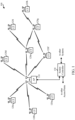
- a WLAN includes various devices which are the components that access the wireless network.
- access points access points
- STAs stations
- an AP serves as a hub or base station for the WLAN and an STA serves as a user of the WLAN.
- a STA may be a laptop computer, a personal digital assistant (PDA), a mobile phone, etc.
- PDA personal digital assistant
- an STA connects to an AP via a Wi-Fi (e.g., IEEE 802.11 protocol such as 802.11ah) compliant wireless link to obtain general connectivity to the Internet or to other wide area networks.
- Wi-Fi e.g., IEEE 802.11 protocol such as 802.11ah
- an STA may also be used as an AP.
- a wireless node implemented in accordance with the teachings herein may comprise an access point or an access terminal.
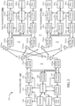
- a TX data processor 288 receives traffic data from a data source 286 and control data from a controller 280.
- the TX data processor 288 processes (e.g., encodes, interleaves, and modulates) the traffic data for the wireless communication device 120 based on the coding and modulation schemes associated with the rate selected for the wireless communication device 120 and provides a data symbol stream.
- a TX spatial processor 290 performs spatial processing on the data symbol stream and provides Nut,m transmit symbol streams for the Nut,m antennas.
- Each transmitter unit 254 receives and processes (e.g., converts to analog, amplifies, filters, and frequency upconverts) a respective transmit symbol stream to generate an uplink signal.
- Nut,m transmitter/receiver units 254 provide Nut,m uplink signals for transmission from Nut,m antennas 252, for example to transmit to the access point 110.
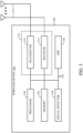
- the wireless communication device 302 may also include a signal detector 318 that may be used in an effort to detect and quantify the level of signals received by the transceiver 314.
- the signal detector 318 may detect such signals as total energy, energy per subcarrier per symbol, power spectral density and other signals.
- the wireless communication device 302 may also include a digital signal processor (DSP) 320 for use in processing signals.
- DSP digital signal processor
- Certain aspects of the present disclosure support transmitting data packets from multiple STAs to an AP.
- the data packets may be transmitted in a multi-user MIMO (MU-MIMO) system.
- the data packets may be transmitted in a multi-user-FDMA (MU-FDMA), multi-user OFDMA (MU-OFDMA) or similar Frequency Division Multiple Access (FDMA) system.
- MU-MIMO multi-user MIMO
- MU-OFDMA multi-user OFDMA
- FDMA Frequency Division Multiple Access
- uplink MU-MIMO, uplink OFDMA, or similar uplink FDMA system transmissions can be sent simultaneously from multiple STAs to an AP and may create efficiencies in wireless communication.
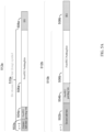
- FIG. 4 illustrates an exemplary data packet 400, in accordance with one embodiment.
- one or more of the wireless communication devices 120 may transmit data packet 400 to AP 110.
- AP 110 may transmit data packet 400 to one or more of the wireless communication devices 120.
- data packet 400 is transmitted over a plurality of symbols. The number of symbols used to transmit data packet 400 can vary greatly depending on the contents thereof.
- data packet 400 comprises legacy preamble 402, high efficiency (HE) preamble 404, and HE data 406 through 410.
- HE high efficiency
- data packet 400 may include data transmitted in accordance with an IEEE 802.11ax format.
- the amount of information transmitted in data packet 400 can be approximately four times more than the information transmitted in accordance with other protocols (e.g., 802.11a).
- multiple data packets 400 may be transmitted in series to a receiving device (e.g., wireless communication device 120 or AP 110).
- a SIFS Short Interframe Space
- a SIFS time period between packets may not be a sufficient amount of processing time for a device receiving the packet 400 to completely process the packet before a second packet arrived. This may especially be the case when the packet 400 has four times the information than, for example, an 802.11a packet. Accordingly, various systems and methods for providing the receiving device with additional processing time are described.
- FIGs. 5A-B illustrates various final symbols with signal extension (SE) of an exemplary data packet, in accordance with one embodiment.
- a transmitting device e.g., wireless communication device 120 or AP 110
- SIFS+the signaling extension (SE) time when the SE is added to the last symbol or within SIFS alone if SE is not added
- Useful bits may include, for example, data bits encoding user data included in the data packet, and, in some aspects, bits necessary to properly decode the data bits from the packet.
- useful bits may be a first type of bits, while other bits may be a second type of bits.
- useful bits may be bits associated with a first layer in a layered protocol architecture. For example, in some aspects using 802.11, the 802.11 protocol may utilize one or more bits in each packet for signaling purposes. Other bits in a packet may be provided by a higher layer, for example, an application layer. In some aspects, the bits provided by the higher layer, i.e. above the 802.11 layer, may be considered useful bits. These higher layer bits may be considered a first type of bits, while bits utilized for 802.11 signaling may be considered a second type of bits. In some aspects, useful bits may be utilized for encoding data bits received from a higher level protocol or application layer.
- the amount, length, or size of the SE can depend on how much information is remaining (also referred to as "excess") in the final symbol.
- four different sizes of SE may be used based on how much information is remaining in the final symbol.
- each size may correspond to a percentage (e.g., 25%, 50%, 75%, 100%), but may be represented by an integer (e.g., 1-4) or a two bit indication (e.g., 00, 01, 10, or 11).
- various cut-offs may be utilized (also referred to as "a,” the " a factor,” or the " a value”) by the transmitting and receiving devices.
- the a value may refer to a fraction of "useful bits" in the final symbol of the data transmission (e.g., an a value of 1 can indicate that the first quarter of bits convey information to the receiving device, and an a value of 2 can indicate that the first half of the bits convey information that may be used by the receiving device).
- a device transmitting this data may be able to determine the length of the excess information bits in the final symbol, and in turn, what value ' a ' to include in a packet, a priori, based on information about the entire transmission (e.g., data packet 400). Thereafter, a device receiving this data may be able to determine what a value to use based on information about the data (e.g., the length of the packet).
- Packet 512a includes excess information bits 502a remaining within the first quarter of the final symbol 510a of packet 512a.
- a transmitting device may add pre-FEC (frame-error checking) padding bits 504a up to the boundary corresponding to the first quarter (25%) of the symbol 510a.
- pre-FEC frame-error checking
- a receiving device may only process the bits untilthe end of pre-FEC padding bits 504a.
- bits included in the Post-FEC padding field 506a and the SE1 field 508a may be received but not processed by a device receiving the packet 512a.
- a transmitting device may add post-FEC padding bits 506a at the end of the symbol 510a, in some cases after pre-FEC padding bits, and may add SE 508a of a first length to the end of the packet 512a.
- a receiving device may use the time corresponding to the time it would normally require to process received bits, to instead of processing or decoding the post-FEC padding bits 506a and SE 508a, the device may process the other information received in the packet 512a. After a SIFS time period after the end of the symbol 510a and SE 508a have been transmitted, a transmitting device of packet 512a may transmit another data packet.
- the first length may be 4 ⁇ s
- the second length may be 8 ⁇ s
- the third length may be 12 ⁇ s
- the fourth length may be 16 ⁇ s.
- one or more of packets 512a-d may not include SE field 508a-d.
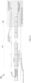
- FIG. 6 illustrates an exemplary transmission of a data packet 600 with SE, in accordance with one embodiment of the claimed invention.
- packet 600 comprises a legacy preamble and HE preamble 602, HE data 1-N transmitted over a plurality of symbols 604, and SE 606 appended to the end.
- Each of the individual symbols within 604 has a data symbol duration (not shown).
- a device receiving packet 600 may calculate the number of symbols required to receive the packet 600, based at least in part upon a transmission length.
- a transmission length of the packet 600 is provided in the legacy preamble or the HE preamble 602.
- a quantization of the transmission length may create ambiguities due to a "rounding error" ⁇ .
- a transmitting or receiving device may determine that an applied SE will cause processing inefficiencies based on the rounding error ⁇ .
- a transmitting or receiving device of packet 600 may determine that the length of the applied SE 606 plus a length of the rounding error ⁇ is greater than the data symbol duration discussed above.
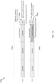
- FIG. 7A illustrates an exemplary transmission 700a of data packets 705a-b with SE in a multi-user scenario, in accordance with one embodiment.
- an AP 110 may transmit packets to more than one wireless communication device 120 at a time.
- the data within each of the packets transmitted to each wireless communication device 120 may vary.
- information e.g., padding bits
- the packet 705a received by a first station STA1 may comprise SE 706a based upon the processing needs of a second station STA2.
- the first station STA1 may ignore the SE 706a.
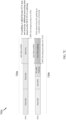
- FIG. 7B illustrates an exemplary transmission 700b of data packets 710a-b with SE in a multi-user scenario, in accordance with one embodiment.
- a signaling extension (SE) 711a-b may be added to the end of a data transmission (e.g., after the last symbol of the last data packet).
- a receiving device may receive communications in accordance with a modulation and coding scheme (MCS).
- MCS modulation and coding scheme
- the first station STA1 in FIG. 7B may receive communications in accordance with MCS2 while the second station STA2 may receive communications in accordance with MCS7.
- MCS modulation and coding scheme
- multi-user transmissions may utilize SEs that are specialized for each different MCS of the receiving devices.
- a receiving device may signal its MCS capabilities (e.g., thresholds) upon association. These thresholds may indicate, based on the MCS a receiving device is using, whether the receiving device is capable of receiving a communication without additional processing time, and otherwise, if additional processing time is required, how much.
- MCS capabilities e.g., thresholds
- a wireless communication device 120 may use eight bits to signal two thresholds to an AP 110. The first four of the bits can correspond to the first MCS threshold, and the latter four bits can correspond to the second MCS threshold.
- Table 1 One embodiment of these thresholds is provided below in Table 1.
- wireless communication device 120 may signal "00110110" during association to signal that it requires 0 ⁇ s of processing time for MCS0 through MCS3, 8 ⁇ s of processing time for MCS4 through MCS7, and 16 ⁇ s of processing time for MCS8 and up.
- FIG. 7C illustrates another exemplary transmission 700c of data packets 720a-b with SE in a multi-user scenario, in accordance with one embodiment.
- the entire last data symbol may contain useful bits for the first station STA1
- the first station STA1 may not need any additional processing time, based on the MCS the first station STA1 is utilizing to receive its portion of the transmission 700c.
- the second station STA2 may have indicated that it requires 16 ⁇ s of additional processing time based on the MCS utilized, and the last data symbol for the second station STA2 may not contain any useful bits.
- the transmitting device may pad the final data symbol of the transmission for the second station STA2 so that the second station STA2 may still be afforded the 16 ⁇ s it needs.
- a signaling extension of 16us may be added.
- FIG. 8 is a flow chart of an aspect of an exemplary process 800 of wireless communication.
- Process 800 may also be considered a method of wireless communication.
- Process 800 may be performed, in some aspects, by the device 302 discussed above with respect to FIG. 3 .
- instructions stored in the memory 306 may configure the processor 304 to perform one or more of the functions discussed above with respect to process 800.
- process 800 may be utilized to transmit data with SE from an AP 110 to a wireless communication device 120.
- the content of the data to be transmitted and the wireless communication devices 120 to which the data is to be transmitted may be known.
- Block 805 of process 800 determines a corresponding a value ( a u ) and a corresponding number of symbols required (N sym,u ) to transmit a corresponding plurality of data bits to each STA. This determination may be made, at least in part upon a first initial packet size of the transmission including the data bits for each STA. Further, the a value may be one of 1, 2, 3, or 4, and may correspond to one of the four boundaries described above. In some aspects, the a value for each STA may be based on a corresponding fraction of useful bits in a final symbol of the symbols required to transmit the corresponding plurality of data bits to the corresponding STA. In some aspects, the fraction of useful bits may be a fraction of bits encoding the corresponding plurality of data bits.
- a maximum number of symbols (N sym,init ) and a maximum fraction of bits ( a value ( a init )) for the plurality of data bits is determined based on the determined number of symbols and the a values for all STAs.
- the maximum fraction of bits may be a maximum fraction of useful bits.
- the maximum number of symbols may be determined separately from the maximum a value.
- the maximum a value is associated with an STA having the maximum number of symbols to be transmitted. This determination may be made according to the following formulas.
- a init a k -> select a init as the a value corresponding to the user that has the maximum number of symbols to be transmitted.
- pre-FEC padding is applied for the STAs until the data fills the total number of the maximum number of symbols ( N sym , init ) up until a boundary identified by the maximum a value ( a init ).
- the pre-FEC padding is applied by the media access control (MAC) layer and is considered to be part of the information bits to be decoded by the STA.
- MAC media access control
- Block 820 determines whether any of the wireless communication devices (STAs) require an additional symbol, such as an additional short symbol.
- a STA may require an additional short symbol due to an encoding method of a data packet transmitted to the STA.
- LDPC low density parity check
- a short symbol corresponds to one fourth of the length of the symbol.
- some aspects of block 820 may including altering one or more of the fraction of useful bits or the number of symbols required if any one of the plurality of wireless communication devices requires an additional short system. For example, the maximum a value and the maximum number of symbols required may be altered.
- Block 825 determines, for each of the plurality of wireless communication devices, a corresponding signaling extension length of extension bits (SE) for each STA ( PE u ) based at least in part on the corresponding fraction of useful bits ( a value) and a modulation and coding scheme (MCS) capability of each of the plurality of wireless communication devices.
- a wireless communications device 120 may have indicated that it requires 0 ⁇ s of processing time for MCS0 through MCS3, 8 ⁇ s of processing time for MCS4 through MCS7, and 16 ⁇ s of processing time for MCS8 and up. Accordingly, AP 110 may determine what MCS the device is currently using, and compare this to the thresholds set during association.
- the AP 110 can determine that a 8 ⁇ s SE is necessary for this device. In some aspects, AP 110 may determine that some or all of this additional processing time is already available to the wireless communications device 120, based at least in part on the a value. For example, if the a value is 2, then the wireless communications device 120 may have 8 ⁇ s free after the end of the last symbol to process the received data. However, if the a value is 3, for example, the wireless communications device 120 may only have 4 ⁇ s of time to process the data after the end of the symbol. Accordingly, in some aspects, AP 110 may determine that the wireless communications device 120 requires a SE of 4 ⁇ s to properly process the transmission.
- the AP 110 may determine that the wireless communications device 120 requires a SE of 12 ⁇ s to be added to the end of the transmission. AP 110 may utilize the a value of the particular wireless communications device 120, or may utilize the maximum a value for this purpose. AP 110 may perform this process for each of the wireless communications devices 120 receiving data in order to determine the maximum PE.
- process 800 entails applying the maximum SE to the frame for all STAs. At this point, the transmission length for all of the STAs can be the same.
- Block 830 may include generating a plurality of data packets, each data packet including the corresponding data bits and extension bits of the corresponding signaling extension length after the final symbol for each of the plurality of data bits.
- the plurality of data packets are generated to include the padding bits after the data bits discussed above.
- the padding bits may be included in the data packet until a bit location indicated by the maximum fraction of useful bits in the maximum number of symbols, based at least in part upon a length of the corresponding data bits.
- Block 835 transmits the plurality of data packets to each of the plurality of wireless communication devices respectively.
- Each of the plurality of data packets may include one or more of the corresponding indication of the a value (e.g. or a corresponding first indication of the fraction of useful bits), SE disambiguation indication as described above with reference to FIG. 6 , and a second indication of whether an additional short symbol indication was added or is contained in the data packet based on the requirements of at least one of the wireless communications devices 120.
- one or more of the a values may be indicated by two bits, the SE disambiguation indication may be one bit, and the additional short symbol indication may be one bit (for a total of four bits). In one aspect, these bits may be provided in the header of the packet being transmitted, such as in an L-SIG or an HE-SIG of the packet header. It should be appreciated that additional functions may be present in process 800, and that not all of the functions discussed above with respect to process 800 may be necessary. In some aspects, the transmitter 310 may be configured to perform the transmission described with respect to block 835.
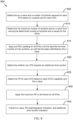
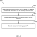
- FIG. 9 is a flow chart of an aspect of an exemplary process 900 of wireless communication.
- process 900 may be utilized by a wireless communications device 120 to receive data with SE from an AP 110.
- the process 900 may be performed by the device 302, discussed above with respect to FIG. 3 .
- instructions stored in the memory 306 may configure the processor 304 to perform one or more of the functions discussed below with respect to process 900.
- Block 905 determines a number of symbols and an applied SE based on packet length information and a SE disambiguation indication. As described above, this information may be indicated in a header of a packet that a device, performing process 900, such as the device 120, receives. The packet may be received, in some aspects, by the receiver 312.
- a data symbol is decoded utilizing the applied PE.
- the data symbol may be decoded from the received packet discussed above based on the PDPC decoding process, and the wireless communication device 120 may utilize the processing time provided by SE as a buffer to complete processing of the data transmission.
- Block 915 may include processing the decoded data symbol.
- the decoded data symbol may be utilized to form byte values of the received packet.
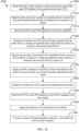
- FIG. 10 is a flow chart of an aspect of an exemplary process 1000 of wireless communication.
- process 1000 may be utilized to transmit data with SE from an AP 110 to a wireless communication device 120.
- Process 1000 may be similar to process 800 of FIG. 8 , but may provide additional or alternative processing efficiencies.
- the content of the data to be transmitted and the wireless communication devices 120 to which the data is to be transmitted may be known.
- process 1000 first involves determining the a value and the number of symbols required for each STA based on the packet size for each STA. This determination may be made, at least in part upon the packet size of the transmission for each STA. Further, the a value may be one of 1, 2, 3, or 4, and may correspond to one of the four boundaries described above.
- process 1000 entails determining the maximum number of symbols and an a value from among the determined number of symbols and a values for all STAs.
- the maximum number of symbols may be determined separately from the maximum a value.
- the maximum a value corresponds to the a value associated with the STA that has the maximum number of symbols to be transmitted.
- process 1000 entails determining SE for each STA based on the device capability (e.g., 0 ⁇ s, 8 ⁇ s, or 16 ⁇ s based on the current MCS as compare to the thresholds indicated by the wireless communications device 120 at association).
- process 1000 entails determining whether any STA has a SE that is greater than all other STAs, a number of symbols that is less than the maximum, and an a value that is less than 4.
- This STA is referred to below as an "identified" STA.
- AP 110 may utilize the following formulas: proc _ extn u > max ⁇ k k ⁇ u proc _ extn k N sym , u ⁇ N sym , init a u ⁇ 4
- process 1000 entails applying pre-FEC padding for all STAs until the data fills the total number of the maximum number of symbols ( N sym , init ), up until the boundary identified by the maximum a value ( a init ). At this point, the length of each of the data packets including the padding can be the same. However, for identified STAs, a different padding may be used. In some aspects, pre-FEC padding is applied until the boundary indicated by the STA's own a value ( a u ), and post-FEC padding is applied for the last symbol.
- process 1000 entails determining whether any STA requires an additional short symbol.
- a device may require an additional short symbol due to LDPC encoding.
- a short symbol corresponds to one fourth of the length of the symbol.
- the maximum a value and the maximum number of symbols required may be altered. For example, if the maximum a value is less than 4, then the value of 1 is added thereto. However, if the maximum a value is 4, then the value thereof is changed to 1, and the value of 1 is added to the maximum number of symbols required.
- the LDPC encoding process is repeated taking the extra symbol and the new a value into account.
- Pre-FEC padding is applied to each STA in accordance with the new a value. For some STAs (identified earlier as satisfying the conditions) the number of symbols is increased but the a value does not change.
- process 1000 entails determining SE for each STA based on each STA's capability and the a value, similar to process 800 described above with reference to FIG. 8 .
- AP 110 may utilize the a value of the particular wireless communications device 120, or may utilize the maximum a value for this purpose. AP 110 may perform this process for each of the wireless communications devices 120 receiving data in order to determine the maximum PE. However, for the identified STAs, a different determination may be made. In one aspect, the entire last symbol may be used as the SE for the device, and therefore no additional SE may be required. Therefore, AP 110 may rule the identified STAs out in making the determination of the maximum SE to apply.
- process 1000 entails applying the maximum SE to the frame for all STAs. At this point, the transmission length for all of the STAs can be the same.
- process 1000 entails transmitting the a value, a SE disambiguation indication as described above with reference to FIG. 6 , and additional short symbol indication that may indicate whether an additional short symbol was added based on the requirements of at least one of the wireless communications devices 120.
- the a value may be indicated by two bits
- the SE disambiguation indication may be one bit
- the additional short symbol indication may be one bit (for a total of four bits).
- these bits may be provided in the header of the packet being transmitter, such as in an L-SIG or an HE-SIG of the packet header. It should be appreciated that additional steps may be present in process 1000, and that not all of the steps of process 1000 may be necessary.
- FIG. 11 is a flow chart of an aspect of an exemplary process 1100 of wireless communication.
- process 1100 discussed below with respect to FIG. 11 may be performed by the device 302.
- instructions in the memory 306 may configure the processor 304 to perform one or more of the functions discussed below with respect to process 1100.
- process 1100 may be utilized by a wireless communications device 120 to receive data with SE from an AP 110.
- Block 1105 determines a number of symbols and an applied SE based on packet length information and a SE disambiguation indication. As described above, this information may be indicated in the header of a packet received by a device performing process 1100. For example, this information may be in a packet that the wireless communications device 120 is receiving.
- Block 1110 determines whether to adjust the determined a value and the number of symbols based on a device capability. For example, in one aspect, a receiving device may determine whether the applied SE is less than an amount of SE required for the receiving device based on the a value provided and a device capability indicated at association. Alternatively, an indication may be provided to each of the wireless communication devices 120 that satisfy this criteria, and each of the receiving devices would check this indication to determine whether it is one of the identified devices.
- the devices may decrease or decrement the number of symbols by a value of 1, and if the additional short symbol indication is set to the value of 1, then set a equal to the value of 4, but if the additional short symbol indication is set to the value of 0, then set a equal to the value of 3.
- Block 1120 decodes the data symbol utilizing the applied PE.
- the data symbol may be decoded based on the PDPC decoding process, and the wireless communication device 120 may utilize the processing time provided by SE as a buffer to complete processing of the data transmission.
- N CBPS bandwidth of coded bits per short symbol
- N DBPS number of data bits in a short symbol
- N DBPS,Short /N ES number of binary convolutional codes (BCC) encoders required
- N SD,short should be such that it is one fourth of that of N SD,long .
- values identified in Table 2 below may be used.
- each boundary indicated by the a values 1-4 will be 6 tones apart.
- a 1
- a 2
- N SD,short When the value of N SD,short is not exactly one fourth of N SD in Table 1, the first three boundaries indicated by the a values of 1, 2, and 3, will be N SD tones apart, and the remaining a value of 4 will correspond to the remaining balance of tones.
- N SD is listed as 120 for the BW of 40MHz, 114 tones may be alternatively used. However, this alternative choice may not satisfy 1024QAM with a code rate of 7/8.
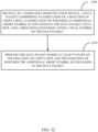
- FIG. 12 is a flowchart of a method of receiving a data packet of the format disclosed here.
- process 1200 may be performed by the wireless device 302.
- the receiver 312 may be configured to receive the packet and the processor 304 may be configured to decode the packet as described above.
- the reception of the packet may be controlled by the processor 304.
- the processor 304 may indicate to the receiver that it should configure itself to receive a packet, and then may copy data from the receiver 312 to the memory 306 after the packet has been received.
- a data packet is received.
- the data packet includes an indication of a fraction of useful data bits, and the data bits.
- the data packet may include an indication of whether an additional short symbol is contained in the data packet, and/or a signaling extension after a final symbol of the data packet.
- processing the data packet may include decoding the data packet based on one or more of the indications in the data packet.
- the data packet may be processed based on the indication of whether the additional short symbol is contained in the data packet.
- the data bits may be extracted from the packet based on the useful data bits indication.
- the indicated useful bits may be copied to a buffer and processed based on a predetermined packet format.
- a frame check sequence may be extracted from the end of the packet based on the number of useful bits indication. The frame check sequence may then be used to verify an integrity of the packet.
- an apparatus for wireless communication may perform any of the processes 800-1100 described in FIGs. 8-11 .
- the apparatus for wireless communication is similar to the wireless communication device 302 of FIG. 3 .
- the apparatus comprises means for generating a first message requesting channel state information from one or more wireless communication devices.
- the generated first message may comprise a header and a payload.
- the header of the first message may comprise a plurality of fields of a first field type which are useable to determine the requested channel state information, and the payload of the first message may comprise channel state information parameters.
- the apparatus may further comprise means for transmitting the first message to the one or more wireless communication devices.
- a phrase referring to "at least one of" a list of items refers to any combination of those items, including single members.
- “at least one of: A, B or C” is intended to cover A or B or C or A and B or A and C or B and C or A, B and C or 2A or 2B or 2C and so on.
- any suitable means capable of performing the operations such as various hardware and/or software component(s), circuits, and/or module(s).
- any operations illustrated in the Figures may be performed by corresponding functional means capable of performing the operations.
- an interface may refer to hardware or software configured to connect two or more devices together.
- an interface may be a part of a processor or a bus and may be configured to allow communication of information or data between the devices.
- the interface may be integrated into a chip or other device.
- an interface may comprise a receiver configured to receive information or communications from a device at another device.
- the interface e.g., of a processor or a bus
- an interface may comprise a transmitter configured to transmit or communicate information or data to another device.
- the interface may transmit information or data or may prepare information or data for outputting for transmission (e.g., via a bus).
- DSP digital signal processor
- ASIC application specific integrated circuit
- FPGA field programmable gate array
- PLD programmable logic device
- a general purpose processor may be a microprocessor, but in the alternative, the processor may be any commercially available processor, controller, microcontroller or state machine.
- a processor may also be implemented as a combination of computing devices, e.g., a combination of a DSP and a microprocessor, a plurality of microprocessors, one or more microprocessors in conjunction with a DSP core, or any other such configuration.
- the functions described may be implemented in hardware, software, firmware, or any combination thereof. If implemented in software, the functions may be stored on or transmitted over as one or more instructions or code on a computer-readable medium.
- Computer-readable media includes both computer storage media and communication media including any medium that facilitates transfer of a computer program from one place to another.
- a storage media may be any available media that can be accessed by a computer.
- such computer-readable media can comprise RAM, ROM, EEPROM, CD-ROM or other optical disk storage, magnetic disk storage or other magnetic storage devices, or any other medium that can be used to carry or store desired program code in the form of instructions or data structures and that can be accessed by a computer.
- any connection is properly termed a computer-readable medium.
- the software is transmitted from a website, server, or other remote source using a coaxial cable, fiber optic cable, twisted pair, digital subscriber line (DSL), or wireless technologies such as infrared, radio, and microwave
- the coaxial cable, fiber optic cable, twisted pair, DSL, or wireless technologies such as infrared, radio, and microwave are included in the definition of medium.
- Disk and disc includes compact disc (CD), laser disc, optical disc, digital versatile disc (DVD), floppy disk and Blu-ray disc where disks usually reproduce data magnetically, while discs reproduce data optically with lasers.
- computer readable medium may comprise non-transitory computer readable medium (e.g., tangible media).
- computer readable medium may comprise transitory computer readable medium (e.g., a signal). Combinations of the above should also be included within the scope of computer-readable media.
- the methods disclosed herein comprise one or more steps or actions for achieving the described method.
- the method steps and/or actions may be interchanged with one another without departing from the scope of the claims.
- the order and/or use of specific steps and/or actions may be modified without departing from the scope of the claims.
- modules and/or other appropriate means for performing the methods and techniques described herein can be downloaded and/or otherwise obtained by a user terminal and/or base station as applicable.
- a user terminal and/or base station can be coupled to a server to facilitate the transfer of means for performing the methods described herein.
- various methods described herein can be provided via storage means (e.g., RAM, ROM, a physical storage medium such as a compact disc (CD) or floppy disk, etc.), such that a user terminal and/or base station can obtain the various methods upon coupling or providing the storage means to the device.
- storage means e.g., RAM, ROM, a physical storage medium such as a compact disc (CD) or floppy disk, etc.
- CD compact disc
- floppy disk etc.
- any other suitable technique for providing the methods and techniques described herein to a device can be utilized.
Landscapes
- Engineering & Computer Science (AREA)
- Signal Processing (AREA)
- Computer Networks & Wireless Communication (AREA)
- Quality & Reliability (AREA)
- Mobile Radio Communication Systems (AREA)
- Error Detection And Correction (AREA)
- Time-Division Multiplex Systems (AREA)
- Detection And Prevention Of Errors In Transmission (AREA)
Priority Applications (1)
| Application Number | Priority Date | Filing Date | Title |
|---|---|---|---|
| EP25154007.6A EP4521667A3 (en) | 2015-07-06 | 2016-06-28 | Methods and apparatus for extended receiver processing time |
Applications Claiming Priority (3)
| Application Number | Priority Date | Filing Date | Title |
|---|---|---|---|
| US201562189170P | 2015-07-06 | 2015-07-06 | |
| US15/194,348 US10148326B2 (en) | 2015-07-06 | 2016-06-27 | Methods and apparatus for extended receiver processing time |
| PCT/US2016/039819 WO2017007638A1 (en) | 2015-07-06 | 2016-06-28 | Methods and apparatus for extended receiver processing time |
Related Child Applications (2)
| Application Number | Title | Priority Date | Filing Date |
|---|---|---|---|
| EP25154007.6A Division-Into EP4521667A3 (en) | 2015-07-06 | 2016-06-28 | Methods and apparatus for extended receiver processing time |
| EP25154007.6A Division EP4521667A3 (en) | 2015-07-06 | 2016-06-28 | Methods and apparatus for extended receiver processing time |
Publications (3)
| Publication Number | Publication Date |
|---|---|
| EP3320634A1 EP3320634A1 (en) | 2018-05-16 |
| EP3320634B1 true EP3320634B1 (en) | 2025-04-09 |
| EP3320634C0 EP3320634C0 (en) | 2025-04-09 |
Family
ID=56550966
Family Applications (2)
| Application Number | Title | Priority Date | Filing Date |
|---|---|---|---|
| EP16744590.7A Active EP3320634B1 (en) | 2015-07-06 | 2016-06-28 | Methods and apparatus for extended receiver processing time |
| EP25154007.6A Pending EP4521667A3 (en) | 2015-07-06 | 2016-06-28 | Methods and apparatus for extended receiver processing time |
Family Applications After (1)
| Application Number | Title | Priority Date | Filing Date |
|---|---|---|---|
| EP25154007.6A Pending EP4521667A3 (en) | 2015-07-06 | 2016-06-28 | Methods and apparatus for extended receiver processing time |
Country Status (18)
Families Citing this family (6)
| Publication number | Priority date | Publication date | Assignee | Title |
|---|---|---|---|---|
| EP3629537B1 (en) * | 2016-01-14 | 2022-01-05 | Panasonic Intellectual Property Management Co., Ltd. | Method and system for padding and packet extension for downlink multiuser transmission |
| EP3476138B1 (en) * | 2016-08-03 | 2024-10-02 | Lenovo Innovations Limited (Hong Kong) | Device-to-device transmission |
| US11082156B2 (en) * | 2018-10-30 | 2021-08-03 | Nxp Usa, Inc. | Method and apparatus for generating a physical layer (PHY) data unit for hybrid automatic repeat request (HARQ) |
| US12464041B2 (en) | 2019-02-13 | 2025-11-04 | Telefonaktiebolaget Lm Ericsson (Publ) | Industrial automation with 5G and beyond |
| CN112073103B (zh) * | 2019-06-10 | 2022-01-11 | 上海诺基亚贝尔股份有限公司 | 在mu-mimo系统中进行波束成形的方法和装置 |
| CN114760019A (zh) * | 2021-01-11 | 2022-07-15 | 华为技术有限公司 | 一种名义包填充值的指示方法、确定方法及通信装置 |
Family Cites Families (13)
| Publication number | Priority date | Publication date | Assignee | Title |
|---|---|---|---|---|
| EP1379001A3 (en) * | 2002-07-03 | 2004-03-10 | Hughes Electronics Corporation | Method and system for decoding low density parity check (LDPC) codes |
| DE60317682T2 (de) * | 2002-08-14 | 2008-10-30 | Koninklijke Philips Electronics N.V. | Auswahl zwischen zwei verschiedenen codierungsverfahren und entsprechenden modulationsverfahren gemäss der zulässigen übertragungsverzögerung der daten |
| GB0326936D0 (en) * | 2003-11-19 | 2003-12-24 | Samsung Electronics Co Ltd | Mobile communications |
| US7580388B2 (en) * | 2004-06-01 | 2009-08-25 | Lg Electronics Inc. | Method and apparatus for providing enhanced messages on common control channel in wireless communication system |
| US20100199142A1 (en) * | 2007-04-13 | 2010-08-05 | University College Dublin, National University Of Ireland | Encoding scheme, and a decoding scheme using a series of ldpc codes based on finite inversive spaces |
| JP2008270863A (ja) | 2007-04-16 | 2008-11-06 | Matsushita Electric Ind Co Ltd | 無線受信装置、無線送信装置および無線通信システム |
| JP5646624B2 (ja) * | 2009-07-29 | 2014-12-24 | マーベル ワールド トレード リミテッド | 通信チャネルを介して送信するための物理層(phy)データユニットを生成する方法、および物理層装置 |
| BR112012010467B1 (pt) * | 2009-11-04 | 2021-09-08 | Electronics And Telecommunications Research Institute | Equipamento de transmissão de blocos de dados em sistema de comunicação sem fio e método para rede local sem fio |
| CN101902301B (zh) * | 2010-08-12 | 2018-11-20 | 中兴通讯股份有限公司 | 上行控制信令发送、上行解调参考信号的承载方法及装置 |
| US8824371B2 (en) * | 2011-05-13 | 2014-09-02 | Qualcomm Incorporated | Systems and methods for wireless communication of packets having a plurality of formats |
| US8761234B2 (en) * | 2011-10-25 | 2014-06-24 | Qualcomm Incorporated | Rate selection for frames in wireless devices |
| US9743399B2 (en) * | 2012-09-07 | 2017-08-22 | Intel Corporation | Methods and arrangements to signal short interframe spaces |
| US20160374017A1 (en) * | 2015-06-18 | 2016-12-22 | Intel IP Corporation | Systems and methods for determining device-specific signal extension durations |
-
2016
- 2016-06-27 US US15/194,348 patent/US10148326B2/en active Active
- 2016-06-28 AU AU2016290797A patent/AU2016290797B2/en active Active
- 2016-06-28 EP EP16744590.7A patent/EP3320634B1/en active Active
- 2016-06-28 CN CN201680039607.8A patent/CN107710658B/zh active Active
- 2016-06-28 JP JP2018500286A patent/JP6633177B2/ja active Active
- 2016-06-28 NZ NZ737344A patent/NZ737344A/en unknown
- 2016-06-28 KR KR1020187000323A patent/KR102017869B1/ko active Active
- 2016-06-28 MY MYPI2017704302A patent/MY184058A/en unknown
- 2016-06-28 WO PCT/US2016/039819 patent/WO2017007638A1/en not_active Ceased
- 2016-06-28 EP EP25154007.6A patent/EP4521667A3/en active Pending
- 2016-06-28 CA CA2986614A patent/CA2986614C/en active Active
- 2016-06-28 RU RU2017146393A patent/RU2697699C2/ru active
- 2016-06-28 MX MX2017016052A patent/MX369872B/es active IP Right Grant
- 2016-06-30 TW TW105120662A patent/TWI676377B/zh active
-
2017
- 2017-11-12 IL IL255595A patent/IL255595B/en active IP Right Grant
-
2018
- 2018-01-02 CL CL2018000001A patent/CL2018000001A1/es unknown
- 2018-01-02 SA SA518390679A patent/SA518390679B1/ar unknown
- 2018-01-05 ZA ZA2018/00093A patent/ZA201800093B/en unknown
- 2018-01-05 CO CONC2018/0000079A patent/CO2018000079A2/es unknown
Also Published As
Similar Documents
| Publication | Publication Date | Title |
|---|---|---|
| US10484159B2 (en) | Methods and systems for acknowledgment configuration | |
| US9948367B2 (en) | Methods and apparatus for acknowledging multiple user uplink transmissions | |
| US10856281B2 (en) | Methods and systems for multi user uplink compatibility with legacy devices | |
| AU2016290797B2 (en) | Methods and apparatus for extended receiver processing time | |
| CA2926091A1 (en) | Methods and apparatus for channel state information feedback | |
| EP3281323B1 (en) | Wi-fi frames including frame extensions | |
| AU2015364393A1 (en) | Transmission techniques for enabling an immediate response | |
| US20180367242A1 (en) | He-sig-b mcs value adaptation for multi-user transmission | |
| EP3213451A1 (en) | Control channel on plcp service data unit (psdu) tones | |
| HK1245528B (en) | Methods and apparatus for extended receiver processing time | |
| BR112018000219B1 (pt) | Métodos e aparelhos para tempo de processamento de recepção estendido | |
| HK1220822A1 (zh) | 用於多用戶上行鏈路無線傳輸的確收的方法和裝置 |
Legal Events
| Date | Code | Title | Description |
|---|---|---|---|
| STAA | Information on the status of an ep patent application or granted ep patent |
Free format text: STATUS: THE INTERNATIONAL PUBLICATION HAS BEEN MADE |
|
| PUAI | Public reference made under article 153(3) epc to a published international application that has entered the european phase |
Free format text: ORIGINAL CODE: 0009012 |
|
| STAA | Information on the status of an ep patent application or granted ep patent |
Free format text: STATUS: REQUEST FOR EXAMINATION WAS MADE |
|
| 17P | Request for examination filed |
Effective date: 20180105 |
|
| AK | Designated contracting states |
Kind code of ref document: A1 Designated state(s): AL AT BE BG CH CY CZ DE DK EE ES FI FR GB GR HR HU IE IS IT LI LT LU LV MC MK MT NL NO PL PT RO RS SE SI SK SM TR |
|
| AX | Request for extension of the european patent |
Extension state: BA ME |
|
| DAV | Request for validation of the european patent (deleted) | ||
| DAX | Request for extension of the european patent (deleted) | ||
| STAA | Information on the status of an ep patent application or granted ep patent |
Free format text: STATUS: EXAMINATION IS IN PROGRESS |
|
| 17Q | First examination report despatched |
Effective date: 20210415 |
|
| GRAP | Despatch of communication of intention to grant a patent |
Free format text: ORIGINAL CODE: EPIDOSNIGR1 |
|
| STAA | Information on the status of an ep patent application or granted ep patent |
Free format text: STATUS: GRANT OF PATENT IS INTENDED |
|
| INTG | Intention to grant announced |
Effective date: 20241128 |
|
| GRAS | Grant fee paid |
Free format text: ORIGINAL CODE: EPIDOSNIGR3 |
|
| GRAA | (expected) grant |
Free format text: ORIGINAL CODE: 0009210 |
|
| STAA | Information on the status of an ep patent application or granted ep patent |
Free format text: STATUS: THE PATENT HAS BEEN GRANTED |
|
| AK | Designated contracting states |
Kind code of ref document: B1 Designated state(s): AL AT BE BG CH CY CZ DE DK EE ES FI FR GB GR HR HU IE IS IT LI LT LU LV MC MK MT NL NO PL PT RO RS SE SI SK SM TR |
|
| REG | Reference to a national code |
Ref country code: GB Ref legal event code: FG4D |
|
| REG | Reference to a national code |
Ref country code: CH Ref legal event code: EP |
|
| REG | Reference to a national code |
Ref country code: DE Ref legal event code: R096 Ref document number: 602016091840 Country of ref document: DE |
|
| REG | Reference to a national code |
Ref country code: IE Ref legal event code: FG4D |
|
| U01 | Request for unitary effect filed |
Effective date: 20250417 |
|
| U07 | Unitary effect registered |
Designated state(s): AT BE BG DE DK EE FI FR IT LT LU LV MT NL PT RO SE SI Effective date: 20250424 |
|
| U20 | Renewal fee for the european patent with unitary effect paid |
Year of fee payment: 10 Effective date: 20250625 |
|
| PG25 | Lapsed in a contracting state [announced via postgrant information from national office to epo] |
Ref country code: ES Free format text: LAPSE BECAUSE OF FAILURE TO SUBMIT A TRANSLATION OF THE DESCRIPTION OR TO PAY THE FEE WITHIN THE PRESCRIBED TIME-LIMIT Effective date: 20250409 |
|
| PG25 | Lapsed in a contracting state [announced via postgrant information from national office to epo] |
Ref country code: NO Free format text: LAPSE BECAUSE OF FAILURE TO SUBMIT A TRANSLATION OF THE DESCRIPTION OR TO PAY THE FEE WITHIN THE PRESCRIBED TIME-LIMIT Effective date: 20250709 Ref country code: GR Free format text: LAPSE BECAUSE OF FAILURE TO SUBMIT A TRANSLATION OF THE DESCRIPTION OR TO PAY THE FEE WITHIN THE PRESCRIBED TIME-LIMIT Effective date: 20250710 |
|
| PG25 | Lapsed in a contracting state [announced via postgrant information from national office to epo] |
Ref country code: PL Free format text: LAPSE BECAUSE OF FAILURE TO SUBMIT A TRANSLATION OF THE DESCRIPTION OR TO PAY THE FEE WITHIN THE PRESCRIBED TIME-LIMIT Effective date: 20250409 |
|
| PG25 | Lapsed in a contracting state [announced via postgrant information from national office to epo] |
Ref country code: HR Free format text: LAPSE BECAUSE OF FAILURE TO SUBMIT A TRANSLATION OF THE DESCRIPTION OR TO PAY THE FEE WITHIN THE PRESCRIBED TIME-LIMIT Effective date: 20250409 |
|
| PG25 | Lapsed in a contracting state [announced via postgrant information from national office to epo] |
Ref country code: RS Free format text: LAPSE BECAUSE OF FAILURE TO SUBMIT A TRANSLATION OF THE DESCRIPTION OR TO PAY THE FEE WITHIN THE PRESCRIBED TIME-LIMIT Effective date: 20250709 |
|
| PG25 | Lapsed in a contracting state [announced via postgrant information from national office to epo] |
Ref country code: IS Free format text: LAPSE BECAUSE OF FAILURE TO SUBMIT A TRANSLATION OF THE DESCRIPTION OR TO PAY THE FEE WITHIN THE PRESCRIBED TIME-LIMIT Effective date: 20250809 |
|
| PG25 | Lapsed in a contracting state [announced via postgrant information from national office to epo] |
Ref country code: SM Free format text: LAPSE BECAUSE OF FAILURE TO SUBMIT A TRANSLATION OF THE DESCRIPTION OR TO PAY THE FEE WITHIN THE PRESCRIBED TIME-LIMIT Effective date: 20250409 |
|
| PG25 | Lapsed in a contracting state [announced via postgrant information from national office to epo] |
Ref country code: CZ Free format text: LAPSE BECAUSE OF FAILURE TO SUBMIT A TRANSLATION OF THE DESCRIPTION OR TO PAY THE FEE WITHIN THE PRESCRIBED TIME-LIMIT Effective date: 20250409 |
|
| PG25 | Lapsed in a contracting state [announced via postgrant information from national office to epo] |
Ref country code: SK Free format text: LAPSE BECAUSE OF FAILURE TO SUBMIT A TRANSLATION OF THE DESCRIPTION OR TO PAY THE FEE WITHIN THE PRESCRIBED TIME-LIMIT Effective date: 20250409 |
|
| REG | Reference to a national code |
Ref country code: CH Ref legal event code: H13 Free format text: ST27 STATUS EVENT CODE: U-0-0-H10-H13 (AS PROVIDED BY THE NATIONAL OFFICE) Effective date: 20260127 |
|
| PG25 | Lapsed in a contracting state [announced via postgrant information from national office to epo] |
Ref country code: MC Free format text: LAPSE BECAUSE OF FAILURE TO SUBMIT A TRANSLATION OF THE DESCRIPTION OR TO PAY THE FEE WITHIN THE PRESCRIBED TIME-LIMIT Effective date: 20250409 |
|
| PLBE | No opposition filed within time limit |
Free format text: ORIGINAL CODE: 0009261 |
|
| STAA | Information on the status of an ep patent application or granted ep patent |
Free format text: STATUS: NO OPPOSITION FILED WITHIN TIME LIMIT |
|
| REG | Reference to a national code |
Ref country code: CH Ref legal event code: L10 Free format text: ST27 STATUS EVENT CODE: U-0-0-L10-L00 (AS PROVIDED BY THE NATIONAL OFFICE) Effective date: 20260218 |
|
| 26N | No opposition filed |
Effective date: 20260112 |
|
| PG25 | Lapsed in a contracting state [announced via postgrant information from national office to epo] |
Ref country code: CH Free format text: LAPSE BECAUSE OF NON-PAYMENT OF DUE FEES Effective date: 20250630 |
|
| U20 | Renewal fee for the european patent with unitary effect paid |
Year of fee payment: 11 Effective date: 20260513 |
|
| PGFP | Annual fee paid to national office [announced via postgrant information from national office to epo] |
Ref country code: GB Payment date: 20260518 Year of fee payment: 11 |
|
| PGFP | Annual fee paid to national office [announced via postgrant information from national office to epo] |
Ref country code: IE Payment date: 20260511 Year of fee payment: 11 |
|
| PG25 | Lapsed in a contracting state [announced via postgrant information from national office to epo] |
Ref country code: CY Free format text: LAPSE BECAUSE OF FAILURE TO SUBMIT A TRANSLATION OF THE DESCRIPTION OR TO PAY THE FEE WITHIN THE PRESCRIBED TIME-LIMIT Effective date: 20250409 |