EP3320599B1 - Actionneur électromagnétique à entrainement direct - Google Patents
Actionneur électromagnétique à entrainement direct Download PDFInfo
- Publication number
- EP3320599B1 EP3320599B1 EP16741561.1A EP16741561A EP3320599B1 EP 3320599 B1 EP3320599 B1 EP 3320599B1 EP 16741561 A EP16741561 A EP 16741561A EP 3320599 B1 EP3320599 B1 EP 3320599B1
- Authority
- EP
- European Patent Office
- Prior art keywords
- valve
- shaft
- rotor
- electromagnetic actuator
- duct
- Prior art date
- Legal status (The legal status is an assumption and is not a legal conclusion. Google has not performed a legal analysis and makes no representation as to the accuracy of the status listed.)
- Active
Links
- 230000005540 biological transmission Effects 0.000 claims description 59
- 229920003023 plastic Polymers 0.000 claims description 28
- 239000004033 plastic Substances 0.000 claims description 28
- 230000005291 magnetic effect Effects 0.000 claims description 17
- 238000013519 translation Methods 0.000 claims description 16
- 230000002093 peripheral effect Effects 0.000 claims description 13
- 239000000463 material Substances 0.000 claims description 11
- 238000000034 method Methods 0.000 claims description 10
- 230000000295 complement effect Effects 0.000 claims description 8
- 230000000694 effects Effects 0.000 claims description 6
- 239000002245 particle Substances 0.000 claims description 6
- 239000002184 metal Substances 0.000 claims description 5
- 230000005484 gravity Effects 0.000 claims description 3
- 238000001746 injection moulding Methods 0.000 claims 1
- 238000007789 sealing Methods 0.000 description 25
- 230000008878 coupling Effects 0.000 description 16
- 238000010168 coupling process Methods 0.000 description 16
- 238000005859 coupling reaction Methods 0.000 description 16
- 230000005294 ferromagnetic effect Effects 0.000 description 11
- 238000004519 manufacturing process Methods 0.000 description 9
- 239000000243 solution Substances 0.000 description 7
- 238000004804 winding Methods 0.000 description 6
- 239000012530 fluid Substances 0.000 description 5
- 238000005452 bending Methods 0.000 description 4
- 230000000149 penetrating effect Effects 0.000 description 4
- 238000004026 adhesive bonding Methods 0.000 description 3
- 238000002485 combustion reaction Methods 0.000 description 3
- 230000007547 defect Effects 0.000 description 3
- 230000001939 inductive effect Effects 0.000 description 3
- 238000002347 injection Methods 0.000 description 3
- 239000007924 injection Substances 0.000 description 3
- 238000012423 maintenance Methods 0.000 description 3
- 238000005259 measurement Methods 0.000 description 3
- 238000011084 recovery Methods 0.000 description 3
- 230000000630 rising effect Effects 0.000 description 3
- 230000033228 biological regulation Effects 0.000 description 2
- 239000000470 constituent Substances 0.000 description 2
- 238000007667 floating Methods 0.000 description 2
- 239000007789 gas Substances 0.000 description 2
- 230000010354 integration Effects 0.000 description 2
- 238000012360 testing method Methods 0.000 description 2
- 206010003497 Asphyxia Diseases 0.000 description 1
- 208000027418 Wounds and injury Diseases 0.000 description 1
- 238000010009 beating Methods 0.000 description 1
- 239000003638 chemical reducing agent Substances 0.000 description 1
- 238000007906 compression Methods 0.000 description 1
- 230000000593 degrading effect Effects 0.000 description 1
- 230000001419 dependent effect Effects 0.000 description 1
- 238000001514 detection method Methods 0.000 description 1
- 238000006073 displacement reaction Methods 0.000 description 1
- 230000005489 elastic deformation Effects 0.000 description 1
- 229920001971 elastomer Polymers 0.000 description 1
- 239000000806 elastomer Substances 0.000 description 1
- 239000003344 environmental pollutant Substances 0.000 description 1
- 238000003780 insertion Methods 0.000 description 1
- 230000037431 insertion Effects 0.000 description 1
- 230000003993 interaction Effects 0.000 description 1
- 230000007774 longterm Effects 0.000 description 1
- 238000003754 machining Methods 0.000 description 1
- 230000014759 maintenance of location Effects 0.000 description 1
- 230000007246 mechanism Effects 0.000 description 1
- 238000010137 moulding (plastic) Methods 0.000 description 1
- 210000000056 organ Anatomy 0.000 description 1
- 230000010363 phase shift Effects 0.000 description 1
- 231100000719 pollutant Toxicity 0.000 description 1
- 230000009467 reduction Effects 0.000 description 1
- 238000004078 waterproofing Methods 0.000 description 1
- 238000003466 welding Methods 0.000 description 1
Images


Classifications
-
- F—MECHANICAL ENGINEERING; LIGHTING; HEATING; WEAPONS; BLASTING
- F02—COMBUSTION ENGINES; HOT-GAS OR COMBUSTION-PRODUCT ENGINE PLANTS
- F02D—CONTROLLING COMBUSTION ENGINES
- F02D9/00—Controlling engines by throttling air or fuel-and-air induction conduits or exhaust conduits
- F02D9/08—Throttle valves specially adapted therefor; Arrangements of such valves in conduits
- F02D9/10—Throttle valves specially adapted therefor; Arrangements of such valves in conduits having pivotally-mounted flaps
- F02D9/1035—Details of the valve housing
- F02D9/104—Shaping of the flow path in the vicinity of the flap, e.g. having inserts in the housing
- F02D9/1045—Shaping of the flow path in the vicinity of the flap, e.g. having inserts in the housing for sealing of the flow in closed flap position, e.g. the housing forming a valve seat
-
- F—MECHANICAL ENGINEERING; LIGHTING; HEATING; WEAPONS; BLASTING
- F02—COMBUSTION ENGINES; HOT-GAS OR COMBUSTION-PRODUCT ENGINE PLANTS
- F02D—CONTROLLING COMBUSTION ENGINES
- F02D11/00—Arrangements for, or adaptations to, non-automatic engine control initiation means, e.g. operator initiated
- F02D11/06—Arrangements for, or adaptations to, non-automatic engine control initiation means, e.g. operator initiated characterised by non-mechanical control linkages, e.g. fluid control linkages or by control linkages with power drive or assistance
- F02D11/10—Arrangements for, or adaptations to, non-automatic engine control initiation means, e.g. operator initiated characterised by non-mechanical control linkages, e.g. fluid control linkages or by control linkages with power drive or assistance of the electric type
-
- F—MECHANICAL ENGINEERING; LIGHTING; HEATING; WEAPONS; BLASTING
- F02—COMBUSTION ENGINES; HOT-GAS OR COMBUSTION-PRODUCT ENGINE PLANTS
- F02D—CONTROLLING COMBUSTION ENGINES
- F02D9/00—Controlling engines by throttling air or fuel-and-air induction conduits or exhaust conduits
- F02D9/08—Throttle valves specially adapted therefor; Arrangements of such valves in conduits
- F02D9/10—Throttle valves specially adapted therefor; Arrangements of such valves in conduits having pivotally-mounted flaps
- F02D9/1035—Details of the valve housing
- F02D9/105—Details of the valve housing having a throttle position sensor
-
- F—MECHANICAL ENGINEERING; LIGHTING; HEATING; WEAPONS; BLASTING
- F02—COMBUSTION ENGINES; HOT-GAS OR COMBUSTION-PRODUCT ENGINE PLANTS
- F02D—CONTROLLING COMBUSTION ENGINES
- F02D9/00—Controlling engines by throttling air or fuel-and-air induction conduits or exhaust conduits
- F02D9/08—Throttle valves specially adapted therefor; Arrangements of such valves in conduits
- F02D9/10—Throttle valves specially adapted therefor; Arrangements of such valves in conduits having pivotally-mounted flaps
- F02D9/1065—Mechanical control linkage between an actuator and the flap, e.g. including levers, gears, springs, clutches, limit stops of the like
-
- F—MECHANICAL ENGINEERING; LIGHTING; HEATING; WEAPONS; BLASTING
- F16—ENGINEERING ELEMENTS AND UNITS; GENERAL MEASURES FOR PRODUCING AND MAINTAINING EFFECTIVE FUNCTIONING OF MACHINES OR INSTALLATIONS; THERMAL INSULATION IN GENERAL
- F16K—VALVES; TAPS; COCKS; ACTUATING-FLOATS; DEVICES FOR VENTING OR AERATING
- F16K1/00—Lift valves or globe valves, i.e. cut-off apparatus with closure members having at least a component of their opening and closing motion perpendicular to the closing faces
- F16K1/16—Lift valves or globe valves, i.e. cut-off apparatus with closure members having at least a component of their opening and closing motion perpendicular to the closing faces with pivoted closure-members
- F16K1/18—Lift valves or globe valves, i.e. cut-off apparatus with closure members having at least a component of their opening and closing motion perpendicular to the closing faces with pivoted closure-members with pivoted discs or flaps
- F16K1/22—Lift valves or globe valves, i.e. cut-off apparatus with closure members having at least a component of their opening and closing motion perpendicular to the closing faces with pivoted closure-members with pivoted discs or flaps with axis of rotation crossing the valve member, e.g. butterfly valves
- F16K1/221—Lift valves or globe valves, i.e. cut-off apparatus with closure members having at least a component of their opening and closing motion perpendicular to the closing faces with pivoted closure-members with pivoted discs or flaps with axis of rotation crossing the valve member, e.g. butterfly valves specially adapted operating means therefor
-
- F—MECHANICAL ENGINEERING; LIGHTING; HEATING; WEAPONS; BLASTING
- F16—ENGINEERING ELEMENTS AND UNITS; GENERAL MEASURES FOR PRODUCING AND MAINTAINING EFFECTIVE FUNCTIONING OF MACHINES OR INSTALLATIONS; THERMAL INSULATION IN GENERAL
- F16K—VALVES; TAPS; COCKS; ACTUATING-FLOATS; DEVICES FOR VENTING OR AERATING
- F16K31/00—Actuating devices; Operating means; Releasing devices
- F16K31/02—Actuating devices; Operating means; Releasing devices electric; magnetic
- F16K31/04—Actuating devices; Operating means; Releasing devices electric; magnetic using a motor
- F16K31/041—Actuating devices; Operating means; Releasing devices electric; magnetic using a motor for rotating valves
- F16K31/043—Actuating devices; Operating means; Releasing devices electric; magnetic using a motor for rotating valves characterised by mechanical means between the motor and the valve, e.g. lost motion means reducing backlash, clutches, brakes or return means
-
- H—ELECTRICITY
- H02—GENERATION; CONVERSION OR DISTRIBUTION OF ELECTRIC POWER
- H02K—DYNAMO-ELECTRIC MACHINES
- H02K1/00—Details of the magnetic circuit
- H02K1/06—Details of the magnetic circuit characterised by the shape, form or construction
- H02K1/22—Rotating parts of the magnetic circuit
- H02K1/28—Means for mounting or fastening rotating magnetic parts on to, or to, the rotor structures
- H02K1/30—Means for mounting or fastening rotating magnetic parts on to, or to, the rotor structures using intermediate parts, e.g. spiders
-
- H—ELECTRICITY
- H02—GENERATION; CONVERSION OR DISTRIBUTION OF ELECTRIC POWER
- H02K—DYNAMO-ELECTRIC MACHINES
- H02K7/00—Arrangements for handling mechanical energy structurally associated with dynamo-electric machines, e.g. structural association with mechanical driving motors or auxiliary dynamo-electric machines
- H02K7/003—Couplings; Details of shafts
-
- F—MECHANICAL ENGINEERING; LIGHTING; HEATING; WEAPONS; BLASTING
- F02—COMBUSTION ENGINES; HOT-GAS OR COMBUSTION-PRODUCT ENGINE PLANTS
- F02M—SUPPLYING COMBUSTION ENGINES IN GENERAL WITH COMBUSTIBLE MIXTURES OR CONSTITUENTS THEREOF
- F02M26/00—Engine-pertinent apparatus for adding exhaust gases to combustion-air, main fuel or fuel-air mixture, e.g. by exhaust gas recirculation [EGR] systems
- F02M26/52—Systems for actuating EGR valves
- F02M26/53—Systems for actuating EGR valves using electric actuators, e.g. solenoids
- F02M26/54—Rotary actuators, e.g. step motors
-
- F—MECHANICAL ENGINEERING; LIGHTING; HEATING; WEAPONS; BLASTING
- F02—COMBUSTION ENGINES; HOT-GAS OR COMBUSTION-PRODUCT ENGINE PLANTS
- F02M—SUPPLYING COMBUSTION ENGINES IN GENERAL WITH COMBUSTIBLE MIXTURES OR CONSTITUENTS THEREOF
- F02M26/00—Engine-pertinent apparatus for adding exhaust gases to combustion-air, main fuel or fuel-air mixture, e.g. by exhaust gas recirculation [EGR] systems
- F02M26/65—Constructional details of EGR valves
- F02M26/70—Flap valves; Rotary valves; Sliding valves; Resilient valves
Definitions
- the invention relates to the field of electrical drive systems and more particularly to electromagnetic actuators intended to drive in rotation and in direct drive a mobile element belonging to a complementary mechanical system such as valves involved in the regulation of fluid circulation. for industrial applications, particularly automotive.
- connection between the movable part of the actuator and the specific member driven in rotation is traditionally made by means of a coupling shaft carrying out the transmission of the movement.
- the moving part of the actuator comprises its own means of guiding by bearing to ensure the quality of the positioning
- the specific driven member also comprises its own guiding means, in particular by bearing.
- the invention relates to the particular field of motorized valves.
- These valves consisting mainly of a pipe of substantially tubular shape in which there is a shutter valve capable of closing the pipe more or less, are present in many industrial applications, in particular automotive, where they are involved in the regulation of fluid , essentially at the air loop of the combustion engine on the intake side and on the exhaust side.
- the shutter valve is linked via a transmission shaft to an electromagnetic-type actuator designed to move and correctly position the valve in the duct between a first extreme position corresponding to maximum opening of the duct and a second extreme position corresponding to closing maximum of the duct, with a given level of tightness.
- patents WO9211686 and WO2007012711 describe a single-phase electromagnetic actuator intended to move a moving member over a limited stroke, comprising a wound stator structure and a moving member with a permanent magnet.
- the moving member is provided with a coupling shaft made integral by force-fitting the end of the shaft into the ferromagnetic part of the moving member.
- the patent application WO2014072605 claims a motorized valve combining an electromagnetic actuator according to the patents WO9211686 and WO2007012711 to a plastic overmolding material forming at least in part the tubing of the valve and partly secured to the actuator, the shutter valve being carried and positioned by the axis of the actuator.
- the coupling shaft of the actuator is at a first end rigidly secured to the rotor of the actuator, it carries at its second end in a rigid manner by means of fixing screws the closing valve collaborating with the conduit.
- the coupling shaft is only guided on its upper part, above the valve, it is not guided on its part lower, below the valve.
- the relative axial positioning between the valve and the tubing is dependent on the manufacturing tolerances of the shaft, the tubing, the actuator and the assembly methods, in particular the force fitting length of the coupling shaft in the rotor of the actuator and the fixing by threaded elements of the valve on the shaft. Clearances then appear in the closed position on the upper or lower parts of the valve between the tubing and the valve, severely degrading the sealing performance of the valve required by the application.
- the absence of shaft guide recovery coupling in its lower part, under the valve very strongly stresses the guides in its upper part: the significant forces induced by this cantilever phenomenon cause substantial friction which reduces the performance and efficiency of the actuator and which, in the long term, can destroy these guides.
- the absence of guide recovery also limits the rigidity of the maintenance of the valve in the duct, which strongly favors leaks under the valve, following the deformation by bending of the coupling shaft and its guides under the effect the pressure exerted in the closed position on the valve.
- This shaft is guided by several bearings located in the actuator and in the valve, the actuator and the valve here being two distinct components interconnected rigidly by screws.
- This type of assembly thus creates a hyperstatic connection causing significant stresses on the guides when the actuator and the valve are not perfectly and rigorously aligned or when the force fitting of the control shaft in the rotor of the actuator is not performed with a perfect beat.
- Other solutions proposed in this same patent consist in integrating an additional bearing provided at the lower end of the shaft under the shutter valve, which further increases this problem.
- valve which must collaborate with the tubing is rigidly fixed to the end of the shaft, the shaft being itself rigidly fixed to the rotor of the actuator, the actuator itself being attached and rigidly fixed to the valve by the screws.
- the positioning of the valve in the duct is then imprecise and clearances favoring leaks appear in the upper and lower zones of the valve.
- connection means creating a mechanical decoupling similar to a universal joint between the control axis and the pivot axis of the shutter.
- this solution has many drawbacks, in particular the necessary presence of two separate axes, one in the actuator and one in the valve, linked together by the introduction of an additional part which performs the decoupling but which severely complicates the movement transmission chain: the end of the two axes must integrate specific levers whose end is spherical, the manufacturing and assembly tolerances of the additional part as well as the size necessary for its integration and its mounting between the two axes increases the cost, the space required and reduces the quality of the transmission, in particular by the appearance of games resulting from the wear of this additional part at the level of the spherical ends.
- Other generic rotary electromagnetic actuators are described in the documents JP 2001 352701 A , WO 2004/084376 A1 and DE 10 2008 018460 A1 .
- the object of the invention is thus to respond to the problems set out above by proposing a direct drive actuator for motorized valves not only making it possible to solve the problems of hyperstatism but also to guarantee precise positioning of the specific organ to be controlled in minimum size and with an improved level of reliability.
- the invention relates to a rotary electromagnetic actuator having an axis of rotation, comprising a fixed stator and a rotor movable around said axis, said rotor driving via a transmission shaft a single external member connected to said shaft, characterized in that the connection between said rotor and said shaft is ensured by a mechanical connection means combining a finger ball joint type connection and a degree of freedom in axial translation.
- said mechanical connection means is disc-shaped, it consists of a central part with high isotropic rigidity secured to the transmission shaft, a peripheral part with high tangential rigidity connected to said rotor and said central part and said peripheral part are linked via n arms 425 extending radially, each arm 425 having tangential and high radial stiffness, each arm 425 having low axial stiffness, n being ⁇ 2, the ratio of high tangential stiffness and low axial stiffness being ⁇ 10, the ratio of high radial stiffness and low axial stiffness being ⁇ 2.5.
- said mechanical connection means is constituted by an overmolding plastic material secured to the end of said drive shaft, said overmolding extending as far as the rotor.
- said mechanical connection means comprises a metal insert between said overmolding and said transmission shaft.
- the mechanical connection means comprises a mobile magnetic target capable of interacting with a sensitive receiver element, fixed with respect to said target, to supply an angular position signal.
- the magnetic target is produced by bi-injection or overmolding of said mechanical connection means.
- said magnetic target is attached and fixed by gluing on said mechanical connection means.
- said actuator comprises a means for returning to the reference position in the form of a magnetic track integral with said stator and capable of interacting without contact with said rotor to return said control shaft to a position predetermined by the intermediary of said mechanical connection means, when said stator is no longer supplied with energy.
- the invention also relates to a method for assembling an electromagnetic actuator according to the invention and comprising at least two steps, a first step consisting in integrating said rotor with said stator and a second step consisting in inserting said shaft equipped with said connecting means mechanical through said rotor and said stator.
- the method according to the invention may comprise a third step consisting in fixing to said stator a cover comprising said sensitive receiving element.
- the invention also relates to a motorized valve comprising an electromagnetic actuator according to the invention and composed of a pipe and a valve capable of closing said pipe.
- the transmission shaft is guided by only two bearings arranged on either side of said valve in the zone of the duct.
- said bearings form connections of the annular linear type with said transmission shaft.
- the lower bearing opposite the actuator, consists of a stud erect with respect to the inner wall of the duct, and cooperating with a complementary housing provided in the valve.
- said stud has a hemispherical head capable of forming with said complementary housing a connection of the ball-and-socket type or of the annular linear type.
- the inner surface of said duct has a localized zone around said stud having a frustoconical or sloping shape capable of naturally evacuating, under the effect of gravity, the polluting particles likely to accumulate near said stud.
- the upper guide bearing of said valve provided between said transmission shaft and said stator is a bearing embedded in the plastic body of said duct, said bearing being sealed by a seal surrounding said shaft.
- valve is surrounded by a peripheral seal extending over the two annular branches able to bear against two shoulders provided on the inner wall of said duct, and on the two transverse end surfaces surrounding the shaft passages .
- the invention also relates to a method for assembling a motorized valve comprising at least three steps, a first step consisting in integrating said rotor into said valve, a second step consisting in integrating said valve in said pipe and a third step consisting in inserting said transmission shaft equipped with said mechanical connection means through said valve.
- this method comprises a fourth step consisting in attaching to said valve a cover comprising said sensitive receiving element.
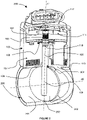
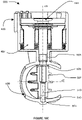
- the figure 1 shows a three-quarter view in partial section of a direct-drive electromagnetic actuator 100 according to the prior art.
- the electromagnetic actuator 100 comprises a fixed stator assembly 107 consisting of several ferromagnetic poles 112 surrounded by a coil 111 and connected to each other by a ferromagnetic base 110, the stator assembly 107 being overmoulded with a plastic material 113.
- the actuator 100 also comprises a rotor assembly 114 movable in rotation composed of a ferromagnetic yoke 102 carrying a multipolar permanent magnet 104.
- the rotor 114 also comprises a transmission shaft 106 force-fitted into the yoke 102 at the level of a specific zone 103 providing a recessed type connection, the lower end 109 of the shaft 106 being adapted according to the member to be controlled.
- a magnetic target 101 in the form of a permanent magnet is also fixed to the rotor 114 at the level of the yoke 102. This magnetic target 101 collaborates with a sensitive element 115 of the cover 117 capable of detecting the actual position of the rotor 114 relative to the stator 107
- the cover 117 is made of plastic material 116 and comprises an electrical interface 118, the cover 117 is fixed by gluing or by welding to the stator 107 via the plastic overmolding 113.
- the rotor 114 collaborates with the stator 107 by means of a thrust ball bearing 105 providing a support-plan type connection and eliminating 3 degrees of freedom between the yoke 102 and the plastic overmolding 113, thus taking up the forces of attraction under the effect of the permanent magnet 104 and the coils 111 and allowing relative rotation with minimum friction.
- the rotor 114 also collaborates with the stator 107 by means of an adjusted plain bearing 108 producing a sliding pivot type connection and eliminating 4 degrees of freedom between the transmission shaft 106 and the plastic overmoulding 113.
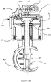
- the figure 2 shows a three-quarter view in partial section of a motorized valve 300 driven by a direct drive actuator 100 according to the prior art.
- the actuator 100 consists of a fixed stator assembly 107, a mobile rotor assembly 114 and a cover 117, the stator 107 and the rotor 114 being in hyperstatic pivot connection as described on the figure 1 .
- the plastic overmolding 113 of the stator 107 comprises, in a zone located under the fitted slide bearing 108, a duct 200 of tubular shape and oriented along the straight line (d2).
- the transmission shaft 106 has at its lower end 109 a specific shape capable of receiving and carrying rigidly (by screws not shown in the figure) a shutter valve 202 capable of opening the pipe 200 to a greater or lesser extent according to its relative angular position.
- a shutter valve 202 capable of opening the pipe 200 to a greater or lesser extent according to its relative angular position.
- the valve 202 collaborates and comes into contact with the inner surface 201 of the duct 200 to ensure closure with a given level of tightness, the valve 202 being driven in rotation by means of the transmission shaft 106 secured to the rotor 114 at the level of the connection 103.
- the axial positioning along the line (d1) of the valve 202, and therefore the level of sealing achieved, relative to the inner surface 201 of the duct 200 depends of the entire chain of dimensions involving respectively the distance of the plastic overmolding 113 between the straight line (d2) and the support of the ball bearing 105, the thickness of the ball bearing 105, the fitting length of the shaft 106 between link 103 and its lower end, the length of shaft 106 between its lower end and the specific fixing area 109 of valve 202, the precision of the fixing of valve 202 on part 109 of shaft 106 , the outside diameter of the valve 202.
- Non-functional and penalizing games resulting from the stacking of all the tolerances of the chain of dimensions then appear at the level of the upper 204 or lower part 203 between the valve 202 and the inner diameter 201 of the pipe 200, severely limiting the level of waterproofing.
- the transmission shaft 106 is floating in the duct 200 and cantilever the valve 202: its lower end is not taken up or guided in the duct 200 at the level of the lower zone 203 in order to avoid further increase the degree of hyperstatism of its guidance.
- the forces induced by the pressure of the gases on the valve 202 in a direction parallel to the axis (d2) will then friction stress and over-constrain the guiding of the shaft 106, in particular at the level of the sliding bearing adjusted 108 and thrust ball bearing 105.
- the play present in the zone lower 203 will thus be increased, following the bending by elastic deformation of the transmission shaft 106 and of the fitted plain bearing 108, further reducing the sealing performance.
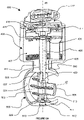
- the picture 3 shows a three-quarter view in partial section of a preferred embodiment of an electromagnetic actuator 400 with direct drive according to the invention.
- the electromagnetic actuator 400 comprises a fixed stator assembly 407 consisting of several ferromagnetic poles 412 surrounded by a winding 411 and interconnected by a ferromagnetic base 410, the stator assembly 407 being molded with a plastic material 413.
- 400 also comprises a rotor assembly 414 mobile in rotation composed of a ferromagnetic yoke 402 carrying a multipolar permanent magnet 404, the rotor 414 being linked to the stator 407 by means of a thrust ball bearing 405 taken between the yoke 402 and the plastic overmolding 413.
- the actuator 400 also comprises a cover 417 made of plastic material 416 and fixed to the stator 407 via the plastic overmolding 413, the cover 417 being provided with an electrical interface 418 in the form of a connector and a a sensitive element 415 for detecting the angular position.
- a transmission shaft 406 is also provided: it comprises at its lower end a specific shape 409 able to be linked to the application to be driven, it is secured at its upper end to a connecting element 419 via a recessed type connection 403 , made for example by plastic overmolding.
- the connecting element 419 is free relative to the cylinder head via a functional clearance 421 prohibiting any contact in order to avoid problems of hyperstatism.
- the connecting element 419 is provided with several rotational coupling means 422 capable of transmitting the rotational movement of the yoke 402 to the shaft 406 via the connection 403, the coupling means 422 also ensuring the positioning of the transmission shaft 406.
- the connecting element 419 also incorporates a magnetic target 401 capable of collaborating with the sensitive element 415 of the cover 417.
- the actuator 400 is provided with a position return system in the form of a a multipolar permanent magnet 420 fixed to the stator 407 at the level of the ferromagnetic poles 412, the fixed return magnet 420 collaborating with the mobile motor magnet 404 to create a return torque such as, for example, described in the patent EP0886875 .
- the transmission shaft 406 collaborates with the stator 407 at the level of a bearing 408 produced by the plastic overmolding 413 or by an attached bearing (not shown in the figure).
- the bearing 408 can be with a functional clearance prohibiting any contact between the transmission shaft 406 and the stator 407, the guiding of the the shaft 406 being in this case provided by the guide elements of the member to be controlled, the shaft 406 being secured to the member to be controlled; the bearing 408 can also be adjusted to guarantee correct centering with the stator 407, the bearing 408 being in this case one of the guiding elements of the member to be driven if the shaft 406 is integral with the member to be driven, a specific coupling system that may be necessary between the shaft 406 and the member to be driven if the member to be driven has its own guides.
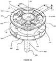
- the figure 4A shows an exploded detail view of a first embodiment of the connecting element 419 between the transmission shaft 406 and the rotor 414 of the direct-drive actuator 400 according to the invention.
- the connecting element 419 is preferably but not limited to plastic material, it is molded and rigidly fixed to the transmission shaft 406 via a central part 423 secured to the end of the shaft 406. This central part 423 also incorporates a surface 421 penetrating the center of the yoke 402 but never coming into contact, and a magnetic target 401 made by bi-injection or overmolding.
- the connecting element 419 also comprises a peripheral zone 424 having a high tangential rigidity relative to the axis (d3).
- This outer annular portion 424 is equipped with coupling means in the form of clutch pins 422 collaborating with complementary housings 426 belonging to the cylinder head 402 in order to carry out a transmission of the engine torque from the rotor 414 to the transmission shaft 406 in eliminating any relative movement between the yoke 402 and the connecting element 419 in a direction tangential to the axis (d3).
- the connecting element 419 also comprises connecting arms 425 making it possible to secure the peripheral zone 424, connected in rotation to the cylinder head 402, to the central zone 423 rigidly connected to the transmission shaft 406. Radially to the axis ( d3), the connecting arms 425 have an effective length D, a section of width L and of thickness E.
- the connecting element 419, via the peripheral zone 424, the connecting arms 425 and the central part 423 creates a play-free connection, based on the elasticity and rigidity of its various constituent parts, at 3 degrees of freedom between the rotor 414 and the transmission shaft 406.
- This center connection ⁇ is of the finger ball joint type with an additional translation: it thus allows 2 degrees of freedom in rotation around the axes (d4) and (d5) and a degree of freedom in translation along the axis (d3).
- the figure 4B shows an exploded detail view in partial section of a second embodiment of the connecting element 419 between the transmission shaft 406 and the rotor 414 of the direct drive actuator 400 according to the invention.
- the connecting element 419 is made of plastic material, it overmolds a metal insert 427 which is rigidly fixed by fitting in force on the upper end of the transmission shaft 406.
- the insert 427 comprises a specific zone 421b having grooves or knurling in order to ensure good cohesion with the connecting element 419, it also incorporates a surface 421a penetrating into the center of the yoke 402 but without ever coming into contact, and a magnetic target 401 attached and glued.
- the connecting element 419 also comprises a peripheral zone 424 having a high tangential rigidity relative to the axis (d3).
- This outer annular portion 424 is equipped with coupling means in the form of clutch pins 422 collaborating with complementary housings 426 belonging to the cylinder head 402 in order to carry out a transmission of the engine torque from the rotor 414 to the transmission shaft 406 in eliminating any relative movement between the yoke 402 and the connecting element 419 in a direction tangential to the axis (d3).
- the connecting element 419 also comprises connecting arms 425 making it possible to secure the peripheral zone 424 connected in rotation to the yoke 402 of the central zone 423 overmolding the insert 427 rigidly fixed to the transmission shaft 406.
- connection 425 perform the same function and are dimensioned as described on the figure 4A .
- the connecting element 419, via the peripheral zone 424, the connecting arms 425, the central part 423 and the insert 427 creates a connection without play, relying on the elasticity and the rigidity of its different constituent parts, with 3 degrees of freedom between the rotor 414 and the transmission shaft 406.
- This center connection ⁇ is of the ball and socket type with an additional translation: it thus allows 2 degrees of freedom in rotation around the axes ( d4) and (d5) and a degree of freedom in translation along the axis (d3).
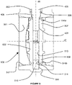
- the figure 5 shows a partial sectional view of a first embodiment of a motorized valve 600 driven by a direct-drive electromagnetic actuator 400 according to the invention.
- the actuator 400 consists of a stator 407, a cover 417 and a rotor 414, it comprises a transmission shaft 406 linked to the rotor 414 via an element connection 419.
- the stator 407 includes a return system in position 420, it is overmolded with a plastic material 413 in contact with the cover 417 and extending over the lower part of the actuator 400 to form a tubular pipe 500 , the inner surface 501 of the pipe 500 collaborating with a shutter valve 502 via a sealing element 505 fixed on the periphery of the valve 502.
- the shutter valve 502 is driven in rotation by the transmission shaft 406 which crosses it entirely: the shaft 406 is provided with a first specific surface 429 extending axially along the line (d6), a flat for example , collaborating with the 2 upper 507 and lower 508 passages of the shaft 406 through the valve 502 to drive and rotate it.
- the shaft 406 is also provided with a second specific surface 430 extending circumferentially along the line (d6), a groove for example, collaborating with the clips 509 of the valve 502 to ensure the axial retention of the transmission shaft 406 along the line (d6), the outer diameter of the valve 502 and of the sealing element 505 being adjusted to the diameter of the inner surface 501 of the pipe 500.
- This type of assembly makes it possible to guarantee an optimum relative positioning between the valve 502 and the surface 501 of the pipe 500, the positioning only depending on the manufacturing and adjustment tolerances of the valve 502 and of the surface 501, the valve 502 no longer being axially and directly positioned along the straight line (d6) by drive shaft 406.
- the transmission shaft 406 comprises a specific intermediate surface 428 in annular linear connection with a bearing 503, attached or directly produced by the overmolding 413, in the upper zone valve 502 belonging to conduit 500, this connection eliminating 2 degrees of freedom in translation in a first plane located above valve 502 and orthogonal to the right (d6).
- the bearing 503 incorporates a dynamic sealing element 506 between the shaft 406 and the duct 500 in order to prevent the fluid circulating in the duct 500 in the direction (d7) from rising in the actuator 400 in the direction (d6) .
- the transmission shaft 406 also comprises at its lower end a specific surface 431 in annular linear connection with a bearing 504, attached or directly produced by the overmolding 413 in the lower zone of the valve 502 belonging to the duct 500, this connection eliminating 2 degrees freedom in translation in a second plane located below the valve 502 and orthogonal to the line (d6).
- the clips 509 of the valve 502, fitted to the surface 501 of the valve 500, collaborating with the groove 430 of the shaft 406 remove 1 degree of freedom in translation along the straight line (d6).
- the resulting connection thus obtained between the control shaft 406 and the plastic molding 413 of the valve 600 is a connection with a single degree of freedom of the pivot type and isostatic in nature.
- the Figure 6A shows a partial sectional view of a second embodiment of a motorized valve 600 driven by a direct-drive electromagnetic actuator 400 according to the invention.
- the shutter valve 502 is driven in rotation by the transmission shaft 406: the shaft 406 is provided with a specific surface 429 extending axially along the line (d6), a flat for example, collaborating with the passage upper 507 of shaft 406 through valve 502 to drive and rotate it.
- valve 502 and of the sealing element 505 are adjusted to the diameter of the inner surface 501 of the pipe 500: this type of assembly makes it possible to guarantee optimum relative positioning between the valve 502 and the surface 501 of the pipe 500, the positioning only depending on the manufacturing tolerances and adjustment of the valve 502 and of the surface 501, the valve 502 no longer being axially and directly positioned along the line (d6) by the control shaft 406.
- the transmission shaft 406 comprises a specific intermediate surface 428 in annular linear connection or ball joint with a bearing 503, attached or directly produced by the overmoulding 413, in the upper zone of valve 502 belonging to conduit 500, this connection eliminating 2 degrees of freedom in translation in a first plane located above valve 502 and orthogonal to the line (d6) and possibly eliminating one degree of freedom in translation along the line (d6).
- the bearing 503 incorporates a dynamic sealing element 506 between the shaft 406 and the duct 500 in order to prevent the fluid circulating in the duct 500 in the direction (d7) from rising in the actuator 400 in the direction (d6) .
- the valve 600 also comprises a stud 510 emerging radially inside the pipe 500, the stud 510 being open and embedded from the outside in the pipe 500, the stud 510 being associated with an O-ring 512 to ensure sealing. .
- the hemispherical end 511 of the stud 510 cooperates with the bearing 513 at the level of the passage 508 of the valve 502 to form an annular linear connection or ball joint, this connection eliminating 2 degrees of freedom in translation in a second plane located below the valve 502 and orthogonal to the line (d6) and possibly eliminating a degree of freedom in translation along the line (d6).
- the movement and positioning by the rotor 414 of the valve 502 by means of the control shaft 406 is thus carried out in an isostatic and precise manner, without inducing over-stress on the guide elements 503 and 513 distributed in either side of valve 502.
- the figure 6B shows a partial sectional view of a third embodiment of a motorized valve 600 controlled by an electromagnetic actuator 400 with direct drive according to the invention.
- the valve 600 also comprises a stud 510 emerging radially inside the pipe 500, the stud 510 being non-emerging and embedded from the inside in the pipe 500.
- a niche 513 provided inside and in the center of the valve 502 at the level of its lower part 508 makes it possible to fully house the stud 510 in the valve 502 when inserting the valve 502 into the conduit 500 in one direction (d7).
- an assembly element (not shown in the figure) through the stator 407 of the actuator 400, through the upper bearing 503 of the valve 500 and through the upper part 507 of the valve 502 comes into contact on the upper part of stud 510 to embed it in the blind bore 514 of conduit 500 in one direction (d6).
- the hemispherical end 511 of the stud 510 cooperates with the bearing located in the lower part of the niche 513 at the level of the passage 508 of the valve 502 to form an annular linear connection or ball joint, this connection eliminating 2 degrees of freedom in translation in a second plane. located below the valve 502 and orthogonal to the line (d6) and possibly eliminating a degree of freedom in translation along the line (d6).
- the movement and positioning by the rotor 414 of the valve 502 by means of the control shaft 406 is thus carried out in an isostatic and precise manner, without inducing over-stress on the guide elements 503 and 513 distributed in either side of valve 502.
- the figure 7 shows a detailed view of a preferred embodiment of a shutter valve 502 of a motorized valve 600 controlled by an electromagnetic actuator 400 with direct drive according to the invention.
- the closure valve 502 preferably made of plastic, is associated with a sealing element 505 which can be produced by bi-injection, overmolding of the valve 502 or simply fixed by gluing, the element of sealing 505 preferably being a flexible material of the elastomer type.
- the sealing element 505 consists of two annular branches 515a-515b located at the periphery of the valve 502, each annular branch 515a and 515b being on a different face of the valve 502, the annular branches being provided to cooperate with the inner wall 501 of the duct 500 to seal in the closed position.
- the sealing element 505 also consists of two branches of substantially toroidal shapes 516a-516b arranged on the two transverse end surfaces surrounding the shaft passages 507 and 508, the branches 516a and 516b being provided to be in permanent contact with the inner surface 501 of the duct 500 with the aim of sealing in the closed position, with the aim of sealing the contact between the shafts and the duct, and with the aim of prohibiting particles pollutants from coming to agglomerate on the trees so as not to block the valve 502 in rotation.
- the two annular branches 515a-515b and the substantially toroidal branches 516a-516b are interconnected to form a sealing element 505 in one piece.
- the figure 8 shows a detail view in section of a preferred embodiment of the lower part of the conduit 500 of a motorized valve 600 controlled by an electromagnetic actuator 400 with direct drive according to the invention.
- the shutter valve 502 is equipped with a sealing element 505 of which only the branches 516a-516b located towards the shaft passages 507 and 508 are visible. These two branches 516a-516b are in permanent contact with the inner surface 501 of the duct 500: they thus effectively protect the shaft 406 and the stud 510 from any polluting particles that may come in and block the rotation of the valve 502.
- These two branches 516a-516b also participate in sealing the duct in the closed position insofar as they eliminate the leak paths which may be found in the upper and lower zone of the valve 502 at the level of the shaft passages 507-508.
- the transmission shaft 406 engages the valve 502 at the level of the passage 507, it causes it to rotate via a flat 429.
- the shaft 406 is guided by the valve 500 with a bearing 503 in contact with a specific surface 428 creating a connection of the linear annular or ball joint type, this connection being sealed by a dynamic seal 506, this seal being redundant, and therefore optional, with the sealing branch 516a of the valve 502.
- the lower part of the valve 502 is guided by a stud 510 fixed with the valve 500.
- the stud 510 is housed in the niche 513 of the valve 502.
- the assembly system (not shown in the figure) embeds the stud 510 in the blind bore 514 of the valve 500 through the bearing 503 and of the valve 502, the transmission shaft 406 not yet being inserted.
- the hemispherical end 511 of the stud 510 then cooperates with the lower part of the recess 513 to form a connection of the linear annular or ball joint type.
- the sealing branch 516b of the valve 502 is in permanent contact with the inner surface 501 of the valve 500
- This surface 501 also includes a zone 517 located around the sealing branch 516b, this zone 517 has a frustoconical or sloping shape capable of naturally evacuating under the effect of gravity the polluting particles likely to accumulate near the stud 510, the line (d6) being generally oriented vertically.
- the figure 9 shows a sectional view of a preferred embodiment of the conduit 500 of the motorized valve 600 in the closed position controlled by an electromagnetic actuator 400 with direct drive according to the invention.
- the inner surface 501 of the conduit 500 comprises two shoulders 518a-518b penetrating substantially radially in the direction of the axis (d7) of the conduit 500. These two shoulders provide a rigid stop to the valve 502 in the closed position and collaborate with the peripheral branches of sealing 515a-515b to sufficiently seal the closed position, the sealing branches 515a-515b respectively coming into contact on the shoulders 518a-518b.
- the figure 10A shows a sectional view of a preferred embodiment of a manufacturing phase of a motorized valve 600 controlled by an electromagnetic actuator 400 with direct drive according to the invention.
- This manufacturing phase corresponds to the overmolding operation of the stator 407 consisting of ferromagnetic poles 412 surrounded by a winding 411 and interconnected by a ferromagnetic base 410.
- the return element in position 420 is already integrated on the poles 412 at the level of the upper part, slightly recessed so as to be completely overmoulded.
- the plastic overmolding 413 can thus completely enclose the stator 407, in particular under the lower surface of the base 410.
- the plastic overmolding 413 will produce the bearing 408 of the actuator 400 and the conduit 500 of the motorized valve 600, the conduit 500 comprising an inner surface 501, a blind bore 514 and the radial shoulders 518b-518a.
- the plastic overmolding 413 thus performs the overmolding of the actuator 400 and the duct 500 in one piece and in a single operation: the plastic overmolding 413 thus allows the mechanical connection and precise relative positioning between these two elements.
- the figure 10B shows a sectional view of a preferred embodiment in a first assembly step of a motorized valve 600 driven by an electromagnetic actuator 400 with direct drive according to the invention.
- this first assembly step consists in integrating into the bearing 408 of the actuator 400 and in the direction (d6) an attached guide bearing 503 and an optional dynamic seal 506.
- This first step also consists in integrating the rotor 414 composed of a thrust ball bearing 405, a ferromagnetic yoke 402 and a permanent magnet 404.
- the motor tests of the actuator 400 are carried out, in particular the measurement of the motor torque when the winding 411 is energized, the measurement of the restoring torque resulting from the interaction between the motor magnet 404 and the return system 420 when the winding 411 is not powered and the measurement of the friction under load of the thrust bearing.
- the figure 10C shows a sectional view of a preferred embodiment in a second assembly step of a motorized valve 600 driven by an electromagnetic actuator 400 with direct drive according to the invention.
- this second assembly step consists of integrating into the duct 500 and in the direction (d7) a shutter valve 502 comprising a sealing element 505 and a stud 510 housed in a niche 513 of the valve 502.
- the assembly system (not shown in the figure) embeds the stud 510 in the blind bore 514 of the valve 500 through the rotor 414, the bearing 503 and the valve 502.
- the figure 10D shows a sectional view of a preferred embodiment in a third assembly step of a motorized valve 600 driven by an electromagnetic actuator 400 with direct drive according to the invention.
- this third assembly step consists of integrating in one direction (d6) a transmission shaft 406 which will be connected in rotation via a connecting element 419 to the rotor 414 and which will be connected in rotation via a flat 429 to the valve d shutter 502.
- the connecting element 419 includes a magnetic target 401.
- the figure 10E shows a sectional view of a preferred embodiment in a fourth assembly step of a motorized valve 600 driven by an electromagnetic actuator 400 with direct drive according to the invention.
- this fourth assembly step consists in integrating a cover 417 provided with an electrical interface 418.
- the cover 417 is fixed on the stator 407, it is also equipped with a sensitive element 415 collaborating with the magnetic target 401 for the detection of the angular position.
- the programming of the sensitive element 415 relative to the magnetic target 401 is carried out.
- the winding 411 of the stator 407 is supplied a first time in order to bring the valve 502 into the fully open position, this position is then programmed in the sensitive element 415; the power is supplied a second time or the power is cut to have the return torque in position, to bring the valve 502 into the fully closed position, this position is then programmed in the sensitive element 415.
Landscapes
- Engineering & Computer Science (AREA)
- General Engineering & Computer Science (AREA)
- Mechanical Engineering (AREA)
- Chemical & Material Sciences (AREA)
- Combustion & Propulsion (AREA)
- Power Engineering (AREA)
- Magnetically Actuated Valves (AREA)
- Electrically Driven Valve-Operating Means (AREA)
Description
- L'invention se rapporte au domaine des systèmes électriques d'entrainement et plus particulièrement aux actionneurs électromagnétiques destinés à entrainer en rotation et en prise directe un élément mobile appartenant à un système mécanique complémentaire tel que des vannes intervenant dans la régulation de la circulation de fluide pour applications industrielles, automobiles notamment.
- La liaison entre la partie mobile de l'actionneur et l'organe spécifique entrainé en rotation se fait traditionnellement au moyen d'un arbre d'accouplement réalisant la transmission du mouvement. Généralement, la partie mobile de l'actionneur comporte ses propres moyens de guidage par palier pour assurer la qualité du positionnement, et l'organe spécifique entrainé comporte également ses propres moyens de guidage, notamment par palier. La multiplication des paliers de guidage dans l'actionneur et dans le système mécanique complémentaire entraine un phénomène hyperstatique sur l'axe d'accouplement.
- De manière spécifique mais non limitative, l'invention concerne le domaine particulier des vannes motorisées. Ces vannes, constituées principalement d'un conduit de forme sensiblement tubulaire dans lequel se trouve un clapet d'obturation apte à fermer plus ou moins le conduit, sont présentes dans de nombreuses applications industrielles, notamment automobiles, où elles interviennent dans la régulation de fluide, essentiellement au niveau de la boucle d'air du moteur à combustion du côté admission et du côté échappement. Le clapet d'obturation est lié via un arbre de transmission à un actionneur de type électromagnétique conçu pour déplacer et positionner correctement le clapet dans le conduit entre une première position extrême correspondant à une ouverture maximum du conduit et une deuxième position extrême correspondant à une fermeture maximum du conduit, avec un niveau d'étanchéité donné.
- Selon leur localisation sur la boucle d'air du moteur à combustion, ces vannes peuvent être fabriquées en métal ou en plastique, les clapets sont directement fixés ou reliés par l'intermédiaire d'un mécanisme de réduction à la partie mobile de l'actionneur ; les niveaux d'étanchéité dans la position de fermeture maximum peuvent être plus ou moins exigeants, par exemple un débit de fuite de 30L.min-1 pour une différence de pression ΔP=0.6bar. Pour atteindre ces spécifications, il convient de soigner particulièrement la réalisation du guidage entre le clapet d'obturation et le conduit de la vanne, et la liaison entre la partie mobile de l'actionneur et le clapet.
- L'état actuel de la technique offre de nombreuses solutions pour des actionneurs à entrainement direct destinés notamment au pilotage de vanne de régulation de fluide.
- A titre d'exemple, les brevets
WO9211686 WO2007012711 décrivent un actionneur électromagnétique monophasé destiné à déplacer un organe mobile sur une course limitée, comportant une structure statorique bobinée et un organe mobile à aimant permanent. L'organe mobile est muni d'un arbre d'accouplement rendu solidaire par emmanchement en force de l'extrémité de l'arbre dans la partie ferromagnétique de l'organe mobile. La demande de brevetWO2014072605 revendique une vanne motorisée associant un actionneur électromagnétique selon les brevetsWO9211686 WO2007012711 à une matière surmoulante plastique formant au moins en partie la tubulure de la vanne et solidaire en partie de l'actionneur, le clapet d'obturation étant porté et positionné par l'axe de l'actionneur. Bien que ces solutions présentent des avantages significatifs, notamment via le très faible encombrement des systèmes proposés, des inconvénients majeurs persistent. En effet, l'arbre d'accouplement de l'actionneur est à une première extrémité rigidement solidarisé au rotor de l'actionneur, il porte à sa deuxième extrémité de manière rigide par l'intermédiaire de vis de fixation le clapet d'obturation collaborant avec le conduit. Ainsi pour éviter d'aboutir à un guidage trop hyperstatique de l'arbre d'accouplement, l'arbre d'accouplement n'est guidé que sur sa partie supérieure, au-dessus du clapet, il n'est pas guidé sur sa partie inférieure, au-dessous du clapet. D'une part, le positionnement axial relatif entre le clapet et la tubulure est dépendant des tolérances de fabrication de l'arbre, de la tubulure, de l'actionneur et des procédés d'assemblage notamment la longueur d'emmanchement en force de l'arbre d'accouplement dans le rotor de l'actionneur et la fixation par éléments filetés du clapet sur l'arbre. Des jeux apparaissent alors en position fermée sur les parties supérieures ou inférieures du clapet entre la tubulure et le clapet, dégradant sévèrement les performances d'étanchéité de la vanne requises par l'application. D'autre part, l'absence de reprise de guidage de l'arbre d'accouplement dans sa partie inférieure, sous le clapet, sollicite très fortement les guidages dans sa partie supérieure : les efforts importants induits par ce phénomène de porte-à-faux provoquent des frottements conséquents qui réduisent les performances et le rendement de l'actionneur et qui, à terme, peuvent détruire ces guidages. L'absence de reprise de guidage limite également la rigidité du maintien du clapet dans le conduit, ce qui favorise fortement les fuites sous le clapet, suite à la déformation par flexion de l'arbre d'accouplement et de ses guidages sous l'effet de la pression exercée en position fermée sur le clapet. - On connait par ailleurs la demande
EP2597294 décrivant une vanne, en particulier pour la recirculation des gaz d'échappement basse pression dans le domaine automobile, associant un actionneur rotatif indépendant intégrant un axe de commande sortant de l'actionneur, l'actionneur intégrant ses propres paliers de guidage de l'axe de commande. Cet actionneur est rapporté et fixé sur une vanne métallique par l'intermédiaire de vis de fixation, l'axe de commande de l'actionneur pénètre à l'intérieur du conduit de la vanne, la vanne intégrant ses propres paliers de guidage de l'axe de commande. La partie de l'axe de commande pénétrant dans le conduit porte de manière rigide par l'intermédiaire de nouvelles vis de fixation un clapet circulaire collaborant avec le conduit de la vanne pour fermer plus ou moins la vanne. Le principal inconvénient de la solution proposée par ce brevet est le caractère hyperstatique du guidage de l'arbre d'entrainement du rotor. Cet arbre est guidé par plusieurs paliers localisés dans l'actionneur et dans la vanne, l'actionneur et la vanne étant ici deux composants distincts reliés entre eux de manière rigide par des vis. Ce type de montage crée ainsi une liaison hyperstatique occasionnant des contraintes importantes sur les guidages dès lors que l'actionneur et la vanne ne sont pas parfaitement et rigoureusement alignés ou dès lors que l'emmanchement en force de l'arbre de commande dans le rotor de l'actionneur n'est pas effectué avec un battement parfait. D'autres solutions proposées dans ce même brevet consistent à intégrer un palier supplémentaire prévu à l'extrémité inférieure de l'arbre sous le clapet d'obturation, ce qui augmente encore ce problème. Un autre inconvénient de cette réalisation réside dans l'obtention des niveaux d'étanchéité requis par l'application en position fermée : là encore le clapet devant collaborer avec la tubulure est rigidement fixé à l'extrémité de l'axe, l'axe étant lui-même rigidement fixé au rotor de l'actionneur, l'actionneur étant lui-même rapporté et rigidement fixé sur la vanne par les vis. Le positionnement du clapet dans le conduit est alors peu précis et des jeux favorisant les fuites apparaissent dans les zones supérieures et inférieures du clapet. Enfin un dernier inconvénient de cette intégration est l'absence de reprise de guidage de l'axe dans la zone inférieure du clapet qui limite la rigidité du maintien du clapet dans le conduit, ce qui favorise fortement les fuites sous le clapet, suite à la déformation par flexion de l'axe de commande et de ses guidages sous l'effet de la pression exercée en position fermée sur le clapet. - On connait alors, dans l'état de la technique, le brevet
EP2020492 résolvant le problème d'hyperstatisme en associant un actionneur électrique coopérant avec un capteur de position pour commander le pivotement d'un volet d'étranglement d'une vanne pour moteur à combustion, l'actionneur électrique étant rapporté et fixé sur la vanne d'étranglement par des vis de fixation. Le système décrit comporte des moyens de liaisons créant un découplage mécanique similaire à un joint de cardan entre l'axe de commande et l'axe de pivotement du volet. Bien que pertinente, cette solution comporte de nombreux inconvénients, notamment par la présence nécessaire de deux axes distincts, un dans l'actionneur et un dans la vanne, reliés entre eux par l'introduction d'une pièce supplémentaire qui réalise le découplage mais qui complexifie sévèrement la chaine de transmission du mouvement : l'extrémité des deux axes doivent intégrer des leviers spécifiques dont l'extrémité est sphérique, les tolérances de fabrication et d'assemblage de la pièce supplémentaire ainsi que l'encombrement nécessaire à son intégration et à son montage entre les deux axes augmentent le coût, l'espace nécessaire et réduisent la qualité de la transmission, notamment par l'apparition de jeux résultant de l'usure de cette pièce additionnelle au niveau des extrémités sphériques. D'autres actionneurs électromagnétiques rotatifs génériques sont décrits dans les documentsJP 2001 352701 A WO 2004/084376 A1 etDE 10 2008 018460 A1 . - L'art antérieur offre ainsi de nombreuses solutions dont aucune n'est réellement satisfaisante.
- Soit l'arbre d'accouplement est monobloc et unique entre l'actionneur et la vanne, son guidage est alors hyperstatique. Le clapet est directement porté par l'arbre d'accouplement qui est monté flottant et en porte-à-faux dans le conduit, pour éviter un guidage supplémentaire dans la zone inférieure du clapet qui augmenterait encore le degré d'hyperstatisme. Les défaillances liées à l'usure par frottement, les coûts d'usinage élevés de l'arbre et des portées de guidage ainsi que les fuites en position fermée très difficiles à maîtriser rendent cette solution inappropriée.
- Soit l'arbre portant le clapet est correctement guidé dans le conduit de part et d'autre du clapet, alors il doit être dissocié et donc accouplé à l'arbre de l'actionneur avec un moyen de liaison évitant les problèmes d'hyperstatisme. Le système intègre alors au minimum deux arbres différents et le moyen de liaison est souvent complexe, encombrant et couteux si l'actionneur est à entrainement direct. On peut avoir recours à un actionnement par moteur à courant continu associé à un réducteur à engrenages mais on perd dans ce cas les avantages de compacité et fiabilité de l'entraînement direct.
- L'objet de l'invention est ainsi de répondre aux problèmes exposés précédemment en proposant un actionneur à entrainement direct pour vannes motorisées permettant non seulement de solutionner les problématiques d'hyperstatisme mais également de garantir un positionnement précis de l'organe spécifique à piloter dans un encombrement minimum et avec un niveau de fiabilité amélioré.
- A cet effet et dans son acceptation la plus générale, l'invention concerne un actionneur électromagnétique rotatif présentant un axe de rotation, comprenant un stator fixe et un rotor mobile autour dudit axe, ledit rotor entraînant par l'intermédiaire d'un arbre de transmission unique un organe extérieur lié audit arbre caractérisé en ce que la liaison entre ledit rotor et ledit arbre est assurée par un moyen de liaison mécanique combinant une liaison de type rotule à doigt et un degré de liberté en translation axiale.
- Avantageusement, ledit moyen de liaison mécanique est de forme discale, il est constitué par une partie centrale à haute rigidité isotropique solidaire de l'arbre de transmission, une partie périphérique à haute rigidité tangentielle liée audit rotor et ladite partie centrale et ladite partie périphérique sont liées par l'intermédiaire de n bras 425 s'étendant radialement, chaque bras 425 présentant des rigidités tangentielle et radiale élevées, chaque bras 425 présentant une rigidité axiale faible, n étant ≥ 2, le rapport en la rigidité tangentielle élevée et la rigidité axiale faible étant ≥ 10, le rapport en la rigidité radiale élevée et la rigidité axiale faible étant ≥ 2.5.
- Selon une variante, ledit moyen de liaison mécanique est constitué par une matière plastique surmoulant et solidaire de l'extrémité dudit arbre d'entrainement, ledit surmoulage s'étendant jusqu'au rotor.
- Selon un mode de réalisation particulier, ledit moyen de liaison mécanique comporte un insert métallique entre ledit surmoulage et ledit arbre de transmission.
- Selon une autre variante, le moyen de liaison mécanique comporte une cible magnétique mobile apte à interagir avec un élément sensible récepteur, fixe par rapport à ladite cible, pour fournir un signal de position angulaire.
- Selon un mode de réalisation particulier, la cible magnétique est réalisée par bi-injection ou surmoulage dudit moyen de liaison mécanique.
- Selon une alternative, ladite cible magnétique est rapportée et fixée par collage sur ledit moyen de liaison mécanique.
- Selon un autre mode de réalisation, ledit actionneur comprend un moyen de retour en position de référence sous la forme d'une piste aimantée solidaire dudit stator et apte à interagir sans contact avec ledit rotor pour ramener ledit arbre de commande en une positon prédéterminée par l'intermédiaire dudit moyen de liaison mécanique, lorsque ledit stator n'est plus alimenté en énergie.
- L'invention concerne aussi un procédé d'assemblage d'un actionneur électromagnétique selon l'invention et comprenant au moins deux étapes, une première étape consistant à intégrer ledit rotor audit stator et une deuxième étape consistant à insérer ledit arbre équipé dudit moyen de liaison mécanique au travers dudit rotor et dudit stator.
- Avantageusement, le procédé selon l'invention peut comporter une troisième étape consistant à fixer audit stator un couvercle comportant ledit élément sensible récepteur.
- L'invention concerne encore une vanne motorisée comprenant un actionneur électromagnétique selon l'invention et composée d'un conduit et d'un clapet apte à obturer ledit conduit
- Selon une variante, l'arbre de transmission est guidé par deux paliers seulement disposés de part et d'autre dudit clapet dans la zone du conduit.
- Avantageusement, lesdits paliers forment des liaisons de type linéaire annulaire avec ledit arbre de transmission.
- Selon une variante, le palier inférieur, opposé à l'actionneur, est constitué par un plot en érection par rapport à la paroi intérieure du conduit, et coopérant avec un logement complémentaire prévu dans le clapet.
- Selon une autre variante, ledit plot présente une tête hémisphérique apte à former avec ledit logement complémentaire une liaison de type rotule ou de type linéaire annulaire.
- Selon un mode de réalisation particulier, la surface intérieure dudit conduit présente une zone localisée autour dudit plot ayant une forme tronconique ou pentue apte à évacuer naturellement sous l'effet de la gravité les particules polluantes susceptibles de s'accumuler à proximité dudit plot.
- Avantageusement, le palier du guidage supérieur dudit clapet prévu entre ledit arbre de transmission et ledit stator est un palier enchâssé dans le corps en matière plastique dudit conduit, ledit palier étant étanchéifié par un joint entourant ledit arbre.
- Selon une autre variante, le clapet est entouré par un joint périphérique s'étendant sur les deux branches annulaires aptes à venir en appui contre deux épaulements prévus sur la paroi intérieure dudit conduit, et sur les deux surfaces frontales transversales entourant les passages d'arbres.
- L'invention concerne encore un procédé d'assemblage d'une vanne motorisée comprenant au moins trois étapes, une première étape consistant à intégrer ledit rotor à ladite vanne, une deuxième étape consistant à intégrer ledit clapet dans la dite conduite et une troisième étape consistant à insérer ledit arbre de transmission équipé dudit moyen de liaison mécanique au travers de ladite vanne.
- De préférence, ce procédé comporte une quatrième étape consistant à fixer à ladite vanne un couvercle comportant ledit élément sensible récepteur.
- D'autres caractéristiques et avantages de l'invention ressortiront à la lecture qui suit d'exemples de réalisation détaillés, en référence aux figures annexées qui représentent respectivement :
- La
figure 1 , une vue de trois quart en coupe partielle d'un actionneur électromagnétique à entrainement direct selon l'art antérieur, - La
figure 2 , une vue de trois quart en coupe partielle d'une vanne motorisée pilotée par un actionneur à entrainement direct selon l'art antérieur, - La
figure 3 , une vue de trois quart en coupe partielle d'un mode de réalisation préférentiel d'un actionneur électromagnétique à entrainement direct selon l'invention, - La
figure 4A , une vue de détails en éclatée d'un premier mode de réalisation de l'élément de liaison entre l'arbre de transmission et le rotor de l'actionneur à entrainement direct selon l'invention, - La
figure 4B , une vue de détails en éclatée en coupe partielle d'un second mode de réalisation de l'élément de liaison entre l'arbre de transmission et le rotor de l'actionneur à entrainement direct selon l'invention, - La
figure 5 , une vue en coupe partielle d'un premier mode de réalisation d'une vanne motorisée pilotée par un actionneur électromagnétique à entrainement direct selon l'invention, - La
figure 6A , une vue en coupe partielle d'un second mode de réalisation d'une vanne motorisée pilotée par un actionneur électromagnétique à entrainement direct selon l'invention, - La
figure 6B , une vue en coupe partielle d'un troisième mode de réalisation d'une vanne motorisée pilotée par un actionneur électromagnétique à entrainement direct selon l'invention, - La
figure 7 , une vue de détails d'un mode de réalisation préférentiel d'un clapet d'obturation d'une vanne motorisée pilotée par un actionneur électromagnétique à entrainement direct selon l'invention, - La
figure 8 , une vue de détails en coupe d'un mode de réalisation préférentiel de la partie basse du conduit d'une vanne motorisée pilotée par un actionneur électromagnétique à entrainement direct selon l'invention, - La
figure 9 , une vue en coupe d'un mode de réalisation préférentiel du conduit de la vanne motorisée en position fermée pilotée par un actionneur électromagnétique à entrainement direct selon l'invention, - La
figure 10A , une vue en coupe d'un mode de réalisation préférentiel d'une phase de fabrication d'une vanne motorisée pilotée par un actionneur électromagnétique à entrainement direct selon l'invention, - La
figure 10B , une vue en coupe d'un mode de réalisation préférentiel dans une première étape d'assemblage d'une vanne motorisée pilotée par un actionneur électromagnétique à entrainement direct selon l'invention, - La
figure 10C , une vue en coupe d'un mode de réalisation préférentiel dans une deuxième étape d'assemblage d'une vanne motorisée pilotée par un actionneur électromagnétique à entrainement direct selon l'invention, - La
figure 10D , une vue en coupe d'un mode de réalisation préférentiel dans une troisième étape d'assemblage d'une vanne motorisée pilotée par un actionneur électromagnétique à entrainement direct selon l'invention, - La
figure 10E , une vue en coupe d'un mode de réalisation préférentiel dans une quatrième étape d'assemblage d'une vanne motorisée pilotée par un actionneur électromagnétique à entrainement direct selon l'invention. - La
figure 1 représente une vue de trois quart en coupe partielle d'un actionneur électromagnétique à entrainement direct 100 selon l'art antérieur. L'actionneur électromagnétique 100 comporte un ensemble statorique fixe 107 constitué de plusieurs pôles ferromagnétiques 112 entourés d'un bobinage 111 et reliés entre eux par une base ferromagnétique 110, l'ensemble statorique 107 étant surmoulé d'une matière plastique 113. L'actionneur 100 comporte également un ensemble rotorique 114 mobile en rotation composé d'une culasse ferromagnétique 102 portant un aimant permanent multipolaire 104. Le rotor 114 comporte également un arbre de transmission 106 emmanché en force dans la culasse 102 au niveau d'une zone spécifique 103 réalisant une liaison de type encastrement, l'extrémité inférieure 109 de l'arbre 106 étant adaptée selon l'organe à piloter. Une cible magnétique 101 sous forme d'aimant permanent est aussi fixée sur le rotor 114 au niveau de la culasse 102. Cette cible magnétique 101 collabore avec un élément sensible 115 du couvercle 117 apte à détecter la position réelle du rotor 114 relativement au stator 107. Le couvercle 117 est réalisé en matière plastique 116 et comporte une interface électrique 118, le couvercle 117 est fixé par collage ou par soudage au stator 107 par l'intermédiaire du surmoulage plastique 113. - Le rotor 114 collabore avec le stator 107 par l'intermédiaire d'une butée à billes 105 réalisant une liaison de type appui-plan et supprimant 3 degrés de liberté entre la culasse 102 et le surmoulage plastique 113, reprenant ainsi les efforts d'attraction sous l'effet de l'aimant permanent 104 et des bobines 111 et permettant une rotation relative avec un frottement minium. Le rotor 114 collabore également avec le stator 107 par l'intermédiaire d'un palier lisse ajusté 108 réalisant une liaison de type pivot glissant et supprimant 4 degrés de liberté entre l'arbre de transmission 106 et le surmoulage plastique 113. La liaison au niveau de la zone spécifique 103 entre la culasse 102 et l'arbre de transmission 106 étant de type encastrement, la liaison équivalente et résultante entre le rotor 114 et le stator 107 est une liaison de type pivot supprimant 5 degrés de liberté mais de nature hyperstatique de degré 2. Des défauts de battement entre l'axe de l'arbre de transmission 106 et le plan de la culasse 102, des défauts de perpendicularité entre l'axe du palier lisse ajusté 108 et le plan d'appui de la butée à billes 105 sur le surmoulage plastique 113, des efforts radiaux induits par l'organe piloté par l'actionneur 100 au niveau de l'extrémité 109 de l'arbre de transmission 106 vont alors induire des surcontraintes significatives, inutiles et pénalisantes sur les guidages au niveau du palier lisse et ajusté 108 et au niveau de la butée à billes 105, réduisant ainsi les performances et limitant la robustesse de l'actionneur électromagnétique 100.
- La
figure 2 représente une vue de trois quart en coupe partielle d'une vanne motorisée 300 pilotée par un actionneur à entrainement direct 100 selon l'art antérieur. L'actionneur 100 est constitué d'un ensemble statorique fixe 107, d'un ensemble rotorique mobile 114 et d'un couvercle 117, le stator 107 et le rotor 114 étant en liaison pivot hyperstatique tel que décrit sur lafigure 1 . Le surmoulage plastique 113 du stator 107 comporte dans une zone située sous le palier lisse ajusté 108 un conduit 200 de forme tubulaire et orienté selon la droite (d2). L'arbre de transmission 106 comporte à son extrémité inférieure 109 une forme spécifique apte à recevoir et porter de manière rigide (par des vis non représentées sur la figure) un clapet d'obturation 202 apte à ouvrir plus ou moins la conduite 200 selon sa position angulaire relative. En position de pleine fermeture telle que représentée, le clapet 202 collabore et vient en contact avec la surface intérieure 201 du conduit 200 pour assurer une fermeture avec un niveau d'étanchéité donné, le clapet 202 étant entrainé en rotation par l'intermédiaire de l'arbre de transmission 106 solidaire du rotor 114 au niveau de la liaison 103. Ainsi, le positionnement axial selon la droite (d1) du clapet 202, et donc le niveau d'étanchéité atteint, relativement à la surface intérieure 201 du conduit 200 dépend de toute la chaine de cotes faisant intervenir respectivement la distance du surmoulage pastique 113 entre la droite (d2) et l'appui de la butée à billes 105, l'épaisseur de la butée à billes 105, la longueur d'emmanchement de l'arbre 106 entre la liaison 103 et son extrémité inférieure, la longueur de l'arbre 106 entre son extrémité inférieure et la zone spécifique de fixation 109 du clapet 202, la précision de la fixation du clapet 202 sur la partie 109 de l'arbre 106, le diamètre extérieur du clapet 202. Des jeux non fonctionnels et pénalisants résultant de l'empilement de toutes les tolérances de la chaine de cotes apparaissent alors au niveau de la partie supérieure 204 ou inférieure 203 entre le clapet 202 et le diamètre intérieur 201 de la conduite 200, limitant sévèrement le niveau d'étanchéité. - L'arbre de transmission 106 est flottant dans le conduit 200 et porte en porte-à-faux le clapet 202 : son extrémité inférieure n'est pas reprise ni guidée dans le conduit 200 au niveau de la zone inférieure 203 afin d'éviter d'augmenter encore le degré d'hyperstatisme de son guidage. En position fermée, les efforts induits par la pression des gaz sur le clapet 202 selon une direction parallèle à l'axe (d2) vont alors frottement solliciter et sur-contraindre le guidage de l'arbre 106, notamment au niveau du palier lisse ajusté 108 et de la butée à billes 105. Le jeu présent au niveau de la zone inférieure 203 va ainsi être augmenté, suite à la flexion par déformation élastique de l'arbre de transmission 106 et du palier lisse ajusté 108, réduisant encore les performances d'étanchéité.
- La
figure 3 représente une vue de trois quart en coupe partielle d'un mode de réalisation préférentiel d'un actionneur électromagnétique 400 à entrainement direct selon l'invention. L'actionneur électromagnétique 400 comporte un ensemble statorique fixe 407 constitué de plusieurs pôles ferromagnétiques 412 entourés d'un bobinage 411 et reliés entre eux par une base ferromagnétique 410, l'ensemble statorique 407 étant surmoulé d'une matière plastique 413. L'actionneur 400 comporte également un ensemble rotorique 414 mobile en rotation composé d'une culasse ferromagnétique 402 portant un aimant permanent multipolaire 404, le rotor 414 étant lié au stator 407 par l'intermédiaire d'une butée à billes 405 prise entre la culasse 402 et le surmoulage plastique 413. L'actionneur 400 comporte aussi un couvercle 417 réalisé en matière plastique 416 et fixé au stator 407 par l'intermédiaire du surmoulage plastique 413, le couvercle 417 étant muni d'une interface électrique 418 sous forme de connecteur et d'un élément sensible 415 pour la détection de la position angulaire. Un arbre de transmission 406 est également pourvu : il comporte à son extrémité inférieure une forme spécifique 409 apte à se lier à l'application à piloter, il est solidarisé à son extrémité supérieure à un élément de liaison 419 via une liaison de type encastrement 403, réalisée par exemple par surmoulage plastique. L'élément de liaison 419 est libre relativement à la culasse via un jeu fonctionnel 421 interdisant tout contact afin d'éviter les problèmes d'hyperstatisme. L'élément de liaison 419 est muni de plusieurs moyens d'accouplement en rotation 422 aptes à transmettre le mouvement de rotation de la culasse 402 à l'arbre 406 via la liaison 403, les moyens d'accouplement 422 assurant également le positionnement de l'arbre de transmission 406. L'élément de liaison 419 intègre également une cible magnétique 401 apte à collaborer avec l'élément sensible 415 du couvercle 417. L'actionneur 400 est muni d'un système de rappel en position sous la forme d'un aimant permanent multipolaire 420 fixé sur le stator 407 au niveau des pôles ferromagnétiques 412, l'aimant de rappel fixe 420 collaborant avec l'aimant moteur mobile 404 pour créer un couple de rappel tel que, par exemple, décrit dans le brevetEP0886875 . - L'arbre de transmission 406 collabore avec le stator 407 au niveau d'un palier 408 réalisé par le surmoulage plastique 413 ou par un palier rapporté (non représenté sur la figure). Selon les applications pilotées par l'actionneur 400, notamment la réalisation du guidage de l'organe à piloter, le palier 408 peut être avec un jeu fonctionnel interdisant tout contact entre l'arbre de transmission 406 et le stator 407, le guidage de l'arbre 406 étant dans ce cas assuré par les éléments de guidage de l'organe à piloter, l'arbre 406 étant solidarisé à l'organe à piloter ; le palier 408 peut aussi être ajusté pour garantir un centrage correct avec le stator 407, le palier 408 étant dans ce cas un des éléments de guidage de l'organe à piloter si l'arbre 406 est solidaire de l'organe à piloter, un système d'accouplement spécifique pouvant être nécessaire entre l'arbre 406 et l'organe à piloter si l'organe à piloter dispose de ses propres guidages.
- La
figure 4A représente une vue de détails en éclatée d'un premier mode de réalisation de l'élément de liaison 419 entre l'arbre de transmission 406 et le rotor 414 de l'actionneur 400 à entrainement direct selon l'invention. L'élément de liaison 419 est préférentiellement mais non limitativement en matière plastique, il est surmoulé et rigidement fixé sur l'arbre de transmission 406 via une partie centrale 423 solidaire de l'extrémité de l'arbre 406. Cette partie centrale 423 intègre également une surface 421 pénétrant au centre de la culasse 402 mais sans jamais venir en contact, et une cible magnétique 401 réalisée par bi-injection ou surmoulage. L'élément de liaison 419 comporte également une zone périphérique 424 présentant une haute rigidité tangentielle relativement à l'axe (d3). Cette portion annulaire extérieure 424 est équipée de moyens d'accouplement sous forme de pions d'embrayage 422 collaborant avec des logements complémentaires 426 appartenant à la culasse 402 afin de réaliser une transmission du couple moteur du rotor 414 à l'arbre de transmission 406 en supprimant tout mouvement relatif entre la culasse 402 et l'élément de liaison 419 dans une direction tangentielle à l'axe (d3). L'élément de liaison 419 comporte aussi des bras de liaison 425 permettant de solidariser la zone périphérique 424, liée en rotation à la culasse 402, à la zone centrale 423 rigidement lié à l'arbre de transmission 406. Radialement à l'axe (d3), les bras de liaison 425 présentent une longueur effective D, une section de largeur L et d'épaisseur E. Les bras de liaison 425 apportent à l'élément de liaison 419 et relativement à l'axe (d3) une haute rigidité tangentielle, proportionnelle à RT=(E.L3)/(4.D3), assurant la transmission du couple du rotor 414 à l'arbre 406 sans jeu ni déphasage significatif, une bonne rigidité radiale via une bonne rigidité en traction-compression, proportionnelle à RR=(E3.L)/(12.D2), assurant le maintien du positionnement avec la culasse 402, une faible rigidité axiale via une faible rigidité en flexion, proportionnelle à RA=(E3.L)/(4.D3), autorisant et tolérant les défauts de coaxialité entre l'axe de rotation de la culasse 402 et l'axe de rotation de l'arbre de transmission 406. Il faut pour cela choisir les valeurs de D, L et E telles que RT > 10.RA et RR > 2.5.RA, par exemple D=10mm, L=8mm, E=2mm. L'élément de liaison 419, par l'intermédiaire de la zone périphérique 424, des bras de liaison 425 et de la partie centrale 423 crée une liaison sans jeu, reposant sur l'élasticité et la rigidité de ses différentes parties constitutives, à 3 degrés de liberté entre le rotor 414 et l'arbre de transmission 406. Cette liaison de centre Ω est de type rotule à doigt avec une translation supplémentaire : elle autorise ainsi 2 degrés de liberté en rotation autour des axes (d4) et (d5) et un degré de liberté en translation selon l'axe (d3). - La
figure 4B représente une vue de détails en éclatée en coupe partielle d'un second mode de réalisation de l'élément de liaison 419 entre l'arbre de transmission 406 et le rotor 414 de l'actionneur 400 à entrainement direct selon l'invention. L'élément de liaison 419 est en matière plastique, il surmoule un insert métallique 427 qui est rigidement fixé par emmanchement en force sur l'extrémité supérieure de l'arbre de transmission 406. L'insert 427 comprend une zone spécifique 421b présentant des cannelures ou un moletage afin d'assurer une bonne cohésion avec l'élément de liaison 419, il intègre également une surface 421a pénétrant au centre de la culasse 402 mais sans jamais venir en contact, et une cible magnétique 401 rapportée et collée. L'élément de liaison 419 comporte également une zone périphérique 424 présentant une haute rigidité tangentielle relativement à l'axe (d3). Cette portion annulaire extérieure 424 est équipée de moyens d'accouplement sous forme de pions d'embrayage 422 collaborant avec des logements complémentaires 426 appartenant à la culasse 402 afin de réaliser une transmission du couple moteur du rotor 414 à l'arbre de transmission 406 en supprimant tout mouvement relatif entre la culasse 402 et l'élément de liaison 419 dans une direction tangentielle à l'axe (d3). L'élément de liaison 419 comporte aussi des bras de liaison 425 permettant de solidariser la zone périphérique 424 liée en rotation à la culasse 402 de la zone centrale 423 surmoulant l'insert 427 rigidement fixé à l'arbre de transmission 406. Les bras de liaison 425 réalisent la même fonction et sont dimensionnés comme décrit sur lafigure 4A . L'élément de liaison 419, par l'intermédiaire de la zone périphérique 424, des bras de liaison 425, de la partie centrale 423 et de l'insert 427 crée une liaison sans jeu, reposant sur l'élasticité et la rigidité de ses différentes parties constitutives, à 3 degrés de liberté entre le rotor 414 et l'arbre de transmission 406. Cette liaison de centre Ω est de type rotule à doigt avec une translation supplémentaire : elle autorise ainsi 2 degrés de liberté en rotation autour des axes (d4) et (d5) et un degré de liberté en translation selon l'axe (d3). - La
figure 5 représente une vue en coupe partielle d'un premier mode de réalisation d'une vanne motorisée 600 pilotée par un actionneur électromagnétique à entrainement direct 400 selon l'invention. L'actionneur 400, en référence aux figures précédentes, est constitué d'un stator 407, d'un couvercle 417 et d'un rotor 414, il comporte un arbre de transmission 406 lié au rotor 414 par l'intermédiaire d'un élément de liaison 419. Le stator 407 comporte un système de rappel en position 420, il est surmoulé d'une matière plastique 413 en contact avec le couvercle 417 et s'étendant sur la partie inférieure de l'actionneur 400 pour former une conduite tubulaire 500, la surface intérieure 501 de la conduite 500 collaborant avec un clapet d'obturation 502 par l'intermédiaire d'un élément d'étanchéité 505 fixé sur la périphérie du clapet 502. - Le clapet d'obturation 502 est entrainé en rotation par l'arbre de transmission 406 qui le traverse intégralement : l'arbre 406 est muni d'une première surface spécifique 429 s'étendant axialement selon la droite (d6), un méplat par exemple, collaborant avec les 2 passages supérieur 507 et inférieur 508 de l'arbre 406 au travers du clapet 502 pour l'entrainer et rotation. L'arbre 406 est également muni d'une seconde surface spécifique 430 s'étendant circonférentiellement selon la droite (d6), une gorge par exemple, collaborant avec les clips 509 du clapet 502 pour assurer le maintien axial de l'arbre de transmission 406 selon la droite (d6), le diamètre extérieur du clapet 502 et de l'élément d'étanchéité 505 étant ajusté au diamètre de la surface intérieure 501 de la conduite 500. Ce type de montage permet de garantir un positionnement relatif optimum entre le clapet 502 et la surface 501 de la conduite 500, le positionnement ne dépendant que des tolérances de fabrication et d'ajustement du clapet 502 et de la surface 501, le clapet 502 n'étant plus axialement et directement positionné selon la droite (d6) par l'arbre de commande 406.
- Pour assurer un guidage en rotation robuste et précis du clapet d'obturation 502, l'arbre de transmission 406 comporte une surface intermédiaire spécifique 428 en liaison linéaire annulaire avec un palier 503, rapporté ou directement réalisé par le surmoulage 413, dans la zone supérieure du clapet 502 appartenant au conduit 500, cette liaison supprimant 2 degrés de liberté en translation dans un premier plan situé au-dessus du clapet 502 et orthogonal à la droite (d6). Le palier 503 intègre un élément d'étanchéité dynamique 506 entre l'arbre 406 et le conduit 500 afin d'empêcher le fluide circulant dans le conduit 500 selon la direction (d7) de remonter dans l'actionneur 400 selon la direction (d6). L'arbre de transmission 406 comporte également à son extrémité inférieure une surface spécifique 431 en liaison linéaire annulaire avec un palier 504, rapporté ou directement réalisé par le surmoulage 413 dans la zone inférieure du clapet 502 appartenant au conduit 500, cette liaison supprimant 2 degrés de liberté en translation dans un second plan situé au-dessous du clapet 502 et orthogonal à la droite (d6). Les clips 509 du clapet 502, ajusté à la surface 501 de la vanne 500, collaborant avec la gorge 430 de l'arbre 406 suppriment 1 degré de liberté en translation selon la droite (d6). La liaison résultante et ainsi obtenue entre l'arbre de commande 406 et le surmoulage plastique 413 de la vanne 600 est une liaison à 1 seul degré de liberté de type pivot et de nature isostatique. L'élément de liaison 419 entre l'arbre de commande 406 et le rotor 414 de l'actionneur 400 créant une liaison de type rotule à doigt avec une translation supplémentaire, le rotor 414 étant en liaison appui-plan par l'intermédiaire de la butée à billes 405 avec le stator 407, le déplacement et la mise en position par le rotor 414 du clapet 502 par l'intermédiaire de l'arbre de commande 406 sont effectués de manière isostatique et précise, sans induire de sur-contrainte sur les éléments de guidages 503 et 504 répartis de part et d'autre du clapet 502.
- La
figure 6A représente une vue en coupe partielle d'un second mode de réalisation d'une vanne motorisée 600 pilotée par un actionneur électromagnétique à entrainement direct 400 selon l'invention. Le clapet d'obturation 502 est entrainé en rotation par l'arbre de transmission 406 : l'arbre 406 est muni d'une surface spécifique 429 s'étendant axialement selon la droite (d6), un méplat par exemple, collaborant avec le passage supérieur 507 de l'arbre 406 au travers du clapet 502 pour l'entrainer et rotation. Le diamètre extérieur du clapet 502 et de l'élément d'étanchéité 505 sont ajustés au diamètre de la surface intérieure 501 de la conduite 500 : ce type de montage permet de garantir un positionnement relatif optimum entre le clapet 502 et la surface 501 de la conduite 500, le positionnement ne dépendant que des tolérances de fabrication est d'ajustement du clapet 502 et de la surface 501, le clapet 502 n'étant plus axialement et directement positionné selon la droite (d6) par l'arbre de commande 406. - Pour assurer un guidage en rotation robuste et précis du clapet d'obturation 502, l'arbre de transmission 406 comporte une surface intermédiaire spécifique 428 en liaison linéaire annulaire ou rotule avec un palier 503, rapporté ou directement réalisé par le surmoulage 413, dans la zone supérieure du clapet 502 appartenant au conduit 500, cette liaison supprimant 2 degrés de liberté en translation dans un premier plan situé au-dessus du clapet 502 et orthogonal à la droite (d6) et supprimant éventuellement un degré de liberté en translation selon la droite (d6). Le palier 503 intègre un élément d'étanchéité dynamique 506 entre l'arbre 406 et le conduit 500 afin d'empêcher le fluide circulant dans le conduit 500 selon la direction (d7) de remonter dans l'actionneur 400 selon la direction (d6). La vanne 600 comprend également un plot 510 émergeant radialement à l'intérieur de la conduite 500, le plot 510 étant débouchant et enchâssé depuis l'extérieur dans la conduite 500, le plot 510 étant associé à un joint torique 512 pour assurer l'étanchéité. L'extrémité hémisphérique 511 du plot 510 coopère avec le palier 513 au niveau du passage 508 du clapet 502 pour former une liaison linéaire annulaire ou rotule, cette liaison supprimant 2 degrés de liberté en translation dans un second plan situé au-dessous du clapet 502 et orthogonal à la droite (d6) et supprimant éventuellement un degré de liberté en translation selon la droite (d6). Le déplacement et la mise en position par le rotor 414 du clapet 502 par l'intermédiaire de l'arbre de commande 406 est ainsi effectué de manière isostatique et précise, sans induire de sur-contrainte sur les éléments de guidages 503 et 513 répartis de part et d'autre du clapet 502.
- La
figure 6B représente une vue en coupe partielle d'un troisième mode de réalisation d'une vanne motorisée 600 pilotée par un actionneur électromagnétique 400 à entrainement direct selon l'invention. En référence à lafigure 6A , la vanne 600 comprend également un plot 510 émergeant radialement à l'intérieur de la conduite 500, le plot 510 étant non débouchant et enchâssé depuis l'intérieur dans la conduite 500. Une niche 513 prévue à l'intérieur et au centre du clapet 502 au niveau de sa partie inférieure 508 permet de loger intégralement le plot 510 dans le clapet 502 au moment d'insérer le clapet 502 dans le conduit 500 selon une direction (d7). Une fois le clapet 502 en place, un élément d'assemblage (non représenté sur la figure) au travers du stator 407 de l'actionneur 400, au travers du palier supérieur 503 de la vanne 500 et au travers de la partie supérieure 507 du clapet 502 vient en contact sur la partie supérieure du plot 510 pour l'enchâsser dans l'alésage non débouchant 514 du conduit 500 selon une direction (d6). L'extrémité hémisphérique 511 du plot 510 coopère avec le palier situé en partie basse de la niche 513 au niveau du passage 508 du clapet 502 pour former une liaison linéaire annulaire ou rotule, cette liaison supprimant 2 degrés de liberté en translation dans un second plan situé au-dessous du clapet 502 et orthogonal à la droite (d6) et supprimant éventuellement un degré de liberté en translation selon la droite (d6). Le déplacement et la mise en position par le rotor 414 du clapet 502 par l'intermédiaire de l'arbre de commande 406 est ainsi effectué de manière isostatique et précise, sans induire de sur-contrainte sur les éléments de guidages 503 et 513 répartis de part et d'autre du clapet 502. - La
figure 7 représente une vue de détails d'un mode de réalisation préférentiel d'un clapet d'obturation 502 d'une vanne motorisée 600 pilotée par un actionneur électromagnétique 400 à entrainement direct selon l'invention. En référence aux figures précédentes, le clapet d'obturation 502, réalisé préférentiellement en plastique, est associé à un élément d'étanchéité 505 qui peut être réalisé par bi-injection, surmoulage du clapet 502 ou simplement fixé par collage, l'élément d'étanchéité 505 étant préférentiellement un matériau souple de type élastomère. - L'élément d'étanchéité 505 est constitué de deux branches annulaires 515a-515b localisées à la périphérie du clapet 502, chaque branche annulaire 515a et 515b étant sur une face différente du clapet 502, les branches annulaires étant prévues pour collaborer avec la paroi intérieure 501 du conduit 500 pour assurer l'étanchéité en position fermée. L'élément d'étanchéité 505 est aussi constitué de deux branches de formes sensiblement toriques 516a-516b disposées sur les deux surfaces frontales transversales entourant les passages d'arbres 507 et 508, les branches 516a et 516b étant prévues pour être en contact permanent avec la surface intérieure 501 du conduit 500 dans le but d'assurer l'étanchéité en position fermée, dans le but de rendre étanche le contact entre les arbres et le conduit, et dans le but d'interdire aux particules polluantes de venir s'agglomérer sur les arbres pour ne pas bloquer le clapet 502 en rotation. Les deux branches annulaires 515a-515b et les branches sensiblement toriques 516a-516b sont reliées entre elles afin de constituer un élément d'étanchéité 505 d'un seul tenant.
- La
figure 8 représente une vue de détails en coupe d'un mode de réalisation préférentiel de la partie basse du conduit 500 d'une vanne motorisée 600 pilotée par un actionneur électromagnétique 400 à entrainement direct selon l'invention. Le clapet d'obturation 502 est équipé d'un élément d'étanchéité 505 dont seulement les branches 516a-516b situées vers les passages d'arbres 507 et 508 sont visibles. Ces deux branches 516a-516b sont en contact permanent avec la surface intérieure 501 du conduit 500 : elles protègent ainsi efficacement l'arbre 406 et le plot 510 de toutes particules polluantes pouvant venir s'introduire et bloquer la rotation du clapet 502. Ces deux branches 516a-516b participent également à l'étanchéité du conduit en position fermée dans la mesure où elles suppriment les chemins de fuite pouvant se trouver dans la zone supérieure et inférieure du clapet 502 au niveau des passages d'arbres 507-508. L'arbre de transmission 406 engage le clapet 502 au niveau du passage 507, il l'entraine en rotation via un méplat 429. L'arbre 406 est guidé par la vanne 500 avec un palier 503 en contact avec une surface spécifique 428 créant une liaison de type linéaire annulaire ou rotule, cette liaison étant étanchéifiée par un joint dynamique 506, ce joint étant redondant, et donc optionnel, avec la branche d'étanchéité 516a du clapet 502. - La partie inférieure du clapet 502 est guidée par un plot 510 fixe avec la vanne 500. Lors du montage et de l'insertion du clapet 502 dans la vanne 500 selon la direction (d7), le plot 510 est logé dans la niche 513 du clapet 502. Une fois le clapet 502 aligné avec la droite (d6), le système d'assemblage (non représenté sur la figure) vient enchâsser le plot 510 dans l'alésage non débouchant 514 de la vanne 500 au travers du palier 503 et du clapet 502, l'arbre de transmission 406 n'étant pas encore inséré. L'extrémité hémisphérique 511 du plot 510 collabore alors avec la partie basse de la niche 513 pour former une liaison de type linéaire annulaire ou rotule. Afin de protéger cette liaison et d'éviter aux particules polluantes de remonter par capillarité le long du plot 510 jusqu'à son extrémité 511, la branche d'étanchéité 516b du clapet 502 est en contact permanent avec la surface intérieure 501 de la vanne 500. Cette surface 501 comporte également une zone 517 localisée autour de la branche d'étanchéité 516b, cette zone 517 présente une forme tronconique ou pentue apte à évacuer naturellement sous l'effet de la gravité les particules polluantes susceptibles de s'accumuler à proximité du plot 510, la droite (d6) étant généralement orientée à la verticale.
- La
figure 9 représente une vue en coupe d'un mode de réalisation préférentiel du conduit 500 de la vanne motorisée 600 en position fermée pilotée par un actionneur électromagnétique 400 à entrainement direct selon l'invention. La surface intérieure 501 du conduit 500 comporte deux épaulements 518a-518b pénétrant sensiblement radialement en direction de l'axe (d7) du conduit 500. Ces deux épaulement offrent une butée rigide au clapet 502 en position fermée et collaborent avec les branches périphériques d'étanchéité 515a-515b pour rendre suffisamment étanche la position fermée, les branches d'étanchéité 515a-515b venant respectivement en contact sur les épaulements 518a-518b. - La
figure 10A représente une vue en coupe d'un mode de réalisation préférentiel d'une phase de fabrication d'une vanne motorisée 600 pilotée par un actionneur électromagnétique 400 à entrainement direct selon l'invention. Cette phase de fabrication correspond à l'opération de surmoulage du stator 407 constitué de pôles ferromagnétiques 412 entourés d'un bobinage 411 et reliés entre eux par une base ferromagnétique 410. L'élément de rappel en position 420 est déjà intégré sur les pôles 412 au niveau de la partie supérieure, légèrement en retrait de sorte à être intégralement surmoulé. Le surmoulage plastique 413 peut ainsi intégralement enserrer le stator 407, notamment sous la surface inférieure de la base 410. - Lors de cette même opération de fabrication, le surmoulage plastique 413 va réaliser le palier 408 de l'actionneur 400 et le conduit 500 de la vanne motorisée 600, le conduit 500 comprenant une surface intérieure 501, un alésage non débouchant 514 et les épaulements radiaux 518b-518a. Le surmoulage plastique 413 réalise ainsi le surmoulage de l'actionneur 400 et le conduit 500 d'un seul tenant et dans une seule opération : le surmoulage plastique 413 permet ainsi la liaison mécanique et un positionnement relatif précis entre ces deux éléments.
- La
figure 10B représente une vue en coupe d'un mode de réalisation préférentiel dans une première étape d'assemblage d'une vanne motorisée 600 pilotée par un actionneur électromagnétique 400 à entrainement direct selon l'invention. Respectivement à lafigure 10A , cette première étape d'assemblage consiste à intégrer dans le palier 408 de l'actionneur 400 et selon la direction (d6) un palier de guidage rapporté 503 et un joint d'étanchéité dynamique optionnel 506. Cette première étape consiste également à intégrer le rotor 414 composé d'une butée à billes 405, d'une culasse ferromagnétique 402 et d'un aimant permanent 404. C'est également lors de cette étape d'assemblage que les tests moteurs de l'actionneur 400 sont effectués, notamment la mesure du couple moteur lorsque le bobinage 411 est alimenté, la mesure du couple de rappel issu de l'interaction entre l'aimant moteur 404 et le système de rappel 420 lorsque le bobinage 411 n'est pas alimenté et la mesure du frottement sous charge de la butée à billes. - La
figure 10C représente une vue en coupe d'un mode de réalisation préférentiel dans une deuxième étape d'assemblage d'une vanne motorisée 600 pilotée par un actionneur électromagnétique 400 à entrainement direct selon l'invention. Respectivement à lafigure 10B , cette deuxième étape d'assemblage consiste à intégrer dans le conduit 500 et selon la direction (d7) un clapet d'obturation 502 comprenant un élément d'étanchéité 505 et un plot 510 logé dans une niche 513 du clapet 502. Une fois le clapet 502 aligné sur la droite (d6), le système d'assemblage (non représenté sur la figure) vient enchâsser le plot 510 dans l'alésage non débouchant 514 de la vanne 500 au travers du rotor 414, du palier 503 et du clapet 502. - La
figure 10D représente une vue une vue en coupe d'un mode de réalisation préférentiel dans une troisième étape d'assemblage d'une vanne motorisée 600 pilotée par un actionneur électromagnétique 400 à entrainement direct selon l'invention. Respectivement à lafigure 10C , cette troisième étape d'assemblage consiste à intégrer selon une direction (d6) un arbre de transmission 406 qui va se lier en rotation via un élément de liaison 419 au rotor 414 et qui va se lier en rotation via un méplat 429 au clapet d'obturation 502. L'élément de liaison 419 comporte une cible magnétique 401. - C'est également lors de cette étape d'assemblage que les tests d'étanchéité du conduit 500 avec le clapet d'obturation 502 en position fermée sont effectués. On alimente pour cela le bobinage 411 du stator 407 afin de créer un couple dans la direction de fermeture qui sera transmis depuis le rotor 414 au clapet 502 par l'intermédiaire de l'arbre 406 et de l'élément de liaison 419.
- La
figure 10E représente une vue en coupe d'un mode de réalisation préférentiel dans une quatrième étape d'assemblage d'une vanne motorisée 600 pilotée par un actionneur électromagnétique 400 à entrainement direct selon l'invention. Respectivement à lafigure 10D , cette quatrième étape d'assemblage consiste à intégrer un couvercle 417 muni d'une interface électrique 418. Le couvercle 417 est fixé sur le stator 407, il est également équipé d'un élément sensible 415 collaborant avec la cible magnétique 401 pour la détection de la position angulaire. - C'est également lors de cette étape d'assemblage que la programmation de l'élément sensible 415 relativement à la cible magnétique 401 est réalisée. On alimente une première fois le bobinage 411 du stator 407 afin d'amener le clapet 502 en position de pleine ouverture, on programme alors cette position dans l'élément sensible 415 ; on alimente une seconde fois ou on coupe l'alimentation pour avoir le couple de rappel en position, pour amener le clapet 502 en position de pleine fermeture, on programme alors cette position dans l'élément sensible 415. On effectue enfin un calcul de la linéarité du capteur de position constitué de l'élément sensible 415 et de la cible magnétique 401 en comparant sur toute la plage angulaire du clapet d'obturation 502 le signal émis par l'élément sensible 415 à un signal émis par exemple par un capteur laser appartenant au système d'assemblage (non représenté sur la figure) et pointant sur le clapet 502.
Claims (20)
- Actionneur électromagnétique rotatif présentant un axe de rotation 106, comprenant un stator fixe (107) et un rotor (114) mobile autour dudit axe, ledit rotor (114) entraînant par l'intermédiaire d'un arbre de transmission unique un organe extérieur lié audit arbre caractérisé en ce que la liaison entre ledit rotor (114) et ledit arbre est assurée par un moyen de liaison mécanique (419) combinant une liaison de type rotule à doigt et un degré de liberté en translation axiale.
- Actionneur électromagnétique selon la revendication 1 caractérisé en ce que ledit moyen de liaison mécanique est de forme discale, en ce qu'il est constitué par une partie centrale rigide isotropique solidaire de l'arbre de transmission, une partie périphérique rigide tangentielle liée audit rotor (114) et en ce que ladite partie centrale et ladite partie périphérique sont liées par l'intermédiaire de n bras (425) s'étendant radialement, chaque bras (425) présentant des rigidités tangentielle et radiale élevées, chaque bras (425) présentant une rigidité axiale faible, n étant ≥ 2, le rapport entre la rigidité tangentielle élevée et la rigidité axiale faible étant ≥ 10, le rapport entre la rigidité radiale élevée et la rigidité axiale faible étant ≥ 2.5.
- Actionneur électromagnétique selon la revendication 1 ou 2 caractérisé en ce que ledit moyen de liaison mécanique est constitué par une matière plastique surmoulant et solidaire de l'extrémité dudit arbre d'entrainement, ledit surmoulage s'étendant jusqu'au rotor (114).
- Actionneur électromagnétique selon la revendication 3 caractérisé en ce que ledit moyen de liaison mécanique comporte un insert métallique entre ledit surmoulage et ledit arbre de transmission.
- Actionneur électromagnétique selon l'une quelconque des revendications précédentes caractérisé en ce que ledit moyen de liaison mécanique comporte une cible magnétique mobile apte à interagir avec un élément sensible récepteur, fixe par rapport à ladite cible, pour fournir un signal de position angulaire.
- Actionneur électromagnétique selon la revendication 5 caractérisé en ce que ladite cible magnétique est réalisée par bi-injection ou surmoulage dudit moyen de liaison mécanique.
- Actionneur électromagnétique selon la revendication 5 caractérisé en ce que ladite cible magnétique est rapportée et fixée par collage sur ledit moyen de liaison mécanique.
- Actionneur électromagnétique selon l'une quelconque des revendications précédentes caractérisé en ce que ledit actionneur comprend un moyen de retour en position de référence sous la forme d'une piste aimantée solidaire dudit stator (107) et apte à interagir sans contact avec ledit rotor (114) pour ramener ledit arbre de commande en une positon prédéterminée par l'intermédiaire dudit moyen de liaison mécanique, lorsque ledit stator (107) n'est plus alimenté en énergie.
- Procédé d'assemblage d'un actionneur électromagnétique selon l'une quelconque des revendications précédentes caractérisé en ce qu'il comprend au moins deux étapes, en ce qu'une première étape consiste à intégrer ledit rotor (114) audit stator (107) et en ce qu'une deuxième étape consiste à insérer ledit arbre équipé dudit moyen de liaison mécanique au travers dudit rotor (114) et dudit stator (107).
- Procédé selon la revendication 9 d'assemblage d'un actionneur électromagnétique selon la revendication 5 caractérisé en ce qu'il comporte une troisième étape consistant à fixer audit stator (107) un couvercle comportant ledit élément sensible récepteur.
- Vanne motorisée comprenant un actionneur électromagnétique selon l'une quelconque des revendications 1 à 8 et composée d'un conduit et d'un clapet apte à obturer ledit conduit.
- Vanne motorisée selon la revendication 11 caractérisée en ce que ledit arbre de transmission est guidé par deux paliers seulement disposés de part et d'autre dudit clapet dans la zone du conduit.
- Vanne motorisée selon la revendication 12 caractérisée en ce que lesdits paliers forment des liaisons de type linéaire annulaire avec ledit arbre de transmission.
- Vanne motorisée selon la revendication 13 caractérisée en ce que le palier inférieur, opposé à l'actionneur, est constitué par un plot en érection par rapport à la paroi intérieure du conduit, et coopérant avec un logement complémentaire prévu dans le clapet.
- Vanne motorisée selon la revendication 14 caractérisée en ce que ledit plot présente une tête hémisphérique apte à former avec ledit logement complémentaire une liaison de type rotule ou de type linéaire annulaire.
- Vanne motorisée selon la revendication 15 caractérisée en ce que la surface intérieure dudit conduit présente une zone localisée autour dudit plot ayant une forme tronconique ou pentue apte à évacuer naturellement sous l'effet de la gravité les particules polluantes susceptibles de s'accumuler à proximité dudit plot.
- Vanne motorisée selon l'une quelconque des revendications 12 à 16 caractérisée en ce que le palier du guidage supérieur dudit clapet prévu entre ledit arbre de transmission et ledit stator (107) est un palier enchâssé dans le corps en matière plastique dudit conduit, ledit palier étant étanchéifié par un joint entourant ledit arbre.
- Vanne motorisée selon l'une quelconque des revendications 12 à 17 caractérisée en ce que ledit clapet est entouré par un joint périphérique s'étendant sur les deux branches annulaires aptes à venir en appui contre deux épaulements prévus sur la paroi intérieure dudit conduit, et sur les deux surfaces frontales transversales entourant les passages d'arbres.
- Procédé d'assemblage d'une vanne motorisée selon l'une quelconque des revendications 11 à 18 caractérisé en ce qu'il comprend au moins trois étapes, en ce qu'une première étape consiste à intégrer ledit rotor (114) à ladite vanne, en ce qu'une deuxième étape consiste à intégrer ledit clapet dans la dite conduite et en ce qu'une troisième étape consiste à insérer ledit arbre de transmission équipé dudit moyen de liaison mécanique au travers de ladite vanne.
- Procédé d'assemblage d'une vanne motorisée selon la revendication 19 caractérisé en ce que la vanne comprenant un actionneur selon la revendication 5, le procédé comporte une quatrième étape consistant à fixer à ladite vanne un couvercle comportant ledit élément sensible récepteur.
Applications Claiming Priority (2)
| Application Number | Priority Date | Filing Date | Title |
|---|---|---|---|
| FR1556448A FR3038772B1 (fr) | 2015-07-07 | 2015-07-07 | Actionneur electromagnetique a entrainement direct. |
| PCT/EP2016/066176 WO2017005870A1 (fr) | 2015-07-07 | 2016-07-07 | Actionneur électromagnétique à entrainement direct |
Publications (2)
| Publication Number | Publication Date |
|---|---|
| EP3320599A1 EP3320599A1 (fr) | 2018-05-16 |
| EP3320599B1 true EP3320599B1 (fr) | 2022-11-23 |
Family
ID=55025130
Family Applications (1)
| Application Number | Title | Priority Date | Filing Date |
|---|---|---|---|
| EP16741561.1A Active EP3320599B1 (fr) | 2015-07-07 | 2016-07-07 | Actionneur électromagnétique à entrainement direct |
Country Status (3)
| Country | Link |
|---|---|
| EP (1) | EP3320599B1 (fr) |
| FR (1) | FR3038772B1 (fr) |
| WO (1) | WO2017005870A1 (fr) |
Families Citing this family (1)
| Publication number | Priority date | Publication date | Assignee | Title |
|---|---|---|---|---|
| CN113443176B (zh) * | 2021-07-02 | 2022-09-27 | 哈尔滨工业大学 | 一种纳星部署器用电磁作动器 |
Family Cites Families (9)
| Publication number | Priority date | Publication date | Assignee | Title |
|---|---|---|---|---|
| FR2670629B1 (fr) | 1990-12-17 | 1995-03-10 | Moving Magnet Tech | Actionneur electromagnetique monophase rotatif. |
| FR2744559B1 (fr) | 1996-01-17 | 1998-04-10 | Moving Magnet Tech | Actionneur electromagnetique monophase rotatif a ressort magnetique et vanne electrique mettant en oeuvre un tel actionneur |
| JP2001352701A (ja) * | 2000-06-06 | 2001-12-21 | Keihin Corp | ロータリソレノイド装置におけるロータ取り付け構造 |
| WO2004084376A1 (fr) * | 2003-02-26 | 2004-09-30 | Robert Bosch Gmbh | Moteur electrique comportant un aimant permanent |
| FR2887376B1 (fr) | 2005-06-15 | 2007-12-14 | Sonceboz Sa Sa Suisse | Servo-actionneur electromagnetique monophase rotatif comprenant un actionneur et un capteur de position |
| FR2919703B1 (fr) | 2007-07-31 | 2012-09-07 | Mann & Hummel Gmbh | Vanne d'etranglement. |
| DE102008018460A1 (de) * | 2008-04-11 | 2009-10-29 | Minebea Co., Ltd. | Rotoranordnung für eine elektrische Maschine |
| DE102011119139A1 (de) * | 2011-11-23 | 2013-05-23 | Gustav Wahler Gmbh U. Co. Kg | Ventil, insbesondere Niederdruckventil, zur Steuerung einer Abgasrückführung |
| FR2997745B1 (fr) * | 2012-11-06 | 2014-11-07 | Sonceboz Automotive Sa | Vanne motorisee surmoulee a etancheite amelioree |
-
2015
- 2015-07-07 FR FR1556448A patent/FR3038772B1/fr active Active
-
2016
- 2016-07-07 WO PCT/EP2016/066176 patent/WO2017005870A1/fr active Application Filing
- 2016-07-07 EP EP16741561.1A patent/EP3320599B1/fr active Active
Also Published As
| Publication number | Publication date |
|---|---|
| FR3038772A1 (fr) | 2017-01-13 |
| EP3320599A1 (fr) | 2018-05-16 |
| FR3038772B1 (fr) | 2017-08-11 |
| WO2017005870A1 (fr) | 2017-01-12 |
Similar Documents
| Publication | Publication Date | Title |
|---|---|---|
| EP2742269B1 (fr) | Dispositif de dosage compact | |
| EP1212525A1 (fr) | Dispositif de regulation de l'ecoulement dans une portion de conduit ou un passage et collecteur comprenant un tel dispositif | |
| WO2019129984A1 (fr) | Motoreducteur a encombrement reduit | |
| EP2910826B1 (fr) | Vanne à boisseau sphérique rotatif et son procédé de fabrication | |
| EP3529516B1 (fr) | Motoreducteur compact | |
| WO2014072605A1 (fr) | Vanne motorisée surmoulée a etanchéité améliorée | |
| CH696551A5 (fr) | Actionneur linéaire pour la commande d'une vanne. | |
| EP3320599B1 (fr) | Actionneur électromagnétique à entrainement direct | |
| EP2006585B1 (fr) | Vanne de régulation | |
| EP2909515B1 (fr) | Vanne munie d'un actionneur lineaire polyphase pour dosage sous haute pression | |
| WO2016012710A1 (fr) | Vanne de circulation de fluide, notamment pour véhicule automobile, à rondelle de butée et procédé de fabrication d'une telle vanne | |
| FR2940395A3 (fr) | Vanne pour canalisation d'air de moteur de vehicule automobile a retour ameliore en position par defaut | |
| EP3286464B1 (fr) | Vanne pour canalisation d'air de moteur de véhicule automobile | |
| EP3033823B1 (fr) | Rotor pour machine électrique et procédé de réalisation | |
| EP2895728B1 (fr) | Vanne de circulation d'un fluide, en particulier gaz d'echappement recircule | |
| WO2024047249A1 (fr) | Actionneur, notamment de type électromécanique | |
| EP3523164B1 (fr) | Roue dentée pour un motoréducteur d'essuie-glace | |
| FR2748068A1 (fr) | Pompe rotative a palettes | |
| FR3059060A1 (fr) | Dispositif de maintien d'un moteur electrique dans un corps d'actionneur | |
| FR3088738A1 (fr) | Systeme de controle de debit d'un fluide avec capteur de position lineaire integre | |
| WO2018015687A1 (fr) | Contacteur de demarreur comprenant un dispositif d'etancheite,et demarreur comprenant un tel contacteur | |
| FR3077692A1 (fr) | Dispositif d'actionnement comportant un moteur electrique | |
| EP3258100A1 (fr) | Piston pour une machine hydraulique à pistons radiaux à frottements limités | |
| FR3035471A1 (fr) | Vanne pour canalisation d'air de moteur de vehicule automobile | |
| WO2018015686A1 (fr) | Contacteur de demarreur comprenant un dispositif de protection, et demarreur comprenant un tel contacteur |
Legal Events
| Date | Code | Title | Description |
|---|---|---|---|
| STAA | Information on the status of an ep patent application or granted ep patent |
Free format text: STATUS: THE INTERNATIONAL PUBLICATION HAS BEEN MADE |
|
| PUAI | Public reference made under article 153(3) epc to a published international application that has entered the european phase |
Free format text: ORIGINAL CODE: 0009012 |
|
| STAA | Information on the status of an ep patent application or granted ep patent |
Free format text: STATUS: REQUEST FOR EXAMINATION WAS MADE |
|
| 17P | Request for examination filed |
Effective date: 20180105 |
|
| AK | Designated contracting states |
Kind code of ref document: A1 Designated state(s): AL AT BE BG CH CY CZ DE DK EE ES FI FR GB GR HR HU IE IS IT LI LT LU LV MC MK MT NL NO PL PT RO RS SE SI SK SM TR |
|
| AX | Request for extension of the european patent |
Extension state: BA ME |
|
| DAV | Request for validation of the european patent (deleted) | ||
| DAX | Request for extension of the european patent (deleted) | ||
| STAA | Information on the status of an ep patent application or granted ep patent |
Free format text: STATUS: EXAMINATION IS IN PROGRESS |
|
| 17Q | First examination report despatched |
Effective date: 20190822 |
|
| STAA | Information on the status of an ep patent application or granted ep patent |
Free format text: STATUS: EXAMINATION IS IN PROGRESS |
|
| GRAP | Despatch of communication of intention to grant a patent |
Free format text: ORIGINAL CODE: EPIDOSNIGR1 |
|
| STAA | Information on the status of an ep patent application or granted ep patent |
Free format text: STATUS: GRANT OF PATENT IS INTENDED |
|
| INTG | Intention to grant announced |
Effective date: 20220623 |
|
| GRAS | Grant fee paid |
Free format text: ORIGINAL CODE: EPIDOSNIGR3 |
|
| GRAA | (expected) grant |
Free format text: ORIGINAL CODE: 0009210 |
|
| STAA | Information on the status of an ep patent application or granted ep patent |
Free format text: STATUS: THE PATENT HAS BEEN GRANTED |
|
| AK | Designated contracting states |
Kind code of ref document: B1 Designated state(s): AL AT BE BG CH CY CZ DE DK EE ES FI FR GB GR HR HU IE IS IT LI LT LU LV MC MK MT NL NO PL PT RO RS SE SI SK SM TR |
|
| REG | Reference to a national code |
Ref country code: GB Ref legal event code: FG4D Free format text: NOT ENGLISH |
|
| REG | Reference to a national code |
Ref country code: CH Ref legal event code: EP |
|
| REG | Reference to a national code |
Ref country code: AT Ref legal event code: REF Ref document number: 1533754 Country of ref document: AT Kind code of ref document: T Effective date: 20221215 Ref country code: DE Ref legal event code: R096 Ref document number: 602016076466 Country of ref document: DE |
|
| REG | Reference to a national code |
Ref country code: IE Ref legal event code: FG4D Free format text: LANGUAGE OF EP DOCUMENT: FRENCH |
|
| REG | Reference to a national code |
Ref country code: LT Ref legal event code: MG9D |
|
| REG | Reference to a national code |
Ref country code: NL Ref legal event code: MP Effective date: 20221123 |
|
| REG | Reference to a national code |
Ref country code: AT Ref legal event code: MK05 Ref document number: 1533754 Country of ref document: AT Kind code of ref document: T Effective date: 20221123 |
|
| PG25 | Lapsed in a contracting state [announced via postgrant information from national office to epo] |
Ref country code: SE Free format text: LAPSE BECAUSE OF FAILURE TO SUBMIT A TRANSLATION OF THE DESCRIPTION OR TO PAY THE FEE WITHIN THE PRESCRIBED TIME-LIMIT Effective date: 20221123 Ref country code: PT Free format text: LAPSE BECAUSE OF FAILURE TO SUBMIT A TRANSLATION OF THE DESCRIPTION OR TO PAY THE FEE WITHIN THE PRESCRIBED TIME-LIMIT Effective date: 20230323 Ref country code: NO Free format text: LAPSE BECAUSE OF FAILURE TO SUBMIT A TRANSLATION OF THE DESCRIPTION OR TO PAY THE FEE WITHIN THE PRESCRIBED TIME-LIMIT Effective date: 20230223 Ref country code: LT Free format text: LAPSE BECAUSE OF FAILURE TO SUBMIT A TRANSLATION OF THE DESCRIPTION OR TO PAY THE FEE WITHIN THE PRESCRIBED TIME-LIMIT Effective date: 20221123 Ref country code: FI Free format text: LAPSE BECAUSE OF FAILURE TO SUBMIT A TRANSLATION OF THE DESCRIPTION OR TO PAY THE FEE WITHIN THE PRESCRIBED TIME-LIMIT Effective date: 20221123 Ref country code: ES Free format text: LAPSE BECAUSE OF FAILURE TO SUBMIT A TRANSLATION OF THE DESCRIPTION OR TO PAY THE FEE WITHIN THE PRESCRIBED TIME-LIMIT Effective date: 20221123 Ref country code: AT Free format text: LAPSE BECAUSE OF FAILURE TO SUBMIT A TRANSLATION OF THE DESCRIPTION OR TO PAY THE FEE WITHIN THE PRESCRIBED TIME-LIMIT Effective date: 20221123 |
|
| PG25 | Lapsed in a contracting state [announced via postgrant information from national office to epo] |
Ref country code: RS Free format text: LAPSE BECAUSE OF FAILURE TO SUBMIT A TRANSLATION OF THE DESCRIPTION OR TO PAY THE FEE WITHIN THE PRESCRIBED TIME-LIMIT Effective date: 20221123 Ref country code: PL Free format text: LAPSE BECAUSE OF FAILURE TO SUBMIT A TRANSLATION OF THE DESCRIPTION OR TO PAY THE FEE WITHIN THE PRESCRIBED TIME-LIMIT Effective date: 20221123 Ref country code: LV Free format text: LAPSE BECAUSE OF FAILURE TO SUBMIT A TRANSLATION OF THE DESCRIPTION OR TO PAY THE FEE WITHIN THE PRESCRIBED TIME-LIMIT Effective date: 20221123 Ref country code: IS Free format text: LAPSE BECAUSE OF FAILURE TO SUBMIT A TRANSLATION OF THE DESCRIPTION OR TO PAY THE FEE WITHIN THE PRESCRIBED TIME-LIMIT Effective date: 20230323 Ref country code: HR Free format text: LAPSE BECAUSE OF FAILURE TO SUBMIT A TRANSLATION OF THE DESCRIPTION OR TO PAY THE FEE WITHIN THE PRESCRIBED TIME-LIMIT Effective date: 20221123 Ref country code: GR Free format text: LAPSE BECAUSE OF FAILURE TO SUBMIT A TRANSLATION OF THE DESCRIPTION OR TO PAY THE FEE WITHIN THE PRESCRIBED TIME-LIMIT Effective date: 20230224 |
|
| PG25 | Lapsed in a contracting state [announced via postgrant information from national office to epo] |
Ref country code: NL Free format text: LAPSE BECAUSE OF FAILURE TO SUBMIT A TRANSLATION OF THE DESCRIPTION OR TO PAY THE FEE WITHIN THE PRESCRIBED TIME-LIMIT Effective date: 20221123 |
|
| PG25 | Lapsed in a contracting state [announced via postgrant information from national office to epo] |
Ref country code: SM Free format text: LAPSE BECAUSE OF FAILURE TO SUBMIT A TRANSLATION OF THE DESCRIPTION OR TO PAY THE FEE WITHIN THE PRESCRIBED TIME-LIMIT Effective date: 20221123 Ref country code: RO Free format text: LAPSE BECAUSE OF FAILURE TO SUBMIT A TRANSLATION OF THE DESCRIPTION OR TO PAY THE FEE WITHIN THE PRESCRIBED TIME-LIMIT Effective date: 20221123 Ref country code: EE Free format text: LAPSE BECAUSE OF FAILURE TO SUBMIT A TRANSLATION OF THE DESCRIPTION OR TO PAY THE FEE WITHIN THE PRESCRIBED TIME-LIMIT Effective date: 20221123 Ref country code: DK Free format text: LAPSE BECAUSE OF FAILURE TO SUBMIT A TRANSLATION OF THE DESCRIPTION OR TO PAY THE FEE WITHIN THE PRESCRIBED TIME-LIMIT Effective date: 20221123 Ref country code: CZ Free format text: LAPSE BECAUSE OF FAILURE TO SUBMIT A TRANSLATION OF THE DESCRIPTION OR TO PAY THE FEE WITHIN THE PRESCRIBED TIME-LIMIT Effective date: 20221123 |
|
| PGFP | Annual fee paid to national office [announced via postgrant information from national office to epo] |
Ref country code: FR Payment date: 20230621 Year of fee payment: 8 |
|
| REG | Reference to a national code |
Ref country code: DE Ref legal event code: R097 Ref document number: 602016076466 Country of ref document: DE |
|
| PG25 | Lapsed in a contracting state [announced via postgrant information from national office to epo] |
Ref country code: SK Free format text: LAPSE BECAUSE OF FAILURE TO SUBMIT A TRANSLATION OF THE DESCRIPTION OR TO PAY THE FEE WITHIN THE PRESCRIBED TIME-LIMIT Effective date: 20221123 Ref country code: AL Free format text: LAPSE BECAUSE OF FAILURE TO SUBMIT A TRANSLATION OF THE DESCRIPTION OR TO PAY THE FEE WITHIN THE PRESCRIBED TIME-LIMIT Effective date: 20221123 |
|
| PLBE | No opposition filed within time limit |
Free format text: ORIGINAL CODE: 0009261 |
|
| STAA | Information on the status of an ep patent application or granted ep patent |
Free format text: STATUS: NO OPPOSITION FILED WITHIN TIME LIMIT |
|
| 26N | No opposition filed |
Effective date: 20230824 |
|
| PG25 | Lapsed in a contracting state [announced via postgrant information from national office to epo] |
Ref country code: SI Free format text: LAPSE BECAUSE OF FAILURE TO SUBMIT A TRANSLATION OF THE DESCRIPTION OR TO PAY THE FEE WITHIN THE PRESCRIBED TIME-LIMIT Effective date: 20221123 |
|
| PGFP | Annual fee paid to national office [announced via postgrant information from national office to epo] |
Ref country code: DE Payment date: 20230620 Year of fee payment: 8 |
|
| PG25 | Lapsed in a contracting state [announced via postgrant information from national office to epo] |
Ref country code: MC Free format text: LAPSE BECAUSE OF FAILURE TO SUBMIT A TRANSLATION OF THE DESCRIPTION OR TO PAY THE FEE WITHIN THE PRESCRIBED TIME-LIMIT Effective date: 20221123 |
|
| PG25 | Lapsed in a contracting state [announced via postgrant information from national office to epo] |
Ref country code: MC Free format text: LAPSE BECAUSE OF FAILURE TO SUBMIT A TRANSLATION OF THE DESCRIPTION OR TO PAY THE FEE WITHIN THE PRESCRIBED TIME-LIMIT Effective date: 20221123 |
|
| REG | Reference to a national code |
Ref country code: CH Ref legal event code: PL |
|
| REG | Reference to a national code |
Ref country code: BE Ref legal event code: MM Effective date: 20230731 |
|
| PG25 | Lapsed in a contracting state [announced via postgrant information from national office to epo] |
Ref country code: LU Free format text: LAPSE BECAUSE OF NON-PAYMENT OF DUE FEES Effective date: 20230707 |
|
| GBPC | Gb: european patent ceased through non-payment of renewal fee |
Effective date: 20230707 |
|
| PG25 | Lapsed in a contracting state [announced via postgrant information from national office to epo] |
Ref country code: LU Free format text: LAPSE BECAUSE OF NON-PAYMENT OF DUE FEES Effective date: 20230707 |
|
| REG | Reference to a national code |
Ref country code: IE Ref legal event code: MM4A |
|
| PG25 | Lapsed in a contracting state [announced via postgrant information from national office to epo] |
Ref country code: CH Free format text: LAPSE BECAUSE OF NON-PAYMENT OF DUE FEES Effective date: 20230731 Ref country code: GB Free format text: LAPSE BECAUSE OF NON-PAYMENT OF DUE FEES Effective date: 20230707 |