EP3320315B1 - Electronic quality indicator - Google Patents
Electronic quality indicator Download PDFInfo
- Publication number
- EP3320315B1 EP3320315B1 EP16820959.1A EP16820959A EP3320315B1 EP 3320315 B1 EP3320315 B1 EP 3320315B1 EP 16820959 A EP16820959 A EP 16820959A EP 3320315 B1 EP3320315 B1 EP 3320315B1
- Authority
- EP
- European Patent Office
- Prior art keywords
- quality indicator
- visually sensible
- temperature
- indicator
- threshold
- Prior art date
- Legal status (The legal status is an assumption and is not a legal conclusion. Google has not performed a legal analysis and makes no representation as to the accuracy of the status listed.)
- Active
Links
- 230000004913 activation Effects 0.000 claims description 18
- 239000000463 material Substances 0.000 claims description 7
- 238000013021 overheating Methods 0.000 claims description 4
- 230000000630 rising effect Effects 0.000 claims description 4
- 238000009877 rendering Methods 0.000 claims description 3
- 230000003213 activating effect Effects 0.000 claims description 2
- 230000007246 mechanism Effects 0.000 claims description 2
- 230000008859 change Effects 0.000 description 21
- 238000010438 heat treatment Methods 0.000 description 12
- 230000000007 visual effect Effects 0.000 description 11
- 238000010586 diagram Methods 0.000 description 6
- 238000004040 coloring Methods 0.000 description 5
- 230000004048 modification Effects 0.000 description 5
- 238000012986 modification Methods 0.000 description 5
- 230000004075 alteration Effects 0.000 description 2
- 230000001186 cumulative effect Effects 0.000 description 2
- 230000002427 irreversible effect Effects 0.000 description 2
- 239000012620 biological material Substances 0.000 description 1
- 230000001419 dependent effect Effects 0.000 description 1
- 235000013305 food Nutrition 0.000 description 1
- 239000000126 substance Substances 0.000 description 1
- 230000007704 transition Effects 0.000 description 1
- 229960005486 vaccine Drugs 0.000 description 1
Images


Classifications
-
- G—PHYSICS
- G01—MEASURING; TESTING
- G01K—MEASURING TEMPERATURE; MEASURING QUANTITY OF HEAT; THERMALLY-SENSITIVE ELEMENTS NOT OTHERWISE PROVIDED FOR
- G01K11/00—Measuring temperature based upon physical or chemical changes not covered by groups G01K3/00, G01K5/00, G01K7/00 or G01K9/00
- G01K11/12—Measuring temperature based upon physical or chemical changes not covered by groups G01K3/00, G01K5/00, G01K7/00 or G01K9/00 using changes in colour, translucency or reflectance
-
- G—PHYSICS
- G01—MEASURING; TESTING
- G01D—MEASURING NOT SPECIALLY ADAPTED FOR A SPECIFIC VARIABLE; ARRANGEMENTS FOR MEASURING TWO OR MORE VARIABLES NOT COVERED IN A SINGLE OTHER SUBCLASS; TARIFF METERING APPARATUS; MEASURING OR TESTING NOT OTHERWISE PROVIDED FOR
- G01D7/00—Indicating measured values
- G01D7/005—Indication of measured value by colour change
-
- G—PHYSICS
- G01—MEASURING; TESTING
- G01K—MEASURING TEMPERATURE; MEASURING QUANTITY OF HEAT; THERMALLY-SENSITIVE ELEMENTS NOT OTHERWISE PROVIDED FOR
- G01K1/00—Details of thermometers not specially adapted for particular types of thermometer
- G01K1/02—Means for indicating or recording specially adapted for thermometers
-
- G—PHYSICS
- G01—MEASURING; TESTING
- G01K—MEASURING TEMPERATURE; MEASURING QUANTITY OF HEAT; THERMALLY-SENSITIVE ELEMENTS NOT OTHERWISE PROVIDED FOR
- G01K3/00—Thermometers giving results other than momentary value of temperature
- G01K3/005—Circuits arrangements for indicating a predetermined temperature
-
- G—PHYSICS
- G01—MEASURING; TESTING
- G01K—MEASURING TEMPERATURE; MEASURING QUANTITY OF HEAT; THERMALLY-SENSITIVE ELEMENTS NOT OTHERWISE PROVIDED FOR
- G01K3/00—Thermometers giving results other than momentary value of temperature
- G01K3/02—Thermometers giving results other than momentary value of temperature giving means values; giving integrated values
- G01K3/04—Thermometers giving results other than momentary value of temperature giving means values; giving integrated values in respect of time
-
- G—PHYSICS
- G01—MEASURING; TESTING
- G01K—MEASURING TEMPERATURE; MEASURING QUANTITY OF HEAT; THERMALLY-SENSITIVE ELEMENTS NOT OTHERWISE PROVIDED FOR
- G01K7/00—Measuring temperature based on the use of electric or magnetic elements directly sensitive to heat ; Power supply therefor, e.g. using thermoelectric elements
- G01K7/16—Measuring temperature based on the use of electric or magnetic elements directly sensitive to heat ; Power supply therefor, e.g. using thermoelectric elements using resistive elements
- G01K7/22—Measuring temperature based on the use of electric or magnetic elements directly sensitive to heat ; Power supply therefor, e.g. using thermoelectric elements using resistive elements the element being a non-linear resistance, e.g. thermistor
-
- G—PHYSICS
- G01—MEASURING; TESTING
- G01N—INVESTIGATING OR ANALYSING MATERIALS BY DETERMINING THEIR CHEMICAL OR PHYSICAL PROPERTIES
- G01N31/00—Investigating or analysing non-biological materials by the use of the chemical methods specified in the subgroup; Apparatus specially adapted for such methods
- G01N31/22—Investigating or analysing non-biological materials by the use of the chemical methods specified in the subgroup; Apparatus specially adapted for such methods using chemical indicators
- G01N31/229—Investigating or analysing non-biological materials by the use of the chemical methods specified in the subgroup; Apparatus specially adapted for such methods using chemical indicators for investigating time/temperature history
Definitions
- the present invention relates generally to quality indicators and more particularly to electronic quality indicators.
- the present invention seeks to provide an electronic quality indicator for indicating exceedance of low temperature thresholds and other thresholds.
- FIGs. 1A and 1B are simplified schematic respective exploded and assembled view illustrations of a quality indicator in a first temperature state thereof, constructed and operative in accordance with a preferred embodiment of the present invention.
- a quality indicator 100 preferably operating as a visually sensible indicator of at least one parameter, including at least one of temperature, time above or below a given temperature or temperature range, humidity and impact.
- Quality indicator 100 preferably includes electronic sensing circuitry 102 for sensing at least when the at least one parameter monitored by quality indicator 100 exceeds a predetermined threshold.
- electronic sensing circuitry 102 Upon exceedance of a predetermined threshold by quality indicator 100, electronic sensing circuitry 102 preferably provides a threshold exceedance output sensible as heat. The heat output of electronic circuitry 102 preferably causes an alteration in the visual appearance of quality indicator 100, thereby providing a visual indication of quality indicator 100 having exceeded the predetermined threshold, as will be detailed henceforth.
- electronic sensing circuity 102 is shown to include a battery 104 electrically connected to at least one electronic sensing element, here embodied as a sensor 106.
- Sensing element 106 may be any type of electronic component or routed arrangement of components for electronically sensing exceedance of a predetermined threshold by the at least one parameter monitored by quality indicator 100.
- sensor 106 may be at least one of a heat sensor, humidity sensor and/or impact sensor.
- Circuitry 102 preferably includes at least one heat-generating element, here embodied as a heat-generating filament 108, which filament 108 is preferably operative to provide an output indicating exceedance of the at least one threshold, as sensed by sensor 106, which output is sensible as heat.
- Battery 104, sensor 106 and filament 108 comprising circuitry 102 may be located on a supporting surface of quality indicator 100, such as a printed circuity board (PCB) layer 110.
- PCB printed circuity board
- circuitry 102 is shown in a highly simplified form in Fig. 1A and 1B and may include additional and/or alternative electronic components. Further details concerning possible configurations of circuitry 102 will be provided henceforth with reference to Figs. 5A - 6 .
- Quality indicator 100 further preferably includes a heat-responsive visually sensible display 120, responsive to the threshold exceedance output of filament 108 of circuity 102.
- Heat-responsive visually sensible display 120 preferably employs a thermochromic material 122, such as a thermal paper 122, located in close proximity to filament 108, such that an appearance of thermal paper 122 is modified upon filament 108 becoming hot, following exceedance of the threshold as sensed by sensor circuitry 102. The change in appearance of thermal paper 122 thus provides a visually sensible indication of exceedance of a predetermined threshold by the at least one monitored parameter.
- thermochromic material 122 may be viewed by a user of quality indicator 100 through a transparent window 124 formed in an exterior upper surface 126 of quality indicator 100.
- An appearance of transparent window 124 may thus be interpreted by a user of quality indicator 100 as indicative of whether quality indicator 100 has exceeded a predetermined threshold.
- thermal paper 122 may itself form an upper surface of quality indicator 100, such that the change in appearance of thermal paper 122 may be directly viewable by a user.
- additional upper surface 126 including transparent window 124 may be obviated.
- thermal paper 122 upon heating thereof is preferably irreversible, such that window 124 continues to appear colored following exceedance of a predetermined threshold as sensed and indicated by circuitry 102, independent of the present conditions to which quality indicator is subject.
- quality indicator 100 provides a visually sensible indication of possible exposure to unacceptable conditions in the history of quality indicator 100, irrespective of the present state of the quality indicator.
- quality indicator 100 will now be exemplified and further detailed with reference to Figs. 1A - 2B , with reference to which quality indicator 100 is described as operating as a visually sensible indicator of temperature. However, it is appreciated that the following description also applies to the operation of quality indicator 100 as a visually sensible indicator of parameters other than temperature, such as time or cumulative time above or below a given temperature or temperature range, humidity and/or impact, with appropriate modifications as will be readily apparent to those skilled in the art.
- quality indicator 100 is seen to be in a first temperature state, at a temperature T above a threshold temperature T threshold .
- quality indicator 100 is preferably operative as a low-temperature indicator, for indicating exceedance of a low-temperature threshold either by the environment within which quality indicator 100 is located or by a temperature-sensitive item to which quality indicator 100 may be affixed.
- Such items may include, by way of example, chemical or biological materials, food products and vaccines.
- quality indicator 100 may alternatively operate as a high-temperature indicator for indicating exceedance of a high-temperature threshold, or as a 'time and temperature' indicator, for indicating exceedance of a high or low temperature threshold or temperature range for a cumulative predetermined threshold period of time.
- Electronic sensing circuitry 102 is here preferably operative as electronic temperature sensing circuitry, for sensing when the temperature of quality indicator 100 exceeds a predetermined temperature threshold, and more particularly when the temperature of quality indicator 100 falls below a predetermined temperature.
- sensor 106 operates a temperature sensor which may be set to any desired low temperature threshold such as, by way of example, 2°C.
- Sensor 106 is preferably operative to prevent current flow through filament 108 at temperatures above Threshold and to allow current flow through filament 108 at temperatures less than or equal to T threshold .
- Sensor 106 may be embodied, by way of example, as a positive temperature coefficient (PTC) thermistor, the resistance of which changes with falling temperature, examples of which are well known in the art.
- PTC positive temperature coefficient
- thermal paper 122 located abutting filament 108 and viewable through window 124, is therefore not heated by filament 108 and thus retains its original appearance.
- thermal paper 122 may be white when in an un-heated state.
- Window 124, backed by thermal paper 122, thus appears to be white or blank when quality indicator 100 is at a temperature above the low-temperature threshold, as seen most clearly in Fig. 1B .
- Window 124 in combination with thermal paper 122 thus provides a human-readable visually sensible indication of quality indicator 100 being at a temperature above the low-temperature threshold.
- the exceedance of the low temperature threshold is preferably sensed by electronic sensor circuit 102, which electronic sensor circuit 102 responsively allows current to flow to filament 108.
- the resistance of sensor 106 may decrease upon temperature T falling below T threshold , such that current is allowed to flow to filament 108, thereby heating filament 108.
- the falling of indicator 100 to below a threshold temperature thereof is output in the form of heat, in this case, by way of the heating of filament 108.
- sensor 106 is preferably of a type to substantially entirely prevent current flowing through circuity 102 at temperatures above T threshold and to permit current to flow through circuitry 102 at temperatures below T threshold in a discrete manner.
- sensor 106 may allow minimal current to flow through circuitry 102 at temperatures above T threshold , which minimal current is not sufficient to significantly heat filament 108, and to allow increased current to flow through circuitry 102 at temperatures below T threshold , which increased current is sufficient to significantly heat filament 108.
- thermal paper 122 Upon filament 108 becoming heated, filament 108 in turn heats thermal paper 122, which thermal paper 122 preferably undergoes a change in visual appearance thereupon.
- Thermal paper 122 may be in direct contact with filament 108 or may be located in sufficiently close proximity to filament 108 so as to be heated thereby.
- thermal paper 122 may darken upon being heated by filament 108. More particularly, thermal paper 122 may change from white to black upon being heated, although it is appreciated alternative color changes in thermal paper 122 may also be possible.
- window 124 backed by darkened thermal paper 122, thus changes in appearance from blank, as seen in Fig. 1B , to dark or opaque when quality indicator 100 falls to a temperature below the low-temperature threshold.
- Window 124 in combination with thermal paper 122 thus provides a human-readable visually sensible indication of quality indicator 100 having fallen to a temperature below the low-temperature threshold when quality indicator 100 is in the temperature state shown in Figs. 2A and 2B , due to the change in visual appearance thereof.
- the human-readable visually sensible indication of quality indicator 100 having fallen below T threshold is presented in Figs. 1A - 2B in a highly simplified form, as a single colorable window 124. It will be apparent to those skilled in the art that the human-readable visually sensible indication may alternatively be embodied in more complex forms, including multiple transparent windows which may change appearance so as to bear a human-readable text message or symbol upon the thermochromic material therebeneath changing color due to heating.
- colorable window 124 may be configured as multiple transparent windows in the form of text such as 'TOO COLD'.
- upper surface 126 is white
- the text will not be visible when quality indicator 100 is at a temperature above the low-temperature threshold, due to the transparent windows being backed by a white surface formed by thermal paper 122 and thus not being visually detectable by a user of quality indicator 100.
- thermal paper 122 Upon quality indicator 100 falling to a temperature below the low-temperature threshold and thermal paper 122 being heated by filament 108, thermal paper 122 will change from white to black, thereby forming a black backing for the transparent windows in white surface 126. Consequently, the textual message 'TOO COLD' borne by white surface 126 will become visible and interpretable by a user.
- the visually sensible indication of quality indicator 100 having fallen to a temperature below Threshold is not limited to being a human-readable visually sensible indication and may additionally or alternatively be a machine-readable indication, as seen in the case of a quality indicator 300 illustrated in Figs. 3A - 4B .
- Quality indicator 300 may generally resemble quality indicator 100 in all relevant aspects thereof, with the exception of the configuration of upper surface 126. Whereas upper surface 126 of quality indicator 100 is illustrated as a generally blank surface, including a single transparent window 124, upper surface 126 of quality indicator 300 is preferably embodied as a barcoded surface, including a machine-readable barcode 302 comprising at least one transparent window, here embodied as a plurality of transparent windows 324. It is appreciated that barcode 302 is not limited to being formed on upper surface 126 and may alternatively be located on other exterior surfaces of quality indicator 300, in accordance with the design requirements thereof.
- thermal paper 122 located abutting filament 108, is therefore not heated by filament 108 when quality indicator 300 is in this state and thus retains its original appearance.
- thermal paper 122 may be white when in an un-heated state.
- Windows 324, backed by thermal paper 122 thus appear to be white or blank when quality indicator 300 is at a temperature above the low-temperature threshold, as seen most clearly in Fig. 3B .
- barcode 302 appears to terminate at a final indicium 326 and windows 324 do not form a part of barcode 302.
- Barcode 302 is preferably machine- readable by a standard barcode scanner in this state, thereby providing a machine-readable visually sensible indication of quality indicator 300 being at a temperature above the low-temperature threshold.
- barcode 302 may be unreadable in this state.
- the exceedance of the low temperature threshold is preferably sensed by electronic sensor circuitry 102, which circuitry 102 responsively allows current to flow to filament 108.
- the resistance of electric sensor circuitry 102 may change upon temperature T falling below T threshold , such that current is allowed to flow to filament 108, thereby heating filament 108. It is a particular feature of a preferred embodiment of the present invention that the falling of indicator 300 to below a threshold temperature thereof is output in the form of heat, in this case, by way of the heating of filament 108.
- Heated filament 108 in turn preferably heats thermal paper 122, which thermal paper 122 preferably undergoes a change in visual appearance thereupon.
- thermal paper 122 may darken upon being heated by filament 108. More particularly, thermal paper 122 may change from white to black upon being heated. Thermal paper 122 may become substantially entirely black, as illustrated in Fig. 4A .
- thermal paper 122 may undergo a localized change in visual appearance such as blackening only in a region immediately proximal to filament 108.
- window 324 backed by darkened thermal paper 122, appear to be black when quality indicator 300 is at a temperature below the low-temperature threshold, the blackened regions visible through windows 324 forming a part of barcode 302, beyond indicium 326.
- barcode 302 preferably changes from the first state thereof illustrated in Fig. 3B to a second state thereof, illustrated in Fig. 4B .
- the change in state of barcode 302 may be from a first readable state of Fig. 3B to a second readable state of Fig. 4B , from a first readable state of Fig. 3B to an unreadable state of Fig.
- the reading of barcode 302 by a conventional barcode scanner thus may provide an indication of possible exceedance of a low-temperature threshold by quality indicator 300.
- barcode 302 may be any type of standard machine-readable barcode, as are well known in the art, such that the reading of barcode 302 by a barcode scanner may be used to indicate possible exposure of quality indicator 300 or an item with which quality indicator 300 is associated to a temperature below the low-temperature threshold.
- windows 324 are not limited to being located at a terminus of barcode 302 and may alternatively be positioned at other locations within barcode 302, such as at the start or in middle of barcode 302. It will be further understood that windows 324 are not limited to the particular configuration illustrated herein and may be formed as a variety of shapes and numbers of transparent windows, adapted to form part of a readable barcode or to render a barcode unreadable upon being colored.
- upper surface 126 in combination with windows 324 may be configured such that prior to exceedance of a predetermined threshold by indicator 300, upper surface 126 including windows 324 is entirely blank and does not display a barcode. Upon exceedance of the threshold and consequent heating and darkening of thermal paper 122, a readable barcode may become visible as a result of the coloring of windows 324.
- FIGS. 5A and 5B are simplified partially conceptual diagrams illustrating the functioning of electronic circuitry useful in a quality indicator of types shown in Figs. 1A - 4B .
- FIGs. 5A and 5B there is provided a partially conceptual diagram illustrating the functioning of electronic sensing circuitry 502, operative in a quality indicator of the present invention such as quality indicator 100 or 300. It is appreciated that electronic sensing circuitry 502 is representative of the functioning of highly simplified electronic sensing circuitry 102 presented in Figs. 1A - 4B .
- Electronic sensing circuitry 502 preferably includes a power supply such as a battery 504 and preferably exhibits electronic switching functionality, here conceptually represented in the form of an electronic switch 505. It is appreciated that electronic switch 505 does not necessarily correspond to a physical switch present in circuitry 502, but rather represents switching functionality performed by circuitry 502.
- Electronic sensing circuitry 502 further preferably includes an electronic sensing element 506 for controlling the switching functionality represented by switch 505 and a heat-generating element, here shown in the form of a heat-generating filament 508.
- Circuitry 502 also may include a mechanism for preventing the overheating thereof, here shown in the form of a fuse 509.
- circuitry 502 will be exemplified henceforth with reference to Figs. 5A and 5B in the context of sensor 506 being a low-temperature sensor and circuitry 502 hence operating as electronic temperature sensing circuitry within a low-temperature exceedance quality indicator, such as quality indicator 100 or 300.
- sensor 506 may be any type of electronic sensor component or components for sensing exceedance of a predetermined threshold by a particular parameter to be monitored by a quality indicator of the present invention, which parameter may be at least one of temperature, humidity, time above or below a given temperature or temperature range, impact or other parameters.
- circuitry 502 is seen to be at a temperature T > Threshold, where T threshold is a low-temperature threshold of a quality indicator with which circuitry 502 is preferably associated.
- T threshold is a low-temperature threshold of a quality indicator with which circuitry 502 is preferably associated.
- the state of circuitry 502 as represented in Fig. 5A thus corresponds to the state of quality indicator 100 in Figs. 1A and 1B and to the state of quality indicator 300 in Figs. 3A and 3B .
- the temperature of circuitry 502 is preferably sensed by low-temperature sensor 506. In this state, circuitry 502 prevents current flow to filament 508, thus operating as an open circuit, as represented by the open state of conceptual switch 505.
- circuitry 502 Upon the temperature falling to below T threshold , as shown in Fig. 5B , circuitry 502 allows current to flow to filament 508, thus operating as a closed circuit, as represented by the closed state of conceptual switch 505. This corresponds to the state of quality indicator 100 in Figs. 2A and 2B and the state of quality indicator 300 in Figs. 4A and 4B .
- Filament 508 heats up due to the flow of current therethrough, thereby providing a low-temperature threshold exceedance output in the form of heat. Overheating of filament 508 is preferably prevented by the presence of fuse 509.
- Fuse 509 is preferably configured to melt or otherwise form an open-circuit at a predetermined current level and/or time, sufficient to allow a change in visual appearance of the thermochromic material to occur prior thereto.
- Fig. 6 is a circuit diagram showing electronic components useful in a quality indicator of types shown in Figs. 1A - 4B . It is appreciated that in contrast to Figs. 5A and 5B , which drawings are partially conceptual diagrams primarily illustrating functionality of electronic circuitry 502, Fig. 6 illustrates a physical arrangement of electronic components found to be useful in a quality indicator of the present invention.
- electronic sensing circuitry 602 may include a battery 604, a temperature sensor 606 and a fuse 607.
- fuse 607 preferably acts both as a heat-generating element and as a heat-regulating element for preventing overheating, such that the need for two separate elements respectively individually carrying out these functions is obviated.
- circuitry 602 may also include other electrical components, generally designated by the reference number 610, to ensure optimum functioning thereof.
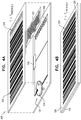
- FIGs. 7A and 7B are simplified respective exploded and assembled view illustrations of a quality indicator constructed and operative in accordance with a further preferred embodiment of the present invention, showing a first state thereof.
- a quality indicator 700 preferably operating as a visually sensible indicator of at least one parameter, which at least one parameter preferably includes at least one of temperature, time above or below a given temperature or temperature range, humidity and impact.
- Quality indicator 700 preferably includes electronic sensing circuitry 702 for sensing at least when the at least one parameter monitored by quality indicator 700 exceeds a predetermined threshold.
- electronic sensing circuitry 702 Upon exceedance of a predetermined threshold by quality indicator 700, electronic sensing circuitry 702 preferably provides a threshold exceedance output sensible as heat. The heat output of electronic circuitry 702 preferably causes an alteration in the visual appearance of quality indicator 700, thereby providing a visual indication of quality indicator 700 having exceeded the predetermined threshold, as will be detailed henceforth.
- electronic sensing circuity 702 is shown to include a battery 704 electrically connected to at least one electronic sensing element, here embodied as an electronic sensor 706.
- Sensor 706 may be any type of electronic component or routed arrangement of electronic components for electronically sensing exceedance of a predetermined threshold by the at least one parameter monitored by quality indicator 700.
- sensor 706 may be at least one of a heat sensor, time and temperature sensor, humidity sensor and impact sensor.
- Sensing circuitry 702 further preferably includes a first heat-generating filament 708 and a second heat-generating filament 709, which filaments 708, 709 are preferably respectively operative to provide outputs indicating exceedance of respective thresholds, as sensed by sensor circuitry 702, which outputs are sensible as heat.
- Battery 704, sensor 706 and filaments 708, 709 comprising circuitry 702 may be located on a supporting surface of quality indicator 700, such as a PCB layer 710. It is appreciated that circuitry 702 is shown in a highly simplified form in Fig. 7A and 7B and may include additional and/or alternative electronic components, as exemplified earlier with reference to Figs. 5A - 6 .
- circuitry 702 is disabled and hence sensor 706 irresponsive to changes in the parameter sensed thereby, prior to the activation of quality label 700.
- Circuitry 702 may be activated by way of an actuator element, here embodied as an actuation pull strip 712.
- Actuation pull strip 712 may be embodied as a displaceable pull strip for actuating circuitry 702 upon removal thereof.
- actuation pull strip 712 may be connected to battery 704, such that battery 704 is activated upon removal of pull strip 712.
- Quality indicator 700 further preferably includes a heat-responsive visually sensible display 720, responsive to the threshold exceedance outputs of filaments 708 and 709 of circuity 702.
- Heat-responsive visually sensible display 720 preferably employs a thermochromic material 722, such as a thermal paper 722 preferably located with respect to filaments 708 and 709 such that an appearance of thermal paper 722 is modified upon filament 708 and/or 709 becoming hot, following exceedance of the threshold.
- the change in appearance of thermal paper 722 thus provides a visually sensible indication of exceedance of a predetermined threshold by the at least one monitored parameter.
- thermochromic material 722 is preferably visible by way of a plurality of transparent windows 724 preferably formed in an exterior upper surface 726 of quality indicator 700.
- An appearance of transparent windows 724 is thereby preferably readably indicative of whether quality indicator 700 has exceeded a predetermined threshold, as will be detailed henceforth.
- Quality indicator 700 is preferably generally of type described, inter alia, in U.S. Pat. No. 8,091,776 of the applicant.
- heat-responsive visually sensible display 720 further preferably includes a multiplicity of barcodes 730 preferably formed on surface 726 such that plurality of transparent windows 724 are incorporated within multiplicity of barcodes 730.
- plurality of barcodes 730 is shown to include a first barcode 732 lying in a first tier I and incorporating a first portion of a first transparent window 734; a second barcode 736 lying in a second tier II and including a second portion of the first transparent window 734, a first portion of a second transparent window 738 and a first portion of third transparent window 740; a third barcode 742 lying in a third tier III and incorporating a second portion of second transparent window 738 and a second portion of third transparent window 740; and a fourth barcode 744 lying in a fourth tier IV and incorporating a third and final portion of third transparent window 740.
- first - third transparent windows 734, 738 and 740 are particularly preferred embodiments of plurality of transparent windows 724.
- quality indicator 700 there are preferably four operational states, namely a first operational state prior to activation of circuitry 702 in which first state a first one of multiplicity of barcodes 730 is machine-readable and the remaining ones of multiplicity of barcodes 730 are unreadable; a second operational state following activation of circuitry 702 and prior to exceedance of a first threshold by quality indicator 700, in which second state a second one of multiplicity of barcodes 730 is machine-readable and the remaining ones of multiplicity of barcodes 730 are unreadable; a third operational state following activation of circuitry 702 and upon exceedance of a first threshold by quality indicator 700, in which third state a third one of multiplicity of barcodes 730 is machine-readable and the remaining ones of multiplicity of barcodes 730 are unreadable and a fourth operational state following activation of circuitry 702 and upon exceedance of a second threshold, in which fourth state a fourth one of multiplicity of barcodes 730 is machine-readable and the remaining ones of multiplicity of bar
- quality indicator 700 and particularly the transition between the operational states thereof responsive to sensing of parameters monitored thereby will now be exemplified and further detailed with reference to Figs. 7A - 10B , with reference to which drawings quality indicator 700 is described as preferably operating as a visually sensible indicator of temperature and of temperature for a given time. However, it is appreciated that the following description also applies to the operation of quality indicator 700 as a visually sensible indicator of parameters other than temperature and time above or below a given temperature or temperature range, such as humidity and/or impact, with appropriate modifications as will be readily apparent to those skilled in the art.
- thermal paper 722 is preferably located interfacing multiplicity of barcodes 730 and activation pull strip 712.
- Thermal paper 722 preferably extends along some but not all of an anterior portion of surface 726 such that first transparent window 734 is backed by activation pull strip 712 and second and third transparent windows 738 and 740 are backed by thermal paper 722 when quality indicator 700 is in an assembled state, as shown in Fig. 7B .
- Activation pull strip 712 is preferably black, such that transparent window 734 is backed by a black surface formed by activation pull strip 712. As seen most clearly in Fig. 7B , transparent window 734 thus appears to be black, thereby rendering first barcoded region 732 of which blackened transparent window 734 forms a part, to be in a machine-readable state.
- Thermal paper 722 is preferably white, such that transparent windows 738 and 740 are backed by a white surface formed by thermal paper 722. As seen most clearly in Fig. 7B , transparent windows 738 and 740 thus appear to be white, thereby rendering second, third and fourth barcoded regions 736, 742 and 744 of which whitened transparent windows 738, 740 form a part to be unreadable.
- Figs. 8A and 8B illustrating the second operational state of quality indicator 700, activation pull strip 712 is removed, thereby activating circuitry 702 and hence quality indicator 700.
- electronic sensing circuitry 702 is preferably operative as electronic temperature sensing circuitry, for sensing when the temperature of quality indicator 700 lies within an acceptable temperature range, not less than a first predetermined low-temperature threshold T low threshold and not greater than a second predetermined high-temperature threshold T high threshold .
- sensor 706 is a temperature sensor which sensor 106 may be set to any desired low-temperature threshold such as, by way of example, 2°C as well as to any desired high-temperature and time threshold such as, by way of example, 8 °C for more than 12 hours.
- Sensor 706 is preferably operative to prevent current flow through filaments 708, 709 at temperatures within the acceptable temperature range, to allow current flow through filament 708 at temperatures less than or equal to the low-temperature threshold and to allow current flow through filament 709 at temperatures greater than the high-temperature threshold for a given threshold period of time.
- sensor 706 is illustrated herein as a single element, sensor 706 may alternatively be embodied as two or more individual sensors, individually respectively connected to first and second filaments 708 and 709 for control thereof.
- second filament 709 may be obviated and sensor 706 may operate as a low-temperature sensor only, which sensor may be set to a given low-temperature threshold so as to control current flow to first filament 708.
- exceedance of the high temperature threshold for a predetermined period of time by quality indicator 700 may be indicated by thermal paper 722 of display 720 independent of the output of circuitry 702, as will be further detailed henceforth with reference to Figs. 10A and 10B .
- quality indicator 700 lies within an acceptable temperature range, for example between 2 and 8 °C.
- current flow through electronic temperature sensor circuitry 702 is prevented by electronic sensor components 706, such that neither one of filaments 708 and 709 are heated.
- Thermal paper 722, located abutting filaments 708 and 709 and viewable through windows 738 and 740, is therefore not heated when quality indicator 700 is in this state and thus retains its original white appearance.
- Second and third transparent windows 738 and 740 thus remain white in this second operational state.
- first transparent window 734 is no longer backed by a black surface formed by activation pull strip 712 but rather by PCB layer 710, which PCB layer 710 is preferably white.
- First transparent window 734 therefore changes in appearance from black to white upon activation of quality indicator 700.
- first barcode 732 of which first transparent window 734 forms a part changes from the readable state shown in Fig. 7B to an unreadable state shown in Fig. 8B .
- second barcode 736 of which first transparent window 734 also forms a part changes from the unreadable state shown in Fig. 7B to a readable state shown in Fig. 8B .
- Figs. 9A and 9B illustrating a third operational state of quality indicator 700, upon quality indicator 700 falling to a temperature below T low threshold the exceedance of the low temperature threshold is preferably sensed by electric sensor circuitry 702, which circuitry 702 responsively allows current to flow to first filament 708.
- the resistance of sensor 706 may change upon temperature T falling below T low threshold , such that current is allowed to flow to first filament 708, thereby selectively heating first filament 708.
- the falling of indicator 700 to below a threshold temperature thereof is output in the form of heat, in this case, by way of the heating of filament 708.
- thermal paper 722 Upon first filament 708 becoming heated, filament 708 in turn heats thermal paper 722, which thermal paper 722 preferably undergoes a change in visual appearance thereupon.
- thermal paper 722 may darken in a first region 750 thereof, which region 750 is preferably immediately proximal to filament 708.
- second transparent window 738 of multiplicity of barcodes 730 is preferably backed by first region 750, such that second transparent window 738 changes in appearance from white to black upon region 750 darkening, as seen in Fig. 9B .
- the blackening of transparent window 738 does not affect first barcode 732 and fourth barcode 744, neither of which barcodes 732 and 744 second transparent window 738 forms a part. Both of first and fourth barcodes 732 and 744 therefore remain unreadable in this third operational state.
- second barcode 736 of which second transparent window 738 forms a part changes from the readable state shown in Fig. 8B to an unreadable state shown in Fig. 9B .
- third barcode 742 of which second transparent window 738 also forms a part changes from the unreadable state shown in Fig. 8B to a readable state shown in Fig. 9B .
- Figs. 10A and 10B illustrating the fourth operational state of quality indicator 700, in which fourth state quality indicator 700 rises to a temperature above T high threshold for longer than a given time, such as to above 8°C for more than 12 hours.
- the exceedance of the high temperature threshold for a given period of time is preferably sensed by electronic sensor circuitry 702, which circuitry 702 responsively allows current to flow to second filament 709, thereby heating second filament 709.
- thermal paper 722 Upon second filament 709 becoming heated, filament 709 in turn heats thermal paper 722, which thermal paper 722 preferably undergoes a change in visual appearance thereupon.
- thermal paper 722 may darken in a second region 752 thereof, which second region 752 is preferably immediately proximal to second filament 709.
- thermal paper 722 may alternatively darken due to an increase in temperature of indicator 700, independent of an output of electronic temperature sensing circuitry 702.
- second filament 709 may be obviated and thermal paper 722 may darken in a non-localized manner upon indicator 700 rising to above a given temperature.
- third transparent window 740 of multiplicity of barcodes 730 is preferably backed by second region 752, such that third transparent window 740 changes in appearance from white to black upon the darkening of region 752 or of larger regions of thermal paper 722, as seen in Fig. 10B .
- third barcode 742 of which third transparent window 740 forms a part preferably changes from the readable state shown in Fig. 9B to an unreadable state shown in Fig. 10B .
- fourth barcode 744 of which third transparent window 740 also forms a part changes from the unreadable state shown in Fig. 9B to a readable state shown in Fig. 10B .
- third transparent window 740 also forms a part of second barcode 736.
- Second barcode 736 preferably remains unreadable, notwithstanding the coloring of third transparent window 740.
- the fourth operational state of quality indicator 700 illustrated in Figs. 10A and 10B corresponds to the case in which quality indicator 700 exceeds a high temperature threshold for a given period of time following exceedance of a low temperature threshold, as illustrated in Figs. 9A and 9B .
- quality indicator 700 may exceed a high temperature threshold for a given period of time without prior exceedance of a low temperature threshold.
- region 752 of thermal paper 722 will darken due to the heating of filament 709 whereas region 750 of thermal paper 722 will remain blank.
- Third transparent window 740 backed by second region 752 of thermal paper 722 will therefore become opaque whereas second transparent window 738 will remain clear.
- third transparent window 740 which third transparent window 740 extends through second - fourth barcoded regions 736, 742 744, preferably causes fourth barcoded region 744 to change from an unreadable to a readable state, corresponding to the state of tier IV shown in Fig. 10B .
- the coloring of third transparent window 740 renders second and third barcode regions 736 and 742 unreadable, due to the coloring of a portion thereof. Additionally, first barcode 732 remains in an unreadable state.
- fourth barcode 744 is thus indicative of quality indicator 700 having exceeded a high temperature and time threshold, but is not indicative of whether quality indicator 700 also exceeded a low temperature threshold prior thereto.
- thermal paper 722 upon heating thereof is preferably irreversible, such that first and second regions 750 and 752 continue to appear opaque following exceedance of predetermined temperature thresholds as sensed and indicated by circuitry 702, independent of the present conditions to which quality indicator is subject.
- scanning of barcodes 730 of quality indicator 700 serves to provide a visually sensible indication of possible exposure of quality indicator 700 to unacceptable temperature conditions, irrespective of the present state of the quality indicator.
Landscapes
- Physics & Mathematics (AREA)
- General Physics & Mathematics (AREA)
- Life Sciences & Earth Sciences (AREA)
- Health & Medical Sciences (AREA)
- Nonlinear Science (AREA)
- Molecular Biology (AREA)
- Biophysics (AREA)
- Chemical & Material Sciences (AREA)
- Analytical Chemistry (AREA)
- Biochemistry (AREA)
- General Health & Medical Sciences (AREA)
- Immunology (AREA)
- Pathology (AREA)
- Measuring Temperature Or Quantity Of Heat (AREA)
Description
- The present invention relates generally to quality indicators and more particularly to electronic quality indicators.
- Various types of electronic quality indicators are known in the art. Specific reference is made in this respect to
US5451932 A ,US2007/0241916 A1 andUS8196821 B2 . - The present invention seeks to provide an electronic quality indicator for indicating exceedance of low temperature thresholds and other thresholds.
- There is thus provided in accordance with the present invention a visually sensible indicator according to claim 1. Advantageous modifications are defined in the dependent claims.
- The present invention will be understood and appreciated more fully from the following detailed description, taken in conjunction with the drawings in which:
-
Figs. 1A and 1B are simplified schematic respective exploded and assembled view illustrations of a quality indicator in a first temperature state thereof, constructed and operative in accordance with a preferred embodiment of the present invention; -
Figs. 2A and 2B are simplified schematic respective exploded and assembled view illustrations of a quality indicator of a type shown inFigs. 1A and 1B in a second temperature state thereof; -
Figs. 3A and 3B are simplified schematic respective exploded and assembled view illustrations of a quality indicator in a first temperature state thereof, constructed and operative in accordance with another preferred embodiment of the present invention; -
Figs. 4A and 4B are simplified schematic respective exploded and assembled view illustrations of a quality indicator of a type shown inFigs. 3A and 3B in a second temperature state thereof; -
Figs. 5A and 5B are simplified partially conceptual diagrams of electronic circuitry functionality, useful in a quality indicator of types shown inFigs. 1A - 4B ; -
Fig. 6 is a circuit diagram showing electronic components useful in a quality indicator of types shown inFigs. 1A - 4B ; -
Figs. 7A and 7B are simplified respective exploded and assembled view illustrations of a quality indicator constructed and operative in accordance with a further preferred embodiment of the present invention, showing a first state thereof; -
Figs. 8A and 8B are simplified respective exploded and assembled view illustrations of a quality indicator of the type shown inFigs. 7A and 7B , showing a second state thereof; -
Figs. 9A and 9B are simplified respective exploded and assembled view illustrations of a quality indicator of a type shown inFigs. 7A - 8B , showing a third state thereof; and -
Figs. 10A and 10B are simplified respective exploded and assembled view illustrations of a quality indicator of a type shown inFigs. 7A - 9B , showing a fourth state thereof. - Reference is now made to
Figs. 1A and 1B , which are simplified schematic respective exploded and assembled view illustrations of a quality indicator in a first temperature state thereof, constructed and operative in accordance with a preferred embodiment of the present invention. - As seen in
Figs. 1A and 1B , there is provided aquality indicator 100, preferably operating as a visually sensible indicator of at least one parameter, including at least one of temperature, time above or below a given temperature or temperature range, humidity and impact.Quality indicator 100 preferably includeselectronic sensing circuitry 102 for sensing at least when the at least one parameter monitored byquality indicator 100 exceeds a predetermined threshold. Upon exceedance of a predetermined threshold byquality indicator 100,electronic sensing circuitry 102 preferably provides a threshold exceedance output sensible as heat. The heat output ofelectronic circuitry 102 preferably causes an alteration in the visual appearance ofquality indicator 100, thereby providing a visual indication ofquality indicator 100 having exceeded the predetermined threshold, as will be detailed henceforth. - Here, by way of example,
electronic sensing circuity 102 is shown to include abattery 104 electrically connected to at least one electronic sensing element, here embodied as asensor 106.Sensing element 106 may be any type of electronic component or routed arrangement of components for electronically sensing exceedance of a predetermined threshold by the at least one parameter monitored byquality indicator 100. By way of example,sensor 106 may be at least one of a heat sensor, humidity sensor and/or impact sensor. -
Circuitry 102 preferably includes at least one heat-generating element, here embodied as a heat-generatingfilament 108, whichfilament 108 is preferably operative to provide an output indicating exceedance of the at least one threshold, as sensed bysensor 106, which output is sensible as heat.Battery 104,sensor 106 andfilament 108 comprisingcircuitry 102 may be located on a supporting surface ofquality indicator 100, such as a printed circuity board (PCB)layer 110. It is appreciated thatcircuitry 102 is shown in a highly simplified form inFig. 1A and 1B and may include additional and/or alternative electronic components. Further details concerning possible configurations ofcircuitry 102 will be provided henceforth with reference toFigs. 5A - 6 . -
Quality indicator 100 further preferably includes a heat-responsive visuallysensible display 120, responsive to the threshold exceedance output offilament 108 ofcircuity 102. Heat-responsive visuallysensible display 120 preferably employs athermochromic material 122, such as athermal paper 122, located in close proximity tofilament 108, such that an appearance ofthermal paper 122 is modified uponfilament 108 becoming hot, following exceedance of the threshold as sensed bysensor circuitry 102. The change in appearance ofthermal paper 122 thus provides a visually sensible indication of exceedance of a predetermined threshold by the at least one monitored parameter. - Here, by way of example, the change in appearance of
thermochromic material 122 may be viewed by a user ofquality indicator 100 through atransparent window 124 formed in an exteriorupper surface 126 ofquality indicator 100. An appearance oftransparent window 124 may thus be interpreted by a user ofquality indicator 100 as indicative of whetherquality indicator 100 has exceeded a predetermined threshold. Alternatively,thermal paper 122 may itself form an upper surface ofquality indicator 100, such that the change in appearance ofthermal paper 122 may be directly viewable by a user. In this case, additionalupper surface 126 includingtransparent window 124 may be obviated. - The modification of
thermal paper 122 upon heating thereof is preferably irreversible, such thatwindow 124 continues to appear colored following exceedance of a predetermined threshold as sensed and indicated bycircuitry 102, independent of the present conditions to which quality indicator is subject. As a result,quality indicator 100 provides a visually sensible indication of possible exposure to unacceptable conditions in the history ofquality indicator 100, irrespective of the present state of the quality indicator. - The operation of
quality indicator 100 will now be exemplified and further detailed with reference toFigs. 1A - 2B , with reference to whichquality indicator 100 is described as operating as a visually sensible indicator of temperature. However, it is appreciated that the following description also applies to the operation ofquality indicator 100 as a visually sensible indicator of parameters other than temperature, such as time or cumulative time above or below a given temperature or temperature range, humidity and/or impact, with appropriate modifications as will be readily apparent to those skilled in the art. - Referring now to
Figs. 1A and 1B ,quality indicator 100 is seen to be in a first temperature state, at a temperature T above a threshold temperature Tthreshold. In this embodiment ofquality indicator 100,quality indicator 100 is preferably operative as a low-temperature indicator, for indicating exceedance of a low-temperature threshold either by the environment within whichquality indicator 100 is located or by a temperature-sensitive item to whichquality indicator 100 may be affixed. Such items may include, by way of example, chemical or biological materials, food products and vaccines. - It is appreciated that
quality indicator 100 may alternatively operate as a high-temperature indicator for indicating exceedance of a high-temperature threshold, or as a 'time and temperature' indicator, for indicating exceedance of a high or low temperature threshold or temperature range for a cumulative predetermined threshold period of time. -
Electronic sensing circuitry 102 is here preferably operative as electronic temperature sensing circuitry, for sensing when the temperature ofquality indicator 100 exceeds a predetermined temperature threshold, and more particularly when the temperature ofquality indicator 100 falls below a predetermined temperature. For this purpose,sensor 106 operates a temperature sensor which may be set to any desired low temperature threshold such as, by way of example, 2°C. Sensor 106 is preferably operative to prevent current flow throughfilament 108 at temperatures above Threshold and to allow current flow throughfilament 108 at temperatures less than or equal to Tthreshold. Sensor 106 may be embodied, by way of example, as a positive temperature coefficient (PTC) thermistor, the resistance of which changes with falling temperature, examples of which are well known in the art. - In the first temperature state of
quality indicator 100 illustrated inFigs. 1A and 1B , whereinquality indicator 100 is at a temperature T> Tthreshold, current flow through electronictemperature sensor circuitry 102 is prevented, such thatfilament 108 is not heated.Thermal paper 122, located abuttingfilament 108 and viewable throughwindow 124, is therefore not heated byfilament 108 and thus retains its original appearance. By way of example,thermal paper 122 may be white when in an un-heated state.Window 124, backed bythermal paper 122, thus appears to be white or blank whenquality indicator 100 is at a temperature above the low-temperature threshold, as seen most clearly inFig. 1B .Window 124 in combination withthermal paper 122 thus provides a human-readable visually sensible indication ofquality indicator 100 being at a temperature above the low-temperature threshold. - Upon
quality indicator 100 falling to a temperature below Tthreshold, as seen inFigs. 2A and 2B , the exceedance of the low temperature threshold is preferably sensed byelectronic sensor circuit 102, whichelectronic sensor circuit 102 responsively allows current to flow tofilament 108. By way of example, the resistance ofsensor 106 may decrease upon temperature T falling below Tthreshold, such that current is allowed to flow tofilament 108, therebyheating filament 108. It is a particular feature of a preferred embodiment of the present invention that the falling ofindicator 100 to below a threshold temperature thereof is output in the form of heat, in this case, by way of the heating offilament 108. - It is appreciated that
sensor 106 is preferably of a type to substantially entirely prevent current flowing throughcircuity 102 at temperatures above Tthreshold and to permit current to flow throughcircuitry 102 at temperatures below Tthreshold in a discrete manner. Alternatively,sensor 106 may allow minimal current to flow throughcircuitry 102 at temperatures above Tthreshold, which minimal current is not sufficient to significantly heatfilament 108, and to allow increased current to flow throughcircuitry 102 at temperatures below Tthreshold, which increased current is sufficient to significantly heatfilament 108. - Upon
filament 108 becoming heated,filament 108 in turn heatsthermal paper 122, whichthermal paper 122 preferably undergoes a change in visual appearance thereupon.Thermal paper 122 may be in direct contact withfilament 108 or may be located in sufficiently close proximity to filament 108 so as to be heated thereby. By way of example, as seen most clearly inFig. 2A ,thermal paper 122 may darken upon being heated byfilament 108. More particularly,thermal paper 122 may change from white to black upon being heated, although it is appreciated alternative color changes inthermal paper 122 may also be possible. - As best appreciated from consideration of
Fig. 2B ,window 124, backed by darkenedthermal paper 122, thus changes in appearance from blank, as seen inFig. 1B , to dark or opaque whenquality indicator 100 falls to a temperature below the low-temperature threshold.Window 124 in combination withthermal paper 122 thus provides a human-readable visually sensible indication ofquality indicator 100 having fallen to a temperature below the low-temperature threshold whenquality indicator 100 is in the temperature state shown inFigs. 2A and 2B , due to the change in visual appearance thereof. - It is appreciated that the human-readable visually sensible indication of
quality indicator 100 having fallen below Tthreshold is presented inFigs. 1A - 2B in a highly simplified form, as a singlecolorable window 124. It will be apparent to those skilled in the art that the human-readable visually sensible indication may alternatively be embodied in more complex forms, including multiple transparent windows which may change appearance so as to bear a human-readable text message or symbol upon the thermochromic material therebeneath changing color due to heating. - Thus, by way of example,
colorable window 124 may be configured as multiple transparent windows in the form of text such as 'TOO COLD'. In the case thatupper surface 126 is white, the text will not be visible whenquality indicator 100 is at a temperature above the low-temperature threshold, due to the transparent windows being backed by a white surface formed bythermal paper 122 and thus not being visually detectable by a user ofquality indicator 100. Uponquality indicator 100 falling to a temperature below the low-temperature threshold andthermal paper 122 being heated byfilament 108,thermal paper 122 will change from white to black, thereby forming a black backing for the transparent windows inwhite surface 126. Consequently, the textual message 'TOO COLD' borne bywhite surface 126 will become visible and interpretable by a user. - It is further appreciated that the visually sensible indication of
quality indicator 100 having fallen to a temperature below Threshold is not limited to being a human-readable visually sensible indication and may additionally or alternatively be a machine-readable indication, as seen in the case of aquality indicator 300 illustrated inFigs. 3A - 4B . -
Quality indicator 300 may generally resemblequality indicator 100 in all relevant aspects thereof, with the exception of the configuration ofupper surface 126. Whereasupper surface 126 ofquality indicator 100 is illustrated as a generally blank surface, including a singletransparent window 124,upper surface 126 ofquality indicator 300 is preferably embodied as a barcoded surface, including a machine-readable barcode 302 comprising at least one transparent window, here embodied as a plurality oftransparent windows 324. It is appreciated thatbarcode 302 is not limited to being formed onupper surface 126 and may alternatively be located on other exterior surfaces ofquality indicator 300, in accordance with the design requirements thereof. - When
quality indicator 300 is at a temperature T> Threshold, as shown inFigs. 3A and 3B , current flow tofilament 108 is prevented byelectronic sensor circuitry 102, such thatfilament 108 is not heated.Thermal paper 122, located abuttingfilament 108, is therefore not heated byfilament 108 whenquality indicator 300 is in this state and thus retains its original appearance. By way of example,thermal paper 122 may be white when in an un-heated state.Windows 324, backed bythermal paper 122, thus appear to be white or blank whenquality indicator 300 is at a temperature above the low-temperature threshold, as seen most clearly inFig. 3B . - In this state,
barcode 302 appears to terminate at afinal indicium 326 andwindows 324 do not form a part ofbarcode 302.Barcode 302 is preferably machine- readable by a standard barcode scanner in this state, thereby providing a machine-readable visually sensible indication ofquality indicator 300 being at a temperature above the low-temperature threshold. Alternatively,barcode 302 may be unreadable in this state. - Upon
quality indicator 300 falling to a temperature below Tthreshold, as illustrated inFigs. 4A and 4B , the exceedance of the low temperature threshold is preferably sensed byelectronic sensor circuitry 102, whichcircuitry 102 responsively allows current to flow tofilament 108. By way of example, the resistance ofelectric sensor circuitry 102 may change upon temperature T falling below Tthreshold, such that current is allowed to flow tofilament 108, therebyheating filament 108. It is a particular feature of a preferred embodiment of the present invention that the falling ofindicator 300 to below a threshold temperature thereof is output in the form of heat, in this case, by way of the heating offilament 108. -
Heated filament 108 in turn preferably heatsthermal paper 122, whichthermal paper 122 preferably undergoes a change in visual appearance thereupon. By way of example, as seen most clearly inFig. 4A ,thermal paper 122 may darken upon being heated byfilament 108. More particularly,thermal paper 122 may change from white to black upon being heated.Thermal paper 122 may become substantially entirely black, as illustrated inFig. 4A . Alternatively,thermal paper 122 may undergo a localized change in visual appearance such as blackening only in a region immediately proximal tofilament 108. - As best appreciated from consideration of
Fig. 4B ,windows 324, backed by darkenedthermal paper 122, appear to be black whenquality indicator 300 is at a temperature below the low-temperature threshold, the blackened regions visible throughwindows 324 forming a part ofbarcode 302, beyondindicium 326. As a result of additional regions being appended tobarcode 302,barcode 302 preferably changes from the first state thereof illustrated inFig. 3B to a second state thereof, illustrated inFig. 4B . The change in state ofbarcode 302 may be from a first readable state ofFig. 3B to a second readable state ofFig. 4B , from a first readable state ofFig. 3B to an unreadable state ofFig. 4B or from an unreadable state ofFig. 3B to a readable state ofFig. 4B . The reading ofbarcode 302 by a conventional barcode scanner thus may provide an indication of possible exceedance of a low-temperature threshold byquality indicator 300. - It is appreciated that
barcode 302 may be any type of standard machine-readable barcode, as are well known in the art, such that the reading ofbarcode 302 by a barcode scanner may be used to indicate possible exposure ofquality indicator 300 or an item with whichquality indicator 300 is associated to a temperature below the low-temperature threshold. - It will be understood that
windows 324 are not limited to being located at a terminus ofbarcode 302 and may alternatively be positioned at other locations withinbarcode 302, such as at the start or in middle ofbarcode 302. It will be further understood thatwindows 324 are not limited to the particular configuration illustrated herein and may be formed as a variety of shapes and numbers of transparent windows, adapted to form part of a readable barcode or to render a barcode unreadable upon being colored. - Furthermore, it will be understood that
upper surface 126 in combination withwindows 324 may be configured such that prior to exceedance of a predetermined threshold byindicator 300,upper surface 126 includingwindows 324 is entirely blank and does not display a barcode. Upon exceedance of the threshold and consequent heating and darkening ofthermal paper 122, a readable barcode may become visible as a result of the coloring ofwindows 324. - Reference is now made to
Figs. 5A and 5B , which are simplified partially conceptual diagrams illustrating the functioning of electronic circuitry useful in a quality indicator of types shown inFigs. 1A - 4B . - As seen in
Figs. 5A and 5B , there is provided a partially conceptual diagram illustrating the functioning ofelectronic sensing circuitry 502, operative in a quality indicator of the present invention such asquality indicator electronic sensing circuitry 502 is representative of the functioning of highly simplifiedelectronic sensing circuitry 102 presented inFigs. 1A - 4B . -
Electronic sensing circuitry 502 preferably includes a power supply such as abattery 504 and preferably exhibits electronic switching functionality, here conceptually represented in the form of anelectronic switch 505. It is appreciated thatelectronic switch 505 does not necessarily correspond to a physical switch present incircuitry 502, but rather represents switching functionality performed bycircuitry 502. -
Electronic sensing circuitry 502 further preferably includes anelectronic sensing element 506 for controlling the switching functionality represented byswitch 505 and a heat-generating element, here shown in the form of a heat-generatingfilament 508.Circuitry 502 also may include a mechanism for preventing the overheating thereof, here shown in the form of afuse 509. - The operation of
circuitry 502 will be exemplified henceforth with reference toFigs. 5A and 5B in the context ofsensor 506 being a low-temperature sensor andcircuitry 502 hence operating as electronic temperature sensing circuitry within a low-temperature exceedance quality indicator, such asquality indicator sensor 506 may be any type of electronic sensor component or components for sensing exceedance of a predetermined threshold by a particular parameter to be monitored by a quality indicator of the present invention, which parameter may be at least one of temperature, humidity, time above or below a given temperature or temperature range, impact or other parameters. - Turning now to
Fig. 5A ,circuitry 502 is seen to be at a temperature T > Threshold, where Tthreshold is a low-temperature threshold of a quality indicator with whichcircuitry 502 is preferably associated. The state ofcircuitry 502 as represented inFig. 5A thus corresponds to the state ofquality indicator 100 inFigs. 1A and 1B and to the state ofquality indicator 300 inFigs. 3A and 3B . The temperature ofcircuitry 502 is preferably sensed by low-temperature sensor 506. In this state,circuitry 502 prevents current flow tofilament 508, thus operating as an open circuit, as represented by the open state ofconceptual switch 505. - Upon the temperature falling to below Tthreshold, as shown in
Fig. 5B ,circuitry 502 allows current to flow tofilament 508, thus operating as a closed circuit, as represented by the closed state ofconceptual switch 505. This corresponds to the state ofquality indicator 100 inFigs. 2A and 2B and the state ofquality indicator 300 inFigs. 4A and 4B .Filament 508 heats up due to the flow of current therethrough, thereby providing a low-temperature threshold exceedance output in the form of heat. Overheating offilament 508 is preferably prevented by the presence offuse 509. Fuse 509 is preferably configured to melt or otherwise form an open-circuit at a predetermined current level and/or time, sufficient to allow a change in visual appearance of the thermochromic material to occur prior thereto. - Reference is now made to
Fig. 6 , which is a circuit diagram showing electronic components useful in a quality indicator of types shown inFigs. 1A - 4B . It is appreciated that in contrast toFigs. 5A and 5B , which drawings are partially conceptual diagrams primarily illustrating functionality ofelectronic circuitry 502,Fig. 6 illustrates a physical arrangement of electronic components found to be useful in a quality indicator of the present invention. - As seen in
Fig. 6 ,electronic sensing circuitry 602 may include abattery 604, atemperature sensor 606 and afuse 607. In this embodiment, fuse 607 preferably acts both as a heat-generating element and as a heat-regulating element for preventing overheating, such that the need for two separate elements respectively individually carrying out these functions is obviated. - Upon exceedance of a predetermined threshold temperature being sensed by
temperature sensor 606, an electrical property oftemperature sensor 606, such as resistance, may change, thereby allowing current to flow throughcircuitry 602. Fuse 607 is consequently heated and may subsequently melt or otherwise form an open circuit at a given current level. It is appreciated thatcircuitry 602 may also include other electrical components, generally designated by thereference number 610, to ensure optimum functioning thereof. - Reference is now made to
Figs. 7A and 7B , which are simplified respective exploded and assembled view illustrations of a quality indicator constructed and operative in accordance with a further preferred embodiment of the present invention, showing a first state thereof. - As seen in
Figs. 7A and 7B , there is provided aquality indicator 700, preferably operating as a visually sensible indicator of at least one parameter, which at least one parameter preferably includes at least one of temperature, time above or below a given temperature or temperature range, humidity and impact.Quality indicator 700 preferably includeselectronic sensing circuitry 702 for sensing at least when the at least one parameter monitored byquality indicator 700 exceeds a predetermined threshold. Upon exceedance of a predetermined threshold byquality indicator 700,electronic sensing circuitry 702 preferably provides a threshold exceedance output sensible as heat. The heat output ofelectronic circuitry 702 preferably causes an alteration in the visual appearance ofquality indicator 700, thereby providing a visual indication ofquality indicator 700 having exceeded the predetermined threshold, as will be detailed henceforth. - Here, by way of example,
electronic sensing circuity 702 is shown to include abattery 704 electrically connected to at least one electronic sensing element, here embodied as anelectronic sensor 706.Sensor 706 may be any type of electronic component or routed arrangement of electronic components for electronically sensing exceedance of a predetermined threshold by the at least one parameter monitored byquality indicator 700. By way of example,sensor 706 may be at least one of a heat sensor, time and temperature sensor, humidity sensor and impact sensor. -
Sensing circuitry 702 further preferably includes a first heat-generatingfilament 708 and a second heat-generatingfilament 709, whichfilaments sensor circuitry 702, which outputs are sensible as heat.Battery 704,sensor 706 andfilaments circuitry 702 may be located on a supporting surface ofquality indicator 700, such as aPCB layer 710. It is appreciated thatcircuitry 702 is shown in a highly simplified form inFig. 7A and 7B and may include additional and/or alternative electronic components, as exemplified earlier with reference toFigs. 5A - 6 . - It is a particular feature of this embodiment of the present invention that
electronic sensing circuitry 702 is disabled and hencesensor 706 irresponsive to changes in the parameter sensed thereby, prior to the activation ofquality label 700.Circuitry 702 may be activated by way of an actuator element, here embodied as anactuation pull strip 712.Actuation pull strip 712 may be embodied as a displaceable pull strip for actuatingcircuitry 702 upon removal thereof. By way of example,actuation pull strip 712 may be connected tobattery 704, such thatbattery 704 is activated upon removal ofpull strip 712. -
Quality indicator 700 further preferably includes a heat-responsive visuallysensible display 720, responsive to the threshold exceedance outputs offilaments circuity 702. Heat-responsive visuallysensible display 720 preferably employs athermochromic material 722, such as athermal paper 722 preferably located with respect tofilaments thermal paper 722 is modified uponfilament 708 and/or 709 becoming hot, following exceedance of the threshold. The change in appearance ofthermal paper 722 thus provides a visually sensible indication of exceedance of a predetermined threshold by the at least one monitored parameter. - Here, by way of example, the change in appearance of
thermochromic material 722 is preferably visible by way of a plurality of transparent windows 724 preferably formed in an exteriorupper surface 726 ofquality indicator 700. An appearance of transparent windows 724 is thereby preferably readably indicative of whetherquality indicator 700 has exceeded a predetermined threshold, as will be detailed henceforth. -
Quality indicator 700 is preferably generally of type described, inter alia, inU.S. Pat. No. 8,091,776 of the applicant. Thus, heat-responsive visuallysensible display 720 further preferably includes a multiplicity ofbarcodes 730 preferably formed onsurface 726 such that plurality of transparent windows 724 are incorporated within multiplicity ofbarcodes 730. - Here, by way of example, plurality of
barcodes 730 is shown to include afirst barcode 732 lying in a first tier I and incorporating a first portion of a firsttransparent window 734; asecond barcode 736 lying in a second tier II and including a second portion of the firsttransparent window 734, a first portion of a secondtransparent window 738 and a first portion of thirdtransparent window 740; athird barcode 742 lying in a third tier III and incorporating a second portion of secondtransparent window 738 and a second portion of thirdtransparent window 740; and afourth barcode 744 lying in a fourth tier IV and incorporating a third and final portion of thirdtransparent window 740. It is appreciated that first - thirdtransparent windows - In the illustrated embodiment of
quality indicator 700, there are preferably four operational states, namely a first operational state prior to activation ofcircuitry 702 in which first state a first one of multiplicity ofbarcodes 730 is machine-readable and the remaining ones of multiplicity ofbarcodes 730 are unreadable; a second operational state following activation ofcircuitry 702 and prior to exceedance of a first threshold byquality indicator 700, in which second state a second one of multiplicity ofbarcodes 730 is machine-readable and the remaining ones of multiplicity ofbarcodes 730 are unreadable; a third operational state following activation ofcircuitry 702 and upon exceedance of a first threshold byquality indicator 700, in which third state a third one of multiplicity ofbarcodes 730 is machine-readable and the remaining ones of multiplicity ofbarcodes 730 are unreadable and a fourth operational state following activation ofcircuitry 702 and upon exceedance of a second threshold, in which fourth state a fourth one of multiplicity ofbarcodes 730 is machine-readable and the remaining ones of multiplicity ofbarcodes 730 are unreadable. - The operation of
quality indicator 700 and particularly the transition between the operational states thereof responsive to sensing of parameters monitored thereby will now be exemplified and further detailed with reference toFigs. 7A - 10B , with reference to whichdrawings quality indicator 700 is described as preferably operating as a visually sensible indicator of temperature and of temperature for a given time. However, it is appreciated that the following description also applies to the operation ofquality indicator 700 as a visually sensible indicator of parameters other than temperature and time above or below a given temperature or temperature range, such as humidity and/or impact, with appropriate modifications as will be readily apparent to those skilled in the art. - In the first operational state of
quality indicator 700 illustrated inFigs. 7A and 7B ,activation pull strip 712 has not been removed fromquality indicator 700 andcircuitry 702 is therefore inactive and irresponsive to changes in temperature.Thermal paper 722 is preferably located interfacing multiplicity ofbarcodes 730 andactivation pull strip 712.Thermal paper 722 preferably extends along some but not all of an anterior portion ofsurface 726 such that firsttransparent window 734 is backed byactivation pull strip 712 and second and thirdtransparent windows thermal paper 722 whenquality indicator 700 is in an assembled state, as shown inFig. 7B .Activation pull strip 712 is preferably black, such thattransparent window 734 is backed by a black surface formed byactivation pull strip 712. As seen most clearly inFig. 7B ,transparent window 734 thus appears to be black, thereby rendering firstbarcoded region 732 of which blackenedtransparent window 734 forms a part, to be in a machine-readable state. -
Thermal paper 722 is preferably white, such thattransparent windows thermal paper 722. As seen most clearly inFig. 7B ,transparent windows barcoded regions transparent windows - It is understood that in the first operational state of quality indicator 700 a single barcode, namely
barcode 732, is machine readable whereas all of the remaining barcodes of multiplicity ofbarcodes 730 are unreadable. The scanning of multiplicity ofbarcodes 730 by a conventional barcode scanner therefore may be used to confirm thatquality indicator 700 has not yet been activated. It will be appreciated that this would be the case irrespective of the temperature ofquality indicator 700, since in this firstoperational state circuitry 702 has not yet been switched on and is thus insensitive to changes in temperature. - Turning now to
Figs. 8A and 8B , illustrating the second operational state ofquality indicator 700,activation pull strip 712 is removed, thereby activatingcircuitry 702 and hencequality indicator 700. In this embodiment ofquality indicator 700,electronic sensing circuitry 702 is preferably operative as electronic temperature sensing circuitry, for sensing when the temperature ofquality indicator 700 lies within an acceptable temperature range, not less than a first predetermined low-temperature threshold Tlow threshold and not greater than a second predetermined high-temperature threshold Thigh threshold. For this purpose,sensor 706 is a temperature sensor whichsensor 106 may be set to any desired low-temperature threshold such as, by way of example, 2°C as well as to any desired high-temperature and time threshold such as, by way of example, 8 °C for more than 12 hours. -
Sensor 706 is preferably operative to prevent current flow throughfilaments filament 708 at temperatures less than or equal to the low-temperature threshold and to allow current flow throughfilament 709 at temperatures greater than the high-temperature threshold for a given threshold period of time. - It is appreciated that although
sensor 706 is illustrated herein as a single element,sensor 706 may alternatively be embodied as two or more individual sensors, individually respectively connected to first andsecond filaments - In a further alternative embodiment of the present invention,
second filament 709 may be obviated andsensor 706 may operate as a low-temperature sensor only, which sensor may be set to a given low-temperature threshold so as to control current flow tofirst filament 708. In this embodiment, exceedance of the high temperature threshold for a predetermined period of time byquality indicator 700 may be indicated bythermal paper 722 ofdisplay 720 independent of the output ofcircuitry 702, as will be further detailed henceforth with reference toFigs. 10A and 10B . - In the second operational state of
quality indicator 700 illustrated inFigs. 8A and 8B ,quality indicator 700 lies within an acceptable temperature range, for example between 2 and 8 °C. In this state, current flow through electronictemperature sensor circuitry 702 is prevented byelectronic sensor components 706, such that neither one offilaments Thermal paper 722, located abuttingfilaments windows quality indicator 700 is in this state and thus retains its original white appearance. Second and thirdtransparent windows - However, due to the removal of
activation pull strip 712, firsttransparent window 734 is no longer backed by a black surface formed byactivation pull strip 712 but rather byPCB layer 710, whichPCB layer 710 is preferably white. Firsttransparent window 734 therefore changes in appearance from black to white upon activation ofquality indicator 700. As a result,first barcode 732 of which firsttransparent window 734 forms a part changes from the readable state shown inFig. 7B to an unreadable state shown inFig. 8B . Preferably simultaneously,second barcode 736 of which firsttransparent window 734 also forms a part changes from the unreadable state shown inFig. 7B to a readable state shown inFig. 8B . - It is understood that in the second operational state of quality indicator 700 a single barcode, namely
second barcode 736 of tier II, is machine readable whereas all of the remaining barcodes of multiplicity ofbarcodes 730 are unreadable. Multiplicity ofbarcodes 730, including plurality of transparent windows 724 backed bythermal paper 722, therefore forms a heat-responsive visually sensible display, the scanning of which display by a conventional barcode scanner may be used to indicate thatquality indicator 700 has been activated and lies within an acceptable temperature range. - Turning now to
Figs. 9A and 9B , illustrating a third operational state ofquality indicator 700, uponquality indicator 700 falling to a temperature below Tlow threshold the exceedance of the low temperature threshold is preferably sensed byelectric sensor circuitry 702, whichcircuitry 702 responsively allows current to flow tofirst filament 708. By way of example, the resistance ofsensor 706 may change upon temperature T falling below Tlow threshold, such that current is allowed to flow tofirst filament 708, thereby selectively heatingfirst filament 708. It is a particular feature of a preferred embodiment of the present invention that the falling ofindicator 700 to below a threshold temperature thereof is output in the form of heat, in this case, by way of the heating offilament 708. - Upon
first filament 708 becoming heated,filament 708 in turn heatsthermal paper 722, whichthermal paper 722 preferably undergoes a change in visual appearance thereupon. By way of example, as seen most clearly inFig. 9A ,thermal paper 722 may darken in afirst region 750 thereof, whichregion 750 is preferably immediately proximal tofilament 708. - As best appreciated from consideration of
Fig. 9A , secondtransparent window 738 of multiplicity ofbarcodes 730 is preferably backed byfirst region 750, such that secondtransparent window 738 changes in appearance from white to black uponregion 750 darkening, as seen inFig. 9B . The blackening oftransparent window 738 does not affectfirst barcode 732 andfourth barcode 744, neither of which barcodes 732 and 744 secondtransparent window 738 forms a part. Both of first andfourth barcodes second barcode 736 of which secondtransparent window 738 forms a part changes from the readable state shown inFig. 8B to an unreadable state shown inFig. 9B . Preferably simultaneously,third barcode 742 of which secondtransparent window 738 also forms a part changes from the unreadable state shown inFig. 8B to a readable state shown inFig. 9B . - It is understood that in the third operational state of quality indicator 700 a single barcode, namely
third barcode 742, is machine readable whereas all of the remaining barcodes of multiplicity ofbarcodes 730 are unreadable. Multiplicity ofbarcodes 730, including plurality of transparent windows 724 backed bythermal paper 722, therefore forms a heat-responsive visually sensible display, the scanning of which by a conventional barcode scanner may be used to indicate thatquality indicator 700 has been activated and has exceeded a low-temperature threshold. - Reference is now made to
Figs. 10A and 10B illustrating the fourth operational state ofquality indicator 700, in which fourthstate quality indicator 700 rises to a temperature above Thigh threshold for longer than a given time, such as to above 8°C for more than 12 hours. In this state, the exceedance of the high temperature threshold for a given period of time is preferably sensed byelectronic sensor circuitry 702, whichcircuitry 702 responsively allows current to flow tosecond filament 709, thereby heatingsecond filament 709. - Upon
second filament 709 becoming heated,filament 709 in turn heatsthermal paper 722, whichthermal paper 722 preferably undergoes a change in visual appearance thereupon. By way of example, as seen most clearly inFig. 10A ,thermal paper 722 may darken in asecond region 752 thereof, whichsecond region 752 is preferably immediately proximal tosecond filament 709. - It is appreciated that
thermal paper 722 may alternatively darken due to an increase in temperature ofindicator 700, independent of an output of electronictemperature sensing circuitry 702. In this case,second filament 709 may be obviated andthermal paper 722 may darken in a non-localized manner uponindicator 700 rising to above a given temperature. - As best appreciated from consideration of
Fig. 10A , thirdtransparent window 740 of multiplicity ofbarcodes 730 is preferably backed bysecond region 752, such that thirdtransparent window 740 changes in appearance from white to black upon the darkening ofregion 752 or of larger regions ofthermal paper 722, as seen inFig. 10B . - The blackening of
transparent window 740 does not affectfirst barcode 732, whichfirst barcode 732 therefore remains unreadable in this fourth operational state. However,third barcode 742 of which thirdtransparent window 740 forms a part preferably changes from the readable state shown inFig. 9B to an unreadable state shown inFig. 10B . Preferably simultaneously,fourth barcode 744 of which thirdtransparent window 740 also forms a part changes from the unreadable state shown inFig. 9B to a readable state shown inFig. 10B . It is appreciated that thirdtransparent window 740 also forms a part ofsecond barcode 736.Second barcode 736 preferably remains unreadable, notwithstanding the coloring of thirdtransparent window 740. - It is appreciated that the fourth operational state of
quality indicator 700 illustrated inFigs. 10A and 10B corresponds to the case in whichquality indicator 700 exceeds a high temperature threshold for a given period of time following exceedance of a low temperature threshold, as illustrated inFigs. 9A and 9B . However, it will be understood that an alternative scenario is also possible, in whichquality indicator 700 may exceed a high temperature threshold for a given period of time without prior exceedance of a low temperature threshold. - In the case that
quality indicator 700 exceeds a high temperature threshold for a given period of time without prior exceedance of a low temperature threshold,region 752 ofthermal paper 722 will darken due to the heating offilament 709 whereasregion 750 ofthermal paper 722 will remain blank. Thirdtransparent window 740 backed bysecond region 752 ofthermal paper 722 will therefore become opaque whereas secondtransparent window 738 will remain clear. - The coloring of third
transparent window 740, which thirdtransparent window 740 extends through second - fourthbarcoded regions barcoded region 744 to change from an unreadable to a readable state, corresponding to the state of tier IV shown inFig. 10B . Preferably simultaneously, the coloring of thirdtransparent window 740 renders second andthird barcode regions first barcode 732 remains in an unreadable state. - It is understood that in the fourth operational state of
quality indicator 700, upon exceedance of a high temperature threshold for a given period of time, a single barcode, namelyfourth barcode 744 is machine readable whereas all of the remaining barcodes of multiplicity ofbarcodes 730 are preferably unreadable. - It is appreciated that this is the case irrespective of whether or not
quality indicator 700 exceeded a low temperature threshold prior to the exceedance of the high temperature and time threshold, as illustrated inFig. 10A and 10B . The readability offourth barcode 744 is thus indicative ofquality indicator 700 having exceeded a high temperature and time threshold, but is not indicative of whetherquality indicator 700 also exceeded a low temperature threshold prior thereto. - The modification of
thermal paper 722 upon heating thereof is preferably irreversible, such that first andsecond regions circuitry 702, independent of the present conditions to which quality indicator is subject. As a result, the scanning ofbarcodes 730 ofquality indicator 700 serves to provide a visually sensible indication of possible exposure ofquality indicator 700 to unacceptable temperature conditions, irrespective of the present state of the quality indicator.
Claims (13)
- A visually sensible indicator (300, 700) of at least one parameter including at least one of temperature, time above or below a given temperature range, humidity and impact, said indicator comprising:a barcode (302, 730); anda heat-responsive visually sensible display (122, 324, 720) for providing a visually sensible indication indicating that said at least one parameter has exceeded a predetermined threshold, said visually sensible indication being machine readable and at least a part of the barcode (302, 730);characterized by:
an electronic sensing circuitry (102, 502, 702) sensing at least when said at least one parameter exceeds said predetermined threshold and providing a threshold exceedance output which is sensible as heat, with said heat-responsive visually sensible display (122, 324, 720) being responsive to said threshold exceedance output. - A visually sensible indicator (300, 700) of at least one parameter according to claim 1, and wherein said visually sensible indication is human readable.
- A visually sensible indicator (300, 700) of at least one parameter according to claim 1, and wherein said visually sensible indication is rendering a barcode unreadable.
- A visually sensible indicator (300, 700) of at least one parameter according to any of the preceding claims and wherein said exceedance of said predetermined threshold is falling below a given temperature.
- A visually sensible indicator (300, 700) of at least one parameter according to any of the preceding claims and wherein said exceedance of said predetermined threshold is rising above a given temperature.
- A visually sensible indicator (300, 700) of at least one parameter according to any of the preceding claims and wherein said exceedance of one of said at least one predetermined threshold is falling below a given temperature and exceedance of another of said at least one predetermined threshold is rising above a given temperature.
- A visually sensible indicator (300, 700) of at least one parameter according to claim 6 wherein rising above a given temperature is indicated by said heat-responsive visually sensible display (122, 324, 720) independent of an output of said electronic sensing circuitry (102, 502, 702).
- A visually sensible indicator (300, 700) of at least one parameter according to any of the preceding claims and wherein said heat-responsive visually sensible display (122, 324, 720) employs a thermochromic material.
- A visually sensible indicator (300, 700) of at least one parameter according to any of the preceding claims, wherein said electronic sensing circuitry (502) comprises a mechanism (509) operative to prevent overheating thereof.
- A visually sensible indicator (300, 700) of at least one parameter according to claim 1, wherein said electronic sensing circuitry (102, 502, 702) is not responsive to changes in said at least one parameter prior to activation thereof.
- A visually sensible indicator (300, 700) of at least one parameter according to claim 10, and also comprising an actuator element (505) for activating said electronic sensing circuitry (502).
- A visually sensible indicator (700) of at least one parameter according to claim 10 or claim 11, wherein said visually sensible display (720) comprises a multiplicity of barcodes (730), a first one (732) of said multiplicity of barcodes (730) being machine readable prior to said activation.
- A visually sensible indicator (700) of at least one parameter according to claim 12, wherein said first one (732) of said multiplicity of barcodes (730) becomes unreadable following said activation and a second one (736) of said multiplicity of barcodes (730) becomes machine readable following said activation.
Applications Claiming Priority (2)
| Application Number | Priority Date | Filing Date | Title |
|---|---|---|---|
| US201562189367P | 2015-07-07 | 2015-07-07 | |
| PCT/IL2016/050727 WO2017006326A1 (en) | 2015-07-07 | 2016-07-07 | Electronic quality indicator |
Publications (3)
| Publication Number | Publication Date |
|---|---|
| EP3320315A1 EP3320315A1 (en) | 2018-05-16 |
| EP3320315A4 EP3320315A4 (en) | 2019-03-13 |
| EP3320315B1 true EP3320315B1 (en) | 2020-03-04 |
Family
ID=57684929
Family Applications (1)
| Application Number | Title | Priority Date | Filing Date |
|---|---|---|---|
| EP16820959.1A Active EP3320315B1 (en) | 2015-07-07 | 2016-07-07 | Electronic quality indicator |
Country Status (6)
| Country | Link |
|---|---|
| US (4) | US10697837B2 (en) |
| EP (1) | EP3320315B1 (en) |
| JP (1) | JP6898298B2 (en) |
| CN (1) | CN107709946B (en) |
| CA (1) | CA2991275A1 (en) |
| WO (1) | WO2017006326A1 (en) |
Families Citing this family (11)
| Publication number | Priority date | Publication date | Assignee | Title |
|---|---|---|---|---|
| WO2007129316A2 (en) | 2006-05-07 | 2007-11-15 | Varcode Ltd. | A system and method for improved quality management in a product logistic chain |
| US7562811B2 (en) | 2007-01-18 | 2009-07-21 | Varcode Ltd. | System and method for improved quality management in a product logistic chain |
| WO2008135962A2 (en) | 2007-05-06 | 2008-11-13 | Varcode Ltd. | A system and method for quality management utilizing barcode indicators |
| US8500014B2 (en) | 2007-11-14 | 2013-08-06 | Varcode Ltd. | System and method for quality management utilizing barcode indicators |
| US11704526B2 (en) | 2008-06-10 | 2023-07-18 | Varcode Ltd. | Barcoded indicators for quality management |
| US8807422B2 (en) | 2012-10-22 | 2014-08-19 | Varcode Ltd. | Tamper-proof quality management barcode indicators |
| CN107615027B (en) | 2015-05-18 | 2020-03-27 | 发可有限公司 | Thermochromic ink labels for activatable quality labels |
| CA2991275A1 (en) | 2015-07-07 | 2017-01-12 | Varcode Ltd. | Electronic quality indicator |
| FR3073299B1 (en) * | 2017-11-07 | 2021-04-09 | Newsteo | DEVICE FOR RECORDING DATA OF ENVIRONMENTAL CONDITIONS SUCH AS TEMPERATURE |
| US11263504B2 (en) * | 2018-02-01 | 2022-03-01 | Shockwatch, Inc. | Temperature indicator |
| US20230114227A1 (en) * | 2021-10-11 | 2023-04-13 | Temptime Corporation | Semi-irreversible temperature exposure sensor customizable by thermal printer |
Family Cites Families (200)
| Publication number | Priority date | Publication date | Assignee | Title |
|---|---|---|---|---|
| US4057029A (en) | 1976-03-08 | 1977-11-08 | Infratab Corporation | Time-temperature indicator |
| US4059407A (en) | 1976-04-14 | 1977-11-22 | Becton, Dickinson And Company | Disposable chemical indicators |
| USRE31586E (en) | 1977-01-21 | 1984-05-15 | Altex Scientific, Inc. | Liquid chromatography pump |
| JPS5759293A (en) | 1980-09-26 | 1982-04-09 | Hitachi Ltd | Bar code |
| US4674065A (en) | 1982-04-30 | 1987-06-16 | International Business Machines Corporation | System for detecting and correcting contextual errors in a text processing system |
| JPH07104904B2 (en) | 1986-10-08 | 1995-11-13 | 日本電装株式会社 | Bar code reader |
| JPS63118894A (en) | 1986-11-06 | 1988-05-23 | Nippon Denso Co Ltd | Bar code label |
| US5146405A (en) | 1988-02-05 | 1992-09-08 | At&T Bell Laboratories | Methods for part-of-speech determination and usage |
| US5600119A (en) | 1988-10-21 | 1997-02-04 | Symbol Technologies, Inc. | Dual line laser scanning system and scanning method for reading multidimensional bar codes |
| US5053339A (en) | 1988-11-03 | 1991-10-01 | J P Labs Inc. | Color changing device for monitoring shelf-life of perishable products |
| CA1329263C (en) | 1989-03-01 | 1994-05-03 | Mark Krichever | Bar code scanner |
| JPH0353281A (en) | 1989-07-21 | 1991-03-07 | Nakanishi Kinzoku Kogyo Kk | Temperature display label and abnormal overheating control device using the label |
| US5254473A (en) | 1990-03-16 | 1993-10-19 | Jp Laboratories | Solid state device for monitoring integral values of time and temperature of storage of perishables |
| JPH0567253A (en) | 1990-10-29 | 1993-03-19 | Fujita Corp | Bar code |
| JPH056470A (en) | 1990-10-29 | 1993-01-14 | Fujita Corp | Bar code |
| US5202677A (en) | 1991-01-31 | 1993-04-13 | Crystal Images, Inc. | Display apparatus using thermochromic material |
| US5085802A (en) | 1991-01-31 | 1992-02-04 | Oscar Mayer Foods Corporation | Time temperature indicator with distinct end point |
| US5369577A (en) | 1991-02-01 | 1994-11-29 | Wang Laboratories, Inc. | Text searching system |
| US5084143A (en) | 1991-03-19 | 1992-01-28 | Alcan International Limited | Color change devices incorporating areas of contrasting appearance |
| JPH0519695A (en) | 1991-07-17 | 1993-01-29 | Matsushita Electric Ind Co Ltd | Merchandise label and pos system |
| US5451932A (en) * | 1993-02-25 | 1995-09-19 | Maytag Corporation | Method and means for indicating an appliance condition |
| FR2704947B1 (en) | 1993-05-06 | 1995-07-28 | Lepeudry | COLORIMETRIC ASSAY PROCEDURE FOR ENALDEHYDES AS LIPID PEROXIDATION INDICES, SUBSTITUTED INDOLES FOR USE IN THIS PROCESS AND THEIR PREPARATION. |
| US7157048B2 (en) | 1993-05-19 | 2007-01-02 | Sira Technologies, Inc. | Detection of contaminants |
| US6190610B1 (en) | 1993-05-19 | 2001-02-20 | California South Pacific Investors | Detection of contaminants in food |
| US20030113228A1 (en) | 1993-05-19 | 2003-06-19 | Goldsmith Robert M. | Contamination detection system |
| JP3406605B2 (en) | 1993-05-19 | 2003-05-12 | カリフォルニア・サウス・パシフィック・インベスターズ | Means of detecting contaminants in food |
| CA2185455A1 (en) | 1994-04-22 | 1995-11-02 | David Brian Edwards | Security label |
| SE513456C2 (en) | 1994-05-10 | 2000-09-18 | Telia Ab | Method and device for speech to text conversion |
| US5485372A (en) | 1994-06-01 | 1996-01-16 | Mitsubishi Electric Research Laboratories, Inc. | System for underlying spelling recovery |
| JP3260979B2 (en) | 1994-07-15 | 2002-02-25 | 株式会社リコー | Character recognition method |
| US5499597A (en) | 1994-11-01 | 1996-03-19 | Kronberg; James W. | Optical temperature indicator using thermochromic semiconductors |
| US5617488A (en) | 1995-02-01 | 1997-04-01 | The Research Foundation Of State University Of New York | Relaxation word recognizer |
| US5634195A (en) | 1995-03-27 | 1997-05-27 | Telefonaktiebolaget Lm Ericsson | System and method for setting of output power parameters in a cellular mobile telecommunication system |
| US5659771A (en) | 1995-05-19 | 1997-08-19 | Mitsubishi Electric Information Technology Center America, Inc. | System for spelling correction in which the context of a target word in a sentence is utilized to determine which of several possible words was intended |
| US5828991A (en) | 1995-06-30 | 1998-10-27 | The Research Foundation Of The State University Of New York | Sentence reconstruction using word ambiguity resolution |
| AU6849196A (en) | 1995-08-16 | 1997-03-19 | Syracuse University | Multilingual document retrieval system and method using semantic vector matching |
| US5822728A (en) | 1995-09-08 | 1998-10-13 | Matsushita Electric Industrial Co., Ltd. | Multistage word recognizer based on reliably detected phoneme similarity regions |
| US6173261B1 (en) | 1998-09-30 | 2001-01-09 | At&T Corp | Grammar fragment acquisition using syntactic and semantic clustering |
| CA2166847C (en) | 1995-09-19 | 2000-09-05 | Frederick Davis | Multilayered dispersed thermochromic liquid crystal |
| KR100551001B1 (en) | 1995-09-22 | 2006-07-06 | 퍼시픽 커뮤니케이션 싸이언스 인코포레이티드 | A cellular communication system with multiple code rates |
| WO1997017694A1 (en) | 1995-11-04 | 1997-05-15 | International Business Machines Corporation | Method and apparatus for adapting the language model's size in a speech recognition system |
| US6009400A (en) | 1996-03-05 | 1999-12-28 | Blackman; Seymour | Method and arrangement for alerting customers from purchasing perished items using bar codes with changeable properties when subjected to factors causing perishability |
| US6098034A (en) | 1996-03-18 | 2000-08-01 | Expert Ease Development, Ltd. | Method for standardizing phrasing in a document |
| US5776371A (en) | 1996-04-16 | 1998-07-07 | Avery Dennison Corporation | Conductive composition for fuse state indicator |
| US5882116A (en) | 1996-04-25 | 1999-03-16 | Backus; Alan | Tamper indication device |
| US6085206A (en) | 1996-06-20 | 2000-07-04 | Microsoft Corporation | Method and system for verifying accuracy of spelling and grammatical composition of a document |
| US5956739A (en) | 1996-06-25 | 1999-09-21 | Mitsubishi Electric Information Technology Center America, Inc. | System for text correction adaptive to the text being corrected |
| USRE39266E1 (en) | 1996-07-01 | 2006-09-05 | Dr. Reddy's Laboratories, Limited | Heterocyclic compounds, process for their preparation and pharmaceutical compositions containing them and their use in the treatment of diabetes and related diseases |
| US5907839A (en) | 1996-07-03 | 1999-05-25 | Yeda Reseach And Development, Co., Ltd. | Algorithm for context sensitive spelling correction |
| ATE297552T1 (en) | 1996-09-30 | 2005-06-15 | California South Pacific Investors | DETECTION OF CONTAMINANTS IN FOOD |
| US6495368B1 (en) | 1996-11-05 | 2002-12-17 | Grouptek, Inc. | Methods and devices for detecting microbial spoilage in food products |
| US6335922B1 (en) | 1997-02-11 | 2002-01-01 | Qualcomm Incorporated | Method and apparatus for forward link rate scheduling |
| US5902982A (en) | 1997-04-04 | 1999-05-11 | National Medical Review Office Inc. | Changeable machine readable assaying indicia |
| US5929422A (en) | 1997-04-04 | 1999-07-27 | National Medical Review Office Inc. | On-site Machine readable assaying system |
| USRE39226E1 (en) | 1997-04-04 | 2006-08-08 | Escreen, Inc. | Changeable machine readable assaying indicia |
| SE9701612D0 (en) | 1997-04-29 | 1997-04-29 | Johan Asplund | Smartcard and method for its manufacture |
| US6181909B1 (en) | 1997-07-22 | 2001-01-30 | Educational Testing Service | System and method for computer-based automatic essay scoring |
| US5841285A (en) * | 1997-07-25 | 1998-11-24 | Eveready Battery Company, Inc. | Temperature-compensated thermochromic battery tester |
| WO1999030268A1 (en) | 1997-12-06 | 1999-06-17 | Jon Cameron | Thermochromic bar code |
| US6154722A (en) | 1997-12-18 | 2000-11-28 | Apple Computer, Inc. | Method and apparatus for a speech recognition system language model that integrates a finite state grammar probability and an N-gram probability |
| GB9801137D0 (en) | 1998-01-20 | 1998-03-18 | Eastman Kodak Co | Time-temparature indicator devices |
| FI108181B (en) | 1998-02-13 | 2001-11-30 | Nokia Mobile Phones Ltd | A power control method |
| US6424983B1 (en) | 1998-05-26 | 2002-07-23 | Global Information Research And Technologies, Llc | Spelling and grammar checking system |
| US7072826B1 (en) | 1998-06-04 | 2006-07-04 | Matsushita Electric Industrial Co., Ltd. | Language conversion rule preparing device, language conversion device and program recording medium |
| DE19842404A1 (en) | 1998-09-16 | 2000-03-23 | Philips Corp Intellectual Pty | Procedure for estimating probabilities of occurrence for language vocabulary elements |
| WO2000019410A1 (en) | 1998-09-30 | 2000-04-06 | Lernout & Hauspie Speech Products N.V. | Graphic user interface for navigation in speech recognition system grammars |
| US6917291B2 (en) | 1998-10-26 | 2005-07-12 | Identec Solutions Inc. | Interrogation, monitoring and data exchange using RFID tags |
| US6317707B1 (en) | 1998-12-07 | 2001-11-13 | At&T Corp. | Automatic clustering of tokens from a corpus for grammar acquisition |
| ATE443946T1 (en) | 1999-05-27 | 2009-10-15 | Tegic Communications Inc | KEYBOARD SYSTEM WITH AUTOMATIC CORRECTION |
| US7030863B2 (en) | 2000-05-26 | 2006-04-18 | America Online, Incorporated | Virtual keyboard system with automatic correction |
| AU5451800A (en) | 1999-05-28 | 2000-12-18 | Sehda, Inc. | Phrase-based dialogue modeling with particular application to creating recognition grammars for voice-controlled user interfaces |
| US20020032564A1 (en) | 2000-04-19 | 2002-03-14 | Farzad Ehsani | Phrase-based dialogue modeling with particular application to creating a recognition grammar for a voice-controlled user interface |
| ZA200201566B (en) | 1999-09-15 | 2003-05-26 | Edward A Devlin | Method and system for redeeming products marketing rebates. |
| US7165019B1 (en) | 1999-11-05 | 2007-01-16 | Microsoft Corporation | Language input architecture for converting one text form to another text form with modeless entry |
| US6848080B1 (en) | 1999-11-05 | 2005-01-25 | Microsoft Corporation | Language input architecture for converting one text form to another text form with tolerance to spelling, typographical, and conversion errors |
| US6544925B1 (en) | 2000-03-02 | 2003-04-08 | Lifelines Technology, Inc. | Activatable time-temperature indicator system |
| TW472232B (en) | 2000-08-11 | 2002-01-11 | Ind Tech Res Inst | Probability-base fault-tolerance natural language understanding method |
| US7254773B2 (en) | 2000-12-29 | 2007-08-07 | International Business Machines Corporation | Automated spell analysis |
| US6951596B2 (en) | 2002-01-18 | 2005-10-04 | Avery Dennison Corporation | RFID label technique |
| US7269545B2 (en) | 2001-03-30 | 2007-09-11 | Nec Laboratories America, Inc. | Method for retrieving answers from an information retrieval system |
| US6758397B2 (en) | 2001-03-31 | 2004-07-06 | Koninklijke Philips Electronics N.V. | Machine readable label reader system for articles with changeable status |
| US7117144B2 (en) | 2001-03-31 | 2006-10-03 | Microsoft Corporation | Spell checking for text input via reduced keypad keys |
| FR2824978B1 (en) | 2001-05-15 | 2003-09-19 | Wavecom Sa | DEVICE AND METHOD FOR PROCESSING AN AUDIO SIGNAL |
| CN1391180A (en) | 2001-06-11 | 2003-01-15 | 国际商业机器公司 | Auxiliary foreign language writing methods and tools |
| GB2376335B (en) | 2001-06-28 | 2003-07-23 | Vox Generation Ltd | Address recognition using an automatic speech recogniser |
| US7295965B2 (en) | 2001-06-29 | 2007-11-13 | Honeywell International Inc. | Method and apparatus for determining a measure of similarity between natural language sentences |
| US7003444B2 (en) | 2001-07-12 | 2006-02-21 | Microsoft Corporation | Method and apparatus for improved grammar checking using a stochastic parser |
| FR2829854B1 (en) * | 2001-09-17 | 2005-05-13 | Renaud Vaillant | PROCESS FOR CONTROLLING A PRODUCT WHOSE CONSERVATION IMPLEMENTS A COLD CHAIN |
| US7296019B1 (en) | 2001-10-23 | 2007-11-13 | Microsoft Corporation | System and methods for providing runtime spelling analysis and correction |
| US20030097243A1 (en) | 2001-10-23 | 2003-05-22 | Mays Thomas Gilmore | Method and system for operating a hydrocarbon production facility |
| NO316480B1 (en) | 2001-11-15 | 2004-01-26 | Forinnova As | Method and system for textual examination and discovery |
| JP2003203210A (en) | 2002-01-07 | 2003-07-18 | Canon Electronics Inc | Bar code |
| AUPR986502A0 (en) * | 2002-01-09 | 2002-01-31 | Helmer, Jonathon Charles | Identification system |
| US7969306B2 (en) | 2002-01-11 | 2011-06-28 | Sap Aktiengesellschaft | Context-aware and real-time item tracking system architecture and scenarios |
| US6801245B2 (en) | 2002-01-18 | 2004-10-05 | Imageid Ltd. | Method for automatic identification and data capture |
| AU2003267953A1 (en) | 2002-03-26 | 2003-12-22 | University Of Southern California | Statistical machine translation using a large monlingual corpus |
| US20030187632A1 (en) | 2002-04-02 | 2003-10-02 | Menich Barry J. | Multimedia conferencing system |
| US7020338B1 (en) | 2002-04-08 | 2006-03-28 | The United States Of America As Represented By The National Security Agency | Method of identifying script of line of text |
| US20030204569A1 (en) | 2002-04-29 | 2003-10-30 | Michael R. Andrews | Method and apparatus for filtering e-mail infected with a previously unidentified computer virus |
| US20030210249A1 (en) | 2002-05-08 | 2003-11-13 | Simske Steven J. | System and method of automatic data checking and correction |
| US20040002849A1 (en) | 2002-06-28 | 2004-01-01 | Ming Zhou | System and method for automatic retrieval of example sentences based upon weighted editing distance |
| US7386442B2 (en) | 2002-07-03 | 2008-06-10 | Word Data Corp. | Code, system and method for representing a natural-language text in a form suitable for text manipulation |
| US20040030540A1 (en) | 2002-08-07 | 2004-02-12 | Joel Ovil | Method and apparatus for language processing |
| CA2499268C (en) | 2002-09-27 | 2012-07-10 | Callminer, Inc. | Software for statistical analysis of speech |
| US7057495B2 (en) | 2002-10-17 | 2006-06-06 | Paksense, Llc | Perishable product electronic label including time and temperature measurement |
| EP1560009A4 (en) | 2002-10-24 | 2007-08-15 | Chromic Co Ltd | Temperature indicating display device |
| US7092567B2 (en) | 2002-11-04 | 2006-08-15 | Matsushita Electric Industrial Co., Ltd. | Post-processing system and method for correcting machine recognized text |
| US6982640B2 (en) | 2002-11-21 | 2006-01-03 | Kimberly-Clark Worldwide, Inc. | RFID system and method for tracking food freshness |
| SE524448C2 (en) | 2002-12-03 | 2004-08-10 | Henry Norrby | Packaging for storing goods in a preservative state, method for labeling such packaging, and temperature indicator for the packaging |
| JP2004184920A (en) | 2002-12-06 | 2004-07-02 | Mitsubishi Paper Mills Ltd | Temperature indicating label |
| FR2848688A1 (en) | 2002-12-17 | 2004-06-18 | France Telecom | Text language identifying device for linguistic analysis of text, has analyzing unit to analyze chain characters of words extracted from one text, where each chain is completed so that each time chains are found in word |
| US6698272B1 (en) | 2002-12-30 | 2004-03-02 | International Business Machines Corporation | Device for indicating exposure to an impact, adverse temperature and/or humidity |
| WO2004092697A1 (en) | 2003-04-16 | 2004-10-28 | NYGÅRDH, Mats | A temperature indicator, a package for goods and a method of monitoring the freshness of goods kept in packages |
| US20050043940A1 (en) | 2003-08-20 | 2005-02-24 | Marvin Elder | Preparing a data source for a natural language query |
| US20050053900A1 (en) | 2003-09-05 | 2005-03-10 | Steven Kaufmann | Method of teaching a foreign language to a student providing measurement in a context based learning system |
| US7475015B2 (en) | 2003-09-05 | 2009-01-06 | International Business Machines Corporation | Semantic language modeling and confidence measurement |
| US20050120002A1 (en) | 2003-10-02 | 2005-06-02 | Hassan Behbehani | Automated text generation process |
| US7017806B2 (en) | 2003-10-22 | 2006-03-28 | Peterson Stanley K | Method of selecting and storing airline ticket data |
| US7447627B2 (en) | 2003-10-23 | 2008-11-04 | Microsoft Corporation | Compound word breaker and spell checker |
| US7720675B2 (en) | 2003-10-27 | 2010-05-18 | Educational Testing Service | Method and system for determining text coherence |
| US7813916B2 (en) | 2003-11-18 | 2010-10-12 | University Of Utah | Acquisition and application of contextual role knowledge for coreference resolution |
| US20070141544A1 (en) | 2003-11-28 | 2007-06-21 | Katsuaki Nakane | Apparatus for grading and evaluating compositional essays |
| EP1700248A4 (en) | 2003-12-08 | 2008-06-04 | Int Barcode Corp | Method for identifying and authenticating goods using codes, barcodes and radio frequency identification |
| US7166345B2 (en) | 2004-03-08 | 2007-01-23 | Tri-State Hospital Supply Corporation | Destructible privacy label |
| US7478033B2 (en) | 2004-03-16 | 2009-01-13 | Google Inc. | Systems and methods for translating Chinese pinyin to Chinese characters |
| US7254774B2 (en) | 2004-03-16 | 2007-08-07 | Microsoft Corporation | Systems and methods for improved spell checking |
| US7779354B2 (en) | 2004-05-13 | 2010-08-17 | International Business Machines Corporation | Method and data processing system for recognizing and correcting dyslexia-related spelling errors |
| WO2006009727A2 (en) | 2004-06-16 | 2006-01-26 | Harcourt Assessment, Inc. | Language disorder assessment and associated methods |
| US8321786B2 (en) | 2004-06-17 | 2012-11-27 | Apple Inc. | Routine and interface for correcting electronic text |
| JP2006018782A (en) | 2004-06-30 | 2006-01-19 | Koichi Debuchi | Two-dimensional bar code having visual information |
| CN101019157A (en) * | 2004-08-10 | 2007-08-15 | 英特利马兹有限责任公司 | Electronic floor display with alerting |
| US7387457B2 (en) | 2004-08-13 | 2008-06-17 | 5 Examples, Inc. | One-row keyboard and approximate typing |
| US20060048055A1 (en) | 2004-08-25 | 2006-03-02 | Jun Wu | Fault-tolerant romanized input method for non-roman characters |
| WO2006032025A1 (en) | 2004-09-13 | 2006-03-23 | Food Quality Sensor International, Inc. | Food quality indicator |
| WO2006031199A1 (en) | 2004-09-17 | 2006-03-23 | Alex Poh Teck Choong | System and method for batch conversion of rfid tag to rfid label |
| US7392187B2 (en) | 2004-09-20 | 2008-06-24 | Educational Testing Service | Method and system for the automatic generation of speech features for scoring high entropy speech |
| US20060081711A1 (en) | 2004-09-30 | 2006-04-20 | Junxiang Zhao | Color-identifying system for colored barcode and a method thereof |
| US7401293B2 (en) | 2004-11-19 | 2008-07-15 | Spelldoctor, Llc | System and method for teaching spelling |
| EP1817691A4 (en) | 2004-12-01 | 2009-08-19 | Whitesmoke Inc | System and method for automatic enrichment of documents |
| US7457808B2 (en) | 2004-12-17 | 2008-11-25 | Xerox Corporation | Method and apparatus for explaining categorization decisions |
| US7630980B2 (en) | 2005-01-21 | 2009-12-08 | Prashant Parikh | Automatic dynamic contextual data entry completion system |
| US7805300B2 (en) | 2005-03-21 | 2010-09-28 | At&T Intellectual Property Ii, L.P. | Apparatus and method for analysis of language model changes |
| EP1712216B1 (en) | 2005-04-12 | 2008-05-14 | Straumann Holding AG | packaging for a dental product and its appropriate label |
| US7584093B2 (en) | 2005-04-25 | 2009-09-01 | Microsoft Corporation | Method and system for generating spelling suggestions |
| US8650087B2 (en) | 2005-06-06 | 2014-02-11 | Fugaku Tsuun Co., Ltd. | Product evaluation information delivering system and product evaluation information delivering method |
| US8131746B2 (en) | 2005-06-23 | 2012-03-06 | International Business Machines Corporation | Dynamic language checking |
| US20070067177A1 (en) | 2005-08-31 | 2007-03-22 | Temptime Corporation | Quality assurance system and methods of use |
| DE102005051470A1 (en) | 2005-10-21 | 2007-04-26 | Bizerba Gmbh & Co. Kg | Activating device for activatable indicators for labeling, device for providing activated indicators and methods for activating indicators |
| US20070094024A1 (en) | 2005-10-22 | 2007-04-26 | International Business Machines Corporation | System and method for improving text input in a shorthand-on-keyboard interface |
| JP2007121017A (en) | 2005-10-26 | 2007-05-17 | Jiikuesuto:Kk | Temperature indicating label changing with passage of time |
| JP2007122509A (en) | 2005-10-28 | 2007-05-17 | Rozetta Corp | Device, method and program for determining naturalness of phrase sequence |
| US7747427B2 (en) | 2005-12-05 | 2010-06-29 | Electronics And Telecommunications Research Institute | Apparatus and method for automatic translation customized for documents in restrictive domain |
| US8608477B2 (en) | 2006-04-06 | 2013-12-17 | Vantage Technologies Knowledge Assessment, L.L.C. | Selective writing assessment with tutoring |
| US7528737B2 (en) | 2006-04-10 | 2009-05-05 | Rosemount Inc. | Temperature responsive indicators for process control instruments |
| US7562811B2 (en) | 2007-01-18 | 2009-07-21 | Varcode Ltd. | System and method for improved quality management in a product logistic chain |
| WO2007129316A2 (en) | 2006-05-07 | 2007-11-15 | Varcode Ltd. | A system and method for improved quality management in a product logistic chain |
| US20070265831A1 (en) | 2006-05-09 | 2007-11-15 | Itai Dinur | System-Level Correction Service |
| US7558725B2 (en) | 2006-05-23 | 2009-07-07 | Lexisnexis, A Division Of Reed Elsevier Inc. | Method and apparatus for multilingual spelling corrections |
| DE102006034810A1 (en) | 2006-07-27 | 2008-01-31 | Bizerba Gmbh & Co. Kg | Method for checking a time and / or temperature-sensitive indicator |
| US20080043804A1 (en) | 2006-08-16 | 2008-02-21 | Goldsmith Robert M | Identification and condition detection system |
| US8271266B2 (en) | 2006-08-31 | 2012-09-18 | Waggner Edstrom Worldwide, Inc. | Media content assessment and control systems |
| US7689408B2 (en) | 2006-09-01 | 2010-03-30 | Microsoft Corporation | Identifying language of origin for words using estimates of normalized appearance frequency |
| JP2008089673A (en) | 2006-09-29 | 2008-04-17 | Sato Corp | Thermally active label |
| US7590626B2 (en) | 2006-10-30 | 2009-09-15 | Microsoft Corporation | Distributional similarity-based models for query correction |
| WO2008053466A2 (en) | 2006-10-30 | 2008-05-08 | Cellesense Technologies Ltd. | Context sensitive, error correction of short text messages |
| US7702680B2 (en) | 2006-11-02 | 2010-04-20 | Microsoft Corporation | Document summarization by maximizing informative content words |
| US20100020970A1 (en) | 2006-11-13 | 2010-01-28 | Xu Liu | System And Method For Camera Imaging Data Channel |
| US20080154600A1 (en) | 2006-12-21 | 2008-06-26 | Nokia Corporation | System, Method, Apparatus and Computer Program Product for Providing Dynamic Vocabulary Prediction for Speech Recognition |
| EP1936606B1 (en) | 2006-12-21 | 2011-10-05 | Harman Becker Automotive Systems GmbH | Multi-stage speech recognition |
| US7957955B2 (en) | 2007-01-05 | 2011-06-07 | Apple Inc. | Method and system for providing word recommendations for text input |
| US9465791B2 (en) | 2007-02-09 | 2016-10-11 | International Business Machines Corporation | Method and apparatus for automatic detection of spelling errors in one or more documents |
| US7991609B2 (en) | 2007-02-28 | 2011-08-02 | Microsoft Corporation | Web-based proofing and usage guidance |
| US7600912B2 (en) | 2007-03-20 | 2009-10-13 | Xerox Corporation | Temperature sensitive label for detecting temperature changes to a temperature sensitive item |
| US8005664B2 (en) | 2007-04-30 | 2011-08-23 | Tachyon Technologies Pvt. Ltd. | System, method to generate transliteration and method for generating decision tree to obtain transliteration |
| WO2008135962A2 (en) | 2007-05-06 | 2008-11-13 | Varcode Ltd. | A system and method for quality management utilizing barcode indicators |
| WO2009016631A2 (en) | 2007-08-01 | 2009-02-05 | Ginger Software, Inc. | Automatic context sensitive language correction and enhancement using an internet corpus |
| WO2010013228A1 (en) | 2008-07-31 | 2010-02-04 | Ginger Software, Inc. | Automatic context sensitive language generation, correction and enhancement using an internet corpus |
| US7917355B2 (en) | 2007-08-23 | 2011-03-29 | Google Inc. | Word detection |
| US20120239834A1 (en) | 2007-08-31 | 2012-09-20 | Google Inc. | Automatic correction of user input using transliteration |
| WO2009040790A2 (en) | 2007-09-24 | 2009-04-02 | Robert Iakobashvili | Method and system for spell checking |
| US8500014B2 (en) | 2007-11-14 | 2013-08-06 | Varcode Ltd. | System and method for quality management utilizing barcode indicators |
| US8085285B2 (en) * | 2007-12-19 | 2011-12-27 | Applied Minds, Llc | Thermal marking system |
| US20090198671A1 (en) | 2008-02-05 | 2009-08-06 | Yahoo! Inc. | System and method for generating subphrase queries |
| US8706474B2 (en) | 2008-02-23 | 2014-04-22 | Fair Isaac Corporation | Translation of entity names based on source document publication date, and frequency and co-occurrence of the entity names |
| KR101491581B1 (en) | 2008-04-07 | 2015-02-24 | 삼성전자주식회사 | Correction System for spelling error and method thereof |
| JP5474933B2 (en) | 2008-04-16 | 2014-04-16 | ジンジャー ソフトウェア、インコーポレイティッド | A system for teaching writing based on the user's past writing |
| WO2009130692A2 (en) | 2008-04-22 | 2009-10-29 | Robert Iakobashvili | Method and system for user-interactive iterative spell checking |
| WO2010134061A1 (en) | 2009-05-20 | 2010-11-25 | Varcode Ltd. | Barcoded indicators for quality management |
| US8473278B2 (en) | 2008-07-24 | 2013-06-25 | Educational Testing Service | Systems and methods for identifying collocation errors in text |
| US20100269454A1 (en) | 2009-04-22 | 2010-10-28 | Brad Reddersen | Systems and methods for activating thermochromic ink labels |
| US8868402B2 (en) | 2009-12-30 | 2014-10-21 | Google Inc. | Construction of text classifiers |
| US9070269B2 (en) | 2010-11-23 | 2015-06-30 | Battle Sports Science, Llc | Impact sensing device and helmet incorporating the same |
| FR2986324A1 (en) | 2012-01-30 | 2013-08-02 | Gem Innov | RESPECT INDICATOR OF A TEMPERATURE RANGE |
| US8807422B2 (en) | 2012-10-22 | 2014-08-19 | Varcode Ltd. | Tamper-proof quality management barcode indicators |
| EP2810717B1 (en) | 2013-06-06 | 2018-10-17 | F. Hoffmann-La Roche AG | Acceleration sensitive indicator |
| CA2866025A1 (en) | 2013-10-03 | 2015-04-03 | Quiang Song | Sensor unit for a functional electrical stimulation (fes) orthotic system |
| GB201322460D0 (en) * | 2013-12-18 | 2014-02-05 | Chesapeake Ltd | Temperature monitor |
| CN204176727U (en) * | 2014-10-03 | 2015-02-25 | 北京中科联众科技股份有限公司 | A kind of infrared induction heater of changeable colour |
| CN107615027B (en) | 2015-05-18 | 2020-03-27 | 发可有限公司 | Thermochromic ink labels for activatable quality labels |
| CA2991275A1 (en) | 2015-07-07 | 2017-01-12 | Varcode Ltd. | Electronic quality indicator |
-
2016
- 2016-07-07 CA CA2991275A patent/CA2991275A1/en active Pending
- 2016-07-07 CN CN201680039584.0A patent/CN107709946B/en active Active
- 2016-07-07 EP EP16820959.1A patent/EP3320315B1/en active Active
- 2016-07-07 US US15/742,181 patent/US10697837B2/en active Active
- 2016-07-07 WO PCT/IL2016/050727 patent/WO2017006326A1/en active Application Filing
- 2016-07-07 JP JP2018500482A patent/JP6898298B2/en active Active
-
2020
- 2020-06-08 US US16/895,001 patent/US11009406B2/en active Active
-
2021
- 2021-05-07 US US17/314,295 patent/US11614370B2/en active Active
-
2023
- 2023-03-13 US US18/120,736 patent/US11920985B2/en active Active
Non-Patent Citations (1)
| Title |
|---|
| None * |
Also Published As
| Publication number | Publication date |
|---|---|
| CA2991275A1 (en) | 2017-01-12 |
| CN107709946B (en) | 2022-05-10 |
| US10697837B2 (en) | 2020-06-30 |
| US20180195908A1 (en) | 2018-07-12 |
| US11920985B2 (en) | 2024-03-05 |
| US11009406B2 (en) | 2021-05-18 |
| EP3320315A1 (en) | 2018-05-16 |
| CN107709946A (en) | 2018-02-16 |
| US20200370966A1 (en) | 2020-11-26 |
| WO2017006326A1 (en) | 2017-01-12 |
| JP2018519530A (en) | 2018-07-19 |
| EP3320315A4 (en) | 2019-03-13 |
| JP6898298B2 (en) | 2021-07-07 |
| US20230280216A1 (en) | 2023-09-07 |
| US11614370B2 (en) | 2023-03-28 |
| US20210333159A1 (en) | 2021-10-28 |
Similar Documents
| Publication | Publication Date | Title |
|---|---|---|
| US11920985B2 (en) | Electronic quality indicator | |
| EP3298367B1 (en) | Thermochromic ink indicia for activatable quality labels | |
| US5451932A (en) | Method and means for indicating an appliance condition | |
| EP1576913B1 (en) | Electric heater with current sensor | |
| ES2215826T3 (en) | TEMPERATURE INDICATOR DEVICE. | |
| US7654733B2 (en) | Method and device for identifying a temperature sensor connected to a control unit | |
| FI117878B3 (en) | Alarm device for a kitchen range or range hood | |
| US8299405B2 (en) | Household appliance for heating liquid | |
| KR100781579B1 (en) | Controller of bed-temperature | |
| JP2005063881A (en) | Induction heating cooking device | |
| JP2008071771A5 (en) | ||
| EP1255477B1 (en) | Indicator for liquid heating appliances | |
| JP2003505164A5 (en) | ||
| KR101031787B1 (en) | Apparatus for controlling overheating proctection of electric cooktop and method thereof | |
| JP7349497B2 (en) | Food cooking containers and their respective improved heat warning transfer devices | |
| CN108652415A (en) | Electric cooker and its interior pot detection method | |
| DE19646959A1 (en) | Glass ceramic panel for gas-burning cooker | |
| GB2407478A (en) | Electronically-controlled domestic kettle | |
| KR200246278Y1 (en) | Electric iron | |
| CN115019438A (en) | Cabinet equipment | |
| JPH04122217A (en) | Heating cooker | |
| JPH0420308A (en) | Heating cooker | |
| JPH07235247A (en) | Temperature control device | |
| JPH03202019A (en) | Rice cooking and warming jar | |
| KR19990027310U (en) | Microwave overheating device |
Legal Events
| Date | Code | Title | Description |
|---|---|---|---|
| STAA | Information on the status of an ep patent application or granted ep patent |
Free format text: STATUS: THE INTERNATIONAL PUBLICATION HAS BEEN MADE |
|
| PUAI | Public reference made under article 153(3) epc to a published international application that has entered the european phase |
Free format text: ORIGINAL CODE: 0009012 |
|
| STAA | Information on the status of an ep patent application or granted ep patent |
Free format text: STATUS: REQUEST FOR EXAMINATION WAS MADE |
|
| 17P | Request for examination filed |
Effective date: 20180205 |
|
| AK | Designated contracting states |
Kind code of ref document: A1 Designated state(s): AL AT BE BG CH CY CZ DE DK EE ES FI FR GB GR HR HU IE IS IT LI LT LU LV MC MK MT NL NO PL PT RO RS SE SI SK SM TR |
|
| AX | Request for extension of the european patent |
Extension state: BA ME |
|
| DAV | Request for validation of the european patent (deleted) | ||
| DAX | Request for extension of the european patent (deleted) | ||
| A4 | Supplementary search report drawn up and despatched |
Effective date: 20190211 |
|
| RIC1 | Information provided on ipc code assigned before grant |
Ipc: G01D 7/00 20060101ALI20190205BHEP Ipc: G01N 31/22 20060101ALI20190205BHEP Ipc: G01K 1/02 20060101ALI20190205BHEP Ipc: G01K 3/04 20060101AFI20190205BHEP Ipc: G01K 3/00 20060101ALI20190205BHEP Ipc: G06K 19/06 20060101ALI20190205BHEP Ipc: G01K 11/12 20060101ALI20190205BHEP |
|
| REG | Reference to a national code |
Ref country code: DE Ref legal event code: R079 Ref document number: 602016031217 Country of ref document: DE Free format text: PREVIOUS MAIN CLASS: G01K0011120000 Ipc: G01K0003040000 |
|
| GRAP | Despatch of communication of intention to grant a patent |
Free format text: ORIGINAL CODE: EPIDOSNIGR1 |
|
| STAA | Information on the status of an ep patent application or granted ep patent |
Free format text: STATUS: GRANT OF PATENT IS INTENDED |
|
| RIC1 | Information provided on ipc code assigned before grant |
Ipc: G01K 3/00 20060101ALI20190906BHEP Ipc: G06K 19/06 20060101ALI20190906BHEP Ipc: G01N 31/22 20060101ALI20190906BHEP Ipc: G01K 1/02 20060101ALI20190906BHEP Ipc: G01D 7/00 20060101ALI20190906BHEP Ipc: G01K 11/12 20060101ALI20190906BHEP Ipc: G01K 3/04 20060101AFI20190906BHEP |
|
| INTG | Intention to grant announced |
Effective date: 20190925 |
|
| GRAS | Grant fee paid |
Free format text: ORIGINAL CODE: EPIDOSNIGR3 |
|
| GRAA | (expected) grant |
Free format text: ORIGINAL CODE: 0009210 |
|
| STAA | Information on the status of an ep patent application or granted ep patent |
Free format text: STATUS: THE PATENT HAS BEEN GRANTED |
|
| AK | Designated contracting states |
Kind code of ref document: B1 Designated state(s): AL AT BE BG CH CY CZ DE DK EE ES FI FR GB GR HR HU IE IS IT LI LT LU LV MC MK MT NL NO PL PT RO RS SE SI SK SM TR |
|
| REG | Reference to a national code |
Ref country code: GB Ref legal event code: FG4D |
|
| REG | Reference to a national code |
Ref country code: CH Ref legal event code: EP |
|
| REG | Reference to a national code |
Ref country code: AT Ref legal event code: REF Ref document number: 1240939 Country of ref document: AT Kind code of ref document: T Effective date: 20200315 |
|
| REG | Reference to a national code |
Ref country code: DE Ref legal event code: R096 Ref document number: 602016031217 Country of ref document: DE |
|
| REG | Reference to a national code |
Ref country code: IE Ref legal event code: FG4D |
|
| REG | Reference to a national code |
Ref country code: CH Ref legal event code: NV Representative=s name: NOVAGRAAF INTERNATIONAL SA, CH |
|
| PG25 | Lapsed in a contracting state [announced via postgrant information from national office to epo] |
Ref country code: FI Free format text: LAPSE BECAUSE OF FAILURE TO SUBMIT A TRANSLATION OF THE DESCRIPTION OR TO PAY THE FEE WITHIN THE PRESCRIBED TIME-LIMIT Effective date: 20200304 Ref country code: NO Free format text: LAPSE BECAUSE OF FAILURE TO SUBMIT A TRANSLATION OF THE DESCRIPTION OR TO PAY THE FEE WITHIN THE PRESCRIBED TIME-LIMIT Effective date: 20200604 Ref country code: RS Free format text: LAPSE BECAUSE OF FAILURE TO SUBMIT A TRANSLATION OF THE DESCRIPTION OR TO PAY THE FEE WITHIN THE PRESCRIBED TIME-LIMIT Effective date: 20200304 |
|
| REG | Reference to a national code |
Ref country code: NL Ref legal event code: MP Effective date: 20200304 |
|
| PG25 | Lapsed in a contracting state [announced via postgrant information from national office to epo] |
Ref country code: LV Free format text: LAPSE BECAUSE OF FAILURE TO SUBMIT A TRANSLATION OF THE DESCRIPTION OR TO PAY THE FEE WITHIN THE PRESCRIBED TIME-LIMIT Effective date: 20200304 Ref country code: SE Free format text: LAPSE BECAUSE OF FAILURE TO SUBMIT A TRANSLATION OF THE DESCRIPTION OR TO PAY THE FEE WITHIN THE PRESCRIBED TIME-LIMIT Effective date: 20200304 Ref country code: HR Free format text: LAPSE BECAUSE OF FAILURE TO SUBMIT A TRANSLATION OF THE DESCRIPTION OR TO PAY THE FEE WITHIN THE PRESCRIBED TIME-LIMIT Effective date: 20200304 Ref country code: GR Free format text: LAPSE BECAUSE OF FAILURE TO SUBMIT A TRANSLATION OF THE DESCRIPTION OR TO PAY THE FEE WITHIN THE PRESCRIBED TIME-LIMIT Effective date: 20200605 Ref country code: BG Free format text: LAPSE BECAUSE OF FAILURE TO SUBMIT A TRANSLATION OF THE DESCRIPTION OR TO PAY THE FEE WITHIN THE PRESCRIBED TIME-LIMIT Effective date: 20200604 |
|
| REG | Reference to a national code |
Ref country code: LT Ref legal event code: MG4D |
|
| PG25 | Lapsed in a contracting state [announced via postgrant information from national office to epo] |
Ref country code: NL Free format text: LAPSE BECAUSE OF FAILURE TO SUBMIT A TRANSLATION OF THE DESCRIPTION OR TO PAY THE FEE WITHIN THE PRESCRIBED TIME-LIMIT Effective date: 20200304 |
|
| PG25 | Lapsed in a contracting state [announced via postgrant information from national office to epo] |
Ref country code: SM Free format text: LAPSE BECAUSE OF FAILURE TO SUBMIT A TRANSLATION OF THE DESCRIPTION OR TO PAY THE FEE WITHIN THE PRESCRIBED TIME-LIMIT Effective date: 20200304 Ref country code: EE Free format text: LAPSE BECAUSE OF FAILURE TO SUBMIT A TRANSLATION OF THE DESCRIPTION OR TO PAY THE FEE WITHIN THE PRESCRIBED TIME-LIMIT Effective date: 20200304 Ref country code: LT Free format text: LAPSE BECAUSE OF FAILURE TO SUBMIT A TRANSLATION OF THE DESCRIPTION OR TO PAY THE FEE WITHIN THE PRESCRIBED TIME-LIMIT Effective date: 20200304 Ref country code: RO Free format text: LAPSE BECAUSE OF FAILURE TO SUBMIT A TRANSLATION OF THE DESCRIPTION OR TO PAY THE FEE WITHIN THE PRESCRIBED TIME-LIMIT Effective date: 20200304 Ref country code: CZ Free format text: LAPSE BECAUSE OF FAILURE TO SUBMIT A TRANSLATION OF THE DESCRIPTION OR TO PAY THE FEE WITHIN THE PRESCRIBED TIME-LIMIT Effective date: 20200304 Ref country code: PT Free format text: LAPSE BECAUSE OF FAILURE TO SUBMIT A TRANSLATION OF THE DESCRIPTION OR TO PAY THE FEE WITHIN THE PRESCRIBED TIME-LIMIT Effective date: 20200729 Ref country code: ES Free format text: LAPSE BECAUSE OF FAILURE TO SUBMIT A TRANSLATION OF THE DESCRIPTION OR TO PAY THE FEE WITHIN THE PRESCRIBED TIME-LIMIT Effective date: 20200304 Ref country code: IS Free format text: LAPSE BECAUSE OF FAILURE TO SUBMIT A TRANSLATION OF THE DESCRIPTION OR TO PAY THE FEE WITHIN THE PRESCRIBED TIME-LIMIT Effective date: 20200704 Ref country code: SK Free format text: LAPSE BECAUSE OF FAILURE TO SUBMIT A TRANSLATION OF THE DESCRIPTION OR TO PAY THE FEE WITHIN THE PRESCRIBED TIME-LIMIT Effective date: 20200304 |
|
| REG | Reference to a national code |
Ref country code: AT Ref legal event code: MK05 Ref document number: 1240939 Country of ref document: AT Kind code of ref document: T Effective date: 20200304 |
|
| REG | Reference to a national code |
Ref country code: DE Ref legal event code: R097 Ref document number: 602016031217 Country of ref document: DE |
|
| PLBE | No opposition filed within time limit |
Free format text: ORIGINAL CODE: 0009261 |
|
| STAA | Information on the status of an ep patent application or granted ep patent |
Free format text: STATUS: NO OPPOSITION FILED WITHIN TIME LIMIT |
|
| PG25 | Lapsed in a contracting state [announced via postgrant information from national office to epo] |
Ref country code: AT Free format text: LAPSE BECAUSE OF FAILURE TO SUBMIT A TRANSLATION OF THE DESCRIPTION OR TO PAY THE FEE WITHIN THE PRESCRIBED TIME-LIMIT Effective date: 20200304 Ref country code: IT Free format text: LAPSE BECAUSE OF FAILURE TO SUBMIT A TRANSLATION OF THE DESCRIPTION OR TO PAY THE FEE WITHIN THE PRESCRIBED TIME-LIMIT Effective date: 20200304 Ref country code: DK Free format text: LAPSE BECAUSE OF FAILURE TO SUBMIT A TRANSLATION OF THE DESCRIPTION OR TO PAY THE FEE WITHIN THE PRESCRIBED TIME-LIMIT Effective date: 20200304 |
|
| 26N | No opposition filed |
Effective date: 20201207 |
|
| PG25 | Lapsed in a contracting state [announced via postgrant information from national office to epo] |
Ref country code: MC Free format text: LAPSE BECAUSE OF FAILURE TO SUBMIT A TRANSLATION OF THE DESCRIPTION OR TO PAY THE FEE WITHIN THE PRESCRIBED TIME-LIMIT Effective date: 20200304 Ref country code: PL Free format text: LAPSE BECAUSE OF FAILURE TO SUBMIT A TRANSLATION OF THE DESCRIPTION OR TO PAY THE FEE WITHIN THE PRESCRIBED TIME-LIMIT Effective date: 20200304 Ref country code: SI Free format text: LAPSE BECAUSE OF FAILURE TO SUBMIT A TRANSLATION OF THE DESCRIPTION OR TO PAY THE FEE WITHIN THE PRESCRIBED TIME-LIMIT Effective date: 20200304 |
|
| PG25 | Lapsed in a contracting state [announced via postgrant information from national office to epo] |
Ref country code: LU Free format text: LAPSE BECAUSE OF NON-PAYMENT OF DUE FEES Effective date: 20200707 Ref country code: IE Free format text: LAPSE BECAUSE OF NON-PAYMENT OF DUE FEES Effective date: 20200707 |
|
| PG25 | Lapsed in a contracting state [announced via postgrant information from national office to epo] |
Ref country code: TR Free format text: LAPSE BECAUSE OF FAILURE TO SUBMIT A TRANSLATION OF THE DESCRIPTION OR TO PAY THE FEE WITHIN THE PRESCRIBED TIME-LIMIT Effective date: 20200304 Ref country code: MT Free format text: LAPSE BECAUSE OF FAILURE TO SUBMIT A TRANSLATION OF THE DESCRIPTION OR TO PAY THE FEE WITHIN THE PRESCRIBED TIME-LIMIT Effective date: 20200304 Ref country code: CY Free format text: LAPSE BECAUSE OF FAILURE TO SUBMIT A TRANSLATION OF THE DESCRIPTION OR TO PAY THE FEE WITHIN THE PRESCRIBED TIME-LIMIT Effective date: 20200304 |
|
| PG25 | Lapsed in a contracting state [announced via postgrant information from national office to epo] |
Ref country code: MK Free format text: LAPSE BECAUSE OF FAILURE TO SUBMIT A TRANSLATION OF THE DESCRIPTION OR TO PAY THE FEE WITHIN THE PRESCRIBED TIME-LIMIT Effective date: 20200304 Ref country code: AL Free format text: LAPSE BECAUSE OF FAILURE TO SUBMIT A TRANSLATION OF THE DESCRIPTION OR TO PAY THE FEE WITHIN THE PRESCRIBED TIME-LIMIT Effective date: 20200304 |
|
| PGFP | Annual fee paid to national office [announced via postgrant information from national office to epo] |
Ref country code: GB Payment date: 20230721 Year of fee payment: 8 Ref country code: CH Payment date: 20230801 Year of fee payment: 8 |
|
| PGFP | Annual fee paid to national office [announced via postgrant information from national office to epo] |
Ref country code: FR Payment date: 20230726 Year of fee payment: 8 Ref country code: DE Payment date: 20230719 Year of fee payment: 8 Ref country code: BE Payment date: 20230719 Year of fee payment: 8 |