EP3320202B1 - Three way exhaust gas recirculation valve - Google Patents
Three way exhaust gas recirculation valve Download PDFInfo
- Publication number
- EP3320202B1 EP3320202B1 EP16726315.1A EP16726315A EP3320202B1 EP 3320202 B1 EP3320202 B1 EP 3320202B1 EP 16726315 A EP16726315 A EP 16726315A EP 3320202 B1 EP3320202 B1 EP 3320202B1
- Authority
- EP
- European Patent Office
- Prior art keywords
- volume
- flap
- opening
- exhaust gas
- small
- Prior art date
- Legal status (The legal status is an assumption and is not a legal conclusion. Google has not performed a legal analysis and makes no representation as to the accuracy of the status listed.)
- Active
Links
- 239000012530 fluid Substances 0.000 claims description 22
- 238000002485 combustion reaction Methods 0.000 claims description 7
- 101001017827 Mus musculus Leucine-rich repeat flightless-interacting protein 1 Proteins 0.000 description 3
- 239000000463 material Substances 0.000 description 3
- 238000004519 manufacturing process Methods 0.000 description 2
- 238000009833 condensation Methods 0.000 description 1
- 230000005494 condensation Effects 0.000 description 1
- 239000003344 environmental pollutant Substances 0.000 description 1
- 230000008014 freezing Effects 0.000 description 1
- 238000007710 freezing Methods 0.000 description 1
- 229910001026 inconel Inorganic materials 0.000 description 1
- 239000007769 metal material Substances 0.000 description 1
- 231100000719 pollutant Toxicity 0.000 description 1
- XLYOFNOQVPJJNP-UHFFFAOYSA-N water Substances O XLYOFNOQVPJJNP-UHFFFAOYSA-N 0.000 description 1
Images


Classifications
-
- F—MECHANICAL ENGINEERING; LIGHTING; HEATING; WEAPONS; BLASTING
- F02—COMBUSTION ENGINES; HOT-GAS OR COMBUSTION-PRODUCT ENGINE PLANTS
- F02M—SUPPLYING COMBUSTION ENGINES IN GENERAL WITH COMBUSTIBLE MIXTURES OR CONSTITUENTS THEREOF
- F02M26/00—Engine-pertinent apparatus for adding exhaust gases to combustion-air, main fuel or fuel-air mixture, e.g. by exhaust gas recirculation [EGR] systems
- F02M26/65—Constructional details of EGR valves
- F02M26/70—Flap valves; Rotary valves; Sliding valves; Resilient valves
-
- F—MECHANICAL ENGINEERING; LIGHTING; HEATING; WEAPONS; BLASTING
- F02—COMBUSTION ENGINES; HOT-GAS OR COMBUSTION-PRODUCT ENGINE PLANTS
- F02D—CONTROLLING COMBUSTION ENGINES
- F02D9/00—Controlling engines by throttling air or fuel-and-air induction conduits or exhaust conduits
- F02D9/08—Throttle valves specially adapted therefor; Arrangements of such valves in conduits
- F02D9/10—Throttle valves specially adapted therefor; Arrangements of such valves in conduits having pivotally-mounted flaps
- F02D9/1005—Details of the flap
- F02D9/102—Details of the flap the flap having movable parts fixed onto it
-
- F—MECHANICAL ENGINEERING; LIGHTING; HEATING; WEAPONS; BLASTING
- F02—COMBUSTION ENGINES; HOT-GAS OR COMBUSTION-PRODUCT ENGINE PLANTS
- F02D—CONTROLLING COMBUSTION ENGINES
- F02D9/00—Controlling engines by throttling air or fuel-and-air induction conduits or exhaust conduits
- F02D9/08—Throttle valves specially adapted therefor; Arrangements of such valves in conduits
- F02D9/10—Throttle valves specially adapted therefor; Arrangements of such valves in conduits having pivotally-mounted flaps
- F02D9/1005—Details of the flap
- F02D9/1025—Details of the flap the rotation axis of the flap being off-set from the flap center axis
- F02D9/103—Details of the flap the rotation axis of the flap being off-set from the flap center axis the rotation axis being located at an edge
-
- F—MECHANICAL ENGINEERING; LIGHTING; HEATING; WEAPONS; BLASTING
- F16—ENGINEERING ELEMENTS AND UNITS; GENERAL MEASURES FOR PRODUCING AND MAINTAINING EFFECTIVE FUNCTIONING OF MACHINES OR INSTALLATIONS; THERMAL INSULATION IN GENERAL
- F16K—VALVES; TAPS; COCKS; ACTUATING-FLOATS; DEVICES FOR VENTING OR AERATING
- F16K1/00—Lift valves or globe valves, i.e. cut-off apparatus with closure members having at least a component of their opening and closing motion perpendicular to the closing faces
- F16K1/16—Lift valves or globe valves, i.e. cut-off apparatus with closure members having at least a component of their opening and closing motion perpendicular to the closing faces with pivoted closure-members
- F16K1/18—Lift valves or globe valves, i.e. cut-off apparatus with closure members having at least a component of their opening and closing motion perpendicular to the closing faces with pivoted closure-members with pivoted discs or flaps
- F16K1/20—Lift valves or globe valves, i.e. cut-off apparatus with closure members having at least a component of their opening and closing motion perpendicular to the closing faces with pivoted closure-members with pivoted discs or flaps with axis of rotation arranged externally of valve member
- F16K1/2007—Lift valves or globe valves, i.e. cut-off apparatus with closure members having at least a component of their opening and closing motion perpendicular to the closing faces with pivoted closure-members with pivoted discs or flaps with axis of rotation arranged externally of valve member specially adapted operating means therefor
-
- F—MECHANICAL ENGINEERING; LIGHTING; HEATING; WEAPONS; BLASTING
- F16—ENGINEERING ELEMENTS AND UNITS; GENERAL MEASURES FOR PRODUCING AND MAINTAINING EFFECTIVE FUNCTIONING OF MACHINES OR INSTALLATIONS; THERMAL INSULATION IN GENERAL
- F16K—VALVES; TAPS; COCKS; ACTUATING-FLOATS; DEVICES FOR VENTING OR AERATING
- F16K1/00—Lift valves or globe valves, i.e. cut-off apparatus with closure members having at least a component of their opening and closing motion perpendicular to the closing faces
- F16K1/16—Lift valves or globe valves, i.e. cut-off apparatus with closure members having at least a component of their opening and closing motion perpendicular to the closing faces with pivoted closure-members
- F16K1/18—Lift valves or globe valves, i.e. cut-off apparatus with closure members having at least a component of their opening and closing motion perpendicular to the closing faces with pivoted closure-members with pivoted discs or flaps
- F16K1/20—Lift valves or globe valves, i.e. cut-off apparatus with closure members having at least a component of their opening and closing motion perpendicular to the closing faces with pivoted closure-members with pivoted discs or flaps with axis of rotation arranged externally of valve member
- F16K1/2021—Lift valves or globe valves, i.e. cut-off apparatus with closure members having at least a component of their opening and closing motion perpendicular to the closing faces with pivoted closure-members with pivoted discs or flaps with axis of rotation arranged externally of valve member with a plurality of valve members
-
- F—MECHANICAL ENGINEERING; LIGHTING; HEATING; WEAPONS; BLASTING
- F16—ENGINEERING ELEMENTS AND UNITS; GENERAL MEASURES FOR PRODUCING AND MAINTAINING EFFECTIVE FUNCTIONING OF MACHINES OR INSTALLATIONS; THERMAL INSULATION IN GENERAL
- F16K—VALVES; TAPS; COCKS; ACTUATING-FLOATS; DEVICES FOR VENTING OR AERATING
- F16K11/00—Multiple-way valves, e.g. mixing valves; Pipe fittings incorporating such valves
- F16K11/02—Multiple-way valves, e.g. mixing valves; Pipe fittings incorporating such valves with all movable sealing faces moving as one unit
- F16K11/04—Multiple-way valves, e.g. mixing valves; Pipe fittings incorporating such valves with all movable sealing faces moving as one unit comprising only lift valves
- F16K11/052—Multiple-way valves, e.g. mixing valves; Pipe fittings incorporating such valves with all movable sealing faces moving as one unit comprising only lift valves with pivoted closure members, e.g. butterfly valves
Definitions
- the invention relates to a three-way exhaust gas recirculation valve arrangement with three fluid openings for exhaust gas recirculation of an internal combustion engine.
- valve arrangements for exhaust gas recirculation are known and are used to regulate an amount of exhaust gas recirculated from the exhaust gas tract into the combustion chambers of an internal combustion engine in order to reduce pollutant emissions.
- the three-way valve arrangement has three fluid openings or connections, so that differentiated regulation is possible with a single valve arrangement.
- Such a valve arrangement is usually used on the low-pressure side of the exhaust line, i.e. after the exhaust gas turbocharger. Within this low-pressure side, the valve arrangement can be used both on a hot and on a cold side. The hot side lies in front of an exhaust gas cooler in the flow direction of the exhaust gas, the cold side behind it.
- Valve arrangements are known from the prior art in which exhaust gas is returned to the engine by opening a flap.
- Such a valve arrangement is known from, for example FR 2 917 801 A1 .
- the amount of exhaust gas that is returned to the internal combustion engine can be adjusted by setting the opening angle and depending on the pressure difference.
- the opening angle In the engine full load range, in which only small amounts of exhaust gas are to be returned to the engine, however, there are high pressure differentials at the flap, which means that even small changes in the opening angle become too high Lead to changes in the amount of exhaust gas. As a result, fine adjustment of the amount of recirculated exhaust gas is particularly difficult.
- the object of the present invention is therefore to create an improved three-way exhaust gas recirculation valve arrangement which enables the amount of exhaust gas to be fine-tuned, particularly in the full-load range.
- a three-way valve in the context of the present invention is understood to mean a valve arrangement with three connections which, by opening the flap, produces an additional inlet-outlet connection.
- Claim 1 specifies a register flap which has a small quantity flap, a large quantity flap and a driver.
- the small quantity flap has a closing body with which a small quantity opening provided in the large quantity flap can be closed.
- a register flap according to the present invention is understood to mean a flap which can release openings of different sizes by opening different flap elements. When the large quantity flap is closed, the small quantity flap lies within the large quantity opening, so that the small quantity opening has a smaller opening area than the large quantity opening. The small quantity flap closes the small quantity opening and the large quantity flap closes the large quantity opening.
- one of the three connections of the valve arrangement is therefore fluid separated from the other two connections.
- the driver is designed in such a way that the degree of opening of the large-volume flap is limited in relation to the small-volume flap. From a defined degree of opening of the small-volume flap, the driver swivels the large-volume flap with a further opening movement of the flap shaft. This makes it possible to limit the maximum opening angle of the small quantity flap to the large quantity flap.
- the amount of exhaust gas can thus be set considerably more finely in a range in which only small amounts of recirculated exhaust gas are required. This makes it possible to meter the amount of exhaust gas recirculated more finely, even under full load.
- the second opening is blocked at least in a throttling manner by the small quantity flap.
- fully open is understood to mean a position in which the large-volume opening is released and the pivoting angle of the flap shaft has the maximum defined value.
- Throttling in the sense of the invention is the effect in which the fluid is dammed up by the small volume flap at the second opening. Part of the fluid can therefore continue to pass through the second opening. The throttling of the fluid at the second opening ensures a more effective return of the exhaust gas to the internal combustion engine.
- a distance between the small quantity flap and an edge of the second opening is preferably at most 15 mm and particularly preferably at most 10 mm. The distance is measured at a point on the opening edge of the second opening at which the distance from the small-volume flap, which is perpendicular to an opening plane of the second opening, is at a maximum.
- the driver is provided on the large volume flap.
- the driver is preferably designed in one piece with the large-volume flap.
- configurations of the driver are also possible in which it is connected to the large-volume flap as a separate part by means of, for example, a screw or rivet connection.
- the driver is designed in a Z-shape, one end of the Z-shaped driver being connected to the large quantity flap and the other end passing through an opening in the small quantity flap and engaging behind the small quantity flap.
- the driver is alternatively provided on the small quantity flap.
- the driver can be designed in one piece with the small quantity flap or can be present separately.
- the large volume flap is hinged on one side of the flap shaft. Hinged on one side means here that the large-volume flap can be pivoted about an edge-side axis of rotation which is assigned to an edge of the large-volume flap. This has the advantage that the axis of rotation is outside of the fluid flow can be positioned so that the fluid flow is not throttled by the axis of rotation.
- the small quantity opening forms a valve seat for the closing body.
- This valve seat is adapted to the shape of the closing body in order to ensure a precise fit of the closing body in the closed position and thus further improve the tightness.
- the valve seat seat is preferably formed integrally with the large volume flap. This reduces a number of parts of the valve assembly. In addition, it is not necessary to fasten the valve seat to the large-volume flap, which saves a manufacturing step and, as a result, the valve arrangement can be manufactured more economically.
- valve seat is formed by a separate part which is connected to the high-volume flap.
- the high-volume flap can be made from a different material than the valve seat, so that the wear on the valve seat can be kept low by selecting a low-wear material. This can extend the service life of the large volume flap.
- the large volume valve body can be made of an inexpensive material. This makes it possible to manufacture the large-volume valve economically.
- the closing body is designed as a valve cone which interacts with a correspondingly shaped valve seat.
- a valve cone has the advantage that the small-volume opening is guaranteed to be tightly sealed.
- the connecting element which connects the large volume flap to the small volume flap is designed in the form of a spring.
- the spring braces the small-volume flap to the large-volume flap, so that the closing body is lifted from the small-volume opening and both flaps are pressed apart up to the maximum opening angle between the small-volume flap and large-volume flap specified by the driver.
- the spring is formed by a leaf spring.
- a leaf spring has the advantage that it can be manufactured inexpensively.
- This leaf spring is preferably made of a metallic material such as Inconel. Instead of a leaf spring, a spiral spring is alternatively also conceivable.
- the flap shaft is preferably driven by an electric motor.
- any drive options known to the person skilled in the art are conceivable.
- Figure 1 shows a register flap 1 for a three-way exhaust gas recirculation valve arrangement 2.
- the register flap 1 is formed from a small-volume flap 4 and a large-volume flap 6.
- Small-volume flap 4 forms a valve cone 8 which, in a closed position, interacts with a valve seat 10 and through the valve seat 10 formed small-amount opening 12 closes sealingly.
- a leaf spring 14 is provided on the large-volume flap 6, via which the large-volume flap 6 is connected to the small-volume flap 4 and, together with the latter, is pivotably attached to a flap shaft 16.
- FIG 2 shows the three-way exhaust gas recirculation valve arrangement 2 in a closed position.
- the valve cone 8 interacts with the valve seat 10.
- the large-volume flap 6 rests against a first fluid opening formed by the large-volume opening 18, which is formed by a valve housing 20 of the valve arrangement.
- the large quantity opening 18 is larger than the small quantity opening 12.
- the exemplary embodiment also has a Z-shaped driver 22 which is integrally connected to the large-volume flap 6. This driver 22 protrudes through a driver opening 24 which is provided in the small quantity flap 4.
- An end leg 26 of the Z-shaped driver 22 engages behind the small quantity flap 4 and has a length that is greater than the driver opening 24 so that the end limb 26 does not pass through the driver opening 24. In the closed position is between the leg 26 and the Small quantity plate 4 a gap 28. This gap 28 defines the maximum opening angle between the large quantity flap 6 and the small quantity flap 4.
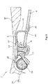
- FIG 3 a small quantity opening position is shown.
- the valve shaft 16 is pivoted by means of an electric motor 30 within a defined angular range, so that the small-volume valve 4, which is firmly connected to the valve shaft 16, lifts the valve cone 8 out of the seat 10 and the small-volume opening 12 is released.
- the small-quantity opening 12 can be opened to a greater or lesser extent, so that a fine adjustment of the exhaust gas recirculation quantity is possible.
- Figure 3 shows a maximum possible angle of rotation of the flap shaft 16 for a small volume control.
- the small-quantity opening position shown also corresponds to a fail-safe position, which is assumed when the electric motor 30 of the valve shaft is not energized due to the spring force of the leaf spring 14.
- the gearbox of the drive motor of the damper shaft is not self-locking. This makes it possible to operate the internal combustion engine in emergency mode in the event of a fault. It is also possible for condensation water that has collected on the register flap 1 to flow off, which otherwise can lead to the register flap freezing in winter.
- FIG. 12 also shows a second fluid opening 32 and a third fluid opening 34, which are formed by the valve housing 20. These fluid openings 32, 34 are also in the Figures 2 and 3 present, but have been omitted for the sake of clarity.
- the small quantity flap 4 ′ In a completely open position of the small quantity flap 4 ′, the small quantity flap 4 ′ is at a distance 36 from an opening edge 38. In this position, the small quantity flap 4 ′ almost completely covers the second fluid opening 32, so that a fluid passing through the second fluid opening 32 is throttled.
- the distance 36 is less than 15 mm.
Description
Die Erfindung betrifft eine Drei-Wege-Abgasrückführungs-Ventilanordnung mit drei Fluidöffnungen für eine Abgasrückführung einer Verbrennungskraftmaschine.The invention relates to a three-way exhaust gas recirculation valve arrangement with three fluid openings for exhaust gas recirculation of an internal combustion engine.
Derartige Ventilanordnungen zur Abgasrückführung sind bekannt und dienen zur Regelung einer In die Verbrennungsräume eines Verbrennungsmotors aus dem Abgastrakt zurückgeführten Abgasmenge zur Reduzierung der Schadstoffemissionen. Die Drei-Wege-Ventilanordnung weist drei Fluidöffnungen bzw. -anschlüsse auf, so dass eine differenzierte Regelung mit einer einzigen Ventilanordnung möglich ist. Eine solche Ventilanordnung wird üblicherweise auf der Niederdruckseite des Abgasstranges, d.h. nach dem Abgasturbolader eingesetzt. Innerhalb dieser Niederdruckseite kann die Ventilanordnung sowohl auf einer heißen als auch auf einer kalten Seite eingesetzt werden. Die heiße Seite liegt in Strömungsrichtung des Abgases vor einem Abgaskühler, die kalte Seite dahinter.Such valve arrangements for exhaust gas recirculation are known and are used to regulate an amount of exhaust gas recirculated from the exhaust gas tract into the combustion chambers of an internal combustion engine in order to reduce pollutant emissions. The three-way valve arrangement has three fluid openings or connections, so that differentiated regulation is possible with a single valve arrangement. Such a valve arrangement is usually used on the low-pressure side of the exhaust line, i.e. after the exhaust gas turbocharger. Within this low-pressure side, the valve arrangement can be used both on a hot and on a cold side. The hot side lies in front of an exhaust gas cooler in the flow direction of the exhaust gas, the cold side behind it.
Aus dem Stand der Technik sind Ventilanordnungen bekannt, bei welchen durch Öffnen einer Klappe Abgas dem Motor zurückgeführt wird. Eine derartige Ventilanordnung ist beispielsweise bekannt aus
Durch Einstellung des Öffnungswinkels und in Abhängigkeit von der anliegenden Druckdifferenz ist die Abgasmenge, welche dem Verbrennungsmotor zurückgeführt wird, einstellbar. Im Motor-Volllastbereich, in welchem lediglich geringe Mengen an Abgas dem Motor zurückgeführt werden sollen, liegen jedoch hohe Druckdifferenzen an der Klappe an, wodurch bereits kleine Öffnungswinkeländerungen zu hohen Abgasmengenänderungen führen. Dadurch ist eine feine Einstellung der rückgeführten Abgasmenge insbesondere erschwert.The amount of exhaust gas that is returned to the internal combustion engine can be adjusted by setting the opening angle and depending on the pressure difference. In the engine full load range, in which only small amounts of exhaust gas are to be returned to the engine, however, there are high pressure differentials at the flap, which means that even small changes in the opening angle become too high Lead to changes in the amount of exhaust gas. As a result, fine adjustment of the amount of recirculated exhaust gas is particularly difficult.
Aus
Die Aufgabe der vorliegenden Erfindung liegt somit darin eine verbesserte Drei-Wege-Abgasrückführungs-Ventilanordnung zu schaffen, welche eine feine Einstellung der Abgasmenge insbesondere im Volllastbereich ermöglicht.The object of the present invention is therefore to create an improved three-way exhaust gas recirculation valve arrangement which enables the amount of exhaust gas to be fine-tuned, particularly in the full-load range.
Die der Erfindung zugrunde liegende Aufgabe wird gelöst durch eine Drei-Wege-Ventilanordnung nach dem unabhängigen Anspruch 1.The object on which the invention is based is achieved by a three-way valve arrangement according to
Als Drei-Wege-Ventil im Sinne der vorliegenden Erfindung wird dabei eine Ventilanordnung mit drei Anschlüssen verstanden, welche durch Öffnen der Klappe eine zusätzliche Einlass-Auslass-Verbindung herstellt. Anspruch 1 spezifiziert eine Registerklappe, die eine Kleinmengenklappe, eine Großmengenklappe und einen Mitnehmer aufweist. Die Kleinmengenklappe weist dabei einen Schließkörper auf, mit welchem eine in der Großmengenklappe vorgesehene Kleinmengenöffnung verschließbar ist. Als Registerklappe nach der vorliegenden Erfindung wird eine Klappe verstanden, welche durch Öffnen verschiedener Klappenelemente unterschiedlich große Öffnungen freigeben kann. Die Kleinmengenklappe liegt bei geschlossener Großmengenklappe innerhalb der Großmengenöffnung, so dass die Kleinmengenöffnung eine kleinere Öffnungsfläche als die Großmengenöffnung hat. Die Kleinmengenklappe verschließt die Kleinmengenöffnung und die Großmengenklappe verschließt die Großmengenöffnung. In einem vollständig geschlossenen Zustand ist somit einer der drei Anschlüsse der Ventilanordnung fluidisch von den beiden anderen Anschlüssen getrennt. Der Mitnehmer ist derart ausgebildet, dass der Öffnungsgrad der Großmengenklappe im Verhältnis zur Kleinmengenklappe begrenzt ist. Ab einem definierten Öffnungsgrad der Kleinmengenklappe wird durch den Mitnehmer die Großmengenklappe bei einer weiteren Öffnungsbewegung der Klappenwelle mit verschwenkt. Dadurch wird es möglich, den maximalen Öffnungswinkel der Kleinmengenklappe zur Großmengenklappe zu begrenzen.A three-way valve in the context of the present invention is understood to mean a valve arrangement with three connections which, by opening the flap, produces an additional inlet-outlet connection.
Da die Kleinmengenklappe eine kleinere Öffnung verschließt als die Großmengenklappe, führen kleine Öffnungswinkeländerungen der Kleinmengenklappe auch zu kleineren Abgasmengenänderungen, verglichen mit gleichen Öffnungswinkeländerungen der Großmengenklappe. Die Abgasmenge kann somit in einem Bereich, in welchem lediglich geringe zurückgeführte Abgasmengen benötigt werden, erheblich feiner eingestellt werden. Somit ist es möglich, auch unter Volllast die zurückgeführte Abgasmenge feiner zu dosieren.Since the small-volume flap closes a smaller opening than the large-volume flap, small changes in the opening angle of the small-volume flap also lead to smaller changes in the amount of exhaust gas compared to the same changes in the opening angle of the large-volume flap. The amount of exhaust gas can thus be set considerably more finely in a range in which only small amounts of recirculated exhaust gas are required. This makes it possible to meter the amount of exhaust gas recirculated more finely, even under full load.
In einer bevorzugten Ausgestaltung der Erfindung ist bei vollständig geöffneter Stellung der Kleinmengenklappe die zweite Öffnung mindestens drosselnd durch die Kleinmengenklappe versperrt. Als vollständig geöffnet im Sinne der Erfindung wird eine Stellung verstanden, bei der die Großmengenöffnung freigegeben ist und der Verschwenkwinkel der Klappenwelle den maximal definierten Wert aufweist. Drosselnd im Sinne der Erfindung wird der Effekt bezeichnet, bei der das Fluid durch die Kleinmengenklappe an der zweiten Öffnung aufgestaut wird. Ein Teil des Fluides kann somit weiterhin die zweite Öffnung passieren. Durch die Drosselung des Fluides an der zweiten Öffnung wird eine wirksamere Rückführung des Abgases zum Verbrennungsmotor gewährleistet.In a preferred embodiment of the invention, when the small quantity flap is in the fully open position, the second opening is blocked at least in a throttling manner by the small quantity flap. In the context of the invention, fully open is understood to mean a position in which the large-volume opening is released and the pivoting angle of the flap shaft has the maximum defined value. Throttling in the sense of the invention is the effect in which the fluid is dammed up by the small volume flap at the second opening. Part of the fluid can therefore continue to pass through the second opening. The throttling of the fluid at the second opening ensures a more effective return of the exhaust gas to the internal combustion engine.
Vorzugsweise ist bei der vollständig geöffneten Stellung der Kleinmengenklappe ein Abstand zwischen der Kleinmengenklappe und einem Rand der zweiten Öffnung höchstens 15 mm und besonders bevorzugt höchstens 10 mm. Der Abstand ist dabei gemessen an einer Stelle des Öffnungsrandes der zweiten Öffnung, bei welcher der sich senkrecht zu einer Öffnungsebene der zweiten Öffnung ergebende Abstand zu der Kleinmengenklappe maximal ist.In the completely open position of the small quantity flap, a distance between the small quantity flap and an edge of the second opening is preferably at most 15 mm and particularly preferably at most 10 mm. The distance is measured at a point on the opening edge of the second opening at which the distance from the small-volume flap, which is perpendicular to an opening plane of the second opening, is at a maximum.
Gemäß einer bevorzugten Ausgestaltung der vorliegenden Erfindung ist der Mitnehmer an der Großmengenklappe vorgesehen. Vorzugsweise ist der Mitnehmer dabei einteilig mit der Großmengenklappe ausgebildet. Es sind jedoch auch Ausgestaltungen des Mitnehmers möglich, bei welcher dieser als separates Teil mittels beispielsweise einer Schraub- oder Nietverbindung mit der Großmengenklappe verbunden wird. In einer bevorzugten Ausgestaltung ist der Mitnehmer in einer Z-Form ausgebildet, wobei ein Ende des Z-förmigen Mitnehmers mit der Großmengenklappe verbunden ist und das andere Ende durch eine Öffnung in der Kleinmengenklappe hindurch tritt und die Kleinmengenklappe hintergreift.According to a preferred embodiment of the present invention, the driver is provided on the large volume flap. The driver is preferably designed in one piece with the large-volume flap. However, configurations of the driver are also possible in which it is connected to the large-volume flap as a separate part by means of, for example, a screw or rivet connection. In a preferred embodiment, the driver is designed in a Z-shape, one end of the Z-shaped driver being connected to the large quantity flap and the other end passing through an opening in the small quantity flap and engaging behind the small quantity flap.
Gemäß einer weiteren bevorzugten Ausgestaltung der vorliegenden Erfindung ist der Mitnehmer alternativ an der Kleinmengenklappe vorgesehen. Auch bei dieser Ausgestaltung, kann der Mitnehmer sowohl einteilig mit der Kleinmengenklappe ausgebildet sein, als auch separat vorliegen.According to a further preferred embodiment of the present invention, the driver is alternatively provided on the small quantity flap. In this embodiment, too, the driver can be designed in one piece with the small quantity flap or can be present separately.
In einem bevorzugten Ausführungsbeispiel ist die Großmengenklappe einseitig an der Klappenwelle angeschlagen. Einseitig angeschlagen bedeutet hierbei, dass die Großmengenklappe um eine randseitige Drehachse, welche einem Rand der Großmengenklappe zugeordnet ist, verschwenkbar ist. Dies hat den Vorteil, dass die Drehachse außerhalb des Fluidstromes positioniert werden kann, so dass der Fluidstrom durch die Drehachse nicht gedrosselt wird.In a preferred embodiment, the large volume flap is hinged on one side of the flap shaft. Hinged on one side means here that the large-volume flap can be pivoted about an edge-side axis of rotation which is assigned to an edge of the large-volume flap. This has the advantage that the axis of rotation is outside of the fluid flow can be positioned so that the fluid flow is not throttled by the axis of rotation.
In einem weiteren bevorzugten Ausführungsbeispiel bildet die Kleinmengenöffnung einen Ventilsitz für den Schließkörper. Dieser Ventilsitz ist dabei an die Form des Schließkörpers angepasst, um einen passgenauen Sitz des Schließkörpers in der Schließstellung zu gewährleisten und somit die Dichtigkeit weiter zu verbessern.In a further preferred embodiment, the small quantity opening forms a valve seat for the closing body. This valve seat is adapted to the shape of the closing body in order to ensure a precise fit of the closing body in the closed position and thus further improve the tightness.
Vorzugsweise ist der Ventilsitzsitz integral mit der Großmengenklappe ausgebildet. Dadurch wird eine Anzahl an Teilen der Ventilanordnung reduziert. Zusätzlich ist eine Befestigung des Ventilsitzes mit der Großmengenklappe nicht notwendig, wodurch ein Herstellungsschritt eingespart wird und dadurch die Ventilanordnung wirtschaftlicher herstellbar ist.The valve seat seat is preferably formed integrally with the large volume flap. This reduces a number of parts of the valve assembly. In addition, it is not necessary to fasten the valve seat to the large-volume flap, which saves a manufacturing step and, as a result, the valve arrangement can be manufactured more economically.
In einer alternativen Ausführungsform wird der Ventilsitz von einem separaten Teil gebildet, welches mit der Großmengenklappe verbunden ist. Dadurch kann die Großmengenklappe aus einem anderen Werkstoff hergestellt werden, als der Ventilsitz, so dass durch Auswahl eines verschleißarmen Werkstoffes der Verschleiß des Ventilsitzes gering gehalten werden kann. Dadurch kann die Lebensdauer der Großmengenklappe verlängert werden. Demgegenüber kann der Großmengenklappenkörper aus einem preiswerten Material hergestellt werden. Damit ist eine wirtschaftliche Herstellung der Großmengenklappe möglich.In an alternative embodiment, the valve seat is formed by a separate part which is connected to the high-volume flap. As a result, the high-volume flap can be made from a different material than the valve seat, so that the wear on the valve seat can be kept low by selecting a low-wear material. This can extend the service life of the large volume flap. In contrast, the large volume valve body can be made of an inexpensive material. This makes it possible to manufacture the large-volume valve economically.
In einer weiteren bevorzugten Ausgestaltung der Erfindung ist der Schließkörper als Ventilkegel ausgebildet, welcher mit einem entsprechend geformten Ventilsitz zusammenwirkt. Ein Ventilkegel hat dabei den Vorteil, dass eine hohe Dichtigkeit der Kleinmengenöffnung gewährleistet ist.In a further preferred embodiment of the invention, the closing body is designed as a valve cone which interacts with a correspondingly shaped valve seat. A valve cone has the advantage that the small-volume opening is guaranteed to be tightly sealed.
Gemäß einer weiteren bevorzugten Ausgestaltung der vorliegenden Erfindung ist das Verbindungselement, das die Großmengenklappe mit der Kleinmengenklappe verbindet in Form einer Feder ausgebildet. Die Feder verspannt dabei die Kleinmengenklappe zu der Großmengenklappe, so dass der Schließkörper von der Kleinmengenöffnung abgehoben wird und beide Klappen bis zu dem durch den Mitnehmer vorgegebenen maximalen Öffnungswinkel zwischen Kleinmengenklappe und Großmengenklappe auseinander gedrückt werden.According to a further preferred embodiment of the present invention, the connecting element which connects the large volume flap to the small volume flap is designed in the form of a spring. The spring braces the small-volume flap to the large-volume flap, so that the closing body is lifted from the small-volume opening and both flaps are pressed apart up to the maximum opening angle between the small-volume flap and large-volume flap specified by the driver.
In einer bevorzugten Ausführungsform wird die Feder durch eine Blattfeder gebildet. Eine Blattfeder hat den Vorteil, dass sie preiswert herstellbar ist. Diese Blattfeder wird vorzugsweise aus einem metallischen Werkstoff wie z.B. Inconel gefertigt. Statt einer Blattfeder ist alternativ ebenso eine Spiralfeder denkbar.In a preferred embodiment, the spring is formed by a leaf spring. A leaf spring has the advantage that it can be manufactured inexpensively. This leaf spring is preferably made of a metallic material such as Inconel. Instead of a leaf spring, a spiral spring is alternatively also conceivable.
Vorzugsweise ist die Klappenwelle über einen Elektromotor angetrieben. Es sind jedoch jegliche dem Fachmann bekannte Antriebsmöglichkeiten denkbar.The flap shaft is preferably driven by an electric motor. However, any drive options known to the person skilled in the art are conceivable.
Weitere Einzelheiten und Vorteile der vorliegenden Erfindung ergeben sich aus der nachfolgenden Beschreibung des Ausführungsbeispiels in Verbindung mit den Zeichnungen. In diesen zeigen:
-
Figur 1 : Eine Explosionszeichnung eines Ausführungsbeispiels der Registerklappe, -
Figur 2 : Ventilanordnung, bei welcher die Registerklappe in einer Schließstellung steht, -
Figur 3 : Ventilanordnung, bei welcher die Registerklappe in einer Kleinmengenöffnungsstellung steht, und -
Figur 4 : Ventilanordnung, bei welcher die Registerklappe in einer Großmengenöffnungsstellung steht.
-
Figure 1 : An exploded view of an embodiment of the register flap, -
Figure 2 : Valve arrangement in which the register flap is in a closed position, -
Figure 3 : Valve arrangement in which the register flap is in a small-volume opening position, and -
Figure 4 : Valve arrangement in which the register flap is in a large-volume opening position.
In
Die in
In the
In
- 11
- RegisterklappeRegister flap
- 22
- Drei-Wege-Abgasrückführungs-VentilanordnungThree-way exhaust gas recirculation valve assembly
- 44th
- KleinmengenklappeSmall volume flap
- 4'4 '
- vollständig geöffnete Kleinmengenklappefully open small volume flap
- 66th
- GroßmengenklappeLarge volume flap
- 88th
- VentilkegelValve cone
- 1010
- VentilsitzValve seat
- 1212th
- KleinmengenöffnungSmall quantity opening
- 1414th
- BlattfederLeaf spring
- 1616
- KlappenwelleFlap shaft
- 1818th
- GroßmengenöffnungBulk opening
- 2020th
- VentilgehäuseValve body
- 2222nd
- MitnehmerCarrier
- 2424
- MitnehmeröffnungDriver opening
- 2626th
- Schenkelleg
- 2828
- Spaltgap
- 3030th
- ElektromotorElectric motor
- 3232
- zweite Fluidöffnungsecond fluid port
- 3434
- dritte Fluidöffnungthird fluid port
- 3636
- Abstanddistance
- 3838
- ÖffnungsrandOpening edge
Claims (14)
- Three-way exhaust gas recirculation valve arrangement (2) comprising three fluid openings (18, 32, 34) for the exhaust gas recirculation of an internal combustion engine, the valve arrangement comprising:- a valve housing (20) forming the first fluid opening (18), the second fluid opening (32) and the third fluid opening (34),- a large-volume opening (18) forming the first fluid opening (18),- a register flap (I) comprising:- a small-volume flap (4) comprising a closing body (8),- a large-volume flap (6) for closing the large-volume opening (18), the large-volume flap (6) comprising a small-volume opening (12) adapted to be closed by the closing body (8), and the small-volume flap (4) being movably connected with the large-volume flap (6) by means of a connecting element, and- a tappet (22) limiting the degree of opening of the large-volume flap (6) to the small-volume flap (4), and- a flap shaft (16) carrying the flaps (4, 6), the flap shaft (16) being continuously movable between:- a closed position in which the large-volume flap (6) closes the large-volume opening (18) and the closing body (8) closes the small-volume opening (12),- a small-volume opening position in which the closing body (8) is spaced from the small-volume flap (12) when the large-volume opening (18) abuts on the small-volume opening (12), and- a large-volume opening position in which the large-volume flap (6) is lifted from the large-volume opening (18) by means of the tappet (22).
- Three-way exhaust gas recirculation valve arrangement (2) of claim 1, wherein in a fully open position of the small-volume flap (4'), the second opening (32) is blocked at least in a throttling manner by the small-volume flap (4').
- Three-way exhaust gas recirculation valve arrangement (2) of claim 2, wherein in a fully open position of the small-volume flap (4'), the small-volume flap (4') is spaced not more than 15 mm and preferably not more than 10 mm from the second opening (32).
- Three-way exhaust gas recirculation valve arrangement (2) of one of the preceding claims, wherein the tappet (22) is provided on the high-volume flap (6).
- Three-way exhaust gas recirculation valve arrangement (2) of claims 1 to 3, in which the tappet (22) is provided on the small-volume flap (4).
- Three-way exhaust gas recirculation valve arrangement (2) of one of the preceding claims, wherein the large-volume flap (6) is hinged to one side of the large-volume opening (18).
- Three-way exhaust gas recirculation valve arrangement (2) of one of the preceding claims, wherein the small-volume opening (12) forms a valve seat (10) for the closing body (8).
- Three-way exhaust gas recirculation valve arrangement (2) of claim 7, wherein the valve seat (10) is provided as an integral part of the high-volume flap (6).
- Three-way exhaust gas recirculation valve arrangement (2) of claim 7, wherein the valve seat (10) is provided as a separate part of the high-volume flap (6).
- Three-way exhaust gas recirculation valve arrangement (2) of claims 7 to 9, wherein the closing body is a valve plug (8).
- Three-way exhaust gas recirculation valve arrangement (2) of one of the preceding claims, wherein the connecting element is a spring.
- Three-way exhaust gas recirculation valve arrangement (2) of claim 11, wherein the spring is a leaf spring (14).
- Three-way exhaust gas recirculation valve assembly (2) of claim 11, wherein the spring is a coil spring.
- Three-way exhaust gas recirculation valve arrangement (2) of one of the preceding claims, wherein the flap shaft (16) is driven via an electric motor (30).
Applications Claiming Priority (2)
| Application Number | Priority Date | Filing Date | Title |
|---|---|---|---|
| DE102015110984.0A DE102015110984B4 (en) | 2015-07-07 | 2015-07-07 | Three-way exhaust gas recirculation valve assembly with three fluid ports for exhaust gas recirculation |
| PCT/EP2016/062373 WO2017005416A1 (en) | 2015-07-07 | 2016-06-01 | Three-way exhaust-gas recirculation valve assembly having three fluid openings for exhaust-gas recirculation |
Publications (2)
| Publication Number | Publication Date |
|---|---|
| EP3320202A1 EP3320202A1 (en) | 2018-05-16 |
| EP3320202B1 true EP3320202B1 (en) | 2021-08-04 |
Family
ID=56096633
Family Applications (1)
| Application Number | Title | Priority Date | Filing Date |
|---|---|---|---|
| EP16726315.1A Active EP3320202B1 (en) | 2015-07-07 | 2016-06-01 | Three way exhaust gas recirculation valve |
Country Status (3)
| Country | Link |
|---|---|
| EP (1) | EP3320202B1 (en) |
| DE (1) | DE102015110984B4 (en) |
| WO (1) | WO2017005416A1 (en) |
Families Citing this family (3)
| Publication number | Priority date | Publication date | Assignee | Title |
|---|---|---|---|---|
| DE102018205385B4 (en) | 2018-04-10 | 2020-06-10 | Ford Global Technologies, Llc | Valve flap arrangement for a three-way exhaust gas recirculation valve |
| DE102018210078B4 (en) * | 2018-06-21 | 2022-01-05 | Ford Global Technologies, Llc | Valve unit and use of such a valve unit |
| DE102019219399A1 (en) | 2019-01-17 | 2020-07-23 | Ford Global Technologies, Llc | Valve flap to control fluid flow through a flow channel and valve |
Family Cites Families (6)
| Publication number | Priority date | Publication date | Assignee | Title |
|---|---|---|---|---|
| EP1254309B1 (en) * | 2000-02-10 | 2005-07-20 | Siemens Aktiengesellschaft | Throttle valve arrangement with emergency air device |
| DE10216537B3 (en) * | 2002-04-15 | 2004-02-05 | Visteon Global Technologies, Inc., Dearborn | Reversing device for flowing media, in particular switch valve for the exhaust gases of an internal combustion engine |
| FR2917801A1 (en) * | 2007-06-21 | 2008-12-26 | Faurecia Sys Echappement | Three-way control valve for exhaust line of motor vehicle, has closing unit with compressor valve coupled to jumper unit, where jumper unit is used for adopting closing position in which one of three openings is closed by compressor valve |
| JP5359324B2 (en) * | 2009-01-30 | 2013-12-04 | 大豊工業株式会社 | Exhaust throttle valve for internal combustion engine |
| EP2592258B2 (en) | 2011-11-08 | 2017-12-06 | Cooper-Standard Automotive (Deutschland) GmbH | Exhaust gas recirculation valve |
| DE102013108426A1 (en) * | 2013-08-05 | 2015-02-05 | Faurecia Emissions Control Technologies, Germany Gmbh | Valve assembly and exhaust system |
-
2015
- 2015-07-07 DE DE102015110984.0A patent/DE102015110984B4/en not_active Expired - Fee Related
-
2016
- 2016-06-01 WO PCT/EP2016/062373 patent/WO2017005416A1/en active Application Filing
- 2016-06-01 EP EP16726315.1A patent/EP3320202B1/en active Active
Also Published As
| Publication number | Publication date |
|---|---|
| EP3320202A1 (en) | 2018-05-16 |
| WO2017005416A1 (en) | 2017-01-12 |
| DE102015110984A1 (en) | 2017-01-12 |
| DE102015110984B4 (en) | 2019-05-29 |
Similar Documents
| Publication | Publication Date | Title |
|---|---|---|
| EP1762712B1 (en) | Bypass valve for Internal combustion engines | |
| EP3012445B1 (en) | Control device for a combustion engine | |
| WO2009106161A1 (en) | Turbocharger comprising an actuator for opening and closing a wastegate duct | |
| WO2011101005A1 (en) | Turbine for an exhaust gas turbocharger | |
| WO2015124790A1 (en) | Exhaust gas deflector | |
| EP3320202B1 (en) | Three way exhaust gas recirculation valve | |
| DE102008050252B4 (en) | Valve device for internal combustion engines, in particular secondary air valve | |
| WO2014075774A1 (en) | Exhaust gas pipe section of a turbine | |
| EP2820284B1 (en) | Mixing valve of an internal combustion engine | |
| DE102004040649B4 (en) | Valve arrangement for an expansion valve, in particular for refrigeration systems in vehicle air conditioning systems | |
| EP3615787A1 (en) | Control device for an internal combustion engine | |
| EP2653710B1 (en) | Valve device for a combustion engine | |
| DE102005041146A1 (en) | Rotary valve piston for regulating the temperature and quantity of recycled exhaust gases in combustion engines comprises a valve housing and a regulating element having a conical casing surface | |
| DE102009015184B4 (en) | flap valve | |
| DE102012110872A1 (en) | Control device for an exhaust gas guide section of a turbine and exhaust gas guide section for a turbine | |
| DE102011050263A1 (en) | Valve device for an internal combustion engine | |
| DE10249448B4 (en) | Bypass valve device | |
| DE102016214784A1 (en) | Valve device of an internal combustion engine | |
| EP4090841A1 (en) | Valve device for an internal combustion engine | |
| DE112012006385T5 (en) | Relief valve for a turbocharged engine | |
| EP3551867B1 (en) | Flap device | |
| DE102019116156A1 (en) | Valve, exhaust system for an internal combustion engine and vehicle with an internal combustion engine | |
| CH697363B1 (en) | Distributor. | |
| DE10212136C1 (en) | flush valve | |
| EP3538753B1 (en) | Control device for an internal combustion engine |
Legal Events
| Date | Code | Title | Description |
|---|---|---|---|
| STAA | Information on the status of an ep patent application or granted ep patent |
Free format text: STATUS: THE INTERNATIONAL PUBLICATION HAS BEEN MADE |
|
| PUAI | Public reference made under article 153(3) epc to a published international application that has entered the european phase |
Free format text: ORIGINAL CODE: 0009012 |
|
| STAA | Information on the status of an ep patent application or granted ep patent |
Free format text: STATUS: REQUEST FOR EXAMINATION WAS MADE |
|
| 17P | Request for examination filed |
Effective date: 20171213 |
|
| AK | Designated contracting states |
Kind code of ref document: A1 Designated state(s): AL AT BE BG CH CY CZ DE DK EE ES FI FR GB GR HR HU IE IS IT LI LT LU LV MC MK MT NL NO PL PT RO RS SE SI SK SM TR |
|
| AX | Request for extension of the european patent |
Extension state: BA ME |
|
| DAV | Request for validation of the european patent (deleted) | ||
| DAX | Request for extension of the european patent (deleted) | ||
| GRAP | Despatch of communication of intention to grant a patent |
Free format text: ORIGINAL CODE: EPIDOSNIGR1 |
|
| STAA | Information on the status of an ep patent application or granted ep patent |
Free format text: STATUS: GRANT OF PATENT IS INTENDED |
|
| INTG | Intention to grant announced |
Effective date: 20210223 |
|
| RIN1 | Information on inventor provided before grant (corrected) |
Inventor name: VIERKOTTEN, DIRK Inventor name: SUTTY, PATRICK Inventor name: PAFFRATH, HOLGER Inventor name: REIMERS, THORSTEN Inventor name: FASSBENDER, ULRICH |
|
| GRAS | Grant fee paid |
Free format text: ORIGINAL CODE: EPIDOSNIGR3 |
|
| GRAA | (expected) grant |
Free format text: ORIGINAL CODE: 0009210 |
|
| STAA | Information on the status of an ep patent application or granted ep patent |
Free format text: STATUS: THE PATENT HAS BEEN GRANTED |
|
| AK | Designated contracting states |
Kind code of ref document: B1 Designated state(s): AL AT BE BG CH CY CZ DE DK EE ES FI FR GB GR HR HU IE IS IT LI LT LU LV MC MK MT NL NO PL PT RO RS SE SI SK SM TR |
|
| REG | Reference to a national code |
Ref country code: GB Ref legal event code: FG4D Free format text: NOT ENGLISH |
|
| REG | Reference to a national code |
Ref country code: AT Ref legal event code: REF Ref document number: 1417217 Country of ref document: AT Kind code of ref document: T Effective date: 20210815 |
|
| REG | Reference to a national code |
Ref country code: CH Ref legal event code: EP |
|
| REG | Reference to a national code |
Ref country code: DE Ref legal event code: R096 Ref document number: 502016013542 Country of ref document: DE |
|
| REG | Reference to a national code |
Ref country code: IE Ref legal event code: FG4D Free format text: LANGUAGE OF EP DOCUMENT: GERMAN |
|
| REG | Reference to a national code |
Ref country code: LT Ref legal event code: MG9D |
|
| REG | Reference to a national code |
Ref country code: NL Ref legal event code: MP Effective date: 20210804 |
|
| PG25 | Lapsed in a contracting state [announced via postgrant information from national office to epo] |
Ref country code: LT Free format text: LAPSE BECAUSE OF FAILURE TO SUBMIT A TRANSLATION OF THE DESCRIPTION OR TO PAY THE FEE WITHIN THE PRESCRIBED TIME-LIMIT Effective date: 20210804 Ref country code: BG Free format text: LAPSE BECAUSE OF FAILURE TO SUBMIT A TRANSLATION OF THE DESCRIPTION OR TO PAY THE FEE WITHIN THE PRESCRIBED TIME-LIMIT Effective date: 20211104 Ref country code: HR Free format text: LAPSE BECAUSE OF FAILURE TO SUBMIT A TRANSLATION OF THE DESCRIPTION OR TO PAY THE FEE WITHIN THE PRESCRIBED TIME-LIMIT Effective date: 20210804 Ref country code: FI Free format text: LAPSE BECAUSE OF FAILURE TO SUBMIT A TRANSLATION OF THE DESCRIPTION OR TO PAY THE FEE WITHIN THE PRESCRIBED TIME-LIMIT Effective date: 20210804 Ref country code: ES Free format text: LAPSE BECAUSE OF FAILURE TO SUBMIT A TRANSLATION OF THE DESCRIPTION OR TO PAY THE FEE WITHIN THE PRESCRIBED TIME-LIMIT Effective date: 20210804 Ref country code: PT Free format text: LAPSE BECAUSE OF FAILURE TO SUBMIT A TRANSLATION OF THE DESCRIPTION OR TO PAY THE FEE WITHIN THE PRESCRIBED TIME-LIMIT Effective date: 20211206 Ref country code: NO Free format text: LAPSE BECAUSE OF FAILURE TO SUBMIT A TRANSLATION OF THE DESCRIPTION OR TO PAY THE FEE WITHIN THE PRESCRIBED TIME-LIMIT Effective date: 20211104 Ref country code: RS Free format text: LAPSE BECAUSE OF FAILURE TO SUBMIT A TRANSLATION OF THE DESCRIPTION OR TO PAY THE FEE WITHIN THE PRESCRIBED TIME-LIMIT Effective date: 20210804 Ref country code: SE Free format text: LAPSE BECAUSE OF FAILURE TO SUBMIT A TRANSLATION OF THE DESCRIPTION OR TO PAY THE FEE WITHIN THE PRESCRIBED TIME-LIMIT Effective date: 20210804 |
|
| PG25 | Lapsed in a contracting state [announced via postgrant information from national office to epo] |
Ref country code: PL Free format text: LAPSE BECAUSE OF FAILURE TO SUBMIT A TRANSLATION OF THE DESCRIPTION OR TO PAY THE FEE WITHIN THE PRESCRIBED TIME-LIMIT Effective date: 20210804 Ref country code: LV Free format text: LAPSE BECAUSE OF FAILURE TO SUBMIT A TRANSLATION OF THE DESCRIPTION OR TO PAY THE FEE WITHIN THE PRESCRIBED TIME-LIMIT Effective date: 20210804 Ref country code: GR Free format text: LAPSE BECAUSE OF FAILURE TO SUBMIT A TRANSLATION OF THE DESCRIPTION OR TO PAY THE FEE WITHIN THE PRESCRIBED TIME-LIMIT Effective date: 20211105 |
|
| PG25 | Lapsed in a contracting state [announced via postgrant information from national office to epo] |
Ref country code: NL Free format text: LAPSE BECAUSE OF FAILURE TO SUBMIT A TRANSLATION OF THE DESCRIPTION OR TO PAY THE FEE WITHIN THE PRESCRIBED TIME-LIMIT Effective date: 20210804 |
|
| PG25 | Lapsed in a contracting state [announced via postgrant information from national office to epo] |
Ref country code: DK Free format text: LAPSE BECAUSE OF FAILURE TO SUBMIT A TRANSLATION OF THE DESCRIPTION OR TO PAY THE FEE WITHIN THE PRESCRIBED TIME-LIMIT Effective date: 20210804 |
|
| REG | Reference to a national code |
Ref country code: DE Ref legal event code: R097 Ref document number: 502016013542 Country of ref document: DE |
|
| PG25 | Lapsed in a contracting state [announced via postgrant information from national office to epo] |
Ref country code: SM Free format text: LAPSE BECAUSE OF FAILURE TO SUBMIT A TRANSLATION OF THE DESCRIPTION OR TO PAY THE FEE WITHIN THE PRESCRIBED TIME-LIMIT Effective date: 20210804 Ref country code: SK Free format text: LAPSE BECAUSE OF FAILURE TO SUBMIT A TRANSLATION OF THE DESCRIPTION OR TO PAY THE FEE WITHIN THE PRESCRIBED TIME-LIMIT Effective date: 20210804 Ref country code: RO Free format text: LAPSE BECAUSE OF FAILURE TO SUBMIT A TRANSLATION OF THE DESCRIPTION OR TO PAY THE FEE WITHIN THE PRESCRIBED TIME-LIMIT Effective date: 20210804 Ref country code: EE Free format text: LAPSE BECAUSE OF FAILURE TO SUBMIT A TRANSLATION OF THE DESCRIPTION OR TO PAY THE FEE WITHIN THE PRESCRIBED TIME-LIMIT Effective date: 20210804 Ref country code: CZ Free format text: LAPSE BECAUSE OF FAILURE TO SUBMIT A TRANSLATION OF THE DESCRIPTION OR TO PAY THE FEE WITHIN THE PRESCRIBED TIME-LIMIT Effective date: 20210804 Ref country code: AL Free format text: LAPSE BECAUSE OF FAILURE TO SUBMIT A TRANSLATION OF THE DESCRIPTION OR TO PAY THE FEE WITHIN THE PRESCRIBED TIME-LIMIT Effective date: 20210804 |
|
| PLBE | No opposition filed within time limit |
Free format text: ORIGINAL CODE: 0009261 |
|
| STAA | Information on the status of an ep patent application or granted ep patent |
Free format text: STATUS: NO OPPOSITION FILED WITHIN TIME LIMIT |
|
| 26N | No opposition filed |
Effective date: 20220506 |
|
| PG25 | Lapsed in a contracting state [announced via postgrant information from national office to epo] |
Ref country code: IT Free format text: LAPSE BECAUSE OF FAILURE TO SUBMIT A TRANSLATION OF THE DESCRIPTION OR TO PAY THE FEE WITHIN THE PRESCRIBED TIME-LIMIT Effective date: 20210804 |
|
| PG25 | Lapsed in a contracting state [announced via postgrant information from national office to epo] |
Ref country code: SI Free format text: LAPSE BECAUSE OF FAILURE TO SUBMIT A TRANSLATION OF THE DESCRIPTION OR TO PAY THE FEE WITHIN THE PRESCRIBED TIME-LIMIT Effective date: 20210804 |
|
| PG25 | Lapsed in a contracting state [announced via postgrant information from national office to epo] |
Ref country code: MC Free format text: LAPSE BECAUSE OF FAILURE TO SUBMIT A TRANSLATION OF THE DESCRIPTION OR TO PAY THE FEE WITHIN THE PRESCRIBED TIME-LIMIT Effective date: 20210804 |
|
| REG | Reference to a national code |
Ref country code: CH Ref legal event code: PL |
|
| REG | Reference to a national code |
Ref country code: BE Ref legal event code: MM Effective date: 20220630 |
|
| PG25 | Lapsed in a contracting state [announced via postgrant information from national office to epo] |
Ref country code: LU Free format text: LAPSE BECAUSE OF NON-PAYMENT OF DUE FEES Effective date: 20220601 Ref country code: LI Free format text: LAPSE BECAUSE OF NON-PAYMENT OF DUE FEES Effective date: 20220630 Ref country code: IE Free format text: LAPSE BECAUSE OF NON-PAYMENT OF DUE FEES Effective date: 20220601 Ref country code: CH Free format text: LAPSE BECAUSE OF NON-PAYMENT OF DUE FEES Effective date: 20220630 |
|
| PG25 | Lapsed in a contracting state [announced via postgrant information from national office to epo] |
Ref country code: BE Free format text: LAPSE BECAUSE OF NON-PAYMENT OF DUE FEES Effective date: 20220630 |
|
| PGFP | Annual fee paid to national office [announced via postgrant information from national office to epo] |
Ref country code: FR Payment date: 20230622 Year of fee payment: 8 Ref country code: DE Payment date: 20230620 Year of fee payment: 8 |
|
| REG | Reference to a national code |
Ref country code: AT Ref legal event code: MM01 Ref document number: 1417217 Country of ref document: AT Kind code of ref document: T Effective date: 20220601 |
|
| PG25 | Lapsed in a contracting state [announced via postgrant information from national office to epo] |
Ref country code: AT Free format text: LAPSE BECAUSE OF NON-PAYMENT OF DUE FEES Effective date: 20220601 |
|
| PGFP | Annual fee paid to national office [announced via postgrant information from national office to epo] |
Ref country code: GB Payment date: 20230622 Year of fee payment: 8 |
|
| PG25 | Lapsed in a contracting state [announced via postgrant information from national office to epo] |
Ref country code: HU Free format text: LAPSE BECAUSE OF FAILURE TO SUBMIT A TRANSLATION OF THE DESCRIPTION OR TO PAY THE FEE WITHIN THE PRESCRIBED TIME-LIMIT; INVALID AB INITIO Effective date: 20160601 |