EP3319739B1 - Non-planar and non-symmetrical piezolectric crystals and reflectors - Google Patents
Non-planar and non-symmetrical piezolectric crystals and reflectors Download PDFInfo
- Publication number
- EP3319739B1 EP3319739B1 EP16753490.8A EP16753490A EP3319739B1 EP 3319739 B1 EP3319739 B1 EP 3319739B1 EP 16753490 A EP16753490 A EP 16753490A EP 3319739 B1 EP3319739 B1 EP 3319739B1
- Authority
- EP
- European Patent Office
- Prior art keywords
- piezoelectric material
- acoustic
- reflector
- fluid
- standing wave
- Prior art date
- Legal status (The legal status is an assumption and is not a legal conclusion. Google has not performed a legal analysis and makes no representation as to the accuracy of the status listed.)
- Active
Links
- 0 C*(CCC12)C1*2=C Chemical compound C*(CCC12)C1*2=C 0.000 description 1
Images








Classifications
-
- B—PERFORMING OPERATIONS; TRANSPORTING
- B06—GENERATING OR TRANSMITTING MECHANICAL VIBRATIONS IN GENERAL
- B06B—METHODS OR APPARATUS FOR GENERATING OR TRANSMITTING MECHANICAL VIBRATIONS OF INFRASONIC, SONIC, OR ULTRASONIC FREQUENCY, e.g. FOR PERFORMING MECHANICAL WORK IN GENERAL
- B06B1/00—Methods or apparatus for generating mechanical vibrations of infrasonic, sonic, or ultrasonic frequency
- B06B1/02—Methods or apparatus for generating mechanical vibrations of infrasonic, sonic, or ultrasonic frequency making use of electrical energy
- B06B1/06—Methods or apparatus for generating mechanical vibrations of infrasonic, sonic, or ultrasonic frequency making use of electrical energy operating with piezoelectric effect or with electrostriction
- B06B1/0603—Methods or apparatus for generating mechanical vibrations of infrasonic, sonic, or ultrasonic frequency making use of electrical energy operating with piezoelectric effect or with electrostriction using a piezoelectric bender, e.g. bimorph
-
- B—PERFORMING OPERATIONS; TRANSPORTING
- B06—GENERATING OR TRANSMITTING MECHANICAL VIBRATIONS IN GENERAL
- B06B—METHODS OR APPARATUS FOR GENERATING OR TRANSMITTING MECHANICAL VIBRATIONS OF INFRASONIC, SONIC, OR ULTRASONIC FREQUENCY, e.g. FOR PERFORMING MECHANICAL WORK IN GENERAL
- B06B1/00—Methods or apparatus for generating mechanical vibrations of infrasonic, sonic, or ultrasonic frequency
- B06B1/02—Methods or apparatus for generating mechanical vibrations of infrasonic, sonic, or ultrasonic frequency making use of electrical energy
- B06B1/0207—Driving circuits
- B06B1/0223—Driving circuits for generating signals continuous in time
- B06B1/0238—Driving circuits for generating signals continuous in time of a single frequency, e.g. a sine-wave
-
- B—PERFORMING OPERATIONS; TRANSPORTING
- B01—PHYSICAL OR CHEMICAL PROCESSES OR APPARATUS IN GENERAL
- B01D—SEPARATION
- B01D21/00—Separation of suspended solid particles from liquids by sedimentation
- B01D21/0009—Settling tanks making use of electricity or magnetism
-
- B—PERFORMING OPERATIONS; TRANSPORTING
- B01—PHYSICAL OR CHEMICAL PROCESSES OR APPARATUS IN GENERAL
- B01D—SEPARATION
- B01D21/00—Separation of suspended solid particles from liquids by sedimentation
- B01D21/28—Mechanical auxiliary equipment for acceleration of sedimentation, e.g. by vibrators or the like
- B01D21/283—Settling tanks provided with vibrators
-
- B—PERFORMING OPERATIONS; TRANSPORTING
- B06—GENERATING OR TRANSMITTING MECHANICAL VIBRATIONS IN GENERAL
- B06B—METHODS OR APPARATUS FOR GENERATING OR TRANSMITTING MECHANICAL VIBRATIONS OF INFRASONIC, SONIC, OR ULTRASONIC FREQUENCY, e.g. FOR PERFORMING MECHANICAL WORK IN GENERAL
- B06B1/00—Methods or apparatus for generating mechanical vibrations of infrasonic, sonic, or ultrasonic frequency
- B06B1/02—Methods or apparatus for generating mechanical vibrations of infrasonic, sonic, or ultrasonic frequency making use of electrical energy
- B06B1/06—Methods or apparatus for generating mechanical vibrations of infrasonic, sonic, or ultrasonic frequency making use of electrical energy operating with piezoelectric effect or with electrostriction
- B06B1/0644—Methods or apparatus for generating mechanical vibrations of infrasonic, sonic, or ultrasonic frequency making use of electrical energy operating with piezoelectric effect or with electrostriction using a single piezoelectric element
-
- B—PERFORMING OPERATIONS; TRANSPORTING
- B06—GENERATING OR TRANSMITTING MECHANICAL VIBRATIONS IN GENERAL
- B06B—METHODS OR APPARATUS FOR GENERATING OR TRANSMITTING MECHANICAL VIBRATIONS OF INFRASONIC, SONIC, OR ULTRASONIC FREQUENCY, e.g. FOR PERFORMING MECHANICAL WORK IN GENERAL
- B06B3/00—Methods or apparatus specially adapted for transmitting mechanical vibrations of infrasonic, sonic, or ultrasonic frequency
- B06B3/04—Methods or apparatus specially adapted for transmitting mechanical vibrations of infrasonic, sonic, or ultrasonic frequency involving focusing or reflecting
-
- C—CHEMISTRY; METALLURGY
- C12—BIOCHEMISTRY; BEER; SPIRITS; WINE; VINEGAR; MICROBIOLOGY; ENZYMOLOGY; MUTATION OR GENETIC ENGINEERING
- C12M—APPARATUS FOR ENZYMOLOGY OR MICROBIOLOGY; APPARATUS FOR CULTURING MICROORGANISMS FOR PRODUCING BIOMASS, FOR GROWING CELLS OR FOR OBTAINING FERMENTATION OR METABOLIC PRODUCTS, i.e. BIOREACTORS OR FERMENTERS
- C12M47/00—Means for after-treatment of the produced biomass or of the fermentation or metabolic products, e.g. storage of biomass
- C12M47/02—Separating microorganisms from the culture medium; Concentration of biomass
-
- G—PHYSICS
- G10—MUSICAL INSTRUMENTS; ACOUSTICS
- G10K—SOUND-PRODUCING DEVICES; METHODS OR DEVICES FOR PROTECTING AGAINST, OR FOR DAMPING, NOISE OR OTHER ACOUSTIC WAVES IN GENERAL; ACOUSTICS NOT OTHERWISE PROVIDED FOR
- G10K11/00—Methods or devices for transmitting, conducting or directing sound in general; Methods or devices for protecting against, or for damping, noise or other acoustic waves in general
- G10K11/18—Methods or devices for transmitting, conducting or directing sound
- G10K11/20—Reflecting arrangements
- G10K11/205—Reflecting arrangements for underwater use
-
- H—ELECTRICITY
- H03—ELECTRONIC CIRCUITRY
- H03H—IMPEDANCE NETWORKS, e.g. RESONANT CIRCUITS; RESONATORS
- H03H9/00—Networks comprising electromechanical or electro-acoustic elements; Electromechanical resonators
- H03H9/15—Constructional features of resonators consisting of piezoelectric or electrostrictive material
- H03H9/17—Constructional features of resonators consisting of piezoelectric or electrostrictive material having a single resonator
-
- H—ELECTRICITY
- H10—SEMICONDUCTOR DEVICES; ELECTRIC SOLID-STATE DEVICES NOT OTHERWISE PROVIDED FOR
- H10N—ELECTRIC SOLID-STATE DEVICES NOT OTHERWISE PROVIDED FOR
- H10N30/00—Piezoelectric or electrostrictive devices
- H10N30/80—Constructional details
- H10N30/85—Piezoelectric or electrostrictive active materials
Definitions
- the present disclosure relates to the use of ultrasonically generated acoustic standing waves to achieve trapping, concentration, and separation of suspended-phase components and thereby remove such contaminants from a fluid medium such as water.
- the acoustic standing waves may be created by exciting the piezoelectric crystal of an ultrasonic transducer.
- Piezoelectric crystals may be composed of any material that is able to generate a piezoelectric effect, i.e. vibrate when subjected to an external voltage.
- a conventional material that is used to make piezoelectric crystals is lead zirconate titanate (PZT).
- PZT lead zirconate titanate
- Piezoelectric ceramics are traditionally a mass of perovskite ceramic crystals composed of a small, tetravalent metal ion (e.g., titanium, zirconium) in a lattice of larger, divalent metal ions (e.g., lead, barium) and oxygen ions.
- a piezoelectric PZT crystal can be made by mixing fine powders of the component metal oxides in specific proportions. This mixture is then heated to form a uniform powder. An organic binder is mixed with the metal oxides and formed into desired shapes (e.g., plates, rods, discs). The formed materials are heated at high temperatures that sinter the mixture and form a dense crystalline structure. The sintered parts are then cooled and subsequently shaped or trimmed to desired specifications. Electrodes are applied to the appropriate surfaces of the PZT crystal using processes such as electroless nickel plating or a silver/glass bead mixture coating that is heated and fused on the surface of the crystal.
- Exposing the piezoelectric crystal to an electric charge (i.e. voltage) either in air or a liquid fluid generates pressure waves.
- a function generator may be used to apply a specific frequency or group of frequencies to the piezoelectric crystal such that the pressure waves have a specific frequency.
- An amplifier may be used to apply higher voltages to the piezoelectric crystal at the frequencies generated by the function generator.
- the face of the piezoelectric crystal is flat and thus the waves generated from the piezoelectric crystal are uniform across the face of the crystal.
- a flat-faced piezoelectric crystal can be perturbed in a multi-mode fashion so as to generate multi-dimensional acoustic standing waves. These higher order modes of the piezoelectric crystal allow for multiple trapping lines to be formed in the acoustic standing wave, thus forming a multi-dimensional acoustic standing wave.
- the document US 2014/0377834 A1 describes a method of using an acoustic standing wave to separate components from a multi-component fluid, such as animal cells from fluid-cell mixture, in a fluid flow scheme with an acoustophoresis device.
- the flow scheme and device allows for trapping of falling cells as the cells coalesce, agglomerate, and the weight of the agglomerated mass overcomes the drag and ultrasonic standing wave forces in the device. It is generally mentioned that a reflector of the acoustophoresis device may have a non-planar surface.
- the present disclosure relates, in various embodiments, to acoustophoretic devices and methods of separating a second fluid or a particulate from a host fluid.
- a multi-dimensional acoustic standing wave(s) emanating from a non-planar face of a piezoelectric material is used to continuously trap the second fluid or particulate, which then agglomerates, aggregates, clumps, or coalesces together, and subsequently rises or settles out of the host fluid due to buoyancy or gravity forces, and exits the acoustic chamber.
- the non-planar piezoelectric material only needs to be exposed to a single frequency, rather than a group of frequencies, to generate a multi-dimensional acoustic standing wave.
- acoustophoretic devices comprising: an acoustic chamber having at least one inlet and at least one outlet; at least one ultrasonic transducer located on a wall of the acoustic chamber; and a reflector located on a wall on the opposite side of the acoustic chamber from the at least one ultrasonic transducer.
- the at least one ultrasonic transducer includes a piezoelectric material driven by a voltage signal to create a multi-dimensional acoustic standing wave in the acoustic chamber emanating from the piezoelectric material.
- the piezoelectric material and/or the reflector includes a non-planar surface, wherein the non-planar surface is a faceted surface.
- the faceted surface of the piezoelectric material is poled in a direction substantially perpendicular to a second face of the piezoelectric material.
- the faceted surface of the piezoelectric material can be defined by a step function.
- the reflector also has a faceted surface which can be defined by a step function.
- the piezoelectric material may be planar and the reflector includes the faceted surface.
- the at least one ultrasonic transducer can have a non-symmetrical shape, such as a trapezoidal shape.
- the reflector can also have a non-symmetrical shape, such as a trapezoidal shape.
- the methods comprise flowing a mixture of the host fluid and the second fluid or particulate through an acoustophoretic device.
- the acoustophoretic device comprises an acoustic chamber having at least one inlet and at least one outlet; at least one ultrasonic transducer located on a wall of the acoustic chamber; and a reflector located on a wall on the opposite side of the acoustic chamber from the at least one ultrasonic transducer.
- the at least one ultrasonic transducer includes a piezoelectric material driven by a voltage signal to create a multi-dimensional acoustic standing wave in the acoustic chamber emanating from the piezoelectric material.
- the methods further comprise sending a voltage signal to drive the at least one ultrasonic transducer to create the multi-dimensional acoustic standing wave in the acoustic chamber such that the second fluid or particulate is continuously trapped in the standing wave, and then agglomerates, aggregates, clumps, or coalesces together, and continuously rises or settles out of the host fluid due to enhanced buoyancy or gravity forces, and exits the acoustic chamber.
- the piezoelectric material and/or the reflector includes a non-planar surface, wherein the non-planar surface is a faceted surface.
- the voltage signal can be a sinusoidal, triangular, pulsed or similar waveform.
- the voltage signal can have a frequency of from about 100 kHz to about 20 MHz.
- the mixture of the host fluid and the second fluid or particulate is continuously flowed through the acoustic chamber.
- the second fluid or particulate can include at least one cell selected from the group consisting of CHO cells, T-cells, and yeast cells.
- Flow rates through the acoustic chamber can be from about 1 mL per minute to about 50 liters per hour.
- the methods and devices of the present disclosure may be capable of separation efficiencies of 90% and more for cell concentrations from as low as 50,000 cells per milliliter of fluid to 80,000,000 cells per milliliter of fluid.
- Separation of materials may also include particulates separated from a primary fluid. This would include microspheres, microbubbles, microcarriers and the like. These materials may be solid or hollow and have a positive or negative contrast factor.
- the faceted surface of the reflector can include a plurality of facet clusters or a plurality of wells.
- the multi-dimensional standing wave results in an acoustic radiation force having an axial force component and a lateral force component that are the same order of magnitude.
- the acoustic standing wave may be a multi-dimensional acoustic standing wave (e.g., a three-dimensional acoustic standing wave). Examples of such multi-dimensional acoustic standing waves can be found in commonly owned U.S. Patent No. 9,228,183 .
- the acoustic standing wave can be a planar acoustic standing wave.
- the acoustic standing wave may be a combination of a planar acoustic standing wave and a multi-dimensional acoustic standing wave, such as where the planar acoustic standing wave and multidimensional acoustic standing wave are super-positioned on each other.
- the modifier "about” used in connection with a quantity is inclusive of the stated value and has the meaning dictated by the context. When used in the context of a range, the modifier “about” should also be considered as disclosing the range defined by the absolute values of the two endpoints. For example, the range of “from about 2 to about 10” also discloses the range “from 2 to 10.”
- the term “about” may refer to plus or minus 10% of the indicated number. For example, “about 10%” may indicate a range of 9% to 11%, and “about 1" may mean from 0.9-1.1.
- the terms “upper” and “lower” are relative to each other in location, i.e. an upper component is located at a higher elevation than a lower component in a given orientation, but these terms can change if the device is flipped.
- the terms “inlet” and “outlet” are relative to a fluid flowing through them with respect to a given structure, e.g. a fluid flows through the inlet into the structure and flows through the outlet out of the structure.
- upstream and “downstream” are relative to the direction in which a fluid flows through various components, i.e. the flow fluids through an upstream component prior to flowing through the downstream component. It should be noted that in a loop, a first component can be described as being both upstream of and downstream of a second component.
- top and bottom are used to refer to surfaces where the top is always higher than the bottom/base relative to an absolute reference, i.e. the surface of the earth.
- upwards and “downwards” are also relative to an absolute reference; upwards is always against the gravity of the earth.
- Two numbers are of the same order of magnitude if the quotient of the larger number divided by the smaller number is a value of at least 1 and less than 10.
- Acoustophoresis is the separation of particles and secondary fluids from a primary or host fluid using high-intensity acoustic standing waves, and without the use of membranes or physical size exclusion filters. It has been known that high intensity standing waves of sound can exert forces on particles in a fluid when there is a differential in both density and/or compressibility, otherwise known as the acoustic contrast factor.
- the pressure profile in a standing wave contains areas of local minimum pressure amplitudes at its nodes and local maxima at its anti-nodes. Depending on the density and compressibility of the particles, they will be trapped at the nodes or anti-nodes of the standing wave. Generally, the higher the frequency of the standing wave, the smaller the particles that can be trapped due the pressure of the standing wave.
- the fast oscillations may generate a non-oscillating force on particles suspended in the liquid or on an interface between liquids.
- This force is known as the acoustic radiation force.
- the force originates from the non-linearity of the propagating wave.
- the wave is distorted as it propagates and the time-averages are nonzero.
- the first non-zero term will be the second-order term, which accounts for the acoustic radiation force.
- the acoustic radiation force on a particle, or a cell, in a fluid suspension is a function of the difference in radiation pressure on either side of the particle or cell.
- the physical description of the radiation force is a superposition of the incident wave and a scattered wave, in addition to the effect of the non-rigid particle oscillating with a different speed compared to the surrounding medium thereby radiating a wave.
- the following equation presents an analytical expression for the acoustic radiation force on a particle, or cell, in a fluid suspension in a planar standing wave.
- the system is operated at a voltage such that the particles are trapped in the ultrasonic standing wave, i.e., remain in a stationary position.
- the axial component of the acoustic radiation force drives the particles, with a positive contrast factor, to the pressure nodal planes, whereas particles with a negative contrast factor are driven to the pressure anti-nodal planes.
- the radial or lateral component of the acoustic radiation force is the force that traps the particle. It therefore must be larger than the combined effect of fluid drag force and gravitational force.
- U f and U p are the fluid and particle velocity
- R p is the particle radius
- ⁇ f and ⁇ p are the dynamic viscosity of the fluid and particle
- ⁇ ⁇ p / ⁇ f is the ratio of dynamic viscosities.
- this equation can be used to estimate the magnitude of the lateral acoustic radiation force.
- Particles with a positive contrast factor will be driven to the pressure nodal planes, and particles with a negative contrast factor will be driven to the pressure anti-nodal planes.
- the generation of a multi-dimensional acoustic standing wave in an acoustic chamber results in the creation of tightly packed clusters of particles in the acoustic chamber, typically corresponding to the location of the pressure nodes or anti-nodes in the standing wave depending on acoustic contrast factor.
- Gork'ov's model is for a single particle in a standing wave and is limited to particle sizes that are small with respect to the wavelength of the sound fields in the fluid and the particle. It also does not take into account the effect of viscosity of the fluid and the particle on the radiation force. As a result, this model cannot be used for macro-scale ultrasonic separators since particle clusters can grow quite large.
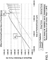
- FIG. 1 is a log-log graph (logarithmic y-axis, logarithmic x-axis) that shows the scaling of the acoustic radiation force, fluid drag force, and buoyancy force with particle radius. Calculations are done for a typical mammalian cell used in experiments. In the experiment, the mammalian cell had a density ( ⁇ p ) of 1,050 kg/m 3 and a cell sound speed ( C p ) of 1,550 m/s.
- the fluid in which the particle was flowed was water having a density ( ⁇ w ) of 1000 kg/m 3 , a fluid sound speed ( C f ) of 1500 m/s, and a flow rate ( V f ) of 4 cm/min.
- the experiment used 33 PZT-8 ultrasonic transducers driven at a frequency (f) of 2.2 MHz at a pressure (p) of 1 MPa.
- the gravity / buoyancy force is a particle volume dependent force, and is therefore negligible for particle sizes on the order of micron, but grows, and becomes significant for particle sizes on the order of hundreds of microns.
- the fluid drag force scales linearly with fluid velocity, and therefore typically exceeds the buoyancy force for micron sized particles, but is negligible for larger sized particles on the order of hundreds of microns.
- the acoustic radiation force scaling is different. When the particle size is small, Gor'kov's equation is accurate and the acoustic trapping force scales with the volume of the particle.
- the acoustic radiation force no longer increases with the cube of the particle radius, and will rapidly vanish at a certain critical particle size.
- the radiation force increases again in magnitude but with opposite phase (not shown in the graph). This pattern repeats for increasing particle sizes.
- FIG. 1 explains how small particles can be trapped continuously in a standing wave, grow into larger particles or clumps, and then continuously will rise or settle out because of enhanced buoyancy or gravity forces.
- the acoustophoretic separation technology of the present disclosure employs multi-dimensional ultrasonic acoustic standing waves, planar acoustic standing waves or combinations of planar and multidimensional acoustic standing waves (collectively referred to herein simple as acoustic standing waves) to trap particles or a secondary fluid in a volume of fluid containing said particles / secondary fluid.
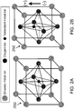
- FIG. 2A a first embodiment of a piezoelectric material 200 is shown.
- the piezoelectric material 200 is a perovskite crystal at a temperature above the Curie point.
- the piezoelectric material 200 is in the shape of a cubic lattice with a symmetrical arrangement of positive and negative charges.
- FIG. 2B shows a second embodiment of a piezoelectric material 250 .
- the piezoelectric material 250 is a perovskite crystal at a temperature below the Curie point.
- the piezoelectric material 250 is in the shape of a tetragonal (orthorhombic) lattice with an electric dipole.
- Both of the piezoelectric materials 200 , 250 depicted in FIG. 2A and FIG. 2B are comprised of divalent metal ion(s) (e.g., lead, barium), oxygen ion(s), and tetravalent metal ion(s) (e.g., titanium, zirconium).
- divalent metal ion(s) e.g., lead, barium
- oxygen ion(s) e.g., titanium, zirconium
- tetravalent metal ion(s) e.g., titanium, zirconium
- the Curie point is a critical temperature at which each perovskite crystal in a piezoelectric material exhibits a simple cubic symmetry with no dipole moment.
- each crystal has tetragonal or rhombohedral symmetry and a dipole moment. Adjoining dipoles form regions of local alignment are called domains.
- the alignment of the crystals gives a net dipole moment to the domain in the crystal and, as a result, generates a net polarization.
- the polarization is still random and thus there is no overall direction that the piezoelectric crystal will change in shape when an electrical impulse is applied.
- a strong, direct current electric field is applied to the crystal.
- the domains of the piezoelectric crystal most nearly aligned with the electric field expand at the expense of domains that are not aligned with the field, and the piezoelectric crystal expands in the direction of the strong electrical field.
- the electric field is removed, most of the dipoles are locked into a configuration of near alignment.
- the piezoelectric crystal now has a permanent polarization (i.e., the crystal can be considered "poled").
- the crystal upon supplying an electrical charge to the crystal, the crystal will expand and contract in the direction that it is now poled.
- a single frequency can be used to excite a multi-dimensional acoustic standing wave.
- a piezoelectric material having a non-planar (i.e., non-flat) face can be electrically excited by a single frequency to further enhance the expansion and contraction in the poled direction of the crystal, such that differential vibrations (as opposed to uniform vibrations) emanate from the surface of the non-planar face of the piezoelectric material to generate a multi-dimensional acoustic standing wave.
- a multi-dimensional acoustic standing wave can be generated as desired (e.g., with a desired strength, shape, intensity).
- FIG. 3 shows an example not forming part of the invention of such a piezoelectric material 300 in which a non-planar first face 310 of the piezoelectric material 300 is defined by a smooth function.
- the non-planar face 310 of the piezoelectric material 300 is poled in a direction 320 substantially perpendicular to a second face 330 of the piezoelectric material 300 .
- the non-planar face 310 and the second face 330 are located on opposite sides of the crystal.
- the second face is planar, and provides the reference against which the non-planarity of the first face 310 is determined.
- the first face 310 is formed from a series of peaks 312 and valleys 314 . The transition between the peaks and valleys is smooth.
- a smooth function is a function having a derivative that is continuous.
- a single electrode can be used on each side of the piezoelectric material.
- the electrode may be coated by several means, such as plating with electroless nickel or spray coating with a conductive coating, such as a silver-containing coating.
- the electrodes must be separated so that there is a positive terminal and a negative terminal to energize the piezoelectric material.
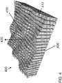
- FIG. 4 shows a second embodiment of a piezoelectric material 400 in which a non-planar first face 410 of the piezoelectric material 400 is defined by a stepped function.
- the non-planar face 410 of the piezoelectric material 400 is poled in a direction 420 substantially perpendicular to a second face 430 of the piezoelectric material 400 .
- a stepped function is a piecewise constant function.
- the overall shape of the first face 410 is made up of a series of smaller flat surfaces 412 , also referred to herein as facets.
- FIG. 5 shows a third embodiment of a piezoelectric material 500 in which a non-planar face 510 of the piezoelectric material 500 is defined by a stepped function. Yet again, the non-planar first face 510 of the piezoelectric material 500 is poled in a direction 520 substantially perpendicular to a second face 530 of the piezoelectric material 500 .
- the main difference between FIG. 4 and FIG. 5 is that the adjacent smaller flat surfaces 512 (i.e. facets) vary much more in their difference in height (relative to the second face 530 ).
- the reflector located on an opposite side of the acoustic chamber from the transducer / piezoelectric material can also have a non-planar surface, which can be likewise defined by a smooth or stepped function.
- the non-planar face of the transducer / piezoelectric material and the non-planar surface of the reflector may be described as being faceted, such as is depicted in FIG. 6 .
- the piezoelectric material 600 has a flat, planar first face 610
- the reflector 650 has a faceted surface 660 .
- the faceted surface 660 of the reflector 650 is defined by flat surfaces or facets 662 , similar to the facets 512 of the piezoelectric material 500 of FIG. 5 and the facets 412 of the piezoelectric material 400 of FIG. 4 . That is, as depicted in FIG. 6 , the facets 662 in the faceted surface 660 of the reflector 650 can be stepped, such that adjacent facets are located different distances from a first face 610 of the piezoelectric material 600 . For example, facet 670 is located distance L 1 from the first face 610 of the piezoelectric material 600 , while facet 680 is located distance L 2 from the first face 610 of the piezoelectric material 600 , with L 1 being greater than L 2 .
- the facets 662 may be dimensioned as desired.
- facet 670 typically has a width 672 selected to maximize the reflected energy.
- the distance between adjacent facets such as distance L 3 between facet 670 and facet 680 , is typically selected to minimize the distance between the director of a natural vibration mode of the piezoelectric material and adjacent facets.
- the distance between a facet and the first face 610 of the piezoelectric material 600 typically corresponds to a half wavelength to accommodate for all possible resonance conditions in the acoustic chamber.
- FIGS. 7A-7C depict various exemplary configurations of the faceted surface 660 of the reflector 650 .
- FIG. 7A shows a design in which the faceted surface 660 of the reflector 650 includes flat surfaces or facets 662 that extend along the length of the reflector 650 .
- the height of a given facet generally differs from the height of an adjacent facet by a fraction of the generated acoustic standing wave.
- the design in FIG. 7A implements a degenerated one-dimensional pattern of intermittent steps.
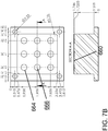
- FIG. 7B shows a design in which the faceted surface 660 of the reflector 650 includes wells 664 having flat bottoms 666 .
- the wells 664 are all of equal depth.
- the distribution of the wells 664 on the faceted surface 660 of the reflector 650 corresponds to the distribution of the 3x3 mode pattern emitted by the reflector 650 .
- the wells are distributed in a regular pattern along the faceted surface.
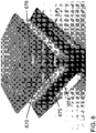
- FIG. 7C and FIG. 8 show a design in which the faceted surface 660 of the reflector 650 includes multiple facet clusters 668 .
- each facet cluster 668 is comprised of a pyramid-shaped group of five facets, with four outer facets 673 , 674 , 675 , 676 differing from a central facet 670 by a multiple of 0.1 wavelengths. That is, if the central facet 670 corresponds to the 0 position, the four outer facets 673 , 674 , 675 , 676 are deeper by 0.1, 0.2, 0.3, and 0.4 wavelengths, respectively.
- outer facet 673 is located 70 ⁇ m below the surface of the central facet 670
- outer facet 674 is located 140 ⁇ m below the surface of the central facet 670
- outer facet 675 is located 210 ⁇ m below the surface of the central facet 670
- outer facet 676 is located 240 ⁇ m below the surface of the central facet 670 .
- the distribution of the facet clusters 668 corresponds to the distribution of the 9x9 mode pattern reflected by the reflector, though it is to be understood that such a design could also be used with a 3x3 mode pattern. It is further contemplated that the pattern of the facets in the faceted surface 660 of the reflector 650 may influence the mode selection for various frequencies.
- the number of facets or facet levels within a single facet cluster is typically selected to ensure smooth adjustment to the changing resonance conditions within the acoustic chamber (i.e., more facets or facet levels for more gradual transitions), with the facets or facet levels differing from one another by a fraction of the acoustic wavelength, as previously explained.
- the number of facets or facet levels should, however, generally be limited to minimize the total number of facets, thereby increasing the reflecting area per facet.
- the piezoelectric material may likewise have a faceted front face, similar to the faceted surface of the reflector depicted in FIG. 6 and FIGS. 7A -7C .
- the first face of the piezoelectric material is faceted, while the surface of the reflector is generally kept planar or flat.
- FIG. 9 and FIG. 10 depict another exemplary embodiment of a faceted surface 660 of the reflector 650 .
- FIG. 9 shows the entire reflector
- FIG. 10 provides a magnified view of a portion of the faceted surface 660 of the reflector 650 .
- the surface is divided into multiple facets that provide four different heights.
- a dotted line is used to indicate the facet cluster 690 .
- the central facet 691 is surrounded by a second facet 692 , a third facet 693 , and a fourth facet 694 .
- the second facet 692 has approximately twice the surface area of the third facet or the fourth facet.
- the third facet 693 is the lowest of these facets, followed by the second facet 692 , then the fourth facet 694 , with the central facet 691 being the highest of these facets.
- the facets are generally illustrated as being surfaces with a square-shaped perimeter. This is not a requirement, and the facets may be of any suitable shape, e.g. rectangular, circular, etc.
- the operation of the acoustophoretic devices of the present disclosure includes generation of acoustic standing waves in an acoustic chamber.
- the acoustic standing waves can be at a fixed frequency throughout the period of operation, and the frequency may be selected to match the mode distribution of the piezoelectric material to the facet distribution of the reflector.
- Optimal cell separation is achieved under the resonance conditions at the maximal amplitude of the acoustic pressure for a fixed emitter power.
- the maximal acoustic pressure in turn leads to the maximal acoustic radiation force, which is the result of the acoustic field gradients, and to the most efficient cell trapping.
- particles e.g., cells
- the speed of sound may also change due to the change of temperature of the suspension.
- the temperature change may be a result of the acoustic operation or due to the change of the feed solution temperature.
- the resonance conditions can be changed also for different suspension compositions. These are most typical, but not all the possible, mechanisms of the resonance destruction.
- FIG. 11 graphically illustrates some of the advantages of using a reflector having a faceted surface over a flat, planar reflector.
- the lowest two lines i.e., the lines having square and diamond-shaped points
- the upper two lines i.e., the lines having triangular and X-shaped points
- the x-axis of FIG. 11 represents various operating frequencies in ten thousands of Hertz.
- FIG. 11 shows that for a yeast concentration of 1 x 10 6 cells/mL, the efficiency of a faceted reflector was noticeably greater than the efficiency of a flat, planar reflector.
- FIG. 12 graphically illustrates the efficiency of a faceted reflector versus the efficiency of a flat, planar reflector at a frequency of 2.185 MHz across a period of 80 minutes.
- the device is a self-tuning system capable of readjusting to maintain a strong multi-dimensional (e.g., three-dimensional) acoustic field regardless of the changing properties of the processed suspension, and capable of working at the same operation frequency.
- a reflector having a faceted surface improves the acoustophoretic device by shortening or completely eliminating the undesirable time periods during which the frequency of the device must be scanned and, therefore, out of tune.
- a reflector having a faceted surface also optimizes the performance at uneven cell mass distribution. As the cell density and concentration can be different along the paths between the piezoelectric material / transducer and the reflector at different positions across the resonator cross section, the resonance conditions can be different along these paths. With a reflector having a faceted surface, different facets are available to re-tune the resonator along these paths in accordance to these local conditions. This level of optimization does not exist in a flat transducer-flat reflector system, even with agile frequency tuning.
- the use of a reflector having a faceted surface suppresses the standing wave corresponding to the "piston" mode of the flat piezoelectric material / transducer regardless of the frequency. Therefore, the range of operation frequencies available with the reflector having a faceted surface is wider than with a flat transducer-flat reflector system.
- the differential vibrations of the non-planar face of the piezoelectric material allow for differential pressure waves to be generated from the non-planar face of the piezoelectric material using a single voltage input from the function generator and the amplifier into the piezoelectric material.
- This allows for the creation of a multi-dimensional acoustic standing wave and further allows for local wave fronts with varying amplitudes to come from the non-planar face of the piezoelectric material with a single frequency input to then generate the multi-dimensional standing wave in the fluid.
- the piezoelectric material and/or reflector may be non-symmetrical or asymmetric in shape. This refers to the shape of the piezoelectric material as defined by its perimeter. Put another way, the perimeter of the piezoelectric material forms an irregular polygon, or the piezoelectric material does not have any axis of symmetry.
- the piezoelectric crystal of FIG. 3 for example, is a square, which is symmetrical.
- piezoelectric material 1300 depicted in FIG. 13 has a trapezoidal shape with four different angles. Designing the piezoelectric material to have a non-symmetrical shape allows for an acoustic standing wave created by the piezoelectric material to generate trapping lines that are asymmetric.
- FIG. 14 shows four asymmetric excitation patterns generated on the face of a trapezoidal piezoelectric material at four different frequencies.
- the asymmetry of the piezoelectric material leads to generation of asymmetric trapping lines of particles inside the fluid, at different frequencies of excitation.
- This asymmetric field of trapping lines allows for less interference between adjacent trapping lines when continuous gravity separation of a secondary fluid or particulate from a host fluid is in operation.
- the trapping lines of the standing wave will be staggered in such a manner that the collected secondary fluid or particles in each trapping line interfere less with one another as they are gravitationally separated from the host fluid, compared to those generated by a symmetric piezoelectric material.
- the particles or secondary fluid collect at the nodes or anti-nodes of the acoustic standing wave, depending on the particles' or secondary fluid's acoustic contrast factor relative to the host fluid, forming clusters / clumps / agglomerates / coalesced droplets that continuously fall out of the acoustic standing wave when the clusters have grown to a size large enough to overcome the holding force of the acoustic standing wave (e.g. by coalescence or agglomeration) and the particle / secondary fluid density is higher than the host fluid, or to rise out of the acoustic standing wave when the particle / secondary fluid density is less than the host fluid.
- the acoustic radiation force is proportional to the particle volume (e.g. the cube of the radius) when the particle is small relative to the wavelength. It is proportional to frequency and the acoustic contrast factor. It also scales with acoustic energy (e.g. the square of the acoustic pressure amplitude).
- the sinusoidal spatial variation of the force is what drives the particles to the stable axial positions within the standing waves.
- the acoustic radiation force exerted on the particles is stronger than the combined effect of fluid drag force and buoyancy and gravitational force, the particle is trapped within the acoustic standing wave field. This results in concentration, agglomeration and/or coalescence of the trapped particles.
- Micron-sized particles e.g., bacteria, mammalian cells, micro-algae, metal particles, yeast, fungi, lipids, oil droplets, red blood cells, white blood cells, platelets, etc.
- Micron-sized particles e.g., bacteria, mammalian cells, micro-algae, metal particles, yeast, fungi, lipids, oil droplets, red blood cells, white blood cells, platelets, etc.
- the system parameters For the case of a suspension with several different particle sizes, it is possible by tuning of the system parameters to settle out the group of particles that are larger in size whereas the group of particles smaller in size can be kept in suspension. These two layers can then be harvested separately.
- a repeated process can then be used to fractionate groups of different sized particles according to size.
- the multi-dimensional acoustic standing waves generated by each transducer can be of different frequencies.
- acoustophoresis device is in the processing of bioreactor materials. It is important to be able to separate relatively larger cells and cell debris from the expressed materials that are in the host fluid.
- the expressed materials are composed of biomolecules such as recombinant proteins or monoclonal antibodies, and are the desired product to be recovered.
- acoustophoresis the separation of the cells and cell debris is very efficient and leads to very little loss of the expressed materials. This is an improvement over current filtration processes (depth filtration, tangential flow filtration, and the like), which show limited efficiencies at high cell densities, so that the loss of the expressed materials in the filter beds themselves can be up to 5% of the materials produced by the bioreactor.
- mammalian cell cultures including Chinese hamster ovary (CHO), NS0 hybridoma cells, baby hamster kidney (BHK) cells, insect cells, and human cells (e.g. T-cells, B-cells, stem cells, red blood cells), and living/biological cells in general has proven to be a very efficacious way of producing/expressing the recombinant proteins and monoclonal antibodies required of today's pharmaceuticals.
- the filtration of the mammalian cells and the mammalian cell debris through acoustophoresis aids in greatly increasing the yield of the bioreactor.
- the acoustophoresis process may also be coupled with a standard filtration process upstream or downstream, such as depth filtration, tangential flow filtration (TFF), or other physical filtration processes.
- Efficient separation has been demonstrated for CHO cells, T-cells, and yeast cells with separation efficiencies in excess of 90% and more for cell concentrations from as little as 50,000 cells per ml of fluid to 80 million cells per ml of fluid.
- the flow rates of the acoustic separation devices according to the current embodiments vary from 1 ml/min for smaller scale devices to in excess of 50 liter/hour for larger scale devices.
- the acoustic contrast factor is a function of the ratio of particle to fluid compressibility and particle to fluid density.
- Most cell types present a higher density and lower compressibility than the medium in which they are suspended, so that the acoustic contrast factor between the cells and the medium has a positive value.
- the axial acoustic radiation force (ARF) drives the cells, with a positive contrast factor, to the pressure nodal planes, whereas cells or other particles with a negative contrast factor are driven to the pressure anti-nodal planes.
- the radial or lateral component of the ARF is larger than the combined effect of fluid drag force and gravitational force.
- the radial or lateral component drives the cells/particles to specific locations (points) within these planes where they cluster, clump, agglomerate, or coalesce into larger groups, which will then continuously gravity separate from the fluid.
- the ultrasonic transducer(s) generate a three-dimensional or multi-dimensional acoustic standing wave in the fluid that exerts a lateral force on the suspended particles to accompany the axial force so as to increase the particle trapping and clumping capabilities of the standing wave.
- the technology disclosed in this application provides for a lateral force to be of the same order of magnitude as the axial force (i.e. a multi-dimensional acoustic standing wave).
- combinations of transducers that produce both multi-dimensional acoustic standing waves and planar standing waves are contemplated.
- a standing wave where the lateral force is of the same order of magnitude as the axial force is considered a "multi-dimensional acoustic standing wave.”
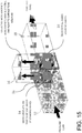
- FIG. 15 A diagrammatic representation of an acoustic chamber for removing oil or other lighter-than-water material is shown in FIG. 15 .
- Excitation frequencies typically in the range from hundreds of kHz to 10s of MHz are applied by transducer 10 .
- One or more standing waves are created between the transducer 10 and the reflector 11 .
- Incoming host fluid containing a secondary phase enters at inlet 12 .
- Microdroplets are trapped in standing waves at the pressure anti-nodes 14 where they agglomerate, aggregate, clump, or coalesce, and, in the case of buoyant material, float to the surface and are discharged via an effluent outlet 16 located above the flow path.
- Clarified fluid e.g. water
- the acoustophoretic separation technology can accomplish multi-component particle separation without any fouling at a much reduced cost.
- FIG. 16 A diagrammatic representation of an acoustic chamber for removing contaminants or other heavier-than-water material is shown in FIG. 16 .
- Excitation frequencies typically in the range from hundreds of kHz to 10s of MHz are applied by transducer 10 .
- Incoming contaminated fluid enters through inlet 13 .
- Contaminants are trapped in standing waves at the pressure nodes 15 where they agglomerate, aggregate, clump, or coalesce, and, in the case of heavier material, sink to the bottom collector and are discharged via an effluent outlet 17 located below the flow path. Clarified fluid is discharged at outlet 18 .
- the ultrasonic transducer and reflector are located on opposite sides of the acoustic chamber. In this way, one or more acoustic standing waves are created between the ultrasonic transducer and reflector.
- the multi-dimensional acoustic standing wave needed for particle collection is obtained by driving an ultrasonic transducer at a frequency that both generates the acoustic standing wave and excites a fundamental 3D vibration mode of the transducer piezoelectric element.
- the multi-dimensional acoustic standing wave may be generated by distinct modes of the piezoelectric element such as a 3x3 mode that would generate multidimensional acoustic standing waves.
- a multitude of multidimensional acoustic standing waves may also be generated by allowing the piezoelectric element to vibrate through many different mode shapes.
- the element would excite multiple modes such as a 0x0 mode (i.e. a piston mode) to a 1x1 (the fundamental mode), to 2x2, 1x3, 3x1, 3x3, and other higher order modes and then cycle back through the lower modes of the element (not necessarily in straight order).
- a 0x0 mode i.e. a piston mode
- 1x1 the fundamental mode
- 2x2, 1x3, 3x1, 3x3, and other higher order modes then cycle back through the lower modes of the element (not necessarily in straight order).
- This switching or dithering of the piezoelectric element between modes allows for various multi-dimensional wave shapes, along with a single piston mode shape, to be generated over a designated time.
- the scattering of the acoustic field off the particles results in a three dimensional acoustic radiation force, which acts as a three-dimensional trapping field.
- the acoustic radiation force is proportional to the particle volume (e.g. the cube of the radius) when the particle is small relative to the wavelength. It is proportional to frequency and the acoustic contrast factor. It also scales with acoustic energy (e.g. the square of the acoustic pressure amplitude).
- the acoustic radiation force exerted on the particles is stronger than the combined effect of fluid drag force and buoyancy and gravitational force, the particles are trapped within the acoustic standing wave field. This results in concentration, agglomeration and/or coalescence of the trapped particles. Relatively large solids of one material can thus be separated from smaller particles of a different material, the same material, and/or the host fluid through enhanced gravitational separation.
- the multi-dimensional standing wave generates acoustic radiation forces in both the axial direction (i.e., in the direction of the standing wave, between the transducer and the reflector, perpendicular to the flow direction) and the lateral direction (i.e., in the flow direction).
- the axial direction i.e., in the direction of the standing wave, between the transducer and the reflector, perpendicular to the flow direction
- the lateral direction i.e., in the flow direction
- the lateral acoustic radiation force then acts to move the concentrated particles towards the center of each planar node, resulting in agglomeration or clumping.
- the lateral acoustic radiation force component has to overcome fluid drag for such clumps of particles to continually grow and then drop out of the mixture due to gravity. Therefore, both the drop in drag per particle as the particle cluster increases in size, as well as the drop in acoustic radiation force per particle as the particle cluster grows in size, must be considered for the acoustic separator device to work effectively.
- the lateral force component and the axial force component of the multi-dimensional acoustic standing wave are of the same order of magnitude.
- the axial force is stronger than the lateral force, but the lateral force of a multi-dimensional acoustic standing wave is much higher than the lateral force of a planar standing wave, usually by two orders of magnitude or more.
- the transducers use a piezoelectric element, usually made of PZT-8 (lead zirconate titanate).
- PZT-8 lead zirconate titanate
- Such elements may have a 2,54 cm by 2,54 cm (1 inch by 1 inch) square shape with a thickness of 1 mm (nominal 2 MHz resonance frequency), and may also be of a larger size, such as a 2,54 cm by 7,62 cm (1 inch by 3 inch) shape with a 1 mm thickness, or smaller such as 1,27 cm by 1,27 cm (0.5 inch by 0.5 inch).
- the thickness controls the resonance frequency, as the resonance frequency is inversely proportional to thickness.
- Each ultrasonic transducer module can have only one piezoelectric element, or can have multiple elements that each act as a separate ultrasonic transducer and are either controlled by one or multiple amplifiers.
- the piezoelectric element(s) can be crystalline, semi-crystalline, or non-crystalline.
- the transducer(s) is/are used to create a pressure field that generates forces of the same order of magnitude both orthogonal to the standing wave direction (lateral) and in the standing wave direction (axial).
- FIG. 17 is a cross-sectional diagram of a conventional ultrasonic transducer.
- This transducer has a wear plate 50 at a bottom end, epoxy layer 52 , piezoelectric element 54 (e.g. a ceramic crystal made of, e.g. PZT), an epoxy layer 56 , and a backing layer 58 .
- piezoelectric element 54 e.g. a ceramic crystal made of, e.g. PZT
- an epoxy layer 56 attaches backing layer 58 to the piezoelectric element 54 .
- the entire assembly is contained in a housing 60 which may be made out of, for example, aluminum.
- An electrical adapter 62 provides connection for wires to pass through the housing and connect to leads (not shown) which attach to the piezoelectric element 54 .
- backing layers are designed to add damping and to create a broadband transducer with uniform displacement across a wide range of frequency and are designed to suppress excitation at particular vibrational eigen-modes.
- Wear plates are usually designed as impedance transformers to better match the characteristic impedance of the medium into which the transducer radiates.
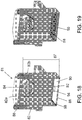
- FIG. 18 is a cross-sectional view of an ultrasonic transducer 81 of the present disclosure.
- Transducer 81 is shaped as a disc or a plate, and has an aluminum housing 82 .
- the piezoelectric element can be, e.g., a mass of perovskite ceramic crystals, each consisting of a small, tetravalent metal ion, usually titanium or zirconium, in a lattice of larger, divalent metal ions, usually lead or barium, and O2-ions.
- a PZT (lead zirconate titanate) crystal 86 defines the bottom end of the transducer, and is exposed from the exterior of the housing.
- the crystal is supported on its perimeter by a small elastic layer 98 , e.g. silicone or similar material, located between the crystal and the housing. Put another way, no wear layer is present.
- the crystal is an irregular polygon, and in further embodiments is an asymmetrical irregular polygon.
- Screws 88 attach an aluminum top plate 82a of the housing to the body 82b of the housing via threads.
- the top plate includes a connector 84 for powering the transducer.
- the top surface of the PZT crystal 86 is connected to a positive electrode 90 and a negative electrode 92 , which are separated by an insulating material 94 .
- the electrodes can be made from any conductive material, such as silver or nickel. Electrical power is provided to the PZT crystal 86 through the electrodes on the crystal. Note that the crystal 86 has no backing layer or epoxy layer. Put another way, there is an air gap 87 in the transducer between aluminum top plate 82a and the crystal 86 (i.e. the air gap is completely empty).
- a minimal backing 58 and/or wear plate 50 may be provided in some embodiments, as seen in FIG. 19 .
- the transducer design can affect performance of the system.
- a typical transducer is a layered structure with the piezoelectric element bonded to a backing layer and a wear plate. Because the transducer is loaded with the high mechanical impedance presented by the standing wave, the traditional design guidelines for wear plates, e.g., half wavelength thickness for standing wave applications or quarter wavelength thickness for radiation applications, and manufacturing methods may not be appropriate. Rather, in one embodiment of the present disclosure the transducers, there is no wear plate or backing, allowing the piezoelectric element to vibrate in one of its eigenmodes (i.e. near eigenfrequency) with a high Q-factor.
- the vibrating piezoelectric element such as, e.g., a ceramic crystal/disk, is directly exposed to the fluid flowing through the acoustic chamber.
- Removing the backing also permits the element to vibrate at higher order modes of vibration with little damping (e.g. higher order modal displacement).
- the element vibrates with a more uniform displacement, like a piston.
- Removing the backing allows the element to vibrate in a non-uniform displacement mode.
- the higher order the mode shape of the piezoelectric element the more nodal lines the element has.
- the higher order modal displacement of the element creates more trapping lines, although the correlation of trapping line to node is not necessarily one to one, and driving the element at a higher frequency will not necessarily produce more trapping lines.
- the piezoelectric element may have a backing that minimally affects the Q-factor of the crystal (e.g. less than 5%).
- the backing may be made of a substantially acoustically transparent material such as balsa wood, foam, or cork which allows the element to vibrate in a higher order mode shape and maintains a high Q-factor while still providing some mechanical support for the element.
- the backing layer may be a solid, or may be a lattice having holes through the layer, such that the lattice follows the nodes of the vibrating element in a particular higher order vibration mode, providing support at node locations while allowing the rest of the element to vibrate freely.
- the goal of the lattice work or acoustically transparent material is to provide support without lowering the Q-factor of the piezoelectric element or interfering with the excitation of a particular mode shape.
- Placing the piezoelectric element in direct contact with the fluid also contributes to the high Q-factor by avoiding the dampening and energy absorption effects of the epoxy layer and the wear plate.
- Other embodiments may have wear plates or a wear surface to prevent the PZT, which contains lead, contacting the host fluid. This may be desirable in, for example, biological applications such as separating blood. Such applications might use a wear layer such as chrome, electrolytic nickel, or electroless nickel. Chemical vapor deposition could also be used to apply a layer of poly(p-xylylene) (e.g. Parylene) or other polymers or polymer films. Organic and biocompatible coatings such as silicone or polyurethane are also usable as a wear surface.
- linear velocities through the devices of the present disclosure can be a minimum of 4 cm/min for separation of cells/particles, and can be as high as 1 cm/sec for separation of oil/water phases.
- the lateral force of the acoustic radiation force generated by the transducer can be increased by driving the transducer in higher order mode shapes, as opposed to a form of vibration where the piezoelectric element effectively moves as a piston having a uniform displacement.
- the acoustic pressure is proportional to the driving voltage of the transducer.
- the electrical power is proportional to the square of the voltage.
- the voltage signal can have a sinusoidal, triangular, pulsed, or similar waveform and can have a frequency of from about 100 kHz to about 20 MHz.
- the transducer is typically a thin piezoelectric plate, with electric field in the z-axis and primary displacement in the z-axis.
- the transducer is typically coupled on one side by air (i.e., the air gap within the transducer) and on the other side by the fluid mixture of the cell culture media.
- the types of waves generated in the plate are known as composite waves.
- a subset of composite waves in the piezoelectric plate is similar to leaky symmetric (also referred to as compressional or extensional) Lamb waves.
- the piezoelectric nature of the plate typically results in the excitation of symmetric Lamb waves.
- the waves are leaky because they radiate into the water layer, which result in the generation of the acoustic standing waves in the water layer. Lamb waves exist in thin plates of infinite extent with stress free conditions on its surfaces. Because the transducers of this embodiment are finite in nature, the actual modal displacements are more complicated.
- the transducers of the present disclosure are used to create a pressure field that generates acoustic radiation forces of the same order of magnitude both orthogonal to the standing wave direction and in the standing wave direction.
- the forces are roughly the same order of magnitude, particles of size 0.1 microns to 300 microns will be moved more effectively towards "trapping lines," so that the particles will not pass through the pressure field. Instead, the particles will remain within the acoustic chamber, from which they can advantageously be collected via specified outlets of the acoustophoretic device or otherwise recycled back to an associated bioreactor.
- the acoustophoretic devices and methods described herein are useful for separating a second fluid or particulate from a host fluid.
- the devices and methods of the present disclosure utilize higher order modal displacement of a piezoelectric material having a non-planar face, such that the piezoelectric material may be perturbed by a single excitation, yet still generate multi-dimensional acoustic standing waves.
Landscapes
- Engineering & Computer Science (AREA)
- Chemical & Material Sciences (AREA)
- Life Sciences & Earth Sciences (AREA)
- Mechanical Engineering (AREA)
- Chemical Kinetics & Catalysis (AREA)
- Zoology (AREA)
- Biotechnology (AREA)
- Health & Medical Sciences (AREA)
- Bioinformatics & Cheminformatics (AREA)
- Organic Chemistry (AREA)
- Wood Science & Technology (AREA)
- Biochemistry (AREA)
- Sustainable Development (AREA)
- General Engineering & Computer Science (AREA)
- General Health & Medical Sciences (AREA)
- Genetics & Genomics (AREA)
- Microbiology (AREA)
- Biomedical Technology (AREA)
- Physics & Mathematics (AREA)
- Acoustics & Sound (AREA)
- Multimedia (AREA)
- Physical Or Chemical Processes And Apparatus (AREA)
- Investigating Or Analyzing Materials By The Use Of Ultrasonic Waves (AREA)
- Piezo-Electric Transducers For Audible Bands (AREA)
Description
- This application claims priority to
U.S. Provisional Patent Application Serial No. 62/190,715, filed on July 9, 2015 - The present disclosure relates to the use of ultrasonically generated acoustic standing waves to achieve trapping, concentration, and separation of suspended-phase components and thereby remove such contaminants from a fluid medium such as water. The acoustic standing waves may be created by exciting the piezoelectric crystal of an ultrasonic transducer.
- Piezoelectric crystals may be composed of any material that is able to generate a piezoelectric effect, i.e. vibrate when subjected to an external voltage. A conventional material that is used to make piezoelectric crystals is lead zirconate titanate (PZT). Piezoelectric ceramics are traditionally a mass of perovskite ceramic crystals composed of a small, tetravalent metal ion (e.g., titanium, zirconium) in a lattice of larger, divalent metal ions (e.g., lead, barium) and oxygen ions.
- A piezoelectric PZT crystal can be made by mixing fine powders of the component metal oxides in specific proportions. This mixture is then heated to form a uniform powder. An organic binder is mixed with the metal oxides and formed into desired shapes (e.g., plates, rods, discs). The formed materials are heated at high temperatures that sinter the mixture and form a dense crystalline structure. The sintered parts are then cooled and subsequently shaped or trimmed to desired specifications. Electrodes are applied to the appropriate surfaces of the PZT crystal using processes such as electroless nickel plating or a silver/glass bead mixture coating that is heated and fused on the surface of the crystal.
- Exposing the piezoelectric crystal to an electric charge (i.e. voltage) either in air or a liquid fluid generates pressure waves. A function generator may be used to apply a specific frequency or group of frequencies to the piezoelectric crystal such that the pressure waves have a specific frequency. An amplifier may be used to apply higher voltages to the piezoelectric crystal at the frequencies generated by the function generator. Conventionally, the face of the piezoelectric crystal is flat and thus the waves generated from the piezoelectric crystal are uniform across the face of the crystal.
- A flat-faced piezoelectric crystal can be perturbed in a multi-mode fashion so as to generate multi-dimensional acoustic standing waves. These higher order modes of the piezoelectric crystal allow for multiple trapping lines to be formed in the acoustic standing wave, thus forming a multi-dimensional acoustic standing wave. The document
US 2014/0377834 A1 describes a method of using an acoustic standing wave to separate components from a multi-component fluid, such as animal cells from fluid-cell mixture, in a fluid flow scheme with an acoustophoresis device. For example, the flow scheme and device allows for trapping of falling cells as the cells coalesce, agglomerate, and the weight of the agglomerated mass overcomes the drag and ultrasonic standing wave forces in the device. It is generally mentioned that a reflector of the acoustophoresis device may have a non-planar surface. - It would be desirable to provide a piezoelectric crystal that can be perturbed by a single excitation, yet still generate a multi-dimensional acoustic standing wave(s) and improved tuning.
- This object is attained by the combination of features of
claim 1 or by the combination of features ofclaim 4. The present disclosure relates, in various embodiments, to acoustophoretic devices and methods of separating a second fluid or a particulate from a host fluid. Briefly, a multi-dimensional acoustic standing wave(s) emanating from a non-planar face of a piezoelectric material is used to continuously trap the second fluid or particulate, which then agglomerates, aggregates, clumps, or coalesces together, and subsequently rises or settles out of the host fluid due to buoyancy or gravity forces, and exits the acoustic chamber. The non-planar piezoelectric material only needs to be exposed to a single frequency, rather than a group of frequencies, to generate a multi-dimensional acoustic standing wave. - Disclosed in various embodiments herein are acoustophoretic devices, comprising: an acoustic chamber having at least one inlet and at least one outlet; at least one ultrasonic transducer located on a wall of the acoustic chamber; and a reflector located on a wall on the opposite side of the acoustic chamber from the at least one ultrasonic transducer. The at least one ultrasonic transducer includes a piezoelectric material driven by a voltage signal to create a multi-dimensional acoustic standing wave in the acoustic chamber emanating from the piezoelectric material. The piezoelectric material and/or the reflector includes a non-planar surface, wherein the non-planar surface is a faceted surface.
- In certain embodiments, the faceted surface of the piezoelectric material is poled in a direction substantially perpendicular to a second face of the piezoelectric material. The faceted surface of the piezoelectric material can be defined by a step function.
- In certain embodiments, the reflector also has a faceted surface which can be defined by a step function.
- In certain embodiments, the piezoelectric material may be planar and the reflector includes the faceted surface.
- The at least one ultrasonic transducer can have a non-symmetrical shape, such as a trapezoidal shape. The reflector can also have a non-symmetrical shape, such as a trapezoidal shape.
- Also disclosed herein are methods for separating a second fluid or a particulate from a host fluid. The methods comprise flowing a mixture of the host fluid and the second fluid or particulate through an acoustophoretic device. The acoustophoretic device comprises an acoustic chamber having at least one inlet and at least one outlet; at least one ultrasonic transducer located on a wall of the acoustic chamber; and a reflector located on a wall on the opposite side of the acoustic chamber from the at least one ultrasonic transducer. The at least one ultrasonic transducer includes a piezoelectric material driven by a voltage signal to create a multi-dimensional acoustic standing wave in the acoustic chamber emanating from the piezoelectric material. The methods further comprise sending a voltage signal to drive the at least one ultrasonic transducer to create the multi-dimensional acoustic standing wave in the acoustic chamber such that the second fluid or particulate is continuously trapped in the standing wave, and then agglomerates, aggregates, clumps, or coalesces together, and continuously rises or settles out of the host fluid due to enhanced buoyancy or gravity forces, and exits the acoustic chamber. The piezoelectric material and/or the reflector includes a non-planar surface, wherein the non-planar surface is a faceted surface.
- The voltage signal can be a sinusoidal, triangular, pulsed or similar waveform. The voltage signal can have a frequency of from about 100 kHz to about 20 MHz.
- In certain embodiments, the mixture of the host fluid and the second fluid or particulate is continuously flowed through the acoustic chamber. The second fluid or particulate can include at least one cell selected from the group consisting of CHO cells, T-cells, and yeast cells. Flow rates through the acoustic chamber can be from about 1 mL per minute to about 50 liters per hour. The methods and devices of the present disclosure may be capable of separation efficiencies of 90% and more for cell concentrations from as low as 50,000 cells per milliliter of fluid to 80,000,000 cells per milliliter of fluid.
- Separation of materials may also include particulates separated from a primary fluid. This would include microspheres, microbubbles, microcarriers and the like. These materials may be solid or hollow and have a positive or negative contrast factor.
- In one embodiment, the faceted surface of the reflector can include a plurality of facet clusters or a plurality of wells.
- In particular embodiments, the multi-dimensional standing wave results in an acoustic radiation force having an axial force component and a lateral force component that are the same order of magnitude. In an example not forming part of the invention, the acoustic standing wave may be a multi-dimensional acoustic standing wave (e.g., a three-dimensional acoustic standing wave). Examples of such multi-dimensional acoustic standing waves can be found in commonly owned
U.S. Patent No. 9,228,183 - These and other non-limiting characteristics are more particularly described below.
- The following is a brief description of the drawings, which are presented for the purposes of illustrating the exemplary embodiments disclosed herein and not for the purposes of limiting the same.
-
FIG. 1 is a graph showing the relationship of the acoustic radiation force, gravity / buoyancy force, and Stokes' drag force to particle size. The horizontal axis is in microns (µm) and the vertical axis is in Newtons (N). -
FIG. 2A illustrates a first embodiment of a piezoelectric material according to the present disclosure. The piezoelectric material is a perovskite crystal at a temperature above the Curie point. -
FIG. 2B illustrates a second embodiment of a piezoelectric material according to the present disclosure. The piezoelectric material is a perovskite crystal at a temperature below the Curie point. -
FIG. 3 illustrates a first example not forming part of the invention of a non-planar face of a piezoelectric material. The non-planar face of the piezoelectric material is defined by a smooth function. -
FIG. 4 illustrates a second embodiment of a non-planar face of a piezoelectric material according to the present disclosure. The non-planar face of the piezoelectric material is defined by a stepped function formed by facets. -
FIG. 5 illustrates a third embodiment of a non-planar face of a piezoelectric material according to the present disclosure. The non-planar face of the piezoelectric material is defined by a stepped function formed by facets. -
FIG. 6 illustrates a cross-sectional view of an acoustic chamber of an acoustophoretic device according to the present disclosure. The device includes a piezoelectric material having a planar first face and a reflector having a faceted surface. -
FIG. 7A illustrates a first exemplary configuration of the faceted surface of the reflector ofFIG. 6 . -
FIG. 7B illustrates a second exemplary configuration of the faceted surface of the reflector ofFIG. 6 . -
FIG. 7C illustrates a third exemplary configuration of the faceted surface of the reflector ofFIG. 6 . -
FIG. 8 illustrates a magnified view of a facet cluster of the faceted surface ofFIG. 7C , showing the height differential between a central facet and four surrounding outer facets. -
FIG. 9 illustrates a fourth exemplary configuration of the faceted surface of the reflector ofFIG. 6 . -
FIG. 10 illustrates a magnified view of the faceted surfaces depicted inFIG. 9 .FIG. 11 is a graph illustrating the separation efficiency of a faceted reflector versus a flat, planar reflector at varied impedance levels. The left-hand y-axis is impedance in thousands of kg * S-1 * m-2 (Rayls). The two lines marked as "flat reflector" and "faceted reflector" are read against the left-hand y-axis. The right-hand y-axis is efficiency. The points labeled "1 mission" and "1e6 flat" (triangular and X-shaped points) are read against the right-hand y-axis. The x-axis is in units of ten thousand Hertz. -
FIG. 12 is a graph illustrating the separation efficiency of a faceted reflector versus a flat, planar reflector over time at a frequency of 2.185 MHz and two different powers (5W and 10W). -
FIG. 13 illustrates a third embodiment of a piezoelectric material according to the present disclosure. The piezoelectric material has a non-symmetrical, trapezoidal shape. -
FIG. 14 illustrates the non-planar face of the trapezoidal piezoelectric material ofFIG. 13 upon which asymmetric excitation patterns are generated at four different frequencies. - In
FIG. 14 , the top left picture is at a frequency of 2.217 MHz. The right-hand scale is in units of 10-9, and ranges from 0.55 to 1 in intervals of 0.05. The maximum value is 2.25x10⁻⁹, and the minimum value is 2.18x10⁻¹¹. - In
FIG. 14 , the top right picture is at a frequency of 2.302 MHz. The right-hand scale is in units of 10-1, and ranges from 3 to 6 in intervals of 0.5. The maximum value is 1.38x10⁻⁹, and the minimum value is 1.64x10⁻¹¹. - In
FIG. 14 , the bottom left picture is at a frequency of 2.32 MHz. The right-hand scale is in units of 10-1, and ranges from 2.5 to 6 in intervals of 0.5. The maximum value is 1.11x10⁻⁹, and the minimum value is 1.4x10⁻¹¹. - In
FIG. 14 , the bottom right picture is at a frequency of 2.34 MHz. The right-hand scale is in units of 10-1, and ranges from 3 to 5 in intervals of 0.5. The maximum value is 9.23x10⁻¹⁰, and the minimum value is 8.98x10⁻¹². -
FIG. 15 is a diagram illustrating an acoustophoretic separation method according to the present disclosure for a second fluid or particle less dense than a host fluid. -
FIG. 16 is a diagram illustrating an acoustophoretic separation method according to the present disclosure for a second fluid or particle denser than a host fluid. -
FIG. 17 is a cross-sectional diagram of a conventional ultrasonic transducer. -
FIG. 18 is a cross-sectional diagram of an ultrasonic transducer according to the present disclosure. An air gap is present within the transducer, and no backing layer or wear plate is present. -
FIG. 19 is a cross-sectional diagram of an ultrasonic transducer according to the present disclosure. An air gap is present within the transducer, and a backing layer and wear plate are present. - The present disclosure may be understood more readily by reference to the following detailed description of desired embodiments and the examples included therein. In the following specification and the claims which follow, reference will be made to a number of terms which shall be defined to have the following meanings.
- Although specific terms are used in the following description for the sake of clarity, these terms are intended to refer only to the particular structure of the embodiments selected for illustration in the drawings, and are not intended to define or limit the scope of the disclosure. In the drawings and the following description below, it is to be understood that like numeric designations refer to components of like function.
- The singular forms "a," "an," and "the" include plural referents unless the context clearly dictates otherwise.
- The term "comprising" is used herein as requiring the presence of the named component and allowing the presence of other components. The term "comprising" should be construed to include the term "consisting of", which allows the presence of only the named component, along with any impurities that might result from the manufacture of the named component.
- Numerical values should be understood to include numerical values which are the same when reduced to the same number of significant figures and numerical values which differ from the stated value by less than the experimental error of conventional measurement technique of the type described in the present application to determine the value.
- All ranges disclosed herein are inclusive of the recited endpoint and independently combinable (for example, the range of "from 2 grams to 10 grams" is inclusive of the endpoints, 2 grams and 10 grams, and all the intermediate values). The endpoints of the ranges and any values disclosed herein are not limited to the precise range or value; they are sufficiently imprecise to include values approximating these ranges and/or values.
- The modifier "about" used in connection with a quantity is inclusive of the stated value and has the meaning dictated by the context. When used in the context of a range, the modifier "about" should also be considered as disclosing the range defined by the absolute values of the two endpoints. For example, the range of "from about 2 to about 10" also discloses the range "from 2 to 10." The term "about" may refer to plus or minus 10% of the indicated number. For example, "about 10%" may indicate a range of 9% to 11%, and "about 1" may mean from 0.9-1.1.
- It should be noted that many of the terms used herein are relative terms. For example, the terms "upper" and "lower" are relative to each other in location, i.e. an upper component is located at a higher elevation than a lower component in a given orientation, but these terms can change if the device is flipped. The terms "inlet" and "outlet" are relative to a fluid flowing through them with respect to a given structure, e.g. a fluid flows through the inlet into the structure and flows through the outlet out of the structure. The terms "upstream" and "downstream" are relative to the direction in which a fluid flows through various components, i.e. the flow fluids through an upstream component prior to flowing through the downstream component. It should be noted that in a loop, a first component can be described as being both upstream of and downstream of a second component.
- The terms "horizontal" and "vertical" are used to indicate direction relative to an absolute reference, i.e. ground level. However, these terms should not be construed to require structures to be absolutely parallel or absolutely perpendicular to each other. For example, a first vertical structure and a second vertical structure are not necessarily parallel to each other. The terms "top" and "bottom" or "base" are used to refer to surfaces where the top is always higher than the bottom/base relative to an absolute reference, i.e. the surface of the earth. The terms "upwards" and "downwards" are also relative to an absolute reference; upwards is always against the gravity of the earth.
- The term "parallel" should be construed in its lay sense of two surfaces that maintain a generally constant distance between them, and not in the strict mathematical sense that such surfaces will never intersect when extended to infinity.
- The present application refers to "the same order of magnitude." Two numbers are of the same order of magnitude if the quotient of the larger number divided by the smaller number is a value of at least 1 and less than 10.
- Acoustophoresis is the separation of particles and secondary fluids from a primary or host fluid using high-intensity acoustic standing waves, and without the use of membranes or physical size exclusion filters. It has been known that high intensity standing waves of sound can exert forces on particles in a fluid when there is a differential in both density and/or compressibility, otherwise known as the acoustic contrast factor. The pressure profile in a standing wave contains areas of local minimum pressure amplitudes at its nodes and local maxima at its anti-nodes. Depending on the density and compressibility of the particles, they will be trapped at the nodes or anti-nodes of the standing wave. Generally, the higher the frequency of the standing wave, the smaller the particles that can be trapped due the pressure of the standing wave.
- When acoustic standing waves propagate in liquids, the fast oscillations may generate a non-oscillating force on particles suspended in the liquid or on an interface between liquids. This force is known as the acoustic radiation force. The force originates from the non-linearity of the propagating wave. As a result of the non-linearity, the wave is distorted as it propagates and the time-averages are nonzero. By serial expansion (according to perturbation theory), the first non-zero term will be the second-order term, which accounts for the acoustic radiation force. The acoustic radiation force on a particle, or a cell, in a fluid suspension is a function of the difference in radiation pressure on either side of the particle or cell. The physical description of the radiation force is a superposition of the incident wave and a scattered wave, in addition to the effect of the non-rigid particle oscillating with a different speed compared to the surrounding medium thereby radiating a wave. The following equation presents an analytical expression for the acoustic radiation force on a particle, or cell, in a fluid suspension in a planar standing wave.

- In a typical experiment, the system is operated at a voltage such that the particles are trapped in the ultrasonic standing wave, i.e., remain in a stationary position. The axial component of the acoustic radiation force drives the particles, with a positive contrast factor, to the pressure nodal planes, whereas particles with a negative contrast factor are driven to the pressure anti-nodal planes. The radial or lateral component of the acoustic radiation force is the force that traps the particle. It therefore must be larger than the combined effect of fluid drag force and gravitational force. For small particles or emulsions, the drag force FD can be expressed as:


- For a particle to be trapped in the ultrasonic standing wave, the force balance on the particle must be zero, and therefore an expression for lateral acoustic radiation force FLRF can be found, which is given by:

- For a particle of known size and material property, and for a given flow rate, this equation can be used to estimate the magnitude of the lateral acoustic radiation force.
- The theoretical model that is used to calculate the acoustic radiation force is the formulation developed by Gor'kov, where the primary acoustic radiation force FR is defined as a function of a field potential U, FR = -∇ (U), where the field potential U is defined as


- For a one dimensional standing wave, where the acoustic pressure is expressed as


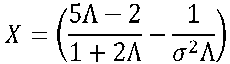
- Particles with a positive contrast factor will be driven to the pressure nodal planes, and particles with a negative contrast factor will be driven to the pressure anti-nodal planes. In this way, the generation of a multi-dimensional acoustic standing wave in an acoustic chamber results in the creation of tightly packed clusters of particles in the acoustic chamber, typically corresponding to the location of the pressure nodes or anti-nodes in the standing wave depending on acoustic contrast factor.
- Gork'ov's model is for a single particle in a standing wave and is limited to particle sizes that are small with respect to the wavelength of the sound fields in the fluid and the particle. It also does not take into account the effect of viscosity of the fluid and the particle on the radiation force. As a result, this model cannot be used for macro-scale ultrasonic separators since particle clusters can grow quite large.
-
FIG. 1 is a log-log graph (logarithmic y-axis, logarithmic x-axis) that shows the scaling of the acoustic radiation force, fluid drag force, and buoyancy force with particle radius. Calculations are done for a typical mammalian cell used in experiments. In the experiment, the mammalian cell had a density (ρp) of 1,050 kg/m3 and a cell sound speed (Cp ) of 1,550 m/s. The fluid in which the particle was flowed was water having a density (ρw) of 1000 kg/m3, a fluid sound speed (Cf ) of 1500 m/s, and a flow rate (Vf ) of 4 cm/min. The experiment used 33 PZT-8 ultrasonic transducers driven at a frequency (f) of 2.2 MHz at a pressure (p) of 1 MPa. As explained above, the gravity / buoyancy force is a particle volume dependent force, and is therefore negligible for particle sizes on the order of micron, but grows, and becomes significant for particle sizes on the order of hundreds of microns. The fluid drag force scales linearly with fluid velocity, and therefore typically exceeds the buoyancy force for micron sized particles, but is negligible for larger sized particles on the order of hundreds of microns. The acoustic radiation force scaling is different. When the particle size is small, Gor'kov's equation is accurate and the acoustic trapping force scales with the volume of the particle. Eventually, when the particle size grows, the acoustic radiation force no longer increases with the cube of the particle radius, and will rapidly vanish at a certain critical particle size. For further increases of particle size, the radiation force increases again in magnitude but with opposite phase (not shown in the graph). This pattern repeats for increasing particle sizes. - Initially, when a suspension is flowing through the system with primarily small micron sized particles, it is necessary for the acoustic radiation force to balance the combined effect of fluid drag force and buoyancy force for a particle to be trapped in the standing wave. In
FIG. 1 , this happens for a particle size of about 3.5 micron, labeled as Rc1. The graph then indicates that all larger particles will be trapped as well. Therefore, when small particles are trapped in the standing wave, particles coalescence / clumping / aggregation / agglomeration takes place, resulting in continuous growth of effective particle size. As the particle size grows, the acoustic radiation force reflects off the particle, such that large particles will cause the acoustic radiation force to decrease. Particle size growth continues until the buoyancy force becomes dominant, which is indicated by a second critical particle size, Rc2, at which size the particles will rise or sink, depending on their relative density with respect to the host fluid. Thus,FIG. 1 explains how small particles can be trapped continuously in a standing wave, grow into larger particles or clumps, and then continuously will rise or settle out because of enhanced buoyancy or gravity forces. - The models that were implemented in the present disclosure are based on the theoretical work of Yurii Ilinskii and Evgenia Zabolotskaya as described in AIP Conference Proceedings, Vol. 1474-1, pp. 255-258 (2012). These models also include the effect of fluid and particle viscosity, and therefore are a more accurate calculation of the acoustic radiation force.
- The acoustophoretic separation technology of the present disclosure employs multi-dimensional ultrasonic acoustic standing waves, planar acoustic standing waves or combinations of planar and multidimensional acoustic standing waves (collectively referred to herein simple as acoustic standing waves) to trap particles or a secondary fluid in a volume of fluid containing said particles / secondary fluid.
- Turning now to
FIG. 2A , a first embodiment of apiezoelectric material 200 is shown. In the embodiment depicted inFIG. 2A , thepiezoelectric material 200 is a perovskite crystal at a temperature above the Curie point. Thepiezoelectric material 200 is in the shape of a cubic lattice with a symmetrical arrangement of positive and negative charges.FIG. 2B shows a second embodiment of apiezoelectric material 250. In the embodiment depicted inFIG. 2B , thepiezoelectric material 250 is a perovskite crystal at a temperature below the Curie point. Thepiezoelectric material 250 is in the shape of a tetragonal (orthorhombic) lattice with an electric dipole. Both of thepiezoelectric materials FIG. 2A and FIG. 2B are comprised of divalent metal ion(s) (e.g., lead, barium), oxygen ion(s), and tetravalent metal ion(s) (e.g., titanium, zirconium). The dipole expansion and contraction of thepiezoelectric materials FIG. 2A and FIG. 2B allow for the piezoelectric effect to occur, resulting in the generation of pressure waves. - The Curie point is a critical temperature at which each perovskite crystal in a piezoelectric material exhibits a simple cubic symmetry with no dipole moment. However, at temperatures below the Curie point, such as is depicted in
FIG. 2B , each crystal has tetragonal or rhombohedral symmetry and a dipole moment. Adjoining dipoles form regions of local alignment are called domains. The alignment of the crystals gives a net dipole moment to the domain in the crystal and, as a result, generates a net polarization. The polarization, however, is still random and thus there is no overall direction that the piezoelectric crystal will change in shape when an electrical impulse is applied. - In operation, a strong, direct current electric field, usually at a temperature slightly below the Curie point, is applied to the crystal. Through this poling (polarization) treatment, the domains of the piezoelectric crystal most nearly aligned with the electric field expand at the expense of domains that are not aligned with the field, and the piezoelectric crystal expands in the direction of the strong electrical field. When the electric field is removed, most of the dipoles are locked into a configuration of near alignment. The piezoelectric crystal now has a permanent polarization (i.e., the crystal can be considered "poled"). Thus, upon supplying an electrical charge to the crystal, the crystal will expand and contract in the direction that it is now poled.
- In a conventional flat / planar piezoelectric surface, a single frequency can be used to excite a multi-dimensional acoustic standing wave. In accordance with the present disclosure, it has been found that a piezoelectric material having a non-planar (i.e., non-flat) face can be electrically excited by a single frequency to further enhance the expansion and contraction in the poled direction of the crystal, such that differential vibrations (as opposed to uniform vibrations) emanate from the surface of the non-planar face of the piezoelectric material to generate a multi-dimensional acoustic standing wave. Through proper shaping of the non-planar surface, a multi-dimensional acoustic standing wave can be generated as desired (e.g., with a desired strength, shape, intensity).
-
FIG. 3 shows an example not forming part of the invention of such apiezoelectric material 300 in which a non-planarfirst face 310 of thepiezoelectric material 300 is defined by a smooth function. In this way, thenon-planar face 310 of thepiezoelectric material 300 is poled in adirection 320 substantially perpendicular to asecond face 330 of thepiezoelectric material 300. In thepiezoelectric material 300 depicted inFIG. 3 , thenon-planar face 310 and thesecond face 330 are located on opposite sides of the crystal. The second face is planar, and provides the reference against which the non-planarity of thefirst face 310 is determined. As seen here, thefirst face 310 is formed from a series ofpeaks 312 andvalleys 314. The transition between the peaks and valleys is smooth. A smooth function is a function having a derivative that is continuous. - A single electrode can be used on each side of the piezoelectric material. The electrode may be coated by several means, such as plating with electroless nickel or spray coating with a conductive coating, such as a silver-containing coating. The electrodes must be separated so that there is a positive terminal and a negative terminal to energize the piezoelectric material.
- In contrast to
FIG. 3 ,FIG. 4 shows a second embodiment of apiezoelectric material 400 in which a non-planarfirst face 410 of thepiezoelectric material 400 is defined by a stepped function. Again, thenon-planar face 410 of thepiezoelectric material 400 is poled in adirection 420 substantially perpendicular to asecond face 430 of thepiezoelectric material 400. A stepped function is a piecewise constant function. As seen here, the overall shape of thefirst face 410 is made up of a series of smallerflat surfaces 412, also referred to herein as facets. -
FIG. 5 shows a third embodiment of apiezoelectric material 500 in which anon-planar face 510 of thepiezoelectric material 500 is defined by a stepped function. Yet again, the non-planarfirst face 510 of thepiezoelectric material 500 is poled in adirection 520 substantially perpendicular to asecond face 530 of thepiezoelectric material 500. The main difference betweenFIG. 4 andFIG. 5 is that the adjacent smaller flat surfaces 512 (i.e. facets) vary much more in their difference in height (relative to the second face 530). - It is also contemplated that the reflector located on an opposite side of the acoustic chamber from the transducer / piezoelectric material can also have a non-planar surface, which can be likewise defined by a smooth or stepped function. The non-planar face of the transducer / piezoelectric material and the non-planar surface of the reflector may be described as being faceted, such as is depicted in
FIG. 6 . InFIG. 6 , thepiezoelectric material 600 has a flat, planarfirst face 610, and thereflector 650 has afaceted surface 660. Thefaceted surface 660 of thereflector 650 is defined by flat surfaces orfacets 662, similar to thefacets 512 of thepiezoelectric material 500 ofFIG. 5 and thefacets 412 of thepiezoelectric material 400 ofFIG. 4 . That is, as depicted inFIG. 6 , thefacets 662 in thefaceted surface 660 of thereflector 650 can be stepped, such that adjacent facets are located different distances from afirst face 610 of thepiezoelectric material 600. For example,facet 670 is located distance L1 from thefirst face 610 of thepiezoelectric material 600, whilefacet 680 is located distance L2 from thefirst face 610 of thepiezoelectric material 600, with L1 being greater than L2 . It is to be understood that thefacets 662 may be dimensioned as desired. For example,facet 670 typically has awidth 672 selected to maximize the reflected energy. Similarly, the distance between adjacent facets, such as distance L3 betweenfacet 670 andfacet 680, is typically selected to minimize the distance between the director of a natural vibration mode of the piezoelectric material and adjacent facets. The distance between a facet and thefirst face 610 of the piezoelectric material 600 (e.g., distance L1 forfacet 670 and distance L2 for facet 680) typically corresponds to a half wavelength to accommodate for all possible resonance conditions in the acoustic chamber. - As will be appreciated by those skilled in the art, the
facets 662 can be arranged as desired to create an acoustic standing wave having a desired mode pattern.FIGS. 7A-7C depict various exemplary configurations of thefaceted surface 660 of thereflector 650. For example,FIG. 7A shows a design in which thefaceted surface 660 of thereflector 650 includes flat surfaces orfacets 662 that extend along the length of thereflector 650. The height of a given facet generally differs from the height of an adjacent facet by a fraction of the generated acoustic standing wave. The design inFIG. 7A implements a degenerated one-dimensional pattern of intermittent steps. -
FIG. 7B shows a design in which thefaceted surface 660 of thereflector 650 includeswells 664 havingflat bottoms 666. In the exemplary embodiment ofFIG. 7B , thewells 664 are all of equal depth. The distribution of thewells 664 on thefaceted surface 660 of thereflector 650 corresponds to the distribution of the 3x3 mode pattern emitted by thereflector 650. The wells are distributed in a regular pattern along the faceted surface. - Finally,
FIG. 7C andFIG. 8 show a design in which thefaceted surface 660 of thereflector 650 includesmultiple facet clusters 668. In this exemplary embodiment, eachfacet cluster 668 is comprised of a pyramid-shaped group of five facets, with fourouter facets central facet 670 by a multiple of 0.1 wavelengths. That is, if thecentral facet 670 corresponds to the 0 position, the fourouter facets central facet 670 inFIG. 8 corresponds to position 0,outer facet 673 is located 70 µm below the surface of thecentral facet 670,outer facet 674 is located 140 µm below the surface of thecentral facet 670,outer facet 675 is located 210 µm below the surface of thecentral facet 670, andouter facet 676 is located 240 µm below the surface of thecentral facet 670. The distribution of thefacet clusters 668 corresponds to the distribution of the 9x9 mode pattern reflected by the reflector, though it is to be understood that such a design could also be used with a 3x3 mode pattern. It is further contemplated that the pattern of the facets in thefaceted surface 660 of thereflector 650 may influence the mode selection for various frequencies. The number of facets or facet levels within a single facet cluster is typically selected to ensure smooth adjustment to the changing resonance conditions within the acoustic chamber (i.e., more facets or facet levels for more gradual transitions), with the facets or facet levels differing from one another by a fraction of the acoustic wavelength, as previously explained. The number of facets or facet levels should, however, generally be limited to minimize the total number of facets, thereby increasing the reflecting area per facet. As will be appreciated by those skilled in the art, the piezoelectric material may likewise have a faceted front face, similar to the faceted surface of the reflector depicted inFIG. 6 andFIGS. 7A -7C. In such embodiments, the first face of the piezoelectric material is faceted, while the surface of the reflector is generally kept planar or flat. -
FIG. 9 andFIG. 10 depict another exemplary embodiment of afaceted surface 660 of thereflector 650.FIG. 9 shows the entire reflector, whileFIG. 10 provides a magnified view of a portion of thefaceted surface 660 of thereflector 650. As best seen inFIG. 10 , the surface is divided into multiple facets that provide four different heights. A dotted line is used to indicate thefacet cluster 690. Thecentral facet 691 is surrounded by asecond facet 692, athird facet 693, and afourth facet 694. Thesecond facet 692 has approximately twice the surface area of the third facet or the fourth facet. Thethird facet 693 is the lowest of these facets, followed by thesecond facet 692, then thefourth facet 694, with thecentral facet 691 being the highest of these facets. - It is noted that in
FIGS. 4-10 , the facets are generally illustrated as being surfaces with a square-shaped perimeter. This is not a requirement, and the facets may be of any suitable shape, e.g. rectangular, circular, etc. - As will be explained in greater detail herein, the operation of the acoustophoretic devices of the present disclosure includes generation of acoustic standing waves in an acoustic chamber. The acoustic standing waves can be at a fixed frequency throughout the period of operation, and the frequency may be selected to match the mode distribution of the piezoelectric material to the facet distribution of the reflector. The maximal amplitude of the acoustic standing wave is achieved under the resonance conditions that occur when the wave frequency f satisfies the condition

-
FIG. 11 graphically illustrates some of the advantages of using a reflector having a faceted surface over a flat, planar reflector. InFIG. 11 , the lowest two lines (i.e., the lines having square and diamond-shaped points) represent the impedance of a faceted reflector and flat reflector in thousands of kg * s-1 * m-2 (Rayls) along the left y-axis, and the upper two lines (i.e., the lines having triangular and X-shaped points) represent the efficiency of a faceted reflector and a flat reflector in values of percentage along the right y-axis. The x-axis ofFIG. 11 represents various operating frequencies in ten thousands of Hertz.FIG. 11 shows that for a yeast concentration of 1 x 10⁶ cells/mL, the efficiency of a faceted reflector was noticeably greater than the efficiency of a flat, planar reflector. A similar result is noticed inFIG. 12 , which graphically illustrates the efficiency of a faceted reflector versus the efficiency of a flat, planar reflector at a frequency of 2.185 MHz across a period of 80 minutes. - Referring back to
FIG. 6 , when the resonance is destroyed forfacet 670 separated by distance L1 from thepiezoelectric material 600, the standing wave "hops" tonearby facet 680, which corresponding L2 distance from thepiezoelectric material 600 satisfies the resonance conditions at the new speed of sound. Therefore, the device is a self-tuning system capable of readjusting to maintain a strong multi-dimensional (e.g., three-dimensional) acoustic field regardless of the changing properties of the processed suspension, and capable of working at the same operation frequency. Put another way, the use of a reflector having a faceted surface improves the acoustophoretic device by shortening or completely eliminating the undesirable time periods during which the frequency of the device must be scanned and, therefore, out of tune. - The use of a reflector having a faceted surface also optimizes the performance at uneven cell mass distribution. As the cell density and concentration can be different along the paths between the piezoelectric material / transducer and the reflector at different positions across the resonator cross section, the resonance conditions can be different along these paths. With a reflector having a faceted surface, different facets are available to re-tune the resonator along these paths in accordance to these local conditions. This level of optimization does not exist in a flat transducer-flat reflector system, even with agile frequency tuning.
- Moreover, the use of a reflector having a faceted surface suppresses the standing wave corresponding to the "piston" mode of the flat piezoelectric material / transducer regardless of the frequency. Therefore, the range of operation frequencies available with the reflector having a faceted surface is wider than with a flat transducer-flat reflector system.
- The differential vibrations of the non-planar face of the piezoelectric material allow for differential pressure waves to be generated from the non-planar face of the piezoelectric material using a single voltage input from the function generator and the amplifier into the piezoelectric material. This, in turn, allows for the creation of a multi-dimensional acoustic standing wave and further allows for local wave fronts with varying amplitudes to come from the non-planar face of the piezoelectric material with a single frequency input to then generate the multi-dimensional standing wave in the fluid.
- In certain embodiments, the piezoelectric material and/or reflector may be non-symmetrical or asymmetric in shape. This refers to the shape of the piezoelectric material as defined by its perimeter. Put another way, the perimeter of the piezoelectric material forms an irregular polygon, or the piezoelectric material does not have any axis of symmetry. The piezoelectric crystal of
FIG. 3 , for example, is a square, which is symmetrical. However,piezoelectric material 1300 depicted inFIG. 13 has a trapezoidal shape with four different angles. Designing the piezoelectric material to have a non-symmetrical shape allows for an acoustic standing wave created by the piezoelectric material to generate trapping lines that are asymmetric. -
FIG. 14 shows four asymmetric excitation patterns generated on the face of a trapezoidal piezoelectric material at four different frequencies. The asymmetry of the piezoelectric material leads to generation of asymmetric trapping lines of particles inside the fluid, at different frequencies of excitation. This asymmetric field of trapping lines allows for less interference between adjacent trapping lines when continuous gravity separation of a secondary fluid or particulate from a host fluid is in operation. Put another way, when a non-symmetrical piezoelectric material is placed in an acoustic chamber across from a reflector having a non-symmetrical or another shape, the trapping lines of the standing wave will be staggered in such a manner that the collected secondary fluid or particles in each trapping line interfere less with one another as they are gravitationally separated from the host fluid, compared to those generated by a symmetric piezoelectric material. - In accordance with the present disclosure, the particles or secondary fluid collect at the nodes or anti-nodes of the acoustic standing wave, depending on the particles' or secondary fluid's acoustic contrast factor relative to the host fluid, forming clusters / clumps / agglomerates / coalesced droplets that continuously fall out of the acoustic standing wave when the clusters have grown to a size large enough to overcome the holding force of the acoustic standing wave (e.g. by coalescence or agglomeration) and the particle / secondary fluid density is higher than the host fluid, or to rise out of the acoustic standing wave when the particle / secondary fluid density is less than the host fluid. The acoustic radiation force is proportional to the particle volume (e.g. the cube of the radius) when the particle is small relative to the wavelength. It is proportional to frequency and the acoustic contrast factor. It also scales with acoustic energy (e.g. the square of the acoustic pressure amplitude). For harmonic excitation, the sinusoidal spatial variation of the force is what drives the particles to the stable axial positions within the standing waves. When the acoustic radiation force exerted on the particles is stronger than the combined effect of fluid drag force and buoyancy and gravitational force, the particle is trapped within the acoustic standing wave field. This results in concentration, agglomeration and/or coalescence of the trapped particles. The strong lateral forces create rapid clustering of particles. Micron-sized particles, e.g., bacteria, mammalian cells, micro-algae, metal particles, yeast, fungi, lipids, oil droplets, red blood cells, white blood cells, platelets, etc., can thus be separated from the host fluid through enhanced gravitational separation. For the case of a suspension with several different particle sizes, it is possible by tuning of the system parameters to settle out the group of particles that are larger in size whereas the group of particles smaller in size can be kept in suspension. These two layers can then be harvested separately. A repeated process can then be used to fractionate groups of different sized particles according to size. In this regard, the multi-dimensional acoustic standing waves generated by each transducer can be of different frequencies.
- One specific application for the acoustophoresis device is in the processing of bioreactor materials. It is important to be able to separate relatively larger cells and cell debris from the expressed materials that are in the host fluid. The expressed materials are composed of biomolecules such as recombinant proteins or monoclonal antibodies, and are the desired product to be recovered. Through the use of acoustophoresis, the separation of the cells and cell debris is very efficient and leads to very little loss of the expressed materials. This is an improvement over current filtration processes (depth filtration, tangential flow filtration, and the like), which show limited efficiencies at high cell densities, so that the loss of the expressed materials in the filter beds themselves can be up to 5% of the materials produced by the bioreactor. The use of mammalian cell cultures including Chinese hamster ovary (CHO), NS0 hybridoma cells, baby hamster kidney (BHK) cells, insect cells, and human cells (e.g. T-cells, B-cells, stem cells, red blood cells), and living/biological cells in general has proven to be a very efficacious way of producing/expressing the recombinant proteins and monoclonal antibodies required of today's pharmaceuticals. The filtration of the mammalian cells and the mammalian cell debris through acoustophoresis aids in greatly increasing the yield of the bioreactor. As desired, the acoustophoresis process may also be coupled with a standard filtration process upstream or downstream, such as depth filtration, tangential flow filtration (TFF), or other physical filtration processes.
- Efficient separation has been demonstrated for CHO cells, T-cells, and yeast cells with separation efficiencies in excess of 90% and more for cell concentrations from as little as 50,000 cells per ml of fluid to 80 million cells per ml of fluid. The flow rates of the acoustic separation devices according to the current embodiments vary from 1 ml/min for smaller scale devices to in excess of 50 liter/hour for larger scale devices.
- In this regard, the acoustic contrast factor is a function of the ratio of particle to fluid compressibility and particle to fluid density. Most cell types present a higher density and lower compressibility than the medium in which they are suspended, so that the acoustic contrast factor between the cells and the medium has a positive value. As a result, the axial acoustic radiation force (ARF) drives the cells, with a positive contrast factor, to the pressure nodal planes, whereas cells or other particles with a negative contrast factor are driven to the pressure anti-nodal planes. The radial or lateral component of the ARF is larger than the combined effect of fluid drag force and gravitational force. The radial or lateral component drives the cells/particles to specific locations (points) within these planes where they cluster, clump, agglomerate, or coalesce into larger groups, which will then continuously gravity separate from the fluid.
- Desirably, the ultrasonic transducer(s) generate a three-dimensional or multi-dimensional acoustic standing wave in the fluid that exerts a lateral force on the suspended particles to accompany the axial force so as to increase the particle trapping and clumping capabilities of the standing wave. Typical results published in literature state that the lateral force is two orders of magnitude smaller than the axial force. In contrast, the technology disclosed in this application provides for a lateral force to be of the same order of magnitude as the axial force (i.e. a multi-dimensional acoustic standing wave). However, in certain embodiments described further herein, combinations of transducers that produce both multi-dimensional acoustic standing waves and planar standing waves are contemplated. For purposes of this disclosure, a standing wave where the lateral force is of the same order of magnitude as the axial force is considered a "multi-dimensional acoustic standing wave."
- A diagrammatic representation of an acoustic chamber for removing oil or other lighter-than-water material is shown in
FIG. 15 . Excitation frequencies typically in the range from hundreds of kHz to 10s of MHz are applied bytransducer 10. One or more standing waves are created between thetransducer 10 and thereflector 11. Incoming host fluid containing a secondary phase enters atinlet 12. Microdroplets are trapped in standing waves at thepressure anti-nodes 14 where they agglomerate, aggregate, clump, or coalesce, and, in the case of buoyant material, float to the surface and are discharged via aneffluent outlet 16 located above the flow path. Clarified fluid (e.g. water) is discharged atoutlet 18. The acoustophoretic separation technology can accomplish multi-component particle separation without any fouling at a much reduced cost. - A diagrammatic representation of an acoustic chamber for removing contaminants or other heavier-than-water material is shown in
FIG. 16 . Excitation frequencies typically in the range from hundreds of kHz to 10s of MHz are applied bytransducer 10. Incoming contaminated fluid enters throughinlet 13. Contaminants are trapped in standing waves at thepressure nodes 15 where they agglomerate, aggregate, clump, or coalesce, and, in the case of heavier material, sink to the bottom collector and are discharged via aneffluent outlet 17 located below the flow path. Clarified fluid is discharged atoutlet 18. - As previously explained, the ultrasonic transducer and reflector are located on opposite sides of the acoustic chamber. In this way, one or more acoustic standing waves are created between the ultrasonic transducer and reflector.
- Prior to discussing further optimization of the systems, it is helpful to provide an explanation now of how multi-dimensional acoustic standing waves are generated. The multi-dimensional acoustic standing wave needed for particle collection is obtained by driving an ultrasonic transducer at a frequency that both generates the acoustic standing wave and excites a fundamental 3D vibration mode of the transducer piezoelectric element. The multi-dimensional acoustic standing wave may be generated by distinct modes of the piezoelectric element such as a 3x3 mode that would generate multidimensional acoustic standing waves. A multitude of multidimensional acoustic standing waves may also be generated by allowing the piezoelectric element to vibrate through many different mode shapes. Thus, the element would excite multiple modes such as a 0x0 mode (i.e. a piston mode) to a 1x1 (the fundamental mode), to 2x2, 1x3, 3x1, 3x3, and other higher order modes and then cycle back through the lower modes of the element (not necessarily in straight order). This switching or dithering of the piezoelectric element between modes allows for various multi-dimensional wave shapes, along with a single piston mode shape, to be generated over a designated time.
- It is also possible to excite or choose a frequency of excitation that excites multiple modes at the same time, each mode with a varying degree of displacement amplitude. Through this combination of multiple modes excited at the same time with varying displacement amplitude, it is possible to generate a superposition of multi-dimensional standing waves desirable for trapping, clustering, and separation of a secondary fluid or particle from a host fluid.
- The scattering of the acoustic field off the particles results in a three dimensional acoustic radiation force, which acts as a three-dimensional trapping field. The acoustic radiation force is proportional to the particle volume (e.g. the cube of the radius) when the particle is small relative to the wavelength. It is proportional to frequency and the acoustic contrast factor. It also scales with acoustic energy (e.g. the square of the acoustic pressure amplitude). When the acoustic radiation force exerted on the particles is stronger than the combined effect of fluid drag force and buoyancy and gravitational force, the particles are trapped within the acoustic standing wave field. This results in concentration, agglomeration and/or coalescence of the trapped particles. Relatively large solids of one material can thus be separated from smaller particles of a different material, the same material, and/or the host fluid through enhanced gravitational separation.
- The multi-dimensional standing wave generates acoustic radiation forces in both the axial direction (i.e., in the direction of the standing wave, between the transducer and the reflector, perpendicular to the flow direction) and the lateral direction (i.e., in the flow direction). As the mixture flows through the acoustic chamber, particles in suspension experience a strong axial force component in the direction of the standing wave. Since this acoustic force is perpendicular to the flow direction and the drag force, it quickly moves the particles to pressure nodal planes or anti-nodal planes, depending on the contrast factor of the particle. The lateral acoustic radiation force then acts to move the concentrated particles towards the center of each planar node, resulting in agglomeration or clumping. The lateral acoustic radiation force component has to overcome fluid drag for such clumps of particles to continually grow and then drop out of the mixture due to gravity. Therefore, both the drop in drag per particle as the particle cluster increases in size, as well as the drop in acoustic radiation force per particle as the particle cluster grows in size, must be considered for the acoustic separator device to work effectively. In the present disclosure, the lateral force component and the axial force component of the multi-dimensional acoustic standing wave are of the same order of magnitude. In this regard, it is noted that in a multi-dimensional acoustic standing wave, the axial force is stronger than the lateral force, but the lateral force of a multi-dimensional acoustic standing wave is much higher than the lateral force of a planar standing wave, usually by two orders of magnitude or more.
- Some further explanation of the ultrasonic transducers used in the devices, systems, and methods of the present disclosure may be helpful as well. In this regard, the transducers use a piezoelectric element, usually made of PZT-8 (lead zirconate titanate). Such elements may have a 2,54 cm by 2,54 cm (1 inch by 1 inch) square shape with a thickness of 1 mm (nominal 2 MHz resonance frequency), and may also be of a larger size, such as a 2,54 cm by 7,62 cm (1 inch by 3 inch) shape with a 1 mm thickness, or smaller such as 1,27 cm by 1,27 cm (0.5 inch by 0.5 inch). The thickness controls the resonance frequency, as the resonance frequency is inversely proportional to thickness. Each ultrasonic transducer module can have only one piezoelectric element, or can have multiple elements that each act as a separate ultrasonic transducer and are either controlled by one or multiple amplifiers. The piezoelectric element(s) can be crystalline, semi-crystalline, or non-crystalline. The transducer(s) is/are used to create a pressure field that generates forces of the same order of magnitude both orthogonal to the standing wave direction (lateral) and in the standing wave direction (axial).
-
FIG. 17 is a cross-sectional diagram of a conventional ultrasonic transducer. This transducer has awear plate 50 at a bottom end,epoxy layer 52, piezoelectric element 54 (e.g. a ceramic crystal made of, e.g. PZT), anepoxy layer 56, and abacking layer 58. On either side of the piezoelectric element, there is an electrode: apositive electrode 61 and a negative electrode 63. Theepoxy layer 56 attaches backinglayer 58 to thepiezoelectric element 54. The entire assembly is contained in a housing 60 which may be made out of, for example, aluminum. An electrical adapter 62 provides connection for wires to pass through the housing and connect to leads (not shown) which attach to thepiezoelectric element 54. Typically, backing layers are designed to add damping and to create a broadband transducer with uniform displacement across a wide range of frequency and are designed to suppress excitation at particular vibrational eigen-modes. Wear plates are usually designed as impedance transformers to better match the characteristic impedance of the medium into which the transducer radiates. -
FIG. 18 is a cross-sectional view of anultrasonic transducer 81 of the present disclosure.Transducer 81 is shaped as a disc or a plate, and has analuminum housing 82. The piezoelectric element can be, e.g., a mass of perovskite ceramic crystals, each consisting of a small, tetravalent metal ion, usually titanium or zirconium, in a lattice of larger, divalent metal ions, usually lead or barium, and O2-ions. As an example, in the embodiment shown inFIG. 18 , a PZT (lead zirconate titanate)crystal 86 defines the bottom end of the transducer, and is exposed from the exterior of the housing. The crystal is supported on its perimeter by a smallelastic layer 98, e.g. silicone or similar material, located between the crystal and the housing. Put another way, no wear layer is present. In particular embodiments, the crystal is an irregular polygon, and in further embodiments is an asymmetrical irregular polygon. -
Screws 88 attach an aluminum top plate 82a of the housing to thebody 82b of the housing via threads. The top plate includes aconnector 84 for powering the transducer. The top surface of thePZT crystal 86 is connected to apositive electrode 90 and anegative electrode 92, which are separated by an insulatingmaterial 94. The electrodes can be made from any conductive material, such as silver or nickel. Electrical power is provided to thePZT crystal 86 through the electrodes on the crystal. Note that thecrystal 86 has no backing layer or epoxy layer. Put another way, there is anair gap 87 in the transducer between aluminum top plate 82a and the crystal 86 (i.e. the air gap is completely empty). Aminimal backing 58 and/or wearplate 50 may be provided in some embodiments, as seen inFIG. 19 . - The transducer design can affect performance of the system. A typical transducer is a layered structure with the piezoelectric element bonded to a backing layer and a wear plate. Because the transducer is loaded with the high mechanical impedance presented by the standing wave, the traditional design guidelines for wear plates, e.g., half wavelength thickness for standing wave applications or quarter wavelength thickness for radiation applications, and manufacturing methods may not be appropriate. Rather, in one embodiment of the present disclosure the transducers, there is no wear plate or backing, allowing the piezoelectric element to vibrate in one of its eigenmodes (i.e. near eigenfrequency) with a high Q-factor. The vibrating piezoelectric element, such as, e.g., a ceramic crystal/disk, is directly exposed to the fluid flowing through the acoustic chamber.
- Removing the backing (e.g. making the piezoelectric element air backed) also permits the element to vibrate at higher order modes of vibration with little damping (e.g. higher order modal displacement). In a transducer having a piezoelectric element with a backing, the element vibrates with a more uniform displacement, like a piston. Removing the backing allows the element to vibrate in a non-uniform displacement mode. The higher order the mode shape of the piezoelectric element, the more nodal lines the element has. The higher order modal displacement of the element creates more trapping lines, although the correlation of trapping line to node is not necessarily one to one, and driving the element at a higher frequency will not necessarily produce more trapping lines.
- In some embodiments, the piezoelectric element may have a backing that minimally affects the Q-factor of the crystal (e.g. less than 5%). The backing may be made of a substantially acoustically transparent material such as balsa wood, foam, or cork which allows the element to vibrate in a higher order mode shape and maintains a high Q-factor while still providing some mechanical support for the element. The backing layer may be a solid, or may be a lattice having holes through the layer, such that the lattice follows the nodes of the vibrating element in a particular higher order vibration mode, providing support at node locations while allowing the rest of the element to vibrate freely. The goal of the lattice work or acoustically transparent material is to provide support without lowering the Q-factor of the piezoelectric element or interfering with the excitation of a particular mode shape.
- Placing the piezoelectric element in direct contact with the fluid also contributes to the high Q-factor by avoiding the dampening and energy absorption effects of the epoxy layer and the wear plate. Other embodiments may have wear plates or a wear surface to prevent the PZT, which contains lead, contacting the host fluid. This may be desirable in, for example, biological applications such as separating blood. Such applications might use a wear layer such as chrome, electrolytic nickel, or electroless nickel. Chemical vapor deposition could also be used to apply a layer of poly(p-xylylene) (e.g. Parylene) or other polymers or polymer films. Organic and biocompatible coatings such as silicone or polyurethane are also usable as a wear surface.
- The lateral force of the total acoustic radiation force (ARF) generated by the ultrasonic transducers of the present disclosure is significant and is sufficient to overcome the fluid drag force at high linear velocities up to 1 cm/s and beyond. For example, linear velocities through the devices of the present disclosure can be a minimum of 4 cm/min for separation of cells/particles, and can be as high as 1 cm/sec for separation of oil/water phases.
- The lateral force of the acoustic radiation force generated by the transducer can be increased by driving the transducer in higher order mode shapes, as opposed to a form of vibration where the piezoelectric element effectively moves as a piston having a uniform displacement. The acoustic pressure is proportional to the driving voltage of the transducer. The electrical power is proportional to the square of the voltage. The voltage signal can have a sinusoidal, triangular, pulsed, or similar waveform and can have a frequency of from about 100 kHz to about 20 MHz. The transducer is typically a thin piezoelectric plate, with electric field in the z-axis and primary displacement in the z-axis. The transducer is typically coupled on one side by air (i.e., the air gap within the transducer) and on the other side by the fluid mixture of the cell culture media. The types of waves generated in the plate are known as composite waves. A subset of composite waves in the piezoelectric plate is similar to leaky symmetric (also referred to as compressional or extensional) Lamb waves. The piezoelectric nature of the plate typically results in the excitation of symmetric Lamb waves. The waves are leaky because they radiate into the water layer, which result in the generation of the acoustic standing waves in the water layer. Lamb waves exist in thin plates of infinite extent with stress free conditions on its surfaces. Because the transducers of this embodiment are finite in nature, the actual modal displacements are more complicated.
- Generally, the transducers of the present disclosure are used to create a pressure field that generates acoustic radiation forces of the same order of magnitude both orthogonal to the standing wave direction and in the standing wave direction. When the forces are roughly the same order of magnitude, particles of size 0.1 microns to 300 microns will be moved more effectively towards "trapping lines," so that the particles will not pass through the pressure field. Instead, the particles will remain within the acoustic chamber, from which they can advantageously be collected via specified outlets of the acoustophoretic device or otherwise recycled back to an associated bioreactor.
- The acoustophoretic devices and methods described herein are useful for separating a second fluid or particulate from a host fluid. In this regard, the devices and methods of the present disclosure utilize higher order modal displacement of a piezoelectric material having a non-planar face, such that the piezoelectric material may be perturbed by a single excitation, yet still generate multi-dimensional acoustic standing waves.
- The present disclosure has been described with reference to exemplary embodiments. Obviously, modifications and alterations will occur to others upon reading and understanding the preceding detailed description. It is intended that there can be modifications and alterations made of the present disclosure without departing from the scope of the invention as set forth in the appended claims.
Claims (15)
- An acoustophoretic device, comprising:an acoustic chamber having at least one inlet and at least one outlet;at least one ultrasonic transducer located on a wall of the acoustic chamber, the at least one ultrasonic transducer including a piezoelectric material (400, 500, 600) driven by a voltage signal to create a multi-dimensional acoustic standing wave in the acoustic chamber; anda reflector (650) located on a wall on the opposite side of the acoustic chamber from the at least one ultrasonic transducer, wherein the piezoelectric material and/or the reflector includes a non-planar surface, characterized in that the non-planar surface is a faceted surface (410, 510, 660).
- The acoustophoretic device of claim 1, wherein the faceted surface of the piezoelectric material is poled in a direction substantially perpendicular to a second face of the piezoelectric material.
- The acoustophoretic device of claim 1, wherein the faceted surface of the piezoelectric material and/or the faceted surface of the reflector is defined by a step function.
- A method for separating a second fluid or a particulate from a host fluid, comprising:flowing a mixture of the host fluid and the second fluid or particulate through an acoustophoretic device, the acoustophoretic device comprising:an acoustic chamber having at least one inlet (12, 13) and at least one outlet (18);at least one ultrasonic transducer (10) located on a wall of the acoustic chamber, the at least one ultrasonic transducer including a piezoelectric material driven by a voltage signal to create a multi-dimensional acoustic standing wave in the acoustic chamber; anda reflector (11) located on a wall on the opposite side of the acoustic chamber from the at least one ultrasonic transducer, wherein the piezoelectric material and/or the reflector includes a non-planar surface; andsending a voltage signal to drive the at least one ultrasonic transducer to create the multi-dimensional acoustic standing wave in the acoustic chamber such that the second fluid or particulate is continuously trapped in the standing wave, agglomerates, aggregates, clumps, or coalesces together, and subsequently rises or settles out of the host fluid due to buoyancy or gravity forces;characterized in that the non-planar surface is a faceted surface.
- The method of claim 4, wherein the faceted surface of the piezoelectric material is poled in a direction substantially perpendicular to a second face of the piezoelectric material.
- The method of claim 4, wherein the faceted surface of the piezoelectric material and/or the reflector is defined by a step function.
- The method of claim 4, wherein the mixture is continuously flowed through the acoustic chamber at a flow rate of from about 1 milliliter per minute to about 50 liters per hour.
- The method of claim 4, wherein the multi-dimensional acoustic standing wave has an axial force component and a lateral force component which are of the same order of magnitude.
- The method of claim 4, wherein the second fluid or particulate includes at least one cell selected from the group consisting of CHO cells, T-cells, and yeast cells.
- The method of any of claims 4-9, wherein the standing wave changes from a first facet (670) to a second facet (680) of the faceted surface (660) in response to a change of resonance conditions.
- The acoustophoretic device of claim 1, wherein the piezoelectric material surface is planar (610) and the reflector includes the faceted surface (660).
- The device of claim 11, wherein the faceted surface of the reflector includes a plurality of facet clusters (668, 690).
- The device of claim 11 wherein the faceted surface of the reflector includes a plurality of wells (664).
- The device of claim 11, where the faceted surface of the reflector is arranged in regular step function facets.
- The device of any of claims 11-14, wherein a first facet (670) of the faceted surface is separated by a first distance (L1) from the piezoelectric material (600) that satisfies first resonance conditions and a second facet (680) of the faceted surface is separated by a second distance (L2) from the piezoelectric material (600) that satisfies second, changed resonance conditions.
Applications Claiming Priority (2)
| Application Number | Priority Date | Filing Date | Title |
|---|---|---|---|
| US201562190715P | 2015-07-09 | 2015-07-09 | |
| PCT/US2016/041664 WO2017008066A1 (en) | 2015-07-09 | 2016-07-09 | Non-planar and non-symmetrical piezolectric crystals and reflectors |
Publications (2)
| Publication Number | Publication Date |
|---|---|
| EP3319739A1 EP3319739A1 (en) | 2018-05-16 |
| EP3319739B1 true EP3319739B1 (en) | 2021-03-31 |
Family
ID=56694208
Family Applications (1)
| Application Number | Title | Priority Date | Filing Date |
|---|---|---|---|
| EP16753490.8A Active EP3319739B1 (en) | 2015-07-09 | 2016-07-09 | Non-planar and non-symmetrical piezolectric crystals and reflectors |
Country Status (6)
| Country | Link |
|---|---|
| US (2) | US11179747B2 (en) |
| EP (1) | EP3319739B1 (en) |
| CN (2) | CN112044720B (en) |
| CA (1) | CA2995043C (en) |
| ES (1) | ES2879238T3 (en) |
| WO (1) | WO2017008066A1 (en) |
Families Citing this family (29)
| Publication number | Priority date | Publication date | Assignee | Title |
|---|---|---|---|---|
| US9950282B2 (en) | 2012-03-15 | 2018-04-24 | Flodesign Sonics, Inc. | Electronic configuration and control for acoustic standing wave generation |
| US9745548B2 (en) | 2012-03-15 | 2017-08-29 | Flodesign Sonics, Inc. | Acoustic perfusion devices |
| US10322949B2 (en) | 2012-03-15 | 2019-06-18 | Flodesign Sonics, Inc. | Transducer and reflector configurations for an acoustophoretic device |
| US9458450B2 (en) | 2012-03-15 | 2016-10-04 | Flodesign Sonics, Inc. | Acoustophoretic separation technology using multi-dimensional standing waves |
| US10967298B2 (en) | 2012-03-15 | 2021-04-06 | Flodesign Sonics, Inc. | Driver and control for variable impedence load |
| US10704021B2 (en) | 2012-03-15 | 2020-07-07 | Flodesign Sonics, Inc. | Acoustic perfusion devices |
| US10689609B2 (en) | 2012-03-15 | 2020-06-23 | Flodesign Sonics, Inc. | Acoustic bioreactor processes |
| US9752113B2 (en) | 2012-03-15 | 2017-09-05 | Flodesign Sonics, Inc. | Acoustic perfusion devices |
| US10737953B2 (en) | 2012-04-20 | 2020-08-11 | Flodesign Sonics, Inc. | Acoustophoretic method for use in bioreactors |
| US9745569B2 (en) | 2013-09-13 | 2017-08-29 | Flodesign Sonics, Inc. | System for generating high concentration factors for low cell density suspensions |
| CA2935960C (en) | 2014-01-08 | 2023-01-10 | Bart Lipkens | Acoustophoresis device with dual acoustophoretic chamber |
| US9744483B2 (en) | 2014-07-02 | 2017-08-29 | Flodesign Sonics, Inc. | Large scale acoustic separation device |
| US11708572B2 (en) | 2015-04-29 | 2023-07-25 | Flodesign Sonics, Inc. | Acoustic cell separation techniques and processes |
| US11377651B2 (en) | 2016-10-19 | 2022-07-05 | Flodesign Sonics, Inc. | Cell therapy processes utilizing acoustophoresis |
| US11021699B2 (en) | 2015-04-29 | 2021-06-01 | FioDesign Sonics, Inc. | Separation using angled acoustic waves |
| ES2879238T3 (en) * | 2015-07-09 | 2021-11-22 | Flodesign Sonics Inc | Non-planar, non-symmetrical piezoelectric crystals and reflectors |
| US11459540B2 (en) | 2015-07-28 | 2022-10-04 | Flodesign Sonics, Inc. | Expanded bed affinity selection |
| US11474085B2 (en) | 2015-07-28 | 2022-10-18 | Flodesign Sonics, Inc. | Expanded bed affinity selection |
| US11085035B2 (en) | 2016-05-03 | 2021-08-10 | Flodesign Sonics, Inc. | Therapeutic cell washing, concentration, and separation utilizing acoustophoresis |
| US11214789B2 (en) | 2016-05-03 | 2022-01-04 | Flodesign Sonics, Inc. | Concentration and washing of particles with acoustics |
| CN110494543A (en) | 2016-10-19 | 2019-11-22 | 弗洛设计声能学公司 | Pass through the affine cell extraction of acoustics |
| SG11202003907WA (en) | 2017-12-14 | 2020-05-28 | Flodesign Sonics Inc | Acoustic transducer drive and controller |
| EP3501619B1 (en) * | 2017-12-20 | 2023-10-18 | Nokia Technologies Oy | Apparatus for collecting particles within a fluid |
| CN110046556B (en) * | 2019-03-27 | 2021-06-01 | 武汉华星光电技术有限公司 | Display panel and terminal device thereof |
| US20220186174A1 (en) * | 2019-05-15 | 2022-06-16 | Flodesign Sonics, Inc. | Acoustic edge effect |
| WO2021189208A1 (en) * | 2020-03-23 | 2021-09-30 | 深圳市汇顶科技股份有限公司 | Ultrasonic transducer, ultrasonic scanning system, and processing method |
| US20230270664A1 (en) * | 2020-08-13 | 2023-08-31 | MAX-PLANCK-Gesellschaft zur Förderung der Wissenschaften e.V. | Delivery device |
| US20230145064A1 (en) * | 2021-11-05 | 2023-05-11 | Kobi Vortman | Variable-bandwidth transducers with asymmetric features |
| KR20240110165A (en) | 2023-01-05 | 2024-07-15 | 삼성디스플레이 주식회사 | Window, display device including the same and manufacturing method of the window |
Family Cites Families (206)
| Publication number | Priority date | Publication date | Assignee | Title |
|---|---|---|---|---|
| US2473971A (en) | 1944-02-25 | 1949-06-21 | Donald E Ross | Underwater transducer |
| US2667944A (en) | 1949-12-10 | 1954-02-02 | Combustion Eng | Cyclone separator |
| US3372370A (en) | 1965-09-22 | 1968-03-05 | Aquasonics Engineering Company | Electroacoustic transducer |
| US3555311A (en) | 1969-01-23 | 1971-01-12 | Marquardt Corp | High pressure piezoelectric transducer |
| US4158629A (en) | 1974-08-12 | 1979-06-19 | Vernon D. Beehler | Dynamic self-cleaning filter for liquids |
| US4204096A (en) | 1974-12-02 | 1980-05-20 | Barcus Lester M | Sonic transducer mounting |
| US4055491A (en) | 1976-06-02 | 1977-10-25 | Porath Furedi Asher | Apparatus and method for removing fine particles from a liquid medium by ultrasonic waves |
| US4065875A (en) | 1976-09-17 | 1978-01-03 | University Of Delaware | Selective destruction of certain algae |
| JPS6034433B2 (en) | 1977-03-07 | 1985-08-08 | 株式会社豊田中央研究所 | ultrasonic transducer |
| US4118649A (en) | 1977-05-25 | 1978-10-03 | Rca Corporation | Transducer assembly for megasonic cleaning |
| US4165273A (en) | 1977-12-20 | 1979-08-21 | Azarov Nikolai N | Device for producing deeply desalted water |
| US4320659A (en) | 1978-02-27 | 1982-03-23 | Panametrics, Inc. | Ultrasonic system for measuring fluid impedance or liquid level |
| AU529113B2 (en) | 1978-04-19 | 1983-05-26 | Commonwealth Of Australia, The | Ultrasonic transducer array |
| CA1141629A (en) | 1979-07-31 | 1983-02-22 | Roger F. Potts | Machine for cleaning plastic containers |
| FR2485858B1 (en) | 1980-06-25 | 1986-04-11 | Commissariat Energie Atomique | METHOD FOR MANUFACTURING ULTRASONIC TRANSDUCERS OF COMPLEX SHAPES AND APPLICATION TO OBTAINING ANNULAR TRANSDUCERS |
| DE3027433A1 (en) | 1980-07-19 | 1982-02-18 | Messerschmitt-Bölkow-Blohm GmbH, 8000 München | Pressure diffusion sepn. method for mixts. - uses perpendicular identical frequency wave fields with differing phases |
| US5834871A (en) | 1996-08-05 | 1998-11-10 | Puskas; William L. | Apparatus and methods for cleaning and/or processing delicate parts |
| DE3218488A1 (en) | 1982-05-15 | 1983-11-17 | Battelle-Institut E.V., 6000 Frankfurt | Process and apparatus for sorting particles according to different density ranges |
| US4552669A (en) | 1983-04-18 | 1985-11-12 | Mott Metallurgical Corporation | Pneumatic hydro-pulse filter system and method of operation |
| WO1985001892A1 (en) | 1983-10-31 | 1985-05-09 | Unilever Nv | Manipulation of particles |
| CN85100483B (en) | 1985-04-01 | 1988-10-19 | 上海灯泡厂 | Backing material for ultrasonic transducer |
| US4666595A (en) | 1985-09-16 | 1987-05-19 | Coulter Electronics, Inc. | Apparatus for acoustically removing particles from a magnetic separation matrix |
| US4983189A (en) | 1986-02-21 | 1991-01-08 | Technical Research Associates, Inc. | Methods and apparatus for moving and separating materials exhibiting different physical properties |
| US4759775A (en) | 1986-02-21 | 1988-07-26 | Utah Bioresearch, Inc. | Methods and apparatus for moving and separating materials exhibiting different physical properties |
| US4699588A (en) | 1986-03-06 | 1987-10-13 | Sonotech, Inc. | Method and apparatus for conducting a process in a pulsating environment |
| GB8612759D0 (en) | 1986-05-27 | 1986-07-02 | Unilever Plc | Manipulating particulate matter |
| AT389235B (en) | 1987-05-19 | 1989-11-10 | Stuckart Wolfgang | METHOD FOR CLEANING LIQUIDS BY MEANS OF ULTRASOUND AND DEVICES FOR CARRYING OUT THIS METHOD |
| US4821838A (en) | 1987-10-30 | 1989-04-18 | Hewlett-Packard Company | Acoustic damper |
| JPH01134216A (en) | 1987-11-19 | 1989-05-26 | Agency Of Ind Science & Technol | Visualizing method for three-dimensional standing wave sound field |
| US4836684A (en) | 1988-02-18 | 1989-06-06 | Ultrasonic Power Corporation | Ultrasonic cleaning apparatus with phase diversifier |
| AT390739B (en) | 1988-11-03 | 1990-06-25 | Ewald Dipl Ing Dr Benes | METHOD AND DEVICE FOR SEPARATING PARTICLES DISPERSED IN A DISPERSION AGENT |
| FR2638659B1 (en) | 1988-11-07 | 1992-06-12 | Framatome Sa | FILTRATION APPARATUS COMPRISING AN ULTRASONIC DECOLMATION DEVICE AND CORRESPONDING DECOLMATION METHOD |
| GB9005705D0 (en) | 1990-03-14 | 1990-05-09 | Health Lab Service Board | Particle manipulation |
| US5085783A (en) | 1990-08-16 | 1992-02-04 | Case Western Reserve University | Acoustically driven particle separation method and apparatus |
| GB2265004B (en) | 1992-03-10 | 1996-01-10 | Univ Cardiff | Immuno-agglutination assay using ultrasonic standing wave field |
| CA2133823C (en) | 1992-04-06 | 2002-10-15 | Norman D.G. Mountford | Ultrasonic treatment of liquids in particular metal melts |
| JP2890011B2 (en) | 1992-08-19 | 1999-05-10 | 富士写真フイルム株式会社 | Information recording method |
| US6216538B1 (en) | 1992-12-02 | 2001-04-17 | Hitachi, Ltd. | Particle handling apparatus for handling particles in fluid by acoustic radiation pressure |
| BR9406396A (en) | 1993-05-11 | 1996-02-27 | Sonosep Biotech Inc | Multi-layer piezoelectric resonator for the separation of suspended particles |
| AT398707B (en) | 1993-05-11 | 1995-01-25 | Trampler Felix | MULTILAYER PIEZOELECTRIC RESONATOR FOR THE SEPARATION OF SUSPENDED PARTICLES |
| US5626767A (en) | 1993-07-02 | 1997-05-06 | Sonosep Biotech Inc. | Acoustic filter for separating and recycling suspended particles |
| US5443985A (en) | 1993-07-22 | 1995-08-22 | Alberta Research Council | Cell culture bioreactor |
| AU688334B2 (en) * | 1993-09-07 | 1998-03-12 | Siemens Medical Solutions Usa, Inc. | Broadband phased array transducer design with frequency controlled two dimension capability and methods for manufacture thereof |
| US5431817A (en) | 1993-09-13 | 1995-07-11 | W. R. Grace & Co.-Conn. | Bleach resistant polysulfone/polyurethane composite membranes |
| US5395592A (en) | 1993-10-04 | 1995-03-07 | Bolleman; Brent | Acoustic liquid processing device |
| US5452267A (en) | 1994-01-27 | 1995-09-19 | Magnetrol International, Inc. | Midrange ultrasonic transducer |
| JP3595338B2 (en) | 1994-06-07 | 2004-12-02 | トラスティーズ・オブ・ボストン・ユニバーシティ | Acoustic detection of particles |
| US5560362A (en) | 1994-06-13 | 1996-10-01 | Acuson Corporation | Active thermal control of ultrasound transducers |
| JP3487699B2 (en) | 1995-11-08 | 2004-01-19 | 株式会社日立製作所 | Ultrasonic treatment method and apparatus |
| JP3875736B2 (en) | 1995-11-14 | 2007-01-31 | 株式会社協和エクシオ | Wastewater treatment method and apparatus |
| JP2700058B2 (en) | 1996-01-23 | 1998-01-19 | 工業技術院長 | Non-contact micromanipulation method using ultrasonic waves |
| US6641708B1 (en) | 1996-01-31 | 2003-11-04 | Board Of Regents, The University Of Texas System | Method and apparatus for fractionation using conventional dielectrophoresis and field flow fractionation |
| US5688405A (en) | 1996-02-28 | 1997-11-18 | The United States Of America As Represented By The Secretary Of The Navy | Method and apparatus for separating particulate matter from a fluid |
| NL1003595C2 (en) | 1996-04-10 | 1997-10-14 | Tno | Method and device for characterizing suspensions. |
| MX9604952A (en) | 1996-10-18 | 1998-04-30 | Servicios Condumex Sa | Solid particles hydraulic classifier and reactor with ultrasound application. |
| GB9621832D0 (en) | 1996-10-19 | 1996-12-11 | Univ Cardiff | Removing partiles from suspension |
| DE19648519C2 (en) | 1996-11-23 | 2000-11-16 | Preussag Wassertechnik Gmbh | Process and system for material separation by means of membrane filtration |
| GB9708984D0 (en) | 1997-05-03 | 1997-06-25 | Univ Cardiff | Particle manipulation |
| US5951456A (en) | 1997-05-16 | 1999-09-14 | Scott; Harold W. | Ultrasonic methods and apparatus for separating materials in a fluid mixture |
| US6280388B1 (en) | 1997-11-19 | 2001-08-28 | Boston Scientific Technology, Inc. | Aerogel backed ultrasound transducer |
| US6326213B1 (en) | 1998-02-09 | 2001-12-04 | The Boards Of Govenors For Higher Education, State Of Rhode Island And Providence Plantations | Acoustic standing-wave enhancement of a fiber-optic Salmonella biosensor |
| DE19820466C2 (en) | 1998-05-07 | 2002-06-13 | Fraunhofer Ges Forschung | Device and method for the targeted exposure of a biological sample to sound waves |
| JP2000024431A (en) | 1998-07-14 | 2000-01-25 | Hitachi Ltd | Particle processing equipment |
| US6090295A (en) | 1998-08-11 | 2000-07-18 | University Technology Corporation | Method and apparatus for acoustically demixing aqueous solutions |
| US7981368B2 (en) | 1998-10-28 | 2011-07-19 | Covaris, Inc. | Method and apparatus for acoustically controlling liquid solutions in microfluidic devices |
| EP1057785A1 (en) | 1998-11-20 | 2000-12-06 | Proudo Co., Ltd. | Method of treating liquid, liquid treatment apparatus, and liquid treatment system |
| US6166231A (en) | 1998-12-15 | 2000-12-26 | Martek Biosciences Corporation | Two phase extraction of oil from biomass |
| CN1181337C (en) | 2000-08-08 | 2004-12-22 | 清华大学 | Method for manipulating solid molecules in microfluidic system and related kits |
| US6592821B1 (en) | 1999-05-17 | 2003-07-15 | Caliper Technologies Corp. | Focusing of microparticles in microfluidic systems |
| US6314974B1 (en) | 1999-06-28 | 2001-11-13 | Fairchild Semiconductor Corporation | Potted transducer array with matching network in a multiple pass configuration |
| GB9916851D0 (en) | 1999-07-20 | 1999-09-22 | Univ Wales Bangor | Manipulation of particles in liquid media |
| AUPQ629100A0 (en) | 2000-03-16 | 2000-04-15 | Btf Pty Ltd | Process for preparing controlled samples of particles such as microorganisms and cells |
| ATE378009T1 (en) | 2000-05-16 | 2007-11-15 | Atrionix Inc | DEVICE WITH AN ULTRASONIC TRANSDUCER ON A FEEDER |
| US6395186B1 (en) | 2000-06-20 | 2002-05-28 | Delaware Capital Formation, Inc. | Pressure liquid filtration with ultrasonic bridging prevention |
| WO2002018275A1 (en) | 2000-08-28 | 2002-03-07 | Ocean Power Corporation | Method for pretreating water for desalination |
| CN100495030C (en) | 2000-09-30 | 2009-06-03 | 清华大学 | Multi-force operator and use thereof |
| WO2002050511A2 (en) | 2000-12-18 | 2002-06-27 | E.I. Du Pont De Nemours And Company | Method and apparatus for ultrasonic sizing of particles in suspensions |
| SE0103013D0 (en) | 2001-03-09 | 2001-09-12 | Erysave Ab Ideon | System and method of treatment of whole blood |
| SE522801C2 (en) | 2001-03-09 | 2004-03-09 | Erysave Ab | Apparatus for separating suspended particles from an ultrasonic fluid and method for such separation |
| US6467350B1 (en) | 2001-03-15 | 2002-10-22 | The Regents Of The University Of California | Cylindrical acoustic levitator/concentrator |
| US6770248B2 (en) | 2001-05-04 | 2004-08-03 | Her Majesty The Queen In Right Of Canada, As Represented By The Minister Of National Defence Of Her Majesty's Canadian Government | Flowthrough device for the ultrasonic destruction of microorganisms in fluids |
| US6763722B2 (en) | 2001-07-13 | 2004-07-20 | Transurgical, Inc. | Ultrasonic transducers |
| US6551248B2 (en) | 2001-07-31 | 2003-04-22 | Koninklijke Philips Electronics N.V. | System for attaching an acoustic element to an integrated circuit |
| DE10148916A1 (en) | 2001-10-04 | 2003-04-17 | Beatrix Christa Meier | Ultrasonic head assembly, to break down cells, comprises a piezo element to generate ultrasonic waves which are carried through intermediate elements to a sonotrode for direct delivery into the samples in a micro-titration plate |
| US6487095B1 (en) | 2001-10-31 | 2002-11-26 | International Business Machines Corporation | Multiphase zero-volt-switching resonant DC-DC regulator |
| US6649069B2 (en) | 2002-01-23 | 2003-11-18 | Bae Systems Information And Electronic Systems Integration Inc | Active acoustic piping |
| JP3633926B2 (en) | 2002-01-28 | 2005-03-30 | 松下電器産業株式会社 | Ultrasonic transceiver and ultrasonic flowmeter |
| US6749666B2 (en) | 2002-04-26 | 2004-06-15 | Board Of Regents, The University Of Texas System | Modulated acoustic aggiomeration system and method |
| US20030230535A1 (en) | 2002-06-03 | 2003-12-18 | Affeld Christian Jeremy | Downhole desalination of aquifer water |
| WO2003102737A2 (en) | 2002-06-04 | 2003-12-11 | Protasis Corporation | Method and device for ultrasonically manipulating particles within a fluid |
| US20040016699A1 (en) | 2002-07-29 | 2004-01-29 | Michael Bayevsky | Systems and methods for ultrasonic cleaning of cross-flow membrane filters |
| US6938488B2 (en) | 2002-08-21 | 2005-09-06 | Battelle Memorial Institute | Acoustic inspection device |
| GB0221391D0 (en) | 2002-09-16 | 2002-10-23 | Secr Defence | Apparatus for directing particles in a fluid |
| GB0222421D0 (en) | 2002-09-27 | 2002-11-06 | Ratcliff Henry K | Advanced ultrasonic processor |
| US7108137B2 (en) | 2002-10-02 | 2006-09-19 | Wisconsin Alumni Research Foundation | Method and apparatus for separating particles by size |
| US7238223B2 (en) | 2002-11-01 | 2007-07-03 | Board Of The Regents, The University Of Texas System | Acoustical stimulation of vapor diffusion system and method |
| US6878288B2 (en) | 2002-12-17 | 2005-04-12 | Harold W. Scott | System and apparatus for removing dissolved and suspended solids from a fluid stream |
| US7191787B1 (en) | 2003-02-03 | 2007-03-20 | Lam Research Corporation | Method and apparatus for semiconductor wafer cleaning using high-frequency acoustic energy with supercritical fluid |
| SE0300290D0 (en) | 2003-02-05 | 2003-02-05 | Siemens Elema Ab | Acoustic meter assembly |
| WO2004079716A1 (en) | 2003-03-06 | 2004-09-16 | Oberti, Stefano | Method for positioning small particles in a fluid |
| US7008540B1 (en) | 2003-04-07 | 2006-03-07 | The Ohio State University | Ultrasonically cleaned membrane filtration system |
| US6990852B2 (en) | 2003-07-28 | 2006-01-31 | Becton Dickinson & Company | System and method for detecting particles |
| CN1245231C (en) | 2003-08-27 | 2006-03-15 | 中国石油化工股份有限公司 | Method and device for breaking oil water emulsion using combined action of forward current and countercurrent flow ultrasonic wave |
| US7541166B2 (en) | 2003-09-19 | 2009-06-02 | Microfluidic Systems, Inc. | Sonication to selectively lyse different cell types |
| US7232016B2 (en) | 2003-12-08 | 2007-06-19 | General Motors Corporation | Fluid damper having continuously variable damping response |
| US7445716B2 (en) | 2004-01-05 | 2008-11-04 | Eaton Lp | Crossflow pressure liquid filtration with ultrasonic enhancement |
| US8012355B2 (en) | 2004-01-30 | 2011-09-06 | Pss Acquisitionco Llc | Molecular separator |
| US7044737B2 (en) | 2004-03-05 | 2006-05-16 | Liang Fu | Ultrasound oral hygiene and therapeutic device |
| WO2005122139A2 (en) | 2004-06-07 | 2005-12-22 | Koninklijke Philips Electronics N.V. | Acoustic device with variable focal length |
| US7340957B2 (en) | 2004-07-29 | 2008-03-11 | Los Alamos National Security, Llc | Ultrasonic analyte concentration and application in flow cytometry |
| US20080272034A1 (en) | 2004-08-16 | 2008-11-06 | Searete Llc, | Separation of particles from a fluid by wave action |
| AT413655B (en) | 2004-08-19 | 2006-04-15 | Felix Dipl Ing Dr Trampler | DEVICE FOR DISPERSING DISPERSED PARTICLES |
| US7230882B2 (en) | 2004-09-03 | 2007-06-12 | Lowrance Electronics, Inc. | Transducer support and associated lock |
| SE528313C2 (en) | 2004-09-24 | 2006-10-17 | Spectronic Ab | Method and apparatus for separating particles using ultrasonic waves |
| GB2420510B (en) | 2004-11-25 | 2010-10-06 | Cyclotech Ltd | Methods and apparatus for conditioning and degassing liquids and gases in suspension |
| AU2005322159A1 (en) | 2004-12-29 | 2006-07-06 | Biogen Idec Ma Inc. | Bioreactor process control system and method |
| US7704743B2 (en) | 2005-03-30 | 2010-04-27 | Georgia Tech Research Corporation | Electrosonic cell manipulation device and method of use thereof |
| JP4770251B2 (en) | 2005-04-25 | 2011-09-14 | パナソニック株式会社 | Component separation device and component separation method using the same |
| WO2007016605A2 (en) | 2005-08-01 | 2007-02-08 | Covaris, Inc. | An apparatus and a method for processing a sample using acoustic energy |
| WO2007083295A2 (en) | 2006-01-19 | 2007-07-26 | Yeda Research And Development Co. Ltd. | Device and method for particle manipulation in fluid |
| US20090087492A1 (en) | 2006-03-14 | 2009-04-02 | Merck & Co., Inc. | Processes and Apparatuses for the Production of Crystalline Organic Microparticle Compositions by Micro-Milling and Crystallization on Micro-Seed and Their Use |
| US20070224676A1 (en) | 2006-03-21 | 2007-09-27 | Becton, Dickinson And Company | Expandable culture roller bottle |
| CN1843945A (en) | 2006-05-16 | 2006-10-11 | 徐小宁 | Seawater desalination treatment system utilizing jet-flow technology |
| US20070267351A1 (en) | 2006-05-22 | 2007-11-22 | Traceguard Technologies Inc. | Low-frequency acoustic waves for collecting and/or moving particles inside articles |
| US20080011693A1 (en) | 2006-07-12 | 2008-01-17 | Ming Li | Self-cleaning waste-water device and method |
| US7763177B2 (en) | 2006-10-26 | 2010-07-27 | Atlantium Technologies Ltd. | System and method for ultrasonic cleaning of ultraviolet disinfection system |
| JP4984849B2 (en) | 2006-11-27 | 2012-07-25 | パナソニック株式会社 | Component separation device and chemical analysis device using the component separation device |
| US7673516B2 (en) | 2006-12-28 | 2010-03-09 | Kimberly-Clark Worldwide, Inc. | Ultrasonic liquid treatment system |
| AU2008223632B2 (en) | 2007-03-02 | 2012-11-01 | Smith & Nephew Plc | Apparatus and method for solid/liquid separation by filtration |
| DE102008006501B4 (en) | 2007-03-19 | 2013-05-16 | Sonja Lauterborn | Combined ultrasonic air backwashing process for the chemical-free in-situ cleaning of submerged membranes during backwashing during operation |
| EP2479552B1 (en) | 2007-04-02 | 2015-09-02 | Acoustic Cytometry Systems, Inc. | Methods for enhanced analysis of acoustic field focused cells and particles |
| US7837040B2 (en) | 2007-04-09 | 2010-11-23 | Los Alamos National Security, Llc | Acoustic concentration of particles in fluid flow |
| US8083068B2 (en) | 2007-04-09 | 2011-12-27 | Los Alamos National Security, Llc | Apparatus for separating particles utilizing engineered acoustic contrast capture particles |
| JP5018879B2 (en) | 2007-05-15 | 2012-09-05 | パナソニック株式会社 | Component separation device |
| US7889601B2 (en) | 2007-06-19 | 2011-02-15 | Lockheed Martin Corporation | Lightweight acoustic array |
| GB0716047D0 (en) | 2007-08-16 | 2007-09-26 | Welding Inst | Acoustic transducer assembley |
| JP5119848B2 (en) | 2007-10-12 | 2013-01-16 | 富士ゼロックス株式会社 | Microreactor device |
| US20100255573A1 (en) | 2007-11-14 | 2010-10-07 | Damian Joseph Peter Bond | Extraction and purification of biologigal cells using ultrasound |
| US8096177B2 (en) | 2007-11-19 | 2012-01-17 | Petroleum Recovery Services Llc | Fuel inventory monitoring system |
| ES2326109B1 (en) | 2007-12-05 | 2010-06-25 | Consejo Superior De Investigaciones Cientificas | SELECTIVE AND NON INVASIVE SEPARATION AND EXTRACTION MICRODISPOSITIVE OF PARTICLES IN POLIDISPERSE SUSPENSIONS, MANUFACTURING PROCEDURE AND ITS APPLICATIONS. |
| US8266951B2 (en) | 2007-12-19 | 2012-09-18 | Los Alamos National Security, Llc | Particle analysis in an acoustic cytometer |
| US8714014B2 (en) | 2008-01-16 | 2014-05-06 | Life Technologies Corporation | System and method for acoustic focusing hardware and implementations |
| US9480935B2 (en) | 2008-02-01 | 2016-11-01 | Lawrence Livermore National Security, Llc | Systems and methods for separating particles and/or substances from a sample fluid |
| KR20100128304A (en) | 2008-03-03 | 2010-12-07 | 쓰리엠 이노베이티브 프로퍼티즈 컴파니 | Method for Management of Audible Acoustic Frequency in Gas Flow Systems |
| US8282999B2 (en) | 2008-04-04 | 2012-10-09 | Micron Technology, Inc. | Spin-on film processing using acoustic radiation pressure |
| EP2274924B1 (en) | 2008-04-04 | 2017-12-13 | Microsonic Systems Inc. | Methods and systems to form high efficiency and uniform fresnel lens arrays for ultrasonic liquid manipulation |
| US8054145B2 (en) | 2008-04-30 | 2011-11-08 | Georgia Tech Research Corporation | Phononic crystal wave structures |
| WO2009144709A1 (en) | 2008-05-27 | 2009-12-03 | Kolmir Water Tech Ltd. | Apparatus and method for treatment of a contaminated water-based fluid |
| DE102008002210A1 (en) | 2008-06-04 | 2009-12-10 | Evonik Degussa Gmbh | Process for the fermentative production of erythropoietin |
| WO2009149519A1 (en) | 2008-06-12 | 2009-12-17 | Winwick Business Solutions Pty Ltd | System for cultivation and processing of microorganisms and products therefrom |
| US7935259B2 (en) | 2008-07-03 | 2011-05-03 | The United States Of America As Represented By The Administrator Of The National Aeronautics And Space Administration | Filtering apparatus and method of use |
| CN102149437B (en) | 2008-07-18 | 2017-02-15 | 普罗索尼克斯有限公司 | Method for increasing the crystallinity of fluticasone granules |
| US8387803B2 (en) | 2008-08-26 | 2013-03-05 | Ge Healthcare Bio-Sciences Ab | Particle sorting |
| US8865003B2 (en) | 2008-09-26 | 2014-10-21 | Abbott Laboratories | Apparatus and method for separation of particles suspended in a liquid from the liquid in which they are suspended |
| CN102170949A (en) * | 2008-10-08 | 2011-08-31 | 福斯分析股份公司 | Separation of Particles in Liquids Using Standing Wave Ultrasonics |
| US20100140185A1 (en) | 2008-12-05 | 2010-06-10 | John Hill | Wastewater treatment |
| US20100206818A1 (en) | 2009-02-19 | 2010-08-19 | Chartered Semiconductor Manufacturing, Ltd. | Ultrasonic filtration for cmp slurry |
| JP2010252785A (en) | 2009-03-31 | 2010-11-11 | Kanagawa Acad Of Sci & Technol | Cell concentration separator |
| US8476060B2 (en) | 2009-04-13 | 2013-07-02 | Board Of Regents, The University Of Texas System | Process for separating lipids from a biomass |
| US20110095225A1 (en) | 2009-04-20 | 2011-04-28 | Origin Oil, Inc. | Systems, apparatuses, and methods for extracting non-polar lipids from an aqueous algae slurry and lipids produced therefrom |
| US8865452B2 (en) | 2009-06-15 | 2014-10-21 | Aurora Algae, Inc. | Systems and methods for extracting lipids from wet algal biomass |
| US8772004B2 (en) | 2009-06-25 | 2014-07-08 | Old Dominion University Research Foundation | System and method for high-voltage pulse assisted aggregation of algae |
| CN102482690A (en) | 2009-06-26 | 2012-05-30 | 钴技术有限公司 | Integrated system and process for bioproduct production |
| GB0914762D0 (en) | 2009-08-24 | 2009-09-30 | Univ Glasgow | Fluidics apparatus and fluidics substrate |
| AU2010286628B8 (en) | 2009-08-26 | 2015-11-19 | Global Life Sciences Solutions Usa Llc | Continuous recovery harvest bag |
| GB0915072D0 (en) | 2009-09-01 | 2009-09-30 | Prokyma Technologies Ltd | Ultrasound & magnetic method |
| DE102009046145A1 (en) | 2009-10-29 | 2011-05-12 | Robert Bosch Gmbh | Ultrasonic transducer for use in a fluid medium |
| US8691145B2 (en) * | 2009-11-16 | 2014-04-08 | Flodesign Sonics, Inc. | Ultrasound and acoustophoresis for water purification |
| US20130115664A1 (en) | 2009-12-03 | 2013-05-09 | Bard Holding, Inc. | Process and system for producing algal oil |
| US8518681B2 (en) | 2009-12-04 | 2013-08-27 | Sound Surgical Technologies Llc | Selective lysing of cells using ultrasound |
| JP5878164B2 (en) | 2010-04-12 | 2016-03-08 | フローデザイン ソニックス, インコーポレイテッド | Ultrasonic and acoustophoretic techniques for water-oil separation for use in producing water |
| PT105058B (en) | 2010-04-21 | 2013-04-17 | Hovione Farmaciencia S A | PROCESS FOR PROCESSING OF PARTICLES OF PHARMACEUTICAL ACTIVE INGREDIENTS |
| US8889388B2 (en) | 2010-04-21 | 2014-11-18 | Zhaowei Wang | Acoustic device and methods thereof for separation and concentration |
| US8714360B2 (en) | 2010-05-12 | 2014-05-06 | Ethicon Endo-Surgery, Inc. | Tissue processing device with ultrasonic tissue particle separator |
| WO2011152796A1 (en) | 2010-06-04 | 2011-12-08 | Empire Technology Development Llc | Acoustically driven nanoparticle concentrator |
| EP2582631A4 (en) | 2010-06-16 | 2016-05-25 | Flodesign Sonics Inc | Phononic crystal desalination system and method of use |
| GB201010724D0 (en) | 2010-06-25 | 2010-08-11 | Isis Innovation | Acoustic separators |
| WO2012009320A2 (en) | 2010-07-15 | 2012-01-19 | Advanced Liquid Logic, Inc. | Systems for and methods of promoting cell lysis in droplet actuators |
| US8592204B2 (en) | 2010-08-23 | 2013-11-26 | Flodesign Sonics, Inc. | Ultrasound and acoustophoresis for collection and processing of oleaginous microorganisms |
| US8679338B2 (en) | 2010-08-23 | 2014-03-25 | Flodesign Sonics, Inc. | Combined acoustic micro filtration and phononic crystal membrane particle separation |
| US9421553B2 (en) | 2010-08-23 | 2016-08-23 | Flodesign Sonics, Inc. | High-volume fast separation of multi-phase components in fluid suspensions |
| US9011699B2 (en) | 2010-08-23 | 2015-04-21 | Flodesign Sonics, Inc. | Ultrasonic agglomeration of microalgae |
| GB2486680A (en) | 2010-12-22 | 2012-06-27 | Morgan Electro Ceramics Ltd | Ultrasonic or acoustic transducer that supports two or more frequencies |
| US9314751B2 (en) | 2011-01-07 | 2016-04-19 | Life Technologies Corporation | Methods and apparatus for mixing and shipping fluids |
| FR2979256B1 (en) * | 2011-08-30 | 2014-09-26 | Centre Nat Rech Scient | DEVICE FOR HANDLING OBJECTS BY ACOUSTIC FORCE FIELDS |
| CN103827960B (en) | 2011-09-26 | 2017-12-08 | 皇家飞利浦有限公司 | Ultrasonic probe with acoustic lens |
| US9376655B2 (en) | 2011-09-29 | 2016-06-28 | Life Technologies Corporation | Filter systems for separating microcarriers from cell culture solutions |
| WO2013049623A1 (en) * | 2011-09-30 | 2013-04-04 | Brian David Warner | Fluid exchange methods and devices |
| US8256076B1 (en) | 2011-11-19 | 2012-09-04 | Murray F Feller | Method of making an ultrasonic transducer |
| US9272234B2 (en) | 2012-03-15 | 2016-03-01 | Flodesign Sonics, Inc. | Separation of multi-component fluid through ultrasonic acoustophoresis |
| KR20140139548A (en) * | 2012-03-15 | 2014-12-05 | 프로디자인 소닉스, 인크. | Acoustophoretic multi-component separation technology platform |
| US9458450B2 (en) | 2012-03-15 | 2016-10-04 | Flodesign Sonics, Inc. | Acoustophoretic separation technology using multi-dimensional standing waves |
| US10040011B2 (en) | 2012-03-15 | 2018-08-07 | Flodesign Sonics, Inc. | Acoustophoretic multi-component separation technology platform |
| EP2838582B1 (en) | 2012-04-20 | 2018-01-10 | Flodesign Sonics Inc. | Acoustophoretic separation of lipid particles from red blood cells |
| CA2870018A1 (en) | 2012-04-20 | 2013-10-24 | Nicholas M. LORICCO | Acoustophoretic enhanced system for use in tanks |
| US8709250B2 (en) | 2012-07-12 | 2014-04-29 | Heliae Development, Llc | Tubular electro-acoustic aggregation device |
| CA2879365A1 (en) | 2012-07-16 | 2014-01-23 | Flodesign Sonics, Inc. | Improved separation of multi-component fluid through ultrasonic acoustophoresis |
| WO2014029505A1 (en) | 2012-08-22 | 2014-02-27 | Eth Zurich | Acoustophoretic contactless transport and handling of matter in air |
| KR102132990B1 (en) | 2012-10-02 | 2020-07-14 | 프로디자인 소닉스, 인크. | Acoustophoretic separation technology using multi-dimensional standing waves |
| US9480991B2 (en) | 2012-10-12 | 2016-11-01 | Elwha Llc | Radiofrequency particle separator |
| US9080167B2 (en) | 2012-11-16 | 2015-07-14 | Covaris, Inc. | System and method for processing paraffin embedded samples |
| CN105120975B (en) | 2013-02-07 | 2017-07-07 | 弗洛设计声能学公司 | Bioreactors using acoustic standing waves |
| CA2909950A1 (en) | 2013-04-25 | 2014-10-30 | Flodesign Sonics, Inc. | Excipient removal from pharmacological samples |
| WO2014210046A1 (en) * | 2013-06-24 | 2014-12-31 | Flodesign Sonics, Inc. | Fluid dynamic sonic separator |
| WO2015006730A1 (en) | 2013-07-12 | 2015-01-15 | Flodesign Sonics, Inc. | Acoustic bioreactor processes |
| ES2879238T3 (en) * | 2015-07-09 | 2021-11-22 | Flodesign Sonics Inc | Non-planar, non-symmetrical piezoelectric crystals and reflectors |
-
2016
- 2016-07-09 ES ES16753490T patent/ES2879238T3/en active Active
- 2016-07-09 US US15/206,244 patent/US11179747B2/en active Active
- 2016-07-09 CN CN202010901036.2A patent/CN112044720B/en active Active
- 2016-07-09 WO PCT/US2016/041664 patent/WO2017008066A1/en not_active Ceased
- 2016-07-09 CA CA2995043A patent/CA2995043C/en active Active
- 2016-07-09 EP EP16753490.8A patent/EP3319739B1/en active Active
- 2016-07-09 CN CN201680052493.0A patent/CN108025333B/en active Active
-
2021
- 2021-10-14 US US17/501,772 patent/US20220040733A1/en not_active Abandoned
Non-Patent Citations (1)
| Title |
|---|
| None * |
Also Published As
| Publication number | Publication date |
|---|---|
| US20220040733A1 (en) | 2022-02-10 |
| US20170008029A1 (en) | 2017-01-12 |
| CN112044720B (en) | 2023-07-04 |
| CA2995043A1 (en) | 2017-01-12 |
| CA2995043C (en) | 2023-11-21 |
| WO2017008066A1 (en) | 2017-01-12 |
| US11179747B2 (en) | 2021-11-23 |
| CN112044720A (en) | 2020-12-08 |
| EP3319739A1 (en) | 2018-05-16 |
| CN108025333B (en) | 2020-10-02 |
| CN108025333A (en) | 2018-05-11 |
| ES2879238T3 (en) | 2021-11-22 |
Similar Documents
| Publication | Publication Date | Title |
|---|---|---|
| US20220040733A1 (en) | Non-planar and non-symmetrical piezoelectric crystals and reflectors | |
| US9686096B2 (en) | Acoustic manipulation of particles in standing wave fields | |
| US9550134B2 (en) | Acoustic manipulation of particles in standing wave fields | |
| US10322949B2 (en) | Transducer and reflector configurations for an acoustophoretic device | |
| US9457302B2 (en) | Acoustophoretic device with piezoelectric transducer array | |
| US10814253B2 (en) | Large scale acoustic separation device | |
| US10953436B2 (en) | Acoustophoretic device with piezoelectric transducer array | |
| US10308928B2 (en) | System for generating high concentration factors for low cell density suspensions | |
| CA2961911C (en) | Acoustophoretic clarification of particle-laden non-flowing fluids | |
| EP3019606B1 (en) | Acoustic bioreactor processes | |
| US20160325206A1 (en) | Acoustic pre-conditioner | |
| US9950282B2 (en) | Electronic configuration and control for acoustic standing wave generation | |
| CA3022040A1 (en) | Electronic configuration and control for acoustic standing wave generation |
Legal Events
| Date | Code | Title | Description |
|---|---|---|---|
| STAA | Information on the status of an ep patent application or granted ep patent |
Free format text: STATUS: THE INTERNATIONAL PUBLICATION HAS BEEN MADE |
|
| PUAI | Public reference made under article 153(3) epc to a published international application that has entered the european phase |
Free format text: ORIGINAL CODE: 0009012 |
|
| STAA | Information on the status of an ep patent application or granted ep patent |
Free format text: STATUS: REQUEST FOR EXAMINATION WAS MADE |
|
| 17P | Request for examination filed |
Effective date: 20180206 |
|
| AK | Designated contracting states |
Kind code of ref document: A1 Designated state(s): AL AT BE BG CH CY CZ DE DK EE ES FI FR GB GR HR HU IE IS IT LI LT LU LV MC MK MT NL NO PL PT RO RS SE SI SK SM TR |
|
| AX | Request for extension of the european patent |
Extension state: BA ME |
|
| DAV | Request for validation of the european patent (deleted) | ||
| DAX | Request for extension of the european patent (deleted) | ||
| STAA | Information on the status of an ep patent application or granted ep patent |
Free format text: STATUS: EXAMINATION IS IN PROGRESS |
|
| 17Q | First examination report despatched |
Effective date: 20190605 |
|
| GRAP | Despatch of communication of intention to grant a patent |
Free format text: ORIGINAL CODE: EPIDOSNIGR1 |
|
| STAA | Information on the status of an ep patent application or granted ep patent |
Free format text: STATUS: GRANT OF PATENT IS INTENDED |
|
| INTG | Intention to grant announced |
Effective date: 20201111 |
|
| GRAS | Grant fee paid |
Free format text: ORIGINAL CODE: EPIDOSNIGR3 |
|
| GRAA | (expected) grant |
Free format text: ORIGINAL CODE: 0009210 |
|
| STAA | Information on the status of an ep patent application or granted ep patent |
Free format text: STATUS: THE PATENT HAS BEEN GRANTED |
|
| AK | Designated contracting states |
Kind code of ref document: B1 Designated state(s): AL AT BE BG CH CY CZ DE DK EE ES FI FR GB GR HR HU IE IS IT LI LT LU LV MC MK MT NL NO PL PT RO RS SE SI SK SM TR |
|
| REG | Reference to a national code |
Ref country code: GB Ref legal event code: FG4D Ref country code: CH Ref legal event code: EP |
|
| REG | Reference to a national code |
Ref country code: DE Ref legal event code: R096 Ref document number: 602016055262 Country of ref document: DE Ref country code: AT Ref legal event code: REF Ref document number: 1376357 Country of ref document: AT Kind code of ref document: T Effective date: 20210415 |
|
| REG | Reference to a national code |
Ref country code: IE Ref legal event code: FG4D |
|
| REG | Reference to a national code |
Ref country code: CH Ref legal event code: NV Representative=s name: MICHELI AND CIE SA, CH |
|
| REG | Reference to a national code |
Ref country code: SE Ref legal event code: TRGR |
|
| REG | Reference to a national code |
Ref country code: NL Ref legal event code: FP |
|
| REG | Reference to a national code |
Ref country code: LT Ref legal event code: MG9D |
|
| PG25 | Lapsed in a contracting state [announced via postgrant information from national office to epo] |
Ref country code: BG Free format text: LAPSE BECAUSE OF FAILURE TO SUBMIT A TRANSLATION OF THE DESCRIPTION OR TO PAY THE FEE WITHIN THE PRESCRIBED TIME-LIMIT Effective date: 20210630 Ref country code: NO Free format text: LAPSE BECAUSE OF FAILURE TO SUBMIT A TRANSLATION OF THE DESCRIPTION OR TO PAY THE FEE WITHIN THE PRESCRIBED TIME-LIMIT Effective date: 20210630 Ref country code: HR Free format text: LAPSE BECAUSE OF FAILURE TO SUBMIT A TRANSLATION OF THE DESCRIPTION OR TO PAY THE FEE WITHIN THE PRESCRIBED TIME-LIMIT Effective date: 20210331 Ref country code: FI Free format text: LAPSE BECAUSE OF FAILURE TO SUBMIT A TRANSLATION OF THE DESCRIPTION OR TO PAY THE FEE WITHIN THE PRESCRIBED TIME-LIMIT Effective date: 20210331 |
|
| PG25 | Lapsed in a contracting state [announced via postgrant information from national office to epo] |
Ref country code: LV Free format text: LAPSE BECAUSE OF FAILURE TO SUBMIT A TRANSLATION OF THE DESCRIPTION OR TO PAY THE FEE WITHIN THE PRESCRIBED TIME-LIMIT Effective date: 20210331 Ref country code: RS Free format text: LAPSE BECAUSE OF FAILURE TO SUBMIT A TRANSLATION OF THE DESCRIPTION OR TO PAY THE FEE WITHIN THE PRESCRIBED TIME-LIMIT Effective date: 20210331 |
|
| REG | Reference to a national code |
Ref country code: AT Ref legal event code: MK05 Ref document number: 1376357 Country of ref document: AT Kind code of ref document: T Effective date: 20210331 |
|
| PG25 | Lapsed in a contracting state [announced via postgrant information from national office to epo] |
Ref country code: EE Free format text: LAPSE BECAUSE OF FAILURE TO SUBMIT A TRANSLATION OF THE DESCRIPTION OR TO PAY THE FEE WITHIN THE PRESCRIBED TIME-LIMIT Effective date: 20210331 Ref country code: CZ Free format text: LAPSE BECAUSE OF FAILURE TO SUBMIT A TRANSLATION OF THE DESCRIPTION OR TO PAY THE FEE WITHIN THE PRESCRIBED TIME-LIMIT Effective date: 20210331 Ref country code: LT Free format text: LAPSE BECAUSE OF FAILURE TO SUBMIT A TRANSLATION OF THE DESCRIPTION OR TO PAY THE FEE WITHIN THE PRESCRIBED TIME-LIMIT Effective date: 20210331 Ref country code: SM Free format text: LAPSE BECAUSE OF FAILURE TO SUBMIT A TRANSLATION OF THE DESCRIPTION OR TO PAY THE FEE WITHIN THE PRESCRIBED TIME-LIMIT Effective date: 20210331 Ref country code: AT Free format text: LAPSE BECAUSE OF FAILURE TO SUBMIT A TRANSLATION OF THE DESCRIPTION OR TO PAY THE FEE WITHIN THE PRESCRIBED TIME-LIMIT Effective date: 20210331 |
|
| REG | Reference to a national code |
Ref country code: ES Ref legal event code: FG2A Ref document number: 2879238 Country of ref document: ES Kind code of ref document: T3 Effective date: 20211122 |
|
| PG25 | Lapsed in a contracting state [announced via postgrant information from national office to epo] |
Ref country code: SK Free format text: LAPSE BECAUSE OF FAILURE TO SUBMIT A TRANSLATION OF THE DESCRIPTION OR TO PAY THE FEE WITHIN THE PRESCRIBED TIME-LIMIT Effective date: 20210331 Ref country code: IS Free format text: LAPSE BECAUSE OF FAILURE TO SUBMIT A TRANSLATION OF THE DESCRIPTION OR TO PAY THE FEE WITHIN THE PRESCRIBED TIME-LIMIT Effective date: 20210731 Ref country code: PL Free format text: LAPSE BECAUSE OF FAILURE TO SUBMIT A TRANSLATION OF THE DESCRIPTION OR TO PAY THE FEE WITHIN THE PRESCRIBED TIME-LIMIT Effective date: 20210331 Ref country code: PT Free format text: LAPSE BECAUSE OF FAILURE TO SUBMIT A TRANSLATION OF THE DESCRIPTION OR TO PAY THE FEE WITHIN THE PRESCRIBED TIME-LIMIT Effective date: 20210802 Ref country code: RO Free format text: LAPSE BECAUSE OF FAILURE TO SUBMIT A TRANSLATION OF THE DESCRIPTION OR TO PAY THE FEE WITHIN THE PRESCRIBED TIME-LIMIT Effective date: 20210331 |
|
| REG | Reference to a national code |
Ref country code: DE Ref legal event code: R097 Ref document number: 602016055262 Country of ref document: DE |
|
| PG25 | Lapsed in a contracting state [announced via postgrant information from national office to epo] |
Ref country code: DK Free format text: LAPSE BECAUSE OF FAILURE TO SUBMIT A TRANSLATION OF THE DESCRIPTION OR TO PAY THE FEE WITHIN THE PRESCRIBED TIME-LIMIT Effective date: 20210331 Ref country code: AL Free format text: LAPSE BECAUSE OF FAILURE TO SUBMIT A TRANSLATION OF THE DESCRIPTION OR TO PAY THE FEE WITHIN THE PRESCRIBED TIME-LIMIT Effective date: 20210331 |
|
| PLBE | No opposition filed within time limit |
Free format text: ORIGINAL CODE: 0009261 |
|
| STAA | Information on the status of an ep patent application or granted ep patent |
Free format text: STATUS: NO OPPOSITION FILED WITHIN TIME LIMIT |
|
| 26N | No opposition filed |
Effective date: 20220104 |
|
| PG25 | Lapsed in a contracting state [announced via postgrant information from national office to epo] |
Ref country code: MC Free format text: LAPSE BECAUSE OF FAILURE TO SUBMIT A TRANSLATION OF THE DESCRIPTION OR TO PAY THE FEE WITHIN THE PRESCRIBED TIME-LIMIT Effective date: 20210331 |
|
| PG25 | Lapsed in a contracting state [announced via postgrant information from national office to epo] |
Ref country code: IS Free format text: LAPSE BECAUSE OF FAILURE TO SUBMIT A TRANSLATION OF THE DESCRIPTION OR TO PAY THE FEE WITHIN THE PRESCRIBED TIME-LIMIT Effective date: 20210731 Ref country code: LU Free format text: LAPSE BECAUSE OF NON-PAYMENT OF DUE FEES Effective date: 20210709 |
|
| PG25 | Lapsed in a contracting state [announced via postgrant information from national office to epo] |
Ref country code: HU Free format text: LAPSE BECAUSE OF FAILURE TO SUBMIT A TRANSLATION OF THE DESCRIPTION OR TO PAY THE FEE WITHIN THE PRESCRIBED TIME-LIMIT; INVALID AB INITIO Effective date: 20160709 |
|
| PG25 | Lapsed in a contracting state [announced via postgrant information from national office to epo] |
Ref country code: CY Free format text: LAPSE BECAUSE OF FAILURE TO SUBMIT A TRANSLATION OF THE DESCRIPTION OR TO PAY THE FEE WITHIN THE PRESCRIBED TIME-LIMIT Effective date: 20210331 |
|
| PG25 | Lapsed in a contracting state [announced via postgrant information from national office to epo] |
Ref country code: GR Free format text: LAPSE BECAUSE OF FAILURE TO SUBMIT A TRANSLATION OF THE DESCRIPTION OR TO PAY THE FEE WITHIN THE PRESCRIBED TIME-LIMIT Effective date: 20210331 |
|
| PGFP | Annual fee paid to national office [announced via postgrant information from national office to epo] |
Ref country code: IE Payment date: 20230606 Year of fee payment: 8 |
|
| PGFP | Annual fee paid to national office [announced via postgrant information from national office to epo] |
Ref country code: SE Payment date: 20230613 Year of fee payment: 8 |
|
| PGFP | Annual fee paid to national office [announced via postgrant information from national office to epo] |
Ref country code: BE Payment date: 20230616 Year of fee payment: 8 |
|
| PGFP | Annual fee paid to national office [announced via postgrant information from national office to epo] |
Ref country code: CH Payment date: 20230801 Year of fee payment: 8 |
|
| PG25 | Lapsed in a contracting state [announced via postgrant information from national office to epo] |
Ref country code: MK Free format text: LAPSE BECAUSE OF FAILURE TO SUBMIT A TRANSLATION OF THE DESCRIPTION OR TO PAY THE FEE WITHIN THE PRESCRIBED TIME-LIMIT Effective date: 20210331 |
|
| PG25 | Lapsed in a contracting state [announced via postgrant information from national office to epo] |
Ref country code: TR Free format text: LAPSE BECAUSE OF FAILURE TO SUBMIT A TRANSLATION OF THE DESCRIPTION OR TO PAY THE FEE WITHIN THE PRESCRIBED TIME-LIMIT Effective date: 20210331 |
|
| PGFP | Annual fee paid to national office [announced via postgrant information from national office to epo] |
Ref country code: NL Payment date: 20240613 Year of fee payment: 9 |
|
| PG25 | Lapsed in a contracting state [announced via postgrant information from national office to epo] |
Ref country code: MT Free format text: LAPSE BECAUSE OF FAILURE TO SUBMIT A TRANSLATION OF THE DESCRIPTION OR TO PAY THE FEE WITHIN THE PRESCRIBED TIME-LIMIT Effective date: 20210331 |
|
| PGFP | Annual fee paid to national office [announced via postgrant information from national office to epo] |
Ref country code: IT Payment date: 20240612 Year of fee payment: 9 |
|
| REG | Reference to a national code |
Ref country code: CH Ref legal event code: PL |
|
| REG | Reference to a national code |
Ref country code: SE Ref legal event code: EUG |
|
| PG25 | Lapsed in a contracting state [announced via postgrant information from national office to epo] |
Ref country code: CH Free format text: LAPSE BECAUSE OF NON-PAYMENT OF DUE FEES Effective date: 20240731 Ref country code: BE Free format text: LAPSE BECAUSE OF NON-PAYMENT OF DUE FEES Effective date: 20240731 |
|
| REG | Reference to a national code |
Ref country code: BE Ref legal event code: MM Effective date: 20240731 |
|
| PGFP | Annual fee paid to national office [announced via postgrant information from national office to epo] |
Ref country code: GB Payment date: 20250619 Year of fee payment: 10 |
|
| PGFP | Annual fee paid to national office [announced via postgrant information from national office to epo] |
Ref country code: FR Payment date: 20250620 Year of fee payment: 10 |
|
| PG25 | Lapsed in a contracting state [announced via postgrant information from national office to epo] |
Ref country code: IE Free format text: LAPSE BECAUSE OF NON-PAYMENT OF DUE FEES Effective date: 20240709 |
|
| PGFP | Annual fee paid to national office [announced via postgrant information from national office to epo] |
Ref country code: ES Payment date: 20250801 Year of fee payment: 10 |
|
| PGFP | Annual fee paid to national office [announced via postgrant information from national office to epo] |
Ref country code: DE Payment date: 20250620 Year of fee payment: 10 |
|
| PG25 | Lapsed in a contracting state [announced via postgrant information from national office to epo] |
Ref country code: SE Free format text: LAPSE BECAUSE OF NON-PAYMENT OF DUE FEES Effective date: 20240710 |
|
| REG | Reference to a national code |
Ref country code: NL Ref legal event code: MM Effective date: 20250801 |
|
| PG25 | Lapsed in a contracting state [announced via postgrant information from national office to epo] |
Ref country code: NL Free format text: LAPSE BECAUSE OF NON-PAYMENT OF DUE FEES Effective date: 20250801 |