EP3318959A1 - Medical input device - Google Patents
Medical input device Download PDFInfo
- Publication number
- EP3318959A1 EP3318959A1 EP16817528.9A EP16817528A EP3318959A1 EP 3318959 A1 EP3318959 A1 EP 3318959A1 EP 16817528 A EP16817528 A EP 16817528A EP 3318959 A1 EP3318959 A1 EP 3318959A1
- Authority
- EP
- European Patent Office
- Prior art keywords
- track ball
- input device
- moving member
- opening
- opening forming
- Prior art date
- Legal status (The legal status is an assumption and is not a legal conclusion. Google has not performed a legal analysis and makes no representation as to the accuracy of the status listed.)
- Withdrawn
Links
Images




Classifications
-
- A—HUMAN NECESSITIES
- A61—MEDICAL OR VETERINARY SCIENCE; HYGIENE
- A61B—DIAGNOSIS; SURGERY; IDENTIFICATION
- A61B8/00—Diagnosis using ultrasonic, sonic or infrasonic waves
- A61B8/46—Ultrasonic, sonic or infrasonic diagnostic devices with special arrangements for interfacing with the operator or the patient
- A61B8/467—Ultrasonic, sonic or infrasonic diagnostic devices with special arrangements for interfacing with the operator or the patient characterised by special input means
-
- A—HUMAN NECESSITIES
- A61—MEDICAL OR VETERINARY SCIENCE; HYGIENE
- A61B—DIAGNOSIS; SURGERY; IDENTIFICATION
- A61B8/00—Diagnosis using ultrasonic, sonic or infrasonic waves
-
- A—HUMAN NECESSITIES
- A61—MEDICAL OR VETERINARY SCIENCE; HYGIENE
- A61B—DIAGNOSIS; SURGERY; IDENTIFICATION
- A61B8/00—Diagnosis using ultrasonic, sonic or infrasonic waves
- A61B8/12—Diagnosis using ultrasonic, sonic or infrasonic waves in body cavities or body tracts, e.g. by using catheters
-
- B—PERFORMING OPERATIONS; TRANSPORTING
- B08—CLEANING
- B08B—CLEANING IN GENERAL; PREVENTION OF FOULING IN GENERAL
- B08B1/00—Cleaning by methods involving the use of tools
- B08B1/10—Cleaning by methods involving the use of tools characterised by the type of cleaning tool
- B08B1/12—Brushes
-
- G—PHYSICS
- G06—COMPUTING OR CALCULATING; COUNTING
- G06F—ELECTRIC DIGITAL DATA PROCESSING
- G06F3/00—Input arrangements for transferring data to be processed into a form capable of being handled by the computer; Output arrangements for transferring data from processing unit to output unit, e.g. interface arrangements
- G06F3/01—Input arrangements or combined input and output arrangements for interaction between user and computer
- G06F3/016—Input arrangements with force or tactile feedback as computer generated output to the user
-
- G—PHYSICS
- G06—COMPUTING OR CALCULATING; COUNTING
- G06F—ELECTRIC DIGITAL DATA PROCESSING
- G06F3/00—Input arrangements for transferring data to be processed into a form capable of being handled by the computer; Output arrangements for transferring data from processing unit to output unit, e.g. interface arrangements
- G06F3/01—Input arrangements or combined input and output arrangements for interaction between user and computer
- G06F3/03—Arrangements for converting the position or the displacement of a member into a coded form
- G06F3/0304—Detection arrangements using opto-electronic means
- G06F3/0312—Detection arrangements using opto-electronic means for tracking the rotation of a spherical or circular member, e.g. optical rotary encoders used in mice or trackballs using a tracking ball or in mouse scroll wheels
-
- G—PHYSICS
- G06—COMPUTING OR CALCULATING; COUNTING
- G06F—ELECTRIC DIGITAL DATA PROCESSING
- G06F3/00—Input arrangements for transferring data to be processed into a form capable of being handled by the computer; Output arrangements for transferring data from processing unit to output unit, e.g. interface arrangements
- G06F3/01—Input arrangements or combined input and output arrangements for interaction between user and computer
- G06F3/03—Arrangements for converting the position or the displacement of a member into a coded form
- G06F3/0304—Detection arrangements using opto-electronic means
- G06F3/0317—Detection arrangements using opto-electronic means in co-operation with a patterned surface, e.g. absolute position or relative movement detection for an optical mouse or pen positioned with respect to a coded surface
-
- G—PHYSICS
- G06—COMPUTING OR CALCULATING; COUNTING
- G06F—ELECTRIC DIGITAL DATA PROCESSING
- G06F3/00—Input arrangements for transferring data to be processed into a form capable of being handled by the computer; Output arrangements for transferring data from processing unit to output unit, e.g. interface arrangements
- G06F3/01—Input arrangements or combined input and output arrangements for interaction between user and computer
- G06F3/03—Arrangements for converting the position or the displacement of a member into a coded form
- G06F3/033—Pointing devices displaced or positioned by the user, e.g. mice, trackballs, pens or joysticks; Accessories therefor
- G06F3/0354—Pointing devices displaced or positioned by the user, e.g. mice, trackballs, pens or joysticks; Accessories therefor with detection of two-dimensional [2D] relative movements between the device, or an operating part thereof, and a plane or surface, e.g. 2D mice, trackballs, pens or pucks
-
- G—PHYSICS
- G06—COMPUTING OR CALCULATING; COUNTING
- G06F—ELECTRIC DIGITAL DATA PROCESSING
- G06F3/00—Input arrangements for transferring data to be processed into a form capable of being handled by the computer; Output arrangements for transferring data from processing unit to output unit, e.g. interface arrangements
- G06F3/01—Input arrangements or combined input and output arrangements for interaction between user and computer
- G06F3/03—Arrangements for converting the position or the displacement of a member into a coded form
- G06F3/033—Pointing devices displaced or positioned by the user, e.g. mice, trackballs, pens or joysticks; Accessories therefor
- G06F3/0354—Pointing devices displaced or positioned by the user, e.g. mice, trackballs, pens or joysticks; Accessories therefor with detection of two-dimensional [2D] relative movements between the device, or an operating part thereof, and a plane or surface, e.g. 2D mice, trackballs, pens or pucks
- G06F3/03549—Trackballs
Definitions
- the present invention relates to a medical input device.
- an image generated by imaging or an image generated by ultrasound may sometimes be applied.
- the diagnosis of the body tissues inside the body uses an ultrasound endoscope including an ultrasound transducer and an image sensor at a distal end of an insertion unit.
- an image generated by an image processing apparatus on the basis of the ultrasound echo or an imaging signal obtained by the ultrasound endoscope is displayed on a monitor.
- Settings of an examination mode and observation conditions at the time of diagnosis, or the like, are performed on the basis of a command signal input via an input device.
- Patent Literature 1 discloses a track ball device in which a track ball is held by first and second casings that are removable from each other and constitute a housing. This technique enables an input of a command signal corresponding to the rotation amount and the rotation direction of the track ball, and is known as an input unit having excellent operability.
- Patent Literature 1 JP 2011-210113 A
- the present invention has been made in view of the foregoing, and an object of the invention is to provide a medical input device capable of easily attaching and detaching a track ball to and from the housing.
- a medical input device for receiving an input of a command signal.
- the medical input device includes: a main body unit that is a housing; a track ball partially protruding from the main body unit and provided rotatably; a moving member having an inclined surface on which the track ball is configured to ride, the moving member being movable in a direction of approaching the track ball or in a direction of receding from the track ball; and an opening forming member configured to form at least an opening which has a diameter smaller than that of the track ball and through which the track ball partially protrudes.
- the medical input device further includes a diameter expanding unit configured to expand the opening of the opening forming member to the diameter larger than that of the track ball in conjunction with movement of the moving member in the direction of approaching the track ball.
- the medical input device further includes: a driving source configured to generate a driving force for moving the moving member; and a drive unit configured to transmit the driving force generated by the driving source to move the moving member in the direction of approaching the track ball or in the direction of receding from the track ball.
- the moving member when a predetermined condition related to startup of the medical input device is satisfied, the moving member is moved by driving the driving source.
- the medical input device further includes: a detection sensor configured to detect light from a surface of the track ball and output a detection result as information related to rotation of the track ball; and a cleaning unit provided on a side surface of the moving member facing the detection sensor and configured to be in sliding contact with a light receiving surface of the detection sensor to remove extraneous matter from the light receiving surface of the detection sensor during movement of the moving member in the direction of approaching the track ball.
- FIG. 1 is a block diagram illustrating a functional configuration of an ultrasound diagnosis system equipped with an ultrasound observation apparatus according to a first embodiment of the present invention.
- An ultrasound diagnosis system 1 illustrated in FIG. 1 includes an ultrasound endoscope 2, an ultrasound observation apparatus 3, a display device 4, and an input device (medical input device) 5.
- the ultrasound endoscope 2 transmits ultrasound to a subject as an observation target and receives ultrasound reflected on the subject.
- the ultrasound observation apparatus 3 generates an ultrasound image on the basis of the ultrasound signal obtained by the ultrasound observation apparatus 3.
- the display device 4 displays the ultrasound image generated by the ultrasound observation apparatus 3.
- the input device 5 inputs a command signal for examination mode setting, observation condition setting, or the like.
- the ultrasound endoscope 2 includes, on its distal end portion, an ultrasound transducer 21.
- the ultrasound transducer 21 converts an electrical pulse signal received from the ultrasound observation apparatus 3 into an ultrasound pulse (acoustic pulse) and emits it to the subject.
- the ultrasound transducer 21 also converts an ultrasound echo reflected on the subject into an electrical echo signal (ultrasound signal) expressed by a voltage change and outputs the signal.
- the ultrasound transducer 21 is realized by a radial transducer.
- the ultrasound endoscope 2 may cause the ultrasound transducer 21 to perform mechanical scan, or may provide, as the ultrasound transducer 21, a plurality of elements in an array, and may cause the ultrasound transducer to perform electronic scan by electronically switching elements related to transmission/reception or imposing delay onto transmission/reception of each of elements.
- the ultrasound endoscope 2 typically includes an imaging unit having an imaging optical system and an image sensor.
- the ultrasound endoscope 2 can be inserted into gastrointestinal tracts (esophagus, stomach, duodenum, and large intestine) or respiratory organs (trachea, bronchus) of the subject and can capture gastrointestinal tract, respiratory organs, and their surrounding organs (pancreas, gall bladder, bile duct, biliary tract, lymph nodes, mediastinal organs, blood vessels, or the like).
- the ultrasound endoscope 2 includes a light guide that guides illumination light emitted to the subject at the time of capturing.
- the light guide is configured such that a distal end portion thereof reaches a distal end of an insertion unit of the ultrasound endoscope 2 into the subject, while a proximal end thereof is connected to a light source device that generates illumination light.
- the ultrasound observation apparatus 3 includes a transmitting and receiving unit 31, an image processing unit 32, an input unit 33, control unit 34, and a storage unit 35.
- the transmitting and receiving unit 31 performs transmission and reception of electrical signals between the imaging unit and the ultrasound transducer 21.
- the transmitting and receiving unit 31 is electrically connected with the imaging unit, transmits imaging information such as an imaging timing to the imaging unit and receives an imaging signal generated by the imaging unit.
- the transmitting and receiving unit 31 is electrically connected with the ultrasound transducer 21, transmits an electrical pulse signal to the ultrasound transducer 21, and receives an echo signal as an electrical reception signal from the ultrasound transducer 21.
- the transmitting and receiving unit 31 generates an electrical pulse signal on the basis of a preset waveform and transmission timing and transmits the generated pulse signal to the ultrasound transducer 21.
- the transmitting and receiving unit 31 performs sensitivity time control (STC) correction that amplifies an echo signal having a larger receiving depth by using a higher amplification factor.
- STC sensitivity time control
- the transmitting and receiving unit 31 performs processing such as filtering on the amplified echo signal, and thereafter, generates digital high-frequency signal, namely, a radio frequency (RF) signal of time domain by performing A/D conversion on the signal, and outputs the generated signal.
- STC sensitivity time control
- the image processing unit 32 generates endoscopic image data based on the imaging signal and generates image data corresponding to the electrical echo signal.
- the input unit 33 receives the command signal input by the input device 5 and receives an input of various types of information corresponding to the received command signal.
- various types of information include examination mode setting and observation condition setting (for example, switching of gain and display range, and scroll instruction information (sliding direction and sliding amount of B mode image)).
- the control unit 34 controls the entire ultrasound diagnosis system 1.
- the control unit 34 includes a CPU having calculation/control functions, various calculation circuits, or the like.
- the control unit 34 reads, from the storage unit 35, information stored in the storage unit 35, and executes various types of calculation processing related to the method for operating the ultrasound observation apparatus 3, thereby integrally controlling the ultrasound observation apparatus 3.
- the control unit 34 and the image processing unit 32 may share the same CPU.
- the storage unit 35 stores various programs for operating the ultrasound diagnosis system 1, data including various parameters needed for operation of the ultrasound diagnosis system 1, or the like.
- the storage unit 35 stores, for example, an initial position (sound ray number) of a writing position (ultrasound transmission start position) of the ultrasound image.
- the storage unit 35 also stores various programs including an operation program for executing a method for operating the ultrasound diagnosis system 1.
- the operation programs can be recorded in a computer-readable recording medium such as a hard disk, flash memory, CD-ROM, DVD-ROM, flexible disk, or the like, and can be distributed broadly. It is also possible to obtain the above-described various programs by downloading them via a communication network.
- the communication network refers to one implemented by, for example, a known public network, a local area network (LAN), a wide area network (WAN), regardless of wired or wireless.
- the above-configured storage unit 35 is formed with a read only memory (ROM) in which various programs are pre-installed, a random access memory (RAM) that stores calculation parameters and data for each of processing, or the like.
- ROM read only memory
- RAM random access memory
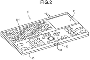
- FIG. 2 is a perspective view illustrating the configuration of the input device according to the first embodiment.
- the input device 5 includes a main body unit 50 as a housing, a display unit 51, a track ball 52, and a press button 53.
- the display unit 51 is provided on one surface of the main body unit 50 and capable of displaying various types of information.
- the track ball 52 has a spherical shape and is provided in a state where the track ball 52 is partially exposed from the surface of the main body unit 50.
- the press button 53 is pressed when the track ball 52 is extracted from the main body unit 50.
- a plurality of keys 501 arranged on the input device 5 is exposed from the main body unit 50 and can be depressed.
- the input device 5 is electrically connected to the ultrasound observation apparatus 3 via a cable and inputs information on the rotation amount and rotation direction of the track ball and a command signal by depressing the key 501, to the input unit 33.
- an optical sensor detects the rotation amount and the rotation direction of the track ball 52, generates information indicating a detection result, and outputs the information to the ultrasound observation apparatus 3.
- the ultrasound observation apparatus 3 performs signal processing corresponding to the input rotation amount and rotation direction, on the basis of the received information.
- FIG. 3 is a perspective view illustrating a configuration of main parts of the input device according to the first embodiment, illustrating the track ball 52 and an extraction mechanism for extracting the track ball 52.
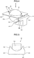
- FIG. 4 is a perspective view illustrating a configuration of the main parts of the input device according to the first embodiment, in which the press button 53 is removed from the configuration illustrated in FIG. 3 .
- FIG. 5 is a plan view illustrating a configuration of the main parts of the input device according to the first embodiment, illustrating the configuration of a moving member 54.
- FIG. 6 is a plan view illustrating a configuration of the main parts of the input device according to the first embodiment, illustrating the configuration in the direction of arrow A illustrated in FIG. 4 .
- An extraction mechanism 100 for extracting the track ball 52 from the main body unit 50 is provided inside the main body unit 50.
- the extraction mechanism 100 includes the above-described press button 53, the moving member 54, and an opening forming member 55.
- the moving member 54 is connected to the press button 53 and movable in a direction of approaching the track ball 52 or in a direction of receding from the track ball 52.
- the opening forming member 55 is capable of forming an opening having a diameter that locks the track ball 52 or an opening having a diameter that allows passing of the track ball 52.
- the size of the diameter of the opening forming member 55 changes in conjunction with the movement of the moving member 54.
- the moving member 54 includes a base 541, two arms 542, a side surface portion 543, and an inclined portion 544.
- the base 541 receives a load from the press button 53 and is movable in a direction of moving toward the track ball 52 in accordance with the received load.
- the two arms 542 extend from the base 541.
- the side surface portion 543 constitutes a portion of a side surface of the base 541 and is continuous with the arm 542.
- the inclined portion 544 is provided on a side that is opposite to a side to which load is applied from the press button 53 of the base 541 and that faces the track ball 52.
- the inclined portion 544 has an inclined surface inclined in a moving direction of the base 541.
- the distance between the outer surfaces of the opposing arms 542 is smaller than the distance between the outer surfaces of the opposing side surface portions 543.
- the term "outer surface” as used herein refers to the surface opposite to the mutually opposing sides.
- the inclined surface of the inclined portion 544 also includes a step-like surface whose height changes stepwise.
- the opening forming member 55 includes a first opening forming member 551 and a second opening forming member 552, capable of respectively forming a large diameter opening or a small diameter opening with respect to the track ball 52 diameter.
- Each of the first opening forming member 551 and the second opening forming member 552 is pivotably supported on a rotation shaft 553 fixed inside the main body unit 50.
- each of the first opening forming member 551 and the second opening forming member 552 is in contact with, for example, each of end portions of torsion springs (not illustrated) provided on the rotation shaft 553, and thus, is in a state where a load is applied in a direction of allowing the end on the rotation shaft 553 side and the end on the side opposite to the rotation shaft 553 side to move toward each other.
- each of the first opening forming member 551 and the second opening forming member 552 includes an abutment pin 554 that respectively abuts each of the arms 542 and the side surface portion 543 continuous with the each of the arms 542.
- the arm 542, the side surface portion 543 and the abutment pin 554 constitute a diameter expanding unit.
- the first opening forming member 551 is formed on the side opposing the second opening forming member 552 and includes a first opening forming portion 551a in an arc shape.
- the second opening forming member 552 is formed on the side opposing the first opening forming member 551 and includes a second opening forming portion 552a in an arc shape.
- An opening S1 (refer to FIG. 6 ) is formed by the first opening forming portion 551a and the second opening forming portion 552a. In a case where the opening S1 forms a circle, the diameter of this circle is smaller than the diameter of the track ball 52.
- the opening S1 has an elliptical shape or a shape other than a circle, the minimum length among the lengths of the openings passing through the center is smaller than the diameter of the track ball 52.
- a damper mechanism is provided between the press button 53 and the moving member 54.
- a coil spring 53a is provided between the press button 53 and the moving member 54, whereby the load at the time when the press button 53 is pressed is reduced to suppress the moving speed of the moving member 54, while the press button 53 is returned to a normal position in a case where the pressing of the press button 53 is released.
- the normal position is the position of the press button 53 before being pressed. It is not necessary to provide the damper mechanism.
- FIG. 7 is a perspective view illustrating a configuration of the main parts of the input device according to the first embodiment, illustrating a case where the press button 53 is pressed.
- FIG. 8 is a plan view illustrating a configuration of the main parts of the input device according to the first embodiment, illustrating a configuration in the direction of arrow B illustrated in FIG. 7 .
- the abutment pin 554 moves along the outer surface of the arm 542 in conjunction with the movement of the moving member 54.
- the abutment pin 554 moves from the arm 542 to the side surface portion 543 along the movement of the moving member 54 as illustrated in FIGS. 7 and 8 , the first opening forming member 551 and the second opening forming member 552 rotate around the rotation shaft 553 in conjunction with the movement.
- the diameter of an opening S2 formed by the first opening forming portion 551a and the second opening forming portion 552a becomes larger than the diameter of the opening S1. It is preferable that the diameter of the expanded opening S2 is larger than the diameter of the track ball 52.
- the diameter of the opening S2 may be not larger than the diameter of the track ball 52 provided that a coating, or the like, that can suppress damage on the track ball 52 is applied to portions that come in contact with the track ball 52, on each of the first opening forming portion 551a and the second opening forming portion 552a.
- the track ball 52 rides on the inclined surface of the inclined portion 544 in conjunction with the movement of the moving member 54.
- the track ball 52 moves upward with respect to the moving member 54, that is, the amount of protrusion of the track ball 52 from the surface of the main body unit 50 increases, in accordance with the entering amount of the inclined portion 544.
- the time of changing from the opening S1 to the opening S2 and at the time of lifting the track ball 52 by the inclined portion 544 it is preferable not to contact the track ball 52 with the first opening forming portion 551a and the second opening forming portion 552a.
- the time of changing from the opening S1 to the opening S2 and the time of lifting the track ball 52 are adjustable by the arrangement of the arm 542, the side surface portion 543, and the inclined surface of the inclined portion 544 and an angle of the inclined surface of the inclined portion 544.
- FIG. 9 is a diagram illustrating extraction of the track ball in the input device according to the first embodiment. Specifically, (a) of FIG. 9 illustrates a state before the press button 53 is pressed, and (b) of FIG. 9 illustrates a state after the press button 53 is pressed. As illustrated in FIG.
- the diameter of the opening S2 increases so as not to contact with the track ball 52, which leads to an increase in the amount of protrusion of the track ball 52 from the surface of the main body unit 50.
- the amount of protrusion of the track ball 52 from the main body unit 50 can be easily adjusted by changing the angle of the inclined surface of the inclined portion 544.
- the press button 53 is depressed to expand the opening formed by the first opening forming portion 551a and the second opening forming portion 552a (to form the opening S2), and then, the track ball 52 is dropped into the main body unit 50 from the opening S2. Thereafter, when the pressed state of the press button 53 is released, the inclined portion 544 retreats from the track ball 52 by the self-weight of the track ball 52 or a biasing member such as a coil spring (not illustrated), while the diameter of the opening formed by the first opening forming portion 551a and the second opening forming portion 552a returns to the diameter of the opening S1, and the moving member 54 returns to the normal position.
- a biasing member such as a coil spring
- a latch mechanism may be provided such that the position of the moving member 54 is held by the latch mechanism. For example, when the pressing amount of the press button 53 (moving amount of the moving member 54) reaches a predetermined amount, the latch mechanism is turned on (holding state), and when the press button 53 is further pressed, the latching mechanism is turned off (holding release state). At this time, the object to be held by the latch mechanism may be the moving member 54 or the press button 53.
- the opening S1 formed by the first opening forming portion 551a and the second opening forming portion 552a is smaller than the track ball 52 in diameter when the press button 53 is not pressed, making it possible to prevent the track ball 52 from falling from the main body unit 50.
- the diameter of the opening formed by the first opening forming portion 551a and the second opening forming portion 552a is changed to the opening S2 so as not to contact with the track ball 52, and the track ball 52 rides on the inclined portion 544, which leads to the increased amount of protrusion of the track ball 52 from the surface of the main body unit 50.
- FIG. 10 is a perspective view illustrating a configuration of main parts of an input device according to the first modification of the first embodiment of the present invention, illustrating the track ball 52 and an extraction mechanism for extracting the track ball 52.
- the same reference signs are used to designate the same elements as those in the first embodiment.
- the press button 53 is provided in the first embodiment, the moving member 54 is configured to be moved under the control of a motor M (driving source) without providing the press button 53 in the first modification.
- An extraction mechanism 100a illustrated in FIG. 10 includes the above-described moving member 54, the opening forming member 55, and a drive unit 56 configured to transmit a driving force generated by the motor M to move the moving member 54 in a direction of approaching the track ball 52 or in a direction of receding from the track ball 52.
- the drive unit 56 includes a supporting-moving unit 561, a first gear 562, and a second gear 563.
- the supporting-moving unit 561 supports the moving member 54 and is movable in a direction of approaching the track ball 52 or in a direction of receding from the track ball 52.
- the first gear 562 is connected to the motor M that generates motive power regarding the movement of the supporting-moving unit 561 and is rotatable by rotation of the motor M.
- the second gear 563 is provided between the supporting-moving unit 561 and the first gear 562.
- the supporting-moving unit 561 includes a supporting section 561a and a first meshing section 561b.
- the supporting section 561a supports the moving member 54.
- the first meshing section 561b is continuous with the supporting section 561a and has a saw-tooth pattern extending in a direction of moving the supporting section 561 to mesh with the second gear 563.
- the second gear 563 coaxially includes a second meshing section 563a and a third meshing section 563b.
- the second meshing section 563a is configured to mesh with the first meshing section 561b.
- the third meshing section 563b is configured to mesh with the first gear 562.
- the rotation of the motor M causes the second gear 563 to rotate, thereby causing the third meshing section 563b to rotate in conjunction with the rotation of the second gear 563.
- the rotation of the third meshing section 563b causes the second meshing section 563a to rotate, thereby causing the supporting section 561 to move via the first meshing section 561b.
- the movement of the supporting section 561 enables the moving member 54 to move in a direction of approaching the track ball 52 or in a direction of receding from the track ball 52.
- the first modification it is possible to obtain the same effects as in the first embodiment as well as to easily extract the track ball 52 merely by controlling the motor M.
- the track ball 52 is extracted while the user keeps pressing the press button 53.
- the first modification enables controlling the rotation of the motor M on the basis of the depression of a key 501, or the like. This configuration enables, for example, the track ball 52 to move forward and backward from the main body unit 50 by merely depressing the key 501 once, making it possible to extract or attach the track ball 52 more easily.
- the first modification may be configured such that the motor M is driven on the basis of a control signal from the ultrasound observation apparatus 3.
- the moving member 54 may be moved by driving the motor M under the control of the input device 5 or the ultrasound observation apparatus 3 when a predetermined condition is satisfied. For example, if the number of times of startup of the apparatus is adopted as the predetermined condition and when a predetermined number of times of power supply startup is reached, the motor M is driven to automatically move the track ball 52 to an extraction position at the time of power supply startup and to urge the user to clean the track ball 52.
- the ultrasound observation apparatus 3 counts the number of times of power supply startup (apparatus startup by power supply from the ultrasound observation apparatus 3), and then, in a case where the count has reached the predetermined number, the motor M is driven to move the track ball 52 to the extraction position.
- the motor M may be controlled on the input device 5 side.
- While the driving force of the motor M is transmitted by meshing in the first modification, it is also possible to use a known power transmission means such as transmission of rotational power by a frictional force or transmission of rotational power using a belt, or the like.
- FIGS. 11 and 12 are perspective views illustrating a configuration of main parts of an input device according to the second modification of the first embodiment of the present invention, illustrating the track ball 52 and an extraction mechanism 100b for extracting the track ball 52.
- the same reference signs are used to designate the same elements as those in the first embodiment.
- the configuration of the second modification includes a cleaning unit 545 that cleans a detection sensor 57 configured to detect the rotation amount and the rotation direction of the track ball 52.
- the track ball 52 has a patterned or irregular surface, and information (rotation amount and rotation direction) related to the rotation of the track ball 52 is detectable by the optical detection sensor 57.
- the detection sensor 57 is fixed to the main body unit 50, emits light to a predetermined position of the track ball, receives reflected light, and outputs the received light to a calculation unit, or the like, in the main body unit 50 as detection information (track ball 52 movement information).
- the detection sensor 57 may be a sensor for receiving light emitted from the outside and reflected from the track ball 52, that is, a sensor for receiving light only.
- the moving member 54a includes the cleaning unit 545 on a side surface of the inclined portion 544, orthogonal to the inclined surface and facing the detection sensor 57.
- the cleaning unit 545 is in sliding contact with a light emitting/receiving surface of the detection sensor 57, and removes extraneous matter from the light emitting/receiving surface.
- the cleaning unit 545 is provided so as to be in sliding contact with the light emitting/receiving surface of the detection sensor 57 during the movement of the moving member 54a toward the track ball 52 side at the time of removal of the track ball 52 (refer to FIG. 12 ).
- the cleaning unit 545 has a surface formed of cloth or elastically deformable material with concavo-convex patterns, for example, the surface being configured to be in contact with the light emitting/receiving surface.
- the cleaning unit 545 may be formed by a brush-like member.
- the cleaning unit 545 is in sliding contact with the light emitting/receiving surface of the detection sensor 57 to perform cleaning while the moving member 54 is moving toward the track ball 52 at the time of extracting the track ball 52. Accordingly, it is possible to perform cleaning of the detection sensor 57 simultaneously with the extraction of the track ball 52 using the moving member 54.
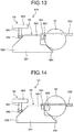
- FIG. 13 is a side view illustrating a configuration of main parts of an input device according to the second embodiment, illustrating the track ball 52 and an extraction mechanism for extracting the track ball 52.
- FIG. 13 is a diagram illustrating a state when the press button is not pressed. The same reference signs are used to designate the same elements as those in the first embodiment.
- the press button is pressed in the direction substantially orthogonal to the extraction direction of the track ball 52.
- the press button is pressed in the direction substantially parallel to the extraction direction of the track ball 52.
- the input device includes the main body unit 50, the display unit 51, the track ball 52, and a press button 58 that is pressed when the track ball 52 is extracted from the main body unit 50. Moreover, an extraction mechanism 101 for extracting the track ball 52 from the main body unit 50 is provided inside the main body unit 50.
- the extraction mechanism 101 for extracting the track ball 52 from the main body unit 50 includes the above-described press button 58, a moving member 59, and the opening forming member 55.
- the moving member 59 comes in contact with the press button 58, and moves in a direction of moving toward the track ball 52 in accordance with the load by the pressing when the press button 58 is pressed.
- the opening forming member 55 is capable of forming an opening having a diameter that locks the track ball 52, or an opening having a diameter that allows passing of the track ball 52. The size of the diameter of the opening of the opening forming member 55 changes in conjunction with the movement of the moving member 59.
- the press button 58 includes a press section 581, a roller 582, and a holding section 583.
- the press section 581 is pressed by the user.
- the roller 582 comes in contact with the moving member 59.
- the holding section 583 extends in a direction substantially parallel to the direction to which a load by pressing is applied from the press section 581, and rotatably holds, at its distal end, the roller 582.
- the moving member 59 includes a base 591, two arms 592, a side surface portion 593, an inclined portion 594, and an abutment portion 595.
- the base 591 receives a load from the press button 58 (roller 582) and is movable in a direction of moving toward the track ball 52 in accordance with the received load.
- the two arms 592 extend from the base 591 (although solely one of the two is illustrated in FIG. 13 ).
- the side surface portion 593 constitutes a portion of a side surface of the base 591 and is continuous with the arm 592.
- the inclined portion 594 is provided on a side that is opposite to a side to which load is applied from the press button 58 of the base 591 and that faces the track ball 52.
- the inclined portion 594 has an inclined surface inclined in a moving direction of the base 591.
- the abutment portion 595 is continuous with the base 591 and includes an inclined surface that abuts the roller 582.
- the distance between the outer surfaces of the opposing arms 592 is smaller than the distance between the outer surfaces of the opposing side surface portions 593.
- FIG. 14 is a side view illustrating a configuration of the main parts of the input device according to the second embodiment, illustrating a case where the press button 58 is pressed.
- the roller 582 moves on the inclined surface of the abutment portion 595.
- a force in a direction orthogonal to the direction of the load that is, a force in the direction orthogonal to the extraction direction of the track ball 52 is applied to the moving member 59, due to the load applied to the press section 581, thereby moving the moving member 59 toward the track ball 52 side.
- the abutment pin 554 moves along the outer surface of the arm 592 in conjunction with the movement of the moving member 59. It is possible to adjust the moving amount of the moving member 59 with respect to the pressing amount of the press button 58 by adjusting the angle of the inclined surface with respect to the moving direction of the moving member 59, on the abutment portion 595.
- the first opening forming member 551 and the second opening forming member 552 rotate around the rotation shaft 553 in conjunction with the movement.
- the opening formed by the first opening forming portion 551a and the second opening forming portion 552a is changed from the opening S1 to the opening S2, as described above.
- the track ball 52 rides on the inclined surface of the inclined portion 594 in conjunction with the movement of the moving member 59.
- the track ball 52 moves upward with respect to the moving member 59, that is, the amount of protrusion of the track ball 52 from the surface of the main body unit 50 increases, in accordance with the entering amount of the inclined portion 594.
- the diameter of the opening S2 increases so as not to contact with the track ball 52, which leads to an increase in the amount of protrusion of the track ball 52 from the surface of the main body unit 50. This makes it possible to easily extract the track ball 52 by merely depressing the press button 58.
- the press button 58 is depressed, and thereafter, the opening formed by the first opening forming portion 551a and the second opening forming portion 552a is expanded (to form the opening S2), and the track ball 52 is dropped into the main body unit 50 from the opening S2. Thereafter, when the pressed state of the press button 58 is released, the inclined portion 594 retreats from the track ball 52 by the self-weight of the track ball 52 or a biasing member such as a coil spring (not illustrated), while the diameter of the opening formed by the first opening forming portion 551a and the second opening forming portion 552a returns to the diameter of the opening S1, and the moving member 59 returns to the normal position.
- a biasing member such as a coil spring
- the opening S1 formed by the first opening forming portion 551a and the second opening forming portion 552a is smaller than the track ball 52 in diameter when the press button 58 is not pressed, making it possible to prevent the track ball 52 from falling from the main body unit 50.
- the diameter of the opening formed by the first opening forming portion 551a and the second opening forming portion 552a is changed to the opening S2 so as not to contact with the track ball 52, and the track ball 52 rides on the inclined portion 594, which leads to the increased amount of protrusion of the track ball 52 from the surface of the main body unit 50.
- the opening forming member 55 changes the diameter of the opening in conjunction with the movement of the moving member.
- the opening forming member 55 may be formed of elastically deformable material, and when the track ball 52 protrudes from the main body unit 50, the opening forming member 55 may be elastically deformed by contact with the track ball 52 so as to enable the track ball 52 to be extracted.
- a slit may be formed in the elastically deformable opening forming member 55.
- the above-described first and second embodiments describe exemplary cases of the ultrasound endoscope capable of transmitting and receiving ultrasound and capable of capturing inner portions of the subject with the imaging optical system.
- the configuration is not limited to this but may also include an endoscope equipped with a ultrasound probe and an imaging optical system, and a capsule endoscope.
- the medical input device according to the first and second embodiments can be used for operating these endoscopes and probes and for inputting command signals at processing of information obtained by the endoscope and the probe.
- the ultrasound miniature probe that has a small diameter and has no optical system, as the ultrasound probe.
- the ultrasound miniature probe is inserted into biliary tract, bile duct, pancreatic duct, trachea, bronchus, urethra, and ureter, and is applicable to the examination of the surrounding organs (pancreas, lung, prostate gland, bladder, and lymph nodes, or the like).
- an external ultrasound probe that emits ultrasound from the surface of the subject.
- the external ultrasound probe is typically used to examine abdominal organs (liver, gall bladder, and bladder), breast (mammary gland, in particular), and the thyroid.
- the medical input device according to the present invention is useful for easily attaching and detaching the track ball to and from the housing.
Landscapes
- Engineering & Computer Science (AREA)
- General Engineering & Computer Science (AREA)
- Theoretical Computer Science (AREA)
- Physics & Mathematics (AREA)
- Health & Medical Sciences (AREA)
- Life Sciences & Earth Sciences (AREA)
- Human Computer Interaction (AREA)
- General Physics & Mathematics (AREA)
- Pathology (AREA)
- Molecular Biology (AREA)
- Biophysics (AREA)
- Radiology & Medical Imaging (AREA)
- Biomedical Technology (AREA)
- Heart & Thoracic Surgery (AREA)
- Medical Informatics (AREA)
- Nuclear Medicine, Radiotherapy & Molecular Imaging (AREA)
- Surgery (AREA)
- Animal Behavior & Ethology (AREA)
- General Health & Medical Sciences (AREA)
- Public Health (AREA)
- Veterinary Medicine (AREA)
- Ultra Sonic Daignosis Equipment (AREA)
- Position Input By Displaying (AREA)
Abstract
Description
- The present invention relates to a medical input device.
- In order to examine or observe characteristics of body tissues or material as an observation target, an image generated by imaging or an image generated by ultrasound may sometimes be applied. The diagnosis of the body tissues inside the body uses an ultrasound endoscope including an ultrasound transducer and an image sensor at a distal end of an insertion unit.
- In the diagnosis by the ultrasound endoscope, for example, an image generated by an image processing apparatus on the basis of the ultrasound echo or an imaging signal obtained by the ultrasound endoscope is displayed on a monitor. Settings of an examination mode and observation conditions at the time of diagnosis, or the like, are performed on the basis of a command signal input via an input device.
- A technique employing a spherical track ball is known as an exemplary input device, (refer to, for example, Patent Literature 1).
Patent Literature 1 discloses a track ball device in which a track ball is held by first and second casings that are removable from each other and constitute a housing. This technique enables an input of a command signal corresponding to the rotation amount and the rotation direction of the track ball, and is known as an input unit having excellent operability. - Patent Literature 1:
JP 2011-210113 A - In the track ball device disclosed in
Patent Literature 1, in a case where the track ball is detached from the housing for cleaning or the like, cleaning of the track ball, or the like is performed by extracting the track ball after the second casing is removed from the first casing. In this manner, the case ofPatent Literature 1 needs detachment of the second casing from the first casing or attachment every time the track ball is cleaned, which takes time and labor. Therefore, there has been a demand for a technology capable of easily attaching and detaching the track ball to and from the housing. - The present invention has been made in view of the foregoing, and an object of the invention is to provide a medical input device capable of easily attaching and detaching a track ball to and from the housing.
- In order to solve the above described problem and achieve the object, a medical input device according to the invention is a medical input device for receiving an input of a command signal. The medical input device includes: a main body unit that is a housing; a track ball partially protruding from the main body unit and provided rotatably; a moving member having an inclined surface on which the track ball is configured to ride, the moving member being movable in a direction of approaching the track ball or in a direction of receding from the track ball; and an opening forming member configured to form at least an opening which has a diameter smaller than that of the track ball and through which the track ball partially protrudes.
- The medical input device according to the invention further includes a diameter expanding unit configured to expand the opening of the opening forming member to the diameter larger than that of the track ball in conjunction with movement of the moving member in the direction of approaching the track ball.
- The medical input device according to the invention further includes: a driving source configured to generate a driving force for moving the moving member; and a drive unit configured to transmit the driving force generated by the driving source to move the moving member in the direction of approaching the track ball or in the direction of receding from the track ball.
- In the medical input device according to the invention, when a predetermined condition related to startup of the medical input device is satisfied, the moving member is moved by driving the driving source.
- The medical input device according to the invention further includes: a detection sensor configured to detect light from a surface of the track ball and output a detection result as information related to rotation of the track ball; and a cleaning unit provided on a side surface of the moving member facing the detection sensor and configured to be in sliding contact with a light receiving surface of the detection sensor to remove extraneous matter from the light receiving surface of the detection sensor during movement of the moving member in the direction of approaching the track ball.
- According to the present invention, it is possible to easily attach and detach the track ball to and from the housing.
-
-
FIG. 1 is a block diagram illustrating a configuration of an ultrasound diagnosis system equipped with an ultrasound observation apparatus according to a first embodiment of the present invention. -
FIG. 2 is a perspective view illustrating a configuration of an input device according to the first embodiment of the present invention. -
FIG. 3 is a perspective view illustrating a configuration of main parts of the input device according to the first embodiment of the present invention. -
FIG. 4 is a perspective view illustrating a configuration of the main parts of the input device according to the first embodiment of the present invention. -
FIG. 5 is a plan view illustrating a configuration of the main parts of the input device according to the first embodiment of the present invention. -
FIG. 6 is a plan view illustrating a configuration of the main parts of the input device according to the first embodiment of the present invention. -
FIG. 7 is a perspective view illustrating a configuration of the main parts of the input device according to the first embodiment of the present invention. -
FIG. 8 is a plan view illustrating a configuration of the main parts of the input device according to the first embodiment of the present invention. -
FIG. 9 is a view illustrating extraction of a track ball in the input device according to the first embodiment of the present invention. -
FIG. 10 is a perspective view illustrating a configuration of main parts of an input device according to a first modification of the first embodiment of the present invention. -
FIG. 11 is a perspective view illustrating a configuration of main parts of an input device according to a second modification of the first embodiment of the present invention. -
FIG. 12 is a perspective view illustrating a configuration of the main parts of the input device according to the second modification of the first embodiment of the present invention. -
FIG. 13 is a side view illustrating a configuration of main parts of an input device according to a second embodiment of the present invention. -
FIG. 14 is a side view illustrating the configuration of the main parts of the input device according to the second embodiment of the present invention. - Hereinafter, modes for carrying out the present invention (hereinafter, referred to as embodiment(s)) will be described with reference to the attached drawings. The following description will exemplify an ultrasound diagnosis system including a medical input device that generates an ultrasound image based on an ultrasound echo. The present invention, however, is not limited to these embodiments. The same reference signs are used to designate the same elements throughout the drawings.
-
FIG. 1 is a block diagram illustrating a functional configuration of an ultrasound diagnosis system equipped with an ultrasound observation apparatus according to a first embodiment of the present invention. Anultrasound diagnosis system 1 illustrated inFIG. 1 includes anultrasound endoscope 2, anultrasound observation apparatus 3, a display device 4, and an input device (medical input device) 5. Theultrasound endoscope 2 transmits ultrasound to a subject as an observation target and receives ultrasound reflected on the subject. Theultrasound observation apparatus 3 generates an ultrasound image on the basis of the ultrasound signal obtained by theultrasound observation apparatus 3. The display device 4 displays the ultrasound image generated by theultrasound observation apparatus 3. Theinput device 5 inputs a command signal for examination mode setting, observation condition setting, or the like. - The
ultrasound endoscope 2 includes, on its distal end portion, anultrasound transducer 21. Theultrasound transducer 21 converts an electrical pulse signal received from theultrasound observation apparatus 3 into an ultrasound pulse (acoustic pulse) and emits it to the subject. Theultrasound transducer 21 also converts an ultrasound echo reflected on the subject into an electrical echo signal (ultrasound signal) expressed by a voltage change and outputs the signal. Theultrasound transducer 21 is realized by a radial transducer. Theultrasound endoscope 2 may cause theultrasound transducer 21 to perform mechanical scan, or may provide, as theultrasound transducer 21, a plurality of elements in an array, and may cause the ultrasound transducer to perform electronic scan by electronically switching elements related to transmission/reception or imposing delay onto transmission/reception of each of elements. - The
ultrasound endoscope 2 typically includes an imaging unit having an imaging optical system and an image sensor. Theultrasound endoscope 2 can be inserted into gastrointestinal tracts (esophagus, stomach, duodenum, and large intestine) or respiratory organs (trachea, bronchus) of the subject and can capture gastrointestinal tract, respiratory organs, and their surrounding organs (pancreas, gall bladder, bile duct, biliary tract, lymph nodes, mediastinal organs, blood vessels, or the like). Theultrasound endoscope 2 includes a light guide that guides illumination light emitted to the subject at the time of capturing. The light guide is configured such that a distal end portion thereof reaches a distal end of an insertion unit of theultrasound endoscope 2 into the subject, while a proximal end thereof is connected to a light source device that generates illumination light. - The
ultrasound observation apparatus 3 includes a transmitting and receiving unit 31, an image processing unit 32, an input unit 33, control unit 34, and astorage unit 35. - The transmitting and receiving unit 31 performs transmission and reception of electrical signals between the imaging unit and the
ultrasound transducer 21. The transmitting and receiving unit 31 is electrically connected with the imaging unit, transmits imaging information such as an imaging timing to the imaging unit and receives an imaging signal generated by the imaging unit. Moreover, the transmitting and receiving unit 31 is electrically connected with theultrasound transducer 21, transmits an electrical pulse signal to theultrasound transducer 21, and receives an echo signal as an electrical reception signal from theultrasound transducer 21. Specifically, the transmitting and receiving unit 31 generates an electrical pulse signal on the basis of a preset waveform and transmission timing and transmits the generated pulse signal to theultrasound transducer 21. - The transmitting and receiving unit 31 performs sensitivity time control (STC) correction that amplifies an echo signal having a larger receiving depth by using a higher amplification factor. The transmitting and receiving unit 31 performs processing such as filtering on the amplified echo signal, and thereafter, generates digital high-frequency signal, namely, a radio frequency (RF) signal of time domain by performing A/D conversion on the signal, and outputs the generated signal.
- The image processing unit 32 generates endoscopic image data based on the imaging signal and generates image data corresponding to the electrical echo signal.
- The input unit 33 receives the command signal input by the
input device 5 and receives an input of various types of information corresponding to the received command signal. Examples of the various types of information include examination mode setting and observation condition setting (for example, switching of gain and display range, and scroll instruction information (sliding direction and sliding amount of B mode image)). - The control unit 34 controls the entire
ultrasound diagnosis system 1. The control unit 34 includes a CPU having calculation/control functions, various calculation circuits, or the like. The control unit 34 reads, from thestorage unit 35, information stored in thestorage unit 35, and executes various types of calculation processing related to the method for operating theultrasound observation apparatus 3, thereby integrally controlling theultrasound observation apparatus 3. The control unit 34 and the image processing unit 32 may share the same CPU. - The
storage unit 35 stores various programs for operating theultrasound diagnosis system 1, data including various parameters needed for operation of theultrasound diagnosis system 1, or the like. Thestorage unit 35 stores, for example, an initial position (sound ray number) of a writing position (ultrasound transmission start position) of the ultrasound image. - The
storage unit 35 also stores various programs including an operation program for executing a method for operating theultrasound diagnosis system 1. The operation programs can be recorded in a computer-readable recording medium such as a hard disk, flash memory, CD-ROM, DVD-ROM, flexible disk, or the like, and can be distributed broadly. It is also possible to obtain the above-described various programs by downloading them via a communication network. Herein, the communication network refers to one implemented by, for example, a known public network, a local area network (LAN), a wide area network (WAN), regardless of wired or wireless. - The above-configured
storage unit 35 is formed with a read only memory (ROM) in which various programs are pre-installed, a random access memory (RAM) that stores calculation parameters and data for each of processing, or the like. - Next, the
input device 5 will be described with reference toFIGS. 2 to 9 .FIG. 2 is a perspective view illustrating the configuration of the input device according to the first embodiment. - As illustrated in
FIG. 2 , theinput device 5 includes amain body unit 50 as a housing, adisplay unit 51, atrack ball 52, and apress button 53. Thedisplay unit 51 is provided on one surface of themain body unit 50 and capable of displaying various types of information. Thetrack ball 52 has a spherical shape and is provided in a state where thetrack ball 52 is partially exposed from the surface of themain body unit 50. Thepress button 53 is pressed when thetrack ball 52 is extracted from themain body unit 50. Moreover, a plurality ofkeys 501 arranged on theinput device 5 is exposed from themain body unit 50 and can be depressed. Theinput device 5 is electrically connected to theultrasound observation apparatus 3 via a cable and inputs information on the rotation amount and rotation direction of the track ball and a command signal by depressing the key 501, to the input unit 33. - On the
input device 5, when thetrack ball 52 is rotated by operation of an operator, for example, an optical sensor (not illustrated) detects the rotation amount and the rotation direction of thetrack ball 52, generates information indicating a detection result, and outputs the information to theultrasound observation apparatus 3. Theultrasound observation apparatus 3 performs signal processing corresponding to the input rotation amount and rotation direction, on the basis of the received information. - Subsequently, a configuration and a method for extracting the
track ball 52 from themain body unit 50 will be described with reference toFIGS. 3 to 9 .FIG. 3 is a perspective view illustrating a configuration of main parts of the input device according to the first embodiment, illustrating thetrack ball 52 and an extraction mechanism for extracting thetrack ball 52.FIG. 4 is a perspective view illustrating a configuration of the main parts of the input device according to the first embodiment, in which thepress button 53 is removed from the configuration illustrated inFIG. 3 .FIG. 5 is a plan view illustrating a configuration of the main parts of the input device according to the first embodiment, illustrating the configuration of a movingmember 54.FIG. 6 is a plan view illustrating a configuration of the main parts of the input device according to the first embodiment, illustrating the configuration in the direction of arrow A illustrated inFIG. 4 . - An
extraction mechanism 100 for extracting thetrack ball 52 from themain body unit 50 is provided inside themain body unit 50. As illustrated inFIG. 3 , theextraction mechanism 100 includes the above-describedpress button 53, the movingmember 54, and anopening forming member 55. The movingmember 54 is connected to thepress button 53 and movable in a direction of approaching thetrack ball 52 or in a direction of receding from thetrack ball 52. When thepress button 53 is pressed, the movingmember 54 moves toward thetrack ball 52 in accordance with the load by the pressing. Theopening forming member 55 is capable of forming an opening having a diameter that locks thetrack ball 52 or an opening having a diameter that allows passing of thetrack ball 52. The size of the diameter of theopening forming member 55 changes in conjunction with the movement of the movingmember 54. - The moving
member 54 includes abase 541, twoarms 542, aside surface portion 543, and aninclined portion 544. Thebase 541 receives a load from thepress button 53 and is movable in a direction of moving toward thetrack ball 52 in accordance with the received load. The twoarms 542 extend from thebase 541. Theside surface portion 543 constitutes a portion of a side surface of thebase 541 and is continuous with thearm 542. Theinclined portion 544 is provided on a side that is opposite to a side to which load is applied from thepress button 53 of thebase 541 and that faces thetrack ball 52. Theinclined portion 544 has an inclined surface inclined in a moving direction of thebase 541. The distance between the outer surfaces of the opposingarms 542 is smaller than the distance between the outer surfaces of the opposingside surface portions 543. The term "outer surface" as used herein refers to the surface opposite to the mutually opposing sides. Moreover, the inclined surface of theinclined portion 544 also includes a step-like surface whose height changes stepwise. - The
opening forming member 55 includes a firstopening forming member 551 and a secondopening forming member 552, capable of respectively forming a large diameter opening or a small diameter opening with respect to thetrack ball 52 diameter. Each of the firstopening forming member 551 and the secondopening forming member 552 is pivotably supported on arotation shaft 553 fixed inside themain body unit 50. Moreover, each of the firstopening forming member 551 and the secondopening forming member 552 is in contact with, for example, each of end portions of torsion springs (not illustrated) provided on therotation shaft 553, and thus, is in a state where a load is applied in a direction of allowing the end on therotation shaft 553 side and the end on the side opposite to therotation shaft 553 side to move toward each other. - Moreover, each of the first
opening forming member 551 and the secondopening forming member 552 includes anabutment pin 554 that respectively abuts each of thearms 542 and theside surface portion 543 continuous with the each of thearms 542. In the first embodiment, thearm 542, theside surface portion 543 and theabutment pin 554 constitute a diameter expanding unit. - The first
opening forming member 551 is formed on the side opposing the secondopening forming member 552 and includes a firstopening forming portion 551a in an arc shape. The secondopening forming member 552 is formed on the side opposing the firstopening forming member 551 and includes a secondopening forming portion 552a in an arc shape. An opening S1 (refer toFIG. 6 ) is formed by the firstopening forming portion 551a and the secondopening forming portion 552a. In a case where the opening S1 forms a circle, the diameter of this circle is smaller than the diameter of thetrack ball 52. When the opening S1 has an elliptical shape or a shape other than a circle, the minimum length among the lengths of the openings passing through the center is smaller than the diameter of thetrack ball 52. - Moreover, a damper mechanism is provided between the
press button 53 and the movingmember 54. Specifically, acoil spring 53a is provided between thepress button 53 and the movingmember 54, whereby the load at the time when thepress button 53 is pressed is reduced to suppress the moving speed of the movingmember 54, while thepress button 53 is returned to a normal position in a case where the pressing of thepress button 53 is released. Here, the normal position is the position of thepress button 53 before being pressed. It is not necessary to provide the damper mechanism. -
FIG. 7 is a perspective view illustrating a configuration of the main parts of the input device according to the first embodiment, illustrating a case where thepress button 53 is pressed.FIG. 8 is a plan view illustrating a configuration of the main parts of the input device according to the first embodiment, illustrating a configuration in the direction of arrow B illustrated inFIG. 7 . - When the
press button 53 is pressed and the movingmember 54 moves toward thetrack ball 52, theabutment pin 554 moves along the outer surface of thearm 542 in conjunction with the movement of the movingmember 54. When theabutment pin 554 moves from thearm 542 to theside surface portion 543 along the movement of the movingmember 54 as illustrated inFIGS. 7 and8 , the firstopening forming member 551 and the secondopening forming member 552 rotate around therotation shaft 553 in conjunction with the movement. - When the first
opening forming member 551 and the secondopening forming member 552 rotate around therotation shaft 553, the end portions of the firstopening forming member 551 and the secondopening forming member 552, which are on the opposite side of therotation shaft 553, move away from each other. Accordingly, the diameter of an opening S2 formed by the firstopening forming portion 551a and the secondopening forming portion 552a, for example, the diameter of the circle inscribed in the opening S2, becomes larger than the diameter of the opening S1. It is preferable that the diameter of the expanded opening S2 is larger than the diameter of thetrack ball 52. The diameter of the opening S2 may be not larger than the diameter of thetrack ball 52 provided that a coating, or the like, that can suppress damage on thetrack ball 52 is applied to portions that come in contact with thetrack ball 52, on each of the firstopening forming portion 551a and the secondopening forming portion 552a. - When the
press button 53 is pressed and the movingmember 54 moves toward thetrack ball 52, thetrack ball 52 rides on the inclined surface of theinclined portion 544 in conjunction with the movement of the movingmember 54. Thetrack ball 52 moves upward with respect to the movingmember 54, that is, the amount of protrusion of thetrack ball 52 from the surface of themain body unit 50 increases, in accordance with the entering amount of theinclined portion 544. - At the time of changing from the opening S1 to the opening S2 and at the time of lifting the
track ball 52 by theinclined portion 544, it is preferable not to contact thetrack ball 52 with the firstopening forming portion 551a and the secondopening forming portion 552a. The time of changing from the opening S1 to the opening S2 and the time of lifting thetrack ball 52 are adjustable by the arrangement of thearm 542, theside surface portion 543, and the inclined surface of theinclined portion 544 and an angle of the inclined surface of theinclined portion 544. -
FIG. 9 is a diagram illustrating extraction of the track ball in the input device according to the first embodiment. Specifically, (a) ofFIG. 9 illustrates a state before thepress button 53 is pressed, and (b) ofFIG. 9 illustrates a state after thepress button 53 is pressed. As illustrated inFIG. 9 , when a surface passing through a bottom of the movingmember 54 is represented by P0, a surface that is in parallel with the surface P0 and is in contact with a distal end of thetrack ball 52 before pressing is represented by P1, and a surface that comes in contact with the distal end of the pressedtrack ball 52 is represented by P2, a distance D2 between the surface P0 and the surface P2 is greater than a distance D1 between the surface P0 and the surface P1. - In this manner, after the
press button 53 is pressed, the diameter of the opening S2 increases so as not to contact with thetrack ball 52, which leads to an increase in the amount of protrusion of thetrack ball 52 from the surface of themain body unit 50. This makes it possible to easily extract thetrack ball 52 by merely pressing thepress button 53. The amount of protrusion of thetrack ball 52 from themain body unit 50 can be easily adjusted by changing the angle of the inclined surface of theinclined portion 544. - Moreover, when the
track ball 52 is attached onto themain body unit 50, thepress button 53 is depressed to expand the opening formed by the firstopening forming portion 551a and the secondopening forming portion 552a (to form the opening S2), and then, thetrack ball 52 is dropped into themain body unit 50 from the opening S2. Thereafter, when the pressed state of thepress button 53 is released, theinclined portion 544 retreats from thetrack ball 52 by the self-weight of thetrack ball 52 or a biasing member such as a coil spring (not illustrated), while the diameter of the opening formed by the firstopening forming portion 551a and the secondopening forming portion 552a returns to the diameter of the opening S1, and the movingmember 54 returns to the normal position. - A latch mechanism may be provided such that the position of the moving
member 54 is held by the latch mechanism. For example, when the pressing amount of the press button 53 (moving amount of the moving member 54) reaches a predetermined amount, the latch mechanism is turned on (holding state), and when thepress button 53 is further pressed, the latching mechanism is turned off (holding release state). At this time, the object to be held by the latch mechanism may be the movingmember 54 or thepress button 53. - In the first embodiment described above, the opening S1 formed by the first
opening forming portion 551a and the secondopening forming portion 552a is smaller than thetrack ball 52 in diameter when thepress button 53 is not pressed, making it possible to prevent thetrack ball 52 from falling from themain body unit 50. In contrast, by pressing thepress button 53, the diameter of the opening formed by the firstopening forming portion 551a and the secondopening forming portion 552a is changed to the opening S2 so as not to contact with thetrack ball 52, and thetrack ball 52 rides on theinclined portion 544, which leads to the increased amount of protrusion of thetrack ball 52 from the surface of themain body unit 50. In this manner, according to the first embodiment, it is possible to easily attach and detach thetrack ball 52 to and from themain body unit 50 merely by depressing thepress button 53. - Next, a first modification of the first embodiments of the present invention will be described.
FIG. 10 is a perspective view illustrating a configuration of main parts of an input device according to the first modification of the first embodiment of the present invention, illustrating thetrack ball 52 and an extraction mechanism for extracting thetrack ball 52. The same reference signs are used to designate the same elements as those in the first embodiment. While thepress button 53 is provided in the first embodiment, the movingmember 54 is configured to be moved under the control of a motor M (driving source) without providing thepress button 53 in the first modification. - An
extraction mechanism 100a illustrated inFIG. 10 includes the above-described movingmember 54, theopening forming member 55, and adrive unit 56 configured to transmit a driving force generated by the motor M to move the movingmember 54 in a direction of approaching thetrack ball 52 or in a direction of receding from thetrack ball 52. - The
drive unit 56 includes a supporting-movingunit 561, afirst gear 562, and asecond gear 563. The supporting-movingunit 561 supports the movingmember 54 and is movable in a direction of approaching thetrack ball 52 or in a direction of receding from thetrack ball 52. Thefirst gear 562 is connected to the motor M that generates motive power regarding the movement of the supporting-movingunit 561 and is rotatable by rotation of the motor M. Thesecond gear 563 is provided between the supporting-movingunit 561 and thefirst gear 562. - The supporting-moving
unit 561 includes a supportingsection 561a and afirst meshing section 561b. The supportingsection 561a supports the movingmember 54. Thefirst meshing section 561b is continuous with the supportingsection 561a and has a saw-tooth pattern extending in a direction of moving the supportingsection 561 to mesh with thesecond gear 563. Thesecond gear 563 coaxially includes asecond meshing section 563a and athird meshing section 563b. Thesecond meshing section 563a is configured to mesh with thefirst meshing section 561b. Thethird meshing section 563b is configured to mesh with thefirst gear 562. - In the first modification, the rotation of the motor M causes the
second gear 563 to rotate, thereby causing thethird meshing section 563b to rotate in conjunction with the rotation of thesecond gear 563. The rotation of thethird meshing section 563b causes thesecond meshing section 563a to rotate, thereby causing the supportingsection 561 to move via thefirst meshing section 561b. The movement of the supportingsection 561 enables the movingmember 54 to move in a direction of approaching thetrack ball 52 or in a direction of receding from thetrack ball 52. - According to the first modification, it is possible to obtain the same effects as in the first embodiment as well as to easily extract the
track ball 52 merely by controlling the motor M. In the first embodiment, thetrack ball 52 is extracted while the user keeps pressing thepress button 53. Alternatively, the first modification enables controlling the rotation of the motor M on the basis of the depression of a key 501, or the like. This configuration enables, for example, thetrack ball 52 to move forward and backward from themain body unit 50 by merely depressing the key 501 once, making it possible to extract or attach thetrack ball 52 more easily. - Moreover, the first modification may be configured such that the motor M is driven on the basis of a control signal from the
ultrasound observation apparatus 3. - The moving
member 54 may be moved by driving the motor M under the control of theinput device 5 or theultrasound observation apparatus 3 when a predetermined condition is satisfied. For example, if the number of times of startup of the apparatus is adopted as the predetermined condition and when a predetermined number of times of power supply startup is reached, the motor M is driven to automatically move thetrack ball 52 to an extraction position at the time of power supply startup and to urge the user to clean thetrack ball 52. In this case, for example, theultrasound observation apparatus 3 counts the number of times of power supply startup (apparatus startup by power supply from the ultrasound observation apparatus 3), and then, in a case where the count has reached the predetermined number, the motor M is driven to move thetrack ball 52 to the extraction position. The motor M may be controlled on theinput device 5 side. - While the driving force of the motor M is transmitted by meshing in the first modification, it is also possible to use a known power transmission means such as transmission of rotational power by a frictional force or transmission of rotational power using a belt, or the like.
- Next, a second modification of the first embodiment of the present invention will be described.
FIGS. 11 and 12 are perspective views illustrating a configuration of main parts of an input device according to the second modification of the first embodiment of the present invention, illustrating thetrack ball 52 and anextraction mechanism 100b for extracting thetrack ball 52. The same reference signs are used to designate the same elements as those in the first embodiment. In addition to the configuration according to the above-described first embodiment, the configuration of the second modification includes acleaning unit 545 that cleans adetection sensor 57 configured to detect the rotation amount and the rotation direction of thetrack ball 52. In the second modification, thetrack ball 52 has a patterned or irregular surface, and information (rotation amount and rotation direction) related to the rotation of thetrack ball 52 is detectable by theoptical detection sensor 57. Specifically, thedetection sensor 57 is fixed to themain body unit 50, emits light to a predetermined position of the track ball, receives reflected light, and outputs the received light to a calculation unit, or the like, in themain body unit 50 as detection information (track ball 52 movement information). Thedetection sensor 57 may be a sensor for receiving light emitted from the outside and reflected from thetrack ball 52, that is, a sensor for receiving light only. - The moving
member 54a includes thecleaning unit 545 on a side surface of theinclined portion 544, orthogonal to the inclined surface and facing thedetection sensor 57. Thecleaning unit 545 is in sliding contact with a light emitting/receiving surface of thedetection sensor 57, and removes extraneous matter from the light emitting/receiving surface. Thecleaning unit 545 is provided so as to be in sliding contact with the light emitting/receiving surface of thedetection sensor 57 during the movement of the movingmember 54a toward thetrack ball 52 side at the time of removal of the track ball 52 (refer toFIG. 12 ). Moreover, thecleaning unit 545 has a surface formed of cloth or elastically deformable material with concavo-convex patterns, for example, the surface being configured to be in contact with the light emitting/receiving surface. Thecleaning unit 545 may be formed by a brush-like member. - According to the second modification, it is possible to obtain the same effect as in the first embodiment. In addition, the
cleaning unit 545 is in sliding contact with the light emitting/receiving surface of thedetection sensor 57 to perform cleaning while the movingmember 54 is moving toward thetrack ball 52 at the time of extracting thetrack ball 52. Accordingly, it is possible to perform cleaning of thedetection sensor 57 simultaneously with the extraction of thetrack ball 52 using the movingmember 54. - Next, a second embodiment of the present invention will be described.
FIG. 13 is a side view illustrating a configuration of main parts of an input device according to the second embodiment, illustrating thetrack ball 52 and an extraction mechanism for extracting thetrack ball 52.FIG. 13 is a diagram illustrating a state when the press button is not pressed. The same reference signs are used to designate the same elements as those in the first embodiment. In the above-described first embodiment, the press button is pressed in the direction substantially orthogonal to the extraction direction of thetrack ball 52. In the second embodiment, however, the press button is pressed in the direction substantially parallel to the extraction direction of thetrack ball 52. - The input device according to the second embodiment includes the
main body unit 50, thedisplay unit 51, thetrack ball 52, and apress button 58 that is pressed when thetrack ball 52 is extracted from themain body unit 50. Moreover, anextraction mechanism 101 for extracting thetrack ball 52 from themain body unit 50 is provided inside themain body unit 50. - Subsequently, a configuration and a method for extracting the
track ball 52 from themain body unit 50 will be described. Theextraction mechanism 101 for extracting thetrack ball 52 from themain body unit 50 includes the above-describedpress button 58, a movingmember 59, and theopening forming member 55. The movingmember 59 comes in contact with thepress button 58, and moves in a direction of moving toward thetrack ball 52 in accordance with the load by the pressing when thepress button 58 is pressed. Theopening forming member 55 is capable of forming an opening having a diameter that locks thetrack ball 52, or an opening having a diameter that allows passing of thetrack ball 52. The size of the diameter of the opening of theopening forming member 55 changes in conjunction with the movement of the movingmember 59. - The
press button 58 includes apress section 581, aroller 582, and aholding section 583. Thepress section 581 is pressed by the user. Theroller 582 comes in contact with the movingmember 59. The holdingsection 583 extends in a direction substantially parallel to the direction to which a load by pressing is applied from thepress section 581, and rotatably holds, at its distal end, theroller 582. - The moving
member 59 includes abase 591, twoarms 592, aside surface portion 593, aninclined portion 594, and anabutment portion 595. Thebase 591 receives a load from the press button 58 (roller 582) and is movable in a direction of moving toward thetrack ball 52 in accordance with the received load. The twoarms 592 extend from the base 591 (although solely one of the two is illustrated inFIG. 13 ). Theside surface portion 593 constitutes a portion of a side surface of thebase 591 and is continuous with thearm 592. Theinclined portion 594 is provided on a side that is opposite to a side to which load is applied from thepress button 58 of thebase 591 and that faces thetrack ball 52. Theinclined portion 594 has an inclined surface inclined in a moving direction of thebase 591. Theabutment portion 595 is continuous with thebase 591 and includes an inclined surface that abuts theroller 582. Similarly to the above-described first embodiment, the distance between the outer surfaces of the opposingarms 592 is smaller than the distance between the outer surfaces of the opposingside surface portions 593. -
FIG. 14 is a side view illustrating a configuration of the main parts of the input device according to the second embodiment, illustrating a case where thepress button 58 is pressed. When thepress button 58 is pressed, theroller 582 moves on the inclined surface of theabutment portion 595. When theroller 582 moves on the inclined surface of theabutment portion 595, a force in a direction orthogonal to the direction of the load, that is, a force in the direction orthogonal to the extraction direction of thetrack ball 52 is applied to the movingmember 59, due to the load applied to thepress section 581, thereby moving the movingmember 59 toward thetrack ball 52 side. When the movingmember 59 moves toward thetrack ball 52, theabutment pin 554 moves along the outer surface of thearm 592 in conjunction with the movement of the movingmember 59. It is possible to adjust the moving amount of the movingmember 59 with respect to the pressing amount of thepress button 58 by adjusting the angle of the inclined surface with respect to the moving direction of the movingmember 59, on theabutment portion 595. - When the
abutment pin 554 moves from thearm 592 to theside surface portion 593 by the movement of the movingmember 59, the firstopening forming member 551 and the secondopening forming member 552 rotate around therotation shaft 553 in conjunction with the movement. When the firstopening forming member 551 and the secondopening forming member 552 rotate around therotation shaft 553, the opening formed by the firstopening forming portion 551a and the secondopening forming portion 552a is changed from the opening S1 to the opening S2, as described above. - Moreover, when the
press button 58 is pressed and the movingmember 59 moves toward thetrack ball 52, thetrack ball 52 rides on the inclined surface of theinclined portion 594 in conjunction with the movement of the movingmember 59. Thetrack ball 52 moves upward with respect to the movingmember 59, that is, the amount of protrusion of thetrack ball 52 from the surface of themain body unit 50 increases, in accordance with the entering amount of theinclined portion 594. - In this manner, after the
press button 58 is pressed, the diameter of the opening S2 increases so as not to contact with thetrack ball 52, which leads to an increase in the amount of protrusion of thetrack ball 52 from the surface of themain body unit 50. This makes it possible to easily extract thetrack ball 52 by merely depressing thepress button 58. - Moreover, when the
track ball 52 is attached onto themain body unit 50, thepress button 58 is depressed, and thereafter, the opening formed by the firstopening forming portion 551a and the secondopening forming portion 552a is expanded (to form the opening S2), and thetrack ball 52 is dropped into themain body unit 50 from the opening S2. Thereafter, when the pressed state of thepress button 58 is released, theinclined portion 594 retreats from thetrack ball 52 by the self-weight of thetrack ball 52 or a biasing member such as a coil spring (not illustrated), while the diameter of the opening formed by the firstopening forming portion 551a and the secondopening forming portion 552a returns to the diameter of the opening S1, and the movingmember 59 returns to the normal position. - In the second embodiment described above, the opening S1 formed by the first
opening forming portion 551a and the secondopening forming portion 552a is smaller than thetrack ball 52 in diameter when thepress button 58 is not pressed, making it possible to prevent thetrack ball 52 from falling from themain body unit 50. In contrast, by pressing thepress button 58, the diameter of the opening formed by the firstopening forming portion 551a and the secondopening forming portion 552a is changed to the opening S2 so as not to contact with thetrack ball 52, and thetrack ball 52 rides on theinclined portion 594, which leads to the increased amount of protrusion of thetrack ball 52 from the surface of themain body unit 50. In this manner, according to the second embodiment, it is possible to easily attach and detach thetrack ball 52 to and from themain body unit 50 merely by depressing thepress button 58. - Moreover, it is also possible to combine the configuration of the second embodiment with the configurations of the first and second modifications described above.
- Embodiments of the present invention have been described hereinabove, however, the present invention is not intended to be limited to the above-described embodiments and the modifications. In this manner, the present invention is not intended to be limited to the above-described embodiments and modifications but may include various forms of embodiments without deviating from the technical spirit and scope of the general inventive concept as defined in the appended claims of this invention. Furthermore, the elements described in each of the embodiments and modifications may be appropriately combined with each other.
- In the first and second embodiments, the
opening forming member 55 changes the diameter of the opening in conjunction with the movement of the moving member. Alternatively, theopening forming member 55 may be formed of elastically deformable material, and when thetrack ball 52 protrudes from themain body unit 50, theopening forming member 55 may be elastically deformed by contact with thetrack ball 52 so as to enable thetrack ball 52 to be extracted. A slit may be formed in the elastically deformableopening forming member 55. Alternatively, in addition to changing the opening, it is possible to employ an opening and closing mechanism in which the entire opening forming member rotates around an axis parallel to the surface of themain body unit 50 in accordance with the movement of the moving member, thereby avoiding contact with thetrack ball 52. - Moreover, the above-described first and second embodiments describe exemplary cases of the ultrasound endoscope capable of transmitting and receiving ultrasound and capable of capturing inner portions of the subject with the imaging optical system. The configuration is not limited to this but may also include an endoscope equipped with a ultrasound probe and an imaging optical system, and a capsule endoscope. The medical input device according to the first and second embodiments can be used for operating these endoscopes and probes and for inputting command signals at processing of information obtained by the endoscope and the probe.
- It is possible to employ an ultrasound miniature probe that has a small diameter and has no optical system, as the ultrasound probe. In typical cases, the ultrasound miniature probe is inserted into biliary tract, bile duct, pancreatic duct, trachea, bronchus, urethra, and ureter, and is applicable to the examination of the surrounding organs (pancreas, lung, prostate gland, bladder, and lymph nodes, or the like).
- It is also possible to employ, as the ultrasound probe, an external ultrasound probe that emits ultrasound from the surface of the subject. The external ultrasound probe is typically used to examine abdominal organs (liver, gall bladder, and bladder), breast (mammary gland, in particular), and the thyroid.
- In this manner, the present invention may include various forms of embodiments without deviating from the technical spirit and scope of the general inventive concept as defined in the appended claims of this invention.
- As described above, the medical input device according to the present invention is useful for easily attaching and detaching the track ball to and from the housing.
- Sl
- 1 ULTRASOUND DIAGNOSIS SYSTEM
- 2 ULTRASOUND ENDOSCOPE
- 3 ULTRASOUND OBSERVATION APPARATUS
- 4 DISPLAY DEVICE
- 21 ULTRASOUND TRANSDUCER
- 31 TRANSMITTING AND RECEIVING UNIT
- 32 IMAGE PROCESSING UNIT
- 33 INPUT UNIT
- 34 CONTROL UNIT
- 35 STORAGE UNIT
- 50 MAIN BODY UNIT
- 51 DISPLAY UNIT
- 52 TRACK BALL
- 53, 58 PRESS BUTTON
- 54, 54a, 59 MOVING MEMBER
- 55 OPENING FORMING MEMBER
- 56 DRIVE UNIT
- 57 DETECTION SENSOR
- 100, 100a, 100b, 101 EXTRACTION MECHANISM
- 541, 591 BASE
- 542, 592 ARM
- 543, 593 SIDE SURFACE PORTION
- 544, 594 INCLINED PORTION
- 545 CLEANING UNIT
- 551 FIRST OPENING FORMING MEMBER
- 552 SECOND OPENING FORMING MEMBER
- 553 ROTATION SHAFT
- 554 ABUTMENT PIN
- 561 SUPPORTING-MOVING UNIT
- 562 FIRST GEAR
- 563 SECOND GEAR
- M MOTOR
Claims (5)
- A medical input device for receiving an input of a command signal, the medical input device comprising:a main body unit that is a housing;a track ball partially protruding from the main body unit and provided rotatably;a moving member having an inclined surface on which the track ball is configured to ride, the moving member being movable in a direction of approaching the track ball or in a direction of receding from the track ball; andan opening forming member configured to form at least an opening which has a diameter smaller than that of the track ball and through which the track ball partially protrudes.
- The medical input device according to claim 1, further comprising a diameter expanding unit configured to expand the opening of the opening forming member to the diameter larger than that of the track ball in conjunction with movement of the moving member in the direction of approaching the track ball.
- The medical input device according to claim 1, further comprising:a driving source configured to generate a driving force for moving the moving member; anda drive unit configured to transmit the driving force generated by the driving source to move the moving member in the direction of approaching the track ball or in the direction of receding from the track ball.
- The medical input device according to claim 3, wherein
when a predetermined condition related to startup of the medical input device is satisfied, the moving member is moved by driving the driving source. - The medical input device according to claim 1, further comprising:a detection sensor configured to detect light from a surface of the track ball and output a detection result as information related to rotation of the track ball; anda cleaning unit provided on a side surface of the moving member facing the detection sensor and configured to be in sliding contact with a light receiving surface of the detection sensor to remove extraneous matter from the light receiving surface of the detection sensor during movement of the moving member in the direction of approaching the track ball.
Applications Claiming Priority (2)
| Application Number | Priority Date | Filing Date | Title |
|---|---|---|---|
| JP2015130984 | 2015-06-30 | ||
| PCT/JP2016/060835 WO2017002418A1 (en) | 2015-06-30 | 2016-03-31 | Medical input device |
Publications (2)
| Publication Number | Publication Date |
|---|---|
| EP3318959A1 true EP3318959A1 (en) | 2018-05-09 |
| EP3318959A4 EP3318959A4 (en) | 2019-03-06 |
Family
ID=57608001
Family Applications (1)
| Application Number | Title | Priority Date | Filing Date |
|---|---|---|---|
| EP16817528.9A Withdrawn EP3318959A4 (en) | 2015-06-30 | 2016-03-31 | Medical input device |
Country Status (5)
| Country | Link |
|---|---|
| US (1) | US10426437B2 (en) |
| EP (1) | EP3318959A4 (en) |
| JP (1) | JP6133002B1 (en) |
| CN (1) | CN107683451B (en) |
| WO (1) | WO2017002418A1 (en) |
Families Citing this family (1)
| Publication number | Priority date | Publication date | Assignee | Title |
|---|---|---|---|---|
| US11048347B2 (en) * | 2019-11-26 | 2021-06-29 | ACCO Brands Corporation | Computer input device |
Family Cites Families (11)
| Publication number | Priority date | Publication date | Assignee | Title |
|---|---|---|---|---|
| US6144370A (en) * | 1996-05-08 | 2000-11-07 | The University Of North Carolina At Charlotte | Electromagnetic active trackball control system using magnets energized in sequence which cause the trackball to move |
| JP3728523B2 (en) * | 2000-12-22 | 2005-12-21 | 神田通信工業株式会社 | Trackball ball take-out structure |
| FR2822271B1 (en) * | 2001-03-16 | 2003-05-02 | Itt Mfg Enterprises Inc | BALL DEVICE FOR CONTROLLING THE MOVEMENTS OF A CURSOR ON AN ELECTRONIC DEVICE SCREEN |
| JP2004038368A (en) * | 2002-07-01 | 2004-02-05 | Matsushita Electric Ind Co Ltd | Optical trackball device and electronic equipment using the same |
| JP2004265017A (en) * | 2003-02-28 | 2004-09-24 | Alps Electric Co Ltd | Track ball device |
| EP1752101A3 (en) * | 2005-08-08 | 2007-05-30 | Medison Co., Ltd. | Control panel for use in an ultrasonic diagnostic apparatus |
| CN1912812A (en) * | 2005-08-09 | 2007-02-14 | 深圳迈瑞生物医疗电子股份有限公司 | Easy disassemblied tracing-ball device |
| CN1987747B (en) * | 2005-12-23 | 2010-05-12 | 李伟高 | Multifunctional seat type photoelectric mouse with rolling ball |
| JP2010165033A (en) * | 2009-01-13 | 2010-07-29 | Tamagawa Seiki Co Ltd | Ball take-out structure for trackball, and trackball |
| JP5424490B2 (en) | 2010-03-30 | 2014-02-26 | 東芝メディカルシステムズ株式会社 | Trackball device and ultrasonic diagnostic device |
| CN103425273B (en) * | 2012-05-16 | 2016-04-27 | 深圳市巨烽显示科技有限公司 | A kind of Trackball device |
-
2016
- 2016-03-31 JP JP2017513573A patent/JP6133002B1/en active Active
- 2016-03-31 CN CN201680037163.4A patent/CN107683451B/en active Active
- 2016-03-31 WO PCT/JP2016/060835 patent/WO2017002418A1/en not_active Ceased
- 2016-03-31 EP EP16817528.9A patent/EP3318959A4/en not_active Withdrawn
-
2017
- 2017-12-19 US US15/846,465 patent/US10426437B2/en active Active
Also Published As
| Publication number | Publication date |
|---|---|
| CN107683451B (en) | 2020-09-11 |
| US10426437B2 (en) | 2019-10-01 |
| WO2017002418A1 (en) | 2017-01-05 |
| CN107683451A (en) | 2018-02-09 |
| JP6133002B1 (en) | 2017-05-24 |
| EP3318959A4 (en) | 2019-03-06 |
| JPWO2017002418A1 (en) | 2017-08-03 |
| US20180103929A1 (en) | 2018-04-19 |
Similar Documents
| Publication | Publication Date | Title |
|---|---|---|
| JP5855628B2 (en) | Wire push-pull device and endoscope | |
| CN101652092B (en) | Endoscope system, camera system and image processing device | |
| JP4724262B2 (en) | Endoscope device | |
| EP2340756B1 (en) | Medical instrument | |
| EP2338403A1 (en) | Medical device | |
| JP5988907B2 (en) | Endoscope system | |
| JPWO2012014532A1 (en) | Endoscope and method of inserting and bending the endoscope | |
| JPWO2016024414A1 (en) | Endoscope system | |
| JP6203456B2 (en) | Ultrasonic observation apparatus, operation method of ultrasonic observation apparatus, and operation program of ultrasonic observation apparatus | |
| JP2011156267A (en) | Medical device | |
| US10426437B2 (en) | Medical input device | |
| JPWO2010050555A1 (en) | Ultrasonic observation equipment | |
| US20180210080A1 (en) | Ultrasound observation apparatus | |
| WO2019069295A1 (en) | Ultrasonic observation device, method for operating ultrasonic observation device, and program for operating ultrasonic observation device | |
| JP2015130968A (en) | Optoacoustic imaging device, operation method of optoacoustic imaging device, and operation program of optoacoustic imaging device | |
| JP2012191978A (en) | Endoscopic examination system | |
| JP2017176465A (en) | Ultrasound observation apparatus, operation method for ultrasound observation apparatus, and operation program for ultrasound observation apparatus | |
| JP4142189B2 (en) | Endoscope shape detection system | |
| JP4864603B2 (en) | Ultrasound endoscope | |
| JP5465149B2 (en) | Ultrasonic miniature probe | |
| WO2020152791A1 (en) | Ultrasound endoscope and endoscope system | |
| JP2006034459A (en) | Endoscope apparatus | |
| JP2006136664A (en) | Endoscope shape detecting device | |
| JP2011056280A (en) | Endoscope-shape detecting device | |
| JP2001145597A (en) | Probe for detecting the position of the tip of an endoscope |
Legal Events
| Date | Code | Title | Description |
|---|---|---|---|
| STAA | Information on the status of an ep patent application or granted ep patent |
Free format text: STATUS: THE INTERNATIONAL PUBLICATION HAS BEEN MADE |
|
| PUAI | Public reference made under article 153(3) epc to a published international application that has entered the european phase |
Free format text: ORIGINAL CODE: 0009012 |
|
| STAA | Information on the status of an ep patent application or granted ep patent |
Free format text: STATUS: REQUEST FOR EXAMINATION WAS MADE |
|
| 17P | Request for examination filed |
Effective date: 20180124 |
|
| AK | Designated contracting states |
Kind code of ref document: A1 Designated state(s): AL AT BE BG CH CY CZ DE DK EE ES FI FR GB GR HR HU IE IS IT LI LT LU LV MC MK MT NL NO PL PT RO RS SE SI SK SM TR |
|
| AX | Request for extension of the european patent |
Extension state: BA ME |
|
| DAV | Request for validation of the european patent (deleted) | ||
| DAX | Request for extension of the european patent (deleted) | ||
| A4 | Supplementary search report drawn up and despatched |
Effective date: 20190201 |
|
| RIC1 | Information provided on ipc code assigned before grant |
Ipc: G06F 3/0354 20130101AFI20190128BHEP Ipc: A61B 8/00 20060101ALI20190128BHEP Ipc: G06F 3/03 20060101ALI20190128BHEP Ipc: G06F 3/01 20060101ALI20190128BHEP |
|
| GRAP | Despatch of communication of intention to grant a patent |
Free format text: ORIGINAL CODE: EPIDOSNIGR1 |
|
| RIC1 | Information provided on ipc code assigned before grant |
Ipc: A61B 8/00 20060101ALI20190524BHEP Ipc: G06F 3/01 20060101ALI20190524BHEP Ipc: G06F 3/03 20060101ALI20190524BHEP Ipc: G06F 3/0354 20130101AFI20190524BHEP |
|
| STAA | Information on the status of an ep patent application or granted ep patent |
Free format text: STATUS: GRANT OF PATENT IS INTENDED |
|
| INTG | Intention to grant announced |
Effective date: 20190704 |
|
| STAA | Information on the status of an ep patent application or granted ep patent |
Free format text: STATUS: THE APPLICATION IS DEEMED TO BE WITHDRAWN |
|
| 18D | Application deemed to be withdrawn |
Effective date: 20191115 |