JP2012191978A - Endoscopic examination system - Google Patents
Endoscopic examination system Download PDFInfo
- Publication number
- JP2012191978A JP2012191978A JP2011056344A JP2011056344A JP2012191978A JP 2012191978 A JP2012191978 A JP 2012191978A JP 2011056344 A JP2011056344 A JP 2011056344A JP 2011056344 A JP2011056344 A JP 2011056344A JP 2012191978 A JP2012191978 A JP 2012191978A
- Authority
- JP
- Japan
- Prior art keywords
- displayed
- self
- monitor
- image
- display area
- Prior art date
- Legal status (The legal status is an assumption and is not a legal conclusion. Google has not performed a legal analysis and makes no representation as to the accuracy of the status listed.)
- Abandoned
Links
Images


Classifications
-
- A—HUMAN NECESSITIES
- A61—MEDICAL OR VETERINARY SCIENCE; HYGIENE
- A61B—DIAGNOSIS; SURGERY; IDENTIFICATION
- A61B1/00—Instruments for performing medical examinations of the interior of cavities or tubes of the body by visual or photographical inspection, e.g. endoscopes; Illuminating arrangements therefor
- A61B1/04—Instruments for performing medical examinations of the interior of cavities or tubes of the body by visual or photographical inspection, e.g. endoscopes; Illuminating arrangements therefor combined with photographic or television appliances
- A61B1/05—Instruments for performing medical examinations of the interior of cavities or tubes of the body by visual or photographical inspection, e.g. endoscopes; Illuminating arrangements therefor combined with photographic or television appliances characterised by the image sensor, e.g. camera, being in the distal end portion
-
- A—HUMAN NECESSITIES
- A61—MEDICAL OR VETERINARY SCIENCE; HYGIENE
- A61B—DIAGNOSIS; SURGERY; IDENTIFICATION
- A61B1/00—Instruments for performing medical examinations of the interior of cavities or tubes of the body by visual or photographical inspection, e.g. endoscopes; Illuminating arrangements therefor
- A61B1/00131—Accessories for endoscopes
- A61B1/00135—Oversleeves mounted on the endoscope prior to insertion
-
- A—HUMAN NECESSITIES
- A61—MEDICAL OR VETERINARY SCIENCE; HYGIENE
- A61B—DIAGNOSIS; SURGERY; IDENTIFICATION
- A61B1/00—Instruments for performing medical examinations of the interior of cavities or tubes of the body by visual or photographical inspection, e.g. endoscopes; Illuminating arrangements therefor
- A61B1/00147—Holding or positioning arrangements
- A61B1/00156—Holding or positioning arrangements using self propulsion
-
- A—HUMAN NECESSITIES
- A61—MEDICAL OR VETERINARY SCIENCE; HYGIENE
- A61B—DIAGNOSIS; SURGERY; IDENTIFICATION
- A61B1/00—Instruments for performing medical examinations of the interior of cavities or tubes of the body by visual or photographical inspection, e.g. endoscopes; Illuminating arrangements therefor
- A61B1/00147—Holding or positioning arrangements
- A61B1/0016—Holding or positioning arrangements using motor drive units
-
- A—HUMAN NECESSITIES
- A61—MEDICAL OR VETERINARY SCIENCE; HYGIENE
- A61B—DIAGNOSIS; SURGERY; IDENTIFICATION
- A61B1/00—Instruments for performing medical examinations of the interior of cavities or tubes of the body by visual or photographical inspection, e.g. endoscopes; Illuminating arrangements therefor
- A61B1/005—Flexible endoscopes
- A61B1/0051—Flexible endoscopes with controlled bending of insertion part
-
- A—HUMAN NECESSITIES
- A61—MEDICAL OR VETERINARY SCIENCE; HYGIENE
- A61B—DIAGNOSIS; SURGERY; IDENTIFICATION
- A61B1/00—Instruments for performing medical examinations of the interior of cavities or tubes of the body by visual or photographical inspection, e.g. endoscopes; Illuminating arrangements therefor
- A61B1/12—Instruments for performing medical examinations of the interior of cavities or tubes of the body by visual or photographical inspection, e.g. endoscopes; Illuminating arrangements therefor with cooling or rinsing arrangements
- A61B1/126—Instruments for performing medical examinations of the interior of cavities or tubes of the body by visual or photographical inspection, e.g. endoscopes; Illuminating arrangements therefor with cooling or rinsing arrangements provided with means for cleaning in-use
Abstract
Description
本発明は、体腔内に挿入された自走式内視鏡を駆動する駆動装置の駆動情報をモニタ画面に表示、報知あるいは記録する内視鏡検査システムに関する。 The present invention relates to an endoscopy system that displays, reports, or records drive information of a drive device that drives a self-propelled endoscope inserted into a body cavity on a monitor screen.
内視鏡による検査は、患者の体腔内に内視鏡の挿入部が挿入され、挿入部の先端に設けられた観察窓で観察された体腔内の画像がモニタに映し出されて観察される。この観察窓が設けられた先端部を移動させて、体腔内の検査範囲を観察するとともに、その画像が記録されるようになっている。観察位置の変更、即ち前記先端部の移動については、操作者である医師や技術者がモニタ画像を見ながら、その移動方向を判断している。 In the examination by the endoscope, the insertion portion of the endoscope is inserted into the body cavity of the patient, and an image in the body cavity observed through the observation window provided at the distal end of the insertion portion is displayed on the monitor and observed. The distal end portion provided with the observation window is moved to observe the examination range in the body cavity and the image is recorded. Regarding the change of the observation position, that is, the movement of the tip, the doctor or engineer who is the operator determines the moving direction while looking at the monitor image.
一方、例えば大腸検査における挿入手技は難易度が高く、非常に熟練を要する。これは大腸が紆余曲折していることと、その管径が太くなったり細くなったりしているためであり、経験の浅い医師には大きな負担となっている。特に、S状結腸と横行結腸は、その他の部位とは異なり体腔内に固定されていないため、自身の長さの範囲内で任意な形状変化を行うことや、内視鏡挿入時の接触力により体腔内で変形することにある。更に、腸管内で内視鏡の前進と後退を繰り返すこともあり、検査時間の遅延や患者の苦痛など、好ましくない状況を引き起こすことがある。 On the other hand, for example, an insertion procedure in a large intestine examination has a high difficulty level and requires a great skill. This is because the large intestine is bent and its tube diameter is thicker and thinner, which is a heavy burden on inexperienced doctors. In particular, the sigmoid colon and transverse colon are not fixed in the body cavity unlike other parts, so that any shape change within the range of their own length and contact force at the time of insertion of the endoscope It is to be deformed in the body cavity. Furthermore, the endoscope may be repeatedly advanced and retracted in the intestinal tract, which may cause undesirable conditions such as a delay in examination time and patient suffering.
近年、挿入手技が未熟なものでも内視鏡先端部を管腔内に容易に挿入させることができるようにした自走式内視鏡が提案されている。下記特許文献1には、内視鏡先端部の管腔内の移動を補助する自己推進装置が提案されており、これによって管腔内での内視鏡先端部の前進あるいは後退が比較的に容易に行えるようになる。 In recent years, a self-propelled endoscope has been proposed in which the distal end portion of an endoscope can be easily inserted into a lumen even if the insertion technique is immature. Patent Document 1 below proposes a self-propulsion device that assists the movement of the endoscope tip portion in the lumen, whereby the endoscope tip portion can be relatively moved forward or backward in the lumen. It becomes easy to do.
前述の特許文献1に記載された自己推進装置は、腸壁との間に小さな摩擦力を発生させることで、進行方向の腸が屈曲し折りたたまれた状態になっている場合に、進行方向の腸を手繰り寄せて略直線状にすることで、内視鏡の進路を確保するものである。従って、腸壁が体腔に固定されている部位では、腸を手繰り寄せたり自己推進することはできず、術者の内視鏡操作によって内視鏡を進行させることが必要である。 The self-propulsion device described in Patent Document 1 described above generates a small frictional force with the intestinal wall, so that when the intestine in the advancing direction is bent and folded, The course of the endoscope is secured by pulling the intestines into a substantially straight line. Therefore, at the site where the intestinal wall is fixed to the body cavity, the intestine cannot be pulled or self-propelled, and it is necessary to advance the endoscope by the operator's endoscopic operation.
前述のように、自己推進装置によって、内視鏡先端部を腸管内で移動させることが容易になったが、自己推進装置が推進機能しない部位もあり、駆動装置が指示通りに動いているか術者が疑わし感じることが生じる。その場合、いちいち駆動装置の表示部を見て駆動装置の動作状態を確認しなければならない。この作業は、その都度モニタ画面から視線を外さなければならないので、腸管内の診断に多大な煩わしさが生じてしまう。 As mentioned above, the self-propulsion device made it easy to move the endoscope tip in the intestinal tract. People feel suspicious. In that case, it is necessary to check the operating state of the driving device by looking at the display unit of the driving device. In this operation, since the line of sight must be removed from the monitor screen each time, a great deal of trouble is caused in the diagnosis in the intestinal tract.
また、自己推進装置の駆動・停止や、挿入・抜去の指示手段として、足踏み式のスイッチを用いることが普通である。一方で、術者は術中、内視鏡画像を表示するモニタ画面を凝視していることが常であり、足踏み式スイッチの踏み誤りを起こす懸念もある。この場合も、術者が駆動装置の表示部を確認しないと誤りに気が付かない場合がある。 Further, it is common to use a foot-operated switch as an instruction means for driving / stopping the self-propulsion device and for insertion / removal. On the other hand, the surgeon usually stares at a monitor screen that displays an endoscopic image during the operation, and there is a concern that a stepping switch may be stepped incorrectly. In this case, the operator may not notice the error unless he / she confirms the display unit of the driving device.
本発明は、上記の課題を鑑みてなされたものであり、検査中にモニタ画面から視線を外すことなく、自己推進装置の動作状態を認識できるようにすることを目的とする。 The present invention has been made in view of the above problems, and an object of the present invention is to make it possible to recognize the operating state of the self-propulsion device without removing the line of sight from the monitor screen during the inspection.
本発明による内視鏡検査システムは、体腔内に挿入される挿入部に自己推進装置を備えた自走式内視鏡と、前記自己推進装置に駆動力を与える動力装置と、前記動力装置に接続され前記挿入部の体腔内での移動を指示するコントローラと、前記挿入部の先端部に設けられた観察窓から観察された像が観察画像として表示されるとともに前記動力装置の駆動情報が表示されるモニタと、を備えたことを特徴とする。 An endoscopic inspection system according to the present invention includes a self-propelled endoscope provided with a self-propelling device at an insertion portion to be inserted into a body cavity, a power device that applies driving force to the self-propelling device, and the power device. The controller connected to instruct the movement of the insertion portion in the body cavity and the image observed from the observation window provided at the distal end of the insertion portion are displayed as an observation image and the driving information of the power unit is displayed. And a monitor to be provided.
前記駆動情報は、前記観察画像と同時に前記モニタに表示される。前記モニタに表示される駆動情報を、前記観察画像とともに記録する記録装置を備える。 The drive information is displayed on the monitor simultaneously with the observation image. The recording apparatus records the drive information displayed on the monitor together with the observation image.
前記モニタに表示される駆動情報は、前記先端部への駆動力の方向が前進なのか後退なのかを、矢印又は文字の少なくとも一方で表示されるようにすることが好ましい。前記モニタに表示される駆動情報は前記観察画像が表示される画像情報表示領域の四隅に表示されるようにすると良い。 It is preferable that the drive information displayed on the monitor is displayed with at least one of an arrow or a character indicating whether the direction of the driving force applied to the tip is forward or backward. The drive information displayed on the monitor may be displayed at the four corners of the image information display area where the observation image is displayed.
前記画像情報表示領域の四隅に表示される駆動情報は4つの矢印図柄であり、前記先端部への駆動力の方向が前進の場合は、前記4つの矢印図柄のそれぞれの矢印の向きが、それぞれ前記画像情報表示領域の角から前記画像情報表示領域の略中心の方向に向いた内向きに表示され、前記先端部への駆動力の方向が後退の場合は、前記4つの矢印図柄のそれぞれの矢印の向きが、それぞれ前記画像情報表示領域の略中心から前記画像情報表示領域のそれぞれの角の方向に向いた外向きに表示されるようにすると良い。 The driving information displayed at the four corners of the image information display area is four arrow symbols, and when the direction of the driving force toward the tip is forward, the direction of each arrow of the four arrow symbols is respectively When displayed inward from the corner of the image information display area in the direction of the approximate center of the image information display area, and the direction of the driving force toward the tip is backward, each of the four arrow symbols It is preferable that the directions of the arrows are displayed outward from the approximate center of the image information display area toward the respective corners of the image information display area.
前記駆動力に対応する前記先端部の移動速度又は負荷トルクの少なくともいずれかを前記駆動情報として前記モニタに表示するようにしても良い。 You may make it display at least any one of the moving speed of the said front-end | tip part corresponding to the said driving force, or load torque on the said monitor as said drive information.
前記先端部への駆動力が前進の場合と後退の場合で、それぞれ異なる音を報知する報知器を備えるようにすると良い。 It is preferable to provide a notification device that notifies different sounds depending on whether the driving force to the tip is forward or backward.
本発明によれば、モニタ画面上に、内視鏡先端部に設けられた観察窓で観察される腸管内画像と、前記先端部を腸管内で前進させようとしているのか、あるいは後退させようとしているのかが、同時に表示されるので、モニタ画面から視線を外すことなく内視鏡先端部の腸管内における移動が正しいか把握できる。 According to the present invention, on the monitor screen, the intestinal tract image observed in the observation window provided at the distal end portion of the endoscope, and whether the distal end portion is to be advanced or retracted in the intestinal tract. Is displayed at the same time, it is possible to grasp whether the distal end of the endoscope is correctly moved in the intestine without removing the line of sight from the monitor screen.
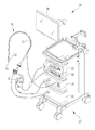
図1に示されるように、本発明による内視鏡検査システム10は、大腸等の消化管内に挿入される挿入部13と、その先端に設けられ管内内壁の状態を観察する観察窓41(図3参照)を有する先端部14と、先端部14に取り付けられ先端部14を消化管内で移動させる自己推進装置12とを備えた自走式内視鏡(以下、単に内視鏡という)15が用いられ、自己推進装置12に駆動力を与える動力装置16と、動力装置16に接続され自己推進装置12が移動する方向及び速度をコントロールするコントローラ17と、観察窓41で観察された画像を表示させるモニタ18とを備える。
As shown in FIG. 1, an
この他に、主として内視鏡15の電気的な作動を制御するプロセッサ装置20と、先端部14を洗浄するための洗浄水を送る輸液装置21と、体腔内を照明するための照明光を供給する光源装置22と、これらが組み付けられる内視鏡カート23を備える。コントローラ17は、自己推進装置12の前進・後退を指示する前進ボタン24と後退ボタン25、及び自己推進装置12の移動速度を設定する速度設定ボタン26とを備える。動力装置16は自己推進装置12の前進、後退、停止、速度などに関する駆動情報をプロセッサ装置20に伝達する。
In addition to this, a
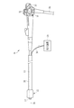
図2に示されるように、内視鏡15は、挿入部13と、内視鏡15の把持及び挿入部13の操作に用いられるアングルノブ31と送気・送水等の操作ボタン32とを備えた操作部33と、内視鏡15をプロセッサ装置20及び光源装置22に接続するユニバーサルコード34とを有する。ユニバーサルコード34は操作部33に接続され、送気・送水チャンネルと、撮像信号出力用ケーブル及びライトガイドが組み込まれている。
As shown in FIG. 2, the
また、挿入部13には、オーバーチューブ35が外嵌され、挿入部13とオーバーチューブ35との間に保護シース36が挿通されている。オーバーチューブ35は挿入部13の挿入軸30の方向に伸縮自在な蛇腹構造となっている。アングルノブ31は、挿入部13の湾曲方向及び湾曲量を調整する際に回転操作される。
Further, an
図3に示されるように、挿入部13は可撓性を有する棒状体で、先端部14の先端面に、観察窓41、照明窓42、送気・送水ノズル43等が設けられている。先端部14には超小型固体撮像素子(CCDセンサ、CMOSセンサ等)が搭載され、観察窓41を通して体腔内を観察し、観察した画像をモニタ18に表示する。モニタ18に表示された画像はプロセッサ装置20に内蔵されたRAM(記録装置)44(図4参照)に記録される。
As shown in FIG. 3, the
先端部14に取り付けられた自己推進装置12は消化管内で先端部14(及び挿入部13)を前進または後進させる。自己推進装置12はトルクワイヤ37によって動力装置16と接続され、動力装置16からトルクワイヤ37によって回転トルクが伝達される。トルクワイヤ37は、ほぼ全長に亘って保護シース36の内部に挿通されている。動力装置16の駆動力によりトルクワイヤ37は保護シース36内で回動する。
The self-
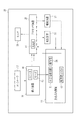
図4に示されるように、動力装置16はコントローラ17からの指示信号に従って内蔵されたモータ45を回転させ、モータ45の回転をトルクワイヤ37を介して自己推進装置12に伝達する。また、動力装置16はスピーカ46を内蔵し、自己推進装置12が駆動中の時は同時にスピーカ46から音を出して自己推進装置12が駆動中であること、即ち、内視鏡15の先端部14が移動していることを報知する。自己推進装置12の前進時と後退時では異なる音質の音で報知する。報知する音を自己推進装置12の移動速度によって変化させても良い。スピーカ46はスイッチ(図示せず)によってオフさせることができる。
As shown in FIG. 4, the
次に、内視鏡検査システム10の作用について説明する。挿入部13が大腸等の消化管内に挿入され、消化管内壁の状態が先端部14に設けられた観察窓41を通して観察される。観察された画像はモニタ18の表示画面50に映し出される。
Next, the operation of the
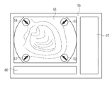
図5に示されるように、コントローラ17の前進ボタン24が操作されると、自己推進装置12によって先端部14が消化管内を前進し、先端部14の移動情報として、動力装置16からの情報がモニタ18の表示画面50内に設定された画像情報表示領域65の四隅のそれぞれに矢印図柄51〜54で表示される。矢印図柄51〜54は、それぞれの矢印の向きが画像情報表示領域65の四隅から略中心を向いた内向きに表示される。このときスピーカ46のスイッチをオンにしておけば、スピーカ46から前進中を示す音が報知される。
As shown in FIG. 5, when the
図6に示されるように、コントローラ17の後退ボタン25が操作されると、自己推進装置12によって先端部14が消化管内を後退し、先端部14の移動情報として、動力装置16からの情報がモニタ18の画像情報表示領域65の四隅のそれぞれに矢印図柄55〜58で表示される。矢印図柄55〜58は、それぞれの矢印の向きが画像情報表示領域65の略中心からそれぞれの角に向いた外向きに表示される。このときスピーカ46のスイッチをオンにしておけば、スピーカ46から後退中を示す音が報知される。
As shown in FIG. 6, when the backward button 25 of the
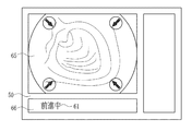
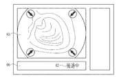
図7又は図8に示されるように、先端部14の移動情報として、モニタ18の表示画面50内に設定された文字表示領域66に、前進中61又は後退中62が表示されるようにしても良い。更に、図9に示されるように、モータ45の回転から算出した自己推進装置12の移動速度や自己推進装置12にかかる負荷トルクを動力装置16からプロセッサ装置20に伝送し、文字表示領域67に、それら(移動速度63、負荷トルク64)を表示するようにしても良い。
As shown in FIG. 7 or FIG. 8, forward movement 61 or backward movement 62 is displayed in the
画像情報表示領域65に表示された矢印図柄51〜58や文字表示領域66,67に表示された前進中61、後退中62、移動速度63、負荷トルク64などは、観察窓41を通して観察された体腔内の画像とともに画像情報としてプロセッサ装置20に内蔵されたRAM44に記録される。
The arrows 61 to 58 displayed in the image
前記実施形態において、スピーカ46は、動力装置16以外の場所に設置されたものであっても良く、駆動情報を含むモニタ18に表示された画像の記録はプロセッサ装置20に内蔵されたRAM44以外の記録装置に記録されるようにしても良い。
In the above-described embodiment, the
前記実施形態では、先行技術文献で挙げた特表2009−513250号公報に記載のトロイド袋体を有する自己推進装置と同様なものを内視鏡15の先端部14に装着した自走式内視鏡を用いて説明したが、これ以外の構造の自走式内視鏡でも良く、例えば、エンドレスベルトを用いた自己推進装置を搭載した自走式内視鏡であっても本発明を採用することは可能である。
In the above-described embodiment, a self-propelled endoscope in which the same device as the self-propelling device having the toroid bag described in JP 2009-513250 A mentioned in the prior art document is attached to the
10 内視鏡検査システム
12 自己推進装置
13 挿入部
14 先端部
15 内視鏡(自走式内視鏡)
16 動力装置
17 コントローラ
18 モニタ
20 プロセッサ装置
21 輸液装置
22 光源装置22
23 内視鏡カート
24 前進ボタン
25 後退ボタン
26 速度設定ボタン26
30 挿入軸
31 アングルノブ
32 操作ボタン
33 操作部
34 ユニバーサルコード
35 オーバーチューブ
36 保護シース
37 トルクワイヤ
41 観察窓
42 照明窓
43 送気・送水ノズル
44 RAM(記録装置)
45 モータ
46 スピーカ(報知器)
50 表示画面
51〜58 矢印図柄(駆動情報、画像情報)
61 前進中(駆動情報、文字情報)
62 後退中(駆動情報、文字情報)
63 移動速度(駆動情報、文字情報)
64 負荷トルク(駆動情報、文字情報)
65 画像情報表示領域
66,67 文字情報表示領域
DESCRIPTION OF
16
23
DESCRIPTION OF
45
50 Display screen 51-58 Arrow symbol (drive information, image information)
61 Moving forward (drive information, text information)
62 Backing (driving information, character information)
63 Movement speed (drive information, character information)
64 Load torque (drive information, text information)
65 Image
Claims (8)
前記自己推進装置に駆動力を与える動力装置と、
前記動力装置に接続され前記挿入部の体腔内での移動を指示するコントローラと、
前記挿入部の先端部に設けられた観察窓から観察された像が観察画像として表示されるとともに、前記動力装置の駆動情報が表示されるモニタと、
を備えたことを特徴とする内視鏡検査システム。 A self-propelled endoscope provided with a self-propelling device in an insertion portion to be inserted into a body cavity;
A power unit for applying a driving force to the self-propulsion unit;
A controller connected to the power unit and instructing movement of the insertion portion in a body cavity;
An image observed from an observation window provided at the distal end of the insertion portion is displayed as an observation image, and a monitor on which driving information of the power unit is displayed,
An endoscopy system characterized by comprising:
The endoscopy system according to any one of claims 1 to 7, further comprising a notification device that notifies different sounds depending on whether the driving force to the tip portion is forward or backward.
Priority Applications (2)
| Application Number | Priority Date | Filing Date | Title |
|---|---|---|---|
| JP2011056344A JP2012191978A (en) | 2011-03-15 | 2011-03-15 | Endoscopic examination system |
| US13/361,259 US20120238807A1 (en) | 2011-03-15 | 2012-01-30 | Endoscopy system |
Applications Claiming Priority (1)
| Application Number | Priority Date | Filing Date | Title |
|---|---|---|---|
| JP2011056344A JP2012191978A (en) | 2011-03-15 | 2011-03-15 | Endoscopic examination system |
Publications (1)
| Publication Number | Publication Date |
|---|---|
| JP2012191978A true JP2012191978A (en) | 2012-10-11 |
Family
ID=46828987
Family Applications (1)
| Application Number | Title | Priority Date | Filing Date |
|---|---|---|---|
| JP2011056344A Abandoned JP2012191978A (en) | 2011-03-15 | 2011-03-15 | Endoscopic examination system |
Country Status (2)
| Country | Link |
|---|---|
| US (1) | US20120238807A1 (en) |
| JP (1) | JP2012191978A (en) |
Cited By (3)
| Publication number | Priority date | Publication date | Assignee | Title |
|---|---|---|---|---|
| WO2014061566A1 (en) * | 2012-10-16 | 2014-04-24 | オリンパス株式会社 | Observation apparatus, observation assistance device, observation assistance method and program |
| WO2015125376A1 (en) * | 2014-02-19 | 2015-08-27 | オリンパス株式会社 | Display device |
| JP2016054841A (en) * | 2014-09-08 | 2016-04-21 | オリンパス株式会社 | Insertion device |
Families Citing this family (2)
| Publication number | Priority date | Publication date | Assignee | Title |
|---|---|---|---|---|
| DE112017002950T5 (en) * | 2016-06-13 | 2019-02-28 | Olympus Corporation | Introduction device, Ansetzwerkzeug and drive power transmission unit |
| CN117257467B (en) * | 2023-11-16 | 2024-02-06 | 北京云力境安科技有限公司 | Endoscope operation force determination device, computer device and readable storage medium |
Citations (7)
| Publication number | Priority date | Publication date | Assignee | Title |
|---|---|---|---|---|
| JP2005058430A (en) * | 2003-08-11 | 2005-03-10 | Olympus Corp | Medical device and medical device guiding system |
| JP2006087521A (en) * | 2004-09-21 | 2006-04-06 | Olympus Corp | Medical device guiding system and capsulated medical device |
| JP2006263167A (en) * | 2005-03-24 | 2006-10-05 | Olympus Corp | Medical device control system |
| WO2007080732A1 (en) * | 2006-01-13 | 2007-07-19 | Olympus Medical Systems Corp. | Endoscope system, program, and control method for endoscope system |
| WO2008099851A1 (en) * | 2007-02-14 | 2008-08-21 | Olympus Medical Systems Corp. | Operating device, monitor device, and capsule guiding system |
| JP2010009392A (en) * | 2008-06-27 | 2010-01-14 | Nikon Corp | Digital photo frame |
| JP2010103669A (en) * | 2008-10-22 | 2010-05-06 | Panasonic Corp | Imaging apparatus |
Family Cites Families (2)
| Publication number | Priority date | Publication date | Assignee | Title |
|---|---|---|---|---|
| US7623900B2 (en) * | 2005-09-02 | 2009-11-24 | Toshiba Medical Visualization Systems Europe, Ltd. | Method for navigating a virtual camera along a biological object with a lumen |
| EP2489394A4 (en) * | 2009-10-14 | 2013-07-31 | Nat Univ Corp Nagoya Inst Tech | Insertion device, training device, and recording system |
-
2011
- 2011-03-15 JP JP2011056344A patent/JP2012191978A/en not_active Abandoned
-
2012
- 2012-01-30 US US13/361,259 patent/US20120238807A1/en not_active Abandoned
Patent Citations (7)
| Publication number | Priority date | Publication date | Assignee | Title |
|---|---|---|---|---|
| JP2005058430A (en) * | 2003-08-11 | 2005-03-10 | Olympus Corp | Medical device and medical device guiding system |
| JP2006087521A (en) * | 2004-09-21 | 2006-04-06 | Olympus Corp | Medical device guiding system and capsulated medical device |
| JP2006263167A (en) * | 2005-03-24 | 2006-10-05 | Olympus Corp | Medical device control system |
| WO2007080732A1 (en) * | 2006-01-13 | 2007-07-19 | Olympus Medical Systems Corp. | Endoscope system, program, and control method for endoscope system |
| WO2008099851A1 (en) * | 2007-02-14 | 2008-08-21 | Olympus Medical Systems Corp. | Operating device, monitor device, and capsule guiding system |
| JP2010009392A (en) * | 2008-06-27 | 2010-01-14 | Nikon Corp | Digital photo frame |
| JP2010103669A (en) * | 2008-10-22 | 2010-05-06 | Panasonic Corp | Imaging apparatus |
Cited By (7)
| Publication number | Priority date | Publication date | Assignee | Title |
|---|---|---|---|---|
| WO2014061566A1 (en) * | 2012-10-16 | 2014-04-24 | オリンパス株式会社 | Observation apparatus, observation assistance device, observation assistance method and program |
| JP2014079377A (en) * | 2012-10-16 | 2014-05-08 | Olympus Corp | Observation apparatus, observation support apparatus, observation support method, and observation support program |
| WO2015125376A1 (en) * | 2014-02-19 | 2015-08-27 | オリンパス株式会社 | Display device |
| JP5905171B2 (en) * | 2014-02-19 | 2016-04-20 | オリンパス株式会社 | Display device |
| JPWO2015125376A1 (en) * | 2014-02-19 | 2017-03-30 | オリンパス株式会社 | Display device |
| US10004382B2 (en) | 2014-02-19 | 2018-06-26 | Olympus Corporation | Display apparatus |
| JP2016054841A (en) * | 2014-09-08 | 2016-04-21 | オリンパス株式会社 | Insertion device |
Also Published As
| Publication number | Publication date |
|---|---|
| US20120238807A1 (en) | 2012-09-20 |
Similar Documents
| Publication | Publication Date | Title |
|---|---|---|
| JP5384869B2 (en) | Endoscopic treatment system | |
| JP4884567B2 (en) | Endoscope system | |
| EP2394565B1 (en) | Medical system | |
| JP4398184B2 (en) | Endoscope | |
| US6162171A (en) | Robotic endoscope and an autonomous pipe robot for performing endoscopic procedures | |
| US8177709B2 (en) | Rotary self-propelled endoscope system | |
| JP4896264B2 (en) | Endoscope device | |
| EP1852052A1 (en) | Endoscope device | |
| AU2005292255A1 (en) | Automated control of irrigation and aspiration in a single-use endoscope | |
| JP2009045141A (en) | Endoscope insertion auxiliary tool and endoscope | |
| US20170224196A1 (en) | Medical drive device | |
| JP2012191978A (en) | Endoscopic examination system | |
| JP2014068817A (en) | Condition visually confirming device for endoscope | |
| Patel et al. | The endoscopy evolution:‘the superscope era’ | |
| WO2006129440A1 (en) | Endoscope device | |
| JP2006288751A (en) | Electric bending endoscopy instrument | |
| JP2017213367A5 (en) | Endoscope treatment tool drive wheel housing | |
| JP2013153819A (en) | Propulsion assisting apparatus for endoscope | |
| CA3179392A1 (en) | Robotic-assisted navigation and control for airway management procedures, assemblies and systems | |
| JP6081424B2 (en) | Ultrasound endoscope hood and ultrasound endoscope | |
| JP5484699B2 (en) | Endoscope insertion aid and endoscope apparatus | |
| JP4373262B2 (en) | Endoscope insertion assist device | |
| WO2023192129A1 (en) | Systems and methods for responsive insertion and retraction of robotic endoscope | |
| US20120046523A1 (en) | Self propelling device | |
| JP4445623B2 (en) | Endoscope device |
Legal Events
| Date | Code | Title | Description |
|---|---|---|---|
| A977 | Report on retrieval |
Free format text: JAPANESE INTERMEDIATE CODE: A971007 Effective date: 20130219 |
|
| A131 | Notification of reasons for refusal |
Free format text: JAPANESE INTERMEDIATE CODE: A131 Effective date: 20130227 |
|
| A762 | Written abandonment of application |
Free format text: JAPANESE INTERMEDIATE CODE: A762 Effective date: 20130417 |