WO2020152791A1 - Ultrasound endoscope and endoscope system - Google Patents
Ultrasound endoscope and endoscope system Download PDFInfo
- Publication number
- WO2020152791A1 WO2020152791A1 PCT/JP2019/001929 JP2019001929W WO2020152791A1 WO 2020152791 A1 WO2020152791 A1 WO 2020152791A1 JP 2019001929 W JP2019001929 W JP 2019001929W WO 2020152791 A1 WO2020152791 A1 WO 2020152791A1
- Authority
- WO
- WIPO (PCT)
- Prior art keywords
- ultrasonic
- angle
- endoscope
- ultrasonic transducer
- insertion portion
- Prior art date
Links
Images


Classifications
-
- A—HUMAN NECESSITIES
- A61—MEDICAL OR VETERINARY SCIENCE; HYGIENE
- A61B—DIAGNOSIS; SURGERY; IDENTIFICATION
- A61B8/00—Diagnosis using ultrasonic, sonic or infrasonic waves
- A61B8/44—Constructional features of the ultrasonic, sonic or infrasonic diagnostic device
- A61B8/4444—Constructional features of the ultrasonic, sonic or infrasonic diagnostic device related to the probe
- A61B8/4461—Features of the scanning mechanism, e.g. for moving the transducer within the housing of the probe
-
- A—HUMAN NECESSITIES
- A61—MEDICAL OR VETERINARY SCIENCE; HYGIENE
- A61B—DIAGNOSIS; SURGERY; IDENTIFICATION
- A61B1/00—Instruments for performing medical examinations of the interior of cavities or tubes of the body by visual or photographical inspection, e.g. endoscopes; Illuminating arrangements therefor
- A61B1/00002—Operational features of endoscopes
- A61B1/00043—Operational features of endoscopes provided with output arrangements
- A61B1/00045—Display arrangement
-
- A—HUMAN NECESSITIES
- A61—MEDICAL OR VETERINARY SCIENCE; HYGIENE
- A61B—DIAGNOSIS; SURGERY; IDENTIFICATION
- A61B1/00—Instruments for performing medical examinations of the interior of cavities or tubes of the body by visual or photographical inspection, e.g. endoscopes; Illuminating arrangements therefor
- A61B1/00064—Constructional details of the endoscope body
- A61B1/00071—Insertion part of the endoscope body
- A61B1/0008—Insertion part of the endoscope body characterised by distal tip features
- A61B1/00087—Tools
-
- A—HUMAN NECESSITIES
- A61—MEDICAL OR VETERINARY SCIENCE; HYGIENE
- A61B—DIAGNOSIS; SURGERY; IDENTIFICATION
- A61B1/00—Instruments for performing medical examinations of the interior of cavities or tubes of the body by visual or photographical inspection, e.g. endoscopes; Illuminating arrangements therefor
- A61B1/005—Flexible endoscopes
-
- A—HUMAN NECESSITIES
- A61—MEDICAL OR VETERINARY SCIENCE; HYGIENE
- A61B—DIAGNOSIS; SURGERY; IDENTIFICATION
- A61B1/00—Instruments for performing medical examinations of the interior of cavities or tubes of the body by visual or photographical inspection, e.g. endoscopes; Illuminating arrangements therefor
- A61B1/012—Instruments for performing medical examinations of the interior of cavities or tubes of the body by visual or photographical inspection, e.g. endoscopes; Illuminating arrangements therefor characterised by internal passages or accessories therefor
- A61B1/018—Instruments for performing medical examinations of the interior of cavities or tubes of the body by visual or photographical inspection, e.g. endoscopes; Illuminating arrangements therefor characterised by internal passages or accessories therefor for receiving instruments
-
- A—HUMAN NECESSITIES
- A61—MEDICAL OR VETERINARY SCIENCE; HYGIENE
- A61B—DIAGNOSIS; SURGERY; IDENTIFICATION
- A61B8/00—Diagnosis using ultrasonic, sonic or infrasonic waves
- A61B8/12—Diagnosis using ultrasonic, sonic or infrasonic waves in body cavities or body tracts, e.g. by using catheters
-
- A—HUMAN NECESSITIES
- A61—MEDICAL OR VETERINARY SCIENCE; HYGIENE
- A61B—DIAGNOSIS; SURGERY; IDENTIFICATION
- A61B8/00—Diagnosis using ultrasonic, sonic or infrasonic waves
- A61B8/44—Constructional features of the ultrasonic, sonic or infrasonic diagnostic device
- A61B8/4483—Constructional features of the ultrasonic, sonic or infrasonic diagnostic device characterised by features of the ultrasound transducer
- A61B8/4494—Constructional features of the ultrasonic, sonic or infrasonic diagnostic device characterised by features of the ultrasound transducer characterised by the arrangement of the transducer elements
-
- A—HUMAN NECESSITIES
- A61—MEDICAL OR VETERINARY SCIENCE; HYGIENE
- A61B—DIAGNOSIS; SURGERY; IDENTIFICATION
- A61B8/00—Diagnosis using ultrasonic, sonic or infrasonic waves
- A61B8/46—Ultrasonic, sonic or infrasonic diagnostic devices with special arrangements for interfacing with the operator or the patient
- A61B8/461—Displaying means of special interest
- A61B8/466—Displaying means of special interest adapted to display 3D data
-
- A—HUMAN NECESSITIES
- A61—MEDICAL OR VETERINARY SCIENCE; HYGIENE
- A61B—DIAGNOSIS; SURGERY; IDENTIFICATION
- A61B8/00—Diagnosis using ultrasonic, sonic or infrasonic waves
- A61B8/48—Diagnostic techniques
- A61B8/483—Diagnostic techniques involving the acquisition of a 3D volume of data
-
- A—HUMAN NECESSITIES
- A61—MEDICAL OR VETERINARY SCIENCE; HYGIENE
- A61B—DIAGNOSIS; SURGERY; IDENTIFICATION
- A61B90/00—Instruments, implements or accessories specially adapted for surgery or diagnosis and not covered by any of the groups A61B1/00 - A61B50/00, e.g. for luxation treatment or for protecting wound edges
- A61B90/06—Measuring instruments not otherwise provided for
-
- A—HUMAN NECESSITIES
- A61—MEDICAL OR VETERINARY SCIENCE; HYGIENE
- A61B—DIAGNOSIS; SURGERY; IDENTIFICATION
- A61B1/00—Instruments for performing medical examinations of the interior of cavities or tubes of the body by visual or photographical inspection, e.g. endoscopes; Illuminating arrangements therefor
- A61B1/00064—Constructional details of the endoscope body
- A61B1/00071—Insertion part of the endoscope body
- A61B1/0008—Insertion part of the endoscope body characterised by distal tip features
- A61B1/00082—Balloons
-
- A—HUMAN NECESSITIES
- A61—MEDICAL OR VETERINARY SCIENCE; HYGIENE
- A61B—DIAGNOSIS; SURGERY; IDENTIFICATION
- A61B90/00—Instruments, implements or accessories specially adapted for surgery or diagnosis and not covered by any of the groups A61B1/00 - A61B50/00, e.g. for luxation treatment or for protecting wound edges
- A61B90/06—Measuring instruments not otherwise provided for
- A61B2090/067—Measuring instruments not otherwise provided for for measuring angles
Landscapes
- Health & Medical Sciences (AREA)
- Life Sciences & Earth Sciences (AREA)
- Surgery (AREA)
- Engineering & Computer Science (AREA)
- General Health & Medical Sciences (AREA)
- Veterinary Medicine (AREA)
- Pathology (AREA)
- Public Health (AREA)
- Nuclear Medicine, Radiotherapy & Molecular Imaging (AREA)
- Animal Behavior & Ethology (AREA)
- Biomedical Technology (AREA)
- Heart & Thoracic Surgery (AREA)
- Medical Informatics (AREA)
- Molecular Biology (AREA)
- Biophysics (AREA)
- Physics & Mathematics (AREA)
- Radiology & Medical Imaging (AREA)
- Optics & Photonics (AREA)
- Gynecology & Obstetrics (AREA)
- Computer Graphics (AREA)
- General Engineering & Computer Science (AREA)
- Oral & Maxillofacial Surgery (AREA)
- Ultra Sonic Daignosis Equipment (AREA)
Abstract
This ultrasound endoscope is equipped with: a first hard part positioned at the distal end of an insertion section to be inserted into the interior of a body under examination; a support part connected to the proximal end side of the first hard part that forms an elongated shape along the length direction of the insertion section; a second hard part connected to the proximal end side of the support part; an ultrasound transducer fixed to the support part and comprising a plurality of piezoelectric elements arranged along the length direction of the insertion section; and a rotating mechanism causing the support part and the ultrasound transducer to rotate as a single body. Provided in this manner is an ultrasound endoscope having a wide observation range.
Description
本発明は、超音波内視鏡及び内視鏡システムに関する。
The present invention relates to an ultrasonic endoscope and an endoscope system.
従来、柔軟で細長い挿入部を人等の被検体内に挿入し、当該挿入部の先端側に設けられた超音波振動子にて超音波を送受信することにより、当該被検体内を観察する超音波内視鏡が知られている(例えば、特許文献1参照)。さらに、超音波内視鏡と、超音波内視鏡が送受信した超音波を変換した電気的なエコー信号を受信して超音波画像を生成する超音波観測装置と、を備える内視鏡システムが知られている。
Conventionally, a flexible and elongated insertion part is inserted into a subject such as a person, and ultrasonic waves are transmitted and received by an ultrasonic transducer provided on the distal end side of the insertion part to observe the inside of the subject. A sound wave endoscope is known (for example, refer to Patent Document 1). Furthermore, an endoscope system including an ultrasonic endoscope and an ultrasonic observation apparatus that receives an electric echo signal obtained by converting an ultrasonic wave transmitted and received by the ultrasonic endoscope to generate an ultrasonic image is provided. Are known.
しかしながら、超音波観測装置が生成する超音波画像は、2次元の断面画像であるため、観察できる範囲が狭いため、臓器や病変を特定するのが必ずしも容易ではない。
However, since the ultrasonic image generated by the ultrasonic observation device is a two-dimensional cross-sectional image, the observable range is narrow, so it is not always easy to identify the organ or lesion.
本発明は、上記に鑑みてなされたものであって、超音波画像により観察可能な範囲が広い超音波内視鏡及び内視鏡システムを提供することを目的とする。
The present invention has been made in view of the above, and an object of the present invention is to provide an ultrasonic endoscope and an endoscope system in which an ultrasonic image can be observed in a wide range.
上述した課題を解決し、目的を達成するために、本発明の一態様に係る超音波内視鏡は、被検体内に挿入される挿入部の先端に位置する第1硬性部と、前記第1硬性部の基端側に接続されており、前記挿入部の長手方向に沿って長尺状をなす支持部と、前記支持部の基端側に接続されている第2硬性部と、前記支持部に固定されており、前記挿入部の長手方向に沿って複数の圧電素子が配列されてなる超音波振動子と、前記支持部及び前記超音波振動子を一体的に回転させる回転機構と、を備える。
In order to solve the above-mentioned problems and achieve the object, an ultrasonic endoscope according to an aspect of the present invention includes a first rigid portion located at a tip of an insertion portion inserted into a subject, and the first rigid portion. 1 a rigid portion, which is connected to the proximal end side, is elongated along the longitudinal direction of the insertion portion, a second rigid portion, which is connected to the proximal end side of the supporting portion, An ultrasonic transducer fixed to a support portion, in which a plurality of piezoelectric elements are arranged along the longitudinal direction of the insertion portion, and a rotation mechanism for integrally rotating the support portion and the ultrasonic transducer. , Is provided.
また、本発明の一態様に係る超音波内視鏡は、前記第1硬性部に設けられており、前記挿入部の長手方向に沿った方向を撮像する撮像部を備える。
Further, the ultrasonic endoscope according to an aspect of the present invention includes an imaging unit which is provided in the first rigid portion and which images a direction along the longitudinal direction of the insertion portion.
また、本発明の一態様に係る超音波内視鏡は、前記第2硬性部に設けられており、前記挿入部の長手方向と交差する方向を撮像する撮像部を備える。
Further, the ultrasonic endoscope according to one aspect of the present invention includes an imaging unit that is provided in the second rigid portion and that captures an image in a direction intersecting the longitudinal direction of the insertion portion.
また、本発明の一態様に係る超音波内視鏡は、前記第2硬性部には、基端側から挿入された処置具を前記挿入部の長手方向に沿って突出させる処置具突出口が形成されている。
Further, in the ultrasonic endoscope according to one aspect of the present invention, the second rigid portion has a treatment instrument projecting port for projecting the treatment instrument inserted from the proximal end side along the longitudinal direction of the insertion portion. Has been formed.
また、本発明の一態様に係る超音波内視鏡は、前記第1硬性部には、基端側から挿入された処置具を前記挿入部の長手方向に沿って突出させる処置具突出口が形成されている。
Further, in the ultrasonic endoscope according to one aspect of the present invention, the first rigid portion has a treatment instrument projecting port configured to project the treatment instrument inserted from the proximal end side along the longitudinal direction of the insertion portion. Has been formed.
また、本発明の一態様に係る超音波内視鏡は、前記第1硬性部及び前記第2硬性部には、バルーンバンドを係止するバルーン溝が形成されている。
Further, in the ultrasonic endoscope according to one aspect of the present invention, a balloon groove for locking a balloon band is formed in the first rigid portion and the second rigid portion.
また、本発明の一態様に係る超音波内視鏡は、前記超音波振動子には、前記回転機構の動力を伝達するフレキシブルシャフトが接続されている。
Further, in the ultrasonic endoscope according to one aspect of the present invention, a flexible shaft for transmitting power of the rotating mechanism is connected to the ultrasonic transducer.
また、本発明の一態様に係る超音波内視鏡は、前記フレキシブルシャフトの内部には、前記超音波振動子の各圧電素子に接続されている複数の信号線が挿通されている。
Further, in the ultrasonic endoscope according to one aspect of the present invention, a plurality of signal lines connected to each piezoelectric element of the ultrasonic transducer is inserted inside the flexible shaft.
また、本発明の一態様に係る超音波内視鏡は、前記超音波振動子は、前記複数の圧電素子の長手方向が、前記挿入部の長手方向と直交しており、曲面をなして配列されているコンベックス型の超音波振動子である。
Further, in the ultrasonic endoscope according to one aspect of the present invention, in the ultrasonic transducer, a longitudinal direction of the plurality of piezoelectric elements is orthogonal to a longitudinal direction of the insertion portion, and the ultrasonic transducers are arranged in a curved surface. It is a convex type ultrasonic transducer.
また、本発明の一態様に係る超音波内視鏡は、前記第1硬性部は、樹脂からなる。
Further, in the ultrasonic endoscope according to one aspect of the present invention, the first rigid portion is made of resin.
また、本発明の一態様に係る超音波内視鏡は、前記回転機構は、前記超音波振動子を回転させるモータである。
In the ultrasonic endoscope according to one aspect of the present invention, the rotating mechanism is a motor that rotates the ultrasonic transducer.
また、本発明の一態様に係る超音波内視鏡は、前記回転機構より先端側に設けられており、前記超音波振動子が回転する方向の角度を検出する角度センサを備える。
The ultrasonic endoscope according to one aspect of the present invention includes an angle sensor that is provided on the tip side of the rotation mechanism and that detects the angle of the direction in which the ultrasonic transducer rotates.
また、本発明の一態様に係る超音波内視鏡は、前記超音波振動子の回転方向における角度を表示する角度表示部を備える。
Also, the ultrasonic endoscope according to one aspect of the present invention includes an angle display unit that displays an angle in the rotation direction of the ultrasonic transducer.
また、本発明の一態様に係る超音波内視鏡は、前記角度表示部は、前記挿入部の長手方向に沿って、該挿入部を投影した面積が最小となる前記超音波振動子の角度を示す第1の目印を有する。
Further, in the ultrasonic endoscope according to one aspect of the present invention, the angle display unit is an angle of the ultrasonic transducer that minimizes an area projected along the longitudinal direction of the insertion unit. Has a first mark indicating.
また、本発明の一態様に係る超音波内視鏡は、前記回転機構より先端側に設けられており、前記超音波振動子が回転する方向の角度を検出する角度センサと、前記超音波振動子が回転する方向の角度を表示する角度表示部と、を備え、前記角度表示部は、前記処置具突出口から突出した前記処置具が前記超音波振動子に接触しない前記超音波振動子の角度を示す第2の目印を有する。
An ultrasonic endoscope according to one aspect of the present invention is provided on the tip side of the rotating mechanism, and has an angle sensor that detects an angle in a direction in which the ultrasonic vibrator rotates, and the ultrasonic vibration. An angle display section for displaying the angle of the direction in which the child rotates, the angle display section of the ultrasonic transducer in which the treatment tool protruding from the treatment tool projecting port does not contact the ultrasonic transducer. It has a second mark indicating the angle.
また、本発明の一態様に係る内視鏡システムは、超音波内視鏡と、前記超音波内視鏡に電気的なパルス信号を送信し、超音波を照射させるとともに、前記超音波内視鏡が受信した超音波エコーを変換した電気的なエコー信号を受信して、超音波画像を生成する超音波観測装置と、を備える。
Further, the endoscope system according to an aspect of the present invention is an ultrasonic endoscope, and transmits an electrical pulse signal to the ultrasonic endoscope to irradiate ultrasonic waves, and the ultrasonic endoscope An ultrasonic observation device that receives an electrical echo signal obtained by converting an ultrasonic echo received by the mirror and generates an ultrasonic image.
また、本発明の一態様に係る内視鏡システムは、前記回転機構より先端側に設けられており、前記超音波振動子が回転する方向の角度を検出する角度センサを備え、前記超音波観測装置は、前記角度センサが検出した角度に応じて前記超音波画像を合成した3次元画像を生成する。
The endoscope system according to an aspect of the present invention includes an angle sensor that is provided on a tip side of the rotation mechanism and that detects an angle in a direction in which the ultrasonic transducer rotates, and the ultrasonic observation The device generates a three-dimensional image in which the ultrasonic images are combined according to the angle detected by the angle sensor.
また、本発明の一態様に係る内視鏡システムは、前記超音波観測装置は、前記角度センサが検出した角度を表示装置に表示させる。
Further, in the endoscope system according to the aspect of the present invention, the ultrasonic observation device causes the display device to display the angle detected by the angle sensor.
また、本発明の一態様に係る内視鏡システムは、前記挿入部の長手方向に沿って、該挿入部を投影した面積が最小となる前記超音波振動子の角度を表示装置に表示させる。
Further, the endoscope system according to the aspect of the present invention causes the display device to display the angle of the ultrasonic transducer that minimizes the projected area of the insertion portion along the longitudinal direction of the insertion portion.
また、本発明の一態様に係る内視鏡システムは、前記第2硬性部には、基端側から挿入された処置具を前記挿入部の長手方向に沿って突出させる処置具突出口が形成されており、前記超音波観測装置は、前記処置具突出口から突出した前記処置具が前記超音波振動子に接触しない前記超音波振動子の角度を表示装置に表示させる。
Further, in the endoscope system according to the aspect of the present invention, the second rigid portion is provided with a treatment instrument projecting port for projecting the treatment instrument inserted from the proximal end side along the longitudinal direction of the insertion section. The ultrasonic observation device causes the display device to display the angle of the ultrasonic transducer in which the treatment tool protruding from the treatment tool protruding port does not contact the ultrasonic vibrator.
本発明によれば、超音波画像により観察可能な範囲が広い超音波内視鏡及び内視鏡システムを実現することができる。
According to the present invention, it is possible to realize an ultrasonic endoscope and an endoscope system in which an ultrasonic image can be observed in a wide range.
以下に、図面を参照して本発明に係る超音波内視鏡及び内視鏡システムの実施の形態を説明する。なお、これらの実施の形態により本発明が限定されるものではない。本発明は、超音波振動子を備える超音波内視鏡及び内視鏡システム一般に適用することができる。
Embodiments of an ultrasonic endoscope and an endoscope system according to the present invention will be described below with reference to the drawings. The present invention is not limited to these embodiments. The present invention can be applied to an ultrasonic endoscope including an ultrasonic transducer and an endoscope system in general.
また、図面の記載において、同一又は対応する要素には適宜同一の符号を付している。また、図面は模式的なものであり、各要素の寸法の関係、各要素の比率などは、現実と異なる場合があることに留意する必要がある。図面の相互間においても、互いの寸法の関係や比率が異なる部分が含まれている場合がある。
Also, in the description of the drawings, the same or corresponding elements are appropriately assigned the same reference numerals. Further, it should be noted that the drawings are schematic, and the dimensional relationship of each element, the ratio of each element, and the like may differ from reality. Even between the drawings, there are cases where parts having different dimensional relationships and ratios are included.
(実施の形態)
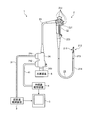
図1は、本発明の実施の形態に係る超音波内視鏡を含む内視鏡システムを模式的に示す図である。内視鏡システム1は、超音波内視鏡を用いて人等の被検体内の超音波診断を行うシステムである。この内視鏡システム1は、図1に示すように、超音波内視鏡2と、超音波観測装置3と、内視鏡観察装置4と、表示装置5と、光源装置6と、を備える。 (Embodiment)
FIG. 1 is a diagram schematically showing an endoscope system including an ultrasonic endoscope according to an embodiment of the present invention. Theendoscope system 1 is a system that performs ultrasonic diagnosis in a subject such as a person using an ultrasonic endoscope. As shown in FIG. 1, the endoscope system 1 includes an ultrasonic endoscope 2, an ultrasonic observation device 3, an endoscope observation device 4, a display device 5, and a light source device 6. ..
図1は、本発明の実施の形態に係る超音波内視鏡を含む内視鏡システムを模式的に示す図である。内視鏡システム1は、超音波内視鏡を用いて人等の被検体内の超音波診断を行うシステムである。この内視鏡システム1は、図1に示すように、超音波内視鏡2と、超音波観測装置3と、内視鏡観察装置4と、表示装置5と、光源装置6と、を備える。 (Embodiment)
FIG. 1 is a diagram schematically showing an endoscope system including an ultrasonic endoscope according to an embodiment of the present invention. The
超音波内視鏡2は、その先端部に設けられた超音波振動子によって、超音波観測装置3から受信した電気的なパルス信号を超音波パルス(音響パルス)に変換して被検体へ照射するとともに、被検体で反射された超音波エコーを電圧変化で表現する電気的なエコー信号に変換して出力する。
The ultrasonic endoscope 2 converts an electrical pulse signal received from the ultrasonic observation device 3 into an ultrasonic pulse (acoustic pulse) and irradiates the subject with an ultrasonic transducer provided at the tip thereof. At the same time, the ultrasonic echo reflected by the subject is converted into an electric echo signal represented by a voltage change and output.
超音波内視鏡2は、撮像光学系及び撮像素子を有しており、被検体の消化管(食道、胃、十二指腸、大腸)、又は呼吸器(気管、気管支)へ挿入され、消化管や、呼吸器の撮像を行うことが可能である。また、超音波内視鏡2は、撮像時に被検体へ照射する照明光を導くライトガイドを有する。このライトガイドは、先端部が超音波内視鏡2の被検体への挿入部の先端まで達している一方、基端部が照明光を発生する光源装置6に接続されている。また、超音波内視鏡2は、消化管や、呼吸器の周囲臓器(膵臓、胆嚢、胆管、胆道、リンパ節、縦隔臓器、血管等)に対して、超音波を送信し、該周辺臓器で反射した超音波を受信する。
The ultrasonic endoscope 2 has an imaging optical system and an imaging device, and is inserted into the digestive tract (esophagus, stomach, duodenum, large intestine) or respiratory organ (trachea, bronchus) of a subject to , It is possible to perform respiratory imaging. In addition, the ultrasonic endoscope 2 has a light guide that guides the illumination light with which the subject is irradiated during imaging. The light guide has a distal end reaching the distal end of the insertion portion of the ultrasonic endoscope 2 into the subject, and a proximal end connected to a light source device 6 for generating illumination light. Further, the ultrasonic endoscope 2 transmits ultrasonic waves to the digestive tract and peripheral organs of the respiratory system (pancreas, gallbladder, bile duct, biliary tract, lymph nodes, mediastinal organs, blood vessels, etc.), and the surroundings. Receive the ultrasonic waves reflected by the organ.
超音波内視鏡2は、図1に示すように、挿入部21と、操作部22と、ユニバーサルコード23と、コネクタ24と、を備える。挿入部21は、被検体内に挿入される部分である。この挿入部21は、図1に示すように、先端側に設けられ、超音波振動子211を保持する先端部212と、先端部212の基端側に連結され湾曲可能とする湾曲部213と、湾曲部213の基端側に連結され可撓性を有する可撓管部214と、を備える。
As shown in FIG. 1, the ultrasonic endoscope 2 includes an insertion portion 21, an operation portion 22, a universal cord 23, and a connector 24. The insertion portion 21 is a portion to be inserted into the subject. As shown in FIG. 1, the insertion portion 21 includes a distal end portion 212 that is provided on the distal end side and holds the ultrasonic transducer 211, and a bending portion 213 that is connected to the proximal end side of the distal end portion 212 and is bendable. And a flexible tube portion 214 which is connected to the base end side of the bending portion 213 and has flexibility.
超音波振動子211は、挿入部21の長手方向に沿って複数の圧電素子が配列されてなる。具体的には、複数の圧電素子の長手方向が、挿入部21の長手方向と直交しており、曲面をなして配列されているコンベックス型の超音波振動子211である。また、各圧電素子には、後述するフレキシブルシャフト211a(図5参照)及び複数の信号線211b(図5参照)が接続されている。複数の圧電素子には、必要に応じて音響整合層(図示せず)、音響レンズ211c(図4参照)、バッキング材(図示せず)が取り付けられており、各圧電素子において発生した超音波は音響レンズ211cを通して被検体に向かって照射される。また、複数の圧電素子を含む各構成は、ハウジング211d(図2参照)に収容されている。ただし、超音波振動子211は、複数の圧電素子が平面をなして配列されているリニア型であってもよい。なお、超音波振動子211がコンベックス型である場合、複数の圧電素子から放射状に超音波を照射するため、観察可能な範囲が広い。一方、超音波振動子211がリニア型の場合、挿入部21の先端をコンベックス型よりも細くすることが可能である。超音波内視鏡2は、送受信にかかわる圧電素子を電子的に切り替えたり、各圧電素子の送受信に遅延をかけたりすることで、電子的に走査させる。挿入部21の先端の詳細な説明は後述する。
The ultrasonic transducer 211 has a plurality of piezoelectric elements arranged along the longitudinal direction of the insertion portion 21. Specifically, the convex type ultrasonic transducers 211 are arranged such that the longitudinal directions of the plurality of piezoelectric elements are orthogonal to the longitudinal direction of the insertion portion 21 and are arranged in a curved surface. Further, a flexible shaft 211a (see FIG. 5) and a plurality of signal lines 211b (see FIG. 5) described later are connected to each piezoelectric element. An acoustic matching layer (not shown), an acoustic lens 211c (see FIG. 4), and a backing material (not shown) are attached to the plurality of piezoelectric elements as necessary, and ultrasonic waves generated in each piezoelectric element are attached. Is emitted toward the subject through the acoustic lens 211c. Further, each structure including a plurality of piezoelectric elements is housed in a housing 211d (see FIG. 2). However, the ultrasonic transducer 211 may be a linear type in which a plurality of piezoelectric elements are arranged in a plane. When the ultrasonic transducer 211 is of the convex type, ultrasonic waves are radially emitted from a plurality of piezoelectric elements, so that the observable range is wide. On the other hand, when the ultrasonic transducer 211 is a linear type, the tip of the insertion portion 21 can be made thinner than the convex type. The ultrasonic endoscope 2 scans electronically by electronically switching piezoelectric elements involved in transmission/reception or delaying transmission/reception of each piezoelectric element. A detailed description of the tip of the insertion portion 21 will be described later.
操作部22は、挿入部21の基端側に連結され、医師等の操作者からの各種操作を受け付ける部分である。この操作部22は、図1に示すように、湾曲部213を湾曲操作するための湾曲ノブ221と、各種操作を行うための複数の操作部材222と、を備える。また、操作部22には、処置具用挿通路に連通し、当該処置具用挿通路に処置具を挿通するための処置具挿入口223が形成されている。
The operation section 22 is a section that is connected to the proximal end side of the insertion section 21 and receives various operations from an operator such as a doctor. As shown in FIG. 1, the operation section 22 includes a bending knob 221 for bending the bending section 213 and a plurality of operation members 222 for performing various operations. Further, the operation portion 22 is formed with a treatment instrument insertion opening 223 for communicating with the treatment instrument insertion passage and inserting the treatment instrument in the treatment instrument insertion passage.
ユニバーサルコード23は、操作部22から延在し、各種信号を伝送する複数の信号ケーブル、及び光源装置6から供給された照明光を伝送する光ファイバ等が配設されたケーブルである。
The universal cord 23 is a cable extending from the operation unit 22 and provided with a plurality of signal cables for transmitting various signals, an optical fiber for transmitting the illumination light supplied from the light source device 6, and the like.
コネクタ24は、ユニバーサルコード23の先端に設けられている。そして、コネクタ24は、超音波ケーブル31、ビデオケーブル41、及び光源装置6がそれぞれ接続される第1~第3コネクタ部241~243を備える。
The connector 24 is provided at the tip of the universal cord 23. The connector 24 includes first to third connector portions 241 to 243 to which the ultrasonic cable 31, the video cable 41 and the light source device 6 are respectively connected.
超音波観測装置3は、超音波ケーブル31(図1参照)を経由して超音波内視鏡2に電気的に接続し、超音波ケーブル31を経由して超音波内視鏡2に電気的なパルス信号を送信し、超音波内視鏡2に超音波を照射させるとともに、超音波内視鏡2が受信した超音波エコーを変換した電気的なエコー信号を受信して、超音波画像を生成する。
The ultrasonic observation device 3 is electrically connected to the ultrasonic endoscope 2 via the ultrasonic cable 31 (see FIG. 1) and electrically connected to the ultrasonic endoscope 2 via the ultrasonic cable 31. A pulse signal to transmit ultrasonic waves to the ultrasonic endoscope 2 and receive an electrical echo signal obtained by converting an ultrasonic echo received by the ultrasonic endoscope 2 to generate an ultrasonic image. To generate.
内視鏡観察装置4は、ビデオケーブル41(図1参照)を介して超音波内視鏡2に電気的に接続し、ビデオケーブル41を介して超音波内視鏡2からの画像信号を入力する。そして、内視鏡観察装置4は、当該画像信号に所定の処理を施して内視鏡画像を生成する。
The endoscope observation device 4 is electrically connected to the ultrasonic endoscope 2 via a video cable 41 (see FIG. 1), and inputs an image signal from the ultrasonic endoscope 2 via the video cable 41. To do. Then, the endoscopic observation device 4 performs a predetermined process on the image signal to generate an endoscopic image.
表示装置5は、液晶又は有機EL(Electro Luminescence)、プロジェクタ、CRT(Cathode Ray Tube)などを用いて構成され、超音波観測装置3にて生成された超音波画像や、内視鏡観察装置4にて生成された内視鏡画像等を表示する。
The display device 5 is configured by using a liquid crystal or an organic EL (Electro Luminescence), a projector, a CRT (Cathode Ray Tube), and the like, and the ultrasonic image generated by the ultrasonic observation device 3 and the endoscope observation device 4 The endoscopic image and the like generated in step 3 is displayed.
光源装置6は、超音波内視鏡2に接続し、被検体内を照明する照明光を超音波内視鏡2に供給する。
The light source device 6 is connected to the ultrasonic endoscope 2 and supplies illumination light for illuminating the inside of the subject to the ultrasonic endoscope 2.
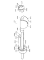
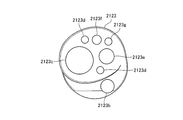
次に、挿入部21の詳細な構成を説明する。図2は、超音波内視鏡の先端部を側面から見た様子を表す図である。図2に示すように、超音波内視鏡2は、被検体内に挿入される挿入部21の先端に位置する第1硬性部2121と、第1硬性部2121の基端側に接続されている支持部2122と、支持部2122の基端側に接続されている第2硬性部2123と、を備える。
Next, the detailed configuration of the insertion unit 21 will be described. FIG. 2 is a diagram showing a state in which the distal end portion of the ultrasonic endoscope is viewed from the side surface. As shown in FIG. 2, the ultrasonic endoscope 2 is connected to the first rigid portion 2121 located at the tip of the insertion portion 21 inserted into the subject and the proximal end side of the first rigid portion 2121. And a second rigid portion 2123 connected to the base end side of the support portion 2122.
第1硬性部2121及び第2硬性部2123には、バルーンに設けられたバルーンバンドを係止することによりバルーンを超音波内視鏡2に取り付けるための第1バンド溝2121a及び第2バンド溝2123aがそれぞれ形成されている。
A first band groove 2121a and a second band groove 2123a for attaching the balloon to the ultrasonic endoscope 2 by locking a balloon band provided on the balloon on the first rigid portion 2121 and the second rigid portion 2123. Are formed respectively.
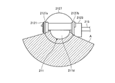
図3は、図2にバルーンを取り付けた状態を表す図である。図3に示すように、筒状のバルーン2127の先端側のバルーンバンド2127aが第1バンド溝2121aに嵌合され、基端側のバルーンバンド2127bが第2バンド溝2123aに嵌合され、バルーン2127が超音波振動子211を覆うように挿入部21の先端に取り付けられる。バルーン2127が挿入部21に取り付けられた状態で、バルーン給排水管路2123dから水等の液体をバルーン内に充填すると、バルーン2127が膨らむ。超音波観測装置3による制御のもと、超音波振動子211を駆動すると、図3に示すように、複数の圧電素子の配列方向に沿った断面により構成される領域Aにおける超音波画像を生成することができる。
FIG. 3 is a diagram showing a state in which a balloon is attached to FIG. As shown in FIG. 3, the distal end side balloon band 2127a of the tubular balloon 2127 is fitted into the first band groove 2121a, and the proximal end side balloon band 2127b is fitted into the second band groove 2123a. Is attached to the tip of the insertion portion 21 so as to cover the ultrasonic transducer 211. When the balloon 2127 is attached to the insertion portion 21, when the liquid such as water is filled into the balloon from the balloon water supply/drainage conduit 2123d, the balloon 2127 is inflated. When the ultrasonic transducer 211 is driven under the control of the ultrasonic observation device 3, as shown in FIG. 3, an ultrasonic image in a region A formed by a cross section along the arrangement direction of a plurality of piezoelectric elements is generated. can do.
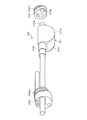
図4は、図1に示す超音波内視鏡の先端部を先端側から見た斜視図である。図5は、図1に示す超音波内視鏡の先端部を基端側から見た斜視図である。図6は、図4を分解した様子を表す図である。図7は、図5を分解した様子を表す図である。
FIG. 4 is a perspective view of the distal end portion of the ultrasonic endoscope shown in FIG. 1 viewed from the distal end side. FIG. 5 is a perspective view of the distal end portion of the ultrasonic endoscope shown in FIG. 1 as viewed from the proximal end side. FIG. 6 is a diagram showing a state in which FIG. 4 is disassembled. FIG. 7 is a diagram showing a state in which FIG. 5 is disassembled.
第1硬性部2121の先端には、挿入部21の長手方向に沿った方向を撮像する撮像部2124と、光源装置6から供給される照明光を被検体内に照射する照明部2125と、挿入部21の先端から撮像部2124に向けて水等の液体を送出することにより撮像部2124に付着した汚れの除去などを行うためのノズル2126とが設けられている。
At the tip of the first rigid portion 2121, an imaging unit 2124 that captures an image in a direction along the longitudinal direction of the insertion unit 21, an illumination unit 2125 that illuminates the inside of the subject with illumination light supplied from the light source device 6, A nozzle 2126 is provided for removing stains adhering to the imaging unit 2124 by sending a liquid such as water from the tip of the unit 21 toward the imaging unit 2124.
図5に示すように、超音波振動子211には、回転機構の動力を伝達するフレキシブルシャフト211aが接続されている。そして、フレキシブルシャフト211aの内部には、超音波振動子211の各圧電素子に対して電気的に接続されている複数の信号線211bが挿通されている。フレキシブルシャフト211aは、例えばコイル状の金属部材であり、回転機構の動力により回転して、先端に固定された超音波振動子211を回転させる。このとき、フレキシブルシャフト211aと複数の信号線211bとは、一体的に回転する。フレキシブルシャフト211aの内部に信号線211bを挿通することにより、フレキシブルシャフト211a内のスペースを有効活用することができ、挿入部21を細くすることができる。なお、信号線211bは、必ずしもフレキシブルシャフト211aの内部を挿通する必要はなく、フレキシブルシャフトの外部に配置するようにしてもよい。このようにすることで、細長いフレキシブルシャフト211aの内部に複数の信号線211bを挿通させる作業をなくすことができる。また、フレキシブルシャフト211aと第2硬性部2123との間に軸受などの回転支持部材を設けることにより、フレキシブルシャフト211aが第2硬性部2123に対して、滑らかに回転するようにしてもよい。
As shown in FIG. 5, a flexible shaft 211a that transmits the power of the rotating mechanism is connected to the ultrasonic transducer 211. A plurality of signal lines 211b electrically connected to each piezoelectric element of the ultrasonic transducer 211 are inserted inside the flexible shaft 211a. The flexible shaft 211a is, for example, a coil-shaped metal member, and is rotated by the power of the rotating mechanism to rotate the ultrasonic transducer 211 fixed to the tip. At this time, the flexible shaft 211a and the plurality of signal lines 211b rotate integrally. By inserting the signal line 211b into the flexible shaft 211a, the space in the flexible shaft 211a can be effectively used and the insertion portion 21 can be made thin. The signal line 211b does not necessarily have to pass through the inside of the flexible shaft 211a, and may be arranged outside the flexible shaft. By doing so, the work of inserting the plurality of signal lines 211b into the elongated flexible shaft 211a can be eliminated. Further, a flexible support member such as a bearing may be provided between the flexible shaft 211a and the second rigid portion 2123 so that the flexible shaft 211a can smoothly rotate with respect to the second rigid portion 2123.
第1硬性部2121は、例えば樹脂からなるが、材料は特に限定されず、金属や合金からなる構成であってもよい。超音波内視鏡2では、超音波振動子211にバルーン2127を被せて、バルーン2127内に脱気水などの液体を充満させた状態で、バルーン2127を生体組織に接触させることにより、超音波振動子211から生体組織に向かって超音波が伝達しやすくする。第1硬性部2121の基端側には、支持部2122の先端が嵌合する凹部2121b(図7参照)が形成されている。支持部2122と凹部2121bとの間には、軸受などの回転支持部材を設けることにより、超音波振動子211が滑らかに回転するようにしてもよい。
The first hard part 2121 is made of, for example, resin, but the material is not particularly limited and may be made of metal or alloy. In the ultrasonic endoscope 2, the ultrasonic transducer 211 is covered with a balloon 2127, and the balloon 2127 is filled with a liquid such as degassed water. The ultrasonic waves are easily transmitted from the oscillator 211 to the living tissue. A concave portion 2121b (see FIG. 7) into which the tip of the support portion 2122 is fitted is formed on the proximal end side of the first rigid portion 2121. A rotary support member such as a bearing may be provided between the support portion 2122 and the recess 2121b so that the ultrasonic transducer 211 can smoothly rotate.
支持部2122は、挿入部21の長手方向に沿って長尺状をなす棒状の部材である。支持部2122は、例えば金属や合金からなるが、材料は特に限定されない。支持部2122には、フレキシブルシャフト211aの回転に伴って、回転するようにフレキシブルシャフト211aが取り付けられている。また、支持部2122には、超音波振動子211が固定されている。したがって、フレキシブルシャフト211aの回転に伴って、支持部2122及び超音波振動子211を一体的に回転させることができる。支持部2122の先端には、第1硬性部2121の凹部2121bに嵌合する凸部2122aが形成されている。なお、第1硬性部2121に凸部が形成されており、支持部2122に凹部が形成されていてもよい。
The support portion 2122 is a rod-shaped member that is elongated along the longitudinal direction of the insertion portion 21. The support portion 2122 is made of, for example, a metal or an alloy, but the material is not particularly limited. The flexible shaft 211a is attached to the support portion 2122 so as to rotate as the flexible shaft 211a rotates. The ultrasonic transducer 211 is fixed to the support portion 2122. Therefore, the support portion 2122 and the ultrasonic transducer 211 can be integrally rotated with the rotation of the flexible shaft 211a. A convex portion 2122a that fits into the concave portion 2121b of the first rigid portion 2121 is formed at the tip of the support portion 2122. It should be noted that the first hard part 2121 may be formed with a convex part and the support part 2122 may be formed with a concave part.
第2硬性部2123は、例えば樹脂からなるが材料は特に限定されない。また、第2硬性部2123には、基端側から挿入された処置具を挿入部21の長手方向に沿って突出させる処置具突出口2123bが形成されている。処置具突出口2123bは、処置具用挿通路に連通するように設けられている。処置具突出口2123bには、鉗子起上機構(図示せず)を設けることで、処置具突出口2123bから突出した処置具の向きを超音波振動子211が超音波を放射する方向に誘導できるようにしてもよい。第2硬性部2123には、支持部2122の基端が挿入される振動子用管路2123cが設けられる。支持部2122と振動子用管路2123cとの間には軸受などの回転支持部材を設けることで、滑らかに回転するようにしてもよい。
The second hard part 2123 is made of resin, for example, but the material is not particularly limited. Further, the second rigid portion 2123 is formed with a treatment instrument projecting port 2123b for projecting the treatment instrument inserted from the proximal end side along the longitudinal direction of the insertion section 21. The treatment instrument projecting port 2123b is provided so as to communicate with the treatment instrument insertion passage. By providing a forceps raising mechanism (not shown) on the treatment instrument projecting port 2123b, the direction of the treatment instrument projected from the treatment instrument projecting port 2123b can be guided in the direction in which the ultrasonic transducer 211 emits ultrasonic waves. You may do it. The second rigid portion 2123 is provided with a vibrator conduit 2123c into which the base end of the support portion 2122 is inserted. A rotation support member such as a bearing may be provided between the support portion 2122 and the vibrator pipe line 2123c to allow smooth rotation.
図8は、第2硬性部を先端側から見た図である。図8に示すように、第2硬性部2123には、フレキシブルシャフト211a及び信号線211bが挿通される振動子用管路2123cと、超音波振動子211を覆うように取り付けられたバルーンの内部に液体を供給するととともに、バルーン内部の液体を排出するバルーン給排水管路2123dと、撮像部2124の撮像素子に接続される撮像用の信号線が挿通される撮像用信号線管路2123eと、照明部2125の照明レンズに光を伝達するライトガイドが挿通されるライトガイド用管路2123fと、ノズル2126に液体を供給する送水管路2123gと、が形成されている。なお、図8に示す2つのバルーン給排水管路2123dは、バルーンの内部に液体を供給する管路とバルーン内部の液体を排出する管路であるが、1つの管路が給排水を兼ねる構成であってもよい。
FIG. 8 is a view of the second rigid portion as seen from the tip side. As shown in FIG. 8, the second rigid portion 2123 has a transducer conduit 2123c through which the flexible shaft 211a and the signal line 211b are inserted, and a balloon attached so as to cover the ultrasonic transducer 211. A balloon supply/drainage conduit 2123d that supplies liquid and discharges the liquid inside the balloon, an imaging signal line conduit 2123e through which an imaging signal line connected to an imaging element of the imaging unit 2124 is inserted, and an illumination unit. A light guide conduit 2123f through which a light guide that transmits light is inserted into the illumination lens of 2125, and a water supply conduit 2123g that supplies liquid to the nozzle 2126 are formed. The two balloon supply/drainage pipes 2123d shown in FIG. 8 are a pipe for supplying the liquid to the inside of the balloon and a pipe for discharging the liquid inside the balloon, but one pipe has a structure that also serves as the water supply/drainage. May be.
また、第2硬性部2123は、図6に示すように、第1硬性部2121まで延在する柱状部2123hを備える。この柱状部2123hの内部には、撮像用信号線管路2123e、ライトガイド用管路2123f、及び送水管路2123gが形成されている。柱状部2123hの先端は、第1硬性部2121と固定される。その結果、フレキシブルシャフト211a及び支持部2122が回転しても、第1硬性部2121及び第2硬性部2123は回転しない。なお、柱状部2123hは、第2硬性部2123と一体的に形成してもよいし、第2硬性部2123と別体として作成した柱状部2123hを第2硬性部2123に固定してもよい。
The second rigid portion 2123 also includes a columnar portion 2123h extending to the first rigid portion 2121 as shown in FIG. An image pickup signal line conduit 2123e, a light guide conduit 2123f, and a water supply conduit 2123g are formed inside the columnar portion 2123h. The tip of the columnar portion 2123h is fixed to the first rigid portion 2121. As a result, even if the flexible shaft 211a and the support portion 2122 rotate, the first rigid portion 2121 and the second rigid portion 2123 do not rotate. The columnar section 2123h may be integrally formed with the second hard section 2123, or the columnar section 2123h formed as a separate body from the second hard section 2123 may be fixed to the second hard section 2123.
バルーン給排水管路2123dの開口は、第1バンド溝2121aと第2バンド溝2123aとの間であれば、どの位置に設けても構わない。柱状部2123hの先端には、撮像用信号線2123e、ライトガイド用管路2123f、および送水管路2123gの開口が設けられる。これらの開口と、第1硬性部2121に設けられた撮像部2124、照明部2125、およびノズル2126とが各々合致する位置になるように、柱状部2123hと第1硬性部とが組みつけられている。
The opening of the balloon water supply/drainage conduit 2123d may be provided at any position between the first band groove 2121a and the second band groove 2123a. At the tip of the columnar portion 2123h, openings for the image pickup signal line 2123e, the light guide pipe 2123f, and the water supply pipe 2123g are provided. The columnar section 2123h and the first hard section are assembled so that these openings are aligned with the imaging section 2124, the illumination section 2125, and the nozzle 2126 provided in the first hard section 2121. There is.
また、第2硬性部2123から挿入部21の基端側に延出されたフレキシブルシャフト211aは、チューブ等の内部を挿通するように配置するのが望ましい。挿入部21の内部にはライトガイドなどが配置されるため、回転するフレキシブルシャフト211aがライトガイドなどに干渉して損傷を与えることを防止するためである。
Also, the flexible shaft 211a extending from the second rigid portion 2123 to the proximal end side of the insertion portion 21 is preferably arranged so as to be inserted through the inside of a tube or the like. This is to prevent the rotating flexible shaft 211a from interfering with and damaging the light guide or the like because a light guide or the like is arranged inside the insertion portion 21.
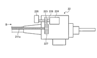
図9は、コネクタの概略的な構成図である。コネクタ24の内部には、超音波振動子211を回転させるためのモータ224が設けられている。ここで、モータ224としては、駆動用のパルス電流に応じて任意の角度に回転させられるステッピングモータや、回転角度や回転数などを検出する検知装置と組み合わせられたサーボモータなどを用いることができる。モータ224には、シャフト228が設けられている。シャフト228には、第1のギア225が取り付けられている。また、フレキシブルシャフト211aの端部には、第2のギア227が取り付けられており、第1のギア225と第2のギア227とが噛み合うことにより、連動して回転するように構成されている。したがって、モータ224を回転させると、シャフト228、第1のギア225、第2のギア227を経由して、フレキシブルシャフト211aに動力を伝達することができる。ここで、本実施例ではギアを2個用いて動力を伝達する構成を記載しているが、これに限られず、必要に応じてギアの数量は増減させてもよい。また、モータ224の動力をフレキシブルシャフト211aに伝達できるものであれば、ギアに限定されず、例えばタイミングベルトなどのような手段を用いてもよい。以上のように、コネクタ24の内部には、超音波振動子211を回転させるためのモータ224と、第1のギア225および第2のギア227などにより構成された伝達機構とを含む回転機構が収容されている。また、シャフト228には、レバー226が取り付けられている。レバー226を手動で回転させることにより、シャフト228が回転し、シャフト228の回転に連動してフレキシブルシャフト211aを介在して超音波振動子211を回転させることができる。
FIG. 9 is a schematic configuration diagram of the connector. A motor 224 for rotating the ultrasonic transducer 211 is provided inside the connector 24. Here, as the motor 224, it is possible to use a stepping motor that is rotated at an arbitrary angle according to a driving pulse current, a servo motor that is combined with a detection device that detects a rotation angle, a rotation number, or the like. .. The motor 224 is provided with a shaft 228. A first gear 225 is attached to the shaft 228. A second gear 227 is attached to the end of the flexible shaft 211a, and the first gear 225 and the second gear 227 mesh with each other so that they rotate in conjunction with each other. .. Therefore, when the motor 224 is rotated, power can be transmitted to the flexible shaft 211a via the shaft 228, the first gear 225, and the second gear 227. Here, in the present embodiment, a configuration is described in which two gears are used to transmit power, but the configuration is not limited to this, and the number of gears may be increased or decreased as necessary. Further, as long as the power of the motor 224 can be transmitted to the flexible shaft 211a, it is not limited to a gear and, for example, a means such as a timing belt may be used. As described above, inside the connector 24, the rotation mechanism including the motor 224 for rotating the ultrasonic transducer 211 and the transmission mechanism configured by the first gear 225, the second gear 227 and the like is provided. It is housed. A lever 226 is attached to the shaft 228. By manually rotating the lever 226, the shaft 228 rotates, and the ultrasonic transducer 211 can be rotated by interposing the flexible shaft 211a in association with the rotation of the shaft 228.
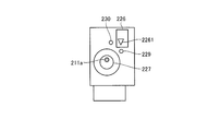
図10は、図9のB矢視図である。図10に示すように、レバー226は、超音波振動子211の回転方向における角度を表示する角度表示部としての指標2261を有する。例えば、指標2261が、第1の目印229の方向に向いているときには、超音波振動子211の向きが挿入部21を被検体の体内に挿入しやすい状態であることを示すものであり、第2の目印230の方向に向いているときには、超音波振動子211の向きは処置具突出口2123bから処置具を突出させても処置具と超音波振動子211とが接触しない状態であることを示すものである。
FIG. 10 is a view on arrow B of FIG. 9. As shown in FIG. 10, the lever 226 has an index 2261 as an angle display unit that displays the angle of the ultrasonic transducer 211 in the rotation direction. For example, when the index 2261 is oriented toward the first mark 229, the orientation of the ultrasonic transducer 211 indicates that the insertion portion 21 is easily inserted into the body of the subject. When facing the direction of the second mark 230, the direction of the ultrasonic transducer 211 indicates that the treatment tool and the ultrasonic transducer 211 are not in contact with each other even when the treatment tool is projected from the treatment tool projecting port 2123b. It is shown.
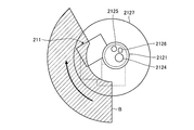
図11及び図12は、超音波内視鏡の先端部を正面から見た様子を表す図である。超音波振動子211が図11に示す角度にあるとき、挿入部21の長手方向に沿って超音波振動子211と第2硬性部2123の処置具突出口2123bにより膨出している部分とが重なるため、挿入部21の長手方向に沿って挿入部21を投影した面積が最小となる。言い換えると、第2硬性部2123の振動子用管路2123cの中心から第2硬質部の外周までの距離が最も大きくなる方向に超音波振動子211の音響レンズが向いた状態となる。超音波振動子211の角度を調整して、挿入部21の長手方向に直交する向きの先端部212の断面積が最も小さくなる向きにすることにより、挿入部21を被検体の体内に挿抜しやすい状態にすることができる。
11 and 12 are diagrams showing a state in which the front end of the ultrasonic endoscope is viewed from the front. When the ultrasonic transducer 211 is at the angle shown in FIG. 11, the ultrasonic transducer 211 and the portion of the second rigid portion 2123 that is bulged by the treatment tool projecting port 2123b overlap along the longitudinal direction of the insertion portion 21. Therefore, the area where the insertion portion 21 is projected along the longitudinal direction of the insertion portion 21 becomes the minimum. In other words, the acoustic lens of the ultrasonic transducer 211 is oriented in the direction in which the distance from the center of the transducer conduit 2123c of the second rigid portion 2123 to the outer periphery of the second rigid portion is maximized. The insertion portion 21 is inserted into and removed from the subject by adjusting the angle of the ultrasonic transducer 211 so that the cross-sectional area of the distal end portion 212 in the direction orthogonal to the longitudinal direction of the insertion portion 21 becomes the smallest. It can be in an easy state.
一方、超音波振動子211が図12に示す角度にあるとき、処置具突出口2123bから突出した処置具が超音波振動子211に接触しない。
On the other hand, when the ultrasonic transducer 211 is at the angle shown in FIG. 12, the treatment instrument protruding from the treatment instrument projecting port 2123b does not contact the ultrasonic transducer 211.
次に、超音波内視鏡2を用いた観察方法について説明する。はじめに、超音波内視鏡2を操作し、バルーン2127が取り付けられた挿入部21を被検体の体内に挿入した状態で、撮像光学系を用いた光学観察画像により病変部の近傍に超音波振動子211を配置する。続いて、この状態のままバルーン給排水管路2123dよりバルーン2127の内部に脱気水などを送液し、バルーン2127を膨張させる。膨張させたバルーン2127を被検体の体壁に押し当てた状態で、超音波観測装置3を操作して超音波振動子211に電気信号を送ることで、超音波振動子211より超音波を発生させる。さらに超音波観測装置3を操作することで、モータ224を駆動する電力を供給する。モータ224を駆動することにより、フレキシブルシャフト211aを通じて超音波振動子211が回転する。
Next, the observation method using the ultrasonic endoscope 2 will be described. First, while operating the ultrasonic endoscope 2 and inserting the insertion portion 21 with the balloon 2127 attached into the body of the subject, ultrasonic vibration is generated near the lesion by an optical observation image using the imaging optical system. The child 211 is arranged. Subsequently, in this state, deaerated water or the like is fed into the balloon 2127 from the balloon water supply/drainage line 2123d to inflate the balloon 2127. While the inflated balloon 2127 is pressed against the body wall of the subject, the ultrasonic observation device 3 is operated to send an electric signal to the ultrasonic transducer 211 to generate ultrasonic waves from the ultrasonic transducer 211. Let Further, by operating the ultrasonic observation device 3, electric power for driving the motor 224 is supplied. By driving the motor 224, the ultrasonic transducer 211 is rotated through the flexible shaft 211a.
図13は、超音波振動子が回転する様子を表す図である。図13に示すように、超音波振動子211は、図11に示す位置から所定の角度Rまで回転する。言い換えると、超音波振動子211は、ある一定の決められた角度Rで揺動することになる。この角度Rとは、30度から180度程度に設定され得る。このようにすることにより、超音波振動子211を圧電素子の配列方向に電子的に走査することに加え、超音波振動子211を支持部2122の軸周りに機械的に走査することになる。機械的な走査については、モータ224を駆動するパルス電流や回転角度などを検出する検知装置の情報と関連付けることで、図13に示すように、角度Rに含まれる3次元的なエコー情報を取得することができる。これらの情報を逐次取得および保存した超音波観測装置3は、これらの情報に基づき3次元の超音波画像を生成することができる。
FIG. 13 is a diagram showing how the ultrasonic transducer rotates. As shown in FIG. 13, the ultrasonic transducer 211 rotates up to a predetermined angle R from the position shown in FIG. In other words, the ultrasonic transducer 211 will oscillate at a certain fixed angle R. The angle R can be set to about 30 to 180 degrees. By doing so, in addition to electronically scanning the ultrasonic transducers 211 in the arrangement direction of the piezoelectric elements, the ultrasonic transducers 211 are mechanically scanned around the axis of the support portion 2122. Regarding the mechanical scanning, the three-dimensional echo information included in the angle R is acquired as shown in FIG. 13 by associating with the information of the detection device that detects the pulse current or the rotation angle that drives the motor 224. can do. The ultrasonic observation apparatus 3 that sequentially acquires and stores these pieces of information can generate a three-dimensional ultrasonic image based on these pieces of information.
なお、超音波内視鏡2は、上述した実施の形態に限られない。モータ等の回転機構を操作部22に設けてもよい。この場合、フレキシブルシャフト211aは、ユニバーサルコード23の内部まで配置する必要がなくなり、短くすることができる。フレキシブルシャフト211aを短くすることにより、モータ224と超音波振動子211との距離を短くすることができるため、回転力の伝達性を向上させることができる。
The ultrasonic endoscope 2 is not limited to the above embodiment. A rotating mechanism such as a motor may be provided in the operation unit 22. In this case, the flexible shaft 211a does not need to be arranged inside the universal cord 23, and can be shortened. By shortening the flexible shaft 211a, the distance between the motor 224 and the ultrasonic transducer 211 can be shortened, so that the transmissibility of the rotational force can be improved.
また、モータ224をコネクタ24に配置し、回転角度などを検出する検知装置を操作部22や先端部212に配置してもよい。このように、検知装置を超音波振動子211に近い位置に配置することで、超音波振動子211の回転角度をより精度良く検出することができる。
Alternatively, the motor 224 may be arranged in the connector 24, and a detection device for detecting a rotation angle or the like may be arranged in the operation section 22 or the tip section 212. As described above, by disposing the detection device at a position close to the ultrasonic transducer 211, the rotation angle of the ultrasonic transducer 211 can be detected more accurately.
また、別の実施例としては、先端部212にモータ等の回転機構を配置することもできる。この場合は、フレキシブルシャフト211aを有しない構成とすることができ、フレキシブルシャフト211aの撓みなどの影響を受けずに、より好適な回転運動を実現することができる。
Further, as another embodiment, a rotation mechanism such as a motor may be arranged at the tip portion 212. In this case, the flexible shaft 211a may not be provided, and more suitable rotational movement can be realized without being affected by the bending of the flexible shaft 211a.
超音波観測装置3は、角度センサが検出した角度を表示装置5に表示させる機能を備えていてもよい。さらに、超音波観測装置3は、挿入部21の長手方向に沿って、該挿入部21を投影した面積が最小となる超音波振動子211の角度を表示装置5に表示させる機能を備えていてもよい。また、超音波観測装置3は、処置具突出口2123bから突出した処置具が超音波振動子211に接触しない超音波振動子211の角度を表示装置5に表示させる機能を備えていてもよい。
The ultrasonic observation device 3 may have a function of displaying the angle detected by the angle sensor on the display device 5. Further, the ultrasonic observation device 3 has a function of displaying the angle of the ultrasonic transducer 211, which has the smallest projected area of the insertion portion 21, along the longitudinal direction of the insertion portion 21 on the display device 5. Good. Further, the ultrasonic observation device 3 may have a function of causing the display device 5 to display the angle of the ultrasonic transducer 211 at which the treatment instrument protruding from the treatment instrument protrusion port 2123b does not contact the ultrasonic transducer 211.
操作者は、任意のタイミングで2次元の超音波画像を観察することも、3次元の超音波画像を観察することもできる。従来の超音波内視鏡で得られる2次元の超音波画像は観察領域も狭く、観察部位を特定する手がかりが少ないが、本発明に係る超音波内視鏡2では、広い範囲を観察することが可能となり、さらに超音波画像を3次元表示で確認することができるため、病変部を把握しやすくなる。
The operator can observe a two-dimensional ultrasonic image or a three-dimensional ultrasonic image at any timing. A two-dimensional ultrasonic image obtained by a conventional ultrasonic endoscope has a narrow observation region and few clues for identifying an observation site. However, the ultrasonic endoscope 2 according to the present invention can observe a wide range. Since it is possible to confirm the ultrasonic image in a three-dimensional display, it is easy to grasp the lesion area.
(変形例)
変形例に係る超音波内視鏡は、第2硬性部に設けられており、挿入部の長手方向と交差する方向を撮像する撮像部を備える。このように、超音波内視鏡は、実施の形態のような直視型に限られず、超音波振動子の基端側に撮像部が位置する斜視型の超音波内視鏡であってもよい。 (Modification)
The ultrasonic endoscope according to the modified example is provided in the second rigid portion, and includes an image capturing section that captures an image in a direction intersecting the longitudinal direction of the insertion section. As described above, the ultrasonic endoscope is not limited to the direct-view type as in the embodiment, and may be a perspective-type ultrasonic endoscope in which the imaging unit is located on the base end side of the ultrasonic transducer. ..
また、超音波内視鏡の第1硬性部には、基端側から挿入された処置具を挿入部の長手方向に沿って突出させる処置具突出口が形成されている。このように、超音波内視鏡は、実施の形態のように超音波振動子の基端側から処置具を突出させてもよいが、超音波振動子の先端側から処置具を突出させてもよい。また、超音波内視鏡は、挿入部21の長手方向に沿って処置具を突出させてもよいが、挿入部21の長手方向と交差する方向に処置具を突出させてもよい。
Also, the first rigid portion of the ultrasonic endoscope is formed with a treatment instrument projecting port for projecting the treatment instrument inserted from the proximal end side along the longitudinal direction of the insertion section. As described above, the ultrasonic endoscope may project the treatment tool from the proximal end side of the ultrasonic transducer as in the embodiment, but the treatment tool may be projected from the distal end side of the ultrasonic transducer. Good. The ultrasonic endoscope may project the treatment tool along the longitudinal direction of the insertion section 21, but may project the treatment tool in a direction intersecting the longitudinal direction of the insertion section 21.
また、上述した実施の形態では、第1硬性部2121が樹脂からなるため、超音波振動子211が故障した際に第1硬性部2121を破壊して超音波振動子211を取り外し、超音波振動子211を修理又は交換することができる。
Further, in the above-described embodiment, since the first rigid portion 2121 is made of resin, when the ultrasonic transducer 211 breaks down, the first rigid portion 2121 is destroyed and the ultrasonic transducer 211 is removed, and ultrasonic vibration is performed. The child 211 can be repaired or replaced.
さらなる効果や変形例は、当業者によって容易に導き出すことができる。よって、本発明のより広範な態様は、以上のように表し、かつ記述した特定の詳細及び代表的な実施の形態に限定されるものではない。従って、添付のクレーム及びその均等物によって定義される総括的な発明の概念の精神又は範囲から逸脱することなく、様々な変更が可能である。
Further effects and modified examples can be easily derived by those skilled in the art. Accordingly, the broader aspects of the present invention are not limited to the specific details and representative embodiments shown and described above. Accordingly, various modifications may be made without departing from the spirit or scope of the general inventive concept as defined by the appended claims and their equivalents.
1 内視鏡システム
2 超音波内視鏡
3 超音波観測装置
4 内視鏡観察装置
5 表示装置
6 光源装置
21 挿入部
22 操作部
23 ユニバーサルコード
24 コネクタ
31 超音波ケーブル
41 ビデオケーブル
61 光ファイバケーブル
211 超音波振動子
211a フレキシブルシャフト
211b 信号線
211c 音響レンズ
211d ハウジング
212 先端部
213 湾曲部
214 可撓管部
221 湾曲ノブ
222 操作部材
223 処置具挿入口
224 モータ
225 第1のギア
226 レバー
227 第2のギア
228 シャフト
229 第1の目印
230 第2の目印
2121 第1硬性部
2121a 第1バンド溝
2121b 凹部
2122 支持部
2122a 凸部
2123 第2硬性部
2123a 第2バンド溝
2123b 処置具突出口
2123c 振動子用管路
2123d バルーン給排水管路
2123e 撮像用信号線管路
2123f ライトガイド用管路
2123g 送水管路
2124 撮像部
2125 照明部
2126 ノズル
2127 バルーン
2127a、2127b バルーンバンド
2261 指標 1Endoscope System 2 Ultrasound Endoscope 3 Ultrasound Observation Device 4 Endoscope Observation Device 5 Display Device 6 Light Source Device 21 Insertion Section 22 Operation Section 23 Universal Cord 24 Connector 31 Ultrasonic Cable 41 Video Cable 61 Optical Fiber Cable 211 Ultrasonic transducer 211a Flexible shaft 211b Signal line 211c Acoustic lens 211d Housing 212 Tip part 213 Curved part 214 Flexible tube part 221 Curved knob 222 Operation member 223 Treatment tool insertion port 224 Motor 225 First gear 226 Lever 227 Second Gear 228 Shaft 229 First mark 230 Second mark 2121 First hard part 2121a First band groove 2121b Recess 2122 Support part 2122a Projection 2123 Second hard part 2123a Second band groove 2123b Treatment tool projecting port 2123c Transducer Pipe line 2123d Balloon water supply/drainage line 2123e Image signal line line 2123f Light guide line 2123g Water supply line 2124 Imaging unit 2125 Illumination unit 2126 Nozzle 2127 Balloon 2127a, 2127b Balloon band 2261 Index
2 超音波内視鏡
3 超音波観測装置
4 内視鏡観察装置
5 表示装置
6 光源装置
21 挿入部
22 操作部
23 ユニバーサルコード
24 コネクタ
31 超音波ケーブル
41 ビデオケーブル
61 光ファイバケーブル
211 超音波振動子
211a フレキシブルシャフト
211b 信号線
211c 音響レンズ
211d ハウジング
212 先端部
213 湾曲部
214 可撓管部
221 湾曲ノブ
222 操作部材
223 処置具挿入口
224 モータ
225 第1のギア
226 レバー
227 第2のギア
228 シャフト
229 第1の目印
230 第2の目印
2121 第1硬性部
2121a 第1バンド溝
2121b 凹部
2122 支持部
2122a 凸部
2123 第2硬性部
2123a 第2バンド溝
2123b 処置具突出口
2123c 振動子用管路
2123d バルーン給排水管路
2123e 撮像用信号線管路
2123f ライトガイド用管路
2123g 送水管路
2124 撮像部
2125 照明部
2126 ノズル
2127 バルーン
2127a、2127b バルーンバンド
2261 指標 1
Claims (20)
- 被検体内に挿入される挿入部の先端に位置する第1硬性部と、
前記第1硬性部の基端側に接続されており、前記挿入部の長手方向に沿って長尺状をなす支持部と、
前記支持部の基端側に接続されている第2硬性部と、
前記支持部に固定されており、前記挿入部の長手方向に沿って複数の圧電素子が配列されてなる超音波振動子と、
前記支持部及び前記超音波振動子を一体的に回転させる回転機構と、
を備える超音波内視鏡。 A first rigid portion located at the tip of the insertion portion to be inserted into the subject;
A support portion that is connected to the proximal end side of the first rigid portion and that is elongated along the longitudinal direction of the insertion portion;
A second rigid portion connected to the base end side of the support portion;
An ultrasonic transducer, which is fixed to the support portion and has a plurality of piezoelectric elements arranged along the longitudinal direction of the insertion portion,
A rotation mechanism that integrally rotates the support portion and the ultrasonic transducer,
An ultrasonic endoscope including. - 前記第1硬性部に設けられており、前記挿入部の長手方向に沿った方向を撮像する撮像部を備える請求項1に記載の超音波内視鏡。 The ultrasonic endoscope according to claim 1, further comprising: an imaging unit that is provided in the first rigid portion and that captures an image in a direction along a longitudinal direction of the insertion portion.
- 前記第2硬性部に設けられており、前記挿入部の長手方向と交差する方向を撮像する撮像部を備える請求項1に記載の超音波内視鏡。 The ultrasonic endoscope according to claim 1, further comprising an imaging unit that is provided in the second rigid portion and that captures an image in a direction intersecting a longitudinal direction of the insertion portion.
- 前記第2硬性部には、基端側から挿入された処置具を前記挿入部の長手方向に沿って突出させる処置具突出口が形成されている請求項1~3のいずれか1つに記載の超音波内視鏡。 The treatment instrument projecting port for projecting a treatment instrument inserted from the proximal end side along the longitudinal direction of the insertion portion is formed in the second rigid portion. Ultrasound endoscopy.
- 前記第1硬性部には、基端側から挿入された処置具を前記挿入部の長手方向に沿って突出させる処置具突出口が形成されている請求項1~3のいずれか1つに記載の超音波内視鏡。 The treatment instrument projecting port for projecting a treatment instrument inserted from the proximal end side along the longitudinal direction of the insertion portion is formed in the first rigid portion. Ultrasound endoscopy.
- 前記第1硬性部及び前記第2硬性部には、バルーンバンドを係止するバルーン溝が形成されている請求項1~5のいずれか1つに記載の超音波内視鏡。 The ultrasonic endoscope according to any one of claims 1 to 5, wherein a balloon groove that locks a balloon band is formed in each of the first hard portion and the second hard portion.
- 前記超音波振動子には、前記回転機構の動力を伝達するフレキシブルシャフトが接続されている請求項1~6のいずれか1つに記載の超音波内視鏡。 The ultrasonic endoscope according to any one of claims 1 to 6, wherein a flexible shaft for transmitting power of the rotating mechanism is connected to the ultrasonic oscillator.
- 前記フレキシブルシャフトの内部には、前記超音波振動子の各圧電素子に接続されている複数の信号線が挿通されている請求項7に記載の超音波内視鏡。 The ultrasonic endoscope according to claim 7, wherein a plurality of signal lines connected to the piezoelectric elements of the ultrasonic transducer are inserted inside the flexible shaft.
- 前記超音波振動子は、前記複数の圧電素子の長手方向が、前記挿入部の長手方向と直交しており、曲面をなして配列されているコンベックス型の超音波振動子である請求項1~8のいずれか1つに記載の超音波内視鏡。 The ultrasonic transducer is a convex type ultrasonic transducer in which the longitudinal directions of the plurality of piezoelectric elements are orthogonal to the longitudinal direction of the insertion portion and are arranged in a curved surface. 8. The ultrasonic endoscope according to any one of 8.
- 前記第1硬性部は、樹脂からなる請求項1~9のいずれか1つに記載の超音波内視鏡。 The ultrasonic endoscope according to any one of claims 1 to 9, wherein the first rigid portion is made of resin.
- 前記回転機構は、前記超音波振動子を回転させるモータである請求項1~10のいずれか1つに記載の超音波内視鏡。 The ultrasonic endoscope according to any one of claims 1 to 10, wherein the rotating mechanism is a motor that rotates the ultrasonic transducer.
- 前記回転機構より先端側に設けられており、前記超音波振動子が回転する方向の角度を検出する角度センサを備える請求項1~11のいずれか1つに記載の超音波内視鏡。 The ultrasonic endoscope according to any one of claims 1 to 11, further comprising an angle sensor that is provided on a tip side of the rotation mechanism and that detects an angle in a direction in which the ultrasonic transducer rotates.
- 前記超音波振動子の回転方向における角度を表示する角度表示部を備える請求項12に記載の超音波内視鏡。 The ultrasonic endoscope according to claim 12, further comprising an angle display unit that displays an angle in the rotation direction of the ultrasonic transducer.
- 前記角度表示部は、前記挿入部の長手方向に沿って、該挿入部を投影した面積が最小となる前記超音波振動子の角度を示す第1の目印を有する請求項13に記載の超音波内視鏡。 The ultrasonic wave according to claim 13, wherein the angle display portion has a first mark that indicates an angle of the ultrasonic transducer having a minimum projected area of the insertion portion along a longitudinal direction of the insertion portion. Endoscope.
- 前記回転機構より先端側に設けられており、前記超音波振動子が回転する方向の角度を検出する角度センサと、
前記超音波振動子が回転する方向の角度を表示する角度表示部と、を備え、
前記角度表示部は、前記処置具突出口から突出した前記処置具が前記超音波振動子に接触しない前記超音波振動子の角度を示す第2の目印を有する請求項4に記載の超音波内視鏡。 An angle sensor that is provided on the tip side of the rotating mechanism and detects an angle in a direction in which the ultrasonic transducer rotates,
An angle display unit that displays the angle of the direction in which the ultrasonic transducer rotates,
The ultrasonic wave according to claim 4, wherein the angle display portion has a second mark indicating an angle of the ultrasonic transducer in which the treatment instrument protruding from the treatment instrument projecting port does not contact the ultrasonic transducer. Endoscope. - 請求項1~15に記載の超音波内視鏡と、
前記超音波内視鏡に電気的なパルス信号を送信し、超音波を照射させるとともに、前記超音波内視鏡が受信した超音波エコーを変換した電気的なエコー信号を受信して、超音波画像を生成する超音波観測装置と、
を備える内視鏡システム。 The ultrasonic endoscope according to any one of claims 1 to 15,
An electric pulse signal is transmitted to the ultrasonic endoscope, and an ultrasonic wave is emitted, and an electric echo signal obtained by converting an ultrasonic echo received by the ultrasonic endoscope is received. An ultrasonic observation device for generating an image,
An endoscope system including. - 前記回転機構より先端側に設けられており、前記超音波振動子が回転する方向の角度を検出する角度センサを備え、
前記超音波観測装置は、前記角度センサが検出した角度に応じて前記超音波画像を合成した3次元画像を生成する請求項16に記載の内視鏡システム。 An angle sensor that is provided on the tip side of the rotation mechanism and detects an angle in a direction in which the ultrasonic transducer rotates,
The endoscope system according to claim 16, wherein the ultrasonic observation device generates a three-dimensional image in which the ultrasonic images are combined according to an angle detected by the angle sensor. - 前記超音波観測装置は、前記角度センサが検出した角度を表示装置に表示させる請求項17に記載の内視鏡システム。 The endoscope system according to claim 17, wherein the ultrasonic observation device causes a display device to display an angle detected by the angle sensor.
- 前記挿入部の長手方向に沿って、該挿入部を投影した面積が最小となる前記超音波振動子の角度を表示装置に表示させる請求項17又は18に記載の内視鏡システム。 The endoscope system according to claim 17 or 18, wherein the display device displays the angle of the ultrasonic transducer having the smallest projected area of the insertion portion along the longitudinal direction of the insertion portion.
- 前記第2硬性部には、基端側から挿入された処置具を前記挿入部の長手方向に沿って突出させる処置具突出口が形成されており、
前記超音波観測装置は、前記処置具突出口から突出した前記処置具が前記超音波振動子に接触しない前記超音波振動子の角度を表示装置に表示させる請求項17~19のいずれか1つに記載の内視鏡システム。 The second rigid portion is formed with a treatment instrument projecting port for projecting the treatment instrument inserted from the proximal end side along the longitudinal direction of the insertion section,
20. The ultrasonic observation device causes a display device to display an angle of the ultrasonic transducer in which the treatment tool protruding from the treatment tool projecting port does not contact the ultrasonic vibrator. The endoscope system described in.
Priority Applications (3)
| Application Number | Priority Date | Filing Date | Title |
|---|---|---|---|
| JP2020567285A JP7184928B2 (en) | 2019-01-22 | 2019-01-22 | Ultrasound endoscope and endoscope system |
| PCT/JP2019/001929 WO2020152791A1 (en) | 2019-01-22 | 2019-01-22 | Ultrasound endoscope and endoscope system |
| US17/376,698 US20210338066A1 (en) | 2019-01-22 | 2021-07-15 | Ultrasound endoscope and endoscope system |
Applications Claiming Priority (1)
| Application Number | Priority Date | Filing Date | Title |
|---|---|---|---|
| PCT/JP2019/001929 WO2020152791A1 (en) | 2019-01-22 | 2019-01-22 | Ultrasound endoscope and endoscope system |
Related Child Applications (1)
| Application Number | Title | Priority Date | Filing Date |
|---|---|---|---|
| US17/376,698 Continuation US20210338066A1 (en) | 2019-01-22 | 2021-07-15 | Ultrasound endoscope and endoscope system |
Publications (1)
| Publication Number | Publication Date |
|---|---|
| WO2020152791A1 true WO2020152791A1 (en) | 2020-07-30 |
Family
ID=71735679
Family Applications (1)
| Application Number | Title | Priority Date | Filing Date |
|---|---|---|---|
| PCT/JP2019/001929 WO2020152791A1 (en) | 2019-01-22 | 2019-01-22 | Ultrasound endoscope and endoscope system |
Country Status (3)
| Country | Link |
|---|---|
| US (1) | US20210338066A1 (en) |
| JP (1) | JP7184928B2 (en) |
| WO (1) | WO2020152791A1 (en) |
Citations (3)
| Publication number | Priority date | Publication date | Assignee | Title |
|---|---|---|---|---|
| JPH078496A (en) * | 1993-06-25 | 1995-01-13 | Toshiba Corp | Ultrasonic diagnostic device |
| JPH07227395A (en) * | 1993-12-24 | 1995-08-29 | Olympus Optical Co Ltd | Ultrasonic diagnostic and curing system |
| JP2010000210A (en) * | 2008-06-20 | 2010-01-07 | Fujinon Corp | Probe |
Family Cites Families (4)
| Publication number | Priority date | Publication date | Assignee | Title |
|---|---|---|---|---|
| US5060632A (en) * | 1989-09-05 | 1991-10-29 | Olympus Optical Co., Ltd. | Endoscope apparatus |
| US5471988A (en) * | 1993-12-24 | 1995-12-05 | Olympus Optical Co., Ltd. | Ultrasonic diagnosis and therapy system in which focusing point of therapeutic ultrasonic wave is locked at predetermined position within observation ultrasonic scanning range |
| IL170404A (en) * | 2004-08-26 | 2012-03-29 | C2Cure Inc | Wireless determination of endoscope orientation |
| US11389164B2 (en) * | 2017-12-28 | 2022-07-19 | Cilag Gmbh International | Method of using reinforced flexible circuits with multiple sensors to optimize performance of radio frequency devices |
-
2019
- 2019-01-22 JP JP2020567285A patent/JP7184928B2/en active Active
- 2019-01-22 WO PCT/JP2019/001929 patent/WO2020152791A1/en active Application Filing
-
2021
- 2021-07-15 US US17/376,698 patent/US20210338066A1/en active Pending
Patent Citations (3)
| Publication number | Priority date | Publication date | Assignee | Title |
|---|---|---|---|---|
| JPH078496A (en) * | 1993-06-25 | 1995-01-13 | Toshiba Corp | Ultrasonic diagnostic device |
| JPH07227395A (en) * | 1993-12-24 | 1995-08-29 | Olympus Optical Co Ltd | Ultrasonic diagnostic and curing system |
| JP2010000210A (en) * | 2008-06-20 | 2010-01-07 | Fujinon Corp | Probe |
Also Published As
| Publication number | Publication date |
|---|---|
| JP7184928B2 (en) | 2022-12-06 |
| JPWO2020152791A1 (en) | 2021-10-14 |
| US20210338066A1 (en) | 2021-11-04 |
Similar Documents
| Publication | Publication Date | Title |
|---|---|---|
| JP4551051B2 (en) | Ultrasonic diagnostic equipment | |
| JP6637609B2 (en) | Ultrasound endoscope and ultrasound endoscope system | |
| US20110282209A1 (en) | Ultrasound observation apparatus and control method of ultrasound observation apparatus | |
| JP6133001B1 (en) | Ultrasonic transducer module and ultrasonic endoscope | |
| WO2020152791A1 (en) | Ultrasound endoscope and endoscope system | |
| JP6197145B2 (en) | Ultrasound endoscope | |
| JP4119530B2 (en) | Endoscope device and position detection catheter inserted into endoscope | |
| JP2001120550A (en) | Intra-body cavity ultrasonic probe system | |
| JPH08126644A (en) | Ultrasonic endoscope | |
| JP2000116655A (en) | Diagnostic device | |
| JP4198130B2 (en) | Ultrasonic diagnostic equipment | |
| JP7249788B2 (en) | Endoscope | |
| JP6697962B2 (en) | Ultrasonic transducer and ultrasonic endoscope | |
| JP7422616B2 (en) | Medical instruments and endoscopes | |
| JP3050085B2 (en) | Ultrasound endoscope | |
| JPH0352286B2 (en) | ||
| JP2020156730A (en) | Ultrasound observation apparatus and ultrasound endoscope system | |
| JP7223871B2 (en) | ultrasound endoscope | |
| JPH08117233A (en) | Ultrasonic endoscope device | |
| WO2023053662A1 (en) | Ultrasonic endoscope system and operating method for ultrasonic endoscope system | |
| JPS6258257B2 (en) | ||
| JP4632748B2 (en) | Capsule medical device | |
| JPH11332867A (en) | Ultrasonic endoscope apparatus | |
| JP2017074231A (en) | Method of manufacturing ultrasonic endoscope and ultrasonic endoscope | |
| JP2017144091A (en) | Endoscope and image guide |
Legal Events
| Date | Code | Title | Description |
|---|---|---|---|
| 121 | Ep: the epo has been informed by wipo that ep was designated in this application |
Ref document number: 19911945 Country of ref document: EP Kind code of ref document: A1 |
|
| ENP | Entry into the national phase |
Ref document number: 2020567285 Country of ref document: JP Kind code of ref document: A |
|
| NENP | Non-entry into the national phase |
Ref country code: DE |
|
| 122 | Ep: pct application non-entry in european phase |
Ref document number: 19911945 Country of ref document: EP Kind code of ref document: A1 |