EP3318863A1 - System and method for testing bonded joints - Google Patents
System and method for testing bonded joints Download PDFInfo
- Publication number
- EP3318863A1 EP3318863A1 EP16382515.1A EP16382515A EP3318863A1 EP 3318863 A1 EP3318863 A1 EP 3318863A1 EP 16382515 A EP16382515 A EP 16382515A EP 3318863 A1 EP3318863 A1 EP 3318863A1
- Authority
- EP
- European Patent Office
- Prior art keywords
- actuator
- swing tool
- swing
- load cell
- horizontal bar
- Prior art date
- Legal status (The legal status is an assumption and is not a legal conclusion. Google has not performed a legal analysis and makes no representation as to the accuracy of the status listed.)
- Granted
Links
Images


Classifications
-
- G—PHYSICS
- G01—MEASURING; TESTING
- G01N—INVESTIGATING OR ANALYSING MATERIALS BY DETERMINING THEIR CHEMICAL OR PHYSICAL PROPERTIES
- G01N3/00—Investigating strength properties of solid materials by application of mechanical stress
- G01N3/08—Investigating strength properties of solid materials by application of mechanical stress by applying steady tensile or compressive forces
-
- G—PHYSICS
- G01—MEASURING; TESTING
- G01N—INVESTIGATING OR ANALYSING MATERIALS BY DETERMINING THEIR CHEMICAL OR PHYSICAL PROPERTIES
- G01N19/00—Investigating materials by mechanical methods
- G01N19/04—Measuring adhesive force between materials, e.g. of sealing tape, of coating
-
- G—PHYSICS
- G01—MEASURING; TESTING
- G01N—INVESTIGATING OR ANALYSING MATERIALS BY DETERMINING THEIR CHEMICAL OR PHYSICAL PROPERTIES
- G01N33/00—Investigating or analysing materials by specific methods not covered by groups G01N1/00 - G01N31/00
- G01N33/0003—Composite materials
-
- G—PHYSICS
- G01—MEASURING; TESTING
- G01N—INVESTIGATING OR ANALYSING MATERIALS BY DETERMINING THEIR CHEMICAL OR PHYSICAL PROPERTIES
- G01N2203/00—Investigating strength properties of solid materials by application of mechanical stress
- G01N2203/0058—Kind of property studied
- G01N2203/0091—Peeling or tearing
-
- G—PHYSICS
- G01—MEASURING; TESTING
- G01N—INVESTIGATING OR ANALYSING MATERIALS BY DETERMINING THEIR CHEMICAL OR PHYSICAL PROPERTIES
- G01N2203/00—Investigating strength properties of solid materials by application of mechanical stress
- G01N2203/02—Details not specific for a particular testing method
- G01N2203/026—Specifications of the specimen
Definitions
- the present invention belongs to the field of structural bonded joints. Particularly, it relates to a test of the fracture toughness of bonded joints.
- the strength of structural bonded joints in aeronautical is testing by bonded tests.
- the tests are manufactured by the same composite materials, the same machines and the same process as the parts that represents.
- G1 c test is a standard test of bonding line stress characterization. This method is carried out through calibrated testing machines in laboratories. This method consists of separating two strips of material which are bonded between them, and register the strength and deformation.
- Drum Peel Test Another method, known as Drum Peel Test, is applied for testing bonded joints. This method is focused on sandwich structures, and it consists of roll the outer face of an element on a drum and the rolled strength and displacement of the drum is recorded.
- the present invention provide a swing tool for testing the fracture toughness of bonded joints, being said tool a simplified tool that overcome the disadvantages of the known methods.
- the present invention provides an alternative solution for the aforementioned problems, by a system for testing bonded joints according to claim 1 and a method for testing bonded joints according to claim 14.
- a system for testing bonded joints according to claim 1 and a method for testing bonded joints according to claim 14.
- preferred embodiments of the invention are defined.
- the invention provides a system for testing bonded joints, the bonded joints comprising:
- the present system simplifies the known test methods, providing a portable and repetitive test which improves robustness and representativeness, and which reduces the complexity of the test and reduces values dispersion.
- the fact that the system is portable allows applying directly said system on a part object of study, reducing lead time of the test.
- the present system allows advantageously controlling the deformation of the second element respect to the first element during the test, thus increase the sensitivity of failures detection.
- the actuator comprises a motor with an axis, the motor being configured to supply power to the actuator. Additionally, the actuator comprises a horizontal bar element configured to move vertically along the axis by the motor.
- the motor allows the movement of the actuator in such a way that supplies power providing the movement of the horizontal bar element along the axis.
- the pressure measuring means is a load cell located in contact with the swing tool and the actuator.
- the pressure measuring means is a load cell located inside the actuator.
- the swing tool comprises a protrusion with means of rotation.
- the protrusion is located on the first cantilevered end of the swing tool, and said means of rotation are configured to allow a rotational movement of the load cell in relation to the swing tool.
- the means of rotation allow the rotational movement of the load cell in relation to the swing tool, in such a way that said means of rotation facilities the movement of the swing tool in relation to the movement of the actuator and the load cell.
- the horizontal bar element comprises a kinematic guide joined to the load cell.
- the kinematic guide is configured to move horizontally along the horizontal bar element continually in contact with the load cell.
- the motor allows the movement of the kinematic guide along the horizontal bar element. Additionally, the motor is responsible for applying a force on the swing tool by the actuator. Both movements allow a correct and accurate positioning of the load cell in relation to the swing tool.
- the horizontal bar element comprises a guiding cavity.
- the swing tool further comprises a second cantilevered end being parallel to the first cantilevered end, and a guiding bar.
- the first and second cantilevered end are linked through the guiding cavity of the horizontal element by the guiding bar, such guiding bar being configured to slide along said guiding cavity.
- the actuator is configured to apply a compression force on the cantilevered end of the swing tool.
- the actuator further comprises at least one beam fixed to the support end of the swing tool and located in contact with the load cell.
- the beam fixed to the support end of the swing tool allows that the force applied by the actuator is appropriately transmitted to the swing tool.
- the horizontal bar element and the at least one beam comprise at least two rotational elements.
- the rotational elements are linked to the load cell, and they are configured to allow a rotational movement of said load cell in relation to the horizontal bar element and the at least the beam.
- the actuator further comprises at least one beam fixed to the support end of the sing tool and fixed to the horizontal bar element by rotational elements.
- the rotational elements are configured to allow a rotational movement of the beam in relation to the horizontal bar element.
- the actuator is configured to apply traction force on the support end of the swing tool.
- the rotational elements are arranged for allowing the movement of the load cell in relation to the beam and the horizontal bar element due to the action of the actuator of applying traction force on the swing tool.
- system further comprises at least a second fixing means configured to fix the actuator to the first element.
- the first fixing means allows keeping fixed the actuator to the first element, in such a way that during the action of applying a force on the swing tool, it is avoided that the actuator moves on the first element.
- the second fixing means allows keeping fixed the support end of the swing tool to the second element, in such a way that during the action of applying a force on the swing tool, thanks to said fixing the second element is detached from the first element.
- the first curved side of the swing tool comprises a radio between 75-500 mm.
- the invention provides a method for testing bonded joints, the bonded joints comprising:
- the resulting force that the pressure measuring means measures is proportional to the force that the actuator applies to the swing tool, only in the case of the relation of forces between the actuator and the swing tool is constant.
- the method further comprises a step of fixing the actuator to the first element by the second fixing means previous to the step c).
- the method further comprises a step of wherein a release film is located in the end side of the bonded joint and joined to the second element, previous to the step a).
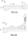
- Figures 1A and 1B show a bonded joint (21) that comprises a first element (1), a second element (2), and an adhesive line (3) located between the first (1) and second (2) element, in such a way that the first (1) and second (2) element are joined together by the adhesive line (3).
- the first element (1) comprises a thickness higher than the thickness of the second element (2).
- the first (1) and second (2) elements comprise between them an end side (11) free of adhesive line (3). This end side (11) free of adhesive line allows a better positioning of a first fixing means (14) (not shown) in order to collaborate with the separation of the second element (2) to the first element (1).
- first element (1) is a real part already fabricated of composite materials
- second element (2) element is a test of composite materials.
- Figure 1B shows the second element (2) substantially separated from the first element (1) due to a force applied on the end side (11).
- the second element (2) is not completely separated to the first element (1) and the adhesive line is divided in a first (3.1) and second (3.2) adhesive line part, thus the first (3.1) and second (3.2) adhesive line part remain bonded to the first (1) and second (2) elements respectively (also shown in figures 2B , 3B and 4 ).
- Figures 2A-5C show a system (20) that comprises a swing tool (4), an actuator (5), and pressure measuring means (6).
- the actuator (5) is configured to apply a force on the swing tool (4) in order to separate the second element (2) with respect to the first element (1).
- the swing tool (4) comprises a first curved side (4.1) configured to be located about the second element (2) and configured to swing on said second element (2).
- the swing tool (4) further comprises a first cantilevered end (4.2) and a support end (4.3).
- the actuator (5) comprises a motor (7) with an axis (8), and said motor (7) is configured to supply power the actuator (5).
- the actuator (5) further comprises a horizontal bar element (9) configured to move vertically along the axis (8) by the motor (7).
- Figures 2A-4 show a release film (12) located in the end side (11) of the bonded joints (21) and joined to the second element (2).
- the first fixing means (14) which is located on the support end (4.3) of the swing tool (4), fixes the swing tool (4) to the second element (2) and the release film (12).
- Said release film (12) is arranged in the end side (11) in order to avoid that the adhesive line (3) flows between the first (1) and second (2) elements.
- the release film (12) is 50 mm lengthwise between the first (1) and second (2) element.
- the system (20) comprises a first fixing means (14) configured to fix the swing tool (4) to the second element (2), and a second fixing means (13) configured to fix the actuator (5) to the first element (1).
- the end side (11) of the bonded joints (21) is provided in order to facilitate the fixing between the swing tool (4) and the second element (2) by said first fixing means (14).
- the fixing means (13, 14) are U-shaped structural elements with an attachment means (19).
- Said U-shaped structural elements (not shown) comprise a first fixing part (13.1, 14.1), a central fixing part (13.2, 14.2) and a second fixing part (13.3, 14.3).
- the second fixing part (13.3, 14.3) is configured to be located under the first element (1) and the second element (2) respectively, and the U-shaped structural elements are fixed to the actuator (5) and to the swing tool (4) by the fastener (19).
- the second fixing part (13.3, 14.3) comprises a rectangular shaped, and the attachment means (19) are fasteners.
- FIGS 2A-3B show a system (20) wherein the pressure measuring means (6) is a load cell located in contact with the swing tool (4) and the actuator (5).
- Figures 2A and 2B show a system (20) wherein the swing tool (4) comprises a protrusion (4.4).
- the protrusion (4.4) comprises means of rotation (4.5) and is located on the first cantilevered end (4.2) of said swing tool (4).
- the means of rotation (4.5) are configured to allow a rotational movement of the load cell (6) in relation to the swing tool (4).
- the horizontal bar element (9) comprises a kinematic guide (10) that is located about the load cell (6), and is configured to move horizontally along the horizontal bar element (9) continually being in contact with the load cell (6).
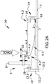
- Figure 2A shows a first position of the system (20) wherein the swing tool (4) is located on the second element (2) of the bonded joint (21), and fixed to said second element (2) by the first fixing means (14). Additionally it is shown the actuator (5) fixed to the first element (1) of the bonded joint (21). In this first position, the actuator has not applied any force to the swing tool (4).
- Figure 2B shows a second position of the system (20) wherein the actuator (5) is applying a compression force on the cantilever end (4.2) of the swing tool (4), thus the swing tool (4) is swung and the support end (4.3) is elevated together with the second element (2) due to the fixing between the second element (2) and the second fixing means (14).
- the application of said compression force on the swing tool (4) produces the separation of the second element (2) to the first element (1), and said compression force is measured by the load cell (6) at the same time.
- the motor (7) operates and generates the movement of the horizontal bar element (9) along the axis (8) (in the direction the arrow "FORCE” indicates), and the movement of the kinematic guide (10) along said horizontal bar element (9), and consequently generated a compression force on the swing tool (4) at the same time that the load cell (6) rotates on the means of rotations (4.5).
- Figure 3A shows a first position of the system (20) wherein the actuator (5) further comprises a beam (15) fixed to the support end (4.3) of the swing tool (4) and located in contact with the load cell (6).
- the horizontal element (9) and the beam (15) comprise two rotational elements (16) linked to the load cell (6).
- the rotational elements (16) are configured to allow a rotational movement of the load cell (6) in relation to the horizontal element (9) and the beam (15).
- the figure 3B shows a second position of the system (20) wherein the actuator (5) is applying a traction force on the support end (4.3) of the swing tool (4), thus the swing tool (4) is swung and the support end (4.3) is elevated together with the second element (2) due to the fixing between the second element (2) and the second fixing means (14).
- the application of said traction force on the swing tool (4) produces the separation of the second element (2) from the first element (1), and said traction force is measured by the load cell (6) at the same time.
- the motor (7) operates and generates the movement of the horizontal bar element (9) along the axis (8) (in the direction the arrow "FORCE” indicates), and the rotational movement of the beam (15) in relation to the load cell (6) by the rotational elements (16), and consequently generated a traction force on the swing tool (4).
- Figures 4-5C show a system (20) wherein the pressure measuring means (6) is a load cell located inside the actuator (5).
- the figure 4 shows a second position of the system (20) wherein the actuator (5) is applying a traction force on the support end (4.3) of the swing tool (4), thus the swing tool (4) is swung and the support end (4.3) is elevated together with the second element (2) due to the fixing between the second element (2) and the second fixing means (14).
- the application of said traction force on the swing tool (4) produces the separation of the second element (2) from the first element (1), and said traction force is measured by the actuator (5) at the same time.
- the motor (7) operates and generates the movement of the horizontal bar element (9) along the axis (8) (in the direction the arrow "FORCE" indicates), and the rotational movement of the beam (15) in relation to the horizontal bar element (9) by the rotational elements (16), and consequently generated a traction force on the swing tool (4).
- Figures 5A-5C show a particular example of the system (20) wherein the horizontal bar element (9) comprises a guiding cavity (9.1), and wherein the swing tool (4) further comprises a second cantilevered end (4.4) and a guiding bar (4.5).
- the second cantilevered end (4.4) is parallel to the first cantilevered end (4.2).
- the first (4.2) and the second (4.5) cantilevered end are linked through the guiding cavity (9.1) of the horizontal element (9) by the guiding bar (4.5).
- the guiding bar (4.5) is configured to slide along the guiding cavity (9.1).
- the motor (7) operates and generates the movement of the horizontal bar element (9) along the axis (8), and the sliding movement of guiding bar (4.5) along the guiding cavity (9.1) of the horizontal bar element (9), and consequently generated a compression force on the swing tool (4).
- Figure 5A shows a system (20) wherein the swing tool (4) comprises a cavity (4.6) located on a second curved side (4.7) of the swing tool (4).
- the second curved side (4.7) is located parallel and opposite to the first curved side (4.1) of the swing tool (4).
- the swing tool (4) comprises said cavity (4.6) in order to allow that the horizontal bar (9) goes into the swing tool (4) across the cavity (4.6) when the actuator (5) applies a compression force to the swing tool (4) (as it shown in figure 5C ).
- Figure 5B shows a system (20) in a first position (the same position shown in figure 5A ) wherein the support end (4.3) of the swing tool (4) is located in contact with the bonded joints (21).
- Figure 5C shows a system (20) in a second position wherein guiding bar (4.5) slides along the guiding cavity (9.1) of the horizontal bar element (9) by the application of a compression force of the actuator on the swing tool (4).
Landscapes
- Chemical & Material Sciences (AREA)
- Health & Medical Sciences (AREA)
- Life Sciences & Earth Sciences (AREA)
- General Health & Medical Sciences (AREA)
- Analytical Chemistry (AREA)
- Biochemistry (AREA)
- Physics & Mathematics (AREA)
- General Physics & Mathematics (AREA)
- Immunology (AREA)
- Pathology (AREA)
- Engineering & Computer Science (AREA)
- Food Science & Technology (AREA)
- Medicinal Chemistry (AREA)
- Investigating Strength Of Materials By Application Of Mechanical Stress (AREA)
Abstract
Description
- The present invention belongs to the field of structural bonded joints. Particularly, it relates to a test of the fracture toughness of bonded joints.
- The strength of structural bonded joints in aeronautical is testing by bonded tests. In the case of composite material parts, the tests are manufactured by the same composite materials, the same machines and the same process as the parts that represents.
- Until know, one possible method for testing bonded joints is the G1 c test, which is a standard test of bonding line stress characterization. This method is carried out through calibrated testing machines in laboratories. This method consists of separating two strips of material which are bonded between them, and register the strength and deformation.
- Another method, known as Drum Peel Test, is applied for testing bonded joints. This method is focused on sandwich structures, and it consists of roll the outer face of an element on a drum and the rolled strength and displacement of the drum is recorded.
- These known methods for testing are carried out through calibrated testing machines in laboratories, and require complex machines and high costs of method, and high times of testing.
- The present invention provide a swing tool for testing the fracture toughness of bonded joints, being said tool a simplified tool that overcome the disadvantages of the known methods.
- The present invention provides an alternative solution for the aforementioned problems, by a system for testing bonded joints according to
claim 1 and a method for testing bonded joints according toclaim 14. In dependent claims, preferred embodiments of the invention are defined. - In a first inventive aspect, the invention provides a system for testing bonded joints, the bonded joints comprising:
- a first element,
- a second element, and
- an adhesive line located between the first and second element,
wherein the first and second element are joined together by the adhesive line, and the first and second element comprise an end side free of adhesive line between both elements, - a swing tool comprising
- a first curved side configured to be located and swing on the second element,
- a first cantilevered end, and
- a support end,
- an actuator,
- pressure measuring means, and
- a first fixing means configured to fix the swing tool to the second element,
- Advantageously, the present system simplifies the known test methods, providing a portable and repetitive test which improves robustness and representativeness, and which reduces the complexity of the test and reduces values dispersion. The fact that the system is portable allows applying directly said system on a part object of study, reducing lead time of the test. Additionally, the present system allows advantageously controlling the deformation of the second element respect to the first element during the test, thus increase the sensitivity of failures detection.
- Throughout this entire document, "separate" and "detach" will be used indistinctly and understood as detaching the second element to the first element.
- In a particular embodiment, the actuator comprises a motor with an axis, the motor being configured to supply power to the actuator. Additionally, the actuator comprises a horizontal bar element configured to move vertically along the axis by the motor.
- Advantageously, the motor allows the movement of the actuator in such a way that supplies power providing the movement of the horizontal bar element along the axis.
- In a particular embodiment, the pressure measuring means is a load cell located in contact with the swing tool and the actuator.
- In another particular embodiment, the pressure measuring means is a load cell located inside the actuator.
- In a particular embodiment, the swing tool comprises a protrusion with means of rotation. The protrusion is located on the first cantilevered end of the swing tool, and said means of rotation are configured to allow a rotational movement of the load cell in relation to the swing tool.
- Advantageously, the means of rotation allow the rotational movement of the load cell in relation to the swing tool, in such a way that said means of rotation facilities the movement of the swing tool in relation to the movement of the actuator and the load cell.
- In a particular embodiment, the horizontal bar element comprises a kinematic guide joined to the load cell. The kinematic guide is configured to move horizontally along the horizontal bar element continually in contact with the load cell.
- Advantageously, the motor allows the movement of the kinematic guide along the horizontal bar element. Additionally, the motor is responsible for applying a force on the swing tool by the actuator. Both movements allow a correct and accurate positioning of the load cell in relation to the swing tool.
- In a particular embodiment, the horizontal bar element comprises a guiding cavity. In a more particular embodiment, the swing tool further comprises a second cantilevered end being parallel to the first cantilevered end, and a guiding bar. In a more particularly embodiment, the first and second cantilevered end are linked through the guiding cavity of the horizontal element by the guiding bar, such guiding bar being configured to slide along said guiding cavity.
- In a particular embodiment, the actuator is configured to apply a compression force on the cantilevered end of the swing tool.
- In another particular embodiment, the actuator further comprises at least one beam fixed to the support end of the swing tool and located in contact with the load cell.
- Advantageously, the beam fixed to the support end of the swing tool allows that the force applied by the actuator is appropriately transmitted to the swing tool.
- In a particular embodiment, the horizontal bar element and the at least one beam comprise at least two rotational elements. The rotational elements are linked to the load cell, and they are configured to allow a rotational movement of said load cell in relation to the horizontal bar element and the at least the beam.
- In another particular embodiment, the actuator further comprises at least one beam fixed to the support end of the sing tool and fixed to the horizontal bar element by rotational elements. The rotational elements are configured to allow a rotational movement of the beam in relation to the horizontal bar element.
- In a particular embodiment, the actuator is configured to apply traction force on the support end of the swing tool.
- Advantageously, the rotational elements are arranged for allowing the movement of the load cell in relation to the beam and the horizontal bar element due to the action of the actuator of applying traction force on the swing tool.
- In a particular embodiment, the system further comprises at least a second fixing means configured to fix the actuator to the first element.
- Advantageously, the first fixing means allows keeping fixed the actuator to the first element, in such a way that during the action of applying a force on the swing tool, it is avoided that the actuator moves on the first element.
- Advantageously, the second fixing means allows keeping fixed the support end of the swing tool to the second element, in such a way that during the action of applying a force on the swing tool, thanks to said fixing the second element is detached from the first element.
- In a particular embodiment, the first curved side of the swing tool comprises a radio between 75-500 mm.
- In a second inventive aspect, the invention provides a method for testing bonded joints, the bonded joints comprising:
- a first element,
- a second element, and
- an adhesive line located between the first and second element,
wherein the first and second element are joined together by the adhesive line, and the first and second element comprise an end side free of adhesive line between both elements, - a) providing a system for testing bonded joints according to the first inventive aspect,
- b) fixing the swing element to the second element by the first fixing means,
- c) operating the actuator, applying a force on the swing tool separating the second element from the first element, and
- d) measuring the force applied on the swing tool by the pressure measuring means.
- The resulting force that the pressure measuring means measures is proportional to the force that the actuator applies to the swing tool, only in the case of the relation of forces between the actuator and the swing tool is constant.
- In a particular embodiment, the method further comprises a step of fixing the actuator to the first element by the second fixing means previous to the step c).
- In a particular embodiment, the method further comprises a step of wherein a release film is located in the end side of the bonded joint and joined to the second element, previous to the step a).
- All the features described in this specification (including the claims, description and drawings) and/or all the steps of the described method can be combined in any combination, with the exception of combinations of such mutually exclusive features and/or steps.
- These and other characteristics and advantages of the invention will become clearly understood in view of the detailed description of the invention which becomes apparent from a preferred embodiment of the invention, given just as an example and not being limited thereto, with reference to the drawings.
- Figures 1A-1B
- These figures show a bonded joint to be tested according to the present invention.
- Figure 2A
- This figure shows a lateral view of the system in a first position according to a particular embodiment of the present invention.
- Figure 2B
- This figure shows a lateral view of the system in a second position, applying force on the swing tool, according to a particular embodiment of the present invention.
- Figure 3A
- This figure shows a lateral view of the system in a first position
- Figure 3B
- according to a particular embodiment of the present invention. This figure shows a lateral view of the system in a second position, applying force on the swing tool, according to a particular embodiment of the present invention.
- Figure 4
- This figure shows a lateral view of the system in a second position, applying force on the swing tool, according to another particular embodiment of the present invention.
- Figure 5A
- This figure shows a perspective view of the system in a first position according to a particular embodiment of the present invention.
- Figures 5B-5C
- These figures show a lateral view of the
Figure 4A in a first and second positioned respectively according to a particular embodiment of the present invention. -
Figures 1A and 1B show a bonded joint (21) that comprises a first element (1), a second element (2), and an adhesive line (3) located between the first (1) and second (2) element, in such a way that the first (1) and second (2) element are joined together by the adhesive line (3). The first element (1) comprises a thickness higher than the thickness of the second element (2). Furthermore, the first (1) and second (2) elements comprise between them an end side (11) free of adhesive line (3). This end side (11) free of adhesive line allows a better positioning of a first fixing means (14) (not shown) in order to collaborate with the separation of the second element (2) to the first element (1). - In a particularly example, the first element (1) is a real part already fabricated of composite materials, and second element (2) element is a test of composite materials.
-
Figure 1B shows the second element (2) substantially separated from the first element (1) due to a force applied on the end side (11). In such a way, the second element (2) is not completely separated to the first element (1) and the adhesive line is divided in a first (3.1) and second (3.2) adhesive line part, thus the first (3.1) and second (3.2) adhesive line part remain bonded to the first (1) and second (2) elements respectively (also shown infigures 2B ,3B and4 ). -
Figures 2A-5C show a system (20) that comprises a swing tool (4), an actuator (5), and pressure measuring means (6). The actuator (5) is configured to apply a force on the swing tool (4) in order to separate the second element (2) with respect to the first element (1). - The swing tool (4) comprises a first curved side (4.1) configured to be located about the second element (2) and configured to swing on said second element (2). The swing tool (4) further comprises a first cantilevered end (4.2) and a support end (4.3).
- The actuator (5) comprises a motor (7) with an axis (8), and said motor (7) is configured to supply power the actuator (5). The actuator (5) further comprises a horizontal bar element (9) configured to move vertically along the axis (8) by the motor (7).
-
Figures 2A-4 show a release film (12) located in the end side (11) of the bonded joints (21) and joined to the second element (2). In this way the first fixing means (14) which is located on the support end (4.3) of the swing tool (4), fixes the swing tool (4) to the second element (2) and the release film (12). Said release film (12) is arranged in the end side (11) in order to avoid that the adhesive line (3) flows between the first (1) and second (2) elements. In a particular example, the release film (12) is 50 mm lengthwise between the first (1) and second (2) element. - Furthermore, it is shown that the system (20) comprises a first fixing means (14) configured to fix the swing tool (4) to the second element (2), and a second fixing means (13) configured to fix the actuator (5) to the first element (1).
- The end side (11) of the bonded joints (21) is provided in order to facilitate the fixing between the swing tool (4) and the second element (2) by said first fixing means (14).
- In a particular example, the fixing means (13, 14) are U-shaped structural elements with an attachment means (19). Said U-shaped structural elements (not shown) comprise a first fixing part (13.1, 14.1), a central fixing part (13.2, 14.2) and a second fixing part (13.3, 14.3). In this particular example the second fixing part (13.3, 14.3) is configured to be located under the first element (1) and the second element (2) respectively, and the U-shaped structural elements are fixed to the actuator (5) and to the swing tool (4) by the fastener (19). In a more particular example, the second fixing part (13.3, 14.3) comprises a rectangular shaped, and the attachment means (19) are fasteners.
-
Figures 2A-3B show a system (20) wherein the pressure measuring means (6) is a load cell located in contact with the swing tool (4) and the actuator (5). -
Figures 2A and2B show a system (20) wherein the swing tool (4) comprises a protrusion (4.4). The protrusion (4.4) comprises means of rotation (4.5) and is located on the first cantilevered end (4.2) of said swing tool (4). The means of rotation (4.5) are configured to allow a rotational movement of the load cell (6) in relation to the swing tool (4). - The horizontal bar element (9) comprises a kinematic guide (10) that is located about the load cell (6), and is configured to move horizontally along the horizontal bar element (9) continually being in contact with the load cell (6).
-
Figure 2A shows a first position of the system (20) wherein the swing tool (4) is located on the second element (2) of the bonded joint (21), and fixed to said second element (2) by the first fixing means (14). Additionally it is shown the actuator (5) fixed to the first element (1) of the bonded joint (21). In this first position, the actuator has not applied any force to the swing tool (4). -
Figure 2B shows a second position of the system (20) wherein the actuator (5) is applying a compression force on the cantilever end (4.2) of the swing tool (4), thus the swing tool (4) is swung and the support end (4.3) is elevated together with the second element (2) due to the fixing between the second element (2) and the second fixing means (14). The application of said compression force on the swing tool (4) produces the separation of the second element (2) to the first element (1), and said compression force is measured by the load cell (6) at the same time. - As it is shown in
figure 2B , the motor (7) operates and generates the movement of the horizontal bar element (9) along the axis (8) (in the direction the arrow "FORCE" indicates), and the movement of the kinematic guide (10) along said horizontal bar element (9), and consequently generated a compression force on the swing tool (4) at the same time that the load cell (6) rotates on the means of rotations (4.5). -
Figure 3A shows a first position of the system (20) wherein the actuator (5) further comprises a beam (15) fixed to the support end (4.3) of the swing tool (4) and located in contact with the load cell (6). - The horizontal element (9) and the beam (15) comprise two rotational elements (16) linked to the load cell (6). The rotational elements (16) are configured to allow a rotational movement of the load cell (6) in relation to the horizontal element (9) and the beam (15).
- The
figure 3B shows a second position of the system (20) wherein the actuator (5) is applying a traction force on the support end (4.3) of the swing tool (4), thus the swing tool (4) is swung and the support end (4.3) is elevated together with the second element (2) due to the fixing between the second element (2) and the second fixing means (14). The application of said traction force on the swing tool (4) produces the separation of the second element (2) from the first element (1), and said traction force is measured by the load cell (6) at the same time. - As it is shown in
figure 3B , the motor (7) operates and generates the movement of the horizontal bar element (9) along the axis (8) (in the direction the arrow "FORCE" indicates), and the rotational movement of the beam (15) in relation to the load cell (6) by the rotational elements (16), and consequently generated a traction force on the swing tool (4). -
Figures 4-5C show a system (20) wherein the pressure measuring means (6) is a load cell located inside the actuator (5). - The
figure 4 shows a second position of the system (20) wherein the actuator (5) is applying a traction force on the support end (4.3) of the swing tool (4), thus the swing tool (4) is swung and the support end (4.3) is elevated together with the second element (2) due to the fixing between the second element (2) and the second fixing means (14). The application of said traction force on the swing tool (4) produces the separation of the second element (2) from the first element (1), and said traction force is measured by the actuator (5) at the same time. - Furthermore, the motor (7) operates and generates the movement of the horizontal bar element (9) along the axis (8) (in the direction the arrow "FORCE" indicates), and the rotational movement of the beam (15) in relation to the horizontal bar element (9) by the rotational elements (16), and consequently generated a traction force on the swing tool (4).
-
Figures 5A-5C show a particular example of the system (20) wherein the horizontal bar element (9) comprises a guiding cavity (9.1), and wherein the swing tool (4) further comprises a second cantilevered end (4.4) and a guiding bar (4.5). The second cantilevered end (4.4) is parallel to the first cantilevered end (4.2). The first (4.2) and the second (4.5) cantilevered end are linked through the guiding cavity (9.1) of the horizontal element (9) by the guiding bar (4.5). The guiding bar (4.5) is configured to slide along the guiding cavity (9.1). - As it is shown in
figures 5A-5C , the motor (7) operates and generates the movement of the horizontal bar element (9) along the axis (8), and the sliding movement of guiding bar (4.5) along the guiding cavity (9.1) of the horizontal bar element (9), and consequently generated a compression force on the swing tool (4). -
Figure 5A shows a system (20) wherein the swing tool (4) comprises a cavity (4.6) located on a second curved side (4.7) of the swing tool (4). The second curved side (4.7) is located parallel and opposite to the first curved side (4.1) of the swing tool (4). The swing tool (4) comprises said cavity (4.6) in order to allow that the horizontal bar (9) goes into the swing tool (4) across the cavity (4.6) when the actuator (5) applies a compression force to the swing tool (4) (as it shown infigure 5C ). -
Figure 5B shows a system (20) in a first position (the same position shown infigure 5A ) wherein the support end (4.3) of the swing tool (4) is located in contact with the bonded joints (21). -
Figure 5C shows a system (20) in a second position wherein guiding bar (4.5) slides along the guiding cavity (9.1) of the horizontal bar element (9) by the application of a compression force of the actuator on the swing tool (4).
Claims (15)
- A system (20) for testing bonded joints (21), the bonded joints (21) comprising:• a first element (1),• a second element (2),and• an adhesive line (3) located between the first (1) and second (2) element, wherein the first (1) and second (2) element are joined together by the adhesive line (3), and the first (1) and second (2) element comprise an end side (11) free of adhesive line (3) between both elements (1, 2),the system (20) comprising:• a swing tool (4) comprisinga first curved side (4.1) configured to be located and swing on the second element (2),a first cantilevered end (4.2),anda support end (4.3),• an actuator (5),• pressure measuring means (6), and• a first fixing means (14) configured to fix the swing tool (4) to the second element (2),wherein the actuator (5) is configured to apply a force to the swing tool (4) and configured to separate the second element (2) with respect to the first element (1), and wherein the pressure measuring means (6) are configured to measure a force applied by the actuator (5) to the swing tool (4).
- A System (20) according to claim 1, wherein the actuator (5) comprises,a motor (7) with an axis (8), the motor (7) being configured to supply power to the actuator (5), anda horizontal bar element (9) configured to move vertically along the axis (8) by the motor (7).
- A System (20) according to claims 1 to 2, wherein the pressure measuring means (6) is a load cell located in contact with the swing tool (4) and the actuator (5).
- A system (20) according to claims 1 to 2, wherein the pressure measuring means (6) is a load cell (6) located inside the actuator (5).
- A System (20) according to claim 3, wherein the swing tool (4) comprises a protrusion (4.4) with means of rotation (4.5), said protrusion (4.4) being located on the first cantilevered end (4.2) of the swing tool (4), and said means of rotation (4.5) being configured to allow a rotational movement of the load cell (6) in relation to the swing tool (4).
- A System (20) according to claim 3, wherein the horizontal bar element (9) comprises a kinematic guide (10) joined to the load cell (6), said kinematic guide (10) being configured to move horizontally along the horizontal bar element (9) continually in contact with the load cell (6).
- A system (20) according to claim 4 whereinthe horizontal bar element (9) comprises a guiding cavity (9.1), andthe swing tool (4) further comprises a second cantilevered end (4.4) beingparallel to the first cantilevered end (4.2), and a guiding bar (4.5), wherein the first (4.2) and second (4.4) cantilevered end are linked through the guiding cavity (9.1) of the horizontal element (9) by the guiding bar (4.5), such guiding bar (4.5) being configured to slide along said guiding cavity (9.1).
- A system (20) according to any of claims 1 to 7, wherein the actuator (5) is configured to apply a compression force on the first cantilevered end (4.2) of the swing tool (4).
- A system (20) according to claim 3, wherein the actuator (5) further comprises,
at least one beam (15) fixed to the support end (4.3) of the swing tool (4) and located in contact with the load cell (6). - A system (20) according to claim 9, wherein the horizontal bar element (9) and the at least one beam (15) comprise at least two rotational elements (16), said rotational elements (16) being linked to the load cell (6) and being configured to allow a rotational movement of the load cell (6) in relation to the horizontal bar element (9) and the at least one beam (15).
- A system (20) according to claims 1, 2 and 4, wherein the actuator (5) further comprises, at least one beam (15) fixed to the support end (4.3) of the swing tool (4) and fixed to the horizontal bar element (9) by rotational elements (16), said rotational elements (16) being configured to allow a rotational movement of the beam (15) in relation to the horizontal bar element (9).
- A system according to any of claims 9 to 11, wherein the actuator (5) is configured to apply traction force on the support end (4.3) of the swing tool (4).
- A system (20) according to any of the previous claims, wherein it further comprises at least a second fixing means (13) configured to fix the actuator (5) to the first element (1).
- A method for testing bonded joints (21), the bonded joints (21) comprising:• a first element (1),• a second element (2),and• an adhesive line (3) located between the first (1) and second (2) element, wherein the first (1) and second (2) element are joined together by the adhesive line (3), and the first (1) and second (2) element comprise an end side (11) free of adhesive line (3) between both elements,the method comprising the steps of:a) providing a system (20) for testing bonded joints (21) according to any of claims 1 - 13,b) fixing the swing element (4) to the second element (2) by the first fixing means (14),c) operating the actuator (5), applying a force on the swing tool (4) separating the second element (2) from the first element (1), andd) measuring the force applied on the swing tool (4) by the pressure measuring means (6).
- A method for testing bonded joints (21) according to claim 14, wherein the method further comprises a step of fixing the actuator (5) to the bonded joint (21) by the second fixing means (13) previous to the step c).
Priority Applications (5)
| Application Number | Priority Date | Filing Date | Title |
|---|---|---|---|
| EP16382515.1A EP3318863B1 (en) | 2016-11-07 | 2016-11-07 | Systems and method for testing bonded joints |
| ES16382515T ES2873924T3 (en) | 2016-11-07 | 2016-11-07 | Systems and method for testing bonded joints |
| US15/804,053 US10408719B2 (en) | 2016-11-07 | 2017-11-06 | System and method for testing bonded joints |
| CA2984783A CA2984783A1 (en) | 2016-11-07 | 2017-11-06 | System and method for testing bonded joints |
| CN201711084612.3A CN108061705A (en) | 2016-11-07 | 2017-11-07 | For testing the system and method for bonding engaging member |
Applications Claiming Priority (1)
| Application Number | Priority Date | Filing Date | Title |
|---|---|---|---|
| EP16382515.1A EP3318863B1 (en) | 2016-11-07 | 2016-11-07 | Systems and method for testing bonded joints |
Publications (2)
| Publication Number | Publication Date |
|---|---|
| EP3318863A1 true EP3318863A1 (en) | 2018-05-09 |
| EP3318863B1 EP3318863B1 (en) | 2021-03-03 |
Family
ID=57394506
Family Applications (1)
| Application Number | Title | Priority Date | Filing Date |
|---|---|---|---|
| EP16382515.1A Not-in-force EP3318863B1 (en) | 2016-11-07 | 2016-11-07 | Systems and method for testing bonded joints |
Country Status (5)
| Country | Link |
|---|---|
| US (1) | US10408719B2 (en) |
| EP (1) | EP3318863B1 (en) |
| CN (1) | CN108061705A (en) |
| CA (1) | CA2984783A1 (en) |
| ES (1) | ES2873924T3 (en) |
Cited By (2)
| Publication number | Priority date | Publication date | Assignee | Title |
|---|---|---|---|---|
| CN110987793A (en) * | 2019-12-17 | 2020-04-10 | 上海市建筑科学研究院有限公司 | In-situ detection device and detection method for structural adhesive bonding performance of hidden frame glass curtain wall |
| WO2022003219A1 (en) * | 2020-07-01 | 2022-01-06 | Universitat De Girona | Device for mode-i fracture toughness testing with controlled loading rate |
Families Citing this family (4)
| Publication number | Priority date | Publication date | Assignee | Title |
|---|---|---|---|---|
| US11268888B1 (en) * | 2017-12-19 | 2022-03-08 | University Of South Florida | Systems and methods for determining concrete strength |
| ES2726912B2 (en) * | 2018-04-09 | 2020-09-25 | Univ Sevilla | TEST EQUIPMENT FOR THE IN SITU DETERMINATION OF TENACITY TO FRACTURE OF GLUED JOINTS |
| CN109030344A (en) * | 2018-05-25 | 2018-12-18 | 中国建筑科学研究院有限公司 | Assembling type enclosing structure piece sealing glue adhesion force on-site detection device |
| US11519881B2 (en) | 2020-03-25 | 2022-12-06 | United States Of America As Represented By The Administrator Of Nasa | Method for the evaluation of adhesive bond strength via swept-frequency ultrasonic phase measurements |
Citations (4)
| Publication number | Priority date | Publication date | Assignee | Title |
|---|---|---|---|---|
| JPS56111439A (en) * | 1980-02-08 | 1981-09-03 | Toyota Central Res & Dev Lab Inc | Peeling strength measuring device |
| US20140326074A1 (en) * | 2013-05-02 | 2014-11-06 | The Boeing Company | Methods and systems for rapidly testing adhesion |
| WO2016001426A1 (en) * | 2014-07-04 | 2016-01-07 | Universite Joseph Fourier | Pure bending mechanical test device, and method for implementing same |
| FR3028313A1 (en) * | 2014-11-06 | 2016-05-13 | Snecma | APPARATUS AND METHOD FOR TESTING |
Family Cites Families (13)
| Publication number | Priority date | Publication date | Assignee | Title |
|---|---|---|---|---|
| FR2572216B1 (en) * | 1984-10-23 | 1987-01-23 | Trt Telecom Radio Electr | METHOD FOR CHECKING BY ADHESIVE OF THE ADHESION OF A LAYER DEPOSITED ON A SURFACE |
| JPH0715438B2 (en) * | 1986-09-27 | 1995-02-22 | 新王子製紙株式会社 | Adhesive strength measuring method and measuring instrument |
| US5894981A (en) * | 1996-11-27 | 1999-04-20 | Orthodyne Electronics Corporation | Integrated pull tester with an ultrasonic wire bonder |
| JP3586112B2 (en) * | 1998-08-27 | 2004-11-10 | 独立行政法人 科学技術振興機構 | Measurement method of thin film adhesion strength using micro scratch tester |
| CN101135625B (en) * | 2006-09-01 | 2010-05-12 | 清华大学 | Measuring method of binding force between carbon nanotube array and substrate |
| CN201852779U (en) * | 2010-03-23 | 2011-06-01 | 深圳市华测检测技术股份有限公司 | A High Temperature Peel Strength Tester for Foil-clad Board |
| WO2012096416A1 (en) * | 2011-01-10 | 2012-07-19 | 한국표준과학연구원 | Electrodynamic complex sensor for nanomaterials |
| CN103868847B (en) * | 2014-03-17 | 2016-09-14 | 深圳市华星光电技术有限公司 | Device is torn in the pressing tested for peeling off rate and method is torn in pressing |
| KR101601403B1 (en) * | 2014-04-01 | 2016-03-09 | 현대자동차주식회사 | The interfacial strength measuring apparatus and method for a gas diffusion layer of fuel cells |
| CN104614314A (en) * | 2015-01-28 | 2015-05-13 | 南京理工大学 | Multifunctional adhesion interface facture tenacity measuring device |
| CN104677822A (en) * | 2015-02-15 | 2015-06-03 | 福建融诚建设工程质量检测有限公司 | Improvement to roller stripping device of aluminum-plastic composite board |
| KR102374162B1 (en) * | 2015-03-02 | 2022-03-11 | 에스케이하이닉스 주식회사 | Method of quantifying adhesion strength of interlayer adhesive element in tensile mode for staked semiconductor device and measurement apparatus for quantifying the same |
| CN105806779B (en) * | 2016-03-21 | 2018-05-22 | 湖北三江航天江河化工科技有限公司 | A kind of interface peel test device and its test method |
-
2016
- 2016-11-07 ES ES16382515T patent/ES2873924T3/en active Active
- 2016-11-07 EP EP16382515.1A patent/EP3318863B1/en not_active Not-in-force
-
2017
- 2017-11-06 US US15/804,053 patent/US10408719B2/en not_active Expired - Fee Related
- 2017-11-06 CA CA2984783A patent/CA2984783A1/en active Pending
- 2017-11-07 CN CN201711084612.3A patent/CN108061705A/en active Pending
Patent Citations (4)
| Publication number | Priority date | Publication date | Assignee | Title |
|---|---|---|---|---|
| JPS56111439A (en) * | 1980-02-08 | 1981-09-03 | Toyota Central Res & Dev Lab Inc | Peeling strength measuring device |
| US20140326074A1 (en) * | 2013-05-02 | 2014-11-06 | The Boeing Company | Methods and systems for rapidly testing adhesion |
| WO2016001426A1 (en) * | 2014-07-04 | 2016-01-07 | Universite Joseph Fourier | Pure bending mechanical test device, and method for implementing same |
| FR3028313A1 (en) * | 2014-11-06 | 2016-05-13 | Snecma | APPARATUS AND METHOD FOR TESTING |
Cited By (3)
| Publication number | Priority date | Publication date | Assignee | Title |
|---|---|---|---|---|
| CN110987793A (en) * | 2019-12-17 | 2020-04-10 | 上海市建筑科学研究院有限公司 | In-situ detection device and detection method for structural adhesive bonding performance of hidden frame glass curtain wall |
| WO2022003219A1 (en) * | 2020-07-01 | 2022-01-06 | Universitat De Girona | Device for mode-i fracture toughness testing with controlled loading rate |
| ES2890198A1 (en) * | 2020-07-01 | 2022-01-17 | Univ Girona | DEVICE FOR FRACTURE TOUGHNESS TESTING IN I-MODE WITH CONTROLLED LOAD SPEED |
Also Published As
| Publication number | Publication date |
|---|---|
| CN108061705A (en) | 2018-05-22 |
| US20180128724A1 (en) | 2018-05-10 |
| CA2984783A1 (en) | 2018-05-07 |
| EP3318863B1 (en) | 2021-03-03 |
| ES2873924T3 (en) | 2021-11-04 |
| US10408719B2 (en) | 2019-09-10 |
Similar Documents
| Publication | Publication Date | Title |
|---|---|---|
| US10408719B2 (en) | System and method for testing bonded joints | |
| US8297130B2 (en) | Microtesting rig with variable compliance loading fibers for measuring mechanical properties of small specimens | |
| US20210372896A1 (en) | Method and means for testing the strength of a bonding between two specimen elements | |
| CN105593658B (en) | Precise Force Apparatus for Force Sensor Calibration | |
| JP6326676B2 (en) | Cartridge for bond tester including bond tester and a plurality of test tools | |
| CN103487315A (en) | Testing device for mechanical property of material | |
| US9958365B2 (en) | Biaxial measuring device and method for determining normal and shear stress-correlated material parameters | |
| KR101737817B1 (en) | Nano material testing apparatus and method for testing material using the same | |
| JPH0339627B2 (en) | ||
| CN101779115A (en) | Peel test device, method for evaluating impact peel property of adhesive tape, adhesive tape, and mobile device | |
| US5741976A (en) | Apparatus for the single-axis examination of micro-tension samples | |
| EP2827124A1 (en) | Apparatus, system and method for compression testing of test specimens | |
| CN211668941U (en) | Double-test-piece adhesive shear test fixture | |
| US7677110B2 (en) | Method and apparatus for measuring the elasticity of materials for lining vehicle components | |
| Kang et al. | A novel method for in situ uniaxial tests at the micro/nano scale—Part I: Theory | |
| JP2006242645A (en) | Jig for in-plane shear test of sheet material and in-plane shear test machine | |
| KR100940700B1 (en) | Grip device for bonding material test | |
| CN206945297U (en) | Measuring mechanism for arrangements for automotive doors | |
| JP3723681B2 (en) | Micromaterial testing equipment | |
| US8919206B2 (en) | Method of testing seal lip bond strength to metal substrate and apparatus therefor | |
| US7131340B2 (en) | Device for low-vibration force measurement in rapid dynamic tensile experiments on material samples | |
| CN220170842U (en) | Adhesive viscosity test equipment | |
| Marzi et al. | 3D optical displacement measurements on dynamically loaded adhesively bonded T-peel specimens | |
| CN223870510U (en) | Paint bonding strength testing device | |
| CN208953428U (en) | A kind of film adhesion test machine |
Legal Events
| Date | Code | Title | Description |
|---|---|---|---|
| PUAI | Public reference made under article 153(3) epc to a published international application that has entered the european phase |
Free format text: ORIGINAL CODE: 0009012 |
|
| STAA | Information on the status of an ep patent application or granted ep patent |
Free format text: STATUS: THE APPLICATION HAS BEEN PUBLISHED |
|
| AK | Designated contracting states |
Kind code of ref document: A1 Designated state(s): AL AT BE BG CH CY CZ DE DK EE ES FI FR GB GR HR HU IE IS IT LI LT LU LV MC MK MT NL NO PL PT RO RS SE SI SK SM TR |
|
| AX | Request for extension of the european patent |
Extension state: BA ME |
|
| STAA | Information on the status of an ep patent application or granted ep patent |
Free format text: STATUS: REQUEST FOR EXAMINATION WAS MADE |
|
| 17P | Request for examination filed |
Effective date: 20181106 |
|
| RBV | Designated contracting states (corrected) |
Designated state(s): AL AT BE BG CH CY CZ DE DK EE ES FI FR GB GR HR HU IE IS IT LI LT LU LV MC MK MT NL NO PL PT RO RS SE SI SK SM TR |
|
| GRAP | Despatch of communication of intention to grant a patent |
Free format text: ORIGINAL CODE: EPIDOSNIGR1 |
|
| STAA | Information on the status of an ep patent application or granted ep patent |
Free format text: STATUS: GRANT OF PATENT IS INTENDED |
|
| INTG | Intention to grant announced |
Effective date: 20201030 |
|
| GRAS | Grant fee paid |
Free format text: ORIGINAL CODE: EPIDOSNIGR3 |
|
| GRAA | (expected) grant |
Free format text: ORIGINAL CODE: 0009210 |
|
| STAA | Information on the status of an ep patent application or granted ep patent |
Free format text: STATUS: THE PATENT HAS BEEN GRANTED |
|
| AK | Designated contracting states |
Kind code of ref document: B1 Designated state(s): AL AT BE BG CH CY CZ DE DK EE ES FI FR GB GR HR HU IE IS IT LI LT LU LV MC MK MT NL NO PL PT RO RS SE SI SK SM TR |
|
| REG | Reference to a national code |
Ref country code: GB Ref legal event code: FG4D |
|
| REG | Reference to a national code |
Ref country code: AT Ref legal event code: REF Ref document number: 1367721 Country of ref document: AT Kind code of ref document: T Effective date: 20210315 Ref country code: CH Ref legal event code: EP |
|
| REG | Reference to a national code |
Ref country code: DE Ref legal event code: R096 Ref document number: 602016053502 Country of ref document: DE |
|
| REG | Reference to a national code |
Ref country code: IE Ref legal event code: FG4D |
|
| REG | Reference to a national code |
Ref country code: LT Ref legal event code: MG9D |
|
| PG25 | Lapsed in a contracting state [announced via postgrant information from national office to epo] |
Ref country code: NO Free format text: LAPSE BECAUSE OF FAILURE TO SUBMIT A TRANSLATION OF THE DESCRIPTION OR TO PAY THE FEE WITHIN THE PRESCRIBED TIME-LIMIT Effective date: 20210603 Ref country code: HR Free format text: LAPSE BECAUSE OF FAILURE TO SUBMIT A TRANSLATION OF THE DESCRIPTION OR TO PAY THE FEE WITHIN THE PRESCRIBED TIME-LIMIT Effective date: 20210303 Ref country code: FI Free format text: LAPSE BECAUSE OF FAILURE TO SUBMIT A TRANSLATION OF THE DESCRIPTION OR TO PAY THE FEE WITHIN THE PRESCRIBED TIME-LIMIT Effective date: 20210303 Ref country code: GR Free format text: LAPSE BECAUSE OF FAILURE TO SUBMIT A TRANSLATION OF THE DESCRIPTION OR TO PAY THE FEE WITHIN THE PRESCRIBED TIME-LIMIT Effective date: 20210604 Ref country code: BG Free format text: LAPSE BECAUSE OF FAILURE TO SUBMIT A TRANSLATION OF THE DESCRIPTION OR TO PAY THE FEE WITHIN THE PRESCRIBED TIME-LIMIT Effective date: 20210603 Ref country code: LT Free format text: LAPSE BECAUSE OF FAILURE TO SUBMIT A TRANSLATION OF THE DESCRIPTION OR TO PAY THE FEE WITHIN THE PRESCRIBED TIME-LIMIT Effective date: 20210303 |
|
| REG | Reference to a national code |
Ref country code: NL Ref legal event code: MP Effective date: 20210303 |
|
| REG | Reference to a national code |
Ref country code: AT Ref legal event code: MK05 Ref document number: 1367721 Country of ref document: AT Kind code of ref document: T Effective date: 20210303 |
|
| PG25 | Lapsed in a contracting state [announced via postgrant information from national office to epo] |
Ref country code: SE Free format text: LAPSE BECAUSE OF FAILURE TO SUBMIT A TRANSLATION OF THE DESCRIPTION OR TO PAY THE FEE WITHIN THE PRESCRIBED TIME-LIMIT Effective date: 20210303 Ref country code: RS Free format text: LAPSE BECAUSE OF FAILURE TO SUBMIT A TRANSLATION OF THE DESCRIPTION OR TO PAY THE FEE WITHIN THE PRESCRIBED TIME-LIMIT Effective date: 20210303 Ref country code: LV Free format text: LAPSE BECAUSE OF FAILURE TO SUBMIT A TRANSLATION OF THE DESCRIPTION OR TO PAY THE FEE WITHIN THE PRESCRIBED TIME-LIMIT Effective date: 20210303 Ref country code: PL Free format text: LAPSE BECAUSE OF FAILURE TO SUBMIT A TRANSLATION OF THE DESCRIPTION OR TO PAY THE FEE WITHIN THE PRESCRIBED TIME-LIMIT Effective date: 20210303 |
|
| PG25 | Lapsed in a contracting state [announced via postgrant information from national office to epo] |
Ref country code: NL Free format text: LAPSE BECAUSE OF FAILURE TO SUBMIT A TRANSLATION OF THE DESCRIPTION OR TO PAY THE FEE WITHIN THE PRESCRIBED TIME-LIMIT Effective date: 20210303 |
|
| PG25 | Lapsed in a contracting state [announced via postgrant information from national office to epo] |
Ref country code: SM Free format text: LAPSE BECAUSE OF FAILURE TO SUBMIT A TRANSLATION OF THE DESCRIPTION OR TO PAY THE FEE WITHIN THE PRESCRIBED TIME-LIMIT Effective date: 20210303 Ref country code: AT Free format text: LAPSE BECAUSE OF FAILURE TO SUBMIT A TRANSLATION OF THE DESCRIPTION OR TO PAY THE FEE WITHIN THE PRESCRIBED TIME-LIMIT Effective date: 20210303 Ref country code: CZ Free format text: LAPSE BECAUSE OF FAILURE TO SUBMIT A TRANSLATION OF THE DESCRIPTION OR TO PAY THE FEE WITHIN THE PRESCRIBED TIME-LIMIT Effective date: 20210303 Ref country code: EE Free format text: LAPSE BECAUSE OF FAILURE TO SUBMIT A TRANSLATION OF THE DESCRIPTION OR TO PAY THE FEE WITHIN THE PRESCRIBED TIME-LIMIT Effective date: 20210303 |
|
| PG25 | Lapsed in a contracting state [announced via postgrant information from national office to epo] |
Ref country code: IS Free format text: LAPSE BECAUSE OF FAILURE TO SUBMIT A TRANSLATION OF THE DESCRIPTION OR TO PAY THE FEE WITHIN THE PRESCRIBED TIME-LIMIT Effective date: 20210703 Ref country code: PT Free format text: LAPSE BECAUSE OF FAILURE TO SUBMIT A TRANSLATION OF THE DESCRIPTION OR TO PAY THE FEE WITHIN THE PRESCRIBED TIME-LIMIT Effective date: 20210705 Ref country code: SK Free format text: LAPSE BECAUSE OF FAILURE TO SUBMIT A TRANSLATION OF THE DESCRIPTION OR TO PAY THE FEE WITHIN THE PRESCRIBED TIME-LIMIT Effective date: 20210303 Ref country code: RO Free format text: LAPSE BECAUSE OF FAILURE TO SUBMIT A TRANSLATION OF THE DESCRIPTION OR TO PAY THE FEE WITHIN THE PRESCRIBED TIME-LIMIT Effective date: 20210303 |
|
| REG | Reference to a national code |
Ref country code: DE Ref legal event code: R097 Ref document number: 602016053502 Country of ref document: DE |
|
| PLBE | No opposition filed within time limit |
Free format text: ORIGINAL CODE: 0009261 |
|
| STAA | Information on the status of an ep patent application or granted ep patent |
Free format text: STATUS: NO OPPOSITION FILED WITHIN TIME LIMIT |
|
| PG25 | Lapsed in a contracting state [announced via postgrant information from national office to epo] |
Ref country code: AL Free format text: LAPSE BECAUSE OF FAILURE TO SUBMIT A TRANSLATION OF THE DESCRIPTION OR TO PAY THE FEE WITHIN THE PRESCRIBED TIME-LIMIT Effective date: 20210303 Ref country code: DK Free format text: LAPSE BECAUSE OF FAILURE TO SUBMIT A TRANSLATION OF THE DESCRIPTION OR TO PAY THE FEE WITHIN THE PRESCRIBED TIME-LIMIT Effective date: 20210303 |
|
| 26N | No opposition filed |
Effective date: 20211206 |
|
| PG25 | Lapsed in a contracting state [announced via postgrant information from national office to epo] |
Ref country code: SI Free format text: LAPSE BECAUSE OF FAILURE TO SUBMIT A TRANSLATION OF THE DESCRIPTION OR TO PAY THE FEE WITHIN THE PRESCRIBED TIME-LIMIT Effective date: 20210303 |
|
| PG25 | Lapsed in a contracting state [announced via postgrant information from national office to epo] |
Ref country code: IT Free format text: LAPSE BECAUSE OF FAILURE TO SUBMIT A TRANSLATION OF THE DESCRIPTION OR TO PAY THE FEE WITHIN THE PRESCRIBED TIME-LIMIT Effective date: 20210303 |
|
| PG25 | Lapsed in a contracting state [announced via postgrant information from national office to epo] |
Ref country code: IS Free format text: LAPSE BECAUSE OF FAILURE TO SUBMIT A TRANSLATION OF THE DESCRIPTION OR TO PAY THE FEE WITHIN THE PRESCRIBED TIME-LIMIT Effective date: 20210703 |
|
| PG25 | Lapsed in a contracting state [announced via postgrant information from national office to epo] |
Ref country code: MC Free format text: LAPSE BECAUSE OF FAILURE TO SUBMIT A TRANSLATION OF THE DESCRIPTION OR TO PAY THE FEE WITHIN THE PRESCRIBED TIME-LIMIT Effective date: 20210303 |
|
| REG | Reference to a national code |
Ref country code: CH Ref legal event code: PL |
|
| PG25 | Lapsed in a contracting state [announced via postgrant information from national office to epo] |
Ref country code: LU Free format text: LAPSE BECAUSE OF NON-PAYMENT OF DUE FEES Effective date: 20211107 Ref country code: BE Free format text: LAPSE BECAUSE OF NON-PAYMENT OF DUE FEES Effective date: 20211130 |
|
| REG | Reference to a national code |
Ref country code: BE Ref legal event code: MM Effective date: 20211130 |
|
| PG25 | Lapsed in a contracting state [announced via postgrant information from national office to epo] |
Ref country code: LI Free format text: LAPSE BECAUSE OF NON-PAYMENT OF DUE FEES Effective date: 20211130 Ref country code: CH Free format text: LAPSE BECAUSE OF NON-PAYMENT OF DUE FEES Effective date: 20211130 |
|
| PG25 | Lapsed in a contracting state [announced via postgrant information from national office to epo] |
Ref country code: IE Free format text: LAPSE BECAUSE OF NON-PAYMENT OF DUE FEES Effective date: 20211107 |
|
| PGFP | Annual fee paid to national office [announced via postgrant information from national office to epo] |
Ref country code: GB Payment date: 20221125 Year of fee payment: 7 Ref country code: FR Payment date: 20221129 Year of fee payment: 7 Ref country code: DE Payment date: 20221123 Year of fee payment: 7 |
|
| PGFP | Annual fee paid to national office [announced via postgrant information from national office to epo] |
Ref country code: ES Payment date: 20230125 Year of fee payment: 7 |
|
| PG25 | Lapsed in a contracting state [announced via postgrant information from national office to epo] |
Ref country code: HU Free format text: LAPSE BECAUSE OF FAILURE TO SUBMIT A TRANSLATION OF THE DESCRIPTION OR TO PAY THE FEE WITHIN THE PRESCRIBED TIME-LIMIT; INVALID AB INITIO Effective date: 20161107 |
|
| PG25 | Lapsed in a contracting state [announced via postgrant information from national office to epo] |
Ref country code: CY Free format text: LAPSE BECAUSE OF FAILURE TO SUBMIT A TRANSLATION OF THE DESCRIPTION OR TO PAY THE FEE WITHIN THE PRESCRIBED TIME-LIMIT Effective date: 20210303 |
|
| PG25 | Lapsed in a contracting state [announced via postgrant information from national office to epo] |
Ref country code: MK Free format text: LAPSE BECAUSE OF FAILURE TO SUBMIT A TRANSLATION OF THE DESCRIPTION OR TO PAY THE FEE WITHIN THE PRESCRIBED TIME-LIMIT Effective date: 20210303 |
|
| REG | Reference to a national code |
Ref country code: DE Ref legal event code: R119 Ref document number: 602016053502 Country of ref document: DE |
|
| PG25 | Lapsed in a contracting state [announced via postgrant information from national office to epo] |
Ref country code: TR Free format text: LAPSE BECAUSE OF FAILURE TO SUBMIT A TRANSLATION OF THE DESCRIPTION OR TO PAY THE FEE WITHIN THE PRESCRIBED TIME-LIMIT Effective date: 20210303 |
|
| GBPC | Gb: european patent ceased through non-payment of renewal fee |
Effective date: 20231107 |
|
| PG25 | Lapsed in a contracting state [announced via postgrant information from national office to epo] |
Ref country code: MT Free format text: LAPSE BECAUSE OF FAILURE TO SUBMIT A TRANSLATION OF THE DESCRIPTION OR TO PAY THE FEE WITHIN THE PRESCRIBED TIME-LIMIT Effective date: 20210303 |
|
| PG25 | Lapsed in a contracting state [announced via postgrant information from national office to epo] |
Ref country code: DE Free format text: LAPSE BECAUSE OF NON-PAYMENT OF DUE FEES Effective date: 20240601 |
|
| PG25 | Lapsed in a contracting state [announced via postgrant information from national office to epo] |
Ref country code: GB Free format text: LAPSE BECAUSE OF NON-PAYMENT OF DUE FEES Effective date: 20231107 |
|
| PG25 | Lapsed in a contracting state [announced via postgrant information from national office to epo] |
Ref country code: FR Free format text: LAPSE BECAUSE OF NON-PAYMENT OF DUE FEES Effective date: 20231130 |
|
| PG25 | Lapsed in a contracting state [announced via postgrant information from national office to epo] |
Ref country code: GB Free format text: LAPSE BECAUSE OF NON-PAYMENT OF DUE FEES Effective date: 20231107 Ref country code: FR Free format text: LAPSE BECAUSE OF NON-PAYMENT OF DUE FEES Effective date: 20231130 Ref country code: DE Free format text: LAPSE BECAUSE OF NON-PAYMENT OF DUE FEES Effective date: 20240601 |
|
| REG | Reference to a national code |
Ref country code: ES Ref legal event code: FD2A Effective date: 20250102 |
|
| PG25 | Lapsed in a contracting state [announced via postgrant information from national office to epo] |
Ref country code: ES Free format text: LAPSE BECAUSE OF NON-PAYMENT OF DUE FEES Effective date: 20231108 |
|
| PG25 | Lapsed in a contracting state [announced via postgrant information from national office to epo] |
Ref country code: ES Free format text: LAPSE BECAUSE OF NON-PAYMENT OF DUE FEES Effective date: 20231108 |