EP3318823A1 - Refrigeration cycle system - Google Patents
Refrigeration cycle system Download PDFInfo
- Publication number
- EP3318823A1 EP3318823A1 EP15897141.6A EP15897141A EP3318823A1 EP 3318823 A1 EP3318823 A1 EP 3318823A1 EP 15897141 A EP15897141 A EP 15897141A EP 3318823 A1 EP3318823 A1 EP 3318823A1
- Authority
- EP
- European Patent Office
- Prior art keywords
- refrigerant
- refrigeration cycle
- indoor
- leakage
- indoor units
- Prior art date
- Legal status (The legal status is an assumption and is not a legal conclusion. Google has not performed a legal analysis and makes no representation as to the accuracy of the status listed.)
- Granted
Links
- 238000005057 refrigeration Methods 0.000 title claims abstract description 184
- 239000003507 refrigerant Substances 0.000 claims abstract description 287
- 238000001514 detection method Methods 0.000 claims abstract description 81
- 238000010586 diagram Methods 0.000 description 24
- 238000012986 modification Methods 0.000 description 10
- 230000004048 modification Effects 0.000 description 10
- 238000013019 agitation Methods 0.000 description 9
- 238000004378 air conditioning Methods 0.000 description 7
- 238000004891 communication Methods 0.000 description 4
- 230000007423 decrease Effects 0.000 description 3
- 230000000694 effects Effects 0.000 description 3
- 239000007788 liquid Substances 0.000 description 2
- 230000005856 abnormality Effects 0.000 description 1
- 238000001816 cooling Methods 0.000 description 1
- 238000007791 dehumidification Methods 0.000 description 1
- 230000006870 function Effects 0.000 description 1
- 238000010438 heat treatment Methods 0.000 description 1
- 230000002401 inhibitory effect Effects 0.000 description 1
- 238000009434 installation Methods 0.000 description 1
- 239000004973 liquid crystal related substance Substances 0.000 description 1
- 238000012423 maintenance Methods 0.000 description 1
Images


Classifications
-
- F—MECHANICAL ENGINEERING; LIGHTING; HEATING; WEAPONS; BLASTING
- F24—HEATING; RANGES; VENTILATING
- F24F—AIR-CONDITIONING; AIR-HUMIDIFICATION; VENTILATION; USE OF AIR CURRENTS FOR SCREENING
- F24F11/00—Control or safety arrangements
- F24F11/30—Control or safety arrangements for purposes related to the operation of the system, e.g. for safety or monitoring
- F24F11/32—Responding to malfunctions or emergencies
- F24F11/36—Responding to malfunctions or emergencies to leakage of heat-exchange fluid
-
- F—MECHANICAL ENGINEERING; LIGHTING; HEATING; WEAPONS; BLASTING
- F24—HEATING; RANGES; VENTILATING
- F24F—AIR-CONDITIONING; AIR-HUMIDIFICATION; VENTILATION; USE OF AIR CURRENTS FOR SCREENING
- F24F11/00—Control or safety arrangements
- F24F11/70—Control systems characterised by their outputs; Constructional details thereof
- F24F11/72—Control systems characterised by their outputs; Constructional details thereof for controlling the supply of treated air, e.g. its pressure
- F24F11/74—Control systems characterised by their outputs; Constructional details thereof for controlling the supply of treated air, e.g. its pressure for controlling air flow rate or air velocity
- F24F11/745—Control systems characterised by their outputs; Constructional details thereof for controlling the supply of treated air, e.g. its pressure for controlling air flow rate or air velocity the air flow rate increasing with an increase of air-current or wind pressure
-
- F—MECHANICAL ENGINEERING; LIGHTING; HEATING; WEAPONS; BLASTING
- F24—HEATING; RANGES; VENTILATING
- F24F—AIR-CONDITIONING; AIR-HUMIDIFICATION; VENTILATION; USE OF AIR CURRENTS FOR SCREENING
- F24F11/00—Control or safety arrangements
- F24F11/70—Control systems characterised by their outputs; Constructional details thereof
- F24F11/72—Control systems characterised by their outputs; Constructional details thereof for controlling the supply of treated air, e.g. its pressure
- F24F11/79—Control systems characterised by their outputs; Constructional details thereof for controlling the supply of treated air, e.g. its pressure for controlling the direction of the supplied air
-
- F—MECHANICAL ENGINEERING; LIGHTING; HEATING; WEAPONS; BLASTING
- F24—HEATING; RANGES; VENTILATING
- F24F—AIR-CONDITIONING; AIR-HUMIDIFICATION; VENTILATION; USE OF AIR CURRENTS FOR SCREENING
- F24F11/00—Control or safety arrangements
- F24F11/70—Control systems characterised by their outputs; Constructional details thereof
- F24F11/80—Control systems characterised by their outputs; Constructional details thereof for controlling the temperature of the supplied air
- F24F11/83—Control systems characterised by their outputs; Constructional details thereof for controlling the temperature of the supplied air by controlling the supply of heat-exchange fluids to heat-exchangers
- F24F11/84—Control systems characterised by their outputs; Constructional details thereof for controlling the temperature of the supplied air by controlling the supply of heat-exchange fluids to heat-exchangers using valves
-
- F—MECHANICAL ENGINEERING; LIGHTING; HEATING; WEAPONS; BLASTING
- F25—REFRIGERATION OR COOLING; COMBINED HEATING AND REFRIGERATION SYSTEMS; HEAT PUMP SYSTEMS; MANUFACTURE OR STORAGE OF ICE; LIQUEFACTION SOLIDIFICATION OF GASES
- F25B—REFRIGERATION MACHINES, PLANTS OR SYSTEMS; COMBINED HEATING AND REFRIGERATION SYSTEMS; HEAT PUMP SYSTEMS
- F25B2500/00—Problems to be solved
- F25B2500/22—Preventing, detecting or repairing leaks of refrigeration fluids
- F25B2500/222—Detecting refrigerant leaks
Definitions
- the present invention relates to a refrigeration cycle system including a plurality of indoor units and a plurality of refrigerant leakage detection devices.
- Patent Literature 1 An air-conditioning apparatus including a refrigerant leakage sensor has been known (see, for example, Patent Literature 1).
- a compressor and a fan motor are stopped, and a refrigerant circuit is shut off by a solenoid shutoff valve, thereby inhibiting the leakage of the refrigerant.
- Patent Literature 1 Japanese Unexamined Patent Application Publication No. 10-281569
- the concentration of the refrigerant that has leaked may locally increase in the vicinity of the leakage location of the refrigerant.
- the present invention has been made in view of the above-described problem, and it is an object of the present invention to provide a refrigeration cycle system that inhibits the concentration of refrigerant that has leaked, from locally increasing, when the refrigerant has leaked.
- a refrigeration cycle system includes a plurality of indoor units installed in an indoor space and each forming a part of a refrigeration cycle apparatus configured to circulate refrigerant, a plurality of refrigerant leakage detection devices installed in the indoor space and each configured to detect leakage of the refrigerant, and a controller configured to acquire detection results of the plurality of refrigerant leakage detection devices and control the refrigeration cycle apparatus.
- the controller increases a flow rate of air sent from the indoor unit closest to the refrigerant leakage detection device that detects the leakage of the refrigerant.
- Fig. 1 is a diagram illustrating an example of the configuration of a refrigeration cycle system according to Embodiment 1 of the present invention.
- the refrigeration cycle system 100 shown in Fig. 1 is applied to, for example, a unit cooler that cools an indoor space in a warehouse 50, and includes a plurality of refrigeration cycle apparatuses 1 and a controller 30 that controls the plurality of refrigeration cycle apparatuses 1.
- the refrigeration cycle system 100 is also applicable to an air-conditioning system that performs air-conditioning of the indoor space of a room.
- solid lines that connect heat source devices 2 and indoor units 4 schematically illustrate refrigerant pipes, and broken lines that connect the heat source devices 2 and indoor units 4 and broken lines that connect the heat source devices 2 and the controller 30 schematically illustrate communication lines.
- the refrigeration cycle apparatuses 1 circulate refrigerant, and the heat source devices 2 and the indoor units 4 are connected to each other via the refrigerant pipes.
- the heat source devices 2 and the indoor units 4 are connected to each other via the communication lines, and controllers (not shown) of the heat source devices 2 and controllers (not shown) of the indoor units 4 control the refrigeration cycle apparatuses 1 while communicating with each other.
- the refrigerant used for the refrigeration cycle apparatuses 1 includes R32 or R1234yf, but may be another type of refrigerant.
- the refrigeration cycle system 100 only needs to include one or more refrigeration cycle apparatuses 1.
- the first refrigeration cycle apparatus 1-1 includes a first heat source device 2-1, and a first indoor unit 4-1A and a second indoor unit 4-1B connected in parallel with the first heat source device 2-1.
- the second refrigeration cycle apparatus 1-2 includes a second heat source device 2-2, and a third indoor unit 4-2A and a fourth indoor unit 4-2B connected in parallel with the second heat source device 2-2.
- the third refrigeration cycle apparatus 1-3 includes a third heat source device 2-3, and a fifth indoor unit 4-3 connected to the third heat source device 2-3.
- the fourth refrigeration cycle apparatus 1-4 includes a fourth heat source device 2-4 and a sixth indoor unit 4-4 connected to the fourth heat source device 2-4.
- Each of the plurality of refrigeration cycle apparatuses 1 only needs to include one or more indoor units 4, and may include three or more indoor units 4, for example.
- Each indoor unit 4 according to Embodiment 1 accommodates a refrigerant leakage detection device 8 that detects leakage of the refrigerant. That is, the first indoor unit 4-1A includes a first refrigerant leakage detection device 8-1A, the second indoor unit 4-1B includes a second refrigerant leakage detection device 8-1B, the third indoor unit 4-2A includes a third refrigerant leakage detection device 8-2A, the fourth indoor unit 4-2B includes a fourth refrigerant leakage detection device 8-2B, the fifth indoor unit 4-3 includes a fifth refrigerant leakage detection device 8-3, and the sixth indoor unit 4-4 includes a sixth refrigerant leakage detection device 8-4.
- the refrigerant leakage detection devices 8 may be each provided in the vicinity of a corresponding one of the indoor units 4.
- the refrigerant leakage detection devices 8 that are housed in the indoor units 4 or provided in the vicinity of the indoor units 4 are able to detect leakage of the refrigerant early when the refrigerant has leaked in the indoor space in the warehouse 50.
- the refrigerant leakage detection devices 8 are configured as devices separate from the indoor units 4 and are connected to the indoor units 4 or the controller 30 via the communication lines.
- the refrigerant leakage detection devices 8 are preferably provided close to flare connection portions of the refrigerant pipes at which the refrigerant may leak.
- Fig. 2 is a diagram illustrating an example of the configuration of the refrigeration cycle apparatus shown in Fig. 1 .
- first refrigeration cycle apparatus 1-1 will be described with referenced to Fig. 2 , and the description of the second refrigeration cycle apparatus 1-2, the third refrigeration cycle apparatus 1-3, and the fourth refrigeration cycle apparatus 1-4 is omitted since the second refrigeration cycle apparatus 1-2, the third refrigeration cycle apparatus 1-3, and the fourth refrigeration cycle apparatus 1-4 have the same configuration as the first refrigeration cycle apparatus 1-1.
- the first refrigeration cycle apparatus 1-1 is sometimes described as the refrigeration cycle apparatus 1, the first heat source device 2-1 is sometimes described as the heat source device 2, a first compressor 20-1 is sometimes described as a compressor 20, a first heat source side heat exchanger 22-1 is sometimes described as a heat source side heat exchanger 22, the first indoor unit 4-1A and the second indoor unit 4-1B are sometimes described as the indoor unit 4, a first fan 5-1A and a second fan 5-1B are sometimes described as a fan 5, a first wind direction controller 6-1A and a second wind direction controller 6-1B are sometimes described as a wind direction controller 6, the first refrigerant leakage detection device 8-1A and the second refrigerant leakage detection device 8-1B are sometimes described as the refrigerant leakage detection device 8, a first use side heat exchanger 40-1A and a second use side heat exchanger 40-1B are sometimes described as a use side heat exchanger 40, a first expanding device 42-1A and a second expanding device 42-1B are sometimes described as an expanding device 42, and a
- the heat source device 2 shown in Fig. 2 is installed, for example, outdoor, that is, outside the warehouse 50, and includes the compressor 20 and the heat source side heat exchanger 22.
- the compressor 20 sucks the refrigerant, compresses the refrigerant, and discharges the refrigerant in a high-temperature and high-pressure state.
- the compressor 20 is, for example, a capacity-controllable inverter compressor, but may be of a constant speed type.
- the heat source side heat exchanger 22 exchanges heat between the refrigerant and air, for example.
- an air-sending fan (not shown) that sends air to the heat source side heat exchanger 22 is installed in the vicinity of the heat source side heat exchanger 22.
- the indoor unit 4 is installed in the indoor space in the warehouse 50, and includes the use side heat exchanger 40, the expanding device 42, and the opening-closing device 44.
- the expanding device 42 expands the refrigerant, and is, for example, a LEV (linear electronic expansion valve) of which an opening degree is adjustable, but may be a capillary tube or other component of which an opening degree is not adjustable.
- the opening-closing device 44 controls flow of the refrigerant into the use side heat exchanger 40 and is composed of an opening-closing valve, for example.
- the use side heat exchanger 40 exchanges heat between the refrigerant and air.
- the fan 5 that sends air to the use side heat exchanger 40 is installed in the vicinity of the use side heat exchanger 40.
- the fan 5 is able to adjust the flow rate of sent air by controlling a rotation speed of the fan 5.
- the air around the indoor unit 4 in the warehouse 50 is sucked into the indoor unit 4 by the fan 5 operating.
- the air sucked into the indoor unit 4 is subjected to heat exchange by the use side heat exchanger 40 and is blown out from the indoor unit 4 to the interior of the warehouse 50.
- the indoor unit 4 includes the wind direction controller 6 that controls the direction of air blown out from the indoor unit 4.
- the wind direction controller 6 is configured to include a louver formed of a plurality of plate-like members.
- the refrigerant compressed by the compressor 20 of the heat source device 2 flows through the heat source side heat exchanger 22 and is condensed in the heat source side heat exchanger 22.
- the refrigerant condensed by the heat source side heat exchanger 22 flows out from the heat source device 2 and flows into the indoor unit 4.
- the refrigerant having flowed out from the heat source device 2 is split into refrigerant flowing to the first indoor unit 4-1A and refrigerant flowing to the second indoor unit 4-1B.
- the refrigerant having flowed into the first indoor unit 4-1A passes through the first opening-closing device 44-1A and is expanded by the first expanding device 42-1A.
- the refrigerant expanded by the first expanding device 42-1A flows through the first use side heat exchanger 40-1A and is evaporated in the first use side heat exchanger 40-1A.
- the refrigerant evaporated by the first use side heat exchanger 40-1A flows out from the first indoor unit 4-1A and joins the refrigerant having flowed out from the second indoor unit 4-1B. Meanwhile, the refrigerant having flowed into the second indoor unit 4-1B passes through the second opening-closing device 44-1B and is expanded by the second expanding device 42-1B.
- the refrigerant expanded by the second expanding device 42-1B flows through the second use side heat exchanger 40-1B and is evaporated in the second use side heat exchanger 40-1B.
- the refrigerant evaporated by the second use side heat exchanger 40-1B flows out from the second indoor unit 4-1B and joins the refrigerant having flowed out from the first indoor unit 4-1A.
- the refrigerant into which the refrigerant having flowed out from the first indoor unit 4-1A and the refrigerant having flowed out from the second indoor unit 4-1B have joined flows into the heat source device 2 and is sucked into the compressor 20 and compressed in the compressor 20 again.
- Fig. 3 is a diagram illustrating an example of the configuration of the controller shown in Fig. 1 .
- the controller 30 controls the entirety of the refrigeration cycle system 100 and is configured to include an analog circuit, a digital circuit, and a CPU, or a combination of two or more of these.
- the controller 30 is able to acquire detection results from the refrigerant leakage detection device 8, a pressure sensor (not shown), a temperature sensor (not shown), and other component and control each refrigeration cycle apparatus 1.
- the controller 30 includes a communicator 31, a processor 32, a display unit 33, an input unit 34, a memory 35, and a notifier 36.
- the communicator 31 serves to communicate with each of the plurality of refrigeration cycle apparatuses 1.
- the controller 30 and each of the plurality of refrigeration cycle apparatuses 1 are able to perform wired or wireless type communication via the communicator 31.
- the processor 32 serves to perform preset processing by using information input from the input unit 34, information acquired from the memory 35, or information acquired from each of the plurality of refrigeration cycle apparatuses 1, and other information, for example.
- the display unit 33 serves to display the status of the refrigeration cycle system 100 and other information, and is configured to include a liquid crystal screen, for example.
- the input unit 34 allows an instruction to be input by, for example, a user or other personnel to the refrigeration cycle system 100, and is configured to include a switch, for example.
- the user or other personnel is allowed to give instructions regarding a target temperature for the indoor space to the plurality of refrigeration cycle apparatuses 1 by using the input unit 34.
- the display unit 33 and the input unit 34 may be integrated with each other to form a touch panel or other component.
- the memory 35 is configured to include a non-volatile memory, for example, and stores a control program for controlling the refrigeration cycle system 100.
- the memory 35 stores position coordinates regarding the position of each of the plurality of indoor units 4, position coordinates regarding the position of each of the plurality of refrigerant leakage detection devices 8, and other information.
- an operator that is the user inputs the position coordinates regarding the position of each of the plurality of indoor units 4 and the position coordinates regarding the position of each of the plurality of refrigerant leakage detection devices 8 by using the input unit 34 when the operator has installed the indoor units 4 and the refrigerant leakage detection devices 8.
- the notifier 36 serves to send a notification, and is configured to include an indicator that sends a notification by light, or a buzzer that sends a notification by sound, or other component, for example. In the case where the controller 30 sends a notification by using the display unit 33, it is possible to omit the notifier 36.
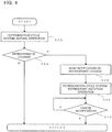
- Fig. 4 is a diagram illustrating an example of operation of the refrigeration cycle system shown in Fig. 1 .
- the refrigeration cycle system 100 is performing normal operation.
- the refrigeration cycle system 100 returns to step S02, and the normal operation is continued.
- step S04 When leakage of the refrigerant is detected in step S04, the refrigeration cycle system 100 proceeds to step S06, and a notification that the refrigerant is leaking is sent.
- the notifier 36 shown in Fig. 3 sends a notification by sound or light, and the display unit 33 displays the leakage location of the refrigerant.
- the controller 30 infers the leakage location of the refrigerant by using the position coordinates of the refrigerant leakage detection device 8 that has detected the leakage of the refrigerant, and causes the display unit 33 to display the inferred leakage location of the refrigerant.
- each refrigerant leakage detection device 8 since each refrigerant leakage detection device 8 is incorporated into the indoor unit 4, the installation position of the indoor unit 4 that includes the refrigerant leakage detection device 8 that has detected the leakage of the refrigerant is displayed on the display unit 33.
- the leakage location of the refrigerant is displayed on the display unit 33, the user that has received the notification is allowed to easily identify the location where the refrigerant is leaking, and perform maintenance or other work.
- the notification of the refrigerant leakage started in step S06 is continued until the notification is cancelled in step S10 described later.
- refrigerant agitation operation of the refrigeration cycle system 100 is executed in step S08.
- the second refrigerant leakage detection device 8-1B which is disposed closest to the second indoor unit 4-1B, detects the leakage of the refrigerant.
- the controller 30 acquires a detection result that the refrigerant is leaking, from the second refrigerant leakage detection device 8-1B, and increases the flow rate of air sent from the second indoor unit 4-1B, which is closest to the second refrigerant leakage detection device 8-1B that has detected the leakage of the refrigerant.
- the second indoor unit 4-1B is able to increase the flow rate of the sent air by increasing the rotation speed of the second fan 5-1B shown in Fig. 2 . Since the air around the second indoor unit 4-1B from which the refrigerant is leaking is agitated by increasing the flow rate of the air sent from the second indoor unit 4-1B, the concentration of the refrigerant that has leaked is inhibited from locally increasing.
- the controller 30 only needs to close the second opening-closing device 44-1B of the second indoor unit 4-1B, which is closest to the second refrigerant leakage detection device 8-1B that has detected the leakage of the refrigerant. Flow of the refrigerant into the second indoor unit 4-1B is stopped by closing the second opening-closing device 44-1B, and thus the leakage of the refrigerant from the second indoor unit 4-1B is inhibited. As a result, the concentration of the refrigerant that has leaked is inhibited from locally increasing.
- the controller 30 is also able to close the opening-closing devices 44 of all the indoor units 4 of the first refrigeration cycle apparatus 1-1 in which the second indoor unit 4-1B, which is closest to the second refrigerant leakage detection device 8-1B that has detected the leakage of the refrigerant, is connected.
- the pressure at the lower pressure side of the first compressor 20-1 of the first refrigeration cycle apparatus 1-1 decreases, low-pressure cut of the first compressor 20-1 acts, and the first compressor 20-1 stops.
- a low-pressure cut value at which the low-pressure cut of the compressor 20 is performed is preferably set to a value that is not lower than the atmospheric pressure and is made close to the atmospheric pressure.
- the controller 30 only needs to direct a flow of the air sent from at least one indoor unit 4 among the indoor units 4 other than the second indoor unit 4-1B, which is closest to the second refrigerant leakage detection device 8-1B that has detected the leakage of the refrigerant, toward the second indoor unit 4-1B.
- the indoor units 4, other than the second refrigerant leakage detection device 8-1B from which the refrigerant is leaking sending air toward the second indoor unit 4-1B, the refrigerant that has leaked is further agitated, and thus the concentration of the refrigerant that has leaked is further inhibited from locally increasing.
- the indoor units 4 other than the second indoor unit 4-1B, which send air toward the second indoor unit 4-1B from which the refrigerant is leaking, the indoor units 4 connected to the refrigeration cycle apparatuses 1 other than the first refrigeration cycle apparatus 1-1 in which the second indoor unit 4-1B is connected only need to be selected.
- the controller 30 only needs to increase the loads on the refrigeration cycle apparatuses 1 other than the first refrigeration cycle apparatus 1-1 in which the second indoor unit 4-1B closest to the second refrigerant leakage detection device 8-1B that has detected the leakage of the refrigerant is connected.
- the loads on the refrigeration cycle apparatuses 1 are increased, for example, by increasing the rotation speed of the compressors 20.
- step S10 When the notification of the refrigerant leakage is cancelled in step S10 shown in Fig. 4 , the refrigeration cycle system 100 returns to step S02, and normal operation of the refrigeration cycle system 100 is restarted.
- the cancellation of the notification of the refrigerant leakage is executed, for example, by the user who has received the notification from the notifier 36 or the display unit 33, performing an input to the input unit 34 of the controller 30, a reset switch (not shown), or other component. Since refrigerant agitation operation is continuously executed unless the notification of the refrigerant leakage is cancelled as described above, the concentration of the refrigerant that has leaked is inhibited from locally increasing. Furthermore, since the notification that the refrigerant has leaked is continuously sent unless the notification of the refrigerant leakage is cancelled, it is possible to assuredly make the user recognize that an abnormality has occurred in the refrigeration cycle system 100.
- the refrigeration cycle system 100 includes the plurality of indoor units 4 that are installed in the indoor space and each form a part of the refrigeration cycle apparatus 1 that circulates the refrigerant, the plurality of refrigerant leakage detection devices 8 that are installed in the indoor space and detect leakage of the refrigerant, and the controller 30 that acquires the detection results of the plurality of refrigerant leakage detection devices 8 and controls the refrigeration cycle apparatus 1.
- the controller 30 increases the flow rate of the air sent from the indoor unit 4 that is closest to the refrigerant leakage detection device 8 that has detected the leakage of the refrigerant.
- the controller 30 directs the flow of the air sent from at least one indoor unit 4 among the indoor units 4 other than the indoor unit 4 closest to the refrigerant leakage detection device 8 that has detected leakage of the refrigerant, toward the indoor unit 4 closest to the refrigerant leakage detection device 8 that has detected leakage of the refrigerant, it is possible to further agitate the refrigerant that has leaked. Consequently, according to Embodiment 1, it is possible to further inhibit the concentration of the refrigerant that has leaked, from locally increasing in the indoor space in the warehouse 50.
- the indoor units 4 that send air toward the indoor unit 4 closest to the refrigerant leakage detection device 8 that has detected the leakage of the refrigerant may send air at an increased flow rate.
- each of the plurality of indoor units 4 includes the opening-closing device 44 that controls flow of the refrigerant into the indoor unit 4. Since the controller 30 closes the opening-closing device 44 of the indoor unit 4 closest to the refrigerant leakage detection device 8 that has detected the leakage of the refrigerant, a possibility that the refrigerant leaks to the indoor space from the refrigeration cycle apparatus 1 in which the refrigerant is leaking is reduced. In addition, the controller 30 may close the opening-closing devices 44 of all the indoor units 4 of the refrigeration cycle apparatus 1 in which the indoor unit 4 closest to the refrigerant leakage detection device 8 that has detected leakage of the refrigerant is connected.
- the low-pressure pressure of the refrigeration cycle apparatus 1 in which the refrigerant is leaking decreases and the compressor 20 is stopped through low-pressure cut, so that a possibility of leak of the refrigerant is further reduced.
- the refrigeration cycle system 100 of Embodiment 1 also includes the plurality of refrigeration cycle apparatuses 1.
- the refrigeration cycle apparatus 1 in which the refrigerant is leaking is caused to stop circulation of the refrigerant, and the refrigeration cycle apparatus 1 in which the refrigerant is not leaking is caused to circulate the refrigerant and operate, whereby, it is possible to inhibit the temperature of the indoor space in the warehouse 50 from fluctuating.
- the controller 30 preferably increases the load on at least one refrigeration cycle apparatus 1 among the refrigeration cycle apparatuses 1 other than the refrigeration cycle apparatus 1 in which the indoor unit 4 closest to the refrigerant leakage detection device 8 that has detected leakage of the refrigerant is connected.
- the controller 30 preferably increases the load on the refrigeration cycle apparatus 1 in which the refrigerant is not leaking when circulation of the refrigerant in the refrigeration cycle apparatus 1 in which the refrigerant is leaking is stopped, it is possible to further inhibit the temperature of the indoor space in the warehouse 50 from fluctuating.
- the refrigerant applied to the refrigeration cycle apparatuses 1 of the refrigeration cycle system 100 of Embodiment 1 includes refrigerant having slight combustibility such as R32 and R1234yf
- the above effects become particularly significant. That is, the refrigerant having slight combustibility such as R32 and R1234yf may be combusted when the concentration of the refrigerant in the air is between a lower flammable limit LFL and an upper flammable limit UFL.
- the refrigerant is not combusted when it is possible to keep the concentration of the refrigerant in the indoor space lower than the lower flammable limit LFL.
- Embodiment 1 when leakage of the refrigerant has been detected, the refrigerant that has leaked is diffused, and thus the concentration of the refrigerant is inhibited from becoming equal to or higher than the lower flammable limit LFL. Consequently, according to Embodiment 1, even if refrigerant having slight combustibility has leaked to the indoor space, a possibility that the refrigerant that has leaked is combusted is reduced.
- Embodiment 1 is not limited to the above description.
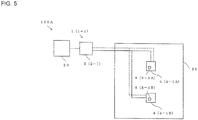
- FIG. 5 is a diagram illustrating the configuration of Modification 1 of the refrigeration cycle system according to Embodiment 1 of the present invention.
- a refrigeration cycle system 100A of Modification 1 shown in Fig. 5 includes one first refrigeration cycle apparatus 1-1 that includes one first heat source device 2-1, and a first indoor unit 4-1A and a second indoor unit 4-1B that are two indoor units 4 connected in parallel with the first heat source device 2-1.
- the refrigeration cycle system 100A of Modification 1 when the refrigerant has leaked, it is possible to diffuse the refrigerant thereby to inhibit the concentration of the refrigerant that has leaked, from locally increasing in the indoor space in the warehouse 50.
- FIG. 6 is a diagram illustrating the configuration of Modification 2 of the refrigeration cycle system according to Embodiment 1 of the present invention.
- a refrigeration cycle system 100B of Modification 2 shown in Fig. 6 includes a first refrigeration cycle apparatus 1-1 and a second refrigeration cycle apparatus 1-2 that are two refrigeration cycle apparatuses 1.
- the first refrigeration cycle apparatus 1-1 includes a first heat source device 2-1 and a first indoor unit 4-1A connected to the first heat source device 2-1
- the second refrigeration cycle apparatus 1-2 includes a second heat source device 2-2 and a third indoor unit 4-2A connected to the second heat source device 2-2.
- the refrigeration cycle apparatus 1 in which the refrigerant is leaking is caused to stop circulation of the refrigerant, and the refrigeration cycle apparatus 1 in which the refrigerant is not leaking is caused to circulate the refrigerant and operate, whereby it is possible to inhibit the temperature of the indoor space in the warehouse 50 from fluctuating.
- each refrigerant leakage detection device 8 is housed in the indoor unit 4 or installed in the vicinity of the indoor unit 4 has been described above, but the refrigeration cycle system 100 may include additional refrigerant leakage detection devices 8.
- the additional refrigerant leakage detection devices 8 are preferably disposed below the indoor units 4 in the indoor space in the warehouse 50 and on a wall, a pillar, or other structure of the warehouse 50. This is because the refrigerant has a higher density than the air, and thus the refrigerant that has leaked into the air is likely to accumulate at the lower side.
- the controller 30 is able to inhibit the concentration of the refrigerant from locally increasing in the indoor space, for example, by causing the indoor units 4 to send air toward the refrigerant leakage detection device 8 that has detected the refrigerant having a high concentration.
- the additional refrigerant leakage detection devices 8 are preferably disposed at regular intervals in the indoor space as possible, and a possibility that the concentration of the refrigerant locally increases in the indoor space is reduced when the refrigerant leakage detection devices 8 are installed at regular intervals in the indoor space.
- Embodiment 1 is not limited to the above description.
- Fig. 7 is a diagram illustrating an example of the directions of the air sent from the plurality of indoor units when the refrigerant leaks in the indoor space in the refrigeration cycle system shown in Fig. 1 .
- the refrigerant is leaking from the second indoor unit 4-1B, and the indoor units 4 other than the second indoor unit 4-1B are sending air toward the second indoor unit 4-1B.
- the direction of the air sent from the second indoor unit 4-1B is a direction that does not oppose any of the directions of the air sent from the indoor units 4 other than the second indoor unit 4-1B.
- Fig. 8 is a diagram illustrating another example of the directions of the air sent from the plurality of indoor units when the refrigerant leaks in the indoor space in the refrigeration cycle system shown in Fig. 1
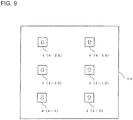
- Fig. 9 is a diagram illustrating still another example of the directions of the air sent from the plurality of indoor units when the refrigerant leaks in the indoor space in the refrigeration cycle system shown in Fig. 1 .
- Fig. 8 when the refrigerant has leaked in the indoor space, all the indoor units 4 send air to annularly circulate the refrigerant in the indoor space, whereby it is possible to inhibit the concentration of the refrigerant from locally increasing.
- Fig. 10 is a diagram illustrating still another example of the directions of the air sent from the plurality of indoor units when the refrigerant leaks in the indoor space in the refrigeration cycle system shown in Fig. 1 .
- the warehouse 50 includes a ventilator 52 for ventilating the warehouse 50 to the outside
- the refrigerant that has leaked to the interior of the warehouse 50 is discharged to the outside of the warehouse 50 by the indoor units 4 sending air toward the ventilator 52.
- the refrigeration cycle system 100 in the case where a fan that is not shown is installed in the indoor space in the warehouse 50, it is also possible to accelerate agitation of the refrigerant by adjusting the directions and the flow rates of air sent from the plurality of indoor units 4 and the fan that is not shown.
- the fan that is not shown is, for example, a circulator of which the direction and the flow rate of sent air are controlled by the controller 30.
- Fig. 11 is a diagram illustrating an example of operation of a refrigeration cycle system according to Embodiment 2 of the present invention
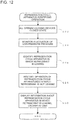
- Fig. 12 is a diagram illustrating an example of a refrigeration cycle apparatus identifying operation shown in Fig. 11 .
- the same operations as those of Fig. 4 are designated by the same reference signs and the description of the operations is omitted or simplified.
- the refrigeration cycle apparatus identifying operation is executed in step S20.
- the refrigeration cycle apparatus 1 in which the refrigerant is leaking is identified. This is because the refrigerant may be leaking from the refrigerant pipe connecting the heat source device 2 and the indoor unit 4, or the refrigerant may be leaking from a position different from a position inferred on the basis of the position of the refrigerant leakage detection device 8 that has detected the leakage of the refrigerant, depending on the directions of the air sent from the indoor units 4, and other factor.
- Embodiment 2 as described below, the refrigeration cycle apparatus 1 in which the refrigerant is leaking is identified in step S20, and circulation of the refrigerant in the refrigeration cycle apparatus 1 in which the refrigerant is leaking is stopped, whereby the leakage of the refrigerant is inhibited.
- step S06 After the notification of refrigerant leakage is sent in step S06 in Fig. 11 , the opening-closing devices 44 of all the indoor units 4 are closed in step S22 in Fig. 12 .
- all the refrigeration cycle apparatuses 1 perform pump-down stop by low-pressure cut.
- step S24 fluctuation of the low-pressure pressure of each refrigeration cycle apparatus 1 after the refrigeration cycle apparatus 1 performs the pump-down stop is monitored. For example, during a preset setting time (for example, about 3 minutes), the controller 30 acquires a detection result of a low-pressure pressure detection sensor (not shown) of each refrigeration cycle apparatus 1 and monitors fluctuation of the low-pressure pressure of each refrigeration cycle apparatus 1.
- step S26 the controller 30 identifies refrigeration cycle apparatus 1 in which the refrigerant is leaking.
- the controller 30 determines the refrigeration cycle apparatus having greater low-pressure pressure fluctuation than the other refrigeration cycle apparatuses 1, as the refrigeration cycle apparatus 1 in which the refrigerant is leaking.
- the low-pressure pressure detection sensor that is not shown is disposed in the warehouse 50 in which the temperature less fluctuates, the determination as to the refrigeration cycle apparatus 1 in which the refrigerant is leaking is further ensured.
- step S28 operation of the refrigeration cycle apparatuses 1 in which the refrigerant is determined as not being leaking is restarted. That is, the controller 30 opens the opening-closing devices 44 of the indoor units 4 of the refrigeration cycle apparatuses 1 in which the refrigerant is determined as not being leaking, and restarts operation of the compressors 20. Then, in step S30, the controller 30 causes the display unit 33 to display information regarding the refrigeration cycle apparatus 1 in which the refrigerant is leaking. For example, the controller 30 causes the display unit 33 to display the position of the indoor unit 4 closest to the refrigerant leakage detection device 8 that has detected the leakage of the refrigerant and that is included in the refrigeration cycle apparatus 1 in which the refrigerant is leaking. Then, the controller 30 proceeds to step S08 in Fig. 11 , and refrigerant agitation operation of the refrigeration cycle system 100 is executed.
- Embodiment 2 identification of the refrigeration cycle apparatus 1 in which the refrigerant is leaking is ensured as described above, and thus it is possible to inhibit the leakage of the refrigerant. In addition, in Embodiment 2, it is possible to assuredly operate the refrigeration cycle apparatuses 1 in which the refrigerant is not leaking, and thus a possibility of fluctuation of the temperature of the indoor space is reduced.
- the low-pressure cut values of the compressors 20 of all the refrigeration cycle apparatuses 1 may be values that are not less than the atmospheric pressure and are close to the atmospheric pressure. By setting the low-pressure cut values to values that are not less than the atmospheric pressure and are close to the atmospheric pressure, leakage of the refrigerant is inhibited, and a possibility of entry of air into a refrigerant pipe of each refrigeration cycle apparatus 1 or other component is reduced.
- the low-pressure cut values of the compressors 20 of all the refrigeration cycle apparatuses 1 are preferably equal to each other. By making the low-pressure cut values of the compressors 20 of all the refrigeration cycle apparatuses 1 equal to each other, it is possible to simplify the determination as to the refrigeration cycle apparatus 1 in which the refrigerant is leaking.
- Embodiments 1 and 2 described above, and various modifications may be made within the scope of the present invention. That is, the components of Embodiments 1 and 2 described above may be modified as appropriate, and at least a part of the components may be replaced with another component. Furthermore, a component whose location is not specified does not necessarily need to be disposed at the location disclosed in Embodiment 1 or 2, and may be disposed at any location that allows the component to perform its function.
- each refrigeration cycle apparatus 1 may include an oil separator, a gas-liquid separator, a liquid receiver, and other component that are not shown.
- each refrigeration cycle apparatus 1 includes a flow path switching device such as a four-way valve, it is possible to selectively switch heating or cooling by the use side heat exchangers 40.
- each refrigeration cycle apparatus may be an integrated unit (for example, a compressor-built-in showcase, an air-conditioning machine, or a dehumidification machine) into which a compressor, a heat source side heat exchanger, an expanding device, a use side heat exchanger, and an opening-closing device are packaged, and even a refrigeration cycle system including such refrigeration cycle apparatuses is able to achieve the above-described advantageous effects.
- a compressor-built-in showcase for example, an air-conditioning machine, or a dehumidification machine
- a compressor, a heat source side heat exchanger, an expanding device, a use side heat exchanger, and an opening-closing device are packaged, and even a refrigeration cycle system including such refrigeration cycle apparatuses is able to achieve the above-described advantageous effects.
Landscapes
- Engineering & Computer Science (AREA)
- Chemical & Material Sciences (AREA)
- Combustion & Propulsion (AREA)
- Mechanical Engineering (AREA)
- General Engineering & Computer Science (AREA)
- Physics & Mathematics (AREA)
- Fluid Mechanics (AREA)
- Air Conditioning Control Device (AREA)
- Compression-Type Refrigeration Machines With Reversible Cycles (AREA)
Abstract
Description
- The present invention relates to a refrigeration cycle system including a plurality of indoor units and a plurality of refrigerant leakage detection devices.
- An air-conditioning apparatus including a refrigerant leakage sensor has been known (see, for example, Patent Literature 1). In the existing air-conditioning apparatus disclosed in
Patent Literature 1, when leakage of refrigerant has been detected, a compressor and a fan motor are stopped, and a refrigerant circuit is shut off by a solenoid shutoff valve, thereby inhibiting the leakage of the refrigerant. - Patent Literature 1: Japanese Unexamined Patent Application Publication No.
10-281569 - However, in the existing refrigeration cycle apparatus disclosed in
Patent Literature 1, for example, the concentration of the refrigerant that has leaked may locally increase in the vicinity of the leakage location of the refrigerant. - The present invention has been made in view of the above-described problem, and it is an object of the present invention to provide a refrigeration cycle system that inhibits the concentration of refrigerant that has leaked, from locally increasing, when the refrigerant has leaked.
- A refrigeration cycle system according to an embodiment of the present invention includes a plurality of indoor units installed in an indoor space and each forming a part of a refrigeration cycle apparatus configured to circulate refrigerant, a plurality of refrigerant leakage detection devices installed in the indoor space and each configured to detect leakage of the refrigerant, and a controller configured to acquire detection results of the plurality of refrigerant leakage detection devices and control the refrigeration cycle apparatus. When the refrigerant leakage detection device detects leakage of the refrigerant, the controller increases a flow rate of air sent from the indoor unit closest to the refrigerant leakage detection device that detects the leakage of the refrigerant.
- According to an embodiment of the present invention, it is possible to obtain a refrigeration cycle system that inhibits the concentration of the refrigerant that has leaked, from locally increasing, when the refrigerant has leaked.
-
- [
Fig. 1] Fig. 1 is a diagram illustrating an example of the configuration of a refrigeration cycle system according toEmbodiment 1 of the present invention. - [
Fig. 2] Fig. 2 is a diagram illustrating an example of the configuration of a refrigeration cycle apparatus shown inFig. 1 . - [
Fig. 3] Fig. 3 is a diagram illustrating an example of the configuration of a controller shown inFig. 1 . - [
Fig. 4] Fig. 4 is a diagram illustrating an example of operation of the refrigeration cycle system shown inFig. 1 . - [
Fig. 5] Fig. 5 is a diagram illustrating the configuration ofModification 1 of the refrigeration cycle system according toEmbodiment 1 of the present invention. - [
Fig. 6] Fig. 6 is a diagram illustrating the configuration ofModification 2 of the refrigeration cycle system according toEmbodiment 1 of the present invention. - [
Fig. 7] Fig. 7 is a diagram illustrating an example of the directions of air sent from a plurality of indoor units when refrigerant has leaked in an indoor space in the refrigeration cycle system shown inFig. 1 . - [
Fig. 8] Fig. 8 is a diagram illustrating another example of the directions of the air sent from the plurality of indoor units when the refrigerant has leaked in the indoor space in the refrigeration cycle system shown inFig. 1 . - [
Fig. 9] Fig. 9 is a diagram illustrating still another example of the directions of the air sent from the plurality of indoor units when the refrigerant has leaked in the indoor space in the refrigeration cycle system shown inFig. 1 . - [
Fig. 10] Fig. 10 is a diagram illustrating still another example of the directions of the air sent from the plurality of indoor units when the refrigerant has leaked in the indoor space in the refrigeration cycle system shown inFig. 1 . - [
Fig. 11] Fig. 11 is a diagram illustrating an example of operation of a refrigeration cycle system according toEmbodiment 2 of the present invention. - [
Fig. 12] Fig. 12 is a diagram illustrating an example of a refrigeration cycle apparatus identifying operation shown inFig. 11 . - Hereinafter, Embodiments of the present invention will be described with reference to the drawings. In each drawing, the same or corresponding components are denoted by the same reference signs, and the description of the components is omitted or simplified as appropriate. The shapes, sizes, arrangement, and other aspects of the components illustrated in each drawing may be changed as appropriate within the scope of the present invention.
-
Fig. 1 is a diagram illustrating an example of the configuration of a refrigeration cycle system according toEmbodiment 1 of the present invention. Therefrigeration cycle system 100 shown inFig. 1 is applied to, for example, a unit cooler that cools an indoor space in awarehouse 50, and includes a plurality ofrefrigeration cycle apparatuses 1 and acontroller 30 that controls the plurality ofrefrigeration cycle apparatuses 1. Therefrigeration cycle system 100 is also applicable to an air-conditioning system that performs air-conditioning of the indoor space of a room. InFig. 1 , solid lines that connectheat source devices 2 andindoor units 4 schematically illustrate refrigerant pipes, and broken lines that connect theheat source devices 2 andindoor units 4 and broken lines that connect theheat source devices 2 and thecontroller 30 schematically illustrate communication lines. - The
refrigeration cycle apparatuses 1 circulate refrigerant, and theheat source devices 2 and theindoor units 4 are connected to each other via the refrigerant pipes. In addition, theheat source devices 2 and theindoor units 4 are connected to each other via the communication lines, and controllers (not shown) of theheat source devices 2 and controllers (not shown) of theindoor units 4 control therefrigeration cycle apparatuses 1 while communicating with each other. The refrigerant used for therefrigeration cycle apparatuses 1 includes R32 or R1234yf, but may be another type of refrigerant. In addition, therefrigeration cycle system 100 shown inFig. 1 includes fourrefrigeration cycle apparatuses 1, that is, a first refrigeration cycle apparatus 1-1, a second refrigeration cycle apparatus 1-2, a third refrigeration cycle apparatus 1-3, and a fourth refrigeration cycle apparatus 1-4. Therefrigeration cycle system 100 only needs to include one or morerefrigeration cycle apparatuses 1. - The first refrigeration cycle apparatus 1-1 includes a first heat source device 2-1, and a first indoor unit 4-1A and a second indoor unit 4-1B connected in parallel with the first heat source device 2-1. The second refrigeration cycle apparatus 1-2 includes a second heat source device 2-2, and a third indoor unit 4-2A and a fourth indoor unit 4-2B connected in parallel with the second heat source device 2-2. The third refrigeration cycle apparatus 1-3 includes a third heat source device 2-3, and a fifth indoor unit 4-3 connected to the third heat source device 2-3. The fourth refrigeration cycle apparatus 1-4 includes a fourth heat source device 2-4 and a sixth indoor unit 4-4 connected to the fourth heat source device 2-4. Each of the plurality of
refrigeration cycle apparatuses 1 only needs to include one or moreindoor units 4, and may include three or moreindoor units 4, for example. - Each
indoor unit 4 according toEmbodiment 1 accommodates a refrigerantleakage detection device 8 that detects leakage of the refrigerant. That is, the first indoor unit 4-1A includes a first refrigerant leakage detection device 8-1A, the second indoor unit 4-1B includes a second refrigerant leakage detection device 8-1B, the third indoor unit 4-2A includes a third refrigerant leakage detection device 8-2A, the fourth indoor unit 4-2B includes a fourth refrigerant leakage detection device 8-2B, the fifth indoor unit 4-3 includes a fifth refrigerant leakage detection device 8-3, and the sixth indoor unit 4-4 includes a sixth refrigerant leakage detection device 8-4. The refrigerantleakage detection devices 8 may be each provided in the vicinity of a corresponding one of theindoor units 4. The refrigerantleakage detection devices 8 that are housed in theindoor units 4 or provided in the vicinity of theindoor units 4 are able to detect leakage of the refrigerant early when the refrigerant has leaked in the indoor space in thewarehouse 50. In the case where the refrigerantleakage detection devices 8 are provided close to theindoor units 4, for example, the refrigerantleakage detection devices 8 are configured as devices separate from theindoor units 4 and are connected to theindoor units 4 or thecontroller 30 via the communication lines. For example, the refrigerantleakage detection devices 8 are preferably provided close to flare connection portions of the refrigerant pipes at which the refrigerant may leak. -
Fig. 2 is a diagram illustrating an example of the configuration of the refrigeration cycle apparatus shown inFig. 1 . In the following, for easy understanding ofEmbodiment 1, only the first refrigeration cycle apparatus 1-1 will be described with referenced toFig. 2 , and the description of the second refrigeration cycle apparatus 1-2, the third refrigeration cycle apparatus 1-3, and the fourth refrigeration cycle apparatus 1-4 is omitted since the second refrigeration cycle apparatus 1-2, the third refrigeration cycle apparatus 1-3, and the fourth refrigeration cycle apparatus 1-4 have the same configuration as the first refrigeration cycle apparatus 1-1. Hereinafter, the first refrigeration cycle apparatus 1-1 is sometimes described as therefrigeration cycle apparatus 1, the first heat source device 2-1 is sometimes described as theheat source device 2, a first compressor 20-1 is sometimes described as acompressor 20, a first heat source side heat exchanger 22-1 is sometimes described as a heat sourceside heat exchanger 22, the first indoor unit 4-1A and the second indoor unit 4-1B are sometimes described as theindoor unit 4, a first fan 5-1A and a second fan 5-1B are sometimes described as afan 5, a first wind direction controller 6-1A and a second wind direction controller 6-1B are sometimes described as awind direction controller 6, the first refrigerant leakage detection device 8-1A and the second refrigerant leakage detection device 8-1B are sometimes described as the refrigerantleakage detection device 8, a first use side heat exchanger 40-1A and a second use side heat exchanger 40-1B are sometimes described as a useside heat exchanger 40, a first expanding device 42-1A and a second expanding device 42-1B are sometimes described as an expandingdevice 42, and a first opening-closing device 44-1A and a second opening-closing device 44-1B are sometimes described as an opening-closing device 44. - The
heat source device 2 shown inFig. 2 is installed, for example, outdoor, that is, outside thewarehouse 50, and includes thecompressor 20 and the heat sourceside heat exchanger 22. Thecompressor 20 sucks the refrigerant, compresses the refrigerant, and discharges the refrigerant in a high-temperature and high-pressure state. Thecompressor 20 is, for example, a capacity-controllable inverter compressor, but may be of a constant speed type. The heat sourceside heat exchanger 22 exchanges heat between the refrigerant and air, for example. For example, an air-sending fan (not shown) that sends air to the heat sourceside heat exchanger 22 is installed in the vicinity of the heat sourceside heat exchanger 22. - The
indoor unit 4 is installed in the indoor space in thewarehouse 50, and includes the useside heat exchanger 40, the expandingdevice 42, and the opening-closing device 44. The expandingdevice 42 expands the refrigerant, and is, for example, a LEV (linear electronic expansion valve) of which an opening degree is adjustable, but may be a capillary tube or other component of which an opening degree is not adjustable. The opening-closing device 44 controls flow of the refrigerant into the useside heat exchanger 40 and is composed of an opening-closing valve, for example. The useside heat exchanger 40 exchanges heat between the refrigerant and air. Thefan 5 that sends air to the useside heat exchanger 40 is installed in the vicinity of the useside heat exchanger 40. Thefan 5 is able to adjust the flow rate of sent air by controlling a rotation speed of thefan 5. The air around theindoor unit 4 in thewarehouse 50 is sucked into theindoor unit 4 by thefan 5 operating. The air sucked into theindoor unit 4 is subjected to heat exchange by the useside heat exchanger 40 and is blown out from theindoor unit 4 to the interior of thewarehouse 50. In addition, theindoor unit 4 includes thewind direction controller 6 that controls the direction of air blown out from theindoor unit 4. Thewind direction controller 6 is configured to include a louver formed of a plurality of plate-like members. - Next, an example of operation of the
refrigeration cycle apparatus 1 will be described. The refrigerant compressed by thecompressor 20 of theheat source device 2 flows through the heat sourceside heat exchanger 22 and is condensed in the heat sourceside heat exchanger 22. The refrigerant condensed by the heat sourceside heat exchanger 22 flows out from theheat source device 2 and flows into theindoor unit 4. In the example shown inFig. 2 , the refrigerant having flowed out from theheat source device 2 is split into refrigerant flowing to the first indoor unit 4-1A and refrigerant flowing to the second indoor unit 4-1B. The refrigerant having flowed into the first indoor unit 4-1A passes through the first opening-closing device 44-1A and is expanded by the first expanding device 42-1A. The refrigerant expanded by the first expanding device 42-1A flows through the first use side heat exchanger 40-1A and is evaporated in the first use side heat exchanger 40-1A. The refrigerant evaporated by the first use side heat exchanger 40-1A flows out from the first indoor unit 4-1A and joins the refrigerant having flowed out from the second indoor unit 4-1B. Meanwhile, the refrigerant having flowed into the second indoor unit 4-1B passes through the second opening-closing device 44-1B and is expanded by the second expanding device 42-1B. The refrigerant expanded by the second expanding device 42-1B flows through the second use side heat exchanger 40-1B and is evaporated in the second use side heat exchanger 40-1B. The refrigerant evaporated by the second use side heat exchanger 40-1B flows out from the second indoor unit 4-1B and joins the refrigerant having flowed out from the first indoor unit 4-1A. The refrigerant into which the refrigerant having flowed out from the first indoor unit 4-1A and the refrigerant having flowed out from the second indoor unit 4-1B have joined flows into theheat source device 2 and is sucked into thecompressor 20 and compressed in thecompressor 20 again. -
Fig. 3 is a diagram illustrating an example of the configuration of the controller shown inFig. 1 . Thecontroller 30 controls the entirety of therefrigeration cycle system 100 and is configured to include an analog circuit, a digital circuit, and a CPU, or a combination of two or more of these. For example, thecontroller 30 is able to acquire detection results from the refrigerantleakage detection device 8, a pressure sensor (not shown), a temperature sensor (not shown), and other component and control eachrefrigeration cycle apparatus 1. - As shown in
Fig. 3 , thecontroller 30 includes a communicator 31, a processor 32, a display unit 33, aninput unit 34, amemory 35, and a notifier 36. The communicator 31 serves to communicate with each of the plurality ofrefrigeration cycle apparatuses 1. Thecontroller 30 and each of the plurality ofrefrigeration cycle apparatuses 1 are able to perform wired or wireless type communication via the communicator 31. The processor 32 serves to perform preset processing by using information input from theinput unit 34, information acquired from thememory 35, or information acquired from each of the plurality ofrefrigeration cycle apparatuses 1, and other information, for example. The display unit 33 serves to display the status of therefrigeration cycle system 100 and other information, and is configured to include a liquid crystal screen, for example. Theinput unit 34 allows an instruction to be input by, for example, a user or other personnel to therefrigeration cycle system 100, and is configured to include a switch, for example. For example, the user or other personnel is allowed to give instructions regarding a target temperature for the indoor space to the plurality ofrefrigeration cycle apparatuses 1 by using theinput unit 34. The display unit 33 and theinput unit 34 may be integrated with each other to form a touch panel or other component. Thememory 35 is configured to include a non-volatile memory, for example, and stores a control program for controlling therefrigeration cycle system 100. For example, thememory 35 stores position coordinates regarding the position of each of the plurality ofindoor units 4, position coordinates regarding the position of each of the plurality of refrigerantleakage detection devices 8, and other information. For example, an operator that is the user inputs the position coordinates regarding the position of each of the plurality ofindoor units 4 and the position coordinates regarding the position of each of the plurality of refrigerantleakage detection devices 8 by using theinput unit 34 when the operator has installed theindoor units 4 and the refrigerantleakage detection devices 8. The notifier 36 serves to send a notification, and is configured to include an indicator that sends a notification by light, or a buzzer that sends a notification by sound, or other component, for example. In the case where thecontroller 30 sends a notification by using the display unit 33, it is possible to omit the notifier 36. -
Fig. 4 is a diagram illustrating an example of operation of the refrigeration cycle system shown inFig. 1 . In step S02 inFig. 4 , therefrigeration cycle system 100 is performing normal operation. When leakage of the refrigerant is not detected in step S04, therefrigeration cycle system 100 returns to step S02, and the normal operation is continued. - When leakage of the refrigerant is detected in step S04, the
refrigeration cycle system 100 proceeds to step S06, and a notification that the refrigerant is leaking is sent. For example, when leakage of the refrigerant is detected, the notifier 36 shown inFig. 3 sends a notification by sound or light, and the display unit 33 displays the leakage location of the refrigerant. For example, thecontroller 30 infers the leakage location of the refrigerant by using the position coordinates of the refrigerantleakage detection device 8 that has detected the leakage of the refrigerant, and causes the display unit 33 to display the inferred leakage location of the refrigerant. InEmbodiment 1, since each refrigerantleakage detection device 8 is incorporated into theindoor unit 4, the installation position of theindoor unit 4 that includes the refrigerantleakage detection device 8 that has detected the leakage of the refrigerant is displayed on the display unit 33. When the leakage location of the refrigerant is displayed on the display unit 33, the user that has received the notification is allowed to easily identify the location where the refrigerant is leaking, and perform maintenance or other work. The notification of the refrigerant leakage started in step S06 is continued until the notification is cancelled in step S10 described later. - After the notification of the refrigerant leakage is sent in step S06, refrigerant agitation operation of the
refrigeration cycle system 100 is executed in step S08. For example, in the example shown inFig. 1 , when the refrigerant leaks from the second indoor unit 4-1B, the second refrigerant leakage detection device 8-1B, which is disposed closest to the second indoor unit 4-1B, detects the leakage of the refrigerant. Thecontroller 30 acquires a detection result that the refrigerant is leaking, from the second refrigerant leakage detection device 8-1B, and increases the flow rate of air sent from the second indoor unit 4-1B, which is closest to the second refrigerant leakage detection device 8-1B that has detected the leakage of the refrigerant. For example, the second indoor unit 4-1B is able to increase the flow rate of the sent air by increasing the rotation speed of the second fan 5-1B shown inFig. 2 . Since the air around the second indoor unit 4-1B from which the refrigerant is leaking is agitated by increasing the flow rate of the air sent from the second indoor unit 4-1B, the concentration of the refrigerant that has leaked is inhibited from locally increasing. - During refrigerant agitation operation in step S08, the
controller 30 only needs to close the second opening-closing device 44-1B of the second indoor unit 4-1B, which is closest to the second refrigerant leakage detection device 8-1B that has detected the leakage of the refrigerant. Flow of the refrigerant into the second indoor unit 4-1B is stopped by closing the second opening-closing device 44-1B, and thus the leakage of the refrigerant from the second indoor unit 4-1B is inhibited. As a result, the concentration of the refrigerant that has leaked is inhibited from locally increasing. - During refrigerant agitation operation in step S08, the
controller 30 is also able to close the opening-closingdevices 44 of all theindoor units 4 of the first refrigeration cycle apparatus 1-1 in which the second indoor unit 4-1B, which is closest to the second refrigerant leakage detection device 8-1B that has detected the leakage of the refrigerant, is connected. By closing the first opening-closing device 44-1A and the second opening-closing device 44-1 B shown inFig. 2 , the pressure at the lower pressure side of the first compressor 20-1 of the first refrigeration cycle apparatus 1-1 decreases, low-pressure cut of the first compressor 20-1 acts, and the first compressor 20-1 stops. Since the first compressor 20-1 stops and the pressure at the low-pressure side of the first refrigeration cycle apparatus 1-1 decreases, the leakage of the refrigerant from the second indoor unit 4-1B is further assuredly inhibited. As a result, the concentration of the refrigerant that has leaked is inhibited from locally increasing. A low-pressure cut value at which the low-pressure cut of thecompressor 20 is performed is preferably set to a value that is not lower than the atmospheric pressure and is made close to the atmospheric pressure. By setting the low-pressure cut value to be not lower than the atmospheric pressure and to be close to the atmospheric pressure, the leakage of the refrigerant is inhibited, and a possibility that air enters the refrigerant pipe of therefrigeration cycle apparatus 1 and other component is inhibited. - During refrigerant agitation operation in step S08, the
controller 30 only needs to direct a flow of the air sent from at least oneindoor unit 4 among theindoor units 4 other than the second indoor unit 4-1B, which is closest to the second refrigerant leakage detection device 8-1B that has detected the leakage of the refrigerant, toward the second indoor unit 4-1B. By theindoor units 4, other than the second refrigerant leakage detection device 8-1B from which the refrigerant is leaking, sending air toward the second indoor unit 4-1B, the refrigerant that has leaked is further agitated, and thus the concentration of the refrigerant that has leaked is further inhibited from locally increasing. As theindoor units 4, other than the second indoor unit 4-1B, which send air toward the second indoor unit 4-1B from which the refrigerant is leaking, theindoor units 4 connected to therefrigeration cycle apparatuses 1 other than the first refrigeration cycle apparatus 1-1 in which the second indoor unit 4-1B is connected only need to be selected. By theindoor units 4, through which the refrigerant is circulating, sending air to a region on which theindoor unit 4 through which the refrigerant is not circulating performs air-conditioning, the temperature of the interior of thewarehouse 50 is inhibited from locally changing. - During refrigerant agitation operation in step S08, the
controller 30 only needs to increase the loads on therefrigeration cycle apparatuses 1 other than the first refrigeration cycle apparatus 1-1 in which the second indoor unit 4-1B closest to the second refrigerant leakage detection device 8-1B that has detected the leakage of the refrigerant is connected. By increasing the loads on therefrigeration cycle apparatuses 1 other than the first refrigeration cycle apparatus 1-1 in which the refrigerant is leaking, the temperature of the interior of thewarehouse 50 is inhibited from fluctuating. The loads on therefrigeration cycle apparatuses 1 are increased, for example, by increasing the rotation speed of thecompressors 20. - When the notification of the refrigerant leakage is cancelled in step S10 shown in
Fig. 4 , therefrigeration cycle system 100 returns to step S02, and normal operation of therefrigeration cycle system 100 is restarted. The cancellation of the notification of the refrigerant leakage is executed, for example, by the user who has received the notification from the notifier 36 or the display unit 33, performing an input to theinput unit 34 of thecontroller 30, a reset switch (not shown), or other component. Since refrigerant agitation operation is continuously executed unless the notification of the refrigerant leakage is cancelled as described above, the concentration of the refrigerant that has leaked is inhibited from locally increasing. Furthermore, since the notification that the refrigerant has leaked is continuously sent unless the notification of the refrigerant leakage is cancelled, it is possible to assuredly make the user recognize that an abnormality has occurred in therefrigeration cycle system 100. - As described above, the
refrigeration cycle system 100 according toEmbodiment 1 includes the plurality ofindoor units 4 that are installed in the indoor space and each form a part of therefrigeration cycle apparatus 1 that circulates the refrigerant, the plurality of refrigerantleakage detection devices 8 that are installed in the indoor space and detect leakage of the refrigerant, and thecontroller 30 that acquires the detection results of the plurality of refrigerantleakage detection devices 8 and controls therefrigeration cycle apparatus 1. When the refrigerantleakage detection device 8 has detected leakage of the refrigerant, thecontroller 30 increases the flow rate of the air sent from theindoor unit 4 that is closest to the refrigerantleakage detection device 8 that has detected the leakage of the refrigerant. Consequently, in therefrigeration cycle system 100 ofEmbodiment 1, even when the refrigerant leaks in the indoor space in thewarehouse 50, the refrigerant that has leaked is diffused, and thus it is possible to inhibit the concentration of the refrigerant that has leaked, from locally increasing in the indoor space in thewarehouse 50. - In
Embodiment 1, since thecontroller 30 directs the flow of the air sent from at least oneindoor unit 4 among theindoor units 4 other than theindoor unit 4 closest to the refrigerantleakage detection device 8 that has detected leakage of the refrigerant, toward theindoor unit 4 closest to the refrigerantleakage detection device 8 that has detected leakage of the refrigerant, it is possible to further agitate the refrigerant that has leaked. Consequently, according toEmbodiment 1, it is possible to further inhibit the concentration of the refrigerant that has leaked, from locally increasing in the indoor space in thewarehouse 50. Theindoor units 4 that send air toward theindoor unit 4 closest to the refrigerantleakage detection device 8 that has detected the leakage of the refrigerant may send air at an increased flow rate. - In
Embodiment 1, each of the plurality ofindoor units 4 includes the opening-closingdevice 44 that controls flow of the refrigerant into theindoor unit 4. Since thecontroller 30 closes the opening-closingdevice 44 of theindoor unit 4 closest to the refrigerantleakage detection device 8 that has detected the leakage of the refrigerant, a possibility that the refrigerant leaks to the indoor space from therefrigeration cycle apparatus 1 in which the refrigerant is leaking is reduced. In addition, thecontroller 30 may close the opening-closingdevices 44 of all theindoor units 4 of therefrigeration cycle apparatus 1 in which theindoor unit 4 closest to the refrigerantleakage detection device 8 that has detected leakage of the refrigerant is connected. By closing the opening-closingdevices 44 of all theindoor units 4 of therefrigeration cycle apparatus 1 in which the refrigerant is leaking, the low-pressure pressure of therefrigeration cycle apparatus 1 in which the refrigerant is leaking decreases and thecompressor 20 is stopped through low-pressure cut, so that a possibility of leak of the refrigerant is further reduced. - The
refrigeration cycle system 100 ofEmbodiment 1 also includes the plurality ofrefrigeration cycle apparatuses 1. Therefrigeration cycle apparatus 1 in which the refrigerant is leaking is caused to stop circulation of the refrigerant, and therefrigeration cycle apparatus 1 in which the refrigerant is not leaking is caused to circulate the refrigerant and operate, whereby, it is possible to inhibit the temperature of the indoor space in thewarehouse 50 from fluctuating. - For example, the
controller 30 preferably increases the load on at least onerefrigeration cycle apparatus 1 among therefrigeration cycle apparatuses 1 other than therefrigeration cycle apparatus 1 in which theindoor unit 4 closest to the refrigerantleakage detection device 8 that has detected leakage of the refrigerant is connected. By increasing the load on therefrigeration cycle apparatus 1 in which the refrigerant is not leaking when circulation of the refrigerant in therefrigeration cycle apparatus 1 in which the refrigerant is leaking is stopped, it is possible to further inhibit the temperature of the indoor space in thewarehouse 50 from fluctuating. In addition, by directing the flow of the air sent from theindoor unit 4 of therefrigeration cycle apparatus 1 on which the load is increased, toward the region on which theindoor unit 4 from which the refrigerant is leaking performs air-conditioning, it is possible to inhibit the temperature of the indoor space in thewarehouse 50 from locally fluctuating. - When the refrigerant applied to the
refrigeration cycle apparatuses 1 of therefrigeration cycle system 100 ofEmbodiment 1 includes refrigerant having slight combustibility such as R32 and R1234yf, the above effects become particularly significant. That is, the refrigerant having slight combustibility such as R32 and R1234yf may be combusted when the concentration of the refrigerant in the air is between a lower flammable limit LFL and an upper flammable limit UFL. Thus, even if the refrigerant leaks to the indoor space, the refrigerant is not combusted when it is possible to keep the concentration of the refrigerant in the indoor space lower than the lower flammable limit LFL. InEmbodiment 1, when leakage of the refrigerant has been detected, the refrigerant that has leaked is diffused, and thus the concentration of the refrigerant is inhibited from becoming equal to or higher than the lower flammable limit LFL. Consequently, according toEmbodiment 1, even if refrigerant having slight combustibility has leaked to the indoor space, a possibility that the refrigerant that has leaked is combusted is reduced. -
Embodiment 1 is not limited to the above description. - For example,
Fig. 5 is a diagram illustrating the configuration ofModification 1 of the refrigeration cycle system according toEmbodiment 1 of the present invention. A refrigeration cycle system 100A ofModification 1 shown inFig. 5 includes one first refrigeration cycle apparatus 1-1 that includes one first heat source device 2-1, and a first indoor unit 4-1A and a second indoor unit 4-1B that are twoindoor units 4 connected in parallel with the first heat source device 2-1. Also in the refrigeration cycle system 100A ofModification 1, when the refrigerant has leaked, it is possible to diffuse the refrigerant thereby to inhibit the concentration of the refrigerant that has leaked, from locally increasing in the indoor space in thewarehouse 50. - For example,
Fig. 6 is a diagram illustrating the configuration ofModification 2 of the refrigeration cycle system according toEmbodiment 1 of the present invention. A refrigeration cycle system 100B ofModification 2 shown inFig. 6 includes a first refrigeration cycle apparatus 1-1 and a second refrigeration cycle apparatus 1-2 that are tworefrigeration cycle apparatuses 1. The first refrigeration cycle apparatus 1-1 includes a first heat source device 2-1 and a first indoor unit 4-1A connected to the first heat source device 2-1, and the second refrigeration cycle apparatus 1-2 includes a second heat source device 2-2 and a third indoor unit 4-2A connected to the second heat source device 2-2. Also in the refrigeration cycle system 100B ofModification 2, when the refrigerant has leaked, it is possible to diffuse the refrigerant thereby to inhibit the concentration of the refrigerant that has leaked, from locally increasing in the indoor space in thewarehouse 50. In addition, in the refrigeration cycle system 100B ofModification 2, therefrigeration cycle apparatus 1 in which the refrigerant is leaking is caused to stop circulation of the refrigerant, and therefrigeration cycle apparatus 1 in which the refrigerant is not leaking is caused to circulate the refrigerant and operate, whereby it is possible to inhibit the temperature of the indoor space in thewarehouse 50 from fluctuating. - For example, the example in which each refrigerant
leakage detection device 8 is housed in theindoor unit 4 or installed in the vicinity of theindoor unit 4 has been described above, but therefrigeration cycle system 100 may include additional refrigerantleakage detection devices 8. For example, the additional refrigerantleakage detection devices 8 are preferably disposed below theindoor units 4 in the indoor space in thewarehouse 50 and on a wall, a pillar, or other structure of thewarehouse 50. This is because the refrigerant has a higher density than the air, and thus the refrigerant that has leaked into the air is likely to accumulate at the lower side. For example, when the concentration of the refrigerant has increased at the lower side of the indoor space, the refrigerant that has leaked is agitated by theindoor units 4 sending air toward the lower side, whereby the concentration of the refrigerant that has leaked is inhibited from locally increasing. Thecontroller 30 is able to inhibit the concentration of the refrigerant from locally increasing in the indoor space, for example, by causing theindoor units 4 to send air toward the refrigerantleakage detection device 8 that has detected the refrigerant having a high concentration. In addition, the additional refrigerantleakage detection devices 8 are preferably disposed at regular intervals in the indoor space as possible, and a possibility that the concentration of the refrigerant locally increases in the indoor space is reduced when the refrigerantleakage detection devices 8 are installed at regular intervals in the indoor space. - For example, the example in which at least one
indoor unit 4 among theindoor units 4 other than theindoor unit 4 from which the refrigerant is leaking sends air toward theindoor unit 4 from which the refrigerant is leaking has been described above, butEmbodiment 1 is not limited to the above description. - For example,
Fig. 7 is a diagram illustrating an example of the directions of the air sent from the plurality of indoor units when the refrigerant leaks in the indoor space in the refrigeration cycle system shown inFig. 1 . In the example shown inFig. 7 , the refrigerant is leaking from the second indoor unit 4-1B, and theindoor units 4 other than the second indoor unit 4-1B are sending air toward the second indoor unit 4-1B. The direction of the air sent from the second indoor unit 4-1B is a direction that does not oppose any of the directions of the air sent from theindoor units 4 other than the second indoor unit 4-1B. When all theindoor units 4 other than theindoor unit 4 from which the refrigerant is leaking send air toward theindoor unit 4 from which the refrigerant is leaking as shown inFig. 7 , it is possible to rapidly agitate the refrigerant that has leaked. - For example,
Fig. 8 is a diagram illustrating another example of the directions of the air sent from the plurality of indoor units when the refrigerant leaks in the indoor space in the refrigeration cycle system shown inFig. 1 , andFig. 9 is a diagram illustrating still another example of the directions of the air sent from the plurality of indoor units when the refrigerant leaks in the indoor space in the refrigeration cycle system shown inFig. 1 . As shown inFig. 8 , when the refrigerant has leaked in the indoor space, all theindoor units 4 send air to annularly circulate the refrigerant in the indoor space, whereby it is possible to inhibit the concentration of the refrigerant from locally increasing. In addition, when it is not possible to freely adjust the directions of the air sent from theindoor units 4 as shown inFig. 8 , it is only necessary to adjust the direction of the air sent from each of the plurality ofindoor units 4 such that, as shown inFig. 9 , the direction of the sent air does not oppose any other direction of the sent air. - For example,
Fig. 10 is a diagram illustrating still another example of the directions of the air sent from the plurality of indoor units when the refrigerant leaks in the indoor space in the refrigeration cycle system shown inFig. 1 . As shown inFig. 10 , in the case where thewarehouse 50 includes a ventilator 52 for ventilating thewarehouse 50 to the outside, when the refrigerant has leaked in the indoor space, the refrigerant that has leaked to the interior of thewarehouse 50 is discharged to the outside of thewarehouse 50 by theindoor units 4 sending air toward the ventilator 52. - In the
refrigeration cycle system 100, in the case where a fan that is not shown is installed in the indoor space in thewarehouse 50, it is also possible to accelerate agitation of the refrigerant by adjusting the directions and the flow rates of air sent from the plurality ofindoor units 4 and the fan that is not shown. The fan that is not shown is, for example, a circulator of which the direction and the flow rate of sent air are controlled by thecontroller 30. -
Fig. 11 is a diagram illustrating an example of operation of a refrigeration cycle system according toEmbodiment 2 of the present invention, andFig. 12 is a diagram illustrating an example of a refrigeration cycle apparatus identifying operation shown inFig. 11 . In the operation ofFig. 11 , the same operations as those ofFig. 4 are designated by the same reference signs and the description of the operations is omitted or simplified. - As shown in
Fig. 11 , inEmbodiment 2, after a notification of refrigerant leakage is sent in step S06, the refrigeration cycle apparatus identifying operation is executed in step S20. In the refrigeration cycle apparatus identifying operation in step S20, therefrigeration cycle apparatus 1 in which the refrigerant is leaking is identified. This is because the refrigerant may be leaking from the refrigerant pipe connecting theheat source device 2 and theindoor unit 4, or the refrigerant may be leaking from a position different from a position inferred on the basis of the position of the refrigerantleakage detection device 8 that has detected the leakage of the refrigerant, depending on the directions of the air sent from theindoor units 4, and other factor. Consequently, inEmbodiment 2, as described below, therefrigeration cycle apparatus 1 in which the refrigerant is leaking is identified in step S20, and circulation of the refrigerant in therefrigeration cycle apparatus 1 in which the refrigerant is leaking is stopped, whereby the leakage of the refrigerant is inhibited. - After the notification of refrigerant leakage is sent in step S06 in
Fig. 11 , the opening-closingdevices 44 of all theindoor units 4 are closed in step S22 inFig. 12 . When the opening-closingdevices 44 of all theindoor units 4 are closed, all therefrigeration cycle apparatuses 1 perform pump-down stop by low-pressure cut. In step S24, fluctuation of the low-pressure pressure of eachrefrigeration cycle apparatus 1 after therefrigeration cycle apparatus 1 performs the pump-down stop is monitored. For example, during a preset setting time (for example, about 3 minutes), thecontroller 30 acquires a detection result of a low-pressure pressure detection sensor (not shown) of eachrefrigeration cycle apparatus 1 and monitors fluctuation of the low-pressure pressure of eachrefrigeration cycle apparatus 1. Then, in step S26, thecontroller 30 identifiesrefrigeration cycle apparatus 1 in which the refrigerant is leaking. Thecontroller 30 determines the refrigeration cycle apparatus having greater low-pressure pressure fluctuation than the otherrefrigeration cycle apparatuses 1, as therefrigeration cycle apparatus 1 in which the refrigerant is leaking. When the low-pressure pressure detection sensor that is not shown is disposed in thewarehouse 50 in which the temperature less fluctuates, the determination as to therefrigeration cycle apparatus 1 in which the refrigerant is leaking is further ensured. - In step S28, operation of the
refrigeration cycle apparatuses 1 in which the refrigerant is determined as not being leaking is restarted. That is, thecontroller 30 opens the opening-closingdevices 44 of theindoor units 4 of therefrigeration cycle apparatuses 1 in which the refrigerant is determined as not being leaking, and restarts operation of thecompressors 20. Then, in step S30, thecontroller 30 causes the display unit 33 to display information regarding therefrigeration cycle apparatus 1 in which the refrigerant is leaking. For example, thecontroller 30 causes the display unit 33 to display the position of theindoor unit 4 closest to the refrigerantleakage detection device 8 that has detected the leakage of the refrigerant and that is included in therefrigeration cycle apparatus 1 in which the refrigerant is leaking. Then, thecontroller 30 proceeds to step S08 inFig. 11 , and refrigerant agitation operation of therefrigeration cycle system 100 is executed. - In
Embodiment 2, identification of therefrigeration cycle apparatus 1 in which the refrigerant is leaking is ensured as described above, and thus it is possible to inhibit the leakage of the refrigerant. In addition, inEmbodiment 2, it is possible to assuredly operate therefrigeration cycle apparatuses 1 in which the refrigerant is not leaking, and thus a possibility of fluctuation of the temperature of the indoor space is reduced. - The low-pressure cut values of the
compressors 20 of all therefrigeration cycle apparatuses 1 may be values that are not less than the atmospheric pressure and are close to the atmospheric pressure. By setting the low-pressure cut values to values that are not less than the atmospheric pressure and are close to the atmospheric pressure, leakage of the refrigerant is inhibited, and a possibility of entry of air into a refrigerant pipe of eachrefrigeration cycle apparatus 1 or other component is reduced. - The low-pressure cut values of the
compressors 20 of all therefrigeration cycle apparatuses 1 are preferably equal to each other. By making the low-pressure cut values of thecompressors 20 of all therefrigeration cycle apparatuses 1 equal to each other, it is possible to simplify the determination as to therefrigeration cycle apparatus 1 in which the refrigerant is leaking. - The present invention is not limited to
Embodiments Embodiments Embodiment - For example, each
refrigeration cycle apparatus 1 may include an oil separator, a gas-liquid separator, a liquid receiver, and other component that are not shown. - For example, the example in which the
refrigeration cycle apparatuses 1 cool the air in the indoor space by the useside heat exchangers 40 serving as an evaporator has been described above, but therefrigeration cycle apparatuses 1 may be configured to heat the air in the indoor space by the useside heat exchangers 40 serving as a condenser. In addition, in the case where eachrefrigeration cycle apparatus 1 includes a flow path switching device such as a four-way valve, it is possible to selectively switch heating or cooling by the useside heat exchangers 40. - For example, the
refrigeration cycle apparatuses 1 including theheat source devices 2 installed outdoor and theindoor units 4 installed in the indoor space have been described above, but each refrigeration cycle apparatus may be an integrated unit (for example, a compressor-built-in showcase, an air-conditioning machine, or a dehumidification machine) into which a compressor, a heat source side heat exchanger, an expanding device, a use side heat exchanger, and an opening-closing device are packaged, and even a refrigeration cycle system including such refrigeration cycle apparatuses is able to achieve the above-described advantageous effects. - 1 refrigeration cycle apparatus 1-1 first refrigeration cycle apparatus 1-2 second refrigeration cycle apparatus 1-3 third refrigeration cycle apparatus 1-4 fourth refrigeration cycle apparatus 2 heat source device 2-1 first heat source device 2-2 second heat source device 2-3 third heat source device 2-4 fourth heat source device 4 indoor unit 4-1A first indoor unit 4-1B second indoor unit 4-2A third indoor unit 4-2B fourth indoor unit 4-3 fifth indoor unit 4-4 sixth indoor unit 5 fan 5-1A first fan 5-1B second fan 6 wind direction controller 6-1A first wind direction controller 6-1B second wind direction controller 8 refrigerant leakage detection device 8-1A first refrigerant leakage detection device 8-1B second refrigerant leakage detection device 8-2A third refrigerant leakage detection device 8-2B fourth refrigerant leakage detection device 8-3 fifth refrigerant leakage detection device 8-4 sixth refrigerant leakage detection device 20 compressor 20-1 first compressor 22 heat source side heat exchanger 22-1 first heat source side heat exchanger 30 controller 31 communicator 32 processor 33 display unit 34 input unit 35 memory 36 notifier 40 use side heat exchanger 40-1A first use side heat exchanger 40-1B second use side heat exchanger 42 expanding device 42-1A first expanding device 42-1B second expanding device 44 opening-closing device 44-1A first opening-closing device 44-1B second opening-closing device 50 warehouse 52 ventilator 100 refrigeration cycle system 100A refrigeration cycle system 100B refrigeration cycle system
Claims (7)
- A refrigeration cycle system comprising:a plurality of indoor units installed in an indoor space and each forming a part of a refrigeration cycle apparatus configured to circulate refrigerant;a plurality of refrigerant leakage detection devices installed in the indoor space and each configured to detect leakage of the refrigerant; anda controller configured to acquire detection results of the plurality of refrigerant leakage detection devices and control the refrigeration cycle apparatus,when one of the plurality of refrigerant leakage detection devices detects leakage of the refrigerant, the controller being configured to increase a flow rate of air sent from one of the plurality of indoor units closest to the one of the plurality of refrigerant leakage detection devices that detects the leakage of the refrigerant.
- The refrigeration cycle system of claim 1, wherein the controller is configured to direct a flow of air sent from at least one of the plurality of indoor units other than the one of the plurality of indoor units closest to the one of the plurality of refrigerant leakage detection devices that detects the leakage of the refrigerant, toward the one of the plurality of indoor units closest to the one of the plurality of refrigerant leakage detection devices that detects the leakage of the refrigerant.
- The refrigeration cycle system of claim 1 or 2, wherein
each of the plurality of indoor units includes an opening-closing device configured to control flow of the refrigerant into a corresponding one of the plurality of indoor units, and
the controller is configured to close the opening-closing device of the one of the plurality of indoor units closest to the one of the plurality of refrigerant leakage detection devices that detects the leakage of the refrigerant. - The refrigeration cycle system of claim 3, further comprising a plurality of the refrigeration cycle apparatuses.
- The refrigeration cycle system of claim 4, wherein the controller is configured to close the opening-closing devices of all the plurality of indoor units of one of the plurality of the refrigeration cycle apparatuses in which the one of the plurality of indoor units closest to the one of the plurality of refrigerant leakage detection devices that detects the leakage of the refrigerant is connected.
- The refrigeration cycle system of claim 4 or 5, wherein the controller is configured to increase a load on at least one of the plurality of the refrigeration cycle apparatuses other than one of the plurality of the refrigeration cycle apparatuses in which the one of the plurality of indoor units closest to the one of the plurality of refrigerant leakage detection devices that detects the leakage of the refrigerant is connected.
- The refrigeration cycle system of any one of claims 1 to 6, wherein at least a part of the plurality of refrigerant leakage detection devices is housed in each of the plurality of indoor units or is disposed close to each of the plurality of indoor units.
Applications Claiming Priority (1)
| Application Number | Priority Date | Filing Date | Title |
|---|---|---|---|
| PCT/JP2015/068900 WO2017002214A1 (en) | 2015-06-30 | 2015-06-30 | Refrigeration cycle system |
Publications (3)
| Publication Number | Publication Date |
|---|---|
| EP3318823A1 true EP3318823A1 (en) | 2018-05-09 |
| EP3318823A4 EP3318823A4 (en) | 2019-03-20 |
| EP3318823B1 EP3318823B1 (en) | 2020-10-28 |
Family
ID=57608078
Family Applications (1)
| Application Number | Title | Priority Date | Filing Date |
|---|---|---|---|
| EP15897141.6A Active EP3318823B1 (en) | 2015-06-30 | 2015-06-30 | Refrigeration cycle system |
Country Status (3)
| Country | Link |
|---|---|
| EP (1) | EP3318823B1 (en) |
| JP (1) | JP6498289B2 (en) |
| WO (1) | WO2017002214A1 (en) |
Cited By (4)
| Publication number | Priority date | Publication date | Assignee | Title |
|---|---|---|---|---|
| EP3441689A4 (en) * | 2016-04-05 | 2019-04-03 | Mitsubishi Electric Corporation | Air conditioner |
| CN110887196A (en) * | 2019-11-08 | 2020-03-17 | 上海航天设备制造总厂有限公司 | Automatic adjust air conditioner pipeline aperture controlling means |
| US11441820B2 (en) | 2018-09-06 | 2022-09-13 | Carrier Corporation | Refrigerant leak detection system |
| EP4306867A4 (en) * | 2021-03-10 | 2024-09-11 | Daikin Ind Ltd | Refrigeration system |
Families Citing this family (3)
| Publication number | Priority date | Publication date | Assignee | Title |
|---|---|---|---|---|
| JP6863443B1 (en) * | 2019-12-05 | 2021-04-21 | 三菱電機株式会社 | Showcase |
| JP2022039608A (en) * | 2020-08-28 | 2022-03-10 | ダイキン工業株式会社 | Air-conditioning system for computer rom |
| JP7060064B2 (en) * | 2020-11-18 | 2022-04-26 | 三菱電機株式会社 | Showcase |
Family Cites Families (18)
| Publication number | Priority date | Publication date | Assignee | Title |
|---|---|---|---|---|
| JP2567686B2 (en) * | 1988-11-18 | 1996-12-25 | 三洋電機株式会社 | Air conditioner |
| JPH09264628A (en) * | 1996-03-26 | 1997-10-07 | Toshiba Corp | Device for multiair-conditioning system |
| JPH1137619A (en) * | 1997-07-16 | 1999-02-12 | Daikin Ind Ltd | Air conditioner employing natural coolant |
| JPH11159924A (en) * | 1997-11-28 | 1999-06-15 | Matsushita Electric Ind Co Ltd | Connecting method of pipeline for air conditioner |
| JP3810960B2 (en) * | 1999-09-07 | 2006-08-16 | 松下電器産業株式会社 | Ventilation system |
| JP2002228281A (en) * | 2001-01-31 | 2002-08-14 | Sanyo Electric Co Ltd | Air conditioner |
| JP3477184B2 (en) * | 2001-06-19 | 2003-12-10 | 東芝キヤリア株式会社 | Split type air conditioner |
| JP2008008558A (en) * | 2006-06-29 | 2008-01-17 | Toshiba Kyaria Kk | Refrigerating unit |
| JP2011241996A (en) * | 2010-05-14 | 2011-12-01 | Mitsubishi Electric Corp | Refrigerator module and refrigerator system using the same |
| JP2012013348A (en) * | 2010-07-02 | 2012-01-19 | Panasonic Corp | Air conditioner |
| JP5956728B2 (en) * | 2011-07-13 | 2016-07-27 | 株式会社不二工機 | Shut-off valve device |
| JP5975714B2 (en) * | 2011-11-07 | 2016-08-23 | 三菱電機株式会社 | Refrigeration air conditioner and refrigeration air conditioning system |
| KR20140056965A (en) * | 2012-11-02 | 2014-05-12 | 엘지전자 주식회사 | An air conditioner and a control method thereof |
| CN104566637B (en) * | 2013-10-29 | 2018-04-03 | 广东美的暖通设备有限公司 | The control method of multiple on-line system and its indoor set and outdoor unit |
| JP6291794B2 (en) * | 2013-10-31 | 2018-03-14 | 株式会社富士通ゼネラル | Air conditioner |
| JP5794279B2 (en) * | 2013-11-14 | 2015-10-14 | ダイキン工業株式会社 | Air conditioner |
| JP5804027B2 (en) * | 2013-11-14 | 2015-11-04 | ダイキン工業株式会社 | Air conditioner indoor unit |
| JP6624811B2 (en) * | 2015-05-27 | 2019-12-25 | 日立ジョンソンコントロールズ空調株式会社 | Refrigeration air conditioner |
-
2015
- 2015-06-30 EP EP15897141.6A patent/EP3318823B1/en active Active
- 2015-06-30 WO PCT/JP2015/068900 patent/WO2017002214A1/en active Application Filing
- 2015-06-30 JP JP2017525731A patent/JP6498289B2/en active Active
Cited By (6)
| Publication number | Priority date | Publication date | Assignee | Title |
|---|---|---|---|---|
| EP3441689A4 (en) * | 2016-04-05 | 2019-04-03 | Mitsubishi Electric Corporation | Air conditioner |
| EP3699505A1 (en) * | 2016-04-05 | 2020-08-26 | Mitsubishi Electric Corporation | Air-conditioning apparatus |
| US10775061B2 (en) | 2016-04-05 | 2020-09-15 | Mitsubishi Electric Corporation | Air-conditioning apparatus |
| US11441820B2 (en) | 2018-09-06 | 2022-09-13 | Carrier Corporation | Refrigerant leak detection system |
| CN110887196A (en) * | 2019-11-08 | 2020-03-17 | 上海航天设备制造总厂有限公司 | Automatic adjust air conditioner pipeline aperture controlling means |
| EP4306867A4 (en) * | 2021-03-10 | 2024-09-11 | Daikin Ind Ltd | Refrigeration system |
Also Published As
| Publication number | Publication date |
|---|---|
| JP6498289B2 (en) | 2019-04-10 |
| WO2017002214A1 (en) | 2017-01-05 |
| EP3318823A4 (en) | 2019-03-20 |
| JPWO2017002214A1 (en) | 2018-01-11 |
| EP3318823B1 (en) | 2020-10-28 |
Similar Documents
| Publication | Publication Date | Title |
|---|---|---|
| EP3318823B1 (en) | Refrigeration cycle system | |
| US10852042B2 (en) | Air conditioning system | |
| US11015828B2 (en) | Refrigeration system with utilization unit leak detection | |
| JP6899896B2 (en) | Air conditioning system | |
| EP3333509B1 (en) | Refrigeration cycle apparatus | |
| US11181303B2 (en) | Air-conditioning apparatus and air-conditioning system | |
| US20190072291A1 (en) | Refrigeration cycle apparatus | |
| EP3441689B1 (en) | Air conditioner | |
| JP6253853B1 (en) | Refrigeration cycle equipment | |
| US20220065506A1 (en) | Refrigerant cycle apparatus | |
| US20200018504A1 (en) | Indoor unit for refrigeration device | |
| WO2020008625A1 (en) | Refrigeration cycle device | |
| WO2019116437A1 (en) | Air conditioner | |
| EP3136010A1 (en) | Air-conditioning device | |
| US20220373205A1 (en) | Air-conditioning system | |
| JP2020030043A (en) | Air conditioning system | |
| JP2020034250A (en) | Refrigeration cycle device | |
| US20240011662A1 (en) | Air conditioner | |
| EP4357690A1 (en) | Air-conditioning device | |
| WO2020008624A1 (en) | Refrigeration cycle device | |
| WO2020105177A1 (en) | Refrigeration cycle device |
Legal Events
| Date | Code | Title | Description |
|---|---|---|---|
| STAA | Information on the status of an ep patent application or granted ep patent |
Free format text: STATUS: THE INTERNATIONAL PUBLICATION HAS BEEN MADE |
|
| PUAI | Public reference made under article 153(3) epc to a published international application that has entered the european phase |
Free format text: ORIGINAL CODE: 0009012 |
|
| STAA | Information on the status of an ep patent application or granted ep patent |
Free format text: STATUS: REQUEST FOR EXAMINATION WAS MADE |
|
| 17P | Request for examination filed |
Effective date: 20171211 |
|
| AK | Designated contracting states |
Kind code of ref document: A1 Designated state(s): AL AT BE BG CH CY CZ DE DK EE ES FI FR GB GR HR HU IE IS IT LI LT LU LV MC MK MT NL NO PL PT RO RS SE SI SK SM TR |
|
| AX | Request for extension of the european patent |
Extension state: BA ME |
|
| DAV | Request for validation of the european patent (deleted) | ||
| DAX | Request for extension of the european patent (deleted) | ||
| REG | Reference to a national code |
Ref country code: DE Ref legal event code: R079 Ref document number: 602015061327 Country of ref document: DE Free format text: PREVIOUS MAIN CLASS: F25B0049020000 Ipc: F24F0011790000 |
|
| A4 | Supplementary search report drawn up and despatched |
Effective date: 20190214 |
|
| RIC1 | Information provided on ipc code assigned before grant |
Ipc: F24F 11/74 20180101ALI20190208BHEP Ipc: F24F 11/36 20180101ALI20190208BHEP Ipc: F24F 11/79 20180101AFI20190208BHEP Ipc: F24F 11/84 20180101ALI20190208BHEP |
|
| GRAJ | Information related to disapproval of communication of intention to grant by the applicant or resumption of examination proceedings by the epo deleted |
Free format text: ORIGINAL CODE: EPIDOSDIGR1 |
|
| STAA | Information on the status of an ep patent application or granted ep patent |
Free format text: STATUS: GRANT OF PATENT IS INTENDED |
|
| GRAP | Despatch of communication of intention to grant a patent |
Free format text: ORIGINAL CODE: EPIDOSNIGR1 |
|
| INTG | Intention to grant announced |
Effective date: 20200520 |
|
| GRAS | Grant fee paid |
Free format text: ORIGINAL CODE: EPIDOSNIGR3 |
|
| GRAA | (expected) grant |
Free format text: ORIGINAL CODE: 0009210 |
|
| STAA | Information on the status of an ep patent application or granted ep patent |
Free format text: STATUS: THE PATENT HAS BEEN GRANTED |
|
| AK | Designated contracting states |
Kind code of ref document: B1 Designated state(s): AL AT BE BG CH CY CZ DE DK EE ES FI FR GB GR HR HU IE IS IT LI LT LU LV MC MK MT NL NO PL PT RO RS SE SI SK SM TR |
|
| REG | Reference to a national code |
Ref country code: GB Ref legal event code: FG4D |
|
| REG | Reference to a national code |
Ref country code: CH Ref legal event code: EP |
|
| REG | Reference to a national code |
Ref country code: AT Ref legal event code: REF Ref document number: 1328615 Country of ref document: AT Kind code of ref document: T Effective date: 20201115 |
|
| REG | Reference to a national code |
Ref country code: DE Ref legal event code: R096 Ref document number: 602015061327 Country of ref document: DE |
|
| REG | Reference to a national code |
Ref country code: IE Ref legal event code: FG4D |
|
| REG | Reference to a national code |
Ref country code: AT Ref legal event code: MK05 Ref document number: 1328615 Country of ref document: AT Kind code of ref document: T Effective date: 20201028 |
|
| REG | Reference to a national code |
Ref country code: NL Ref legal event code: MP Effective date: 20201028 |
|
| PG25 | Lapsed in a contracting state [announced via postgrant information from national office to epo] |
Ref country code: RS Free format text: LAPSE BECAUSE OF FAILURE TO SUBMIT A TRANSLATION OF THE DESCRIPTION OR TO PAY THE FEE WITHIN THE PRESCRIBED TIME-LIMIT Effective date: 20201028 Ref country code: PT Free format text: LAPSE BECAUSE OF FAILURE TO SUBMIT A TRANSLATION OF THE DESCRIPTION OR TO PAY THE FEE WITHIN THE PRESCRIBED TIME-LIMIT Effective date: 20210301 Ref country code: FI Free format text: LAPSE BECAUSE OF FAILURE TO SUBMIT A TRANSLATION OF THE DESCRIPTION OR TO PAY THE FEE WITHIN THE PRESCRIBED TIME-LIMIT Effective date: 20201028 Ref country code: NO Free format text: LAPSE BECAUSE OF FAILURE TO SUBMIT A TRANSLATION OF THE DESCRIPTION OR TO PAY THE FEE WITHIN THE PRESCRIBED TIME-LIMIT Effective date: 20210128 Ref country code: GR Free format text: LAPSE BECAUSE OF FAILURE TO SUBMIT A TRANSLATION OF THE DESCRIPTION OR TO PAY THE FEE WITHIN THE PRESCRIBED TIME-LIMIT Effective date: 20210129 |
|
| REG | Reference to a national code |
Ref country code: LT Ref legal event code: MG4D |
|
| PG25 | Lapsed in a contracting state [announced via postgrant information from national office to epo] |
Ref country code: AT Free format text: LAPSE BECAUSE OF FAILURE TO SUBMIT A TRANSLATION OF THE DESCRIPTION OR TO PAY THE FEE WITHIN THE PRESCRIBED TIME-LIMIT Effective date: 20201028 Ref country code: ES Free format text: LAPSE BECAUSE OF FAILURE TO SUBMIT A TRANSLATION OF THE DESCRIPTION OR TO PAY THE FEE WITHIN THE PRESCRIBED TIME-LIMIT Effective date: 20201028 Ref country code: BG Free format text: LAPSE BECAUSE OF FAILURE TO SUBMIT A TRANSLATION OF THE DESCRIPTION OR TO PAY THE FEE WITHIN THE PRESCRIBED TIME-LIMIT Effective date: 20210128 Ref country code: PL Free format text: LAPSE BECAUSE OF FAILURE TO SUBMIT A TRANSLATION OF THE DESCRIPTION OR TO PAY THE FEE WITHIN THE PRESCRIBED TIME-LIMIT Effective date: 20201028 Ref country code: IS Free format text: LAPSE BECAUSE OF FAILURE TO SUBMIT A TRANSLATION OF THE DESCRIPTION OR TO PAY THE FEE WITHIN THE PRESCRIBED TIME-LIMIT Effective date: 20210228 Ref country code: LV Free format text: LAPSE BECAUSE OF FAILURE TO SUBMIT A TRANSLATION OF THE DESCRIPTION OR TO PAY THE FEE WITHIN THE PRESCRIBED TIME-LIMIT Effective date: 20201028 Ref country code: SE Free format text: LAPSE BECAUSE OF FAILURE TO SUBMIT A TRANSLATION OF THE DESCRIPTION OR TO PAY THE FEE WITHIN THE PRESCRIBED TIME-LIMIT Effective date: 20201028 |
|
| PG25 | Lapsed in a contracting state [announced via postgrant information from national office to epo] |
Ref country code: NL Free format text: LAPSE BECAUSE OF FAILURE TO SUBMIT A TRANSLATION OF THE DESCRIPTION OR TO PAY THE FEE WITHIN THE PRESCRIBED TIME-LIMIT Effective date: 20201028 Ref country code: HR Free format text: LAPSE BECAUSE OF FAILURE TO SUBMIT A TRANSLATION OF THE DESCRIPTION OR TO PAY THE FEE WITHIN THE PRESCRIBED TIME-LIMIT Effective date: 20201028 |
|
| REG | Reference to a national code |
Ref country code: DE Ref legal event code: R097 Ref document number: 602015061327 Country of ref document: DE |
|
| PG25 | Lapsed in a contracting state [announced via postgrant information from national office to epo] |
Ref country code: RO Free format text: LAPSE BECAUSE OF FAILURE TO SUBMIT A TRANSLATION OF THE DESCRIPTION OR TO PAY THE FEE WITHIN THE PRESCRIBED TIME-LIMIT Effective date: 20201028 Ref country code: SK Free format text: LAPSE BECAUSE OF FAILURE TO SUBMIT A TRANSLATION OF THE DESCRIPTION OR TO PAY THE FEE WITHIN THE PRESCRIBED TIME-LIMIT Effective date: 20201028 Ref country code: SM Free format text: LAPSE BECAUSE OF FAILURE TO SUBMIT A TRANSLATION OF THE DESCRIPTION OR TO PAY THE FEE WITHIN THE PRESCRIBED TIME-LIMIT Effective date: 20201028 Ref country code: LT Free format text: LAPSE BECAUSE OF FAILURE TO SUBMIT A TRANSLATION OF THE DESCRIPTION OR TO PAY THE FEE WITHIN THE PRESCRIBED TIME-LIMIT Effective date: 20201028 Ref country code: EE Free format text: LAPSE BECAUSE OF FAILURE TO SUBMIT A TRANSLATION OF THE DESCRIPTION OR TO PAY THE FEE WITHIN THE PRESCRIBED TIME-LIMIT Effective date: 20201028 Ref country code: CZ Free format text: LAPSE BECAUSE OF FAILURE TO SUBMIT A TRANSLATION OF THE DESCRIPTION OR TO PAY THE FEE WITHIN THE PRESCRIBED TIME-LIMIT Effective date: 20201028 |
|
| PG25 | Lapsed in a contracting state [announced via postgrant information from national office to epo] |
Ref country code: DK Free format text: LAPSE BECAUSE OF FAILURE TO SUBMIT A TRANSLATION OF THE DESCRIPTION OR TO PAY THE FEE WITHIN THE PRESCRIBED TIME-LIMIT Effective date: 20201028 |
|
| PLBE | No opposition filed within time limit |
Free format text: ORIGINAL CODE: 0009261 |
|
| STAA | Information on the status of an ep patent application or granted ep patent |
Free format text: STATUS: NO OPPOSITION FILED WITHIN TIME LIMIT |
|
| 26N | No opposition filed |
Effective date: 20210729 |
|
| PG25 | Lapsed in a contracting state [announced via postgrant information from national office to epo] |
Ref country code: IT Free format text: LAPSE BECAUSE OF FAILURE TO SUBMIT A TRANSLATION OF THE DESCRIPTION OR TO PAY THE FEE WITHIN THE PRESCRIBED TIME-LIMIT Effective date: 20201028 Ref country code: AL Free format text: LAPSE BECAUSE OF FAILURE TO SUBMIT A TRANSLATION OF THE DESCRIPTION OR TO PAY THE FEE WITHIN THE PRESCRIBED TIME-LIMIT Effective date: 20201028 |
|
| PG25 | Lapsed in a contracting state [announced via postgrant information from national office to epo] |
Ref country code: SI Free format text: LAPSE BECAUSE OF FAILURE TO SUBMIT A TRANSLATION OF THE DESCRIPTION OR TO PAY THE FEE WITHIN THE PRESCRIBED TIME-LIMIT Effective date: 20201028 |
|
| PG25 | Lapsed in a contracting state [announced via postgrant information from national office to epo] |
Ref country code: MC Free format text: LAPSE BECAUSE OF FAILURE TO SUBMIT A TRANSLATION OF THE DESCRIPTION OR TO PAY THE FEE WITHIN THE PRESCRIBED TIME-LIMIT Effective date: 20201028 |
|
| REG | Reference to a national code |
Ref country code: CH Ref legal event code: PL |
|
| REG | Reference to a national code |
Ref country code: BE Ref legal event code: MM Effective date: 20210630 |
|
| PG25 | Lapsed in a contracting state [announced via postgrant information from national office to epo] |
Ref country code: LU Free format text: LAPSE BECAUSE OF NON-PAYMENT OF DUE FEES Effective date: 20210630 |
|
| PG25 | Lapsed in a contracting state [announced via postgrant information from national office to epo] |
Ref country code: LI Free format text: LAPSE BECAUSE OF NON-PAYMENT OF DUE FEES Effective date: 20210630 Ref country code: IE Free format text: LAPSE BECAUSE OF NON-PAYMENT OF DUE FEES Effective date: 20210630 Ref country code: CH Free format text: LAPSE BECAUSE OF NON-PAYMENT OF DUE FEES Effective date: 20210630 |
|
| PG25 | Lapsed in a contracting state [announced via postgrant information from national office to epo] |
Ref country code: IS Free format text: LAPSE BECAUSE OF FAILURE TO SUBMIT A TRANSLATION OF THE DESCRIPTION OR TO PAY THE FEE WITHIN THE PRESCRIBED TIME-LIMIT Effective date: 20210228 Ref country code: FR Free format text: LAPSE BECAUSE OF NON-PAYMENT OF DUE FEES Effective date: 20210630 |
|
| PG25 | Lapsed in a contracting state [announced via postgrant information from national office to epo] |
Ref country code: BE Free format text: LAPSE BECAUSE OF NON-PAYMENT OF DUE FEES Effective date: 20210630 |
|
| P01 | Opt-out of the competence of the unified patent court (upc) registered |
Effective date: 20230512 |
|
| PG25 | Lapsed in a contracting state [announced via postgrant information from national office to epo] |
Ref country code: CY Free format text: LAPSE BECAUSE OF FAILURE TO SUBMIT A TRANSLATION OF THE DESCRIPTION OR TO PAY THE FEE WITHIN THE PRESCRIBED TIME-LIMIT Effective date: 20201028 |
|
| REG | Reference to a national code |
Ref country code: DE Ref legal event code: R084 Ref document number: 602015061327 Country of ref document: DE |
|
| PG25 | Lapsed in a contracting state [announced via postgrant information from national office to epo] |
Ref country code: HU Free format text: LAPSE BECAUSE OF FAILURE TO SUBMIT A TRANSLATION OF THE DESCRIPTION OR TO PAY THE FEE WITHIN THE PRESCRIBED TIME-LIMIT; INVALID AB INITIO Effective date: 20150630 |
|
| PGFP | Annual fee paid to national office [announced via postgrant information from national office to epo] |
Ref country code: DE Payment date: 20230502 Year of fee payment: 9 |
|
| REG | Reference to a national code |
Ref country code: GB Ref legal event code: 746 Effective date: 20240326 |
|
| PG25 | Lapsed in a contracting state [announced via postgrant information from national office to epo] |
Ref country code: MK Free format text: LAPSE BECAUSE OF FAILURE TO SUBMIT A TRANSLATION OF THE DESCRIPTION OR TO PAY THE FEE WITHIN THE PRESCRIBED TIME-LIMIT Effective date: 20201028 |
|
| PG25 | Lapsed in a contracting state [announced via postgrant information from national office to epo] |
Ref country code: TR Free format text: LAPSE BECAUSE OF FAILURE TO SUBMIT A TRANSLATION OF THE DESCRIPTION OR TO PAY THE FEE WITHIN THE PRESCRIBED TIME-LIMIT Effective date: 20201028 |
|
| PGFP | Annual fee paid to national office [announced via postgrant information from national office to epo] |
Ref country code: GB Payment date: 20240509 Year of fee payment: 10 |