EP3318801B1 - Solid fuel burner - Google Patents
Solid fuel burner Download PDFInfo
- Publication number
- EP3318801B1 EP3318801B1 EP16817783.0A EP16817783A EP3318801B1 EP 3318801 B1 EP3318801 B1 EP 3318801B1 EP 16817783 A EP16817783 A EP 16817783A EP 3318801 B1 EP3318801 B1 EP 3318801B1
- Authority
- EP
- European Patent Office
- Prior art keywords
- swirler
- burner
- vanes
- solid fuel
- tube section
- Prior art date
- Legal status (The legal status is an assumption and is not a legal conclusion. Google has not performed a legal analysis and makes no representation as to the accuracy of the status listed.)
- Active
Links
- 239000004449 solid propellant Substances 0.000 title claims description 65
- 239000012530 fluid Substances 0.000 claims description 79
- 239000000446 fuel Substances 0.000 claims description 69
- 238000009434 installation Methods 0.000 claims description 37
- 239000002245 particle Substances 0.000 claims description 26
- 239000003381 stabilizer Substances 0.000 claims description 25
- 230000002441 reversible effect Effects 0.000 claims description 14
- 239000012159 carrier gas Substances 0.000 claims description 11
- 239000003245 coal Substances 0.000 description 90
- 238000009826 distribution Methods 0.000 description 40
- 230000002093 peripheral effect Effects 0.000 description 39
- MWUXSHHQAYIFBG-UHFFFAOYSA-N Nitric oxide Chemical compound O=[N] MWUXSHHQAYIFBG-UHFFFAOYSA-N 0.000 description 33
- 230000000694 effects Effects 0.000 description 21
- 238000002485 combustion reaction Methods 0.000 description 15
- 230000000052 comparative effect Effects 0.000 description 13
- 230000036961 partial effect Effects 0.000 description 13
- 238000010586 diagram Methods 0.000 description 9
- 230000002829 reductive effect Effects 0.000 description 8
- 238000011144 upstream manufacturing Methods 0.000 description 6
- 230000003247 decreasing effect Effects 0.000 description 4
- 239000007789 gas Substances 0.000 description 4
- 230000003313 weakening effect Effects 0.000 description 3
- 239000002028 Biomass Substances 0.000 description 2
- 238000002347 injection Methods 0.000 description 2
- 239000007924 injection Substances 0.000 description 2
- 239000007788 liquid Substances 0.000 description 2
- 239000000203 mixture Substances 0.000 description 2
- 239000011800 void material Substances 0.000 description 2
- 239000000567 combustion gas Substances 0.000 description 1
- 239000012141 concentrate Substances 0.000 description 1
- 239000002737 fuel gas Substances 0.000 description 1
- 238000000034 method Methods 0.000 description 1
- 238000002156 mixing Methods 0.000 description 1
- 239000000243 solution Substances 0.000 description 1
- 230000006641 stabilisation Effects 0.000 description 1
- 238000011105 stabilization Methods 0.000 description 1
- 238000003756 stirring Methods 0.000 description 1
- 230000005514 two-phase flow Effects 0.000 description 1
- 238000012795 verification Methods 0.000 description 1
Images


Classifications
-
- F—MECHANICAL ENGINEERING; LIGHTING; HEATING; WEAPONS; BLASTING
- F23—COMBUSTION APPARATUS; COMBUSTION PROCESSES
- F23D—BURNERS
- F23D1/00—Burners for combustion of pulverulent fuel
- F23D1/02—Vortex burners, e.g. for cyclone-type combustion apparatus
-
- F—MECHANICAL ENGINEERING; LIGHTING; HEATING; WEAPONS; BLASTING
- F23—COMBUSTION APPARATUS; COMBUSTION PROCESSES
- F23D—BURNERS
- F23D1/00—Burners for combustion of pulverulent fuel
-
- F—MECHANICAL ENGINEERING; LIGHTING; HEATING; WEAPONS; BLASTING
- F23—COMBUSTION APPARATUS; COMBUSTION PROCESSES
- F23D—BURNERS
- F23D2201/00—Burners adapted for particulate solid or pulverulent fuels
- F23D2201/10—Nozzle tips
-
- F—MECHANICAL ENGINEERING; LIGHTING; HEATING; WEAPONS; BLASTING
- F23—COMBUSTION APPARATUS; COMBUSTION PROCESSES
- F23D—BURNERS
- F23D2201/00—Burners adapted for particulate solid or pulverulent fuels
- F23D2201/20—Fuel flow guiding devices
-
- F—MECHANICAL ENGINEERING; LIGHTING; HEATING; WEAPONS; BLASTING
- F23—COMBUSTION APPARATUS; COMBUSTION PROCESSES
- F23D—BURNERS
- F23D2900/00—Special features of, or arrangements for burners using fluid fuels or solid fuels suspended in a carrier gas
- F23D2900/01001—Pulverised solid fuel burner with means for swirling the fuel-air mixture
Definitions
- the present disclosure relates to a solid fuel burner using coal, biomass, and the like as a fuel.
- a mixed fluid a mixed fluid of the fuel and a carrier gas thereof containing a sufficient concentration of fuel to a flame holding part of a burner outlet is required.
- a mixed fluid a mixed fluid of the fuel and a carrier gas thereof containing a sufficient concentration of fuel to a flame holding part of a burner outlet.
- JP H02 - 50 008 A discloses a pulverized coal burner which includes a pulverized coal pipe having a curved tube section and a straight tube section for injecting a mixed fluid of a solid fuel and a carrier gas thereof, wherein a throttle section for throttling a flow path nearer a central axis is provided at immediately after the curved tube section, and the mixed fluid is sprayed and burned in a furnace by applying a swirl to a flow of the fluid by a swirler before an outlet of the straight tube section.
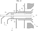
- JP 2 756 098 B2 discloses a pulverized coal burner 21 as illustrated in FIG. 21 .
- a pulverized coal supply pipe 29 having a curved tube section 25 and a straight tube section 22 for injecting a mixed fluid of a solid fuel and a carrier gas thereof, a liquid fuel injection pipe 28 is provided on a central axis of the straight tube section 22, a secondary air supply pipe 23 and a tertiary air supply pipe 24 are disposed around the pulverized coal supply pipe 29, and a secondary airflow and a tertiary airflow are supplied toward a furnace 13.
- the above patent discloses a configuration in which a pulverized coal concentration in a circumferential direction is made uniform by providing a swirl vane 26 downstream of the flow of the mixed fluid in the curved tube section 25, and a swirl strength of the flow is reduced by installing a swirl degree adjustment vane 27 in the vicinity of a burner outlet, as well as ignitability of flame of the pulverized coal is improved by making the mixed fluid close to a straight flow.
- GB 377 474 A discloses two swirlers provided inside of a fuel nozzle.
- the first swirler (vanes) is provided to apply swirl to fuel in the fuel nozzle to cause a powdered coal to whirl.
- the second swirler (vanes) is provided downstream in the flow direction of the fuel flow at an outlet (end portion) of the nozzle and reverses the powdered coal with gyratory motion before the powdered coal reaches the outlet of the nozzle.
- CN 101 832 551 A discloses two swirlers and an expander ring having an end-widening shape (conical) toward the furnace.
- One swirler is provided on a downstream side of the expander ring inside of a fuel nozzle.
- CN 101 832 551 A does not suggest to provide two swirlers in the flow direction of the fuel.
- the mixed fluid is dispersed in the furnace to secure ignitability and stability of the flame.
- this fluid is mixed with a combustion air such as a secondary air or tertiary air at an early stage, such that it is disadvantageous for reduction of nitrogen oxide (NOx).
- NOx nitrogen oxide
- pulverized coal ignites from a portion where a local concentration of the pulverized coal is high in a flow field of the mixed fluid, and the flame spreads around the portion. That is, in order to improve the ignitability of the pulverized coal, it is necessary to create a portion having a locally high concentration of pulverized coal in the flow field. This is particularly important for improving combustion stability at a low load in which an average concentration of the pulverized coal is low.
- the pulverized coal concentration in the mixed fluid is nonuniform to some extent, and a portion having a dense pulverized coal concentration is formed at an opening edge part of the burner (an end edge part of a fuel nozzle) or a flame stabilizer provided therein, so that the ignitability is increased, and stable combustion may be achieved even at a lower load.
- the primary object is to ensure the pulverized coal concentration in the circumferential direction is uniform, and in a case of a particularly low load, the pulverized coal concentration may fall below the ignition lower limit concentration equally in the circumferential direction. As a result, it is difficult to ignite the flame, and stable combustion may not be maintained.
- the adjustment vane of JP 2 756 098 B2 is a straightening plate in which a plurality of vanes are attached to an inner wall of the pipe so as to be substantially parallel to an axial center of the pulverized coal supply pipe. Accordingly, unless the length of the plate in the axial direction thereof is somewhat large, the action for reducing the swirl degree may not be obtained, which leads to an increase in a size of the vanes and, consequently, to an increase in a size of the burner. Further, since installation and attachment of the swirl vane and the adjustment vane require a large amount of labor and time, it is not preferable in terms of maintainability and installation costs.
- GB 377 474 A suggests to increase a swirling power at the outlet of the fuel nozzle such as the invention disclosed in JP H02 - 50 008 A .
- CN 101 832 551 A does not suggest to weaken a swirl strength of fluid at the outlet of the fuel nozzle, the solid fuel scatters to the outer peripheral side of the burner in the furnace. If this phenomenon occurs, stability of the flame is decreased and the emission amount of NOx is increased.
- the invention is a solid fuel burner (1) provided in a throat (13a) of a wall surface of a furnace (13), including: a fuel nozzle (9) which inter alia includes a straight tube section (2) provided around a burner central axis and having an opening toward the furnace (13) and a curved tube section (5) continued to the straight tube section (2), wherein a mixed fluid of a solid fuel and a carrier gas thereof supplied to the curved tube section (5) is sprayed from the opening of the straight tube section (2) to the furnace (13); a first swirler (6) which is provided in the straight tube section (2), and includes a plurality of vanes (6a) installed in the circumferential direction to apply a swirl to the mixed fluid; and a second swirler (7) which is provided downstream in a flow direction of the mixed fluid of the first swirler (6) in the straight tube section (2), includes a plurality of vanes (7a) disposed in the circumferential direction, and is installed in a direction reverse to a direction in which vanes (6a) of the first swirl
- a flame stabilizer (10) is provided on the outer periphery of the opening of the straight tube section (2).
- the first swirler (6) and the second swirler (7) are provided away from an inner wall of the fuel nozzle (9).
- the respective vanes (7a) of the second swirler (7) are installed so that an installation angle of the respective vanes (7a) of the second swirler (7) with respect to a burner central axis direction is equal to or smaller than the installation angle of the respective vanes (6a) of the first swirler (6) with respect to the burner central axis direction.
- a radial length of the respective vanes (7a) of the second swirler (7) is equal to or shorter than the radial length of respective vanes (6a) of the first swirler (6).
- a lateral width of respective vanes (7a) of the second swirler (7) is the same as or smaller than the lateral width of respective vanes (6a) of the first swirler (6).
- a disperser (14) for solid fuel particles is provided in the curved tube section (5).
- the disperser (14) is installed on a lateral face of an oil burner (8) provided on the burner central axis on a side facing a flow of the mixed fluid.
- the inventors considered increasing the fuel concentration in the vicinity of the flame stabilizer on the outer periphery of the outlet of the fuel nozzle by using a centrifugal effect due to the swirling flow of the mixed fluid.
- it is important to move the fuel flowing through the central part of the fuel nozzle to the outer peripheral side. Meanwhile, it is not necessary to move the fuel flowing on the outer peripheral side of the fuel nozzle (in the vicinity of the inner wall of the nozzle).
- the first swirling means is provided on the burner central axis side downstream of the curved tube section, and the fuel flowing through the central part of the burner is moved in the radial direction (to the outer peripheral side).
- the second swirling means for applying a swirl in the direction reverse to that of the first swirling means downstream in the flow direction of the mixed fluid of the first swirling means, the swirl strength may be reduced at once.
- the mixed fluid having the concentration distribution produced by the curved tube section is moved in the radial direction from the central axis by the first swirling means to increase the fuel concentration in the vicinity of the inner wall, and further the swirl strength may be reduced at once by applying a reverse swirl by the second swirling means. Accordingly, it is not necessary to secure the flow path length of the mixed fluid, and sizes of the fuel nozzle and the burner are not increased. Then, by weakening the swirling force of the mixed fluid, the ignitability in a fuel nozzle outlet is improved, and the stability of the flame is improved.
- the swirler by applying the swirl to the mixed fluid, in which the concentration distribution is produced by the curved tube section, by the first swirler, the fuel concentration in the vicinity of the inner wall is increased, and further by applying the reverse swirl by the second swirler, the swirl strength may be reduced at once. Furthermore, since the first swirler and the second swirler include the plurality of vanes installed in the circumferential direction, respectively, a simple configuration may be obtained, and these swirlers may be easily formed.
- the ignitability and the stability of the flame are further improved by the flame stabilizer provided in the fuel nozzle outlet, and an effect of improving the stability of the flame is high.
- the fuel flowing through the central part of the burner moves in the radial direction, but the mixed fluid in the vicinity of the inner wall of the fuel nozzle, which flows between an end part of the vane and the inner wall of the fuel nozzle, is minimally affected by the action of the swirl, and becomes a flow which goes straight ahead as it is toward the outlet. Accordingly, an action of weakening the swirl strength is also large, and it is possible to prevent the solid fuel in the vicinity of the inner wall from scattering to the outer periphery of the burner. In addition, it is easy to install and remove the vanes of the respective swirlers.
- the installation angle, the radial length of the respective vanes, the lateral width of the respective vanes, and the like of the respective vanes of the second swirler with respect to the burner central axis direction are set to be different from those of the respective vanes of the first swirler, such that the strength of the swirl may be changed.
- the installation angle of the respective vanes of the second swirler is set to be equal to or smaller than the installation angle of the respective vanes of the first swirler, such that it is possible to appropriately maintain the swirl strength in the fuel nozzle outlet without applying the strong reverse swirl to the mixed fluid.
- the radial length of the respective vanes of the second swirler is equal to or shorter than the radial length of the respective vanes of the first swirler, such that it is possible to appropriately maintain the swirl strength in the fuel nozzle outlet without applying the strong reverse swirl to the mixed fluid.
- the lateral width of the respective vanes of the second swirler is equal to or smaller than the lateral width of the respective vanes of the first swirler, such that it is possible to appropriately maintain the swirl strength in the fuel nozzle outlet without applying the strong reverse swirl to the mixed fluid.
- the centrifugal force acts on the mixed fluid by moving the mixed fluid via the curved tube section
- the solid fuel after passing through the curved tube section becomes a state of being biased in a direction on which the centrifugal force acts. Therefore, in accordance with the preferred aspect defined in claim 6, by providing the disperser of solid fuel particles in the curved tube section, a bias of the solid fuel particles in the mixed fluid is reduced.
- the disperser is installed on the lateral face of the oil burner provided on the burner central axis on the side facing the flow of the mixed fluid, such that the mixed fluid flows in the radial direction from the burner central axis in bypass manner after abutting the disperser.
- the solid fuel particles may be dispersed to the outer peripheral side of the fuel nozzle.
- the solid fuel burner of the present disclosure may improve the stability of the flame at the time of a low load in which the fuel concentration is low.
- the ignitability and the stability of the flame are improved. Further, since the first swirler and the second swirler have a simple configuration, these swirlers may be easily installed at a low cost without increasing the size of the burner.
- the ignitability and the stability of the flame in the fuel nozzle outlet are further improved by the flame stabilizer, and the effect of improving the stability of the flame is further enhanced.
- the solid fuel may be prevented from scattering to the outer periphery of the burner, thereby further improving the stability of the flame, and reducing a NOx emission amount.
- it is easy to install and remove the vanes of the respective swirlers, and maintainability is improved.
- the swirl strength may be appropriately maintained in the fuel nozzle outlet, and the ignitability and the stability of the flame are improved.
- the bias of the solid fuel particles is reduced by the disperser, such that the swirl effect on the downstream side may be more enhanced than ever before.
- the mixed fluid flows in the radial direction from the burner central axis and further in the circumferential direction by the disperser, such that the solid fuel particles are dispersed on the outer peripheral side of the fuel nozzle, and thereby stable combustion in the solid fuel burner may be achieved.
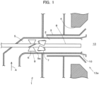
- FIG. 1 is a side view (schematic view) illustrating a partial cross-section of a solid fuel burner according to one example of the present disclosure.
- a solid fuel burner 1 provided in a throat 13a of a wall surface of a furnace 13 has a curved tube section 5 having a curved section of about 90° and a straight tube section 2 continued to the curved tube section 5, and includes a nozzle 9 having a circular cross-section for supplying a fuel, through which a mixed fluid of a finely powdered fuel and a carrier gas (solid-gas two-phase flow) flows.
- An oil burner 8 is provided on a central axis of the straight tube section 2.
- the solid fuel coal, biomass, or a mixture thereof may be used.
- the carrier gas of the solid fuel air is commonly used, but a mixed gas of a combustion exhaust gas and air may also be employed, and any type of the fuel and carrier gas may be used.
- pulverized coal is used as the solid fuel and air is used as the carrier gas, is illustrated, and the nozzle 9 for supplying a fuel is also referred to as a primary air nozzle 9.
- a tip of the straight tube section 2 is opened toward the furnace 13, and a mixed fluid of pulverized coal and the primary air supplied from a direction of an arrow A (lower side) to the primary air nozzle 9 passes through the curved tube section 5, and a direction thereof is changed by about 90°, then flows from the straight tube section 2 toward the furnace 13 and is sprayed from the opening (an outlet of the primary air nozzle 9).
- the curved tube section 5 may have a vertical cross-sectional shape of an L shape or a U shape, and may have a plurality of corners as illustrated in the drawing.
- an angle of the curved section of the curved tube section 5 is not limited to 90°, and it may be larger or smaller than 90°.
- an elbow pipe, a bend pipe or the like may be used as the curved tube section 5, an elbow pipe, a bend pipe or the like may be used.
- a secondary air nozzle 3 and a tertiary air nozzle 4 are disposed in a concentric pattern around the primary air nozzle 9, and secondary air and tertiary air are supplied toward the furnace 13. These air streams are sprayed so as to spread in an outer peripheral direction.
- a flame stabilizer (flame stabilization ring) 10 having an end-widening shape (conical) toward the furnace 13 side is provided around the outlet of the primary air nozzle 9 and between the primary air nozzle 9 and the secondary air nozzle 3.
- a burner with no flame stabilizer 10 installed therein is also included in the present embodiment.
- a circulation flow is formed on a downstream side (the furnace 13 side) of the flame stabilizer 10, and a mixture of the fuel and air sprayed from the primary air nozzle 9, the secondary air, a high-temperature combustion gas and the like flows into the circulation flow and remains therein.
- a temperature of the fuel particles rises due to radiant heat received from the furnace 13.
- the solid fuel ignites on the downstream side of the flame stabilizer 10, and the flame is maintained.
- An oil fuel is supplied from the tip of the oil burner 8 installed on the central axis of the primary air nozzle 9. The oil fuel is used to start up the solid fuel burner 1.
- air supplied to the secondary air nozzle 3 and the tertiary air nozzle 4 may be adjusted and controlled with a flow rate and a flow velocity of air by a flow rate adjustment member (such as a damper, air register, or the like) (not illustrated).
- a flow rate adjustment member such as a damper, air register, or the like
- the pulverized coal concentration is required to be set to a certain value or more when igniting the pulverized coal, it is particularly important to increase the fuel concentration in the vicinity of the flame stabilizer 10 at the time of a low load in which an average concentration of the pulverized coal is low.
- a first swirler 6 is provided at an entrance portion of the straight tube section 2 immediately after the curved tube section 5 and the central part of the primary air nozzle 9, and the pulverized coal flowing through the central part of the primary air nozzle 9 is moved to the outer peripheral side.
- the first swirler 6 includes a plurality of plate-shaped vanes 6a attached to an outer periphery of the oil burner 8. Further, in the region immediately after passing through the curved tube section 5, there is no need to apply a swirl to the mixed fluid flowing in the vicinity of the inner wall 9a of the primary air nozzle 9, such that an end part of the vane 6a is installed away from the inner wall 9a.
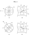
- FIG. 2 illustrates diagrams of the first swirler and the second swirler in FIG. 1 .
- FIGS. 2(A) and 2(C) illustrate front views, respectively
- FIG. 2(B) illustrates a view seen from S1 in FIG. 2(A)
- FIG. 2(D) illustrates a view seen from S2 in FIG. 2(C) .
- the respective swirlers 6 and 7 are installed so that the respective vanes 6a and 7a are not overlapped with each other as illustrated in FIGS. 2(A) and 2(C) , but it is not particularly limited to this arrangement.
- the direction of the vanes 7a of the second swirler 7 is reversed to the direction of the vanes 6a of the first swirler 6, such that the swirl strength of the mixed fluid at the outlet of the primary air nozzle 9 is weakened.
- the directions of the vanes 6a and the vanes 7a are reverse to each other, but the shapes and sizes of the respective vanes 6a and 7a are set to be all the same, and installation angles thereof with respect to the burner central axis direction of the respective vanes 6a and 7a are set to be the same as each other.
- the number of the respective vanes 6a and 7a is set to be four by four, but it may be larger or smaller than four, and it may be appropriately changed according to the size of the burner 1.
- both the vanes 6a and the vanes 7a are not necessarily provided on the burner central axis, but for the following reasons, it is preferable to provide these vanes on the burner central axis or install them away from the inner wall 9a.
- concentration distributions occur in the circumferential direction and the radial direction of the cylindrical nozzle cross-section. Then, the flow passing through a void between the vanes 6a of the first swirler 6 and the inner wall 9a among the mixed fluids, in which the concentration distribution has occurred, becomes a flow in such a manner that the concentration distribution produced in the circumferential direction is maintained toward the nozzle outlet.
- the mixed fluid flowing on the central axis side becomes a flow which is expanded toward the radial outside of the cylindrical nozzle cross-section on the downstream side thereof by the vanes 6a of the first swirler 6, so that the pulverized coal is condensed to the inner wall 9a side.
- the mixed fluid flowing in the vicinity of the inner wall 9a is subjected to some stirring effect by swirling, but it exhibits a tendency in which the concentration distribution produced in the circumferential direction is maintained toward the nozzle outlet, and further the pulverized coal concentration is increased.
- the swirling flow is weakened (or disappears) when viewing the cylindrical nozzle cross-section as a whole, but the pulverized coal concentration of the mixed fluid flowing in the vicinity of the nozzle inner wall 9a exhibits a tendency of being maintained to the nozzle outlet part (end edge part) due to an inertial force acting in the flowing direction of the pulverized coal particles.
- the mixed fluid flowing between the end parts of the respective vanes 6a and 7a and the inner wall 9a becomes a flow so as to be maintained toward the nozzle outlet, such that a high fuel concentration in the vicinity of the inner wall 9a may be maintained.
- the radial lengths of the respective vanes 6a and 7a are not particularly limited, it is desirable that the diameters of the vanes are set to be 50 to 75% of the inner diameter of the primary air nozzle 9. If the diameters of the respective vanes 6a and 7a are larger than 75%, the swirling component may easily remain in the fluid flowing on the outer peripheral side of the primary air nozzle 9. Further, if the diameters of the respective vanes 6a and 7a are too large, it is difficult to install and remove these vanes, and maintainability is deteriorated. Meanwhile, if the diameters of the respective vanes 6a and 7a are smaller than 50%, a concentration of particles to the outer peripheral side of the primary air nozzle 9 is insufficient.
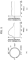
- FIG. 3(A) illustrates the particle concentration distribution in the radial direction of the burner 1 in FIG. 1
- FIG. 3(B) illustrates the particle concentration distribution in the radial direction of the burner used as a comparison.
- a fluid analysis by a k- ⁇ model was performed under a condition that the air and the pulverized coal flow at a rated load condition amount of the burner from the direction of an arrow A in FIG. 1 , and the concentration distribution of the pulverized coal particles at the outlet of the primary air nozzle 9 was calculated.
- the burner used as the comparison has a structure in which the swirler is not installed at all and the swirlers 6 and 7 are removed from the burner having the structure of FIG. 1 .
- An origin of the horizontal axis in each drawing is the central axis of the primary air nozzle 9, that is, an installation part of the oil burner 8, and it illustrates approaching the nozzle inner wall 9a with increasing the radial distance. That is, it illustrates that the distance in the radial direction from the central axis becomes larger according to the direction of the arrow (right direction) on the horizontal axis.
- the scales of the respective axes in FIGS. 3(A) and 3(B) are the same as each other.
- the pulverized coal concentration is an average in the circumferential direction of the concentration measured at a position where the radial distances are the same as each other. It illustrates that the concentration becomes higher according to the direction of the arrow (upper direction) on the vertical axis. It can also be seen from FIG. 3(A) that the pulverized coal concentration in the vicinity of the inner wall 9a is increased due to a swirling action by the first swirler 6 and the second swirler 7.
- the burner 21 of FIG. 21 is identical to the burner 1 of FIG. 1 in that the swirl vane 26 is provided in the pulverized coal supply pipe 29.
- a straightening plate 27 is installed at the burner outlet in order to weaken the swirling force.
- the swirl vane 26 is attached in contact with the inner wall 29a of the pulverized coal supply pipe 29, and there is no void between the swirl vane 26 and the inner wall 29a.
- the straightening plate 27 is attached to the inner wall 29a, and is installed away from the central axis.
- FIG. 4 illustrates swirl strength distributions in the vicinity of the burner outlets of the burner 1 in FIG. 1 and the burner of the comparative example.
- the fluid analysis by the k- ⁇ model was executed under a condition that the air and the pulverized coal flow at a rated load condition amount of the burner 1 and with a burner having the same structure as the burner of FIG. 1 , but with varied swirler shape and installation method, from the direction of the arrow A in FIG. 1 , similar to the case of FIG. 3 .
- the swirl strength distribution of the air at the burner outlet cross-section in the primary air nozzle 9 was calculated.
- numerical values of both the concentration distribution of the pulverized coal and the swirl strength distribution are calculated.
- the origin of FIG. 4 is the central axis of the primary air nozzle 9 (the installation part of the oil burner 8).
- the horizontal axis illustrates a radial distance from the central axis, and it illustrates approaching the inner wall 9a with increasing the radial distance.
- the swirl strength refers to a circumferential average value of the swirl strengths (a flow velocity component in a swirl direction (circumferential direction) to a flow velocity component in a main current direction (axial direction)), which are measured at the same radial distance as each other.
- a solid line B illustrates the swirl strength distribution of the burner 1 (in which the first swirler 6 and the second swirler 7 are installed away from the inner wall 9a) of FIG. 1
- a one-dot chain line C illustrates the swirl strength distribution of a case in which there is no second swirler 7 of the burner 1 of FIG. 1 (wherein the first swirler 6 is provided with being installed away from the inner wall 9a (Comparative Example 1)
- a broken line D illustrates the swirl strength distribution of a case in which the second swirler 7 of the burner 1 of FIG. 1 is not provided and the first swirler 6 is installed in contact with the inner wall 9a (Comparative Example 2).
- the particle concentration in the vicinity of the flame stabilizer 10 of the primary air nozzle 9 is increased.
- the pulverized coal particles moved to the outer peripheral side do not scatter to the outer periphery of the burner 1 in the furnace 13.
- FIGS. 5 and 6 illustrate the concentration distribution at the time of a high load in which the average concentration of pulverized coal is high
- FIG. 6 illustrates the concentration distribution at the time of a low load in which the average concentration of pulverized coal is low.
- the concentration distribution of the pulverized coal on the outermost peripheral side of the primary air nozzle 9 is illustrated along the circumferential direction. By setting the position on the left side to be 0°, the concentration was measured clockwise as viewed from the furnace 13, and the position was represented by an angle.
- FIGS. 5 illustrates the concentration distribution at the time of a high load in which the average concentration of pulverized coal is high
- FIG. 6 illustrates the concentration distribution at the time of a low load in which the average concentration of pulverized coal is low.
- the concentration distribution of the pulverized coal on the outermost peripheral side of the primary air nozzle 9 is illustrated along the circumferential direction. By setting the position on the left side to be 0°, the concentration was measured clockwise as viewed
- FIGS. 5B and 6B illustrate the concentration distribution of the pulverized coal in the burner 1 of FIG. 1
- FIGS. 5C and 6C illustrate the concentration distribution of the pulverized coal in the burner of the comparative example 2. It illustrates that the concentration of the pulverized coal on the vertical axis becomes higher according to the direction of the arrow (upper direction).
- the concentration distributions of the pulverized coal under the rated load condition amount of the burner of FIG. 1 and the burner of the comparative example 2 were calculated using the fluid analysis by the k- ⁇ model similar to the case of FIG. 3 .
- the particle concentration is substantially equal over the entire circumference. That is, since the vanes 6a of the first swirler 6 are in contact with the inner wall 9a, the swirling strength on the outer peripheral side of the primary air nozzle 9 is strong, and the pulverized coal on the outer peripheral side is agitated to be a uniform concentration. Accordingly, as illustrated in FIGS. 5(C) and 6(C) , there is no concentration change in the circumferential direction. Meanwhile, in the burner 1 of FIG. 1 , since the swirling force at the central part of the primary air nozzle 9 is strong, but swirl is not adequately applied to the outer peripheral part, the pulverized coal on the outer peripheral side is not agitated much. Therefore, in terms of the concentration distribution in the circumferential direction, there occurs portions with high and low pulverized coal concentrations, respectively.
- FIGS. 5 and 6 also illustrate an ignition lower limit concentration E.
- E ignition lower limit concentration
- the pulverized coal concentration exceeds the ignition lower limit concentration E.
- a flame is formed at the place, and the flame propagates around the place.
- both of the pulverized coal concentrations exceed the ignition lower limit concentration E, and there is no difference therebetween.
- the mixed fluid having the concentration distribution produced by the curved tube section 5 is moved outward in the radial direction from the central part by the first swirler 6 to increase the fuel concentration in the vicinity of the inner wall 9a, and a reverse swirl is applied thereto by the second swirler 7, such that the swirl strength may be reduced at once. Accordingly, even in the burner 1 without the flame stabilizer 10, if it is in the state that the fuel concentration in the vicinity of the inner wall 9a is high and the swirl strength is reduced, ignitability of the outlet of the primary air nozzle 9 is improved. In addition, it is not necessary to secure the flow path length of the mixed fluid, and the sizes of the primary air nozzle 9 and the burner 1 are not increased.
- the first swirler 6 and the second swirler 7 may be easily formed with a simple configuration that the respective vanes 6a and 7a are attached to the outer periphery of the oil burner 8. Further, by attaching the vanes 6a and 7a away from the inner wall 9a, the effect of improving the stability of the flame is also enhanced and stable combustion may be achieved. Furthermore, it is easy to install and remove the vanes 6a and 7a, and the maintainability is enhanced.
- FIG. 7 is a side view (schematic view) illustrating a partial cross-section of a solid fuel burner 1 according to another example of the present disclosure.
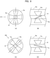
- FIG. 8 illustrates a first swirler and a second swirler in FIG. 7 , wherein FIGS. 8(A) and 8(C) are front views, respectively, FIG. 8(B) is a view seen from S1 in FIG. 8(A), and FIG. 8(D) is a view seen from S2 in FIG. 8(C) .
- the installation angle of the vanes 7a of the second swirler 7 with respect to the burner central axis direction is smaller than the installation angle of the vanes 6a of the first swirler 6, and the other configurations are the same as those of the solid fuel burner 1 according to Example 1.
- the installation angle of the vanes 7a of the second swirler 7 and the installation angle of the vanes 6a of the first swirler 6 are changed, the same effects as those of Example 1 are obtained.
- FIG. 9 is a side view (schematic view) illustrating a partial cross-section of a solid fuel burner 1 according to another example of the present disclosure.
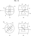
- FIG. 10 illustrates a first swirler and a second swirler in FIG. 9 , wherein FIGS. 10(A) and 10(C) are front views, respectively, FIG. 10(B) is a view seen from S1 in FIG. 10(A), and FIG. 10(D) is a view seen from S2 in FIG. 10(C) .
- the radial length of the vanes 7a of the second swirler 7 is set to be shorter than the radial length of the vanes 6a of the first swirler 6, thus to decrease the size as a whole.
- the other configurations are the same as those of the solid fuel burner 1 according to Example 1. Therefore, the installation angle and the shape of the vanes 6a and the vanes 7a are the same as those of Example 1. As such, even if the radial length of the vanes 7a of the second swirler 7 and the radial length of the vanes 6a of the first swirler 6 are changed, the same effects as those of Example 1 may be obtained.
- FIG. 11 is a side view (schematic view) illustrating a partial cross-section of a solid fuel burner 1 according to another example of the present disclosure.
- FIG. 12 illustrates a first swirler and a second swirler in FIG. 11 , wherein FIGS. 12(A) and 12(C) are front views, respectively, FIG. 12(B) is a view seen from S1 in FIG. 12(A), and FIG. 12(D) is a view seen from S2 in FIG. 12(C) .
- the lateral width of the vanes 7a of the second swirler 7 is set to be smaller than the lateral width of the vanes 6a of the first swirler 6, thus to have a narrow shape.
- the other configurations are the same as those of the solid fuel burner 1 according to Example 1. Therefore, the installation angle and the radial length of the vanes 6a and the vanes 7a are the same as those of Example 1. As such, even if the lateral width of the vanes 7a of the second swirler 7 and the lateral width of the vanes 6a of the first swirler 6 are changed, the same effects as those of Example 1 are obtained.
- FIG. 13 illustrates the swirl strength distributions in the vicinity of the burner outlet when the swirler is changed.
- the fluid analysis by the k- ⁇ model was executed under a condition that the air and the pulverized coal flow at a rated load condition amount of the burner from the direction of an arrow A in FIG. 1 similar to the case of FIG. 4 .
- a broken line F illustrates a case in which the diameters of the respective vanes 6a and 7a are set to be 75% of the inner diameter of the primary air nozzle 9, and the installation angle is set to be 30° on both the upstream side and the downstream side in the exhaust gas flow direction.
- a one-dotted chain line G illustrates a case in which the diameter of the vanes 6a on the upstream side is set to be 75% of the inner diameter of the primary air nozzle 9, the installation angle is set to be 45°, the diameter of the vanes 7a on the downstream side is set to be 75% of the inner diameter of the primary air nozzle 9, and the installation angle is set to be 25°.
- a solid line H illustrates a case in which the diameter of the vanes 6a on the upstream side is set to be 75% of the inner diameter of the primary air nozzle 9, the installation angle is set to be 30°, the diameter of the vanes 7a on the downstream side is set to be 50% of the inner diameter of the primary air nozzle 9, and the installation angle is set to be 45°.
- a broken line J illustrates a case in which the diameter of the vanes 6a on the upstream side is set to be 75% of the inner diameter of the primary air nozzle 9, the installation angle is set to be 30°, the diameter of the vanes 7a on the downstream side is set to be 75% of the inner diameter of the primary air nozzle 9, and the installation angle is set to be 45°.
- the lateral widths of the respective vanes 6a and 7a were the same as each other.
- the condition necessary for improving the stability of the flame and suppressing the NOx emission amount is that the swirl strength on the outermost peripheral side of the primary air nozzle 9 is minimized as much as possible. Since the pulverized coal concentration on the outermost peripheral side of the primary air nozzle 9 is high, if the swirling strength in this region is strong, the pulverized coal on the outermost peripheral side scatters around the burner 1, such that the stability of the flame is deteriorated, and the NOx concentration is increased. Meanwhile, since there is not much pulverized coal near the central part of the primary air nozzle 9, an influence applied to the combustion performance is small, even if the swirl strength at the central part is strong.
- the swirl strength at the central part of the primary air nozzle 9 is relatively large, but on the outer peripheral side of the primary air nozzle 9, the swirl strength becomes about zero.
- the swirl strength at the central part of the primary air nozzle 9 becomes small.
- the swirl strength on the outer peripheral side is slightly larger than the broken line F, but it is a small value.
- a case, in which the installation angle of the vanes 7a of the second swirler 7 is large, is indicated by a broken line J. In this case, the swirl strength is slightly increased also on the outer peripheral side of the primary air nozzle 9.
- Example 4 the swirl strength distribution in a case (Example 4), in which the lateral width of the vanes 7a of the second swirler 7 is decreased, and the other conditions are the same as those of the vanes 6a of the first swirler 6, it also becomes the swirl strength distribution similar to Example 2 (one-dot chain line G). Accordingly, from this fact, it can be seen that, as a difference between the cases in which the lateral width of the vane 7a of the second swirler 7 is small and large, there is the same difference of action as the magnitude of the installation angle and the diameter of the vanes 7a of the second swirler 7.
- vanes 7a of the second swirler 7 on the downstream side of the first swirler 6 satisfy the following conditions.
- first swirler 6 and the second swirler 7 there is no particular limitation on the installation position and interval of the first swirler 6 and the second swirler 7. This is common to all examples. For example, as illustrated in FIG. 14 , the first swirler 6 and the second swirler 7 may be installed away from each other as compared with other illustrated examples. Further, if the second swirler 7 is provided in the vicinity of the burner outlet, it is conceivable that a strong swirl component remains at the burner outlet, and the coal particles widely scatter in the furnace 13, and the NOx concentration is increased. Consequently and according to the invention it is foreseen to slightly separate the second swirler from the outlet.
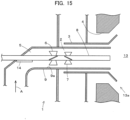
- FIG. 15 illustrates a side view illustrating a partial cross-section of a solid fuel burner according to another example of the present disclosure.
- FIG. 16(A) illustrates a perspective view of major parts (inside of the nozzle 9) in FIG. 15
- FIG. 16(B) illustrates a view of the major parts in FIG. 15
- FIG. 16(C) illustrates a cross-sectional view taken and seen on line A-A in FIG. 16(B)
- FIG. 16(D) illustrates a cross-sectional view taken and seen on line B-B in FIG. 16(B) .
- a solid fuel burner 1 of the present example is different from the solid fuel burner of the above-described respective examples in an aspect that a disperser 14 of pulverized coal particles is disposed on the upstream side of the first swirler 6 and in a space of the curved tube section 5 located on a root side of the oil burner 8, and the flame stabilizer 10 is not installed.
- the disperser 14 is a plate-shaped member having a plane part, and is attached to the lateral face of the oil burner 8 so that the plane part faces the upstream side of the curved section of the curved tube section 5.
- the plane part is directed to face the flow of the mixed fluid of the solid fuel and the carrier gas thereof introduced into the curved tube section 5.
- the first swirler 6 and the second swirler 7 are installed so that the respective vanes 6a and 7a are overlapped with each other as viewed from the furnace 13, but these swirlers may be disposed so as not to be overlapped with each other, as illustrated in Example 1 and the like.
- FIG. 17 is a schematic view illustrating a flow field of the mixed fluid of the burner 1 pursuant to FIG. 1 without the disperser 14, wherein FIG. 17(A) is a side view, and FIG. 17(B) is a front view.
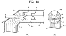
- FIG. 18 is a schematic view illustrating a flow field of the mixed fluid of the burner 1 in FIG. 15 provided with the disperser 14, wherein FIG. 18(A) is a side view, and FIG. 18(B) is a front view.
- FIGS. 17 and 18 illustrate a difference in the flow field of the mixed fluid depending on the presence or absence of the disperser 14.
- the mixed fluid supplied from the lower side of the curved tube section 5 moves via the curved tube section 5, such that the direction of the flow in the outlet direction of the straight tube section 2 (in the central axis direction of the primary air nozzle 9) is bent by about 90°.
- the centrifugal force acts on the mixed fluid when viewing the primary air nozzle 9 after passing through the curved tube section 5 as a cross-section, it becomes a state in which the pulverized coal is biased in the direction on which the centrifugal force acts.
- FIG. 6(B) shows the part in which the pulverized coal concentration in the vicinity of the inner wall 9a in an upper half of the primary air nozzle 9 is high.
- the flow field in a case in which the disperser 14 of FIG. 18 is provided will be described.
- the disperser 14 since the disperser 14 is disposed in the curved tube section 5, the disperser 14 becomes an obstacle when viewed from the mixed fluid supplied to the curved tube section 5. Thereby, the flow direction of the mixed fluid is changed in a direction (circumferential direction) bypassing the disperser 14.
- a part of the pulverized coal collides with the plane part of the disperser 14, and the concentration of the pulverized coal on the upper side (outside of the curved section) of the primary air nozzle 9 due to the centrifugal effect at the curved tube section 5 is mitigated.
- a flow line L2 there is an effect of enlarging a high concentration region of the pulverized coal in the circumferential direction on the nozzle outer peripheral side by the first swirler 6 and the second swirler 7.
- FIG. 19 illustrates the concentration distribution when the average pulverized coal concentration is low at the time of a low load. Similar to the case of FIG. 3 , the fluid analysis by the k- ⁇ model was executed.
- FIG. 19(B) is a diagram in which the concentration distribution (indicated by a one-dot chain line M) by the burner 1 of the present example is added to FIG. 6(B) , and FIG. 19(C) is the same as FIG. 6(C) .
- the state in which the pulverized coal concentration concentrates on the upper side of the primary air nozzle 9 by the disperser 14 is mitigated, and the high concentration region of the pulverized coal acts so as to be enlarged in the circumferential direction. Accordingly, even when the average pulverized coal concentration is low, the mixed fluid is dispersed to the outer peripheral side of the primary air nozzle 9, whereby the region in which the pulverized coal concentration exceeds the ignition lower limit concentration E becomes wide, and stable combustion of the burner may be achieved.
- FIG. 15 and the like illustrate the case in which the radial length of the vanes 7a of the second swirler 7 is set to be shorter than the radial length of the vanes 6a of the first swirler 6, but the respective vanes 6a and 7a of the first swirler 6 and the second swirler 7 may be the same as or different from each other in terms of the installation angle, the radial length, and the lateral width, and of course, these configurations belong within the scope of the present example.
- the flame stabilizer 10 may be installed in the burner 1 of FIG. 15 , and in this case, the effects of improving the stability of the flame and reducing the NOx emission amount are further enhanced.
- the present disclosure has industrial availability as a burner apparatus using a solid fuel.
Description
- The present disclosure relates to a solid fuel burner using coal, biomass, and the like as a fuel.
- In a combustion apparatus using a solid fuel, in order to achieve stable ignition and flame holding, supplying a mixed fluid (a mixed fluid of the fuel and a carrier gas thereof containing a sufficient concentration of fuel to a flame holding part of a burner outlet is required. As a conventional technology for concentrating the solid fuel inside the burner, there are
JP H02 - 50 008 A JP 2 756 098 B2 -
JP H02 - 50 008 A -
JP 2 756 098 B2 coal burner 21 as illustrated inFIG. 21 . In a pulverizedcoal supply pipe 29 having acurved tube section 25 and astraight tube section 22 for injecting a mixed fluid of a solid fuel and a carrier gas thereof, a liquidfuel injection pipe 28 is provided on a central axis of thestraight tube section 22, a secondaryair supply pipe 23 and a tertiaryair supply pipe 24 are disposed around the pulverizedcoal supply pipe 29, and a secondary airflow and a tertiary airflow are supplied toward afurnace 13. Further, the above patent discloses a configuration in which a pulverized coal concentration in a circumferential direction is made uniform by providing aswirl vane 26 downstream of the flow of the mixed fluid in thecurved tube section 25, and a swirl strength of the flow is reduced by installing a swirldegree adjustment vane 27 in the vicinity of a burner outlet, as well as ignitability of flame of the pulverized coal is improved by making the mixed fluid close to a straight flow. -
GB 377 474 A -
CN 101 832 551 A discloses two swirlers and an expander ring having an end-widening shape (conical) toward the furnace. One swirler is provided on a downstream side of the expander ring inside of a fuel nozzle. However,CN 101 832 551 A does not suggest to provide two swirlers in the flow direction of the fuel. - According to the configuration described in
JP H02 - 50 008 A - According to the configuration described in
JP 2 756 098 B2 - Meanwhile, pulverized coal ignites from a portion where a local concentration of the pulverized coal is high in a flow field of the mixed fluid, and the flame spreads around the portion. That is, in order to improve the ignitability of the pulverized coal, it is necessary to create a portion having a locally high concentration of pulverized coal in the flow field. This is particularly important for improving combustion stability at a low load in which an average concentration of the pulverized coal is low.
- Accordingly, it is better that the pulverized coal concentration in the mixed fluid is nonuniform to some extent, and a portion having a dense pulverized coal concentration is formed at an opening edge part of the burner (an end edge part of a fuel nozzle) or a flame stabilizer provided therein, so that the ignitability is increased, and stable combustion may be achieved even at a lower load.
- However, in
JP 2 756 098 B2 - Further, the adjustment vane of
JP 2 756 098 B2 -
GB 377 474 A JP H02 - 50 008 A - Since
CN 101 832 551 A does not suggest to weaken a swirl strength of fluid at the outlet of the fuel nozzle, the solid fuel scatters to the outer peripheral side of the burner in the furnace. If this phenomenon occurs, stability of the flame is decreased and the emission amount of NOx is increased. - It is an object of the present disclosure to provide a solid fuel burner which is superior in ignitability and flame stability, and is also superior in maintainability at a low cost even at the time of a low load with a low fuel concentration.
- The above object is achieved by providing a solid fuel burner with the features of
claim 1. - The invention is a solid fuel burner (1) provided in a throat (13a) of a wall surface of a furnace (13), including: a fuel nozzle (9) which inter alia includes a straight tube section (2) provided around a burner central axis and having an opening toward the furnace (13) and a curved tube section (5) continued to the straight tube section (2), wherein a mixed fluid of a solid fuel and a carrier gas thereof supplied to the curved tube section (5) is sprayed from the opening of the straight tube section (2) to the furnace (13); a first swirler (6) which is provided in the straight tube section (2), and includes a plurality of vanes (6a) installed in the circumferential direction to apply a swirl to the mixed fluid; and a second swirler (7) which is provided downstream in a flow direction of the mixed fluid of the first swirler (6) in the straight tube section (2), includes a plurality of vanes (7a) disposed in the circumferential direction, and is installed in a direction reverse to a direction in which vanes (6a) of the first swirler (6) are installed.
- Preferably, a flame stabilizer (10) is provided on the outer periphery of the opening of the straight tube section (2).
- According to the invention, the first swirler (6) and the second swirler (7) are provided away from an inner wall of the fuel nozzle (9).
- Preferably, the respective vanes (7a) of the second swirler (7) are installed so that an installation angle of the respective vanes (7a) of the second swirler (7) with respect to a burner central axis direction is equal to or smaller than the installation angle of the respective vanes (6a) of the first swirler (6) with respect to the burner central axis direction.
- Preferably, a radial length of the respective vanes (7a) of the second swirler (7) is equal to or shorter than the radial length of respective vanes (6a) of the first swirler (6).
- Preferably, a lateral width of respective vanes (7a) of the second swirler (7) is the same as or smaller than the lateral width of respective vanes (6a) of the first swirler (6).
- Preferably, a disperser (14) for solid fuel particles is provided in the curved tube section (5).
- Preferably, the disperser (14) is installed on a lateral face of an oil burner (8) provided on the burner central axis on a side facing a flow of the mixed fluid.
- In order to improve ignitability of the solid fuel such as pulverized coal, it is necessary to increase a fuel concentration in the vicinity of an outlet edge part of the burner or the flame stabilizer provided therein. By forming a vortex flow by the flame stabilizer, a flame to be a constantly burning pilot light is formed in the vicinity of the flame stabilizer, such that combustion of the fuel is promoted. The vortex flow promotes mixing of the solid fuel with the carrier gas, and is also a flow in the reverse direction, such that it has an action of facilitating the stability of the flame. Then, since it is necessary to set the fuel concentration to a certain value or more in order to ignite the fuel, it is particularly important to increase the fuel concentration in the vicinity of the outlet edge part of the burner and the flame stabilizer at the time of a low load in which the average fuel concentration is low.
- The inventors considered increasing the fuel concentration in the vicinity of the flame stabilizer on the outer periphery of the outlet of the fuel nozzle by using a centrifugal effect due to the swirling flow of the mixed fluid. In order to increase the fuel concentration in the vicinity of the flame stabilizer, it is important to move the fuel flowing through the central part of the fuel nozzle to the outer peripheral side. Meanwhile, it is not necessary to move the fuel flowing on the outer peripheral side of the fuel nozzle (in the vicinity of the inner wall of the nozzle).
- In the curved tube section at an inlet of the burner of the flow path through which the solid fuel passes, a concentration distribution from a region in which the solid fuel concentration is high to a region in which the solid fuel concentration is low may easily occur by a drift due to a centrifugal force. Therefore, the first swirling means is provided on the burner central axis side downstream of the curved tube section, and the fuel flowing through the central part of the burner is moved in the radial direction (to the outer peripheral side).
- Meanwhile, when a strong swirl is applied to the mixed fluid at the outlet of the fuel nozzle, the solid fuel scatters to the outer peripheral side of the burner in the furnace. If this phenomenon occurs, stability of the flame is decreased, and the emission amount of NOx is increased. Accordingly, it is necessary to weaken the swirl strength before the mixed fluid is sprayed into the furnace. Therefore, by providing the second swirling means for applying a swirl in the direction reverse to that of the first swirling means downstream in the flow direction of the mixed fluid of the first swirling means, the swirl strength may be reduced at once.
- That is, the mixed fluid having the concentration distribution produced by the curved tube section is moved in the radial direction from the central axis by the first swirling means to increase the fuel concentration in the vicinity of the inner wall, and further the swirl strength may be reduced at once by applying a reverse swirl by the second swirling means. Accordingly, it is not necessary to secure the flow path length of the mixed fluid, and sizes of the fuel nozzle and the burner are not increased. Then, by weakening the swirling force of the mixed fluid, the ignitability in a fuel nozzle outlet is improved, and the stability of the flame is improved.
- In addition, also in accordance with the invention, by applying the swirl to the mixed fluid, in which the concentration distribution is produced by the curved tube section, by the first swirler, the fuel concentration in the vicinity of the inner wall is increased, and further by applying the reverse swirl by the second swirler, the swirl strength may be reduced at once. Furthermore, since the first swirler and the second swirler include the plurality of vanes installed in the circumferential direction, respectively, a simple configuration may be obtained, and these swirlers may be easily formed.
- Further, in accordance with the inventions according to the preferred aspect defined in
claim 2, in addition to the actions of the invention, the ignitability and the stability of the flame are further improved by the flame stabilizer provided in the fuel nozzle outlet, and an effect of improving the stability of the flame is high. - In accordance with the invention preferred, by providing the first swirler and the second swirler away from the inner wall of the fuel nozzle, the fuel flowing through the central part of the burner moves in the radial direction, but the mixed fluid in the vicinity of the inner wall of the fuel nozzle, which flows between an end part of the vane and the inner wall of the fuel nozzle, is minimally affected by the action of the swirl, and becomes a flow which goes straight ahead as it is toward the outlet. Accordingly, an action of weakening the swirl strength is also large, and it is possible to prevent the solid fuel in the vicinity of the inner wall from scattering to the outer periphery of the burner. In addition, it is easy to install and remove the vanes of the respective swirlers.
- In addition, when applying a reverse swirl by the second swirler to the mixed fluid in which the swirl is applied by the first swirler, the installation angle, the radial length of the respective vanes, the lateral width of the respective vanes, and the like of the respective vanes of the second swirler with respect to the burner central axis direction are set to be different from those of the respective vanes of the first swirler, such that the strength of the swirl may be changed.
- When the installation angle of respective vanes of the second swirler is set to be larger than the installation angle of the respective vanes of the first swirler, when the radial length of respective vanes of the second swirler is set to be longer than the radial length of respective vanes of the first swirler, and when the lateral width of the respective vanes of the second swirler is set to be larger than the lateral width of the respective vanes of the first swirler, strong reverse swirls are applied not only to nearer the central axis but also to the mixed fluid on the outer peripheral side.
- Therefore, according to the preferred aspect defined in
claim 3, the installation angle of the respective vanes of the second swirler is set to be equal to or smaller than the installation angle of the respective vanes of the first swirler, such that it is possible to appropriately maintain the swirl strength in the fuel nozzle outlet without applying the strong reverse swirl to the mixed fluid. - In addition, in accordance with the preferred aspect defined in
claim 4, the radial length of the respective vanes of the second swirler is equal to or shorter than the radial length of the respective vanes of the first swirler, such that it is possible to appropriately maintain the swirl strength in the fuel nozzle outlet without applying the strong reverse swirl to the mixed fluid. - Further, in accordance with the preferred aspect defined in
claim 5, the lateral width of the respective vanes of the second swirler is equal to or smaller than the lateral width of the respective vanes of the first swirler, such that it is possible to appropriately maintain the swirl strength in the fuel nozzle outlet without applying the strong reverse swirl to the mixed fluid. - Further, since the centrifugal force acts on the mixed fluid by moving the mixed fluid via the curved tube section, the solid fuel after passing through the curved tube section becomes a state of being biased in a direction on which the centrifugal force acts. Therefore, in accordance with the preferred aspect defined in
claim 6, by providing the disperser of solid fuel particles in the curved tube section, a bias of the solid fuel particles in the mixed fluid is reduced. - Further, in accordance with the preferred aspect defined in
claim 7, the disperser is installed on the lateral face of the oil burner provided on the burner central axis on the side facing the flow of the mixed fluid, such that the mixed fluid flows in the radial direction from the burner central axis in bypass manner after abutting the disperser. Thereby, the solid fuel particles may be dispersed to the outer peripheral side of the fuel nozzle. - The solid fuel burner of the present disclosure may improve the stability of the flame at the time of a low load in which the fuel concentration is low.
- In accordance with the invention, by increasing the fuel concentration in the vicinity of the inner wall and weakening the swirling force of the mixed fluid at the fuel nozzle outlet, the ignitability and the stability of the flame are improved. Further, since the first swirler and the second swirler have a simple configuration, these swirlers may be easily installed at a low cost without increasing the size of the burner.
- Further, in accordance with the preferred aspect defined in
claim 2, the ignitability and the stability of the flame in the fuel nozzle outlet are further improved by the flame stabilizer, and the effect of improving the stability of the flame is further enhanced. - Further, in accordance with the invention, the solid fuel may be prevented from scattering to the outer periphery of the burner, thereby further improving the stability of the flame, and reducing a NOx emission amount. In addition, it is easy to install and remove the vanes of the respective swirlers, and maintainability is improved.
- In accordance with the preferred aspects defined in
claims 3 to 5, the swirl strength may be appropriately maintained in the fuel nozzle outlet, and the ignitability and the stability of the flame are improved. - In accordance with the preferred aspect defined in
claim 6, the bias of the solid fuel particles is reduced by the disperser, such that the swirl effect on the downstream side may be more enhanced than ever before. - In accordance with the preferred aspect defined in
claim 7, the mixed fluid flows in the radial direction from the burner central axis and further in the circumferential direction by the disperser, such that the solid fuel particles are dispersed on the outer peripheral side of the fuel nozzle, and thereby stable combustion in the solid fuel burner may be achieved. -
-
FIG. 1 is a side view illustrating a partial cross-section of a solid fuel burner which is one example (Example 1) of the present disclosure. -
FIG. 2(A) is a front view of a first swirler inFIG. 1 (view seen from a furnace side),FIG. 2(B) is a view seen from S1 inFIG. 2(A), FIG. 2(C) is a front view of a second swirler inFIG. 1 , andFIG. 2(D) is a view seen from S2 inFIG. 2(C) . -
FIG. 3(A) is a diagram illustrating a particle concentration distribution in a radial direction of the burner of Example 1, andFIG. 3(B) is a diagram illustrating the particle concentration distribution in the radial direction of a burner used as a comparison. -
FIG. 4 is a diagram illustrating swirl strength distributions in the vicinity of burner outlets of the burner of Example 1 and the burner of the comparative example. -
FIG. 5 is diagrams comparing circumferential concentration distributions on outlet outer peripheral sides of the burner of Example 1 and the burner of the comparative example at the time of a high load. -
FIG. 6 is diagrams comparing the circumferential concentration distributions on the outlet outer peripheral sides of the burner of Example 1 and the burner of the comparative example at the time of a low load. -
FIG. 7 is a side view illustrating a partial cross-section of a solid fuel burner which is another example (Example 2) of the present disclosure. -
FIG. 8(A) is a front view of a first swirler inFIG. 7 ,FIG. 8(B) is a view seen from S1 inFIG. 8(A), FIG. 8(C) is a front view of a second swirler inFIG. 7 , andFIG. 8(D) is a view seen from S2 inFIG. 8(C) . -
FIG. 9 is a side view illustrating a partial cross-section of a solid fuel burner which is another example (Example 3) of the present disclosure. -
FIG. 10(A) is a front view of a first swirler inFIG. 9 ,FIG. 10(B) is a view seen from S1 inFIG. 10(A), FIG. 10(C) is a front view of a second swirler inFIG. 9 , andFIG. 10(D) is a view seen from S2 inFIG. 10(C) . -
FIG. 11 is a side view illustrating a partial cross-section of a solid fuel burner which is another example (Example 4) of the present disclosure. -
FIG. 12(A) is a front view of a first swirler inFIG. 11 ,FIG. 12(B) is a view seen from S1 inFIG. 12(A), FIG. 12(C) is a front view of a second swirler inFIG. 11 , andFIG. 12(D) is a view seen from S2 inFIG. 12(C) . -
FIG. 13 is a diagram illustrating the swirl strength distribution in the vicinity of the burner outlet when the swirler is changed. -
FIG. 14 is a side view illustrating a partial cross-section of a solid fuel burner which is another example of the present disclosure. -
FIG. 15 is a side view illustrating a partial cross-section of a solid fuel burner which is another example (Example 5) of the present disclosure. -
FIG. 16(A) is a perspective view of major parts inFIG. 15 ,FIG. 16(B) is an enlarged view of the major parts inFIG. 15 ,FIG. 16(C) is a cross-sectional view taken and seen on line A-A inFIG. 16(B), and FIG. 16(D) is a cross-sectional view taken and seen on line B-B inFIG. 16(B) . -
FIG. 17 is a view illustrating a flow field of a mixed fluid when a particle disperser is not provided, whereinFIG. 17(A) is a side view, andFIG. 17(B) is a front view. -
FIG. 18 is a view illustrating a flow field of a mixed fluid when a particle disperser is provided, whereinFIG. 18(A) is a side view, andFIG. 18(B) is a front view. -
FIG. 19 is diagrams comparing the circumferential concentration distributions on outlet outer peripheral sides of the burner of Example 5 and the burner of the comparative example at the time of a low load. -
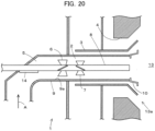
FIG. 20 is a side view illustrating a partial cross-section of a solid fuel burner which is another example (Example 5) of the present disclosure. -
FIG. 21 is a side view illustrating a partial cross-section of a conventional solid fuel burner. - Hereinafter, embodiments of the present disclosure will be described.
-
FIG. 1 is a side view (schematic view) illustrating a partial cross-section of a solid fuel burner according to one example of the present disclosure. - A
solid fuel burner 1 provided in athroat 13a of a wall surface of afurnace 13 has acurved tube section 5 having a curved section of about 90° and astraight tube section 2 continued to thecurved tube section 5, and includes anozzle 9 having a circular cross-section for supplying a fuel, through which a mixed fluid of a finely powdered fuel and a carrier gas (solid-gas two-phase flow) flows. Anoil burner 8 is provided on a central axis of thestraight tube section 2. - Further, as the solid fuel, coal, biomass, or a mixture thereof may be used. In addition, as the carrier gas of the solid fuel, air is commonly used, but a mixed gas of a combustion exhaust gas and air may also be employed, and any type of the fuel and carrier gas may be used. In the present embodiment, an example, in which pulverized coal is used as the solid fuel and air is used as the carrier gas, is illustrated, and the
nozzle 9 for supplying a fuel is also referred to as aprimary air nozzle 9. - A tip of the
straight tube section 2 is opened toward thefurnace 13, and a mixed fluid of pulverized coal and the primary air supplied from a direction of an arrow A (lower side) to theprimary air nozzle 9 passes through thecurved tube section 5, and a direction thereof is changed by about 90°, then flows from thestraight tube section 2 toward thefurnace 13 and is sprayed from the opening (an outlet of the primary air nozzle 9). Thecurved tube section 5 may have a vertical cross-sectional shape of an L shape or a U shape, and may have a plurality of corners as illustrated in the drawing. In addition, an angle of the curved section of thecurved tube section 5 is not limited to 90°, and it may be larger or smaller than 90°. As thecurved tube section 5, an elbow pipe, a bend pipe or the like may be used. - Further, a
secondary air nozzle 3 and atertiary air nozzle 4 are disposed in a concentric pattern around theprimary air nozzle 9, and secondary air and tertiary air are supplied toward thefurnace 13. These air streams are sprayed so as to spread in an outer peripheral direction. Further, a flame stabilizer (flame stabilization ring) 10 having an end-widening shape (conical) toward thefurnace 13 side is provided around the outlet of theprimary air nozzle 9 and between theprimary air nozzle 9 and thesecondary air nozzle 3. Further, a burner with noflame stabilizer 10 installed therein is also included in the present embodiment. - A circulation flow is formed on a downstream side (the
furnace 13 side) of theflame stabilizer 10, and a mixture of the fuel and air sprayed from theprimary air nozzle 9, the secondary air, a high-temperature combustion gas and the like flows into the circulation flow and remains therein. In addition, a temperature of the fuel particles rises due to radiant heat received from thefurnace 13. With these effects, the solid fuel ignites on the downstream side of theflame stabilizer 10, and the flame is maintained. An oil fuel is supplied from the tip of theoil burner 8 installed on the central axis of theprimary air nozzle 9. The oil fuel is used to start up thesolid fuel burner 1. - In addition, air supplied to the
secondary air nozzle 3 and thetertiary air nozzle 4 may be adjusted and controlled with a flow rate and a flow velocity of air by a flow rate adjustment member (such as a damper, air register, or the like) (not illustrated). - In order to improve ignitability of the pulverized coal, it is necessary to increase a fuel concentration in the vicinity of the
flame stabilizer 10 at the burner outlet. Since the pulverized coal concentration is required to be set to a certain value or more when igniting the pulverized coal, it is particularly important to increase the fuel concentration in the vicinity of theflame stabilizer 10 at the time of a low load in which an average concentration of the pulverized coal is low. - Therefore, by applying a swirl to the mixed fluid, it becomes possible to increase the fuel concentration in the vicinity of the
flame stabilizer 10 due to its centrifugal effect. For that purpose, it is important to move the pulverized coal flowing around theoil burner 8 at the central part of the primary air nozzle 9 (on the central axis side of the cylindrical nozzle cross-section) to an outer peripheral side (radially outside, in the vicinity of theinner wall 9a). Meanwhile, there is no need to move the pulverized coal flowing in the vicinity of theinner wall 9a of theprimary air nozzle 9. - Therefore, a
first swirler 6 is provided at an entrance portion of thestraight tube section 2 immediately after thecurved tube section 5 and the central part of theprimary air nozzle 9, and the pulverized coal flowing through the central part of theprimary air nozzle 9 is moved to the outer peripheral side. Thefirst swirler 6 includes a plurality of plate-shapedvanes 6a attached to an outer periphery of theoil burner 8. Further, in the region immediately after passing through thecurved tube section 5, there is no need to apply a swirl to the mixed fluid flowing in the vicinity of theinner wall 9a of theprimary air nozzle 9, such that an end part of thevane 6a is installed away from theinner wall 9a. - If the swirl is strongly applied to the mixed fluid at the outlet of the
primary air nozzle 9, the pulverized coal particles splatter to the outer peripheral side of thesolid fuel burner 1 within thefurnace 13, such that stability of the flame is decreased, and a NOx emission amount is increased as described above. Accordingly, it is necessary to weaken the swirl strength before the mixed fluid is sprayed into thefurnace 13. In the present embodiment, as asecond swirler 7 on the downstream side of thefirst swirler 6, similar to thefirst swirler 6, a plurality of plate-shapedvanes 7a are attached to the outer periphery of theoil burner 8. Theseswirlers -
FIG. 2 illustrates diagrams of the first swirler and the second swirler inFIG. 1 .FIGS. 2(A) and 2(C) illustrate front views, respectively,FIG. 2(B) illustrates a view seen from S1 inFIG. 2(A), and FIG. 2(D) illustrates a view seen from S2 inFIG. 2(C) . Further, in order to reduce the number of particles that can pass through theswirlers swirlers furnace 13, the respective swirlers 6 and 7 are installed so that therespective vanes FIGS. 2(A) and 2(C) , but it is not particularly limited to this arrangement. - As illustrated in
FIG. 2 , the direction of thevanes 7a of thesecond swirler 7 is reversed to the direction of thevanes 6a of thefirst swirler 6, such that the swirl strength of the mixed fluid at the outlet of theprimary air nozzle 9 is weakened. - In the example of
FIG. 1 , the directions of thevanes 6a and thevanes 7a (the direction of the swirl around the central axis) are reverse to each other, but the shapes and sizes of therespective vanes respective vanes respective vanes burner 1. In addition, although it is not always necessary to equally provide therespective vanes - Further, if the directions of the
vanes 6a and thevanes 7a are reverse to each other, the shapes, sizes, installation angles, and the like of thevanes 6a andvanes 7a may be different from each other. In addition, both thevanes 6a and thevanes 7a are not necessarily provided on the burner central axis, but for the following reasons, it is preferable to provide these vanes on the burner central axis or install them away from theinner wall 9a. - As the mixed fluid passes through the
curved tube section 5, concentration distributions occur in the circumferential direction and the radial direction of the cylindrical nozzle cross-section. Then, the flow passing through a void between thevanes 6a of thefirst swirler 6 and theinner wall 9a among the mixed fluids, in which the concentration distribution has occurred, becomes a flow in such a manner that the concentration distribution produced in the circumferential direction is maintained toward the nozzle outlet. - Meanwhile, the mixed fluid flowing on the central axis side becomes a flow which is expanded toward the radial outside of the cylindrical nozzle cross-section on the downstream side thereof by the
vanes 6a of thefirst swirler 6, so that the pulverized coal is condensed to theinner wall 9a side. - For this reason, as a result of overlapping the above two flows with each other, the mixed fluid flowing in the vicinity of the
inner wall 9a is subjected to some stirring effect by swirling, but it exhibits a tendency in which the concentration distribution produced in the circumferential direction is maintained toward the nozzle outlet, and further the pulverized coal concentration is increased. - Herein, on the downstream side of the
second swirler 7, due to the action of thevanes 7a, the swirling flow is weakened (or disappears) when viewing the cylindrical nozzle cross-section as a whole, but the pulverized coal concentration of the mixed fluid flowing in the vicinity of the nozzleinner wall 9a exhibits a tendency of being maintained to the nozzle outlet part (end edge part) due to an inertial force acting in the flowing direction of the pulverized coal particles. - As illustrated in
FIG. 2 , by installing thevanes 6a and thevanes 7a away from theinner wall 9a, the mixed fluid flowing between the end parts of therespective vanes inner wall 9a becomes a flow so as to be maintained toward the nozzle outlet, such that a high fuel concentration in the vicinity of theinner wall 9a may be maintained. - Although the radial lengths of the
respective vanes primary air nozzle 9. If the diameters of therespective vanes primary air nozzle 9. Further, if the diameters of therespective vanes respective vanes primary air nozzle 9 is insufficient. -
FIG. 3(A) illustrates the particle concentration distribution in the radial direction of theburner 1 inFIG. 1 , andFIG. 3(B) illustrates the particle concentration distribution in the radial direction of the burner used as a comparison. A fluid analysis by a k-ε model was performed under a condition that the air and the pulverized coal flow at a rated load condition amount of the burner from the direction of an arrow A inFIG. 1 , and the concentration distribution of the pulverized coal particles at the outlet of theprimary air nozzle 9 was calculated. - Further, the burner used as the comparison has a structure in which the swirler is not installed at all and the swirlers 6 and 7 are removed from the burner having the structure of
FIG. 1 . An origin of the horizontal axis in each drawing is the central axis of theprimary air nozzle 9, that is, an installation part of theoil burner 8, and it illustrates approaching the nozzleinner wall 9a with increasing the radial distance. That is, it illustrates that the distance in the radial direction from the central axis becomes larger according to the direction of the arrow (right direction) on the horizontal axis. The scales of the respective axes inFIGS. 3(A) and 3(B) are the same as each other. The pulverized coal concentration is an average in the circumferential direction of the concentration measured at a position where the radial distances are the same as each other. It illustrates that the concentration becomes higher according to the direction of the arrow (upper direction) on the vertical axis. It can also be seen fromFIG. 3(A) that the pulverized coal concentration in the vicinity of theinner wall 9a is increased due to a swirling action by thefirst swirler 6 and thesecond swirler 7. - In order to compare with the
burner 21 ofFIG. 21 , the effect of the present example was further verified. - The
burner 21 ofFIG. 21 is identical to theburner 1 ofFIG. 1 in that theswirl vane 26 is provided in the pulverizedcoal supply pipe 29. In addition, a straighteningplate 27 is installed at the burner outlet in order to weaken the swirling force. However, in theburner 21 ofFIG. 21 , theswirl vane 26 is attached in contact with theinner wall 29a of the pulverizedcoal supply pipe 29, and there is no void between theswirl vane 26 and theinner wall 29a. Similarly, the straighteningplate 27 is attached to theinner wall 29a, and is installed away from the central axis. -
FIG. 4 illustrates swirl strength distributions in the vicinity of the burner outlets of theburner 1 inFIG. 1 and the burner of the comparative example. The fluid analysis by the k-ε model was executed under a condition that the air and the pulverized coal flow at a rated load condition amount of theburner 1 and with a burner having the same structure as the burner ofFIG. 1 , but with varied swirler shape and installation method, from the direction of the arrow A inFIG. 1 , similar to the case ofFIG. 3 . Then, the swirl strength distribution of the air at the burner outlet cross-section in theprimary air nozzle 9 was calculated. In this fluid analysis, numerical values of both the concentration distribution of the pulverized coal and the swirl strength distribution are calculated. - The origin of
FIG. 4 is the central axis of the primary air nozzle 9 (the installation part of the oil burner 8). The horizontal axis illustrates a radial distance from the central axis, and it illustrates approaching theinner wall 9a with increasing the radial distance. In the present specification, the swirl strength refers to a circumferential average value of the swirl strengths (a flow velocity component in a swirl direction (circumferential direction) to a flow velocity component in a main current direction (axial direction)), which are measured at the same radial distance as each other. - Since there are clockwise and counterclockwise in the swirl direction as viewed from the
furnace 13, two axes (vertical axis) are illustrated inFIG. 4 so that the direction of swirl may be determined. A solid line B illustrates the swirl strength distribution of the burner 1 (in which thefirst swirler 6 and thesecond swirler 7 are installed away from theinner wall 9a) ofFIG. 1 , a one-dot chain line C illustrates the swirl strength distribution of a case in which there is nosecond swirler 7 of theburner 1 ofFIG. 1 (wherein thefirst swirler 6 is provided with being installed away from theinner wall 9a (Comparative Example 1), and a broken line D illustrates the swirl strength distribution of a case in which thesecond swirler 7 of theburner 1 ofFIG. 1 is not provided and thefirst swirler 6 is installed in contact with theinner wall 9a (Comparative Example 2). - In Comparative Example 1 (one-dot chain line C), the swirl strength of the
primary air nozzle 9 at the central part (origin side) was strong, but the swirl strength on the outer peripheral side of theprimary air nozzle 9 was weakened. The reason is that thevanes 6a of thefirst swirler 6 are installed only in the central part of theprimary air nozzle 9. However, it can be said that the swirl strength thereof on the outer peripheral side is comparatively strong. - Meanwhile, in a case in which two
swirlers vanes primary air nozzle 9 moves to the outer peripheral side. - Thereby, the particle concentration in the vicinity of the
flame stabilizer 10 of theprimary air nozzle 9 is increased. In addition, since swirl is not applied to the outer peripheral side of theprimary air nozzle 9, the pulverized coal particles moved to the outer peripheral side do not scatter to the outer periphery of theburner 1 in thefurnace 13. - On the other hand, in Comparative Example 2 (broken line D), a strong swirl is applied to the outer peripheral side of the
primary air nozzle 9. Since the swirl is also applied to the central part of theprimary air nozzle 9, there is an effect of increasing the particle concentration in the vicinity of theflame stabilizer 10 of theprimary air nozzle 9. However, since the swirl strength on the outer peripheral side of theprimary air nozzle 9 is strong, it becomes difficult to adjust the swirl strength at the burner outlet. Accordingly, also in theburner 21 illustrated inFIG. 21 , since theswirl vane 26 and the straighteningplate 27 are in contact with theinner wall 29a of the pulverizedcoal supply pipe 29, it can be said that the same problem occurs. - Next, the concentration distribution of the pulverized coal is calculated, then the effect of the present example is further verified, and the results thereof are illustrated in
FIGS. 5 and6 .FIG. 5 illustrates the concentration distribution at the time of a high load in which the average concentration of pulverized coal is high, andFIG. 6 illustrates the concentration distribution at the time of a low load in which the average concentration of pulverized coal is low. As illustrated inFIGS. 5(A) and6(A) , the concentration distribution of the pulverized coal on the outermost peripheral side of theprimary air nozzle 9 is illustrated along the circumferential direction. By setting the position on the left side to be 0°, the concentration was measured clockwise as viewed from thefurnace 13, and the position was represented by an angle.FIGS. 5B and6B illustrate the concentration distribution of the pulverized coal in theburner 1 ofFIG. 1 , andFIGS. 5C and6C illustrate the concentration distribution of the pulverized coal in the burner of the comparative example 2. It illustrates that the concentration of the pulverized coal on the vertical axis becomes higher according to the direction of the arrow (upper direction). - The concentration distributions of the pulverized coal under the rated load condition amount of the burner of
FIG. 1 and the burner of the comparative example 2 were calculated using the fluid analysis by the k-ε model similar to the case ofFIG. 3 . - In these burners, since the pulverized coal is concentrated due to a centrifugal effect at the
curved tube section 5, there is tendency of easily increasing the pulverized coal concentration on the upper side (outside the curved section). - In the case of Comparative Example 2, the particle concentration is substantially equal over the entire circumference. That is, since the
vanes 6a of thefirst swirler 6 are in contact with theinner wall 9a, the swirling strength on the outer peripheral side of theprimary air nozzle 9 is strong, and the pulverized coal on the outer peripheral side is agitated to be a uniform concentration. Accordingly, as illustrated inFIGS. 5(C) and6(C) , there is no concentration change in the circumferential direction. Meanwhile, in theburner 1 ofFIG. 1 , since the swirling force at the central part of theprimary air nozzle 9 is strong, but swirl is not adequately applied to the outer peripheral part, the pulverized coal on the outer peripheral side is not agitated much. Therefore, in terms of the concentration distribution in the circumferential direction, there occurs portions with high and low pulverized coal concentrations, respectively. -
FIGS. 5 and6 also illustrate an ignition lower limit concentration E. In order to achieve stable combustion in the burner, it is necessary for at least a part of the pulverized coal concentration to exceed the ignition lower limit concentration E. When there is a place where the pulverized coal concentration exceeds the ignition lower limit concentration E, a flame is formed at the place, and the flame propagates around the place. Under conditions in which the load is high and the average pulverized coal concentration is also high, as illustrated inFIGS. 5(B) and 5(C) , both of the pulverized coal concentrations exceed the ignition lower limit concentration E, and there is no difference therebetween. - When the load is low, and the average pulverized coal concentration is also low, in Comparative Example 2, as illustrated in
FIG. 6(C) , there is no place where the pulverized coal concentration is locally high, and the pulverized coal concentration in all regions becomes below the lower limit concentration E, such that stable combustion is not achieved. Further, it is not necessary for the pulverized coal concentration to exceed the ignition lower limit concentration E in all positions, and as illustrated inFIG. 6(B) , there is a region in which the pulverized coal concentration is locally high. If the concentration exceeds the ignition lower limit concentration E, it is possible to achieve the stable combustion even under a low load condition. - From the above description, according to the present example, the mixed fluid having the concentration distribution produced by the
curved tube section 5 is moved outward in the radial direction from the central part by thefirst swirler 6 to increase the fuel concentration in the vicinity of theinner wall 9a, and a reverse swirl is applied thereto by thesecond swirler 7, such that the swirl strength may be reduced at once. Accordingly, even in theburner 1 without theflame stabilizer 10, if it is in the state that the fuel concentration in the vicinity of theinner wall 9a is high and the swirl strength is reduced, ignitability of the outlet of theprimary air nozzle 9 is improved. In addition, it is not necessary to secure the flow path length of the mixed fluid, and the sizes of theprimary air nozzle 9 and theburner 1 are not increased. - Further, by providing the
flame stabilizer 10 in the outlet of theprimary air nozzle 9, the ignitability and the stability of the flame are further improved, and effects of improving the stability of the flame and reducing the NOx emission amount are further enhanced. In addition, thefirst swirler 6 and thesecond swirler 7 may be easily formed with a simple configuration that therespective vanes oil burner 8. Further, by attaching thevanes inner wall 9a, the effect of improving the stability of the flame is also enhanced and stable combustion may be achieved. Furthermore, it is easy to install and remove thevanes -
FIG. 7 is a side view (schematic view) illustrating a partial cross-section of asolid fuel burner 1 according to another example of the present disclosure.FIG. 8 illustrates a first swirler and a second swirler inFIG. 7 , whereinFIGS. 8(A) and 8(C) are front views, respectively,FIG. 8(B) is a view seen from S1 inFIG. 8(A), and FIG. 8(D) is a view seen from S2 inFIG. 8(C) . - In the present example, the installation angle of the
vanes 7a of thesecond swirler 7 with respect to the burner central axis direction is smaller than the installation angle of thevanes 6a of thefirst swirler 6, and the other configurations are the same as those of thesolid fuel burner 1 according to Example 1. As such, even if the installation angle of thevanes 7a of thesecond swirler 7 and the installation angle of thevanes 6a of thefirst swirler 6 are changed, the same effects as those of Example 1 are obtained. - Further, since there is no particular limitation on the positions of the axial direction of the
first swirler 6 and thesecond swirler 7, various examples are illustrated. In particular, there is no difference in action and effect. These are the same as the other examples. -
FIG. 9 is a side view (schematic view) illustrating a partial cross-section of asolid fuel burner 1 according to another example of the present disclosure.FIG. 10 illustrates a first swirler and a second swirler inFIG. 9 , whereinFIGS. 10(A) and 10(C) are front views, respectively,FIG. 10(B) is a view seen from S1 inFIG. 10(A), and FIG. 10(D) is a view seen from S2 inFIG. 10(C) . - In the present example, the radial length of the
vanes 7a of thesecond swirler 7 is set to be shorter than the radial length of thevanes 6a of thefirst swirler 6, thus to decrease the size as a whole. The other configurations are the same as those of thesolid fuel burner 1 according to Example 1. Therefore, the installation angle and the shape of thevanes 6a and thevanes 7a are the same as those of Example 1. As such, even if the radial length of thevanes 7a of thesecond swirler 7 and the radial length of thevanes 6a of thefirst swirler 6 are changed, the same effects as those of Example 1 may be obtained. -
FIG. 11 is a side view (schematic view) illustrating a partial cross-section of asolid fuel burner 1 according to another example of the present disclosure.FIG. 12 illustrates a first swirler and a second swirler inFIG. 11 , whereinFIGS. 12(A) and 12(C) are front views, respectively,FIG. 12(B) is a view seen from S1 inFIG. 12(A), and FIG. 12(D) is a view seen from S2 inFIG. 12(C) . - In the present example, the lateral width of the
vanes 7a of thesecond swirler 7 is set to be smaller than the lateral width of thevanes 6a of thefirst swirler 6, thus to have a narrow shape. The other configurations are the same as those of thesolid fuel burner 1 according to Example 1. Therefore, the installation angle and the radial length of thevanes 6a and thevanes 7a are the same as those of Example 1. As such, even if the lateral width of thevanes 7a of thesecond swirler 7 and the lateral width of thevanes 6a of thefirst swirler 6 are changed, the same effects as those of Example 1 are obtained. - Hereinafter, the results of further intensive verification performed by changing three conditions of the installation angle, the radial length, and the lateral width of the
respective vanes first swirler 6 and thesecond swirler 7 are illustrated.FIG. 13 illustrates the swirl strength distributions in the vicinity of the burner outlet when the swirler is changed. The fluid analysis by the k-ε model was executed under a condition that the air and the pulverized coal flow at a rated load condition amount of the burner from the direction of an arrow A inFIG. 1 similar to the case ofFIG. 4 . - A broken line F illustrates a case in which the diameters of the
respective vanes primary air nozzle 9, and the installation angle is set to be 30° on both the upstream side and the downstream side in the exhaust gas flow direction. A one-dotted chain line G illustrates a case in which the diameter of thevanes 6a on the upstream side is set to be 75% of the inner diameter of theprimary air nozzle 9, the installation angle is set to be 45°, the diameter of thevanes 7a on the downstream side is set to be 75% of the inner diameter of theprimary air nozzle 9, and the installation angle is set to be 25°. A solid line H illustrates a case in which the diameter of thevanes 6a on the upstream side is set to be 75% of the inner diameter of theprimary air nozzle 9, the installation angle is set to be 30°, the diameter of thevanes 7a on the downstream side is set to be 50% of the inner diameter of theprimary air nozzle 9, and the installation angle is set to be 45°. A broken line J illustrates a case in which the diameter of thevanes 6a on the upstream side is set to be 75% of the inner diameter of theprimary air nozzle 9, the installation angle is set to be 30°, the diameter of thevanes 7a on the downstream side is set to be 75% of the inner diameter of theprimary air nozzle 9, and the installation angle is set to be 45°. The lateral widths of therespective vanes - Similar to the case of
FIG. 4 , the swirl strength distribution of the air at the burner outlet cross-section in theprimary air nozzle 9 was calculated. - The condition necessary for improving the stability of the flame and suppressing the NOx emission amount is that the swirl strength on the outermost peripheral side of the
primary air nozzle 9 is minimized as much as possible. Since the pulverized coal concentration on the outermost peripheral side of theprimary air nozzle 9 is high, if the swirling strength in this region is strong, the pulverized coal on the outermost peripheral side scatters around theburner 1, such that the stability of the flame is deteriorated, and the NOx concentration is increased. Meanwhile, since there is not much pulverized coal near the central part of theprimary air nozzle 9, an influence applied to the combustion performance is small, even if the swirl strength at the central part is strong. - In the broken line F (Example 1), the swirl strength at the central part of the
primary air nozzle 9 is relatively large, but on the outer peripheral side of theprimary air nozzle 9, the swirl strength becomes about zero. In addition, in the one-dotted chain line G (Example 2), the swirl strength at the central part of theprimary air nozzle 9 becomes small. The swirl strength on the outer peripheral side is slightly larger than the broken line F, but it is a small value. Meanwhile, a case, in which the installation angle of thevanes 7a of thesecond swirler 7 is large, is indicated by a broken line J. In this case, the swirl strength is slightly increased also on the outer peripheral side of theprimary air nozzle 9. - However, as illustrated by the solid line H, even if the installation angle of the
vanes 7a of thesecond swirler 7 is large, when the diameter of thevanes 7a is small, it becomes to the swirl strength distribution similar to the one-dot chain line G. Further, when the average value of the swirl strength is taken over the entire region from the central part to the outer peripheral part, it becomes substantially zero. - Further, although not illustrated, the swirl strength distribution in a case (Example 4), in which the lateral width of the
vanes 7a of thesecond swirler 7 is decreased, and the other conditions are the same as those of thevanes 6a of thefirst swirler 6, it also becomes the swirl strength distribution similar to Example 2 (one-dot chain line G). Accordingly, from this fact, it can be seen that, as a difference between the cases in which the lateral width of thevane 7a of thesecond swirler 7 is small and large, there is the same difference of action as the magnitude of the installation angle and the diameter of thevanes 7a of thesecond swirler 7. - From the above description, it is preferable that the
vanes 7a of thesecond swirler 7 on the downstream side of thefirst swirler 6 satisfy the following conditions. - (1) The radial length of the
vanes 7a is equal to or smaller than the radial length of thevanes 6a of thefirst swirler 6. - (2) The installation angle of the
vanes 7a is equal to or smaller than the installation angle of thevanes 6a. - (3) The lateral width of the
vanes 7a is equal to or smaller than the lateral width of thevanes 6a. - In addition, there is no particular limitation on the installation position and interval of the
first swirler 6 and thesecond swirler 7. This is common to all examples. For example, as illustrated inFIG. 14 , thefirst swirler 6 and thesecond swirler 7 may be installed away from each other as compared with other illustrated examples. Further, if thesecond swirler 7 is provided in the vicinity of the burner outlet, it is conceivable that a strong swirl component remains at the burner outlet, and the coal particles widely scatter in thefurnace 13, and the NOx concentration is increased. Consequently and according to the invention it is foreseen to slightly separate the second swirler from the outlet. -
FIG. 15 illustrates a side view illustrating a partial cross-section of a solid fuel burner according to another example of the present disclosure.FIG. 16(A) illustrates a perspective view of major parts (inside of the nozzle 9) inFIG. 15 ,FIG. 16(B) illustrates a view of the major parts inFIG. 15 ,FIG. 16(C) illustrates a cross-sectional view taken and seen on line A-A inFIG. 16(B), and FIG. 16(D) illustrates a cross-sectional view taken and seen on line B-B inFIG. 16(B) . - A
solid fuel burner 1 of the present example is different from the solid fuel burner of the above-described respective examples in an aspect that adisperser 14 of pulverized coal particles is disposed on the upstream side of thefirst swirler 6 and in a space of thecurved tube section 5 located on a root side of theoil burner 8, and theflame stabilizer 10 is not installed. Specifically, as illustrated inFIG. 16 , thedisperser 14 is a plate-shaped member having a plane part, and is attached to the lateral face of theoil burner 8 so that the plane part faces the upstream side of the curved section of thecurved tube section 5. - That is, the plane part is directed to face the flow of the mixed fluid of the solid fuel and the carrier gas thereof introduced into the
curved tube section 5. In addition, thefirst swirler 6 and thesecond swirler 7 are installed so that therespective vanes furnace 13, but these swirlers may be disposed so as not to be overlapped with each other, as illustrated in Example 1 and the like. -
FIG. 17 is a schematic view illustrating a flow field of the mixed fluid of theburner 1 pursuant toFIG. 1 without thedisperser 14, whereinFIG. 17(A) is a side view, andFIG. 17(B) is a front view.FIG. 18 is a schematic view illustrating a flow field of the mixed fluid of theburner 1 inFIG. 15 provided with thedisperser 14, whereinFIG. 18(A) is a side view, andFIG. 18(B) is a front view. -
FIGS. 17 and18 illustrate a difference in the flow field of the mixed fluid depending on the presence or absence of thedisperser 14. First, the flow field in a case in which thedisperser 14 ofFIG. 17 is not provided will be described. The mixed fluid supplied from the lower side of thecurved tube section 5 moves via thecurved tube section 5, such that the direction of the flow in the outlet direction of the straight tube section 2 (in the central axis direction of the primary air nozzle 9) is bent by about 90°. At this time, since the centrifugal force acts on the mixed fluid, when viewing theprimary air nozzle 9 after passing through thecurved tube section 5 as a cross-section, it becomes a state in which the pulverized coal is biased in the direction on which the centrifugal force acts. In the illustrated example, it shows the part in which the pulverized coal concentration in the vicinity of theinner wall 9a in an upper half of theprimary air nozzle 9 is high. Even in this case, by applying the above-describedfirst swirler 6 and thesecond swirler 7, it is possible to form a state in which the pulverized coal concentration exceeds the ignition lower limit concentration E (FIG. 6(B) even when the average pulverized coal concentration is low such as at the time of a low load or the like, but from the viewpoint of stable combustion of the burner, it is desirable to further enlarge the region in which the pulverized coal concentration exceeds the ignition lower limit concentration E. - Next, the flow field in a case in which the
disperser 14 ofFIG. 18 is provided will be described. In the present example, since thedisperser 14 is disposed in thecurved tube section 5, thedisperser 14 becomes an obstacle when viewed from the mixed fluid supplied to thecurved tube section 5. Thereby, the flow direction of the mixed fluid is changed in a direction (circumferential direction) bypassing thedisperser 14. In addition, a part of the pulverized coal collides with the plane part of thedisperser 14, and the concentration of the pulverized coal on the upper side (outside of the curved section) of theprimary air nozzle 9 due to the centrifugal effect at thecurved tube section 5 is mitigated. As a result, like a flow line L2, there is an effect of enlarging a high concentration region of the pulverized coal in the circumferential direction on the nozzle outer peripheral side by thefirst swirler 6 and thesecond swirler 7. -
FIG. 19 illustrates the concentration distribution when the average pulverized coal concentration is low at the time of a low load. Similar to the case ofFIG. 3 , the fluid analysis by the k-ε model was executed.FIG. 19(B) is a diagram in which the concentration distribution (indicated by a one-dot chain line M) by theburner 1 of the present example is added toFIG. 6(B) , andFIG. 19(C) is the same asFIG. 6(C) . - According to the present example, the state in which the pulverized coal concentration concentrates on the upper side of the
primary air nozzle 9 by thedisperser 14 is mitigated, and the high concentration region of the pulverized coal acts so as to be enlarged in the circumferential direction. Accordingly, even when the average pulverized coal concentration is low, the mixed fluid is dispersed to the outer peripheral side of theprimary air nozzle 9, whereby the region in which the pulverized coal concentration exceeds the ignition lower limit concentration E becomes wide, and stable combustion of the burner may be achieved. - In addition,
FIG. 15 and the like illustrate the case in which the radial length of thevanes 7a of thesecond swirler 7 is set to be shorter than the radial length of thevanes 6a of thefirst swirler 6, but therespective vanes first swirler 6 and thesecond swirler 7 may be the same as or different from each other in terms of the installation angle, the radial length, and the lateral width, and of course, these configurations belong within the scope of the present example. In addition, as illustrated inFIG. 20 , theflame stabilizer 10 may be installed in theburner 1 ofFIG. 15 , and in this case, the effects of improving the stability of the flame and reducing the NOx emission amount are further enhanced. - The present disclosure has industrial availability as a burner apparatus using a solid fuel.
- Description of Reference Numerals
- 1, 21
- solid fuel burner
- 2, 22
- straight tube section
- 3
- secondary air nozzle
- 4
- tertiary air nozzle
- 5, 25
- curved tube section
- 6
- first swirler
- 7
- second swirler
- 8
- oil burner
- 9
- primary air nozzle
- 10
- flame stabilizer
- 13
- furnace
- 14
- particle disperser
- 23
- secondary air supply pipe
- 24
- tertiary air supply pipe
- 26
- swirl vane
- 27
- adjustment vane (straightening plate)
- 28
- liquid fuel injection pipe
- 29
- pulverized coal supply pipe
Claims (7)
- A solid fuel burner (1) configured to be provided in a throat (13a) of a wall surface of a furnace (13), comprising:a fuel nozzle (9) which includes a straight tube section (2) provided around a burner central axis and having a circular cross section and an opening toward the furnace (13), and a curved tube section (5) continued to the straight tube section (2), wherein the fuel nozzle (9) is configured such that a mixed fluid of a solid fuel and a carrier gas thereof supplied to the curved tube section (5) is sprayed from the opening of the straight tube section (2) to the furnace (13) at an outlet of the fuel nozzle (9);a first swirler (6) which is provided in the straight tube section (2), and includes a plurality of vanes (6a) installed in the circumferential direction to apply a swirl to the mixed fluid; anda second swirler (7) which is provided downstream in a flow direction of the mixed fluid of the first swirler (6) in the straight tube section (2), includes a plurality of vanes (7a) disposed in the circumferential direction, and is installed in a direction reverse to a direction in which the vanes (6a) of the first swirler (6) are installed,wherein the first swirler (6) and the second swirler (7) are provided away from an inner wall of the fuel nozzle (9), andwherein the second swirler (7) is slightly separated from the outlet of the fuel nozzle (9) so that a strong swirl component remaining at the burner outlet does not remain.
- The solid fuel burner (1) according to claim 1, wherein a flame stabilizer (10) is provided on the outer periphery of the opening of the straight tube section (2).
- The solid fuel burner (1) according to claim 1 or 2, wherein respective vanes (7a) of the second swirler (7) are installed so that an installation angle of the respective vanes (7a) of the second swirler (7) with respect to a burner central axis direction is equal to or smaller than the installation angle of the respective vanes (6a) of the first swirler (6) with respect to the burner central axis direction.
- The solid fuel burner (1) according to claim 1 or 2, wherein a radial length of the respective vanes (7a) of the second swirler (7) is equal to or shorter than the radial length of respective vanes (6a) of the first swirler (6).
- The solid fuel burner (1) according to claim 1 or 2, wherein a lateral width of respective vanes (7a) of the second swirler (7) is the same as or smaller than the lateral width of respective vanes (6a) of the first swirler (6).
- The solid fuel burner (1) according to any one of claims 1 to 5, wherein a disperser (14) for solid fuel particles is provided in the curved tube section (5).
- The solid fuel burner (1) according to claim 6, wherein the disperser (14) is installed on a lateral face of an oil burner (8) provided on the burner central axis on a side facing a flow of the mixed fluid.
Applications Claiming Priority (2)
| Application Number | Priority Date | Filing Date | Title |
|---|---|---|---|
| JP2015131146A JP6231047B2 (en) | 2015-06-30 | 2015-06-30 | Solid fuel burner |
| PCT/JP2016/068469 WO2017002675A1 (en) | 2015-06-30 | 2016-06-22 | Solid fuel burner |
Publications (3)
| Publication Number | Publication Date |
|---|---|
| EP3318801A1 EP3318801A1 (en) | 2018-05-09 |
| EP3318801A4 EP3318801A4 (en) | 2019-01-09 |
| EP3318801B1 true EP3318801B1 (en) | 2023-08-30 |
Family
ID=57608185
Family Applications (1)
| Application Number | Title | Priority Date | Filing Date |
|---|---|---|---|
| EP16817783.0A Active EP3318801B1 (en) | 2015-06-30 | 2016-06-22 | Solid fuel burner |
Country Status (12)
| Country | Link |
|---|---|
| US (1) | US10731850B2 (en) |
| EP (1) | EP3318801B1 (en) |
| JP (1) | JP6231047B2 (en) |
| KR (1) | KR101962583B1 (en) |
| CN (1) | CN108351100B (en) |
| AU (1) | AU2016286769B2 (en) |
| FI (1) | FI3318801T3 (en) |
| MY (1) | MY186833A (en) |
| PH (1) | PH12017502377B1 (en) |
| PL (1) | PL3318801T3 (en) |
| TW (1) | TWI618893B (en) |
| WO (1) | WO2017002675A1 (en) |
Families Citing this family (9)
| Publication number | Priority date | Publication date | Assignee | Title |
|---|---|---|---|---|
| CN107120645B (en) * | 2017-03-24 | 2019-04-09 | 浙江大学 | A kind of spray cyclone burner with acoustic damping pipe and position adjustable rotary flow table |
| CN107355781A (en) * | 2017-08-30 | 2017-11-17 | 山西煜能科技开发有限公司 | A kind of methanol burner flame vortex device |
| JP7171276B2 (en) * | 2018-07-09 | 2022-11-15 | 三菱重工業株式会社 | solid fuel burner |
| JP2020030037A (en) * | 2018-08-20 | 2020-02-27 | 三菱日立パワーシステムズ株式会社 | Solid fuel burner |
| WO2020152867A1 (en) * | 2019-01-25 | 2020-07-30 | 三菱日立パワーシステムズ株式会社 | Solid fuel burner and combustion device |
| WO2020178880A1 (en) | 2019-03-01 | 2020-09-10 | 三菱日立パワーシステムズ株式会社 | Solid fuel burner |
| JP7429501B2 (en) * | 2019-04-10 | 2024-02-08 | 株式会社Ihi | powder injection device |
| TW202336384A (en) * | 2021-12-24 | 2023-09-16 | 日商三菱重工業股份有限公司 | Burner, boiler equipped with same, and method for operating burner |
| CN114992631B (en) * | 2022-05-25 | 2023-04-11 | 河南凯盛石油设备有限公司 | Double-channel decomposing furnace burner |
Family Cites Families (39)
| Publication number | Priority date | Publication date | Assignee | Title |
|---|---|---|---|---|
| GB303226A (en) * | 1927-10-15 | 1929-01-03 | Henry Adam Procter | Improvements in or relating to the burning of pulverised fuel |
| GB377474A (en) * | 1930-12-17 | 1932-07-28 | Hanrez Sa J Atel | Improvements in or relating to process and burner for the combustion of powdered coal |
| US2793686A (en) * | 1952-03-18 | 1957-05-28 | Rubye W Phillips | Axially adjustable fuel burner for furnaces |
| JPS6026922B2 (en) * | 1980-02-25 | 1985-06-26 | 川崎重工業株式会社 | pulverized coal burner |
| US4464108A (en) * | 1980-11-21 | 1984-08-07 | Donald Korenyi | Combustion apparatus |
| US4412810A (en) * | 1981-03-04 | 1983-11-01 | Kawasaki Jukogyo Kabushiki Kaisha | Pulverized coal burner |
| US4422391A (en) * | 1981-03-12 | 1983-12-27 | Kawasaki Jukogyo Kabushiki Kaisha | Method of combustion of pulverized coal by pulverized coal burner |
| CA1186951A (en) * | 1981-12-23 | 1985-05-14 | Daniel C. Itse | Venturi burner nozzle for pulverized coal |
| US4457241A (en) | 1981-12-23 | 1984-07-03 | Riley Stoker Corporation | Method of burning pulverized coal |
| US4479442A (en) | 1981-12-23 | 1984-10-30 | Riley Stoker Corporation | Venturi burner nozzle for pulverized coal |
| JPS58224208A (en) * | 1982-06-19 | 1983-12-26 | Babcock Hitachi Kk | Uniform dispersion type pulverized coal firing equipment |
| US4654001A (en) * | 1986-01-27 | 1987-03-31 | The Babcock & Wilcox Company | Flame stabilizing/NOx reduction device for pulverized coal burner |
| JP2519923B2 (en) * | 1987-04-28 | 1996-07-31 | バブコツク日立株式会社 | Pulverized coal combustion equipment |
| DE68912401T2 (en) * | 1988-03-04 | 1994-06-23 | Northern Eng Ind | Burner for dusty fuel. |
| JPH0250008A (en) | 1988-08-08 | 1990-02-20 | Babcock Hitachi Kk | Pulverized coal burner |
| CA2151308C (en) * | 1994-06-17 | 1999-06-08 | Hideaki Ohta | Pulverized fuel combustion burner |
| JP3140299B2 (en) * | 1994-06-30 | 2001-03-05 | 株式会社日立製作所 | Pulverized coal burner and its use |
| US5529000A (en) * | 1994-08-08 | 1996-06-25 | Combustion Components Associates, Inc. | Pulverized coal and air flow spreader |
| JP3518626B2 (en) * | 1994-11-28 | 2004-04-12 | バブコック日立株式会社 | Pulverized coal combustion equipment |
| JP2756098B2 (en) * | 1995-07-14 | 1998-05-25 | 川崎重工業株式会社 | Pulverized coal burner |
| DE19527083A1 (en) * | 1995-07-25 | 1997-01-30 | Lentjes Kraftwerkstechnik | Process and burner for reducing NO¶x¶ formation from coal dust combustion |
| JP3099109B2 (en) * | 1996-05-24 | 2000-10-16 | 株式会社日立製作所 | Pulverized coal burner |
| EP0836049B1 (en) * | 1996-10-08 | 2001-12-12 | Ansaldo Caldaie S.P.A. | Pulverized coal injection nozzle |
| JP3344694B2 (en) * | 1997-07-24 | 2002-11-11 | 株式会社日立製作所 | Pulverized coal combustion burner |
| KR100372146B1 (en) * | 1999-11-20 | 2003-02-14 | 두산중공업 주식회사 | Pulverized coal burner for reducing NOx |
| US6986311B2 (en) * | 2003-01-22 | 2006-01-17 | Joel Vatsky | Burner system and method for mixing a plurality of solid fuels |
| US20090061374A1 (en) * | 2007-01-17 | 2009-03-05 | De Jong Johannes Cornelis | High capacity burner |
| US8082860B2 (en) * | 2008-04-30 | 2011-12-27 | Babcock Power Services Inc. | Anti-roping device for pulverized coal burners |
| US9151434B2 (en) * | 2008-12-18 | 2015-10-06 | Alstom Technology Ltd | Coal rope distributor with replaceable wear components |
| US9151493B2 (en) | 2008-12-18 | 2015-10-06 | Alstom Technology Ltd | Coal rope distributor with replaceable wear components |
| US9857077B2 (en) | 2008-12-18 | 2018-01-02 | General Electric Technology Gmbh | Coal rope distributor with replaceable wear components |
| GB0919964D0 (en) * | 2009-11-16 | 2009-12-30 | Doosan Babcock Energy Ltd | Flow control device |
| CN101832551A (en) * | 2010-06-18 | 2010-09-15 | 上海交通大学 | Adjustable center weak swirl pulverized coal burner |
| US10820610B2 (en) | 2011-12-19 | 2020-11-03 | Deinove | Ingredients for animal feed compositions |
| JP5886031B2 (en) * | 2011-12-26 | 2016-03-16 | 川崎重工業株式会社 | Biomass fuel combustion method |
| JP5897363B2 (en) | 2012-03-21 | 2016-03-30 | 川崎重工業株式会社 | Pulverized coal biomass mixed burner |
| JP5897364B2 (en) * | 2012-03-21 | 2016-03-30 | 川崎重工業株式会社 | Pulverized coal biomass mixed burner |
| DE102012007884A1 (en) * | 2012-04-23 | 2013-10-24 | Babcock Borsig Steinmüller Gmbh | Burner for dust and / or particulate fuels with variable swirl |
| CN103759258B (en) * | 2014-01-13 | 2016-06-15 | 徐州科融环境资源股份有限公司 | A kind of joint low nitrogen vortex burner of oil/gas ignition smooth combustion |
-
2015
- 2015-06-30 JP JP2015131146A patent/JP6231047B2/en active Active
-
2016
- 2016-06-22 US US15/740,482 patent/US10731850B2/en active Active
- 2016-06-22 EP EP16817783.0A patent/EP3318801B1/en active Active
- 2016-06-22 PL PL16817783.0T patent/PL3318801T3/en unknown
- 2016-06-22 KR KR1020187002743A patent/KR101962583B1/en active IP Right Grant
- 2016-06-22 CN CN201680039136.0A patent/CN108351100B/en active Active
- 2016-06-22 FI FIEP16817783.0T patent/FI3318801T3/en active
- 2016-06-22 AU AU2016286769A patent/AU2016286769B2/en active Active
- 2016-06-22 WO PCT/JP2016/068469 patent/WO2017002675A1/en active Application Filing
- 2016-06-22 MY MYPI2017704871A patent/MY186833A/en unknown
- 2016-06-28 TW TW105120313A patent/TWI618893B/en active
-
2017
- 2017-12-20 PH PH12017502377A patent/PH12017502377B1/en unknown
Also Published As
| Publication number | Publication date |
|---|---|
| AU2016286769A1 (en) | 2018-02-01 |
| EP3318801A1 (en) | 2018-05-09 |
| EP3318801A4 (en) | 2019-01-09 |
| US10731850B2 (en) | 2020-08-04 |
| US20180195716A1 (en) | 2018-07-12 |
| CN108351100A (en) | 2018-07-31 |
| KR20180022909A (en) | 2018-03-06 |
| PH12017502377A1 (en) | 2018-06-25 |
| JP6231047B2 (en) | 2017-11-15 |
| JP2017015305A (en) | 2017-01-19 |
| CN108351100B (en) | 2020-03-13 |
| KR101962583B1 (en) | 2019-07-17 |
| FI3318801T3 (en) | 2023-10-16 |
| AU2016286769B2 (en) | 2018-12-06 |
| MY186833A (en) | 2021-08-25 |
| WO2017002675A1 (en) | 2017-01-05 |
| TWI618893B (en) | 2018-03-21 |
| PH12017502377B1 (en) | 2018-06-25 |
| TW201716728A (en) | 2017-05-16 |
| PL3318801T3 (en) | 2024-02-26 |
Similar Documents
| Publication | Publication Date | Title |
|---|---|---|
| EP3318801B1 (en) | Solid fuel burner | |
| EP2515039B1 (en) | Solid fuel burner and solid fuel boiler | |
| WO2018034286A1 (en) | Solid fuel burner | |
| US7553153B2 (en) | Burner and combustion method for solid fuels | |
| JP2010270992A (en) | Coal burning boiler | |
| JP2018028418A5 (en) | ||
| JP6084138B2 (en) | Premix burner | |
| JP5386230B2 (en) | Fuel burner and swirl combustion boiler | |
| JPH0926112A (en) | Pulverized coal burner | |
| JP2010270991A (en) | Coal burning boiler | |
| AU2019216590B2 (en) | Solid fuel burner | |
| JP5797238B2 (en) | Fuel burner and swirl combustion boiler | |
| JP2016521840A (en) | Asymmetric baseplate cooling with alternating swivel main burner | |
| KR102405991B1 (en) | Flamesheet combustor contoured liner | |
| US11519600B2 (en) | Solid fuel burner and flame stabilizer for solid fuel burner | |
| JP5799443B2 (en) | Fuel burner, solid fuel fired burner, and solid fuel fired boiler | |
| JP5629901B2 (en) | Solid fuel fired burner and solid fuel fired boiler | |
| JP2010270990A (en) | Fuel burner and turning combustion boiler | |
| WO2016179822A1 (en) | A system for burning pulverized solid fuel and a method thereof | |
| JPS6280413A (en) | Low nox combustion device for solid fuel | |
| JPS6237606A (en) | Solid fuel burning device with low nox concentration |
Legal Events
| Date | Code | Title | Description |
|---|---|---|---|
| STAA | Information on the status of an ep patent application or granted ep patent |
Free format text: STATUS: THE INTERNATIONAL PUBLICATION HAS BEEN MADE |
|
| PUAI | Public reference made under article 153(3) epc to a published international application that has entered the european phase |
Free format text: ORIGINAL CODE: 0009012 |
|
| STAA | Information on the status of an ep patent application or granted ep patent |
Free format text: STATUS: REQUEST FOR EXAMINATION WAS MADE |
|
| 17P | Request for examination filed |
Effective date: 20180124 |
|
| AK | Designated contracting states |
Kind code of ref document: A1 Designated state(s): AL AT BE BG CH CY CZ DE DK EE ES FI FR GB GR HR HU IE IS IT LI LT LU LV MC MK MT NL NO PL PT RO RS SE SI SK SM TR |
|
| AX | Request for extension of the european patent |
Extension state: BA ME |
|
| DAV | Request for validation of the european patent (deleted) | ||
| DAX | Request for extension of the european patent (deleted) | ||
| A4 | Supplementary search report drawn up and despatched |
Effective date: 20181207 |
|
| RIC1 | Information provided on ipc code assigned before grant |
Ipc: F23D 1/00 20060101AFI20181203BHEP |
|
| STAA | Information on the status of an ep patent application or granted ep patent |
Free format text: STATUS: EXAMINATION IS IN PROGRESS |
|
| STAA | Information on the status of an ep patent application or granted ep patent |
Free format text: STATUS: EXAMINATION IS IN PROGRESS |
|
| 17Q | First examination report despatched |
Effective date: 20201216 |
|
| RAP3 | Party data changed (applicant data changed or rights of an application transferred) |
Owner name: MITSUBISHI POWER, LTD. |
|
| STAA | Information on the status of an ep patent application or granted ep patent |
Free format text: STATUS: EXAMINATION IS IN PROGRESS |
|
| RAP1 | Party data changed (applicant data changed or rights of an application transferred) |
Owner name: MITSUBISHI HEAVY INDUSTRIES, LTD. |
|
| GRAP | Despatch of communication of intention to grant a patent |
Free format text: ORIGINAL CODE: EPIDOSNIGR1 |
|
| STAA | Information on the status of an ep patent application or granted ep patent |
Free format text: STATUS: GRANT OF PATENT IS INTENDED |
|
| INTG | Intention to grant announced |
Effective date: 20230323 |
|
| RIN1 | Information on inventor provided before grant (corrected) |
Inventor name: ISHII, SHOTA Inventor name: KURAMASHI, KOJI Inventor name: BABA, AKIRA Inventor name: TANIGUCHI, MASAYUKI |
|
| GRAS | Grant fee paid |
Free format text: ORIGINAL CODE: EPIDOSNIGR3 |
|
| GRAA | (expected) grant |
Free format text: ORIGINAL CODE: 0009210 |
|
| STAA | Information on the status of an ep patent application or granted ep patent |
Free format text: STATUS: THE PATENT HAS BEEN GRANTED |
|
| AK | Designated contracting states |
Kind code of ref document: B1 Designated state(s): AL AT BE BG CH CY CZ DE DK EE ES FI FR GB GR HR HU IE IS IT LI LT LU LV MC MK MT NL NO PL PT RO RS SE SI SK SM TR |
|
| REG | Reference to a national code |
Ref country code: GB Ref legal event code: FG4D |
|
| REG | Reference to a national code |
Ref country code: CH Ref legal event code: EP |
|
| REG | Reference to a national code |
Ref country code: DE Ref legal event code: R096 Ref document number: 602016082359 Country of ref document: DE |
|
| REG | Reference to a national code |
Ref country code: IE Ref legal event code: FG4D |
|
| REG | Reference to a national code |
Ref country code: NL Ref legal event code: FP |
|
| REG | Reference to a national code |
Ref country code: LT Ref legal event code: MG9D |
|
| REG | Reference to a national code |
Ref country code: AT Ref legal event code: MK05 Ref document number: 1605877 Country of ref document: AT Kind code of ref document: T Effective date: 20230830 |
|
| PG25 | Lapsed in a contracting state [announced via postgrant information from national office to epo] |
Ref country code: GR Free format text: LAPSE BECAUSE OF FAILURE TO SUBMIT A TRANSLATION OF THE DESCRIPTION OR TO PAY THE FEE WITHIN THE PRESCRIBED TIME-LIMIT Effective date: 20231201 |
|
| PG25 | Lapsed in a contracting state [announced via postgrant information from national office to epo] |
Ref country code: IS Free format text: LAPSE BECAUSE OF FAILURE TO SUBMIT A TRANSLATION OF THE DESCRIPTION OR TO PAY THE FEE WITHIN THE PRESCRIBED TIME-LIMIT Effective date: 20231230 |
|
| PG25 | Lapsed in a contracting state [announced via postgrant information from national office to epo] |
Ref country code: SE Free format text: LAPSE BECAUSE OF FAILURE TO SUBMIT A TRANSLATION OF THE DESCRIPTION OR TO PAY THE FEE WITHIN THE PRESCRIBED TIME-LIMIT Effective date: 20230830 Ref country code: RS Free format text: LAPSE BECAUSE OF FAILURE TO SUBMIT A TRANSLATION OF THE DESCRIPTION OR TO PAY THE FEE WITHIN THE PRESCRIBED TIME-LIMIT Effective date: 20230830 Ref country code: NO Free format text: LAPSE BECAUSE OF FAILURE TO SUBMIT A TRANSLATION OF THE DESCRIPTION OR TO PAY THE FEE WITHIN THE PRESCRIBED TIME-LIMIT Effective date: 20231130 Ref country code: LV Free format text: LAPSE BECAUSE OF FAILURE TO SUBMIT A TRANSLATION OF THE DESCRIPTION OR TO PAY THE FEE WITHIN THE PRESCRIBED TIME-LIMIT Effective date: 20230830 Ref country code: LT Free format text: LAPSE BECAUSE OF FAILURE TO SUBMIT A TRANSLATION OF THE DESCRIPTION OR TO PAY THE FEE WITHIN THE PRESCRIBED TIME-LIMIT Effective date: 20230830 Ref country code: IS Free format text: LAPSE BECAUSE OF FAILURE TO SUBMIT A TRANSLATION OF THE DESCRIPTION OR TO PAY THE FEE WITHIN THE PRESCRIBED TIME-LIMIT Effective date: 20231230 Ref country code: HR Free format text: LAPSE BECAUSE OF FAILURE TO SUBMIT A TRANSLATION OF THE DESCRIPTION OR TO PAY THE FEE WITHIN THE PRESCRIBED TIME-LIMIT Effective date: 20230830 Ref country code: GR Free format text: LAPSE BECAUSE OF FAILURE TO SUBMIT A TRANSLATION OF THE DESCRIPTION OR TO PAY THE FEE WITHIN THE PRESCRIBED TIME-LIMIT Effective date: 20231201 Ref country code: AT Free format text: LAPSE BECAUSE OF FAILURE TO SUBMIT A TRANSLATION OF THE DESCRIPTION OR TO PAY THE FEE WITHIN THE PRESCRIBED TIME-LIMIT Effective date: 20230830 |