EP3318432A1 - Damping force control apparatus for suspension - Google Patents
Damping force control apparatus for suspension Download PDFInfo
- Publication number
- EP3318432A1 EP3318432A1 EP17197228.4A EP17197228A EP3318432A1 EP 3318432 A1 EP3318432 A1 EP 3318432A1 EP 17197228 A EP17197228 A EP 17197228A EP 3318432 A1 EP3318432 A1 EP 3318432A1
- Authority
- EP
- European Patent Office
- Prior art keywords
- damping force
- force control
- estimated relative
- damper
- displacement
- Prior art date
- Legal status (The legal status is an assumption and is not a legal conclusion. Google has not performed a legal analysis and makes no representation as to the accuracy of the status listed.)
- Granted
Links
- 238000013016 damping Methods 0.000 title claims abstract description 151
- 239000000725 suspension Substances 0.000 title claims abstract description 31
- 238000006073 displacement reaction Methods 0.000 claims abstract description 131
- 230000001133 acceleration Effects 0.000 description 26
- 238000010586 diagram Methods 0.000 description 5
- 238000000926 separation method Methods 0.000 description 5
- 239000013598 vector Substances 0.000 description 5
- 230000008602 contraction Effects 0.000 description 3
- 230000000694 effects Effects 0.000 description 3
- 238000000034 method Methods 0.000 description 2
- 239000006096 absorbing agent Substances 0.000 description 1
- 238000013459 approach Methods 0.000 description 1
- 230000000052 comparative effect Effects 0.000 description 1
- 239000000470 constituent Substances 0.000 description 1
- 239000010687 lubricating oil Substances 0.000 description 1
- 239000011159 matrix material Substances 0.000 description 1
- 239000003921 oil Substances 0.000 description 1
- 230000035939 shock Effects 0.000 description 1
- 230000001629 suppression Effects 0.000 description 1
Images

Classifications
-
- B—PERFORMING OPERATIONS; TRANSPORTING
- B60—VEHICLES IN GENERAL
- B60G—VEHICLE SUSPENSION ARRANGEMENTS
- B60G17/00—Resilient suspensions having means for adjusting the spring or vibration-damper characteristics, for regulating the distance between a supporting surface and a sprung part of vehicle or for locking suspension during use to meet varying vehicular or surface conditions, e.g. due to speed or load
- B60G17/015—Resilient suspensions having means for adjusting the spring or vibration-damper characteristics, for regulating the distance between a supporting surface and a sprung part of vehicle or for locking suspension during use to meet varying vehicular or surface conditions, e.g. due to speed or load the regulating means comprising electric or electronic elements
-
- B—PERFORMING OPERATIONS; TRANSPORTING
- B60—VEHICLES IN GENERAL
- B60G—VEHICLE SUSPENSION ARRANGEMENTS
- B60G17/00—Resilient suspensions having means for adjusting the spring or vibration-damper characteristics, for regulating the distance between a supporting surface and a sprung part of vehicle or for locking suspension during use to meet varying vehicular or surface conditions, e.g. due to speed or load
- B60G17/015—Resilient suspensions having means for adjusting the spring or vibration-damper characteristics, for regulating the distance between a supporting surface and a sprung part of vehicle or for locking suspension during use to meet varying vehicular or surface conditions, e.g. due to speed or load the regulating means comprising electric or electronic elements
- B60G17/018—Resilient suspensions having means for adjusting the spring or vibration-damper characteristics, for regulating the distance between a supporting surface and a sprung part of vehicle or for locking suspension during use to meet varying vehicular or surface conditions, e.g. due to speed or load the regulating means comprising electric or electronic elements characterised by the use of a specific signal treatment or control method
- B60G17/0182—Resilient suspensions having means for adjusting the spring or vibration-damper characteristics, for regulating the distance between a supporting surface and a sprung part of vehicle or for locking suspension during use to meet varying vehicular or surface conditions, e.g. due to speed or load the regulating means comprising electric or electronic elements characterised by the use of a specific signal treatment or control method involving parameter estimation, e.g. observer, Kalman filter
-
- B—PERFORMING OPERATIONS; TRANSPORTING
- B60—VEHICLES IN GENERAL
- B60G—VEHICLE SUSPENSION ARRANGEMENTS
- B60G17/00—Resilient suspensions having means for adjusting the spring or vibration-damper characteristics, for regulating the distance between a supporting surface and a sprung part of vehicle or for locking suspension during use to meet varying vehicular or surface conditions, e.g. due to speed or load
- B60G17/06—Characteristics of dampers, e.g. mechanical dampers
- B60G17/08—Characteristics of fluid dampers
-
- B—PERFORMING OPERATIONS; TRANSPORTING
- B60—VEHICLES IN GENERAL
- B60G—VEHICLE SUSPENSION ARRANGEMENTS
- B60G2204/00—Indexing codes related to suspensions per se or to auxiliary parts
- B60G2204/40—Auxiliary suspension parts; Adjustment of suspensions
- B60G2204/45—Stops limiting travel
- B60G2204/4502—Stops limiting travel using resilient buffer
-
- B—PERFORMING OPERATIONS; TRANSPORTING
- B60—VEHICLES IN GENERAL
- B60G—VEHICLE SUSPENSION ARRANGEMENTS
- B60G2400/00—Indexing codes relating to detected, measured or calculated conditions or factors
- B60G2400/20—Speed
- B60G2400/208—Speed of wheel rotation
-
- B—PERFORMING OPERATIONS; TRANSPORTING
- B60—VEHICLES IN GENERAL
- B60G—VEHICLE SUSPENSION ARRANGEMENTS
- B60G2400/00—Indexing codes relating to detected, measured or calculated conditions or factors
- B60G2400/25—Stroke; Height; Displacement
-
- B—PERFORMING OPERATIONS; TRANSPORTING
- B60—VEHICLES IN GENERAL
- B60G—VEHICLE SUSPENSION ARRANGEMENTS
- B60G2500/00—Indexing codes relating to the regulated action or device
- B60G2500/10—Damping action or damper
-
- B—PERFORMING OPERATIONS; TRANSPORTING
- B60—VEHICLES IN GENERAL
- B60G—VEHICLE SUSPENSION ARRANGEMENTS
- B60G2600/00—Indexing codes relating to particular elements, systems or processes used on suspension systems or suspension control systems
- B60G2600/18—Automatic control means
- B60G2600/187—Digital Controller Details and Signal Treatment
- B60G2600/1871—Optimal control; Kalman Filters
-
- B—PERFORMING OPERATIONS; TRANSPORTING
- B60—VEHICLES IN GENERAL
- B60G—VEHICLE SUSPENSION ARRANGEMENTS
- B60G2600/00—Indexing codes relating to particular elements, systems or processes used on suspension systems or suspension control systems
- B60G2600/18—Automatic control means
- B60G2600/187—Digital Controller Details and Signal Treatment
- B60G2600/1872—Observer; Luaponov function
-
- B—PERFORMING OPERATIONS; TRANSPORTING
- B60—VEHICLES IN GENERAL
- B60G—VEHICLE SUSPENSION ARRANGEMENTS
- B60G2800/00—Indexing codes relating to the type of movement or to the condition of the vehicle and to the end result to be achieved by the control action
- B60G2800/70—Estimating or calculating vehicle parameters or state variables
Definitions
- This disclosure relates to a damping force control apparatus for a suspension.
- the damping force control apparatus includes opening determination means for determining an orifice opening degree of a damper so as to control a damping force.
- the opening determination means determines the orifice opening degree (damping force control value) based on a vehicle body speed (absolute speed described in Reference 1) and a relative speed of a vehicle wheel with respect to a vehicle body.
- a vehicle body speed absolute speed described in Reference 1
- each of the vehicle body speed and the relative speed is calculated based on the output (acceleration) obtained from an acceleration sensor of the vehicle body.
- the relative speed is estimated by applying the Kalman filter theory to a modeled damper.
- the damping force of the damper is classified as a linear component and a nonlinear component.
- JP 2010-58541A (Reference 2)
- an output deviation corresponding to the difference between the above-suspension speed (observation output) of the vehicle and the estimated above-suspension speed (estimated observation output) from a vehicle approximate model of an observer for estimating an actual vehicle model state quantity is obtained.
- a first observer gain of the observer for actual damping force estimation calculates a dynamic characteristic compensation signal
- a second observer gain of an observer for actual vehicle model state quantity estimation calculates a vehicle model compensation signal.
- the dynamic characteristic compensation signal is input to dynamic characteristic imparting means of the observer for the actual vehicle model state quantity estimation and is used for adjusting setting contents of the dynamic characteristic imparting means.
- the orifice opening degree may not be calculated as an appropriate value, that is, a value suitable for suppressing vibration of the vehicle body.
- the damper is controlled by the damping force control value reflecting the estimated relative displacement. Therefore, the damping characteristic of the suspension is improved.
- the damping force control apparatus for a suspension derives a damping force control value suitable for vibration suppression of the vehicle body.
- the damping force control apparatus for a suspension controls a damping force of a semi-active damper which is a constituent element of a suspension.
- the semi-active damper variably sets the damping force based on a damping force control value P input from the outside.
- the damping force indicates a resistance force which hinders the movement of the piston.
- the semi-active damper is simply referred to as "damper 20".
- the damping force control apparatus 1 calculates the damping force control value P based on a motion state of a vehicle body 100 and outputs the damping force control value P to the damper 20.
- the damper 20 sets the damping force based on the damping force control value P.
- the damper 20 changes an opening degree of an orifice provided on a piston of the damper 20 based on the damping force control value P and changes an opening degree between a valve body and a valve seat. Accordingly, the damper 20 adjusts the damping force of the damper 20 by controlling a distribution amount of lubricating oil distributed between two oil chambers partitioned by the piston in the damper 20.
- the damping force control apparatus 1 calculates the damping force control value P which is output to the damper 20 based on an acceleration (hereinafter, referred to as “vehicle body acceleration Za") of the vehicle body 100 (see FIG. 2 ) in the vertical direction (direction along damper 20 shaft, the same as below) and a speed (hereinafter, referred to as “vehicle speed Zb”) of the vehicle body 100 in the vertical direction.
- vehicle body acceleration Za an acceleration
- Zb a speed of the vehicle body 100 in the vertical direction.
- the vehicle body speed Zb is derived by a vehicle body speed calculation device 4.
- the vehicle body speed calculation device 4 derives the vehicle body speed Zb by integrating the vehicle body acceleration Za.
- a signal outputted from an acceleration sensor 10 mounted on the vehicle body 100 and detecting the acceleration (vehicle body acceleration Za) of the vehicle body 100 in the vertical direction is used.
- the damping force control apparatus 1 includes a damping force control value calculation device 2 and a displacement related quantity estimation device 3.
- the damping force control value calculation device 2 calculates the damping force control value P based on state variables and an estimated relative speed yob1.
- the state variables are variables such as the vehicle body acceleration Za and the vehicle body speed Zb.
- the vehicle body speed Zb is used as a state variable in the damping force control value calculation device 2.
- the damping force control value calculation device 2 is constructed based on the skyhook control theory or the H ⁇ control theory.
- the estimated relative speed yob1 indicates an estimated value of the speed (hereinafter referred to as "relative speed y") of the vehicle wheel 200 with respect to the vehicle body 100.
- the estimated relative speed yob1 is derived by the displacement related quantity estimation device 3.
- the estimated relative speed yob1 is derived based on the state variables and the damping force control value P output from the damping force control value calculation device 2.
- the displacement related quantity estimation device 3 for example, the vehicle body acceleration Za is used as a state variable.
- the displacement related quantity estimation device 3 is configured based on the Kalman filter theory.
- the displacement related quantity estimation device 3 derives the estimated relative displacement yob2 in addition to the estimated relative speed yob1 as to be described below.
- the estimated relative displacement yob2 indicates an estimated value of the displacement (hereinafter, referred to as "relative displacement r") of the vehicle wheel 200 with respect to the vehicle body 100.
- Fig. 2 is a model of the damper 20 which is assumed based on the Kalman filter theory.
- the damper 20 connects between the vehicle body 100 and the vehicle wheel 200. In other words, the vehicle body 100 is supported by the vehicle wheel 200 and the damper 20.
- the damper 20 is configured by a spring 21 and a vibration damping device 22 (shock absorber).
- M mass of the vehicle body 100
- Za vehicle body acceleration Za
- K a spring coefficient
- xs a spring expansion and contraction distance
- xs a spring expansion and contraction distance
- xs a spring expansion and contraction distance
- xs a spring expansion and contraction distance
- xs a spring expansion and contraction distance
- xs a spring expansion and contraction distance
- xs a spring expansion and contraction distance
- xs a spring expansion and contraction distance
- xs the damping force of the vibration damping device 22
- P the damping force control value P of the vibration damping device 22 in the damper 20
- P the relative speed y
- y a motion equation of the vehicle body 100 is as follows.
- M ⁇ Za K ⁇ xs + fd y P
- the damping force "fd(y, P)" of the vibration damping device 22 is generally nonlinear with respect to the relative speed y (see Fig. 3 ).
- the damping force characteristic indicating the change in the damping force with respect to the relative speed y changes according to the damping force control value P.
- the damping force fd(y, P) of the vibration damping device 22 is classified as a linear component and a nonlinear component.
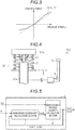
- Fig. 3 is a graph illustrating the damping force fd(y, P) when the damping force control value P is a predetermined value.
- the damping force fd(y, P) is nonlinear with respect to the relative speed y.
- the broken line illustrated in Fig. 3 is a first order approximation formula or an expression based on the first order approximation formula of the damping force fd(y, P) when the damping force control value P is at a predetermined value.
- the first order approximation formula or the expression based on the first order approximation formula corresponds to the linear component described above.
- the state equation can be derived as follows by using equation (1), equation (2), a state variable x1 meaning the relative speed y, a state variable x2 meaning the spring expansion and contraction distance.
- X ′ AX + Gw + Bfn y P
- X' is the derivative of X.
- Y indicates a column vector of (y1, y2)
- y1 relative speed y
- y2 vehicle body acceleration Za.
- C, U, D, and F are row vectors having predetermined values, respectively.
- (C, U) is a column vector with C and U as elements
- (D, F) is a column vector with D and F as elements.
- v indicates observation noise.
- the displacement related quantity estimation device 3 can be configured based on the observer of these equations.
- the model of the damper 20 (see Fig. 2 ) is a simplified version of the damper 20 attached to the vehicle body 100.
- the suspension 300 has a buffer member 23 which protects the damper 20.
- the buffer member 23 limits the operation of the damper 20. Therefore, the operation of the damper 20 can be changed based on not only the configuration of the damper 20 but also the buffer member 23.
- the configuration of the buffer member 23 is omitted. Therefore, if the vibration damping device 22 of the damper 20 is controlled based on the damping force control value P derived by the model, the actual damping effect may diverge from the theoretical damping effect.
- an example of the suspension 300 will be described, and the configuration of the displacement related quantity estimation device 3 reflecting the action of the buffer member 23 will be described.
- the suspension 300 includes the damper 20 and the buffer member 23.
- the buffer member 23 alleviates collision between the support portion 100a (for example, strut mount, component attached to the periphery of strut mount and the like) of the vehicle body 100 to which the damper 20 is attached and the cylinder 22a of the damper 20.
- the buffer member 23 is disposed between the support portion 100a of the vehicle body 100 and the cylinder 22a of the damper 20 and prevents the cylinder 22a of the damper 20 from being in contact with the support portion 100a.
- the buffer member 23 is configured by an expandable and contractible elastic body.
- an end surface of the cylinder 22a is in contact with the buffer member 23.
- the buffer member 23 is compressed by the pressing force of the cylinder 22a and the cylinder 22a receives a force in a direction opposite to the traveling direction from the buffer member 23.
- the buffer member 23 acts as follows.
- the buffer member 23 Since the buffer member 23 is an elastic body, the buffer member 23 affects a term (K ⁇ xs) of the spring in the motion equation of the vehicle body 100 of the above equation (1).
- K ⁇ xs is linear with respect to the spring expansion and contraction distance xs.
- the term "K ⁇ xs” becomes nonlinear, for example, a nonlinear function f(xs) of the variable "xs".
- an observer for estimating y (relative speed) and r (relative displacement) can be obtained from a new state equation and the output equation (4).
- the presence of the buffer member 23 is reflected in y (relative speed) and r (relative displacement) as described above.
- Fig. 5 is a block diagram of the displacement related quantity estimation device 3.
- the displacement related quantity estimation device 3 includes a nonlinear component calculation section 5 and a displacement related quantity calculation section 6.
- the nonlinear component calculation section 5 derives the nonlinear component fnob based on the estimated relative displacement yob2 and the damping force control value P.
- the nonlinear component calculation section 5 has a function (hereinafter referred to as "nonlinear component function") for forming the nonlinear component fnob.
- the nonlinear component function includes the following predetermined function.
- the function derives the nonlinear component fnob based on the estimated relative displacement yob2 and the damping force control value P.
- the nonlinear component fnob indicates a divergence component from the linearity of the damping force with respect to the relative displacement r and is defined as an estimated value of the divergence component. For example, a component obtained by subtracting a linear component approximated to a curve of the damping force plotted with respect to the relative displacement r from the curve is taken as a nonlinear component.
- the function is configured as a map or the like indicating the relationship between variables configured by a pair of the estimated relative displacement yob2 and the damping force control value P and the nonlinear component.
- the nonlinear component fnob indicates the degree of influence thereof when the nonlinear component of the actions of the spring 21 and the buffer member 23 influences the state variables.
- the action of the buffer member 23 contributes to the nonlinear component fnob in particular.
- the function is set based on tests performed in advance.
- the nonlinear component function may include another function (hereinafter, additional function).
- the additional function derives the nonlinear component fnob based on the estimated relative speed yob1 and the damping force control value P.
- the nonlinear component fnob is a nonlinear component which is a divergence component from the linearity of the damping force with respect to the relative speed and is defined as an estimated value of the nonlinear component. For example, a component obtained by subtracting a linear component approximated to a curve of the damping force plotted with respect to the relative speed from the curve is taken as a nonlinear component.
- the additional function is configured as a map or the like indicating a relationship between variables configured by a pair of the estimated relative speed yob1 and the damping force control value P and the nonlinear component.
- the nonlinear component fnob of the actions of the damper 20 affects the state variables
- the nonlinear component fnob indicates the degree of the influence thereof.
- the nonlinear component function includes the functions and an additional function
- the sum of the nonlinear component fnob derived by the first function and the nonlinear component fnob derived by the additional function is added and the sum is output as the nonlinear component fnob.
- the displacement related quantity calculation section 6 derives the estimated relative speed yob1 and the estimated relative displacement yob2 based on the nonlinear component fnob and the state variables of the vehicle body 100.
- the displacement related quantity calculation section 6 is configured based on an observer.
- the vehicle body acceleration Za provided from the vehicle body 100 is used as a state variable.
- the damping force control apparatus 1 of a comparative reference example uses the vehicle body acceleration Za provided from the vehicle body 100 to derive the estimated relative speed yob1 and the damping force control value P.
- the vehicle body acceleration Za indicates the state of the vehicle body 100 at the time when the vehicle body acceleration Za is provided from the vehicle body 100 regardless of the presence or absence of the buffer member 23. Therefore, the vehicle body acceleration Za includes the influence of the contact between the buffer member 23 and the cylinder 22a of the damper 20.
- this point will be described below.
- the acceleration greatly changes.
- the vehicle body acceleration Za used for the calculation at the contact time point is a value obtained immediately before the contact therebetween, the estimated relative speed yob1 estimated at the time point largely diverges from the actual value.
- the damping force control value P derived from the estimated relative speed yob1 deviates from a value suitable for suppressing the vibration of the vehicle body 100.
- the same actions also occur at the time point (hereinafter referred to as separation time point) when the cylinder 22a separates from the buffer member 23 as that in a state where the buffer member 23 and the cylinder 22a are in contact with each other.
- separation time point the time point when the cylinder 22a separates from the buffer member 23 (the point of separation) since the pressing force to the cylinder 22a based on the expansion of the buffer member 23 disappears.
- the acceleration greatly changes.
- the vehicle body acceleration Za used for the calculation at this separation time point is a value obtained immediately before the separation
- the estimated relative speed yob1 estimated at the time point greatly diverges from the actual value.
- the damping force control value P derived from the estimated relative speed yob1 deviates from a value suitable for suppressing the vibration of the vehicle body 100.
- the nonlinear component calculation section 5 estimates the nonlinear component fnob on the nonlinear component fnob used by the displacement related quantity calculation section 6 in calculating the estimated relative speed yob1 based on predetermined information. Specifically, the nonlinear component function of the displacement related quantity calculation section 6 derives the nonlinear component fnob with respect to the estimated relative displacement yob2. The nonlinear component fnob is derived by the above function.
- the nonlinear component fnob may be derived in the range of the estimated relative displacement yob2 in which the buffer member 23 and the cylinder 22a can be in contact with each other. Then, the nonlinear component fnob is used for deriving the estimated relative speed yob1. Accordingly, "divergence" between the estimated relative speed yob1 and the actual relative speed is suppressed. Therefore, according to the nonlinear component fnob including the nonlinear component caused by the estimated relative displacement yob2, the estimated relative speed yob1 is precisely estimated.
- the damping force control apparatus 1 can be configured so that the vehicle body acceleration Za and the vehicle body speed Zb are used as the state variables of the vehicle body 100 as follows.
- the damping force control apparatus 1 is configured to include the vehicle body speed calculation device 4 described above.
- the damping force control apparatus 1 only the vehicle body acceleration Za is input as the state variable of the vehicle body 100.
- the additional function includes a function as a "delay correction term” (hereinafter, “delay correction function”).
- the additional function is a function for improving the following event.
- the estimation accuracy of the estimated relative speed yob1 may decrease.
- the estimated relative speed yob1 and the actual relative speed can greatly diverge. This divergence appears as a delay of the damping force control value P in time series.
- Delay correction function is a calculation term (delay correction term) for suppressing such divergence.
- the delay correction function is, for example, a function with the damping force control value P at the time of calculation as a variable.
- the delay correction function is set in advance as a calculation expression, a map, or the like according to the specification of the damper 20 (full software, full hardware, intermediate state thereof or the like). Therefore, by inputting the damping force control value P derived by calculation to the delay correction function, the nonlinear component is derived from the delay correction function.
- the delay correction function can be configured as a plurality of function groups corresponding to the specification of the damper 20.
- the plurality of function groups is a group of functions set for each different specification of the damper 20 (full software, full hardware, intermediate state thereof or the like).
- the vibration period of the vehicle body is obtained based on actual relative speed data and the specification of the damper 20 can be estimated based on the obtained vibration period. Accordingly, from the estimated specification of the damper 20, a function corresponding to the specification thereof is selected from a group of functions. Then, a nonlinear component is derived by using the selected function.
- the "nonlinear component” derived from the delay correction function (that is, delay correction term) and the “nonlinear component” described in the embodiment are weighted with coefficients, added, and then the result thereof is output.
- the nonlinear component calculation section 5 derives a "nonlinear component" related to the estimated relative displacement yob2 and estimated relative speed yob1 based on the damping force control value P determined by the damping force control value calculation device 2 and the estimated relative displacement yob2 and estimated relative speed yob1 estimated by displacement related quantity estimation device 3.
Landscapes
- Engineering & Computer Science (AREA)
- Mechanical Engineering (AREA)
- Vehicle Body Suspensions (AREA)
Abstract
Description
- This disclosure relates to a damping force control apparatus for a suspension.
- As a damping force control apparatus of a suspension, for example, the technique described in
JP 10-913A - The damping force control apparatus according to the technique includes opening determination means for determining an orifice opening degree of a damper so as to control a damping force. The opening determination means determines the orifice opening degree (damping force control value) based on a vehicle body speed (absolute speed described in Reference 1) and a relative speed of a vehicle wheel with respect to a vehicle body. Here, each of the vehicle body speed and the relative speed is calculated based on the output (acceleration) obtained from an acceleration sensor of the vehicle body.
- The relative speed is estimated by applying the Kalman filter theory to a modeled damper. In applying the Kalman filter theory, the damping force of the damper is classified as a linear component and a nonlinear component.
- In addition, in
JP 2010-58541A - However, in the estimation of the relative speed according to the related art described above, the estimated relative speed is greatly diverged from the actual relative speed and as a result, the orifice opening degree (damping force control value) may not be calculated as an appropriate value, that is, a value suitable for suppressing vibration of the vehicle body.
-
- (1) A damping force control apparatus for a suspension according to an aspect of this disclosure is applied to a damper whose damping force is capable of being set based on a damping force control value and controls the damping force control value, the damper being attached to a support portion with a buffer member interposed between the support portion of a vehicle body and a cylinder of the damper, the apparatus including: a displacement related quantity estimation device which estimates relative displacement of a vehicle wheel with respect to the vehicle body and a relative speed of the vehicle wheel with respect to the vehicle body as estimated relative displacement and an estimated relative speed, and a damping force control value calculation device which determines the damping force control value so as to suppress vibration of the vehicle body based on state variables provided from the vehicle body and the estimated relative speed which is estimated by the displacement related quantity estimation device, in which the displacement related quantity estimation device estimates the estimated relative speed and the estimated relative displacement based on the state variables, the damping force control value which is determined by the damping force control calculation device, and the estimated relative speed and the estimated relative displacement which are estimated by the displacement related quantity estimation device itself.
With this configuration, the estimated relative speed and the estimated relative displacement output by the displacement related quantity estimation device are fed back to the displacement related quantity estimation device. Therefore, since the estimated relative displacement is reflected in the estimated relative speed and the estimated relative displacement during the calculation of the estimated relative speed and the estimated relative displacement, accuracy of the estimated relative speed and the estimated relative displacement is improved and as a result, accuracy of the damping force control value is improved compared to the reference damping force control apparatus that does not reflect the estimated relative displacement. - (2) In the damping force control apparatus for a suspension, the displacement related quantity estimation device may include a nonlinear component calculation section which derives a nonlinear component with respect to the estimated relative displacement based on the damping force control value determined by the damping force control value calculation device and the estimated relative displacement estimated by the displacement related quantity estimation device, and a displacement related quantity calculation section which estimates the estimated relative speed and the estimated relative displacement based on the nonlinear component and the state variables.
With this configuration, the displacement related quantity estimation device derives the nonlinear component. The nonlinear component is derived based on the damping force control value and the estimated relative displacement. Therefore, since the estimated relative displacement is reflected in the nonlinear component, the accuracy of the estimated relative speed and the estimated relative displacement is improved as compared with a case where the nonlinear component is derived without using the estimated relative displacement. - (3) In the damping force control apparatus for a suspension, the nonlinear component calculation section may have a function of deriving the nonlinear component in the range of the estimated relative displacement in which the buffer member and the cylinder of the damper can be in contact with each other. With this configuration, at least the nonlinear component is derived within the range of the estimated relative displacement in which the buffer member and the cylinder of the damper can be in contact with each other.
- (4) In the damping force control apparatus for a suspension, when the estimated relative displacement is within a specified range, the function may derive the nonlinear component based on all the variables of a variable group consisting of the damping force control value, the estimated relative speed, and the estimated relative displacement, and when the estimated relative displacement is outside the specified range, the function may correct the estimated relative displacement by using variables other than the estimated relative displacement of the variable group, and the specified range corresponds to a distance range between the vehicle body and the vehicle wheel in which the buffer member and the damper are in contact with each other.
With this configuration, only when the estimated relative displacement is within the specified range, the nonlinear component is derived based on the variables including the estimated relative displacement (that is, estimated relative displacement, estimated relative speed, and damping force control value). On the other hand, when the estimated relative displacement is outside the specified range, a nonlinear component is derived based on the variables other than the estimated relative displacement (that is, estimated relative speed and damping force control value). Therefore, the burden on the damping force control apparatus is reduced as compared with a case where the nonlinear component is always derived using all variables. - (5) A suspension according to an aspect of this disclosure includes: any of the damping force control apparatuses described above; a damper which is controlled by the damping force control apparatus; and a buffer member which alleviates a collision between the vehicle body to which the damper is attached and the damper.
- With this configuration, the damper is controlled by the damping force control value reflecting the estimated relative displacement. Therefore, the damping characteristic of the suspension is improved.
- The damping force control apparatus for a suspension derives a damping force control value suitable for vibration suppression of the vehicle body.
- The foregoing and additional features and characteristics of this disclosure will become more apparent from the following detailed description considered with the reference to the accompanying drawings, wherein:
-
Fig. 1 is a block diagram of a damping force control apparatus for a suspension; -
Fig. 2 is a schematic diagram of a damper; -
Fig. 3 is a graph of a damping force characteristic illustrating a change in a damping force with respect to a relative speed; -
Fig. 4 is a schematic diagram of a suspension; and -
Fig. 5 is a block diagram of a displacement related quantity estimation device. - With reference to
Figs. 1 to 5 , a damping force control apparatus for a suspension will be described. - The damping force control apparatus for a suspension (hereinafter, simply referred to as "damping
force control apparatus 1") controls a damping force of a semi-active damper which is a constituent element of a suspension. The semi-active damper variably sets the damping force based on a damping force control value P input from the outside. The damping force indicates a resistance force which hinders the movement of the piston. In the following description, the semi-active damper is simply referred to as "damper 20". - The damping
force control apparatus 1 calculates the damping force control value P based on a motion state of avehicle body 100 and outputs the damping force control value P to thedamper 20. Thedamper 20 sets the damping force based on the damping force control value P. For example, thedamper 20 changes an opening degree of an orifice provided on a piston of thedamper 20 based on the damping force control value P and changes an opening degree between a valve body and a valve seat. Accordingly, thedamper 20 adjusts the damping force of thedamper 20 by controlling a distribution amount of lubricating oil distributed between two oil chambers partitioned by the piston in thedamper 20. - As illustrated in
Fig. 1 , the dampingforce control apparatus 1 calculates the damping force control value P which is output to thedamper 20 based on an acceleration (hereinafter, referred to as "vehicle body acceleration Za") of the vehicle body 100 (seeFIG. 2 ) in the vertical direction (direction alongdamper 20 shaft, the same as below) and a speed (hereinafter, referred to as "vehicle speed Zb") of thevehicle body 100 in the vertical direction. - The vehicle body speed Zb is derived by a vehicle body
speed calculation device 4. - The vehicle body
speed calculation device 4 derives the vehicle body speed Zb by integrating the vehicle body acceleration Za. In the vehicle body acceleration Za, a signal outputted from anacceleration sensor 10 mounted on thevehicle body 100 and detecting the acceleration (vehicle body acceleration Za) of thevehicle body 100 in the vertical direction is used. - The damping
force control apparatus 1 includes a damping force controlvalue calculation device 2 and a displacement relatedquantity estimation device 3. - The damping force control
value calculation device 2 calculates the damping force control value P based on state variables and an estimated relative speed yob1. The state variables are variables such as the vehicle body acceleration Za and the vehicle body speed Zb. For example, the vehicle body speed Zb is used as a state variable in the damping force controlvalue calculation device 2. The damping force controlvalue calculation device 2 is constructed based on the skyhook control theory or the H∞ control theory. The estimated relative speed yob1 indicates an estimated value of the speed (hereinafter referred to as "relative speed y") of thevehicle wheel 200 with respect to thevehicle body 100. - The estimated relative speed yob1 is derived by the displacement related
quantity estimation device 3. - The estimated relative speed yob1 is derived based on the state variables and the damping force control value P output from the damping force control
value calculation device 2. In the displacement relatedquantity estimation device 3, for example, the vehicle body acceleration Za is used as a state variable. The displacement relatedquantity estimation device 3 is configured based on the Kalman filter theory. The displacement relatedquantity estimation device 3 derives the estimated relative displacement yob2 in addition to the estimated relative speed yob1 as to be described below. The estimated relative displacement yob2 indicates an estimated value of the displacement (hereinafter, referred to as "relative displacement r") of thevehicle wheel 200 with respect to thevehicle body 100. - With reference to
Figs. 1 to 5 , a configuration example of the displacement relatedquantity estimation device 3 will be described. -
Fig. 2 is a model of thedamper 20 which is assumed based on the Kalman filter theory. Thedamper 20 connects between thevehicle body 100 and thevehicle wheel 200. In other words, thevehicle body 100 is supported by thevehicle wheel 200 and thedamper 20. - As illustrated in
Fig. 2 , thedamper 20 is configured by aspring 21 and a vibration damping device 22 (shock absorber). - When mass of the
vehicle body 100 is referred to as "M", the vehicle body acceleration Za is referred to as "Za", a spring coefficient is referred to as K, a spring expansion and contraction distance is referred to as xs, the damping force of thevibration damping device 22 is referred to as fd(y, P), the damping force control value P of thevibration damping device 22 in thedamper 20 is referred to as "P", and the relative speed y is referred to as "y", a motion equation of thevehicle body 100 is as follows.
- "K·xs" indicates an elastic force of the
spring 21. The damping force "fd(y, P)" of thevibration damping device 22 is generally nonlinear with respect to the relative speed y (seeFig. 3 ). The damping force characteristic indicating the change in the damping force with respect to the relative speed y changes according to the damping force control value P. In view of the above, in the embodiment, the damping force fd(y, P) of thevibration damping device 22 is classified as a linear component and a nonlinear component. -
Fig. 3 is a graph illustrating the damping force fd(y, P) when the damping force control value P is a predetermined value. - As described above, the damping force fd(y, P) is nonlinear with respect to the relative speed y. The broken line illustrated in
Fig. 3 is a first order approximation formula or an expression based on the first order approximation formula of the damping force fd(y, P) when the damping force control value P is at a predetermined value. The first order approximation formula or the expression based on the first order approximation formula corresponds to the linear component described above. - When the coefficient of the linear component is set to as Co and the nonlinear component is set to as a function fn(y, P) of the relative speed y and the damping force control value P, the damping force fd(y, P) is expressed as follows.

- The state equation can be derived as follows by using equation (1), equation (2), a state variable x1 meaning the relative speed y, a state variable x2 meaning the spring expansion and contraction distance.

- Here, a column vector of X=(x1, x2), A, G, B indicates a matrix having predetermined values. X' is the derivative of X.
- On the other hand, the following output equation is obtained from a relationship between the relative speed y and the vehicle body acceleration Za.

- Here, Y indicates a column vector of (y1, y2), y1=relative speed y, and y2=vehicle body acceleration Za. C, U, D, and F are row vectors having predetermined values, respectively. (C, U) is a column vector with C and U as elements, and (D, F) is a column vector with D and F as elements. v indicates observation noise.
- Using the Kalman filter theory, an observer for estimating y (relative speed) and r (relative displacement) based on the equations (3) and (4) described above can be obtained. In other words, the displacement related
quantity estimation device 3 can be configured based on the observer of these equations. - Meanwhile, the model of the damper 20 (see
Fig. 2 ) is a simplified version of thedamper 20 attached to thevehicle body 100. On the other hand, thesuspension 300 has abuffer member 23 which protects thedamper 20. Thebuffer member 23 limits the operation of thedamper 20. Therefore, the operation of thedamper 20 can be changed based on not only the configuration of thedamper 20 but also thebuffer member 23. In the above model, the configuration of thebuffer member 23 is omitted. Therefore, if thevibration damping device 22 of thedamper 20 is controlled based on the damping force control value P derived by the model, the actual damping effect may diverge from the theoretical damping effect. Hereinafter, an example of thesuspension 300 will be described, and the configuration of the displacement relatedquantity estimation device 3 reflecting the action of thebuffer member 23 will be described. - An example of the
suspension 300 will be described with reference toFig. 4 . - The
suspension 300 includes thedamper 20 and thebuffer member 23. Thebuffer member 23 alleviates collision between the support portion 100a (for example, strut mount, component attached to the periphery of strut mount and the like) of thevehicle body 100 to which thedamper 20 is attached and thecylinder 22a of thedamper 20. - Specifically, the
buffer member 23 is disposed between the support portion 100a of thevehicle body 100 and thecylinder 22a of thedamper 20 and prevents thecylinder 22a of thedamper 20 from being in contact with the support portion 100a. Thebuffer member 23 is configured by an expandable and contractible elastic body. When thevibration damping device 22 operates and thus the distance between thecylinder 22a and the support portion 100a falls within a specified range, an end surface of thecylinder 22a is in contact with thebuffer member 23. When thecylinder 22a further approaches the support portion 100a, thebuffer member 23 is compressed by the pressing force of thecylinder 22a and thecylinder 22a receives a force in a direction opposite to the traveling direction from thebuffer member 23. As a result, thebuffer member 23 acts as follows. In other words, when a force to push up thevehicle wheel 200 is applied to thedamper 20, thecylinder 22a abruptly moves due to the force, but thebuffer member 23 prevents thecylinder 22a from being directly in contact with the support portion 100a and alleviates the moving speed of thecylinder 22a. - Since the
buffer member 23 is an elastic body, thebuffer member 23 affects a term (K·xs) of the spring in the motion equation of thevehicle body 100 of the above equation (1). The term "K·xs" is linear with respect to the spring expansion and contraction distance xs. However, due to the presence of thebuffer member 23, in practice, the term "K·xs" becomes nonlinear, for example, a nonlinear function f(xs) of the variable "xs". When the equation "M·Za=f(xs)+fd(y, P)···(1)"' set described above and the above equation (2) are used, a new state equation can be obtained. Based on the Kalman filter theory, an observer for estimating y (relative speed) and r (relative displacement) can be obtained from a new state equation and the output equation (4). The presence of thebuffer member 23 is reflected in y (relative speed) and r (relative displacement) as described above. -
Fig. 5 is a block diagram of the displacement relatedquantity estimation device 3. The displacement relatedquantity estimation device 3 includes a nonlinearcomponent calculation section 5 and a displacement relatedquantity calculation section 6. - The nonlinear
component calculation section 5 derives the nonlinear component fnob based on the estimated relative displacement yob2 and the damping force control value P. - The nonlinear
component calculation section 5 has a function (hereinafter referred to as "nonlinear component function") for forming the nonlinear component fnob. - The nonlinear component function includes the following predetermined function. The function derives the nonlinear component fnob based on the estimated relative displacement yob2 and the damping force control value P. The nonlinear component fnob indicates a divergence component from the linearity of the damping force with respect to the relative displacement r and is defined as an estimated value of the divergence component. For example, a component obtained by subtracting a linear component approximated to a curve of the damping force plotted with respect to the relative displacement r from the curve is taken as a nonlinear component. The function is configured as a map or the like indicating the relationship between variables configured by a pair of the estimated relative displacement yob2 and the damping force control value P and the nonlinear component.
- The nonlinear component fnob indicates the degree of influence thereof when the nonlinear component of the actions of the
spring 21 and thebuffer member 23 influences the state variables. The action of thebuffer member 23 contributes to the nonlinear component fnob in particular. The function is set based on tests performed in advance. - In addition to the functions described above, the nonlinear component function may include another function (hereinafter, additional function). The additional function derives the nonlinear component fnob based on the estimated relative speed yob1 and the damping force control value P. The nonlinear component fnob is a nonlinear component which is a divergence component from the linearity of the damping force with respect to the relative speed and is defined as an estimated value of the nonlinear component. For example, a component obtained by subtracting a linear component approximated to a curve of the damping force plotted with respect to the relative speed from the curve is taken as a nonlinear component. The additional function is configured as a map or the like indicating a relationship between variables configured by a pair of the estimated relative speed yob1 and the damping force control value P and the nonlinear component.
- When the nonlinear component fnob of the actions of the
damper 20 affects the state variables, the nonlinear component fnob indicates the degree of the influence thereof. In a case where the nonlinear component function includes the functions and an additional function, the sum of the nonlinear component fnob derived by the first function and the nonlinear component fnob derived by the additional function is added and the sum is output as the nonlinear component fnob. - The displacement related
quantity calculation section 6 derives the estimated relative speed yob1 and the estimated relative displacement yob2 based on the nonlinear component fnob and the state variables of thevehicle body 100. The displacement relatedquantity calculation section 6 is configured based on an observer. In the embodiment, the vehicle body acceleration Za provided from thevehicle body 100 is used as a state variable. - Next, the action of the damping
force control apparatus 1 will be described. - First, the damping
force control apparatus 1 of a comparative reference example will be described. Using the observer constructed from the model of the damper 20 (seeFig. 2 ), the dampingforce control apparatus 1 of the reference example uses the vehicle body acceleration Za provided from thevehicle body 100 to derive the estimated relative speed yob1 and the damping force control value P. The vehicle body acceleration Za indicates the state of thevehicle body 100 at the time when the vehicle body acceleration Za is provided from thevehicle body 100 regardless of the presence or absence of thebuffer member 23. Therefore, the vehicle body acceleration Za includes the influence of the contact between thebuffer member 23 and thecylinder 22a of thedamper 20. However, it is difficult to accurately estimate the estimated relative speed yob1 in the calculation of the estimated relative speed yob1 in the reference example. Hereinafter, this point will be described below. - At the time point when the
cylinder 22a is in contact with the buffer member 23 (hereinafter referred to as contact time point) since the movement of thecylinder 22a is hindered, the acceleration greatly changes. On the other hand, since the vehicle body acceleration Za used for the calculation at the contact time point is a value obtained immediately before the contact therebetween, the estimated relative speed yob1 estimated at the time point largely diverges from the actual value. As a result, the damping force control value P derived from the estimated relative speed yob1 deviates from a value suitable for suppressing the vibration of thevehicle body 100. - In addition, the same actions also occur at the time point (hereinafter referred to as separation time point) when the
cylinder 22a separates from thebuffer member 23 as that in a state where thebuffer member 23 and thecylinder 22a are in contact with each other. In other words, at the time point when thecylinder 22a separates from the buffer member 23 (the point of separation) since the pressing force to thecylinder 22a based on the expansion of thebuffer member 23 disappears, the acceleration greatly changes. On the other hand, since the vehicle body acceleration Za used for the calculation at this separation time point is a value obtained immediately before the separation, the estimated relative speed yob1 estimated at the time point greatly diverges from the actual value. As a result, the damping force control value P derived from the estimated relative speed yob1 deviates from a value suitable for suppressing the vibration of thevehicle body 100. - In addition, such "divergence" of the vehicle body acceleration Za occurs similarly even at time points other than the contact time point and the separation time point. In other words, it is considered that the divergence of the estimated relative speed yob1 occurs for the same reason only in a period in which the
buffer member 23 and thecylinder 22a act a force on each other by being in contact with each other. - Therefore, in the embodiment, in the calculation for deriving the estimated relative speed yob1, information on the estimated relative displacement yob2 is reflected. The nonlinear
component calculation section 5 estimates the nonlinear component fnob on the nonlinear component fnob used by the displacement relatedquantity calculation section 6 in calculating the estimated relative speed yob1 based on predetermined information. Specifically, the nonlinear component function of the displacement relatedquantity calculation section 6 derives the nonlinear component fnob with respect to the estimated relative displacement yob2. The nonlinear component fnob is derived by the above function. The nonlinear component fnob may be derived in the range of the estimated relative displacement yob2 in which thebuffer member 23 and thecylinder 22a can be in contact with each other. Then, the nonlinear component fnob is used for deriving the estimated relative speed yob1. Accordingly, "divergence" between the estimated relative speed yob1 and the actual relative speed is suppressed. Therefore, according to the nonlinear component fnob including the nonlinear component caused by the estimated relative displacement yob2, the estimated relative speed yob1 is precisely estimated. - Next, effects of the damping
force control apparatus 1 according to the present embodiment will be described. - (1) The damping
force control apparatus 1 includes the damping force controlvalue calculation device 2 and the displacement relatedquantity estimation device 3. The damping force controlvalue calculation device 2 determines the damping force control value P based on the state variables of thevehicle body 100 and the estimated relative speed yob1 (seeFig. 1 ). The displacement relatedquantity estimation device 3 estimates the estimated relative speed yob1 and the estimated relative displacement yob2 based on the estimated relative speed yob1 and the estimated relative displacement yob2 estimated by the state variables of thevehicle body 100, the damping force control value P, and the displacement relatedquantity estimation device 3 itself (seeFig. 5 ).
With the configuration, the estimated relative speed yob1 and the estimated relative displacement yob2 output by the displacement relatedquantity estimation device 3 are fed back to the displacement relatedquantity estimation device 3. Therefore, since the estimated relative displacement yob2 is reflected in the estimated relative speed yob1 and the estimated relative displacement yob2 during the calculation of the estimated relative speed yob1 and the estimated relative displacement yob2, accuracy of the estimated relative speed yob1 and the estimated relative displacement yob2 is improved and as a result, accuracy of the damping force control value P is improved compared to the reference damping force control apparatus that does not reflect the estimated relative displacement yob2. - (2) The displacement related
quantity estimation device 3 includes the nonlinearcomponent calculation section 5 and the displacement relatedquantity calculation section 6. The nonlinearcomponent calculation section 5 derives the nonlinear component fnob based on the damping force control value P and the estimated relative displacement yob2. The displacement relatedquantity calculation section 6 estimates the estimated relative speed yob1 and the estimated relative displacement yob2 based on the nonlinear component fnob and the state variables.
With the configuration, the displacement relatedquantity estimation device 3 derives the nonlinear component fnob. The nonlinear component fnob is derived based on the damping force control value P and the estimated relative displacement yob2. Therefore, since the estimated relative displacement yob2 is reflected in the nonlinear component fnob, the accuracy of the estimated relative speed yob1 and the estimated relative displacement yob2 is improved compared to a case where the nonlinear component fnob is derived without using the estimated relative displacement yob2. - (3) In the damping
force control apparatus 1, the nonlinearcomponent calculation section 5 has a function of deriving the nonlinear component fnob in the range of the estimated relative displacement that the buffer member and the cylinder of the damper can be in contact with each other. With the configuration, at least the nonlinear component fnob is derived within the range of the estimated relative displacement in which thebuffer member 23 and thecylinder 22a of thedamper 20 can be in contact with each other. - (4) The use range of the estimated relative speed yob1, the estimated relative displacement yob2, and the damping force control value P is limited in a predetermined function (nonlinear component function described above). For example, the predetermined function (nonlinear component function described above) derives the nonlinear component fnob by using the variables (that is, estimated relative displacement yob2, estimated relative speed yob1, and damping force control value P) including the estimated relative displacement yob2 only when the estimated relative displacement yob2 is within the specified range. On the other hand, when the estimated relative displacement yob2 is outside the specified range, the nonlinear component fnob is derived by using variables (that is, estimated relative speed yob1 and damping force control value P) other than the estimated relative displacement yob2. Here, within the specified range, a distance range between the
vehicle body 100 and thevehicle wheel 200 which constitutes a state where thedamper 20 is in contact with thebuffer member 23 is indicated. With such a configuration, the burden on the dampingforce control apparatus 1 is reduced as compared with a case where the nonlinear component fnob is always derived by using all variables. - (5) The suspension 300 (see
Fig. 4 ) includes the dampingforce control apparatus 1, thedamper 20 which is controlled by the dampingforce control apparatus 1, and thebuffer member 23 which alleviates collision between thevehicle body 100 to which thedamper 20 is attached and thecylinder 22a of thedamper 20. With the configuration, thedamper 20 is controlled by the damping force control value P on which the estimated relative displacement yob2 is reflected. Therefore, the damping characteristic of thesuspension 300 is improved. - In the damping
force control apparatus 1 of the embodiment, the dampingforce control apparatus 1 can be configured so that the vehicle body acceleration Za and the vehicle body speed Zb are used as the state variables of thevehicle body 100 as follows. In other words, the dampingforce control apparatus 1 is configured to include the vehicle bodyspeed calculation device 4 described above. In this case, in the dampingforce control apparatus 1, only the vehicle body acceleration Za is input as the state variable of thevehicle body 100. - An example of "additional function" described in the embodiment described above will be described.
- The additional function includes a function as a "delay correction term" (hereinafter, "delay correction function"). The additional function is a function for improving the following event.
- When the specification of the actual suspension is largely diverged from that of the model of the
damper 20, the estimation accuracy of the estimated relative speed yob1 may decrease. For example, in a case where the specification of the actual suspension is full hardware or full software, the estimated relative speed yob1 and the actual relative speed can greatly diverge. This divergence appears as a delay of the damping force control value P in time series. - "Delay correction function" is a calculation term (delay correction term) for suppressing such divergence.
- The delay correction function is, for example, a function with the damping force control value P at the time of calculation as a variable. The delay correction function is set in advance as a calculation expression, a map, or the like according to the specification of the damper 20 (full software, full hardware, intermediate state thereof or the like). Therefore, by inputting the damping force control value P derived by calculation to the delay correction function, the nonlinear component is derived from the delay correction function.
- In addition, the delay correction function can be configured as a plurality of function groups corresponding to the specification of the
damper 20. The plurality of function groups is a group of functions set for each different specification of the damper 20 (full software, full hardware, intermediate state thereof or the like). The vibration period of the vehicle body is obtained based on actual relative speed data and the specification of thedamper 20 can be estimated based on the obtained vibration period. Accordingly, from the estimated specification of thedamper 20, a function corresponding to the specification thereof is selected from a group of functions. Then, a nonlinear component is derived by using the selected function. - In the nonlinear
component calculation section 5, the "nonlinear component" derived from the delay correction function (that is, delay correction term) and the "nonlinear component" described in the embodiment are weighted with coefficients, added, and then the result thereof is output. - In the case of this example, the nonlinear
component calculation section 5 derives a "nonlinear component" related to the estimated relative displacement yob2 and estimated relative speed yob1 based on the damping force control value P determined by the damping force controlvalue calculation device 2 and the estimated relative displacement yob2 and estimated relative speed yob1 estimated by displacement relatedquantity estimation device 3. - The principles, preferred embodiment and mode of operation of the present invention have been described in the foregoing specification. However, the invention which is intended to be protected is not to be construed as limited to the particular embodiments disclosed. Further, the embodiments described herein are to be regarded as illustrative rather than restrictive. Variations and changes may be made by others, and equivalents employed, without departing from the spirit of the present invention. Accordingly, it is expressly intended that all such variations, changes and equivalents which fall within the spirit and scope of the present invention as defined in the claims, be embraced thereby.
Claims (5)
- A damping force control apparatus (1) for a suspension that is applied to a damper (20) whose damping force is capable of being set based on a damping force control value (P) and that controls the damping force control value, the damper being attached to a support portion (100a) with a buffer member (23) interposed between the support portion of a vehicle body (100) and a cylinder (22a) of the damper, the apparatus comprising:a displacement related quantity estimation device (3) which estimates relative displacement (r) of a vehicle wheel (200) with respect to the vehicle body and a relative speed (y) of the vehicle wheel with respect to the vehicle body as estimated relative displacement (yob2) and an estimated relative speed (yob1); anda damping force control value calculation device (2) which determines the damping force control value so as to suppress vibration of the vehicle body based on state variables provided from the vehicle body and the estimated relative speed which is estimated by the displacement related quantity estimation device,wherein the displacement related quantity estimation device estimates the estimated relative speed and the estimated relative displacement based on the state variables, the damping force control value which is determined by the damping force control calculation device, and the estimated relative speed and the estimated relative displacement which are estimated by the displacement related quantity estimation device itself.
- The damping force control apparatus for a suspension according to claim 1,
wherein the displacement related quantity estimation device includes
a nonlinear component calculation section (5) which derives a nonlinear component (fnob) with respect to the estimated relative displacement based on the damping force control value determined by the damping force control value calculation device and the estimated relative displacement estimated by the displacement related quantity estimation device, and
a displacement related quantity calculation section (6) which estimates the estimated relative speed and the estimated relative displacement based on the nonlinear component and the state variables. - The damping force control apparatus for a suspension according to claim 2,
wherein the nonlinear component calculation section has a function of deriving the nonlinear component in the range of the estimated relative displacement in which the buffer member and the cylinder of the damper can be in contact with each other. - The damping force control apparatus for a suspension according to claim 3,
wherein when the estimated relative displacement is within a specified range, the function derives the nonlinear component based on all the variables of a variable group consisting of the damping force control value, the estimated relative speed, and the estimated relative displacement, and when the estimated relative displacement is outside the specified range, the function corrects the estimated relative displacement by using variables other than the estimated relative displacement of the variable group, and
wherein the specified range corresponds to a distance range between the vehicle body and the vehicle wheel in which the buffer member and the damper are in contact with each other. - A suspension comprising:the damping force control apparatus according to any one of claims 1 to 4;a damper (20) which is controlled by the damping force control apparatus; anda buffer member (23) which alleviates a collision between the vehicle body to which the damper is attached and the damper.
Applications Claiming Priority (1)
| Application Number | Priority Date | Filing Date | Title |
|---|---|---|---|
| JP2016208866A JP6747239B2 (en) | 2016-10-25 | 2016-10-25 | Suspension damping force control device |
Publications (2)
| Publication Number | Publication Date |
|---|---|
| EP3318432A1 true EP3318432A1 (en) | 2018-05-09 |
| EP3318432B1 EP3318432B1 (en) | 2021-07-07 |
Family
ID=60161977
Family Applications (1)
| Application Number | Title | Priority Date | Filing Date |
|---|---|---|---|
| EP17197228.4A Active EP3318432B1 (en) | 2016-10-25 | 2017-10-19 | Damping force control apparatus for suspension |
Country Status (4)
| Country | Link |
|---|---|
| US (1) | US10625558B2 (en) |
| EP (1) | EP3318432B1 (en) |
| JP (1) | JP6747239B2 (en) |
| CN (1) | CN107972439B (en) |
Families Citing this family (6)
| Publication number | Priority date | Publication date | Assignee | Title |
|---|---|---|---|---|
| JP6286091B1 (en) | 2017-05-30 | 2018-02-28 | 株式会社ショーワ | Vehicle state estimation device, control device, suspension control device, and suspension device. |
| JP6286092B1 (en) * | 2017-05-30 | 2018-02-28 | 株式会社ショーワ | Suspension control device and suspension device. |
| JP7028649B2 (en) * | 2018-01-10 | 2022-03-02 | 日立Astemo株式会社 | Vehicle, vehicle motion state estimation device and vehicle motion state estimation method |
| CN111959218B (en) * | 2020-07-24 | 2021-12-07 | 中北大学 | Semi-active suspension ceiling damping control method based on damping force closed-loop control |
| KR102413570B1 (en) * | 2021-11-19 | 2022-06-27 | 한국자동차연구원 | Method of predicting life time of damper for vehicle |
| US20250282194A1 (en) * | 2024-03-05 | 2025-09-11 | Polaris Industries Inc. | Vehicle having adjustable compression and rebound damping |
Citations (8)
| Publication number | Priority date | Publication date | Assignee | Title |
|---|---|---|---|---|
| US5097419A (en) * | 1990-06-08 | 1992-03-17 | Monroe Auto Equipment Company | Method and apparatus for dynamic leveling |
| US5497324A (en) * | 1991-05-20 | 1996-03-05 | General Motors Corporation | Vehicle suspension system with gain scheduling |
| JPH08290713A (en) * | 1995-04-25 | 1996-11-05 | Nissan Motor Co Ltd | Suspension control device |
| JPH10913A (en) | 1996-06-13 | 1998-01-06 | Toyota Motor Corp | Damping force control device for vehicle suspension system |
| JP2001287528A (en) * | 2000-04-10 | 2001-10-16 | Toyota Motor Corp | Vehicle sprung speed estimation device |
| DE102004044474A1 (en) * | 2004-09-15 | 2006-03-30 | Bayerische Motoren Werke Ag | Method for activation of active or semi-active shock absorber in chassis of vehicle, using various parameters |
| JP2010058541A (en) | 2008-09-01 | 2010-03-18 | Hitachi Automotive Systems Ltd | State estimation device, suspension control device, and suspension system |
| US20160176259A1 (en) * | 2014-12-18 | 2016-06-23 | Aisin Seiki Kabushiki Kaisha | Damping force control apparatus of suspension |
Family Cites Families (29)
| Publication number | Priority date | Publication date | Assignee | Title |
|---|---|---|---|---|
| JPS56104910A (en) * | 1980-01-24 | 1981-08-21 | Sumitomo Chem Co Ltd | Production of highly crystalline olefin polymer |
| JPS61163011A (en) * | 1985-01-14 | 1986-07-23 | Nissan Motor Co Ltd | Electronic control shock absorber |
| US5276621A (en) * | 1991-05-20 | 1994-01-04 | General Motors Corporation | Quarter car variable force suspension system control |
| JP2001001736A (en) * | 1999-04-20 | 2001-01-09 | Toyota Motor Corp | Damping force control device |
| EP1623856B1 (en) * | 2004-08-06 | 2012-02-22 | Honda Motor Co., Ltd. | Suspension control system |
| JP2006307797A (en) * | 2005-05-02 | 2006-11-09 | Yamaha Motor Co Ltd | Engine control device and engine control method for saddle riding type vehicle |
| US7520832B2 (en) * | 2005-05-17 | 2009-04-21 | Nsk Ltd. | Continuously variable transmission system |
| FR2890903B1 (en) * | 2005-09-22 | 2008-12-05 | Peugeot Citroen Automobiles Sa | SUSPENSION CONTROL DEVICE, VEHICLE EQUIPPED WITH SAME, METHOD OF OBTAINING AND PROGRAM. |
| FR2890902B1 (en) * | 2005-09-22 | 2007-12-14 | Peugeot Citroen Automobiles Sa | SUSPENSION CONTROL DEVICE, VEHICLE PROVIDED WITH SAME, METHOD OF OBTAINING AND PROGRAM |
| DE102006039353A1 (en) * | 2006-08-22 | 2008-03-06 | Daimler Ag | Device and method for influencing the spring force characteristic of an active chassis of a motor vehicle |
| JP5067620B2 (en) * | 2007-09-28 | 2012-11-07 | 日立オートモティブシステムズ株式会社 | Suspension control device |
| EP2262102A4 (en) * | 2008-04-02 | 2012-03-07 | Nissan Motor | Electrically-powered actuator driving control apparatus and driving control method and vehicle having electrically-powered actuator driving control apparatus |
| JP4920006B2 (en) * | 2008-05-15 | 2012-04-18 | トヨタ自動車株式会社 | Vehicle suspension system |
| JP5212015B2 (en) * | 2008-10-27 | 2013-06-19 | アイシン精機株式会社 | Damping force control device |
| JP5246269B2 (en) * | 2008-12-25 | 2013-07-24 | トヨタ自動車株式会社 | Damping force control device |
| JP5195908B2 (en) * | 2009-03-31 | 2013-05-15 | トヨタ自動車株式会社 | Damping force control device |
| FR2966190B1 (en) * | 2010-10-13 | 2012-12-21 | Somfy Sas | METHOD FOR OPERATING A MANEUVER ACTUATOR OF A ROLL-IN MOBILE ELEMENT OF A DOMOTIC EQUIPMENT AND ACTUATOR OPERATING ACCORDING TO THIS METHOD |
| DE102011006679B4 (en) * | 2011-03-16 | 2018-07-12 | Ferrobotics Compliant Robot Technology Gmbh | Active handling device and method for contact tasks |
| EP2803513B1 (en) * | 2012-01-11 | 2016-05-11 | Toyota Jidosha Kabushiki Kaisha | Vehicle |
| JP5740358B2 (en) * | 2012-06-29 | 2015-06-24 | 本田技研工業株式会社 | Suspension control device |
| JP6026207B2 (en) * | 2012-09-28 | 2016-11-16 | 日立オートモティブシステムズ株式会社 | Suspension control device |
| JP5746246B2 (en) * | 2013-03-13 | 2015-07-08 | カヤバ工業株式会社 | Damper control device |
| DE102014104176A1 (en) * | 2013-03-28 | 2014-10-02 | Fuji Jukogyo Kabushiki Kaisha | suspension device |
| JP6349684B2 (en) * | 2013-11-11 | 2018-07-04 | トヨタ自動車株式会社 | Fuel tank |
| JP5983597B2 (en) * | 2013-12-26 | 2016-08-31 | トヨタ自動車株式会社 | Vehicle state estimation device, vehicle state estimation method, and vehicle control device |
| JP2016020118A (en) * | 2014-07-11 | 2016-02-04 | 株式会社デンソー | Vehicle control device |
| CN104317983B (en) * | 2014-09-03 | 2018-09-18 | 山东理工大学 | The design method of feed energy suspension generator power based on damper speed characteristics |
| CN105840752B (en) * | 2015-01-12 | 2018-04-17 | 上银科技股份有限公司 | Limited travel ball screw |
| US20170268912A1 (en) * | 2016-03-18 | 2017-09-21 | CENTRE DE RECHERCHE INDUSTRIELLE DU QUéBEC | System and method for controlling sensor data generation |
-
2016
- 2016-10-25 JP JP2016208866A patent/JP6747239B2/en active Active
-
2017
- 2017-10-19 EP EP17197228.4A patent/EP3318432B1/en active Active
- 2017-10-23 US US15/790,734 patent/US10625558B2/en active Active
- 2017-10-24 CN CN201711004844.3A patent/CN107972439B/en active Active
Patent Citations (8)
| Publication number | Priority date | Publication date | Assignee | Title |
|---|---|---|---|---|
| US5097419A (en) * | 1990-06-08 | 1992-03-17 | Monroe Auto Equipment Company | Method and apparatus for dynamic leveling |
| US5497324A (en) * | 1991-05-20 | 1996-03-05 | General Motors Corporation | Vehicle suspension system with gain scheduling |
| JPH08290713A (en) * | 1995-04-25 | 1996-11-05 | Nissan Motor Co Ltd | Suspension control device |
| JPH10913A (en) | 1996-06-13 | 1998-01-06 | Toyota Motor Corp | Damping force control device for vehicle suspension system |
| JP2001287528A (en) * | 2000-04-10 | 2001-10-16 | Toyota Motor Corp | Vehicle sprung speed estimation device |
| DE102004044474A1 (en) * | 2004-09-15 | 2006-03-30 | Bayerische Motoren Werke Ag | Method for activation of active or semi-active shock absorber in chassis of vehicle, using various parameters |
| JP2010058541A (en) | 2008-09-01 | 2010-03-18 | Hitachi Automotive Systems Ltd | State estimation device, suspension control device, and suspension system |
| US20160176259A1 (en) * | 2014-12-18 | 2016-06-23 | Aisin Seiki Kabushiki Kaisha | Damping force control apparatus of suspension |
Also Published As
| Publication number | Publication date |
|---|---|
| CN107972439A (en) | 2018-05-01 |
| CN107972439B (en) | 2022-11-22 |
| US10625558B2 (en) | 2020-04-21 |
| EP3318432B1 (en) | 2021-07-07 |
| JP6747239B2 (en) | 2020-08-26 |
| US20180111439A1 (en) | 2018-04-26 |
| JP2018069798A (en) | 2018-05-10 |
Similar Documents
| Publication | Publication Date | Title |
|---|---|---|
| EP3318432B1 (en) | Damping force control apparatus for suspension | |
| JP5168567B2 (en) | State estimation device, suspension control device, and suspension system | |
| US11884119B2 (en) | Vehicle behavior device | |
| JP6375930B2 (en) | Suspension damping force control device | |
| KR102174283B1 (en) | Suspension control unit | |
| US8560171B2 (en) | Damping force controller | |
| EP3950391B1 (en) | Suspension control method | |
| CN109203903B (en) | Suspension Control System | |
| US20030160369A1 (en) | Semi-active shock absorber control system | |
| KR101530718B1 (en) | Suspension control device | |
| US20200180591A1 (en) | Damper control method for vehicle | |
| EP0808733B1 (en) | Vehicle sprung- and unsprung-structure relative- velocity computing apparatus | |
| US10696119B2 (en) | Control apparatus of damping force variable damper, control system, and method | |
| KR20200069450A (en) | Control unit of active suspension and control method of active suspension | |
| JP2001001736A (en) | Damping force control device | |
| CN111103793B (en) | Control method and device of gun recoil buffer system based on magnetorheological damper | |
| US10663029B2 (en) | Device and method for influencing a dynamic property of at least one movably mounted body and use thereof as a variably adjustable damping element | |
| JP6822338B2 (en) | Suspension control system | |
| US20230141704A1 (en) | Method for operating a chassis of a motor vehicle, and motor vehicle | |
| WO2018066478A1 (en) | Damping force control device | |
| GB2623970A (en) | Control system and method for an active suspension system | |
| GB2623972A (en) | Control system and method for an active suspension system | |
| JP2024098545A (en) | Suspension system | |
| JP2020050022A (en) | Suspension control device |
Legal Events
| Date | Code | Title | Description |
|---|---|---|---|
| PUAI | Public reference made under article 153(3) epc to a published international application that has entered the european phase |
Free format text: ORIGINAL CODE: 0009012 |
|
| STAA | Information on the status of an ep patent application or granted ep patent |
Free format text: STATUS: THE APPLICATION HAS BEEN PUBLISHED |
|
| AK | Designated contracting states |
Kind code of ref document: A1 Designated state(s): AL AT BE BG CH CY CZ DE DK EE ES FI FR GB GR HR HU IE IS IT LI LT LU LV MC MK MT NL NO PL PT RO RS SE SI SK SM TR |
|
| AX | Request for extension of the european patent |
Extension state: BA ME |
|
| STAA | Information on the status of an ep patent application or granted ep patent |
Free format text: STATUS: REQUEST FOR EXAMINATION WAS MADE |
|
| 17P | Request for examination filed |
Effective date: 20180730 |
|
| RBV | Designated contracting states (corrected) |
Designated state(s): AL AT BE BG CH CY CZ DE DK EE ES FI FR GB GR HR HU IE IS IT LI LT LU LV MC MK MT NL NO PL PT RO RS SE SI SK SM TR |
|
| STAA | Information on the status of an ep patent application or granted ep patent |
Free format text: STATUS: EXAMINATION IS IN PROGRESS |
|
| 17Q | First examination report despatched |
Effective date: 20181207 |
|
| GRAP | Despatch of communication of intention to grant a patent |
Free format text: ORIGINAL CODE: EPIDOSNIGR1 |
|
| STAA | Information on the status of an ep patent application or granted ep patent |
Free format text: STATUS: GRANT OF PATENT IS INTENDED |
|
| INTG | Intention to grant announced |
Effective date: 20210120 |
|
| GRAS | Grant fee paid |
Free format text: ORIGINAL CODE: EPIDOSNIGR3 |
|
| GRAA | (expected) grant |
Free format text: ORIGINAL CODE: 0009210 |
|
| STAA | Information on the status of an ep patent application or granted ep patent |
Free format text: STATUS: THE PATENT HAS BEEN GRANTED |
|
| RAP3 | Party data changed (applicant data changed or rights of an application transferred) |
Owner name: AISIN SEIKI KABUSHIKI KAISHA |
|
| RIN1 | Information on inventor provided before grant (corrected) |
Inventor name: YAMAMOTO, AKIHITO Inventor name: TANAKA, WATARU |
|
| AK | Designated contracting states |
Kind code of ref document: B1 Designated state(s): AL AT BE BG CH CY CZ DE DK EE ES FI FR GB GR HR HU IE IS IT LI LT LU LV MC MK MT NL NO PL PT RO RS SE SI SK SM TR |
|
| REG | Reference to a national code |
Ref country code: GB Ref legal event code: FG4D |
|
| REG | Reference to a national code |
Ref country code: AT Ref legal event code: REF Ref document number: 1408224 Country of ref document: AT Kind code of ref document: T Effective date: 20210715 |
|
| REG | Reference to a national code |
Ref country code: DE Ref legal event code: R096 Ref document number: 602017041552 Country of ref document: DE |
|
| REG | Reference to a national code |
Ref country code: IE Ref legal event code: FG4D |
|
| REG | Reference to a national code |
Ref country code: LT Ref legal event code: MG9D |
|
| REG | Reference to a national code |
Ref country code: NL Ref legal event code: MP Effective date: 20210707 |
|
| REG | Reference to a national code |
Ref country code: AT Ref legal event code: MK05 Ref document number: 1408224 Country of ref document: AT Kind code of ref document: T Effective date: 20210707 |
|
| PG25 | Lapsed in a contracting state [announced via postgrant information from national office to epo] |
Ref country code: SE Free format text: LAPSE BECAUSE OF FAILURE TO SUBMIT A TRANSLATION OF THE DESCRIPTION OR TO PAY THE FEE WITHIN THE PRESCRIBED TIME-LIMIT Effective date: 20210707 Ref country code: RS Free format text: LAPSE BECAUSE OF FAILURE TO SUBMIT A TRANSLATION OF THE DESCRIPTION OR TO PAY THE FEE WITHIN THE PRESCRIBED TIME-LIMIT Effective date: 20210707 Ref country code: HR Free format text: LAPSE BECAUSE OF FAILURE TO SUBMIT A TRANSLATION OF THE DESCRIPTION OR TO PAY THE FEE WITHIN THE PRESCRIBED TIME-LIMIT Effective date: 20210707 Ref country code: LT Free format text: LAPSE BECAUSE OF FAILURE TO SUBMIT A TRANSLATION OF THE DESCRIPTION OR TO PAY THE FEE WITHIN THE PRESCRIBED TIME-LIMIT Effective date: 20210707 Ref country code: AT Free format text: LAPSE BECAUSE OF FAILURE TO SUBMIT A TRANSLATION OF THE DESCRIPTION OR TO PAY THE FEE WITHIN THE PRESCRIBED TIME-LIMIT Effective date: 20210707 Ref country code: BG Free format text: LAPSE BECAUSE OF FAILURE TO SUBMIT A TRANSLATION OF THE DESCRIPTION OR TO PAY THE FEE WITHIN THE PRESCRIBED TIME-LIMIT Effective date: 20211007 Ref country code: NO Free format text: LAPSE BECAUSE OF FAILURE TO SUBMIT A TRANSLATION OF THE DESCRIPTION OR TO PAY THE FEE WITHIN THE PRESCRIBED TIME-LIMIT Effective date: 20211007 Ref country code: PT Free format text: LAPSE BECAUSE OF FAILURE TO SUBMIT A TRANSLATION OF THE DESCRIPTION OR TO PAY THE FEE WITHIN THE PRESCRIBED TIME-LIMIT Effective date: 20211108 Ref country code: NL Free format text: LAPSE BECAUSE OF FAILURE TO SUBMIT A TRANSLATION OF THE DESCRIPTION OR TO PAY THE FEE WITHIN THE PRESCRIBED TIME-LIMIT Effective date: 20210707 Ref country code: FI Free format text: LAPSE BECAUSE OF FAILURE TO SUBMIT A TRANSLATION OF THE DESCRIPTION OR TO PAY THE FEE WITHIN THE PRESCRIBED TIME-LIMIT Effective date: 20210707 Ref country code: ES Free format text: LAPSE BECAUSE OF FAILURE TO SUBMIT A TRANSLATION OF THE DESCRIPTION OR TO PAY THE FEE WITHIN THE PRESCRIBED TIME-LIMIT Effective date: 20210707 |
|
| PG25 | Lapsed in a contracting state [announced via postgrant information from national office to epo] |
Ref country code: PL Free format text: LAPSE BECAUSE OF FAILURE TO SUBMIT A TRANSLATION OF THE DESCRIPTION OR TO PAY THE FEE WITHIN THE PRESCRIBED TIME-LIMIT Effective date: 20210707 Ref country code: LV Free format text: LAPSE BECAUSE OF FAILURE TO SUBMIT A TRANSLATION OF THE DESCRIPTION OR TO PAY THE FEE WITHIN THE PRESCRIBED TIME-LIMIT Effective date: 20210707 Ref country code: GR Free format text: LAPSE BECAUSE OF FAILURE TO SUBMIT A TRANSLATION OF THE DESCRIPTION OR TO PAY THE FEE WITHIN THE PRESCRIBED TIME-LIMIT Effective date: 20211008 |
|
| REG | Reference to a national code |
Ref country code: DE Ref legal event code: R097 Ref document number: 602017041552 Country of ref document: DE |
|
| PG25 | Lapsed in a contracting state [announced via postgrant information from national office to epo] |
Ref country code: DK Free format text: LAPSE BECAUSE OF FAILURE TO SUBMIT A TRANSLATION OF THE DESCRIPTION OR TO PAY THE FEE WITHIN THE PRESCRIBED TIME-LIMIT Effective date: 20210707 |
|
| PLBE | No opposition filed within time limit |
Free format text: ORIGINAL CODE: 0009261 |
|
| STAA | Information on the status of an ep patent application or granted ep patent |
Free format text: STATUS: NO OPPOSITION FILED WITHIN TIME LIMIT |
|
| PG25 | Lapsed in a contracting state [announced via postgrant information from national office to epo] |
Ref country code: SM Free format text: LAPSE BECAUSE OF FAILURE TO SUBMIT A TRANSLATION OF THE DESCRIPTION OR TO PAY THE FEE WITHIN THE PRESCRIBED TIME-LIMIT Effective date: 20210707 Ref country code: SK Free format text: LAPSE BECAUSE OF FAILURE TO SUBMIT A TRANSLATION OF THE DESCRIPTION OR TO PAY THE FEE WITHIN THE PRESCRIBED TIME-LIMIT Effective date: 20210707 Ref country code: RO Free format text: LAPSE BECAUSE OF FAILURE TO SUBMIT A TRANSLATION OF THE DESCRIPTION OR TO PAY THE FEE WITHIN THE PRESCRIBED TIME-LIMIT Effective date: 20210707 Ref country code: EE Free format text: LAPSE BECAUSE OF FAILURE TO SUBMIT A TRANSLATION OF THE DESCRIPTION OR TO PAY THE FEE WITHIN THE PRESCRIBED TIME-LIMIT Effective date: 20210707 Ref country code: CZ Free format text: LAPSE BECAUSE OF FAILURE TO SUBMIT A TRANSLATION OF THE DESCRIPTION OR TO PAY THE FEE WITHIN THE PRESCRIBED TIME-LIMIT Effective date: 20210707 Ref country code: AL Free format text: LAPSE BECAUSE OF FAILURE TO SUBMIT A TRANSLATION OF THE DESCRIPTION OR TO PAY THE FEE WITHIN THE PRESCRIBED TIME-LIMIT Effective date: 20210707 |
|
| 26N | No opposition filed |
Effective date: 20220408 |
|
| REG | Reference to a national code |
Ref country code: CH Ref legal event code: PL |
|
| REG | Reference to a national code |
Ref country code: BE Ref legal event code: MM Effective date: 20211031 |
|
| GBPC | Gb: european patent ceased through non-payment of renewal fee |
Effective date: 20211019 |
|
| PG25 | Lapsed in a contracting state [announced via postgrant information from national office to epo] |
Ref country code: MC Free format text: LAPSE BECAUSE OF FAILURE TO SUBMIT A TRANSLATION OF THE DESCRIPTION OR TO PAY THE FEE WITHIN THE PRESCRIBED TIME-LIMIT Effective date: 20210707 |
|
| PG25 | Lapsed in a contracting state [announced via postgrant information from national office to epo] |
Ref country code: LU Free format text: LAPSE BECAUSE OF NON-PAYMENT OF DUE FEES Effective date: 20211019 Ref country code: IT Free format text: LAPSE BECAUSE OF FAILURE TO SUBMIT A TRANSLATION OF THE DESCRIPTION OR TO PAY THE FEE WITHIN THE PRESCRIBED TIME-LIMIT Effective date: 20210707 Ref country code: GB Free format text: LAPSE BECAUSE OF NON-PAYMENT OF DUE FEES Effective date: 20211019 Ref country code: BE Free format text: LAPSE BECAUSE OF NON-PAYMENT OF DUE FEES Effective date: 20211031 |
|
| PG25 | Lapsed in a contracting state [announced via postgrant information from national office to epo] |
Ref country code: LI Free format text: LAPSE BECAUSE OF NON-PAYMENT OF DUE FEES Effective date: 20211031 Ref country code: CH Free format text: LAPSE BECAUSE OF NON-PAYMENT OF DUE FEES Effective date: 20211031 |
|
| PG25 | Lapsed in a contracting state [announced via postgrant information from national office to epo] |
Ref country code: FR Free format text: LAPSE BECAUSE OF NON-PAYMENT OF DUE FEES Effective date: 20211031 |
|
| PG25 | Lapsed in a contracting state [announced via postgrant information from national office to epo] |
Ref country code: IE Free format text: LAPSE BECAUSE OF NON-PAYMENT OF DUE FEES Effective date: 20211019 |
|
| PG25 | Lapsed in a contracting state [announced via postgrant information from national office to epo] |
Ref country code: HU Free format text: LAPSE BECAUSE OF FAILURE TO SUBMIT A TRANSLATION OF THE DESCRIPTION OR TO PAY THE FEE WITHIN THE PRESCRIBED TIME-LIMIT; INVALID AB INITIO Effective date: 20171019 |
|
| PG25 | Lapsed in a contracting state [announced via postgrant information from national office to epo] |
Ref country code: CY Free format text: LAPSE BECAUSE OF FAILURE TO SUBMIT A TRANSLATION OF THE DESCRIPTION OR TO PAY THE FEE WITHIN THE PRESCRIBED TIME-LIMIT Effective date: 20210707 |
|
| PG25 | Lapsed in a contracting state [announced via postgrant information from national office to epo] |
Ref country code: MK Free format text: LAPSE BECAUSE OF FAILURE TO SUBMIT A TRANSLATION OF THE DESCRIPTION OR TO PAY THE FEE WITHIN THE PRESCRIBED TIME-LIMIT Effective date: 20210707 |
|
| PG25 | Lapsed in a contracting state [announced via postgrant information from national office to epo] |
Ref country code: TR Free format text: LAPSE BECAUSE OF FAILURE TO SUBMIT A TRANSLATION OF THE DESCRIPTION OR TO PAY THE FEE WITHIN THE PRESCRIBED TIME-LIMIT Effective date: 20210707 |
|
| PG25 | Lapsed in a contracting state [announced via postgrant information from national office to epo] |
Ref country code: MT Free format text: LAPSE BECAUSE OF FAILURE TO SUBMIT A TRANSLATION OF THE DESCRIPTION OR TO PAY THE FEE WITHIN THE PRESCRIBED TIME-LIMIT Effective date: 20210707 |
|
| PGFP | Annual fee paid to national office [announced via postgrant information from national office to epo] |
Ref country code: DE Payment date: 20240828 Year of fee payment: 8 |