EP3318390A1 - Bonded body and method for producing bonded body - Google Patents
Bonded body and method for producing bonded body Download PDFInfo
- Publication number
- EP3318390A1 EP3318390A1 EP16818082.6A EP16818082A EP3318390A1 EP 3318390 A1 EP3318390 A1 EP 3318390A1 EP 16818082 A EP16818082 A EP 16818082A EP 3318390 A1 EP3318390 A1 EP 3318390A1
- Authority
- EP
- European Patent Office
- Prior art keywords
- joined body
- joining
- optical device
- substrate
- adhesive layer
- Prior art date
- Legal status (The legal status is an assumption and is not a legal conclusion. Google has not performed a legal analysis and makes no representation as to the accuracy of the status listed.)
- Withdrawn
Links
- 238000004519 manufacturing process Methods 0.000 title claims description 14
- 230000003287 optical effect Effects 0.000 claims abstract description 133
- 239000000758 substrate Substances 0.000 claims abstract description 89
- 239000012790 adhesive layer Substances 0.000 claims abstract description 54
- 229920005992 thermoplastic resin Polymers 0.000 claims abstract description 21
- 229910010272 inorganic material Inorganic materials 0.000 claims abstract description 12
- 239000011147 inorganic material Substances 0.000 claims abstract description 12
- 238000005304 joining Methods 0.000 claims description 91
- 238000012545 processing Methods 0.000 claims description 33
- 239000006087 Silane Coupling Agent Substances 0.000 claims description 14
- 230000003213 activating effect Effects 0.000 claims description 11
- 239000007788 liquid Substances 0.000 claims description 11
- 238000002844 melting Methods 0.000 claims description 9
- 230000008018 melting Effects 0.000 claims description 9
- 239000011521 glass Substances 0.000 claims description 8
- 239000000853 adhesive Substances 0.000 description 21
- 230000001070 adhesive effect Effects 0.000 description 21
- 229920005989 resin Polymers 0.000 description 20
- 239000011347 resin Substances 0.000 description 20
- 239000000463 material Substances 0.000 description 15
- 238000000034 method Methods 0.000 description 15
- 238000004140 cleaning Methods 0.000 description 12
- 230000008602 contraction Effects 0.000 description 12
- 229920000089 Cyclic olefin copolymer Polymers 0.000 description 10
- CBENFWSGALASAD-UHFFFAOYSA-N Ozone Chemical compound [O-][O+]=O CBENFWSGALASAD-UHFFFAOYSA-N 0.000 description 10
- 238000010586 diagram Methods 0.000 description 10
- KFZMGEQAYNKOFK-UHFFFAOYSA-N Isopropanol Chemical compound CC(C)O KFZMGEQAYNKOFK-UHFFFAOYSA-N 0.000 description 9
- 229920003229 poly(methyl methacrylate) Polymers 0.000 description 8
- 239000004417 polycarbonate Substances 0.000 description 8
- 229920000515 polycarbonate Polymers 0.000 description 8
- 239000004926 polymethyl methacrylate Substances 0.000 description 8
- 238000003466 welding Methods 0.000 description 7
- 239000011368 organic material Substances 0.000 description 5
- 239000000126 substance Substances 0.000 description 4
- 239000012298 atmosphere Substances 0.000 description 3
- 238000006243 chemical reaction Methods 0.000 description 3
- 238000001816 cooling Methods 0.000 description 3
- NIXOWILDQLNWCW-UHFFFAOYSA-N acrylic acid group Chemical group C(C=C)(=O)O NIXOWILDQLNWCW-UHFFFAOYSA-N 0.000 description 2
- 230000015572 biosynthetic process Effects 0.000 description 2
- 230000007613 environmental effect Effects 0.000 description 2
- 238000011156 evaluation Methods 0.000 description 2
- 150000007529 inorganic bases Chemical class 0.000 description 2
- 150000007530 organic bases Chemical class 0.000 description 2
- SCPYDCQAZCOKTP-UHFFFAOYSA-N silanol Chemical compound [SiH3]O SCPYDCQAZCOKTP-UHFFFAOYSA-N 0.000 description 2
- 238000012546 transfer Methods 0.000 description 2
- 239000004925 Acrylic resin Substances 0.000 description 1
- 229920000178 Acrylic resin Polymers 0.000 description 1
- 229920006310 Asahi-Kasei Polymers 0.000 description 1
- 102220616555 S-phase kinase-associated protein 2_E48R_mutation Human genes 0.000 description 1
- 239000003086 colorant Substances 0.000 description 1
- 238000006482 condensation reaction Methods 0.000 description 1
- 238000002788 crimping Methods 0.000 description 1
- 238000011161 development Methods 0.000 description 1
- 238000007598 dipping method Methods 0.000 description 1
- 230000000694 effects Effects 0.000 description 1
- 125000000524 functional group Chemical group 0.000 description 1
- 238000006460 hydrolysis reaction Methods 0.000 description 1
- 239000003999 initiator Substances 0.000 description 1
- 238000002347 injection Methods 0.000 description 1
- 239000007924 injection Substances 0.000 description 1
- 238000001746 injection moulding Methods 0.000 description 1
- 238000003475 lamination Methods 0.000 description 1
- 239000010410 layer Substances 0.000 description 1
- 239000002184 metal Substances 0.000 description 1
- 238000002156 mixing Methods 0.000 description 1
- 239000000203 mixture Substances 0.000 description 1
- 238000000465 moulding Methods 0.000 description 1
- 230000003472 neutralizing effect Effects 0.000 description 1
- 239000003960 organic solvent Substances 0.000 description 1
- 239000002245 particle Substances 0.000 description 1
- 238000003825 pressing Methods 0.000 description 1
- 238000004528 spin coating Methods 0.000 description 1
- 238000005507 spraying Methods 0.000 description 1
- 238000005728 strengthening Methods 0.000 description 1
- 230000008961 swelling Effects 0.000 description 1
- XLYOFNOQVPJJNP-UHFFFAOYSA-N water Substances O XLYOFNOQVPJJNP-UHFFFAOYSA-N 0.000 description 1
Images




Classifications
-
- B—PERFORMING OPERATIONS; TRANSPORTING
- B29—WORKING OF PLASTICS; WORKING OF SUBSTANCES IN A PLASTIC STATE IN GENERAL
- B29C—SHAPING OR JOINING OF PLASTICS; SHAPING OF MATERIAL IN A PLASTIC STATE, NOT OTHERWISE PROVIDED FOR; AFTER-TREATMENT OF THE SHAPED PRODUCTS, e.g. REPAIRING
- B29C65/00—Joining or sealing of preformed parts, e.g. welding of plastics materials; Apparatus therefor
- B29C65/02—Joining or sealing of preformed parts, e.g. welding of plastics materials; Apparatus therefor by heating, with or without pressure
- B29C65/08—Joining or sealing of preformed parts, e.g. welding of plastics materials; Apparatus therefor by heating, with or without pressure using ultrasonic vibrations
-
- B—PERFORMING OPERATIONS; TRANSPORTING
- B29—WORKING OF PLASTICS; WORKING OF SUBSTANCES IN A PLASTIC STATE IN GENERAL
- B29C—SHAPING OR JOINING OF PLASTICS; SHAPING OF MATERIAL IN A PLASTIC STATE, NOT OTHERWISE PROVIDED FOR; AFTER-TREATMENT OF THE SHAPED PRODUCTS, e.g. REPAIRING
- B29C65/00—Joining or sealing of preformed parts, e.g. welding of plastics materials; Apparatus therefor
- B29C65/48—Joining or sealing of preformed parts, e.g. welding of plastics materials; Apparatus therefor using adhesives, i.e. using supplementary joining material; solvent bonding
-
- B—PERFORMING OPERATIONS; TRANSPORTING
- B29—WORKING OF PLASTICS; WORKING OF SUBSTANCES IN A PLASTIC STATE IN GENERAL
- B29C—SHAPING OR JOINING OF PLASTICS; SHAPING OF MATERIAL IN A PLASTIC STATE, NOT OTHERWISE PROVIDED FOR; AFTER-TREATMENT OF THE SHAPED PRODUCTS, e.g. REPAIRING
- B29C65/00—Joining or sealing of preformed parts, e.g. welding of plastics materials; Apparatus therefor
- B29C65/78—Means for handling the parts to be joined, e.g. for making containers or hollow articles, e.g. means for handling sheets, plates, web-like materials, tubular articles, hollow articles or elements to be joined therewith; Means for discharging the joined articles from the joining apparatus
- B29C65/7802—Positioning the parts to be joined, e.g. aligning, indexing or centring
- B29C65/782—Positioning the parts to be joined, e.g. aligning, indexing or centring by setting the gap between the parts to be joined
- B29C65/7823—Positioning the parts to be joined, e.g. aligning, indexing or centring by setting the gap between the parts to be joined by using distance pieces, i.e. by using spacers positioned between the parts to be joined and forming a part of the joint
- B29C65/7829—Positioning the parts to be joined, e.g. aligning, indexing or centring by setting the gap between the parts to be joined by using distance pieces, i.e. by using spacers positioned between the parts to be joined and forming a part of the joint said distance pieces being integral with at least one of the parts to be joined
-
- B—PERFORMING OPERATIONS; TRANSPORTING
- B29—WORKING OF PLASTICS; WORKING OF SUBSTANCES IN A PLASTIC STATE IN GENERAL
- B29C—SHAPING OR JOINING OF PLASTICS; SHAPING OF MATERIAL IN A PLASTIC STATE, NOT OTHERWISE PROVIDED FOR; AFTER-TREATMENT OF THE SHAPED PRODUCTS, e.g. REPAIRING
- B29C66/00—General aspects of processes or apparatus for joining preformed parts
- B29C66/01—General aspects dealing with the joint area or with the area to be joined
- B29C66/02—Preparation of the material, in the area to be joined, prior to joining or welding
- B29C66/026—Chemical pre-treatments
-
- B—PERFORMING OPERATIONS; TRANSPORTING
- B29—WORKING OF PLASTICS; WORKING OF SUBSTANCES IN A PLASTIC STATE IN GENERAL
- B29C—SHAPING OR JOINING OF PLASTICS; SHAPING OF MATERIAL IN A PLASTIC STATE, NOT OTHERWISE PROVIDED FOR; AFTER-TREATMENT OF THE SHAPED PRODUCTS, e.g. REPAIRING
- B29C66/00—General aspects of processes or apparatus for joining preformed parts
- B29C66/01—General aspects dealing with the joint area or with the area to be joined
- B29C66/05—Particular design of joint configurations
- B29C66/10—Particular design of joint configurations particular design of the joint cross-sections
- B29C66/11—Joint cross-sections comprising a single joint-segment, i.e. one of the parts to be joined comprising a single joint-segment in the joint cross-section
- B29C66/112—Single lapped joints
-
- B—PERFORMING OPERATIONS; TRANSPORTING
- B29—WORKING OF PLASTICS; WORKING OF SUBSTANCES IN A PLASTIC STATE IN GENERAL
- B29C—SHAPING OR JOINING OF PLASTICS; SHAPING OF MATERIAL IN A PLASTIC STATE, NOT OTHERWISE PROVIDED FOR; AFTER-TREATMENT OF THE SHAPED PRODUCTS, e.g. REPAIRING
- B29C66/00—General aspects of processes or apparatus for joining preformed parts
- B29C66/01—General aspects dealing with the joint area or with the area to be joined
- B29C66/05—Particular design of joint configurations
- B29C66/10—Particular design of joint configurations particular design of the joint cross-sections
- B29C66/11—Joint cross-sections comprising a single joint-segment, i.e. one of the parts to be joined comprising a single joint-segment in the joint cross-section
- B29C66/112—Single lapped joints
- B29C66/1122—Single lap to lap joints, i.e. overlap joints
-
- B—PERFORMING OPERATIONS; TRANSPORTING
- B29—WORKING OF PLASTICS; WORKING OF SUBSTANCES IN A PLASTIC STATE IN GENERAL
- B29C—SHAPING OR JOINING OF PLASTICS; SHAPING OF MATERIAL IN A PLASTIC STATE, NOT OTHERWISE PROVIDED FOR; AFTER-TREATMENT OF THE SHAPED PRODUCTS, e.g. REPAIRING
- B29C66/00—General aspects of processes or apparatus for joining preformed parts
- B29C66/01—General aspects dealing with the joint area or with the area to be joined
- B29C66/05—Particular design of joint configurations
- B29C66/10—Particular design of joint configurations particular design of the joint cross-sections
- B29C66/11—Joint cross-sections comprising a single joint-segment, i.e. one of the parts to be joined comprising a single joint-segment in the joint cross-section
- B29C66/114—Single butt joints
-
- B—PERFORMING OPERATIONS; TRANSPORTING
- B29—WORKING OF PLASTICS; WORKING OF SUBSTANCES IN A PLASTIC STATE IN GENERAL
- B29C—SHAPING OR JOINING OF PLASTICS; SHAPING OF MATERIAL IN A PLASTIC STATE, NOT OTHERWISE PROVIDED FOR; AFTER-TREATMENT OF THE SHAPED PRODUCTS, e.g. REPAIRING
- B29C66/00—General aspects of processes or apparatus for joining preformed parts
- B29C66/01—General aspects dealing with the joint area or with the area to be joined
- B29C66/05—Particular design of joint configurations
- B29C66/20—Particular design of joint configurations particular design of the joint lines, e.g. of the weld lines
- B29C66/23—Particular design of joint configurations particular design of the joint lines, e.g. of the weld lines said joint lines being multiple and parallel or being in the form of tessellations
- B29C66/232—Particular design of joint configurations particular design of the joint lines, e.g. of the weld lines said joint lines being multiple and parallel or being in the form of tessellations said joint lines being multiple and parallel, i.e. the joint being formed by several parallel joint lines
-
- B—PERFORMING OPERATIONS; TRANSPORTING
- B29—WORKING OF PLASTICS; WORKING OF SUBSTANCES IN A PLASTIC STATE IN GENERAL
- B29C—SHAPING OR JOINING OF PLASTICS; SHAPING OF MATERIAL IN A PLASTIC STATE, NOT OTHERWISE PROVIDED FOR; AFTER-TREATMENT OF THE SHAPED PRODUCTS, e.g. REPAIRING
- B29C66/00—General aspects of processes or apparatus for joining preformed parts
- B29C66/01—General aspects dealing with the joint area or with the area to be joined
- B29C66/05—Particular design of joint configurations
- B29C66/20—Particular design of joint configurations particular design of the joint lines, e.g. of the weld lines
- B29C66/24—Particular design of joint configurations particular design of the joint lines, e.g. of the weld lines said joint lines being closed or non-straight
- B29C66/242—Particular design of joint configurations particular design of the joint lines, e.g. of the weld lines said joint lines being closed or non-straight said joint lines being closed, i.e. forming closed contours
- B29C66/2422—Particular design of joint configurations particular design of the joint lines, e.g. of the weld lines said joint lines being closed or non-straight said joint lines being closed, i.e. forming closed contours being circular, oval or elliptical
- B29C66/24221—Particular design of joint configurations particular design of the joint lines, e.g. of the weld lines said joint lines being closed or non-straight said joint lines being closed, i.e. forming closed contours being circular, oval or elliptical being circular
-
- B—PERFORMING OPERATIONS; TRANSPORTING
- B29—WORKING OF PLASTICS; WORKING OF SUBSTANCES IN A PLASTIC STATE IN GENERAL
- B29C—SHAPING OR JOINING OF PLASTICS; SHAPING OF MATERIAL IN A PLASTIC STATE, NOT OTHERWISE PROVIDED FOR; AFTER-TREATMENT OF THE SHAPED PRODUCTS, e.g. REPAIRING
- B29C66/00—General aspects of processes or apparatus for joining preformed parts
- B29C66/01—General aspects dealing with the joint area or with the area to be joined
- B29C66/05—Particular design of joint configurations
- B29C66/302—Particular design of joint configurations the area to be joined comprising melt initiators
- B29C66/3022—Particular design of joint configurations the area to be joined comprising melt initiators said melt initiators being integral with at least one of the parts to be joined
-
- B—PERFORMING OPERATIONS; TRANSPORTING
- B29—WORKING OF PLASTICS; WORKING OF SUBSTANCES IN A PLASTIC STATE IN GENERAL
- B29C—SHAPING OR JOINING OF PLASTICS; SHAPING OF MATERIAL IN A PLASTIC STATE, NOT OTHERWISE PROVIDED FOR; AFTER-TREATMENT OF THE SHAPED PRODUCTS, e.g. REPAIRING
- B29C66/00—General aspects of processes or apparatus for joining preformed parts
- B29C66/40—General aspects of joining substantially flat articles, e.g. plates, sheets or web-like materials; Making flat seams in tubular or hollow articles; Joining single elements to substantially flat surfaces
- B29C66/47—Joining single elements to sheets, plates or other substantially flat surfaces
- B29C66/474—Joining single elements to sheets, plates or other substantially flat surfaces said single elements being substantially non-flat
-
- B—PERFORMING OPERATIONS; TRANSPORTING
- B29—WORKING OF PLASTICS; WORKING OF SUBSTANCES IN A PLASTIC STATE IN GENERAL
- B29C—SHAPING OR JOINING OF PLASTICS; SHAPING OF MATERIAL IN A PLASTIC STATE, NOT OTHERWISE PROVIDED FOR; AFTER-TREATMENT OF THE SHAPED PRODUCTS, e.g. REPAIRING
- B29C66/00—General aspects of processes or apparatus for joining preformed parts
- B29C66/50—General aspects of joining tubular articles; General aspects of joining long products, i.e. bars or profiled elements; General aspects of joining single elements to tubular articles, hollow articles or bars; General aspects of joining several hollow-preforms to form hollow or tubular articles
- B29C66/51—Joining tubular articles, profiled elements or bars; Joining single elements to tubular articles, hollow articles or bars; Joining several hollow-preforms to form hollow or tubular articles
- B29C66/53—Joining single elements to tubular articles, hollow articles or bars
- B29C66/532—Joining single elements to the wall of tubular articles, hollow articles or bars
-
- B—PERFORMING OPERATIONS; TRANSPORTING
- B29—WORKING OF PLASTICS; WORKING OF SUBSTANCES IN A PLASTIC STATE IN GENERAL
- B29C—SHAPING OR JOINING OF PLASTICS; SHAPING OF MATERIAL IN A PLASTIC STATE, NOT OTHERWISE PROVIDED FOR; AFTER-TREATMENT OF THE SHAPED PRODUCTS, e.g. REPAIRING
- B29C66/00—General aspects of processes or apparatus for joining preformed parts
- B29C66/50—General aspects of joining tubular articles; General aspects of joining long products, i.e. bars or profiled elements; General aspects of joining single elements to tubular articles, hollow articles or bars; General aspects of joining several hollow-preforms to form hollow or tubular articles
- B29C66/51—Joining tubular articles, profiled elements or bars; Joining single elements to tubular articles, hollow articles or bars; Joining several hollow-preforms to form hollow or tubular articles
- B29C66/54—Joining several hollow-preforms, e.g. half-shells, to form hollow articles, e.g. for making balls, containers; Joining several hollow-preforms, e.g. half-cylinders, to form tubular articles
-
- B—PERFORMING OPERATIONS; TRANSPORTING
- B29—WORKING OF PLASTICS; WORKING OF SUBSTANCES IN A PLASTIC STATE IN GENERAL
- B29C—SHAPING OR JOINING OF PLASTICS; SHAPING OF MATERIAL IN A PLASTIC STATE, NOT OTHERWISE PROVIDED FOR; AFTER-TREATMENT OF THE SHAPED PRODUCTS, e.g. REPAIRING
- B29C66/00—General aspects of processes or apparatus for joining preformed parts
- B29C66/50—General aspects of joining tubular articles; General aspects of joining long products, i.e. bars or profiled elements; General aspects of joining single elements to tubular articles, hollow articles or bars; General aspects of joining several hollow-preforms to form hollow or tubular articles
- B29C66/51—Joining tubular articles, profiled elements or bars; Joining single elements to tubular articles, hollow articles or bars; Joining several hollow-preforms to form hollow or tubular articles
- B29C66/54—Joining several hollow-preforms, e.g. half-shells, to form hollow articles, e.g. for making balls, containers; Joining several hollow-preforms, e.g. half-cylinders, to form tubular articles
- B29C66/543—Joining several hollow-preforms, e.g. half-shells, to form hollow articles, e.g. for making balls, containers; Joining several hollow-preforms, e.g. half-cylinders, to form tubular articles joining more than two hollow-preforms to form said hollow articles
-
- B—PERFORMING OPERATIONS; TRANSPORTING
- B29—WORKING OF PLASTICS; WORKING OF SUBSTANCES IN A PLASTIC STATE IN GENERAL
- B29C—SHAPING OR JOINING OF PLASTICS; SHAPING OF MATERIAL IN A PLASTIC STATE, NOT OTHERWISE PROVIDED FOR; AFTER-TREATMENT OF THE SHAPED PRODUCTS, e.g. REPAIRING
- B29C66/00—General aspects of processes or apparatus for joining preformed parts
- B29C66/70—General aspects of processes or apparatus for joining preformed parts characterised by the composition, physical properties or the structure of the material of the parts to be joined; Joining with non-plastics material
- B29C66/73—General aspects of processes or apparatus for joining preformed parts characterised by the composition, physical properties or the structure of the material of the parts to be joined; Joining with non-plastics material characterised by the intensive physical properties of the material of the parts to be joined, by the optical properties of the material of the parts to be joined, by the extensive physical properties of the parts to be joined, by the state of the material of the parts to be joined or by the material of the parts to be joined being a thermoplastic or a thermoset
- B29C66/733—General aspects of processes or apparatus for joining preformed parts characterised by the composition, physical properties or the structure of the material of the parts to be joined; Joining with non-plastics material characterised by the intensive physical properties of the material of the parts to be joined, by the optical properties of the material of the parts to be joined, by the extensive physical properties of the parts to be joined, by the state of the material of the parts to be joined or by the material of the parts to be joined being a thermoplastic or a thermoset characterised by the optical properties of the material of the parts to be joined, e.g. fluorescence, phosphorescence
- B29C66/7336—General aspects of processes or apparatus for joining preformed parts characterised by the composition, physical properties or the structure of the material of the parts to be joined; Joining with non-plastics material characterised by the intensive physical properties of the material of the parts to be joined, by the optical properties of the material of the parts to be joined, by the extensive physical properties of the parts to be joined, by the state of the material of the parts to be joined or by the material of the parts to be joined being a thermoplastic or a thermoset characterised by the optical properties of the material of the parts to be joined, e.g. fluorescence, phosphorescence at least one of the parts to be joined being opaque, transparent or translucent to visible light
- B29C66/73365—General aspects of processes or apparatus for joining preformed parts characterised by the composition, physical properties or the structure of the material of the parts to be joined; Joining with non-plastics material characterised by the intensive physical properties of the material of the parts to be joined, by the optical properties of the material of the parts to be joined, by the extensive physical properties of the parts to be joined, by the state of the material of the parts to be joined or by the material of the parts to be joined being a thermoplastic or a thermoset characterised by the optical properties of the material of the parts to be joined, e.g. fluorescence, phosphorescence at least one of the parts to be joined being opaque, transparent or translucent to visible light at least one of the parts to be joined being transparent or translucent to visible light
- B29C66/73366—General aspects of processes or apparatus for joining preformed parts characterised by the composition, physical properties or the structure of the material of the parts to be joined; Joining with non-plastics material characterised by the intensive physical properties of the material of the parts to be joined, by the optical properties of the material of the parts to be joined, by the extensive physical properties of the parts to be joined, by the state of the material of the parts to be joined or by the material of the parts to be joined being a thermoplastic or a thermoset characterised by the optical properties of the material of the parts to be joined, e.g. fluorescence, phosphorescence at least one of the parts to be joined being opaque, transparent or translucent to visible light at least one of the parts to be joined being transparent or translucent to visible light both parts to be joined being transparent or translucent to visible light
-
- B—PERFORMING OPERATIONS; TRANSPORTING
- B29—WORKING OF PLASTICS; WORKING OF SUBSTANCES IN A PLASTIC STATE IN GENERAL
- B29C—SHAPING OR JOINING OF PLASTICS; SHAPING OF MATERIAL IN A PLASTIC STATE, NOT OTHERWISE PROVIDED FOR; AFTER-TREATMENT OF THE SHAPED PRODUCTS, e.g. REPAIRING
- B29C66/00—General aspects of processes or apparatus for joining preformed parts
- B29C66/70—General aspects of processes or apparatus for joining preformed parts characterised by the composition, physical properties or the structure of the material of the parts to be joined; Joining with non-plastics material
- B29C66/73—General aspects of processes or apparatus for joining preformed parts characterised by the composition, physical properties or the structure of the material of the parts to be joined; Joining with non-plastics material characterised by the intensive physical properties of the material of the parts to be joined, by the optical properties of the material of the parts to be joined, by the extensive physical properties of the parts to be joined, by the state of the material of the parts to be joined or by the material of the parts to be joined being a thermoplastic or a thermoset
- B29C66/739—General aspects of processes or apparatus for joining preformed parts characterised by the composition, physical properties or the structure of the material of the parts to be joined; Joining with non-plastics material characterised by the intensive physical properties of the material of the parts to be joined, by the optical properties of the material of the parts to be joined, by the extensive physical properties of the parts to be joined, by the state of the material of the parts to be joined or by the material of the parts to be joined being a thermoplastic or a thermoset characterised by the material of the parts to be joined being a thermoplastic or a thermoset
- B29C66/7392—General aspects of processes or apparatus for joining preformed parts characterised by the composition, physical properties or the structure of the material of the parts to be joined; Joining with non-plastics material characterised by the intensive physical properties of the material of the parts to be joined, by the optical properties of the material of the parts to be joined, by the extensive physical properties of the parts to be joined, by the state of the material of the parts to be joined or by the material of the parts to be joined being a thermoplastic or a thermoset characterised by the material of the parts to be joined being a thermoplastic or a thermoset characterised by the material of at least one of the parts being a thermoplastic
-
- B—PERFORMING OPERATIONS; TRANSPORTING
- B29—WORKING OF PLASTICS; WORKING OF SUBSTANCES IN A PLASTIC STATE IN GENERAL
- B29C—SHAPING OR JOINING OF PLASTICS; SHAPING OF MATERIAL IN A PLASTIC STATE, NOT OTHERWISE PROVIDED FOR; AFTER-TREATMENT OF THE SHAPED PRODUCTS, e.g. REPAIRING
- B29C66/00—General aspects of processes or apparatus for joining preformed parts
- B29C66/70—General aspects of processes or apparatus for joining preformed parts characterised by the composition, physical properties or the structure of the material of the parts to be joined; Joining with non-plastics material
- B29C66/74—Joining plastics material to non-plastics material
- B29C66/744—Joining plastics material to non-plastics material to elements other than metals
-
- B—PERFORMING OPERATIONS; TRANSPORTING
- B29—WORKING OF PLASTICS; WORKING OF SUBSTANCES IN A PLASTIC STATE IN GENERAL
- B29C—SHAPING OR JOINING OF PLASTICS; SHAPING OF MATERIAL IN A PLASTIC STATE, NOT OTHERWISE PROVIDED FOR; AFTER-TREATMENT OF THE SHAPED PRODUCTS, e.g. REPAIRING
- B29C66/00—General aspects of processes or apparatus for joining preformed parts
- B29C66/70—General aspects of processes or apparatus for joining preformed parts characterised by the composition, physical properties or the structure of the material of the parts to be joined; Joining with non-plastics material
- B29C66/74—Joining plastics material to non-plastics material
- B29C66/746—Joining plastics material to non-plastics material to inorganic materials not provided for in groups B29C66/742 - B29C66/744
-
- B—PERFORMING OPERATIONS; TRANSPORTING
- B29—WORKING OF PLASTICS; WORKING OF SUBSTANCES IN A PLASTIC STATE IN GENERAL
- B29C—SHAPING OR JOINING OF PLASTICS; SHAPING OF MATERIAL IN A PLASTIC STATE, NOT OTHERWISE PROVIDED FOR; AFTER-TREATMENT OF THE SHAPED PRODUCTS, e.g. REPAIRING
- B29C66/00—General aspects of processes or apparatus for joining preformed parts
- B29C66/70—General aspects of processes or apparatus for joining preformed parts characterised by the composition, physical properties or the structure of the material of the parts to be joined; Joining with non-plastics material
- B29C66/74—Joining plastics material to non-plastics material
- B29C66/746—Joining plastics material to non-plastics material to inorganic materials not provided for in groups B29C66/742 - B29C66/744
- B29C66/7465—Glass
-
- B—PERFORMING OPERATIONS; TRANSPORTING
- B29—WORKING OF PLASTICS; WORKING OF SUBSTANCES IN A PLASTIC STATE IN GENERAL
- B29C—SHAPING OR JOINING OF PLASTICS; SHAPING OF MATERIAL IN A PLASTIC STATE, NOT OTHERWISE PROVIDED FOR; AFTER-TREATMENT OF THE SHAPED PRODUCTS, e.g. REPAIRING
- B29C66/00—General aspects of processes or apparatus for joining preformed parts
- B29C66/80—General aspects of machine operations or constructions and parts thereof
- B29C66/81—General aspects of the pressing elements, i.e. the elements applying pressure on the parts to be joined in the area to be joined, e.g. the welding jaws or clamps
- B29C66/814—General aspects of the pressing elements, i.e. the elements applying pressure on the parts to be joined in the area to be joined, e.g. the welding jaws or clamps characterised by the design of the pressing elements, e.g. of the welding jaws or clamps
- B29C66/8141—General aspects of the pressing elements, i.e. the elements applying pressure on the parts to be joined in the area to be joined, e.g. the welding jaws or clamps characterised by the design of the pressing elements, e.g. of the welding jaws or clamps characterised by the surface geometry of the part of the pressing elements, e.g. welding jaws or clamps, coming into contact with the parts to be joined
- B29C66/81431—General aspects of the pressing elements, i.e. the elements applying pressure on the parts to be joined in the area to be joined, e.g. the welding jaws or clamps characterised by the design of the pressing elements, e.g. of the welding jaws or clamps characterised by the surface geometry of the part of the pressing elements, e.g. welding jaws or clamps, coming into contact with the parts to be joined comprising a single cavity, e.g. a groove
-
- B—PERFORMING OPERATIONS; TRANSPORTING
- B29—WORKING OF PLASTICS; WORKING OF SUBSTANCES IN A PLASTIC STATE IN GENERAL
- B29C—SHAPING OR JOINING OF PLASTICS; SHAPING OF MATERIAL IN A PLASTIC STATE, NOT OTHERWISE PROVIDED FOR; AFTER-TREATMENT OF THE SHAPED PRODUCTS, e.g. REPAIRING
- B29C66/00—General aspects of processes or apparatus for joining preformed parts
- B29C66/80—General aspects of machine operations or constructions and parts thereof
- B29C66/83—General aspects of machine operations or constructions and parts thereof characterised by the movement of the joining or pressing tools
- B29C66/832—Reciprocating joining or pressing tools
- B29C66/8322—Joining or pressing tools reciprocating along one axis
-
- B—PERFORMING OPERATIONS; TRANSPORTING
- B29—WORKING OF PLASTICS; WORKING OF SUBSTANCES IN A PLASTIC STATE IN GENERAL
- B29L—INDEXING SCHEME ASSOCIATED WITH SUBCLASS B29C, RELATING TO PARTICULAR ARTICLES
- B29L2011/00—Optical elements, e.g. lenses, prisms
- B29L2011/0016—Lenses
Definitions
- the present invention relates to a joined body including a thermoplastic resin and an inorganic material and a method for producing the joined body.
- thermoplastic resins with ultrasonic waves there is a method for welding thermoplastic resins with ultrasonic waves (refer to, e.g. , Patent Literature 1).
- a method for joining an organic material and another member there is a method for joining an organic base material and an inorganic base material by using a resin containing a silane coupling agent or a primer containing a silane coupling agent (refer to, e.g., Patent Literatures 2 and 3).
- Patent Literatures 2 and 3 there is a method for joining only a target position with a method for joining different materials by using laser beams (refer to, e.g., Patent Literature 4).
- the environmental resistance of a joining member should be considered in addition to the environmental resistance of the base material.
- a joining member specifically, resin or primer
- the environmental resistance of a joining member should be considered in addition to the environmental resistance of the base material.
- the hygroscopicity of the joining member is higher than that of the inorganic base material, there is danger that the joining member might swell and a joined portion might be peeled.
- the hygroscopicity of the joining member is low, there is danger that the joining member might be broken because it is not resistant against a swelling load of the organic base material.
- each content of the silane coupling agent and the joining member at time of mixing thereof should be managed.
- crimping methods with surfaces according to Patent Literatures 2 and 3 are suitable for joining a sheet or a film, but it is hard to partially join a shaped part because heat cannot be uniformly conducted.
- the joining is limited to that of a material for absorbing laser beams and a material through which laser beams are transmitted, and it is hard to join, e.g., transparent members or black members.
- a joined body includes a first member made of a thermoplastic resin and a second member made of an inorganic material, a molecular adhesive layer is provided between the first member and the second member, and the first member is locally melted with ultrasonic waves, thereby chemically being joined to the second member via the molecular adhesive layer.
- the molecular adhesive layer includes a single member of an adhesive that is covalently bonded to both the first and second members, and does not include another adhesive member.
- chemical bond using the molecular adhesive layer enables joining of mutually different members, i.e., the thermoplastic resin and the inorganic material.
- the molecular adhesive can obtain stable bonding force because another joining member is not mixed, e.g., only a silane coupling agent. Further, the molecular adhesive layer is covalently bonded, and the positional shift between the first and second members can therefore be prevented without generating contraction or the like at hardening time, as compared with an adhesive layer that is not covalently bonded.
- the joining via the molecular adhesive layer is fixed until finishing hardening reaction like the adhesive layer that is not covalently bonded, and the joining can be performed for a relatively short time by appropriately setting a condition such as joining temperature or a cooling method.
- a condition such as joining temperature or a cooling method.
- the first and second members are joined by using ultrasonic waves, local joining is possible. Because of a minute amount of the thermoplastic resin melted at the joining time, the amount of contraction of the melted resin is extremely smaller than the amount of contraction in a case of hardening an adhesive that is wholly liquid, and thermal influence at hardening and contraction time or melting time is extremely small. Therefore, it is hard to exert influence on the positional shift between the first and second members.
- a molecular adhesive layer is arranged to a surface facing a first member made of a thermoplastic resin in a second member made of an inorganic material, and the first member is locally melted with ultrasonic waves and is chemically joined to the second member via the molecular adhesive layer.
- the method for producing the joined body it is possible to stably join mutually different members, i.e., the thermoplastic resin and the inorganic material by chemical bond (covalent bond) using the molecular adhesive layer. Further, contraction or the like is not generated in the molecular adhesive layer at the hardening time, and it is possible to prevent the positional shift between the first and second members. Further, the joining via the molecular adhesive layer can be performed for a relatively short time. Furthermore, since the first and second members are joined by using ultrasonic waves, local joining is possible. Because of a minute amount of the thermoplastic resin melted at the joining time, thermal influence at the hardening and contraction time or the melting time is extremely small, and it is hard to exert influence on the positional shift between the first and second members.
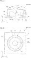
- a joined body 100 has an optical device 10 as a first member and a substrate 20 as a second member.
- the optical device 10 and the substrate 20 are laminated or stacked and bonded in the Z-axis direction vertical to an XY surface.
- a light emitting device 22 By arranging a light emitting device 22 to, e.g. , the substrate 20, the joined body 100 can be used as a light source unit 200.
- the optical device (first member) 10 is a member with optical transparency through which light within a wavelength range to be used can be transmitted, e.g. , a transparent member in a case where light within a visible light area is transmitted.
- the optical device 10 is formed of a thermoplastic resin as an organic material.
- the thermoplastic resin is melted with vibration energy generated by ultrasonic waves, using, for example, cyclo olefin polymer (COP), acrylic (PMMA), polycarbonate (PC), or the like.
- COP cyclo olefin polymer
- PMMA acrylic
- PC polycarbonate
- the optical device 10 has an approximately circular contour viewed in an optical axis OA direction.
- the optical device 10 has a lens element 10a and a supporting unit 10b that supports the lens element 10a from the periphery.
- the lens element 10a is, e.g., a both-convex aspherical lens, and has a first optical surface 11a and a second optical surface 11b.
- the supporting unit 10b has a plate-shaped flat part 12a and a ring-shaped frame part 12b that is extended in parallel with the optical axis OA from the outer periphery of the flat part 12a.
- Projected portions 12d are formed to an end surface 12c of the frame part 12b on the side of the substrate 20.
- the projected portions 12d are formed to a part for joining the optical device 10 and the substrate 20. In an example illustrated in the drawing, the projected portions 12d are double-circular.
- the arrangement of the projected portion 12d is not limited to the circular shape, and may be, e.g., linear-shaped in the direction vertical to the optical axis OA, radial with the optical axis OA as center, or dot-shaped.
- the cross-sectional shape of the projected portion 12d before the joining is not limited to be trapezoidal as illustrated in FIG. 3A , and may be, e.g., triangle, hemispherical, semi-elliptical, or the like.
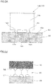
- the projected portions 12d and the substrate 20 are chemically joined via a molecular adhesive layer 30. As enlarged and illustrated in FIG.
- the tip of the projected portions 12d are melted with ultrasonic waves, and a melted mark 12h as the melted part locally joins the optical device 10 and the substrate 20.
- the optical device 10 is used as, e.g., a condenser lens.
- the substrate (second member) 20 is a transparent plate-shaped member with optical transparency, and a glass substrate made of glass as an inorganic material.
- the optical device 10 is joined to a first surface 20a of the substrate 20.
- the light emitting device 22 is arranged to a second surface 20b of the substrate 20.
- the center of the light emitting device 22 is arranged on the optical axis OA of the optical device 10.
- the light emitting device 22 e.g., an organic EL, an LED device, or the like is used.
- the first surface 20a as a surface facing the optical device 10 is subjected to surface processing for activating molecules in advance.
- the surface processing is partly or wholly performed to the first surface 20a.
- the surface processing or treatment e.g., corona processing, plasma processing, ozone processing, ultraviolet (UV) processing, or the like is performed.
- the bonding force between the optical device 10 and the substrate 20 can be more strengthened.
- the end surface 12c (particularly, tip of the projected portion 12d) of the frame part 12b in the optical device 10 may also be subjected to the surface processing for activating the molecules. Both the substrate 20 and the optical device 10 are subjected to the surface processing, thereby further strengthening the bonding force.
- the above surface processing may not be given to the substrate 20 and the optical device 10, and the surface may be only wiped and cleaned with isopropyl alcohol (IPA) or the like.
- IPA isopropyl alcohol
- the molecular adhesive layer 30 is arranged between the optical device 10 and the substrate 20, specifically, on the first surface 20a of the substrate 20.
- the molecular adhesive layer 30 may also be arranged to a position corresponding to the frame part 12b of the optical device 10, or the whole first surface 20a of the substrate 20.
- the molecular adhesive layer 30 includes a single member of an adhesive with covalent bond to both the optical device 10 and the substrate 20, and does not include another adhesive member.
- FIG. 1A or the like illustrates that, for convenience of the description, the molecular adhesive layer 30 has the thickness. However, actually, the molecular adhesive layer 30 has a molecule size, and does not need to consider the hardening and contraction of the adhesive. As illustrated in FIG.
- the substrate 20 and the molecular adhesive layer 30 are bonded with covalent bond G1 through hydrolysis reaction and condensation reaction of a hydrolyzable group of the molecular adhesive.
- the optical device 10 and the molecular adhesive layer 30 are bonded with covalent bond G2 through a predetermined reaction of an organic functional group of the molecular adhesive.
- the molecular adhesive forming the molecular adhesive layer 30 for example, an adhesive containing silanol or the like, specifically, a silane coupling agent or the like is used.
- the optical device 10 is locally melted with ultrasonic waves, thereby being joined to the substrate 20 at portions of the projected portions 12d via the molecular adhesive layer 30. That is, only portions to be bonded of the optical device 10 and the substrate 20 are bonded. With ultrasonic waves, heat is generated in a joining interface between the optical device 10 and the substrate 20, and the resin is melted. As a result, the molecular adhesive layer 30 is chemically reacted, and is chemically bonded to the optical device 10 and the substrate 20.
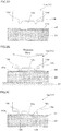
- the optical device 10 as the first member is formed.
- a forming method injection forming or molding, mold forming, or the like is used.
- the projected portion 12d is formed to the end surface 12c of the frame part 12b in the optical device 10.
- the substrate 20 as the second member is prepared.
- the first surface 20a of the substrate 20 is subjected to the surface processing for activating molecules, specifically, corona processing, plasma processing, ozone processing, ultraviolet (UV) processing, or the like.
- the first surface 20a is coated with the molecular adhesive to form the molecular adhesive layer 30.
- the silane coupling agent is dissolved in water, organic solvent, or the like, which is applied to the whole first surface 20a of the substrate 20 or a predetermined part including an area facing the projected portion 12d with a method such as dipping, spraying, spin coating, or the like, and is dried.
- the light emitting device 22 is attached to the second surface 20b of the substrate 20 (refer to FIG. 4 ). In this case, preferably, the light emitting device 22 is attached to the substrate 20 before executing the processing.
- the first surface 20a may be subjected to the surface processing for activating the molecules before forming the molecular adhesive layer 30 or after the formation thereof.
- the surface processing is performed after forming the molecular adhesive layer 30, the surface of the molecular adhesive layer 30 can be subjected to the surface processing, or the surface of the tip of the projected portion 12d or the like can also be subjected to the surface processing.
- the optical device 10 and the substrate 20 are joined with ultrasonic waves.
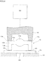
- An ultrasonic-waves welding machine is used for joining (refer to FIG. 4 ).
- the substrate 20 is fixed onto a supporting base 51 of the ultrasonic-waves welding machine.
- the optical device 10 may be fixed from a side surface in a state of being positioned on the first surface 20a of the substrate 20.
- a tool horn 52 of the ultrasonic-waves welding machine is pressed to an end surface 10s of the optical device 10 from the direction of the optical axis OA.
- Pressing force from the direction of the optical axis OA is a degree (e.g., 1 N to 100 N) for sufficiently transmitting ultrasonic vibration to the optical device 10.
- a frequency of ultrasonic waves is, e.g., 10 kHz to 30 kHz
- joining time is, e.g., 0.1 sec to 5 sec.
- an ultrasonic-waves oscillator 53 of the ultrasonic-waves welding machine is operated, thereby generating heat in a joining interface (specifically, the tip and the periphery of the projected portion 12d) between the optical device 10 and the substrate 20.
- a joining interface specifically, the tip and the periphery of the projected portion 12d
- the resin of the tip of the projected portion 12d of the optical device 10 is melted.
- the thermoplastic resin of the optical device 10, glass of the substrate 20, and the silane coupling agent as the molecular adhesive layer 30 are chemically reacted, and are chemically bonded.
- the resin is melted at a contact portion with the substrate 20. Therefore, only a part of the projected portion 12d is locally joined.
- the contact part between the optical device 10 and the substrate 20 is local and the amount of the resin melted in the projected portion 12d is thus miner. Thermal influence at the hardening and contraction time or the melting time is extremely small.
- the ultrasonic vibration ends and the cooling is performed, thereby finishing the joined body 100 obtained by joining the optical device 10 and the substrate 20 or the light source unit 200.
- a series of processes of the surface processing, the formation of the molecular adhesive layer 30, and the joining with ultrasonic waves may be performed under the same atmosphere (e.g., under inert atmosphere), or may not be performed under the same atmosphere if an effect of the surface processing is not lost.
- the thermoplastic resin and the inorganic material that is, mutually different members (the optical device 10 as the first member and the substrate 20 as the second member) can be joined by chemical bond (specifically, covalent bond) using the molecular adhesive layer 30.
- the molecular adhesive layer 30 can obtain stable bonding force because, e.g. , only a silane coupling agent, that is, another joining member is not mixed. Further, the molecular adhesive layer 30 is covalently bonded and thus the contraction and the like are not generated at the hardening time, as compared with an adhesive layer that is not covalently bonded and the positional shift between the optical device 10 and the substrate 20 can be prevented.
- the joining via the molecular adhesive layer 30 does not need fixing until finishing hardening reaction like an adhesive layer that is not covalently bonded, and can be performed for a relatively short time by appropriately setting a condition such as joining temperature or a cooling method. Furthermore, since the optical device 10 and the substrate 20 are joined by using ultrasonic waves, a target portion can be locally (or selectively) joined. Since the amount of thermoplastic resin melted at the joining time is minute, the amount of contraction of the melted resin is much smaller than the amount of contraction in a case of hardening an adhesive that is wholly liquid, and thermal influence is extremely small at the hardening and contraction time or the melting time. Therefore, it is hard to exert influence on the positional shift between the optical device 10 and the substrate 20.
- the optical device 10 as the first member has the projected portion 12d on the side of the substrate 20 as the second member at least before the joining.
- the projected portion 12d is formed to a portion to be joined. Before the joining, the projected portion 12d comes into contact with the substrate 20, and the projected portion 12d is melted with ultrasonic waves, thereby joining only the portion to be bonded. Further, if the joining is performed between, e.g. , the plurality of projected portions 12d so as to sandwich an air layer, it is possible to reduce the influence of the difference in thermal expansion between the optical device 10 and the substrate 20.
- the optical device 10 as the first member and the substrate 20 as the second member are transparent members with optical transparency, the resin is melted by using ultrasonic waves and a joining state is therefore preferable. That is, the joining can be performed, irrespective of colors of the optical device 10 and the substrate 20, and both the optical device 10 and the substrate 20 are not limited to transparent members, and may also use black members.
- a member with optical transparency, for which distortion is not preferable, also with the environment resistance is suitable for joining with, in particular, a member with high importance about the positional shift is suitable. Even with the joined body 100 formed by combining the optical device 10 made of the resin as the first member and the substrate 20 made of the glass as the second member, a preferable joining state can be accomplished.
- Example 1 the first member was formed as a sample with injection molding by using a thermoplastic resin.
- the first member was not the optical device but a quadratic-prism member.
- the height was 1 mm
- the width was 1 mm
- the length was 5 mm.
- the projected portion was formed by aligning two columns with triangular cross-section, and the interval between the tips of the two projected portions was 3 mm.
- Cyclo olefin polymer (COP) ZEONEX E48R (manufactured by ZEONEX CORPORATION)
- PC polycarbonate
- PC1600 manufactured by TAKIRON Co.
- thermoplastic resin a glass plate was used.
- a member that was subjected to the surface processing for activating molecules and a member that was not subj ected to the surface processing for activating molecules there were prepared a member that was subjected to the surface processing for activating molecules and a member that was not subj ected to the surface processing for activating molecules.
- UV ozone cleaning or plasma cleaning was performed. The UV ozone cleaning was performed under conditions that a UV wavelength (185-253 nm) was used, an irradiation distance was 10 mm, and cleaning time was 5 min.
- the plasma cleaning was performed under conditions that pressure was 10 Pa, an output was 150 W, and cleaning time was 10 sec. Note that in the second member that was not subjected to the surface processing for activating molecules, the first surface was wiped out with IPA and was cleaned. After the processing, the first surface of the second member was coated with a molecular adhesive, and the molecular adhesive layer was formed.
- An adhesive containing silanol silane coupling agent SZ-6300 (manufactured by Dow Corning Toray Co., Ltd.) or a silane coupling agent Z-6011 (manufactured by Dow Corning Toray Co. , Ltd.) was used for the molecular adhesive.
- the first member and the second member were joined with ultrasonic waves, thereby producing the joined body.
- An ultrasonic-waves welding machine (SONOPET ⁇ 600S (manufactured by SEIDENSHA ELECTRONICS CO., LTD.) was used for the joining. The joining was performed under conditions that the frequency of ultrasonic waves was 30 kHz, the load of the tool horn 52 was 100 N, and the joining time was 0.3 sec.
- Table 1 shows a joining state of the first member and the second member.
- a silane coupling agent SZ-6300 is expressed as "A”
- a silane coupling agent Z-6011 is expressed as "B”.
- Evaluation of the joining state of the joined body is determined with joining force at time for peeling or breaking of the first and second members. The joining force was measured by using a pull gauge while the second member was fixed, and the first member was chucked by using a jig and was vertically pulled up.
- the joined body has the joining force of 2N ⁇ F by joining the first and second members via the molecular adhesive layer with ultrasonic waves. Further, it can be understood that by performing the surface processing for activating molecules, the joining force of the joined body having the first and second members can be more strengthened. Note that, for the sake of comparison, the first member and the second member were adhered by using an acrylic-based photocurable adhesive, and the strength of the joined body was thus failing ("christcross" mark) irrespective of the presence or absence of the surface processing.
- joined body according to a second embodiment is obtained by partly changing the joined body according to the first embodiment, and matters that are not particularly described are similar to those according to the first embodiment.
- the optical devices 10 as the plurality of first members are locally joined to the substrate 20 as one second member via the molecular adhesive layer 30. Further, a light-shielding member 40 is arranged between the substrate 20 and the optical device 10.
- the light source unit 200 including the joined body 100 is used for, for example, a print head and the like.
- the optical device 10 has square contour viewed in the direction of the optical axis OA.
- the optical device 10 has the plurality of lens elements 10a and the supporting unit 10b that peripherally supports the plurality of lens elements 10a.
- the lens elements 10a are arranged like an array.
- the supporting unit 10b has the frame part 12b extended in the vertical direction to the flat part 12a from two facing sides of the plate-shaped flat part 12a.
- the projected portion 12d is formed to the end surface 12c of the frame part 12b.
- the plurality of light emitting devices 22 is arranged like an array at positions corresponding to the lens elements 10a of the optical device 10 on the second surface 20b of the substrate 20.
- the light-shielding member 40 is a plate-shaped member, and shields unnecessary light from the light emitting device 22.
- the light-shielding member 40 for example, a substrate made of a glass or a resin containing light-absorbing particles of black or the like, a metallic substrate coated to black, or the like is used.
- An opening 40a is formed to the light-shielding member 40 in a position corresponding to the lens element 10a of the optical device 10.
- the light-shielding member 40 is joined to the side of the substrate 20.
- the light-shielding member 40 may be adhered with an adhesive other than the molecular adhesive, the light-shielding member 40 may be joined by using ultrasonic waves depending on combination of materials, similarly to the joining of the optical device 10 and the substrate 20.
- the material of the light-shielding member 40 is resin different from the inorganic material as the material of the substrate 20, the joining is possible via a molecular adhesive layer 130.
- the optical devices 10 may be joined once with ultrasonic waves or the optical devices 10 may be aligned on the unit basis of one or several devices and be joined with ultrasonic waves individually at plural times.
- the joining using ultrasonic waves can be performed for a relatively short time. Therefore, if a plurality of optical devices (first members) 10 may be joined once or individually at plural times, the joining can be performed for a relatively short time, and the productivity is high.
- the light source unit 200 including the joined body 100 is arranged to an image forming unit 80 included in, e. g. , an electrophotographic printer as an image forming apparatus.
- the image forming unit 80 transfers toner for development to paper.
- a photosensitive member 81, a charge roller 82, a print head 83, a developing device 84, a transfer device 85, a cleaning device 86, and a neutralizing device 87 are arranged to the image forming unit 80.
- the light source unit 200 is arranged to the print head 83.
- the other members 82 to 87 are operated to the photosensitive member 81, thereby forming an image to paper PP.
- the light-shielding member 40 is not only joined to the side of the substrate 20, but may also be joined to the side of the optical device 10. In this case, even if a material of the light-shielding member 40 is any of resin, glass, and metal, the light-shielding member 40 can be joined via a molecular adhesive layer 230.
- joined body according to the third embodiment is obtained by partly changing the joined body according to the first embodiment, and matters that are not particularly described are similar to those according to the first embodiment.
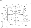
- the joined body 100 has not only the optical device 10 as the first member and the substrate 20 as the second member, but also an optical device 50 as a third member.
- the optical device 50 is overlapped and joined to the optical device 10, that is, in a state in which the optical device 50 is further joined to the optical device 10 to which the substrate 20 has been joined.
- the optical device 50 is a transparent member with optical transparency, similarly to the optical device 10, and is made of a thermoplastic resin as the organic material.
- the shape of the optical device 50 is similar to the shape of the optical device 10, but can be appropriately changed.
- the optical device 50 has a lens element 50a and a supporting unit 50b that peripherally supports the lens element 50a.
- the lens element 50a is, for example, a both-convex aspherical lens, and has a third optical surface 51a and a fourth optical surface 51b.
- the supporting unit 50b has a plainer plane part 52a and a circular frame part 52b extended from the plane part 52a in parallel with the optical axis OA.
- a projected portion 52d is formed to an end surface 52c of the frame part 52b on the side of the optical device 10. That is, in the optical device 50 (third member), the projected portion 52d is provided on the side of the optical device 10 (first member). Local melting with ultrasonic waves in melting with ultrasonic-wave welding enables resins to be welded.
- the local melting with ultrasonic waves enables local chemical joining of the projected portion 52d of the optical device 50 and the supporting unit 10b of the optical device 10 via a molecular adhesive layer 60.
- the joined body 100 wherein the two optical devices 10 and 50 are laminated or stacked onto the substrate 20.
- the plurality of optical devices 10 and 50 may be aligned to one substrate 20.
- joined body according to a fourth embodiment will be described. Note that the joined body according to the fourth embodiment is obtained by partly changing the joined body according to the first embodiment, and matters that are not particularly described are similar to those according to the first embodiment.
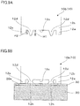
- leg portions 12e are formed to the end surface 12c of the frame part 12b on the side of the substrate 20.
- the projected portions 12d are arranged in a state of being sandwiched by the leg portions 12e.
- height H1 of the projected portions 12d is higher than height H2 of the leg portions 12e before the joining.
- the projected portions 12d have approximately the same height as that of the leg portions 12e in a state of being melted.
- the optical device 10 is more stably supported with the leg portions 12e.
- the position of the leg portions 12e can be appropriately changed by the shape of the optical device 10, for example, in a case of the optical device 10 having the plurality of lens elements 10a, the leg portions 12e may also be provided between the lens elements 10a.
- joined body according to a fifth embodiment will be described. Note that the joined body according to the fifth embodiment is obtained by partly changing the joined body according to the first embodiment, and matters that are not particularly described are similar to those according to the first embodiment.
- the optical device 10 as the first member and the substrate 20 as the second member are joined in a contact state with each other.
- the lens element 10a has a light guiding unit 11g on the side of the substrate 20, in place of the second optical surface 11b according to the first embodiment.
- the light guiding unit 11g is column-shaped, and has a flat surface 11c at the bottom end.
- the light guiding unit 11g may be cylinder or prismatic column-shaped, and may have a taper or not.
- a projected portion 11p is arranged to the flat surface 11c of the light guiding unit 11g.
- a light-shielding unit 11r for preventing entering of ambient light is formed to a side surface of the light guiding unit 11g.
- the light-shielding unit 11r is formed, for example, by adhering a black light-shielding film, forming a black light-shielding film, or performing emboss processing.
- the light guiding unit 11g corresponds to the individual lens elements 10a, and when the light emitting device 22 emits light in the light source unit 200 including the joined body 100, the light passes through the substrate 20, the light guiding unit 11g, and the lens element 10a, is emitted from the first optical surface 11a, and forms an image.
- the projected portion 11p is completely melted with ultrasonic waves, thereby joining the optical device 10 and the substrate 20 on the flat surface 11c in a contact state with each other.
- the resins in the joining part of the optical device 10 and the substrate 20 are melted with ultrasonic waves, and an interface of the optical device 10 and the substrate 20 is therefore integral, and does not disturb an optical path due to reflection loss.
- the projected portion may be formed at least before the joining, or may be completely melted after the joining, alternatively, only a part may be melted and another part may remain even after the joining.
- the plurality of optical devices 10 may also be aligned to one substrate 20.
- joined body according to a sixth embodiment is obtained by partly changing the joined body according to the first and fifth embodiments, and matters that are not particularly described are similar to those according to the first and fifth embodiments.
- liquid LQ is enclosed in sealed space formed between the optical device 10 as the first member and the substrate 20 as the second member.
- liquid resin material without an initiator for ultraviolet hardening or thermal hardening
- oil or the like is used.
- the lens element 10a has the light guiding unit 11g on the side of the substrate 20, in place of the second optical surface 11b according to the first embodiment.
- the light guiding unit 11g is column-shaped, and has a recessed portion 11k to be filled with the liquid LQ at the bottom end.
- the projected portion 11p is arranged to an outer circumferential portion 11m of the light guiding unit 11g.
- the light-shielding unit 11r for preventing the entering of ambient light is formed to a side surface of the light guiding unit 11g.
- the liquid LQ is filled to the recessed portion 11k before the joining, and the optical device 10 and the substrate 20 are joined in a sandwiching state of the liquid LQ therebetween.
- the substrate 20 is a plate-shaped. If a joining surface of the optical device 10 and the substrate 20 is large, warpage or the like can be generated in the substrate 20. Therefore, the joining surface is limited to the outer circumference, and for example, the liquid LQ with the same refractive index as that of the optical device 10 is enclosed to the inside thereof, thereby preventing the disturbance of an optical path due to reflection loss.
- the plurality of optical devices 10 may be arranged to one substrate 20.
- the joined body and the like according to the embodiments have been described above.
- the joined body and the like according to the present invention are not limited to the foregoing.
- the shape and size of the optical devices 10 and 50 can be appropriately changed according to applications and functions.
- the lens element 10a may have the light guiding unit 11g as illustrated in FIG. 9A or the like.
- the first member and the second member are not limited to the optical device 10 and the substrate 20, respectively, and can be appropriately changed according to applications.
- the projected portions 12d and 11p may not be provided for the optical device 10, but, for example, a fine wiring may be formed by using wire bonding or the like for the substrate 20 and be set as a vibration core of ultrasonic waves.
- the example has been given that the plurality of optical devices 10 is arranged to one substrate 20.
- the optical device 10 is not limited to an array-like optical device, and the plurality of optical devices 10 having one lens element 10a as described in the first embodiment may be arranged or a plurality of lamination of the optical devices 10 and 50 as described in the third embodiment may be arranged.
- the joined body 100 according to the second embodiment may be cut to form individual pieces of the joined body.
Landscapes
- Engineering & Computer Science (AREA)
- Mechanical Engineering (AREA)
- Chemical & Material Sciences (AREA)
- Inorganic Chemistry (AREA)
- Chemical Kinetics & Catalysis (AREA)
- General Chemical & Material Sciences (AREA)
- Lining Or Joining Of Plastics Or The Like (AREA)
Abstract

Description
- The present invention relates to a joined body including a thermoplastic resin and an inorganic material and a method for producing the joined body.
- As a method for joining an organic material and another member, there is a method for welding thermoplastic resins with ultrasonic waves (refer to, e.g. , Patent Literature 1). In addition, as another method for joining an organic material and another member, there is a method for joining an organic base material and an inorganic base material by using a resin containing a silane coupling agent or a primer containing a silane coupling agent (refer to, e.g., Patent Literatures 2 and 3). Further, as another method for joining an organic material and another member, there is a method for joining only a target position with a method for joining different materials by using laser beams (refer to, e.g., Patent Literature 4).
- However, with the joining method according to Patent Literature 1, parts in which ultrasonic waves are strongly operated each other in a target resin are melted to integrally bond the parts, and the method is not suitable for joining members containing a resin material at different melting points or members different from a resin.
- Further, with the joining methods according to Patent Literatures 2 and 3, since there is a composition other than the base material on a joining interface, the environmental resistance of a joining member (specifically, resin or primer) should be considered in addition to the environmental resistance of the base material. For example, in an aspect of hygroscopicity, if the hygroscopicity of the joining member is higher than that of the inorganic base material, there is danger that the joining member might swell and a joined portion might be peeled. Further, if the hygroscopicity of the joining member is low, there is danger that the joining member might be broken because it is not resistant against a swelling load of the organic base material. Furthermore, in order to replicate a preferable state of joining in mass production, each content of the silane coupling agent and the joining member at time of mixing thereof should be managed. In addition, crimping methods with surfaces according to Patent Literatures 2 and 3 are suitable for joining a sheet or a film, but it is hard to partially join a shaped part because heat cannot be uniformly conducted.
- Moreover, with the joining method according to
Patent Literature 4, the joining is limited to that of a material for absorbing laser beams and a material through which laser beams are transmitted, and it is hard to join, e.g., transparent members or black members. -
- [Patent Literature 1]
WO 2002/084407 - [Patent Literature 2] Japanese Patent Laid-Open No.
2013-98377 - [Patent Literature 3]
WO 1998/15401 - [Patent Literature 4] Japanese Patent Laid-OpenNo.
2011-235570 - It is an object of the present invention to provide a joined body that is formed by partially joining mutually different members, i.e. , a thermoplastic resin and an inorganic material in a preferable joining state.
- Further, it is another object of the present invention to provide a method for producing such a joined body.
- In order to solve the aforementioned problems, a joined body according to the present invention includes a first member made of a thermoplastic resin and a second member made of an inorganic material, a molecular adhesive layer is provided between the first member and the second member, and the first member is locally melted with ultrasonic waves, thereby chemically being joined to the second member via the molecular adhesive layer. Herein, the molecular adhesive layer includes a single member of an adhesive that is covalently bonded to both the first and second members, and does not include another adhesive member.
- With the joined body, chemical bond (specifically, covalent bond) using the molecular adhesive layer enables joining of mutually different members, i.e., the thermoplastic resin and the inorganic material. The molecular adhesive can obtain stable bonding force because another joining member is not mixed, e.g., only a silane coupling agent. Further, the molecular adhesive layer is covalently bonded, and the positional shift between the first and second members can therefore be prevented without generating contraction or the like at hardening time, as compared with an adhesive layer that is not covalently bonded. Further, it is not required that the joining via the molecular adhesive layer is fixed until finishing hardening reaction like the adhesive layer that is not covalently bonded, and the joining can be performed for a relatively short time by appropriately setting a condition such as joining temperature or a cooling method. Furthermore, since the first and second members are joined by using ultrasonic waves, local joining is possible. Because of a minute amount of the thermoplastic resin melted at the joining time, the amount of contraction of the melted resin is extremely smaller than the amount of contraction in a case of hardening an adhesive that is wholly liquid, and thermal influence at hardening and contraction time or melting time is extremely small. Therefore, it is hard to exert influence on the positional shift between the first and second members.
- With a method for producing a joined body according to the present invention, a molecular adhesive layer is arranged to a surface facing a first member made of a thermoplastic resin in a second member made of an inorganic material, and the first member is locally melted with ultrasonic waves and is chemically joined to the second member via the molecular adhesive layer.
- With the method for producing the joined body, it is possible to stably join mutually different members, i.e., the thermoplastic resin and the inorganic material by chemical bond (covalent bond) using the molecular adhesive layer. Further, contraction or the like is not generated in the molecular adhesive layer at the hardening time, and it is possible to prevent the positional shift between the first and second members. Further, the joining via the molecular adhesive layer can be performed for a relatively short time. Furthermore, since the first and second members are joined by using ultrasonic waves, local joining is possible. Because of a minute amount of the thermoplastic resin melted at the joining time, thermal influence at the hardening and contraction time or the melting time is extremely small, and it is hard to exert influence on the positional shift between the first and second members.
-
-
FIG. 1A is a cross-sectional view of a light source unit including a joined body according to a first embodiment, andFIG. 1B is a plan view of the joined body illustrated inFIG. 1A . -
FIG. 2A is a partially enlarged cross-sectional view of the joined body inFIG. 1 , andFIG. 2B is a diagram illustrating a connecting relationship among a first member, a molecular adhesive layer, and a second member. -
FIGS. 3A to 3C are diagrams illustrating a method for producing the joined body. -
FIG. 4 is a diagram illustrating joining with ultrasonic waves. -
FIG. 5A is a perspective view of a light source unit including a joined body according to a second embodiment,FIG. 5B is a cross-sectional view of the joined body illustrated inFIG. 5A viewed by an arrow AA, andFIG. 5C is a diagram illustrating a modified example of the light source unit inFIG. 5A . -
FIG. 6 is a diagram illustrating an image forming unit that includes the light source unit illustrated inFIG. 5A and the like. -
FIG. 7 is a cross-sectional view of a light source unit including a joined body according to a third embodiment. -
FIG. 8 is a partially enlarged cross-sectional view of a joined body according to a fourth embodiment,FIG. 8A is a diagram illustrating the first member before the joining, andFIG. 8B is a diagram illustrating the joined body after the joining. -
FIG. 9A is a cross-sectional view of a light source unit including a joined body according to a fifth embodiment, andFIG. 9B is a diagram illustrating the first member before the joining inFIG. 9A . -
FIG. 10 is a cross-sectional view of a light source unit including a joined body according to a sixth embodiment. -
FIG. 11 is a diagram illustrating a modified example of the light source unit including the joined body. - Hereinbelow, a description will be given of a joined body or the like according to a first embodiment of the present invention with reference to the drawings. As illustrated in
FIGS. 1A and 1B , a joinedbody 100 has anoptical device 10 as a first member and asubstrate 20 as a second member. Theoptical device 10 and thesubstrate 20 are laminated or stacked and bonded in the Z-axis direction vertical to an XY surface. By arranging alight emitting device 22 to, e.g. , thesubstrate 20, the joinedbody 100 can be used as alight source unit 200. - The optical device (first member) 10 is a member with optical transparency through which light within a wavelength range to be used can be transmitted, e.g. , a transparent member in a case where light within a visible light area is transmitted. The
optical device 10 is formed of a thermoplastic resin as an organic material. The thermoplastic resin is melted with vibration energy generated by ultrasonic waves, using, for example, cyclo olefin polymer (COP), acrylic (PMMA), polycarbonate (PC), or the like. Theoptical device 10 has an approximately circular contour viewed in an optical axis OA direction. Theoptical device 10 has alens element 10a and a supportingunit 10b that supports thelens element 10a from the periphery. Thelens element 10a is, e.g., a both-convex aspherical lens, and has a firstoptical surface 11a and a secondoptical surface 11b. The supportingunit 10b has a plate-shapedflat part 12a and a ring-shapedframe part 12b that is extended in parallel with the optical axis OA from the outer periphery of theflat part 12a. Projectedportions 12d are formed to anend surface 12c of theframe part 12b on the side of thesubstrate 20. The projectedportions 12d are formed to a part for joining theoptical device 10 and thesubstrate 20. In an example illustrated in the drawing, the projectedportions 12d are double-circular. Note that the arrangement of the projectedportion 12d is not limited to the circular shape, and may be, e.g., linear-shaped in the direction vertical to the optical axis OA, radial with the optical axis OA as center, or dot-shaped. Further, the cross-sectional shape of the projectedportion 12d before the joining is not limited to be trapezoidal as illustrated inFIG. 3A , and may be, e.g., triangle, hemispherical, semi-elliptical, or the like. The projectedportions 12d and thesubstrate 20 are chemically joined via a molecularadhesive layer 30. As enlarged and illustrated inFIG. 2A , the tip of the projectedportions 12d are melted with ultrasonic waves, and a meltedmark 12h as the melted part locally joins theoptical device 10 and thesubstrate 20. Theoptical device 10 is used as, e.g., a condenser lens. - The substrate (second member) 20 is a transparent plate-shaped member with optical transparency, and a glass substrate made of glass as an inorganic material. The
optical device 10 is joined to afirst surface 20a of thesubstrate 20. Further, as already described, in an example illustrated in the drawing, thelight emitting device 22 is arranged to asecond surface 20b of thesubstrate 20. The center of thelight emitting device 22 is arranged on the optical axis OA of theoptical device 10. As thelight emitting device 22, e.g., an organic EL, an LED device, or the like is used. - On the
substrate 20, before joining theoptical device 10, thefirst surface 20a as a surface facing theoptical device 10 is subjected to surface processing for activating molecules in advance. The surface processing is partly or wholly performed to thefirst surface 20a. As the surface processing or treatment, e.g., corona processing, plasma processing, ozone processing, ultraviolet (UV) processing, or the like is performed. As a consequence, the bonding force between theoptical device 10 and thesubstrate 20 can be more strengthened. Note that theend surface 12c (particularly, tip of the projectedportion 12d) of theframe part 12b in theoptical device 10 may also be subjected to the surface processing for activating the molecules. Both thesubstrate 20 and theoptical device 10 are subjected to the surface processing, thereby further strengthening the bonding force. Note that the above surface processing may not be given to thesubstrate 20 and theoptical device 10, and the surface may be only wiped and cleaned with isopropyl alcohol (IPA) or the like. - The molecular
adhesive layer 30 is arranged between theoptical device 10 and thesubstrate 20, specifically, on thefirst surface 20a of thesubstrate 20. The molecularadhesive layer 30 may also be arranged to a position corresponding to theframe part 12b of theoptical device 10, or the wholefirst surface 20a of thesubstrate 20. Herein, the molecularadhesive layer 30 includes a single member of an adhesive with covalent bond to both theoptical device 10 and thesubstrate 20, and does not include another adhesive member.FIG. 1A or the like illustrates that, for convenience of the description, the molecularadhesive layer 30 has the thickness. However, actually, the molecularadhesive layer 30 has a molecule size, and does not need to consider the hardening and contraction of the adhesive. As illustrated inFIG. 2B , thesubstrate 20 and the molecularadhesive layer 30 are bonded with covalent bond G1 through hydrolysis reaction and condensation reaction of a hydrolyzable group of the molecular adhesive. Theoptical device 10 and the molecularadhesive layer 30 are bonded with covalent bond G2 through a predetermined reaction of an organic functional group of the molecular adhesive. In the joinedbody 100 both of theoptical device 10 and thesubstrate 20 are covalently bonded (chemically bonded), and the environment resistance is thus high. As the molecular adhesive forming the molecularadhesive layer 30, for example, an adhesive containing silanol or the like, specifically, a silane coupling agent or the like is used. - As already described, in the joined
body 100, theoptical device 10 is locally melted with ultrasonic waves, thereby being joined to thesubstrate 20 at portions of the projectedportions 12d via the molecularadhesive layer 30. That is, only portions to be bonded of theoptical device 10 and thesubstrate 20 are bonded. With ultrasonic waves, heat is generated in a joining interface between theoptical device 10 and thesubstrate 20, and the resin is melted. As a result, the molecularadhesive layer 30 is chemically reacted, and is chemically bonded to theoptical device 10 and thesubstrate 20. - Hereinbelow, a description will be given of the method for producing the joined body. First, the
optical device 10 as the first member is formed. As a forming method, injection forming or molding, mold forming, or the like is used. As illustrated inFIG. 3A , the projectedportion 12d is formed to theend surface 12c of theframe part 12b in theoptical device 10. - Next, the
substrate 20 as the second member is prepared. Thefirst surface 20a of thesubstrate 20 is subjected to the surface processing for activating molecules, specifically, corona processing, plasma processing, ozone processing, ultraviolet (UV) processing, or the like. Thereafter, thefirst surface 20a is coated with the molecular adhesive to form the molecularadhesive layer 30. Specifically, the silane coupling agent is dissolved in water, organic solvent, or the like, which is applied to the wholefirst surface 20a of thesubstrate 20 or a predetermined part including an area facing the projectedportion 12d with a method such as dipping, spraying, spin coating, or the like, and is dried. In a case where the joinedbody 100 is used for application of thelight source unit 200, thelight emitting device 22 is attached to thesecond surface 20b of the substrate 20 (refer toFIG. 4 ). In this case, preferably, thelight emitting device 22 is attached to thesubstrate 20 before executing the processing. As mentioned above, thefirst surface 20a may be subjected to the surface processing for activating the molecules before forming the molecularadhesive layer 30 or after the formation thereof. In a case where the surface processing is performed after forming the molecularadhesive layer 30, the surface of the molecularadhesive layer 30 can be subjected to the surface processing, or the surface of the tip of the projectedportion 12d or the like can also be subjected to the surface processing. - Next, as illustrated in
FIG. 3B or the like, theoptical device 10 and thesubstrate 20 are joined with ultrasonic waves. An ultrasonic-waves welding machine is used for joining (refer toFIG. 4 ). Thesubstrate 20 is fixed onto a supportingbase 51 of the ultrasonic-waves welding machine. Theoptical device 10 may be fixed from a side surface in a state of being positioned on thefirst surface 20a of thesubstrate 20. Thereafter, as illustrated inFIG. 4 , atool horn 52 of the ultrasonic-waves welding machine is pressed to anend surface 10s of theoptical device 10 from the direction of the optical axis OA. Pressing force from the direction of the optical axis OA is a degree (e.g., 1 N to 100 N) for sufficiently transmitting ultrasonic vibration to theoptical device 10. Further, a frequency of ultrasonic waves is, e.g., 10 kHz to 30 kHz, and joining time is, e.g., 0.1 sec to 5 sec. As illustrated inFIG. 3B , in a state in which theoptical device 10 is laminated or stacked on thesubstrate 20, the projectedportion 12d of theoptical device 10 first comes into contact with thesubstrate 20. As illustrated inFIGS. 3B and4 , an ultrasonic-waves oscillator 53 of the ultrasonic-waves welding machine is operated, thereby generating heat in a joining interface (specifically, the tip and the periphery of the projectedportion 12d) between theoptical device 10 and thesubstrate 20. As illustrated inFIG. 3C , the resin of the tip of the projectedportion 12d of theoptical device 10 is melted. In this case, the thermoplastic resin of theoptical device 10, glass of thesubstrate 20, and the silane coupling agent as the molecularadhesive layer 30 are chemically reacted, and are chemically bonded. The resin is melted at a contact portion with thesubstrate 20. Therefore, only a part of the projectedportion 12d is locally joined. The contact part between theoptical device 10 and thesubstrate 20 is local and the amount of the resin melted in the projectedportion 12d is thus miner. Thermal influence at the hardening and contraction time or the melting time is extremely small. The ultrasonic vibration ends and the cooling is performed, thereby finishing the joinedbody 100 obtained by joining theoptical device 10 and thesubstrate 20 or thelight source unit 200. Note that a series of processes of the surface processing, the formation of the molecularadhesive layer 30, and the joining with ultrasonic waves may be performed under the same atmosphere (e.g., under inert atmosphere), or may not be performed under the same atmosphere if an effect of the surface processing is not lost. - With the above-described joined body, the thermoplastic resin and the inorganic material, that is, mutually different members (the
optical device 10 as the first member and thesubstrate 20 as the second member) can be joined by chemical bond (specifically, covalent bond) using the molecularadhesive layer 30. The molecularadhesive layer 30 can obtain stable bonding force because, e.g. , only a silane coupling agent, that is, another joining member is not mixed. Further, the molecularadhesive layer 30 is covalently bonded and thus the contraction and the like are not generated at the hardening time, as compared with an adhesive layer that is not covalently bonded and the positional shift between theoptical device 10 and thesubstrate 20 can be prevented. Further, the joining via the molecularadhesive layer 30 does not need fixing until finishing hardening reaction like an adhesive layer that is not covalently bonded, and can be performed for a relatively short time by appropriately setting a condition such as joining temperature or a cooling method. Furthermore, since theoptical device 10 and thesubstrate 20 are joined by using ultrasonic waves, a target portion can be locally (or selectively) joined. Since the amount of thermoplastic resin melted at the joining time is minute, the amount of contraction of the melted resin is much smaller than the amount of contraction in a case of hardening an adhesive that is wholly liquid, and thermal influence is extremely small at the hardening and contraction time or the melting time. Therefore, it is hard to exert influence on the positional shift between theoptical device 10 and thesubstrate 20. - Further, the
optical device 10 as the first member has the projectedportion 12d on the side of thesubstrate 20 as the second member at least before the joining. In this case, the projectedportion 12d is formed to a portion to be joined. Before the joining, the projectedportion 12d comes into contact with thesubstrate 20, and the projectedportion 12d is melted with ultrasonic waves, thereby joining only the portion to be bonded. Further, if the joining is performed between, e.g. , the plurality of projectedportions 12d so as to sandwich an air layer, it is possible to reduce the influence of the difference in thermal expansion between theoptical device 10 and thesubstrate 20. - Furthermore, even if the
optical device 10 as the first member and thesubstrate 20 as the second member are transparent members with optical transparency, the resin is melted by using ultrasonic waves and a joining state is therefore preferable. That is, the joining can be performed, irrespective of colors of theoptical device 10 and thesubstrate 20, and both theoptical device 10 and thesubstrate 20 are not limited to transparent members, and may also use black members. - Moreover, regarding the joining in which the resin is melted and which is performed via the molecular
adhesive layer 30, a member with optical transparency, for which distortion is not preferable, also with the environment resistance is suitable for joining with, in particular, a member with high importance about the positional shift is suitable. Even with the joinedbody 100 formed by combining theoptical device 10 made of the resin as the first member and thesubstrate 20 made of the glass as the second member, a preferable joining state can be accomplished. - Hereinbelow, a description will be given of Example 1 of the present embodiment. In this Example 1, the first member was formed as a sample with injection molding by using a thermoplastic resin. For sake of simplification, the first member was not the optical device but a quadratic-prism member. Regarding dimensions of a projected portion, the height was 1 mm, the width was 1 mm, and the length was 5 mm. The projected portion was formed by aligning two columns with triangular cross-section, and the interval between the tips of the two projected portions was 3 mm. Cyclo olefin polymer (COP) (ZEONEX E48R (manufactured by ZEONEX CORPORATION)), polycarbonate (PC) (PC1600 (manufactured by TAKIRON Co. , LTD.)), and acrylic resin (PMMA) (Deraglass (trademark) K (manufactured by ASAHIKASEI TECHNOPLUS Corporation) were used for the thermoplastic resin. As the second member, a glass plate was used. For a first surface as the joining interface of the second member with the first member, there were prepared a member that was subjected to the surface processing for activating molecules and a member that was not subj ected to the surface processing for activating molecules. In the surface processing for activating molecules, UV ozone cleaning or plasma cleaning was performed. The UV ozone cleaning was performed under conditions that a UV wavelength (185-253 nm) was used, an irradiation distance was 10 mm, and cleaning time was 5 min. The plasma cleaning was performed under conditions that pressure was 10 Pa, an output was 150 W, and cleaning time was 10 sec. Note that in the second member that was not subjected to the surface processing for activating molecules, the first surface was wiped out with IPA and was cleaned. After the processing, the first surface of the second member was coated with a molecular adhesive, and the molecular adhesive layer was formed. An adhesive containing silanol (silane coupling agent SZ-6300 (manufactured by Dow Corning Toray Co., Ltd.) or a silane coupling agent Z-6011 (manufactured by Dow Corning Toray Co. , Ltd.)) was used for the molecular adhesive. Thereafter, the first member and the second member were joined with ultrasonic waves, thereby producing the joined body. An ultrasonic-waves welding machine (SONOPET∑600S (manufactured by SEIDENSHA ELECTRONICS CO., LTD.) was used for the joining. The joining was performed under conditions that the frequency of ultrasonic waves was 30 kHz, the load of the
tool horn 52 was 100 N, and the joining time was 0.3 sec. - Table 1 shows a joining state of the first member and the second member. In Table 1, regarding the molecular adhesive, a silane coupling agent SZ-6300 is expressed as "A", and a silane coupling agent Z-6011 is expressed as "B". Evaluation of the joining state of the joined body is determined with joining force at time for peeling or breaking of the first and second members. The joining force was measured by using a pull gauge while the second member was fixed, and the first member was chucked by using a jig and was vertically pulled up. Measuring results are evaluated that ON≤F<2N is failing ("christcross" mark), 2N≤F<25N is passing ("triangle" mark), 25N≤F<50N is good ("single-circle" mark), and 50N≤F is excellent ("double-circle" mark) where F is the joining force.
[Table 1] Processing of joining interface Molecular Adhesive 1st member Evaluation None A COP Δ None A PC Δ None A PMMA Δ None B COP Δ None B PC Δ None B PMMA Δ UV ozone cleaning A COP Δ UV ozone cleansing A PC ⊚ UV ozone cleaning A PMMA ⊚ UV ozone cleaning B COP ○ UV ozone cleaning B PC ⊚ UV ozone cleaning B PMMA ⊚ Plasma cleanig A COP ○ Plasma cleanig A PC ⊚ Plasma cleanig A PMMA ⊚ Plasma cleanig B COP ⊚ Plasma cleanig B PC ⊚ Plasma cleanig B PMMA ⊚ - As illustrated in Table 1, it can be understood that the joined body has the joining force of 2N≤F by joining the first and second members via the molecular adhesive layer with ultrasonic waves. Further, it can be understood that by performing the surface processing for activating molecules, the joining force of the joined body having the first and second members can be more strengthened. Note that, for the sake of comparison, the first member and the second member were adhered by using an acrylic-based photocurable adhesive, and the strength of the joined body was thus failing ("christcross" mark) irrespective of the presence or absence of the surface processing.
- Hereinbelow, a description will be given of a joined body according to a second embodiment. Note that the joined body according to the second embodiment is obtained by partly changing the joined body according to the first embodiment, and matters that are not particularly described are similar to those according to the first embodiment.
- As illustrated in
FIGS. 5A and 5B , in the present embodiment, theoptical devices 10 as the plurality of first members are locally joined to thesubstrate 20 as one second member via the molecularadhesive layer 30. Further, a light-shieldingmember 40 is arranged between thesubstrate 20 and theoptical device 10. Thelight source unit 200 including the joinedbody 100 is used for, for example, a print head and the like. - One
optical device 10 has square contour viewed in the direction of the optical axis OA. Theoptical device 10 has the plurality oflens elements 10a and the supportingunit 10b that peripherally supports the plurality oflens elements 10a. Thelens elements 10a are arranged like an array. The supportingunit 10b has theframe part 12b extended in the vertical direction to theflat part 12a from two facing sides of the plate-shapedflat part 12a. The projectedportion 12d is formed to theend surface 12c of theframe part 12b. - The plurality of light emitting
devices 22 is arranged like an array at positions corresponding to thelens elements 10a of theoptical device 10 on thesecond surface 20b of thesubstrate 20. - The light-shielding
member 40 is a plate-shaped member, and shields unnecessary light from thelight emitting device 22. As the light-shieldingmember 40, for example, a substrate made of a glass or a resin containing light-absorbing particles of black or the like, a metallic substrate coated to black, or the like is used. Anopening 40a is formed to the light-shieldingmember 40 in a position corresponding to thelens element 10a of theoptical device 10. The light-shieldingmember 40 is joined to the side of thesubstrate 20. Although the light-shieldingmember 40 may be adhered with an adhesive other than the molecular adhesive, the light-shieldingmember 40 may be joined by using ultrasonic waves depending on combination of materials, similarly to the joining of theoptical device 10 and thesubstrate 20. For example, if the material of the light-shieldingmember 40 is resin different from the inorganic material as the material of thesubstrate 20, the joining is possible via a molecularadhesive layer 130. - In the manufacturing of the joined
body 100, in a state in which the plurality ofoptical devices 10 is all aligned on thefirst surface 20a of thesubstrate 20, theoptical devices 10 may be joined once with ultrasonic waves or theoptical devices 10 may be aligned on the unit basis of one or several devices and be joined with ultrasonic waves individually at plural times. - With the above-mentioned joined
body 100, the joining using ultrasonic waves can be performed for a relatively short time. Therefore, if a plurality of optical devices (first members) 10 may be joined once or individually at plural times, the joining can be performed for a relatively short time, and the productivity is high. - As illustrated in
FIG. 6 , thelight source unit 200 including the joinedbody 100 is arranged to animage forming unit 80 included in, e. g. , an electrophotographic printer as an image forming apparatus. Theimage forming unit 80 transfers toner for development to paper. Aphotosensitive member 81, acharge roller 82, aprint head 83, a developingdevice 84, atransfer device 85, acleaning device 86, and a neutralizingdevice 87 are arranged to theimage forming unit 80. Among those, thelight source unit 200 is arranged to theprint head 83. In theimage forming unit 80, theother members 82 to 87 are operated to thephotosensitive member 81, thereby forming an image to paper PP. - Note that, in the above-described embodiment, as illustrated in
FIG. 5C , the light-shieldingmember 40 is not only joined to the side of thesubstrate 20, but may also be joined to the side of theoptical device 10. In this case, even if a material of the light-shieldingmember 40 is any of resin, glass, and metal, the light-shieldingmember 40 can be joined via a molecularadhesive layer 230. - Hereinbelow, a description will be given of a joined body according to a third embodiment. Note that the joined body according to the third embodiment is obtained by partly changing the joined body according to the first embodiment, and matters that are not particularly described are similar to those according to the first embodiment.
- As illustrated in
FIG. 7 , in the present embodiment, the joinedbody 100 has not only theoptical device 10 as the first member and thesubstrate 20 as the second member, but also anoptical device 50 as a third member. Theoptical device 50 is overlapped and joined to theoptical device 10, that is, in a state in which theoptical device 50 is further joined to theoptical device 10 to which thesubstrate 20 has been joined. Theoptical device 50 is a transparent member with optical transparency, similarly to theoptical device 10, and is made of a thermoplastic resin as the organic material. In an example illustrated in the diagram, the shape of theoptical device 50 is similar to the shape of theoptical device 10, but can be appropriately changed. Theoptical device 50 has alens element 50a and a supportingunit 50b that peripherally supports thelens element 50a. Thelens element 50a is, for example, a both-convex aspherical lens, and has a thirdoptical surface 51a and a fourthoptical surface 51b. The supportingunit 50b has aplainer plane part 52a and acircular frame part 52b extended from theplane part 52a in parallel with the optical axis OA. A projectedportion 52d is formed to anend surface 52c of theframe part 52b on the side of theoptical device 10. That is, in the optical device 50 (third member), the projectedportion 52d is provided on the side of the optical device 10 (first member). Local melting with ultrasonic waves in melting with ultrasonic-wave welding enables resins to be welded. However, here, the local melting with ultrasonic waves enables local chemical joining of the projectedportion 52d of theoptical device 50 and the supportingunit 10b of theoptical device 10 via a molecularadhesive layer 60. As a consequence, it is possible to obtain the joinedbody 100 wherein the twooptical devices substrate 20. - Note that also in the present embodiment, like the second embodiment, the plurality of
optical devices substrate 20. - Hereinbelow, a joined body according to a fourth embodiment will be described. Note that the joined body according to the fourth embodiment is obtained by partly changing the joined body according to the first embodiment, and matters that are not particularly described are similar to those according to the first embodiment.
- As illustrated in
FIGS. 8A and 8B , in the present embodiment, not only the projectedportions 12d but alsoleg portions 12e are formed to theend surface 12c of theframe part 12b on the side of thesubstrate 20. The projectedportions 12d are arranged in a state of being sandwiched by theleg portions 12e. As illustrated inFIG. 8A , height H1 of the projectedportions 12d is higher than height H2 of theleg portions 12e before the joining. On the other hand, as illustrated inFIG. 8B , the projectedportions 12d have approximately the same height as that of theleg portions 12e in a state of being melted. At the joining time, if the projectedportions 12d are melted with ultrasonic waves and application of ultrasonic waves ends when theleg portions 12e come into contact with thesubstrate 20, theoptical device 10 is more stably supported with theleg portions 12e. Note that the position of theleg portions 12e can be appropriately changed by the shape of theoptical device 10, for example, in a case of theoptical device 10 having the plurality oflens elements 10a, theleg portions 12e may also be provided between thelens elements 10a. - Hereinbelow, a joined body according to a fifth embodiment will be described. Note that the joined body according to the fifth embodiment is obtained by partly changing the joined body according to the first embodiment, and matters that are not particularly described are similar to those according to the first embodiment.
- As illustrated in
FIG. 9A , in the present embodiment, theoptical device 10 as the first member and thesubstrate 20 as the second member are joined in a contact state with each other. - In the
optical device 10, thelens element 10a has alight guiding unit 11g on the side of thesubstrate 20, in place of the secondoptical surface 11b according to the first embodiment. Thelight guiding unit 11g is column-shaped, and has aflat surface 11c at the bottom end. Thelight guiding unit 11g may be cylinder or prismatic column-shaped, and may have a taper or not. As illustrated inFIG. 9B , a projectedportion 11p is arranged to theflat surface 11c of thelight guiding unit 11g. Further, a light-shieldingunit 11r for preventing entering of ambient light is formed to a side surface of thelight guiding unit 11g. The light-shieldingunit 11r is formed, for example, by adhering a black light-shielding film, forming a black light-shielding film, or performing emboss processing. Thelight guiding unit 11g corresponds to theindividual lens elements 10a, and when thelight emitting device 22 emits light in thelight source unit 200 including the joinedbody 100, the light passes through thesubstrate 20, thelight guiding unit 11g, and thelens element 10a, is emitted from the firstoptical surface 11a, and forms an image. - In the joining of the
optical device 10 as the first member and thesubstrate 20 as the second member, the projectedportion 11p is completely melted with ultrasonic waves, thereby joining theoptical device 10 and thesubstrate 20 on theflat surface 11c in a contact state with each other. The resins in the joining part of theoptical device 10 and thesubstrate 20 are melted with ultrasonic waves, and an interface of theoptical device 10 and thesubstrate 20 is therefore integral, and does not disturb an optical path due to reflection loss. As will be obvious from the present embodiment and the above-mentioned respective embodiments, the projected portion may be formed at least before the joining, or may be completely melted after the joining, alternatively, only a part may be melted and another part may remain even after the joining. - Note that also in the present embodiment, like the second embodiment, the plurality of
optical devices 10 may also be aligned to onesubstrate 20. - Hereinbelow, a description will be given of a joined body according to a sixth embodiment. Note that the joined body according to the sixth embodiment is obtained by partly changing the joined body according to the first and fifth embodiments, and matters that are not particularly described are similar to those according to the first and fifth embodiments.
- As illustrated in
FIG. 10 , in the present embodiment, in the joinedbody 100, liquid LQ is enclosed in sealed space formed between theoptical device 10 as the first member and thesubstrate 20 as the second member. As the liquid LQ, for example, liquid resin (material without an initiator for ultraviolet hardening or thermal hardening), oil, or the like is used. - In the
optical device 10, thelens element 10a has thelight guiding unit 11g on the side of thesubstrate 20, in place of the secondoptical surface 11b according to the first embodiment. Thelight guiding unit 11g is column-shaped, and has a recessedportion 11k to be filled with the liquid LQ at the bottom end. The projectedportion 11p is arranged to an outercircumferential portion 11m of thelight guiding unit 11g. Further, the light-shieldingunit 11r for preventing the entering of ambient light is formed to a side surface of thelight guiding unit 11g. The liquid LQ is filled to the recessedportion 11k before the joining, and theoptical device 10 and thesubstrate 20 are joined in a sandwiching state of the liquid LQ therebetween. - The
substrate 20 is a plate-shaped. If a joining surface of theoptical device 10 and thesubstrate 20 is large, warpage or the like can be generated in thesubstrate 20. Therefore, the joining surface is limited to the outer circumference, and for example, the liquid LQ with the same refractive index as that of theoptical device 10 is enclosed to the inside thereof, thereby preventing the disturbance of an optical path due to reflection loss. - Note that also in the present embodiment, like the second embodiment, the plurality of
optical devices 10 may be arranged to onesubstrate 20. - The joined body and the like according to the embodiments have been described above. However, the joined body and the like according to the present invention are not limited to the foregoing. For example, in the above-described embodiments, the shape and size of the
optical devices FIG. 11 , in theoptical device 10 illustrated inFIG. 1 , thelens element 10a may have thelight guiding unit 11g as illustrated inFIG. 9A or the like. - Further, in the above-described embodiments, the first member and the second member are not limited to the
optical device 10 and thesubstrate 20, respectively, and can be appropriately changed according to applications. - Furthermore, in the above-described embodiments, the projected
portions optical device 10, but, for example, a fine wiring may be formed by using wire bonding or the like for thesubstrate 20 and be set as a vibration core of ultrasonic waves. - Moreover, in the above-described second embodiment, the example has been given that the plurality of
optical devices 10 is arranged to onesubstrate 20. However, theoptical device 10 is not limited to an array-like optical device, and the plurality ofoptical devices 10 having onelens element 10a as described in the first embodiment may be arranged or a plurality of lamination of theoptical devices body 100 according to the second embodiment may be cut to form individual pieces of the joined body.
Claims (16)
- A joined body comprising a first member made of a thermoplastic resin and a second member made of an inorganic material, wherein:a molecular adhesive layer is provided between the first member and the second member; andthe first member is locally melted with ultrasonic waves, thereby chemically being joined to the second member via the molecular adhesive layer.
- The joined body according to claim 1, wherein the molecular adhesive layer is made of a silane coupling agent.
- The joined body according to any one of claims 1 and 2, wherein the first member has a projected portion on a side of the second member at least before joining.
- The joined body according to any one of claims 1 to 3, wherein at least one of the first member and the second member is subjected to surface processing for activating molecules on facing surface of the first member or the second member.
- The joined body according to any one of claims 1 to 4, wherein the first member and the second member have optical transparency.
- The joined body according to any one of claims 1 to 5, wherein the first member is an optical device, and the second member is a glass substrate.
- The joined body according to any one of claims 1 to 6, further comprising:a third member made of a thermoplastic resin, whereina molecular adhesive layer is provided between the first member and the third member; andthe third member is locally melted with ultrasonic waves, thereby chemically being joined to the first member via the molecular adhesive layer.
- The joined body according to claim 7, wherein the third member has a projected portion on a side of the first member at least before joining to the first member.
- The joined body according to any one of claims 1 to 8, wherein the plurality of first members is bonded to the one second member.
- The joined body according to any one of claims 1 to 9, wherein the first member and the second member are joined in a state in which the first member comes into contact with the second member on a flat surface.
- The joined body according to any one of claims 1 to 9, wherein sealed space is formed between the first member and the second member, and liquid is enclosed in the sealed space.
- A method for producing a joined body, comprising:arranging a molecular adhesive layer to a surface facing a first member made of a thermoplastic resin in a second member made of an inorganic material; andlocally melting the first member with ultrasonic waves and chemically joining the first member to the second member via the molecular adhesive layer.
- The method for producing the joined body according to claim 12, wherein the molecular adhesive layer is made of a silane coupling agent.
- The method for producing the joined body according to any one of claims 12 and 13,
wherein the first member has a projected portion that first comes into contact with the second member when the first member is stacked on the second member before joining. - The method for producing the joined body according to any one of claims 12 to 14,
wherein at least one of facing surfaces of the first member and the second member is subjected to surface processing for activating molecules. - The method for producing the joined body according to any one of claims 12 to 15, further comprising:
joining the first member and the second member by sandwiching liquid therebetween.
Applications Claiming Priority (2)
| Application Number | Priority Date | Filing Date | Title |
|---|---|---|---|
| JP2015133977 | 2015-07-02 | ||
| PCT/JP2016/069717 WO2017002974A1 (en) | 2015-07-02 | 2016-07-01 | Bonded body and method for producing bonded body |
Publications (2)
| Publication Number | Publication Date |
|---|---|
| EP3318390A1 true EP3318390A1 (en) | 2018-05-09 |
| EP3318390A4 EP3318390A4 (en) | 2018-06-20 |
Family
ID=57608371
Family Applications (1)
| Application Number | Title | Priority Date | Filing Date |
|---|---|---|---|
| EP16818082.6A Withdrawn EP3318390A4 (en) | 2015-07-02 | 2016-07-01 | Bonded body and method for producing bonded body |
Country Status (4)
| Country | Link |
|---|---|
| EP (1) | EP3318390A4 (en) |
| JP (1) | JPWO2017002974A1 (en) |
| CN (1) | CN107735243A (en) |
| WO (1) | WO2017002974A1 (en) |
Cited By (1)
| Publication number | Priority date | Publication date | Assignee | Title |
|---|---|---|---|---|
| US20220274314A1 (en) * | 2019-10-02 | 2022-09-01 | Toyobo Co., Ltd. | Apparatus for manufacturing laminate and method for manufacturing laminate |
Families Citing this family (1)
| Publication number | Priority date | Publication date | Assignee | Title |
|---|---|---|---|---|
| JP7316583B2 (en) * | 2019-03-06 | 2023-07-28 | パナソニックIpマネジメント株式会社 | Decorative sheet, manufacturing method thereof, and display device |
Family Cites Families (8)
| Publication number | Priority date | Publication date | Assignee | Title |
|---|---|---|---|---|
| JPS612738A (en) * | 1984-06-13 | 1986-01-08 | Sumitomo Electric Ind Ltd | Surface treatment of synthetic resin molded article |
| JPH05229013A (en) * | 1990-12-29 | 1993-09-07 | Asahi Glass Co Ltd | Method for manufacturing glass window with resin frame |
| JPH08183302A (en) * | 1994-12-29 | 1996-07-16 | Toyo Riko Kk | Method to adhere resin wheel cover to metallic wheel for vehicle |
| CN1189311C (en) * | 1996-10-08 | 2005-02-16 | 丰田自动车株式会社 | Method and plant for coating molten hard resin to substrate and window glass and its making process |
| JP2004133073A (en) * | 2002-10-09 | 2004-04-30 | Canon Inc | Optical member fixing structure and optical unit |
| JP4957537B2 (en) * | 2006-12-22 | 2012-06-20 | 旭硝子株式会社 | Temporary clip, method of manufacturing temporary clip, and plate for window with temporary clip |
| JP4869150B2 (en) * | 2007-05-17 | 2012-02-08 | 浜松ホトニクス株式会社 | Resin / glass welding method and resin / glass welding apparatus |
| WO2011010738A1 (en) * | 2009-07-24 | 2011-01-27 | Taga Yasunori | Joint structure producing method and joint structure |
-
2016
- 2016-07-01 EP EP16818082.6A patent/EP3318390A4/en not_active Withdrawn
- 2016-07-01 CN CN201680038092.XA patent/CN107735243A/en active Pending
- 2016-07-01 WO PCT/JP2016/069717 patent/WO2017002974A1/en not_active Ceased
- 2016-07-01 JP JP2017526460A patent/JPWO2017002974A1/en active Pending
Cited By (1)
| Publication number | Priority date | Publication date | Assignee | Title |
|---|---|---|---|---|
| US20220274314A1 (en) * | 2019-10-02 | 2022-09-01 | Toyobo Co., Ltd. | Apparatus for manufacturing laminate and method for manufacturing laminate |
Also Published As
| Publication number | Publication date |
|---|---|
| EP3318390A4 (en) | 2018-06-20 |
| CN107735243A (en) | 2018-02-23 |
| JPWO2017002974A1 (en) | 2018-04-12 |
| WO2017002974A1 (en) | 2017-01-05 |
Similar Documents
| Publication | Publication Date | Title |
|---|---|---|
| CN103887157B (en) | Optical mask plate and laser stripping device | |
| JP5342286B2 (en) | Manufacturing method of sheet joined body and sheet joined body | |
| JP4998462B2 (en) | Manufacturing method of resin composite molded body | |
| KR102131962B1 (en) | Manufacturing device for a cover window and manufacturing method for the cover window | |
| US20140141683A1 (en) | Method for preparing flexible display device | |
| KR20170028365A (en) | Mold for Step and Repeat Imprinting, and Method for Producing Same | |
| US9121973B2 (en) | Wafer level lens, lens sheet and manufacturing method thereof | |
| JP2014521992A (en) | Method for manufacturing passive optical component and device comprising passive optical component | |
| EP2811323A1 (en) | Lens array fabrication method, and film support base plate and film adhesion instrument employed in same | |
| WO2017134985A1 (en) | Optical waveguide sheet, optical transmission module, and method for producing optical waveguide sheet | |
| EP3318390A1 (en) | Bonded body and method for producing bonded body | |
| JPWO2013147105A1 (en) | Roll mold, roll mold and element manufacturing method | |
| CN102264503A (en) | Method of weldbonding and a device comprising weldbonded components | |
| KR101655035B1 (en) | Photomask and method of manufacturing photomask | |
| US9229558B2 (en) | Method of manufacturing touch panel and touch panel | |
| US20220384674A1 (en) | Method of manufacturing electric device | |
| WO2017002973A1 (en) | Bonded body and method for producing bonded body | |
| US20150029755A1 (en) | Light guide plate and method for manufacturing same | |
| KR102230702B1 (en) | Method of manufacturing nano imprinting pattern | |
| Wakeel et al. | Demonstration of Micro-transfer Printing Thick Optical Components on Glass and Silicon Wafers | |
| JP5322830B2 (en) | Method for bonding glass members | |
| TWI502234B (en) | Optical waveguide production method | |
| CN108472877B (en) | Method for manufacturing bonded body | |
| CN101305406A (en) | Optical sheet for display and its preparation and packaging method | |
| CN103376493A (en) | Light guide plate and manufacturing method thereof |
Legal Events
| Date | Code | Title | Description |
|---|---|---|---|
| PUAI | Public reference made under article 153(3) epc to a published international application that has entered the european phase |
Free format text: ORIGINAL CODE: 0009012 |
|
| 17P | Request for examination filed |
Effective date: 20180102 |
|
| AK | Designated contracting states |
Kind code of ref document: A1 Designated state(s): AL AT BE BG CH CY CZ DE DK EE ES FI FR GB GR HR HU IE IS IT LI LT LU LV MC MK MT NL NO PL PT RO RS SE SI SK SM TR |
|
| AX | Request for extension of the european patent |
Extension state: BA ME |
|
| A4 | Supplementary search report drawn up and despatched |
Effective date: 20180523 |
|
| RIC1 | Information provided on ipc code assigned before grant |
Ipc: B29C 65/78 20060101ALN20180516BHEP Ipc: B29C 65/08 20060101AFI20180516BHEP Ipc: B29L 11/00 20060101ALN20180516BHEP Ipc: B29C 65/48 20060101ALI20180516BHEP |
|
| DAV | Request for validation of the european patent (deleted) | ||
| DAX | Request for extension of the european patent (deleted) | ||
| STAA | Information on the status of an ep patent application or granted ep patent |
Free format text: STATUS: THE APPLICATION HAS BEEN WITHDRAWN |
|
| 18W | Application withdrawn |
Effective date: 20190220 |