EP3318029B1 - Joint channel and phase noise estimation in control symbols of a millimeter wave link - Google Patents
Joint channel and phase noise estimation in control symbols of a millimeter wave link Download PDFInfo
- Publication number
- EP3318029B1 EP3318029B1 EP16730948.3A EP16730948A EP3318029B1 EP 3318029 B1 EP3318029 B1 EP 3318029B1 EP 16730948 A EP16730948 A EP 16730948A EP 3318029 B1 EP3318029 B1 EP 3318029B1
- Authority
- EP
- European Patent Office
- Prior art keywords
- control
- tones
- symbol
- control symbol
- pilot
- Prior art date
- Legal status (The legal status is an assumption and is not a legal conclusion. Google has not performed a legal analysis and makes no representation as to the accuracy of the status listed.)
- Active
Links
Images


Classifications
-
- H—ELECTRICITY
- H04—ELECTRIC COMMUNICATION TECHNIQUE
- H04L—TRANSMISSION OF DIGITAL INFORMATION, e.g. TELEGRAPHIC COMMUNICATION
- H04L27/00—Modulated-carrier systems
- H04L27/26—Systems using multi-frequency codes
- H04L27/2601—Multicarrier modulation systems
- H04L27/2602—Signal structure
- H04L27/261—Details of reference signals
- H04L27/2613—Structure of the reference signals
- H04L27/26134—Pilot insertion in the transmitter chain, e.g. pilot overlapping with data, insertion in time or frequency domain
-
- H—ELECTRICITY
- H04—ELECTRIC COMMUNICATION TECHNIQUE
- H04B—TRANSMISSION
- H04B7/00—Radio transmission systems, i.e. using radiation field
- H04B7/02—Diversity systems; Multi-antenna system, i.e. transmission or reception using multiple antennas
- H04B7/04—Diversity systems; Multi-antenna system, i.e. transmission or reception using multiple antennas using two or more spaced independent antennas
- H04B7/06—Diversity systems; Multi-antenna system, i.e. transmission or reception using multiple antennas using two or more spaced independent antennas at the transmitting station
- H04B7/0613—Diversity systems; Multi-antenna system, i.e. transmission or reception using multiple antennas using two or more spaced independent antennas at the transmitting station using simultaneous transmission
- H04B7/0667—Diversity systems; Multi-antenna system, i.e. transmission or reception using multiple antennas using two or more spaced independent antennas at the transmitting station using simultaneous transmission of delayed versions of same signal
-
- H—ELECTRICITY
- H04—ELECTRIC COMMUNICATION TECHNIQUE
- H04J—MULTIPLEX COMMUNICATION
- H04J13/00—Code division multiplex systems
- H04J13/0007—Code type
- H04J13/0055—ZCZ [zero correlation zone]
- H04J13/0059—CAZAC [constant-amplitude and zero auto-correlation]
- H04J13/0062—Zadoff-Chu
-
- H—ELECTRICITY
- H04—ELECTRIC COMMUNICATION TECHNIQUE
- H04L—TRANSMISSION OF DIGITAL INFORMATION, e.g. TELEGRAPHIC COMMUNICATION
- H04L25/00—Baseband systems
- H04L25/02—Details ; arrangements for supplying electrical power along data transmission lines
- H04L25/0202—Channel estimation
- H04L25/022—Channel estimation of frequency response
-
- H—ELECTRICITY
- H04—ELECTRIC COMMUNICATION TECHNIQUE
- H04L—TRANSMISSION OF DIGITAL INFORMATION, e.g. TELEGRAPHIC COMMUNICATION
- H04L25/00—Baseband systems
- H04L25/02—Details ; arrangements for supplying electrical power along data transmission lines
- H04L25/0202—Channel estimation
- H04L25/0224—Channel estimation using sounding signals
-
- H—ELECTRICITY
- H04—ELECTRIC COMMUNICATION TECHNIQUE
- H04L—TRANSMISSION OF DIGITAL INFORMATION, e.g. TELEGRAPHIC COMMUNICATION
- H04L27/00—Modulated-carrier systems
- H04L27/26—Systems using multi-frequency codes
- H04L27/2601—Multicarrier modulation systems
- H04L27/2626—Arrangements specific to the transmitter only
- H04L27/2627—Modulators
- H04L27/2634—Inverse fast Fourier transform [IFFT] or inverse discrete Fourier transform [IDFT] modulators in combination with other circuits for modulation
- H04L27/2636—Inverse fast Fourier transform [IFFT] or inverse discrete Fourier transform [IDFT] modulators in combination with other circuits for modulation with FFT or DFT modulators, e.g. standard single-carrier frequency-division multiple access [SC-FDMA] transmitter or DFT spread orthogonal frequency division multiplexing [DFT-SOFDM]
-
- H—ELECTRICITY
- H04—ELECTRIC COMMUNICATION TECHNIQUE
- H04L—TRANSMISSION OF DIGITAL INFORMATION, e.g. TELEGRAPHIC COMMUNICATION
- H04L5/00—Arrangements affording multiple use of the transmission path
- H04L5/0001—Arrangements for dividing the transmission path
- H04L5/0003—Two-dimensional division
- H04L5/0005—Time-frequency
- H04L5/0007—Time-frequency the frequencies being orthogonal, e.g. OFDM(A) or DMT
-
- H—ELECTRICITY
- H04—ELECTRIC COMMUNICATION TECHNIQUE
- H04L—TRANSMISSION OF DIGITAL INFORMATION, e.g. TELEGRAPHIC COMMUNICATION
- H04L5/00—Arrangements affording multiple use of the transmission path
- H04L5/003—Arrangements for allocating sub-channels of the transmission path
- H04L5/0048—Allocation of pilot signals, i.e. of signals known to the receiver
-
- H—ELECTRICITY
- H04—ELECTRIC COMMUNICATION TECHNIQUE
- H04L—TRANSMISSION OF DIGITAL INFORMATION, e.g. TELEGRAPHIC COMMUNICATION
- H04L5/00—Arrangements affording multiple use of the transmission path
- H04L5/003—Arrangements for allocating sub-channels of the transmission path
- H04L5/0053—Allocation of signalling, i.e. of overhead other than pilot signals
Definitions
- the present disclosure for example, relates to wireless communication systems, and more particularly to joint channel and phase noise estimation.
- Wireless communication systems are widely deployed to provide various types of communication content such as voice, video, packet data, messaging, broadcast, and so on. These systems may be multiple-access systems capable of supporting communication with multiple users by sharing the available system resources (e.g., time, frequency, and power). Examples of such multiple-access systems include code-division multiple access (CDMA) systems, time-division multiple access (TDMA) systems, frequency-division multiple access (FDMA) systems, and orthogonal frequency-division multiple access (OFDMA) systems.
- CDMA code-division multiple access
- TDMA time-division multiple access
- FDMA frequency-division multiple access
- OFDMA orthogonal frequency-division multiple access
- a wireless multiple-access communication system may include a number of base stations, each simultaneously supporting communication for multiple communication devices, otherwise known as user equipments (UEs).
- a base station may communicate with UEs on downlink channels (e.g., for transmissions from a base station to a UE) and uplink channels (e.g., for transmissions from a UE to a base station).
- Phase noise is commonly present in wireless transmissions.
- PN can lead to errors in channel estimation, degrade signal quality, and increase intercarrier interference among subcarriers, among other problems.
- Some radios such as millimeter wave (mmW) radios, have higher phase noise levels than other radios, such as those using frequencies below 6 gigahertz (GHZ). This may be due to a higher frequency ratio between a local oscillator and a temperature compensated crystal oscillator of the radio. Such radios may also have noisier voltage control oscillators.
- a user equipment may contribute a majority of the PN.
- Performing channel estimation may be necessary for coherent detection of wireless transmissions.
- the channel estimate and the PN may be unknown during the reception of a control symbol.
- the channel estimate and the estimated PN may be used to demodulate control and data symbols.
- a wireless device may generate control symbols that include both control tones and pilot tones.
- the control tones and the pilot tones may be arranged in the control symbols in one of several ways.
- Example ways of arranging the control tones and the pilot tones includes arranging each according to one or more sequences, alternating the control tones and the pilot tones, offsetting the pilot tones from the control tones, and combinations thereof.
- a receiving wireless device may use the pilot tones to determine a joint estimation of channel and PN.
- the method, apparatuses, and non-transitory computer-readable medium may include additional features. Some examples include determine control information from the control tone, wherein determining control information is based at least in part on channel and phase noise estimation. Performing the phase noise estimation and the channel estimation may further include compensating the control symbol based on the phase noise estimation and performing the channel estimation based on the compensated phase noise.
- Channel and phase noise may be estimated from control symbols that include pilot tones as well as control tones.
- a wireless device such as a base station, may generate a control symbol that includes both control tones and pilot tones.
- the control tones and the pilot tones may be arranged in the control symbols according to a first and second periodicity, respectively.
- the first and second periodicities may be the same with an offset between the control tones and the pilot tones.
- a receiving wireless device such as a user equipment (UE), may use the pilot tones to determine a joint estimation of channel and PN.
- UE user equipment
- FIG. 1 illustrates an example of a wireless communications system 100 in accordance with various aspects of the disclosure.
- the wireless communications system 100 includes base stations 105, user equipment (UEs) 115, and a core network 130.
- the core network 130 may provide user authentication, access authorization, tracking, Internet Protocol (IP) connectivity, and other access, routing, or mobility functions.
- IP Internet Protocol
- the base stations 105 interface with the core network 130 through backhaul links 132 (e.g., S1, etc.) and may perform radio configuration and scheduling for communication with the UEs 115, or may operate under the control of a base station controller.
- backhaul links 132 e.g., S1, etc.
- the base stations 105 may communicate, either directly or indirectly (e.g., through core network 130), with each other over backhaul links 134 (e.g., X1, etc.), which may be wired or wireless communication links.
- the wireless communications system 100 may have protocols similar to that of a Long Term Evolution (LTE)/LTE-advanced (LTE-a) wireless network or a millimeter-wave based wireless network.
- the wireless communications system 100 may be a millimeter-wave based wireless network.
- the base stations 105 may wirelessly communicate with the UEs 115 via one or more base station antennas. Each of the base station 105 sites may provide communication coverage for a respective geographic coverage area 110.
- base stations 105 may be referred to as a base transceiver station, a radio base station, an access point, a radio transceiver, a NodeB, eNodeB (eNB), Home NodeB, a Home eNodeB, or some other suitable terminology.
- the geographic coverage area 110 for a base station 105 may be divided into sectors making up only a portion of the coverage area.
- the wireless communications system 100 may include base stations 105 of different types (e.g., macro and/or small cell base stations). There may be overlapping geographic coverage areas 110 for different technologies.
- the wireless communications system 100 is an LTE/LTE-A network.
- the term evolved Node B (eNB) may be generally used to describe the base stations 105, while the term UE may be generally used to describe the UEs 115.
- the wireless communications system 100 may be a Heterogeneous LTE/LTE-A network in which different types of eNBs provide coverage for various geographical regions. For example, each eNB or base station 105 may provide communication coverage for a macro cell, a small cell, and/or other types of cell.
- cell is a 3GPP term that can be used to describe a base station, a carrier or component carrier associated with a base station, or a coverage area (e.g., sector, etc.) of a carrier or base station, depending on context.
- a macro cell generally covers a relatively large geographic area (e.g., several kilometers in radius) and may allow unrestricted access by UEs with service subscriptions with the network provider.
- a small cell is a lower-powered base station, as compared with a macro cell, that may operate in the same or different (e.g., licensed, unlicensed, etc.) frequency bands as macro cells.
- Small cells may include pico cells, femto cells, and micro cells according to various examples
- a pico cell may cover a relatively smaller geographic area and may allow unrestricted access by UEs with service subscriptions with the network provider.
- a femto cell also may cover a relatively small geographic area (e.g., a home) and may provide restricted access by UEs having an association with the femto cell (e.g., UEs in a closed subscriber group (CSG), UEs for users in the home, and the like).
- An eNB for a macro cell may be referred to as a macro eNB.
- An eNB for a small cell may be referred to as a small cell eNB, a pico eNB, a femto eNB or a home eNB.
- An eNB may support one or multiple (e.g., two, three, four, and the like) cells (e.g., component carriers).
- the wireless communications system 100 may support synchronous or asynchronous operation.
- the base stations may have similar frame timing, and transmissions from different base stations may be approximately aligned in time.
- the base stations may have different frame timing, and transmissions from different base stations may not be aligned in time.
- the techniques described herein may be used for either synchronous or asynchronous operations.
- the communication networks may be packet-based networks that operate according to a layered protocol stack.
- PDCP Packet Data Convergence Protocol
- a Radio Link Control (RLC) layer may perform packet segmentation and reassembly to communicate over logical channels.
- RLC Radio Link Control
- a Medium Access Control (MAC) layer may perform priority handling and multiplexing of logical channels into transport channels.
- the MAC layer may also use Hybrid ARQ (HARQ) to provide retransmission at the MAC layer to improve link efficiency.
- HARQ Hybrid ARQ
- the Radio Resource Control (RRC) protocol layer may provide establishment, configuration, and maintenance of an RRC connection between a UE 115 and the base stations 105 or core network 130 supporting radio bearers for the user plane data.
- RRC Radio Resource Control
- the transport channels may be mapped to Physical channels.
- the UEs 115 are dispersed throughout the wireless communications system 100, and each UE 115 may be stationary or mobile.
- a UE 115 may also include or be referred to by those skilled in the art as a mobile station, a subscriber station, a mobile unit, a subscriber unit, a wireless unit, a remote unit, a mobile device, a wireless device, a wireless communications device, a remote device, a mobile subscriber station, an access terminal, a mobile terminal, a wireless terminal, a remote terminal, a handset, a user agent, a mobile client, a client, or some other suitable terminology.
- a UE 115 may be a cellular phone, a personal digital assistant (PDA), a wireless modem, a wireless communication device, a handheld device, a tablet computer, a laptop computer, a cordless phone, a wireless local loop (WLL) station, or the like.
- PDA personal digital assistant
- a UE may be able to communicate with various types of base stations and network equipment including macro eNBs, small cell eNBs, relay base stations, and the like.
- the communication links 125 shown in wireless communications system 100 may include uplink (UL) transmissions from a UE 115 to a base station 105, and/or downlink (DL) transmissions, from a base station 105 to a UE 115.
- the downlink transmissions may also be called forward link transmissions while the uplink transmissions may also be called reverse link transmissions.
- Each communication link 125 may include one or more carriers, where each carrier may be a signal made up of multiple sub-carriers (e.g., waveform signals of different frequencies) modulated according to the various radio technologies described above.
- Each modulated signal may be sent on a different sub-carrier and may carry control information (e.g., reference signals, control channels, etc. ), overhead information, user data, etc.
- the communication links 125 may transmit bidirectional communications using FDD (e.g., using paired spectrum resources) or TDD operation (e.g., using unpaired spectrum resources).
- FDD e.g., using paired spectrum resources
- TDD operation e.g., using unpaired spectrum resources.
- Frame structures for FDD e.g., frame structure type 1
- TDD e.g., frame structure type 2
- base stations 105 and/or UEs 115 may include multiple antennas for employing antenna diversity schemes to improve communication quality and reliability between base stations 105 and UEs 115. Additionally or alternatively, base stations 105 and/or UEs 115 may employ multiple-input, multiple-output (MIMO) techniques that may take advantage of multi-path environments to transmit multiple spatial layers carrying the same or different coded data.
- MIMO multiple-input, multiple-output
- Wireless communications system 100 may support operation on multiple cells or carriers, a feature which may be referred to as carrier aggregation (CA) or multi-carrier operation.
- a carrier may also be referred to as a component carrier (CC), a layer, a channel, etc.
- a UE 115 may be configured with multiple downlink CCs and one or more uplink CCs for carrier aggregation.
- Carrier aggregation may be used with both FDD and TDD component carriers.
- a base station such as BS 105-a, may include a BS control symbol component 140.
- the BS control symbol component 140 may generate one or more control symbols for transmission according to techniques described herein.
- the BS control symbol component 140 may also estimate channel and phase noise from a received control symbol that includes pilot tones as well as control tones.
- a wireless device such as UE 115-a, may include a UE control symbol component 145.
- the UE control symbol component 145 may function similarly to the BS control symbol component 140.
- the examples included herein mainly describe a BS 105 generating the control symbols and the UE 115 estimating the channel and PN from the control symbols.
- the BS 105 or the UE 115 may generate or interpret control symbols.
- a symbol that conveys control information which allows a receiver to estimate the channel profile in the presence of phase noise and additive channel noise.
- the symbol may be used for an airlink that uses a cyclic prefix (e . g ., OFDM, single-carrier FDMA (SC-FDM), single-carrier cyclic prefix (SCCP), etc .).
- a cyclic prefix e . g ., OFDM, single-carrier FDMA (SC-FDM), single-carrier cyclic prefix (SCCP), etc .
- FIG. 2 shows a flow diagram illustrating example channel and PN estimation in a wireless communications system 200, in accordance with various aspects of the present disclosure.
- the wireless communications system 200 may include a UE 115-b and BS 105-b, which may be examples of a UE 115 and base station 105 described with reference to FIG. 1 .
- the BS 105-b may send directional primary synchronization signals in different directions.
- the UEs within a cell of the BS 105-b for example the UE 115-b, may feedback a best direction to the BS 105-b.
- the BS 105-b may then schedule a set of UEs that will receive downlink traffic.
- the BS 105-b may generate a control symbol (205).
- the BS 105-b may include pilot tones and control tones in the control symbol.
- the BS 105-b may also generate multiple control symbols.
- the BS 105-b may transmit the control symbol 210 to the UE 115-b.
- the UE 115-b may estimate the channel and PN from the control symbol 210 (215).
- the BS 105-b may transmit data 220 to the UE 115-b.
- the BS 105-b may use OFDMA or SC-FDMA, for example.
- the UE 115-b may use the estimated channel and PN for coherent detection of the data 220.
- FIG. 3 illustrates an example sub-frame 300 structure that supports joint channel and phase noise estimation in accordance with various aspects of the present disclosure.
- the sub-frame 300 may include a control symbol 210-a, which may be examples of the control symbol 210 described with reference to FIG. 2 .
- the sub-frame 300 may also include one or more data symbols, such as data symbols 220-a, 220-b, and 220-c which may be examples of the data symbol 220 described with reference to FIG. 2 .
- the sub-frame 300 may have 33 symbols and a 125 microsecond ( ⁇ s) duration.
- the sub-frame 300 illustrates only a single UE allocation per sub-frame, but in other examples, two or more UEs may be multiplexed in a time domain.
- the first symbol may be the control symbol 210-a which transmits control information (e.g., scheduling, modulation and coding scheme (MCS) information, etc .) .
- the control symbol 210-a may include control tones that contain the control information.
- the control information may be pre-coded (e.g., with a discrete Fourier transform) and corresponding control tones may be inserted in the control symbol with a periodicity.
- the periodicity is every 8 th tone in the frequency domain.
- the control symbol may also include pilot tones for joint channel and PN estimation.
- the pilot tones may be encoded into the control symbol with a second periodicity, which may be the same or different than the periodicity of the control tones.
- the periodicity of the pilot tones may be an integer multiple of the periodicity of the control tones.
- the control tone sequence may be punctured (e.g., colliding control tones may not be used).
- the control tones and the pilot tones may be offset from each other.
- PN mitigation pilot tones may be included in every symbol.
- two or more channel estimation symbols may be included among the 33 symbols of the sub-frame 300.
- the data 220-a may include pilot tones for PN estimation.
- the data 220-b may include a control symbol that has pilot tones and control tones for joint channel and PN estimation.
- the data 220-c may include pilot tones for PN estimation.
- FIG. 4 illustrates an example control symbol 400 structure in accordance with various aspects of the present disclosure.
- the illustration of the control symbol 400 represents tones in a frequency domain.
- the control symbol 400 may be an example of the control symbol 210 described with reference to FIGs. 2 and 3 .
- the control symbol 400 includes control tones 410.
- the control tones 410 contain control information.
- the control symbol 400 also includes pilot tones 405.
- the control symbol 400 may have null tones (i.e., no tone or information) between the control tones 410 and the pilot tones 405.
- a receiver of the control symbol 400 may use the pilot tones 405 to jointly estimate channel and PN. Any occupied subcarrier in the control symbol 400 contains either a control tone or a pilot tone.
- the control tones 410 are located at every eighth tone in the frequency domain.
- the periodicity of inserting the control tones 410 may be one in every eight tones.
- the pilot tones 405 may also be located in the control symbol 400 with a periodicity, which in this example is also one in every eighth tone.
- the pilot tones 405 may be separated by the control tones 410 by an offset 415.
- the offset 415 is four tones.
- the offset 415 may depend on a phase noise level, a channel delay spread, or combinations thereof.
- the example of FIG. 4 may handle a 300 nanosecond delay spread.
- other periodicities may be used for the pilot tones 405 and/or control tones 410. Over one period length (e.g., eight tones in the example of FIG. 4 ), the channel may not vary much. However, if the channel varies faster, the period length of the pilot tones 405 may be shortened. On the other hand, the PN may spill spectral power from the pilot tones and control tones to their respective neighboring tones. To keep this mutual interference small, in some examples the offset 450 may not be shortened below a selected limit. Some periodicities may be one in every seven or nine tones, for example, while other periodicities may be used in other examples. In some examples, the periodicity may be dependent on a power spectrum of the phase noise.
- the phase of the pilot tones 405 may be modulated according to a known sequence.
- the sequence may be a Zadoff-Chu sequence, a gold sequence, or any other suitable sequence.
- This sequence may be a reference sequence of pilot tones.
- r(m) denoting the transmitted sequence with m denoting the index
- r(m) may map to a complex valued modulation symbol a k , used as a pilot tone, according to Equation 1.
- a k r m
- the variable k referring to the tone location in an OFDM symbol, may be given as in Equation 2 and the variable m as in Equation 3.
- N RB DL may denote a number of resource blocks in the downlink.
- N SC RB may denote the number of subcarriers per resource block.
- control tones may be defined.
- the control or pilot tones are transmitted after every four subcarriers.
- the overall sequence may generate time domain periodicity with a period length of 2048 divided by four, which is 512 samples.
- the receiver e.g., UE 115
- the receiver may get four periods of a time domain sequence where each period is multiplied with different phase noise.
- the UE 115 may measure an average phase difference between those received periods. This may yield a coarse estimation of the phase noise trajectory with a time resolution of 512 samples.
- the power of the control tones is kept small relative to the power of the pilot tones, the UE 115 may estimate phase noise with a resolution of 256 samples based on this example periodicity. Lower resolutions may be achieved with algorithms of higher computational complexity.
- the UE 115 may estimate the channel after compensating for the phase noise.
- a frequency of joint channel and PN estimation symbols in the time domain may vary in different examples.
- a number of control symbols per subframe may depend on a velocity of the receiving wireless device, a frequency of channel change, or combinations thereof.
- a symbol containing joint channel and PN estimation pilot is inserted every 62.5 ⁇ s for each UE.
- the relationship between the channel correlation and UE speed may be approximated by Clarke's model. Some examples handle approximately a speed of 300 kilometers per hour (km/hr).
- the transmit power may be split between data and pilot tones.
- Phase noise may leak the contents of one town into a neighboring tone. If control tones have too much power, they may corrupt the content of one or more pilot tones due to the phase noise. On the other hand, control tones need to have sufficient power so that the receiver may demodulate them. Thus, the transmitter may allocate power among the control tones and the pilot tones to reduce this problem.
- a pilot sequence may have identification information embedded in it.
- identification information may be embedded in the pilot sequence so that the receiving wireless device can measure the interference from neighboring base stations.
- a beam ID may be embedded in the pilot sequence so that the receiving wireless device can decipher the beam ID that an interfering BS is using.
- the pilot sequence includes the cell ID and the beam ID.
- FIG. 5 illustrates another example control symbol 500 structure in accordance with various aspects of the present disclosure.
- the illustration of the control symbol 500 represents tones in a frequency domain.
- the control symbol 500 may be an example of the control symbol 210 described with reference to FIGs. 2 and 3 .
- the control symbol 500 may include pilot tones 505.
- the pilot tones 505 may have a periodicity of five tones.
- a control symbol such as the control symbol 500 that only contains pilot tones may be occasionally transmitted.
- the frequency of transmitting such control symbols 500 may depend on a velocity of the wireless device and a frequency of channel change, or combinations thereof.
- FIG. 6 shows a block diagram 600 of an example wireless device 605 that supports joint channel and phase noise estimation in accordance with various aspects of the present disclosure.
- Wireless device 605 may be an example of aspects of a base station 105 described with reference to FIGs. 1 and 2 .
- Wireless device 605 may include a BS receiver 610, a BS control symbol component 140-a, or a BS transmitter 620.
- Wireless device 605 may also include a processor. Each of these components may be in communication with each other.
- the BS receiver 610 may receive information such as packets, user data, or control information associated with various information channels (e.g., control channels, data channels, and information related to joint channel and phase noise estimation, etc.). Information may be passed on to the BS control symbol component 140-a, and to other components of the wireless device 605.
- information channels e.g., control channels, data channels, and information related to joint channel and phase noise estimation, etc.
- the BS control symbol component 140-a may generate one or more control symbols that enable joint channel and phase noise estimation.
- the BS control symbol component 140-a may insert a control tone at a first periodicity in a first subcarrier of a control symbol and insert a pilot tone at a second periodicity in a second subcarrier of the control symbol, the pilot tone being offset from the control tone in the control symbol.
- the BS control symbol component 140-a may provide the generated control symbol to the BS transmitter 620.
- the BS transmitter 620 may transmit signals received from other components of the wireless device 605. For example, the BS transmitter 620 may transmit control symbols. In some examples, the BS transmitter 620 may be collocated with the BS receiver 610 in a transceiver module. The BS transmitter 620 may include a single antenna, or it may include a plurality of antennas.
- FIG. 7 shows a block diagram of another example wireless device 605-a that supports joint channel and phase noise estimation in accordance with various aspects of the present disclosure.
- the wireless device 605-a may be an example of aspects of a wireless device 605 or a BS 105 described with reference to FIGs. 1 , 2 , and 6 .
- the wireless device 605-a may include a BS receiver 610-a, a BS control symbol component 140-b, or a BS transmitter 620-a.
- the wireless device 605-a may also include a processor. Each of these components may be in communication with each other.
- the BS control symbol component 140-b may also include a BS control tone module 705, a BS pilot tone module 710, and a power component 715.
- the BS receiver 610-a may receive information which may be passed on to BS control symbol component 140-b, and to other components of wireless device 605-a.
- the BS control symbol component 140-b may perform the operations described with reference to FIG. 6 .
- the BS transmitter 620-a may transmit signals received from other components of the wireless device 605-a.
- the BS control tone module 705 may insert a control tone at a first periodicity in a first subcarrier of a control symbol as described with reference to FIGs. 1-6 .
- the BS control tone module 705 may also precode control information for the control tone with a discrete Fourier transform.
- the BS pilot tone module 710 may insert a pilot tone at a second periodicity in a second subcarrier of the control symbol, the pilot tone being offset from the control tone in the control symbol as described with reference to FIGs. 1-6 .
- inserting the pilot tone at the second periodicity further includes inserting the pilot tone every n th subcarrier.
- n is a value greater than one.
- the at least two control symbols includes one symbol that consists of only pilot tones and null tones.
- the BS pilot tone module 710 may also determine a phase of a series of pilot tones based at least in part on a pseudo-noise sequence or a Zadoff-Chu sequence.
- the BS pilot tone module 710 may also determine a phase of a series of pilot tones based at least in part on a UE ID and a beam ID.
- the power component 715 may transmit the control tone at a lower power than the pilot tone as described with reference to FIG. 4 .
- the BS transmitter 620-a may transmit the control symbol as described with reference to FIGs. 1-6 .
- the BS transmitter 620-a may also transmit at least two control symbols in a sub-frame, wherein the frequency of transmitting the at least two control symbols is based at least in part on a velocity of a wireless device and a frequency of channel change.
- the BS transmitter 620-a may also transmit the control symbol within a millimeter wave (mmW) radio spectrum frequency.
- mmW millimeter wave
- the BS transmitter 620-a is a mmW device.
- FIG. 8 illustrates a block diagram of a system 800 including a BS 105-b that supports joint channel and phase noise estimation in accordance with various aspects of the present disclosure.
- System 800 may include BS 105-b, which may be an example of a wireless device 605 or a base station 105 described with reference to FIGs. 1 , 2 , and 6-7 .
- the BS 105-b may include a BS control symbol component 140-c, which may be an example of a BS control symbol component 140 described with reference to FIGs. 1 and 6-7 .
- the BS 105-b may also include components for bi-directional voice and data communications including components for transmitting communications and components for receiving communications. For example, BS 105-b may communicate bi-directionally with UE 115-c or UE 115-d.
- the BS 105-b may have one or more wired backhaul links.
- the BS 105-b may have a wired backhaul link (e.g., S1 interface, etc.) to the core network 130.
- the BS 105-b may also communicate with other BSs 105, such as BS 105-c and base station 105-d via inter-base station backhaul links ( e.g., an X2 interface).
- Each of the BSs 105 may communicate with UEs 115 using the same or different wireless communications technologies.
- BS 105-b may communicate with other base stations such as 105-c or 105-d utilizing base station communications module 825.
- base station communications module 825 may provide an X2 interface similar to that of a Long Term Evolution (LTE)/LTE-A wireless communication network technology to provide communication between some of the base stations 105.
- LTE Long Term Evolution
- the BS 105-b may communicate with other BSs 105 through the core network 130.
- the BS 105-b may communicate with the core network 130 through network communications module 830.
- the BS 105-b may include a processor 805, memory 815 (including software (SW) 820), transceiver 835, and antenna(s) 840, which each may be in communication, directly or indirectly, with one another (e.g., over bus system 845).
- the transceivers 835 may be configured to communicate bi-directionally, via the antenna(s) 840, with the UEs 115, which may be multi-mode devices.
- the transceiver 835 (or other components of the BS 105-b) may also be configured to communicate bi-directionally, via the antennas 840, with one or more other BSs.
- the transceiver 835 may include a modem configured to modulate the packets and provide the modulated packets to the antennas 840 for transmission, and to demodulate packets received from the antennas 840.
- the BS 105-b may include multiple transceivers 835, each with one or more associated antennas 840.
- the transceiver 835 may be an example of a combined receiver 610 and transmitter 620 of FIGs. 6 and 7 .
- the memory 815 may include RAM and ROM.
- the memory 815 may also store computer-readable, computer-executable software code 820 containing instructions that are configured to, when executed, cause the processor 805 to perform various functions described herein (e.g ., joint channel and phase noise estimation, selecting coverage enhancement techniques, call processing, database management, message routing, etc.).
- the software 820 may not be directly executable by the processor 805 but be configured to cause the computer (e.g., when compiled and executed) to perform functions described herein.
- the processor 805 may include an intelligent hardware device, e.g., a CPU, a microcontroller, an ASIC, and the like.
- the processor 805 may include various special purpose processors such as encoders, queue processing modules, base band processors, radio head controllers, digital signal processor (DSPs), and the like.
- the BS communications module 825 may manage communications with other BSs 105.
- a communications management module may include a controller or scheduler for controlling communications with UEs 115 in cooperation with other base stations 105.
- the base station communications module 825 may coordinate scheduling for transmissions to UEs 115 for various interference mitigation techniques such as beamforming or joint transmission.
- FIG. 9 shows a block diagram 900 of an example wireless device 905 that supports joint channel and phase noise estimation in accordance with various aspects of the present disclosure.
- the wireless device 905 may be an example of aspects of a UE 115 described with reference to FIGs. 1 and 2 .
- the wireless device 905 may include a UE receiver 910, a control symbol component 145-a, or a transmitter 920.
- Wireless device 905 may also include a processor. Each of these components may be in communication with each other.
- the UE receiver 910 may receive information such as packets, user data, or control information associated with various information channels (e.g., control channels, data channels, and information related to joint channel and phase noise estimation, etc .). Information may be passed on to the UE control symbol component 145-a, and to other components of the wireless device 905.
- information channels e.g., control channels, data channels, and information related to joint channel and phase noise estimation, etc .
- Information may be passed on to the UE control symbol component 145-a, and to other components of the wireless device 905.
- the UE control symbol component 145-a may receive a control symbol comprising a control tone at a first periodicity, and a pilot tone at a second periodicity, the pilot tone being offset from the control tone in the control symbol.
- the UE control symbol component 145-a may also perform a phase noise estimation and a channel estimation from the pilot tone.
- the UE transmitter 920 may transmit signals received from other components of wireless device 905.
- the UE transmitter 920 may be collocated with the UE receiver 910 in a transceiver module.
- the UE transmitter 920 may include a single antenna, or it may include a plurality of antennas.
- FIG. 10 shows a block diagram 1000 of another example wireless device 905-a that supports joint channel and phase noise estimation in accordance with various aspects of the present disclosure.
- Wireless device 905-a may be an example of aspects of a wireless device 905 or a UE 115 described with reference to FIGs. 1 , 2 , and 9 .
- the wireless device 905-a may include a UE receiver 910-a, a UE control symbol component 145-b, or a UE transmitter 920-a.
- the wireless device 905-a may also include a processor. Each of these components may be in communication with each other.
- the UE control symbol component 145-b may also include a UE control tone module 1005, a UE pilot tone module 1010, and an estimation component 1015.
- the wireless device comprises a millimeter wave (mmW) radio.
- mmW millimeter wave
- the UE receiver 910-a may receive information which may be passed on to UE control symbol component 145-b, and to other components of the wireless device 905-a.
- the UE control symbol component 145-b may perform the operations described with reference to FIG. 9 .
- the UE transmitter 920-a may transmit signals received from other components of the wireless device 905-a.
- the UE control tone module 1005 may interpret control tones included in a received control symbol such as the control symbol as described with reference to FIGs. 2-5 . That is, the UE control tone module 1005 may determine control information from the control tones.
- the UE pilot tone module 1010 may interpret pilot tones included in a received control symbol as described with reference to FIGs. 2-5 .
- the UE pilot tone module 1010 may also determine a phase of a series of pilot tones based at least in part on a UE identification (ID) and a beam ID.
- ID UE identification
- the estimation component 1015 may estimate the phase noise from received control symbols as described with reference to FIGs. 2-5 . After the phase noise compensation, the estimation component 1015 may also perform the channel estimation. The estimation component 1015 then determines the control information.
- FIG. 11 illustrates a block diagram of a system 1100 including a UE 115-e that supports joint channel and phase noise estimation in accordance with various aspects of the present disclosure.
- the system 1100 may include UE 115-e, which may be an example of a wireless device 905 or a UE 115 described with reference to FIGs. 1 , 2 , 9 , and 10 .
- the UE 115-e may include a UE control symbol component 145-c, which may be an example of a control symbol component 145 described with reference to FIGs. 1 , 9 , and 10 .
- the UE 115-e may also include components for bi-directional voice and data communications including components for transmitting communications and components for receiving communications. For example, UE 115-E may communicate bi-directionally with UE 115-f or BS 105-e.
- UE 115-E may also include a processor 1105, and memory 1115 (including software (SW)) 1120, a transceiver 1135, and one or more antenna(s) 1140, each of which may communicate, directly or indirectly, with one another (e.g., via buses 1145).
- the transceiver 1135 may communicate bi-directionally, via the antenna(s) 1140 or wired or wireless links, with one or more networks, as described above.
- the transceiver 1135 may communicate bi-directionally with a base station 105 or another UE 115.
- the transceiver 1135 may include a modem to modulate the packets and provide the modulated packets to the antenna(s) 1140 for transmission, and to demodulate packets received from the antenna(s) 1140. While UE 115-e may include a single antenna 1140, the UE 115-e may also have multiple antennas 1140 capable of concurrently transmitting or receiving multiple wireless transmissions.
- the memory 1115 may include random access memory (RAM) and read only memory (ROM).
- the memory 1115 may store computer-readable, computer-executable software/firmware code 1120 including instructions that, when executed, cause the processor 1105 to perform various functions described herein (e.g., joint channel and phase noise estimation, etc .).
- the software/firmware code 1120 may not be directly executable by the processor 1105 but cause a computer ( e.g., when compiled and executed) to perform functions described herein.
- the processor 1105 may include an intelligent hardware device, (e.g., a central processing unit (CPU), a microcontroller, an application specific integrated circuit (ASIC), etc.).
- CPU central processing unit
- ASIC application specific integrated circuit
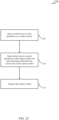
- FIG. 12 illustrates an example method 1200 for joint channel and phase noise estimation in accordance with various aspects of the present disclosure.
- the operations of method 1200 may be implemented by a BS 105, a UE 115, or their components as described with reference to FIGs. 1-11 .
- the operations of method 1200 may be performed by the BS control symbol component 140 as described with reference to FIGs. 1 , and 6-9 .
- the BS 105 may execute a set of codes to control the functional elements of the BS 105 to perform the functions described below. Additionally or alternatively, the BS 105 may perform aspects the functions described below using special-purpose hardware.
- the BS 105 may insert a control tone at a first periodicity in a first subcarrier of a control symbol as described with reference to FIGs. 2-5 .
- the operations of block 1205 may be performed by the BS control tone module 705 as described with reference to FIG. 7 .
- the BS 105 may insert a pilot tone at a second periodicity in a second subcarrier of the control symbol, the pilot tone being offset from the control tone in the control symbol as described with reference to FIGs. 2-5 .
- the operations of block 1410 may be performed by the BS pilot tone module 710 as described with reference to FIG. 7 .
- the BS 105 may transmit the control symbol as described with reference to FIGs. 2-5 .
- the operations of block 1215 may be performed by the BS transmitter 620 as described with reference to FIGs. 6-8 .
- FIG. 13 illustrates an example method 1300 for joint channel and phase noise estimation in accordance with various aspects of the present disclosure.
- the operations of method 1300 may be implemented by a UE 115 or its components as described with reference to FIGs. 1-11 .
- the operations of method 1300 may be performed by the UE control symbol component 145 as described with reference to FIGs. 1 and 9-11 .
- a UE 115 may execute a set of codes to control the functional elements of the UE 115 to perform the functions described below. Additionally or alternatively, the UE 115 may perform aspects the functions described below using special-purpose hardware.
- the method 1300 may also incorporate aspects of method 1200 of FIG. 12 .
- the UE 115 may receive a control symbol comprising a control tone at a first periodicity, and a pilot tone at a second periodicity, the pilot tone being offset from the control tone in the control symbol.
- the operations of block 1505 may be performed by the UE receiver 910 as described with reference to FIG. 9 .
- the UE 115 may perform performing a phase noise estimation and a channel estimation from the pilot tone as described with reference to FIGs. 2-5 .
- the operations of block 1310 may be performed by the estimation component 1015 as described with reference to FIG. 10 .
- methods 1200 and 1300 may provide for joint channel and phase noise estimation. It should be noted that methods 1200 and 1300 describe possible implementation, and that the operations and the steps may be rearranged or otherwise modified such that other implementations are possible. In some examples, aspects from two or more of the methods 1200 and 1300 may be combined.
- a CDMA system may implement a radio technology such as CDMA2000, Universal Terrestrial Radio Access (UTRA), etc.
- CDMA2000 covers IS-2000, IS-95, and IS-856 standards.
- IS-2000 Releases 0 and A are commonly referred to as CDMA2000 1X, 1X, etc.
- IS-856 (TIA-856) is commonly referred to as CDMA2000 1xEV-DO, High Rate Packet Data (HRPD), etc.
- UTRA includes Wideband CDMA (WCDMA) and other variants of CDMA.
- a TDMA system may implement a radio technology such as Global System for Mobile Communications (GSM).
- GSM Global System for Mobile Communications
- An OFDMA system may implement a radio technology such as Ultra Mobile Broadband (UMB), Evolved UTRA (E-UTRA), IEEE 802.11 (WiFi), IEEE 802.16 (WiMAX), IEEE 802.20, Flash-OFDM TM , etc.
- UMB Ultra Mobile Broadband
- E-UTRA Evolved UTRA
- WiFi WiFi
- WiMAX IEEE 802.16
- IEEE 802.20 Flash-OFDM TM
- UMB Ultra Mobile Broadband
- E-UTRA Evolved UTRA
- WiFi WiFi
- WiMAX IEEE 802.16
- IEEE 802.20 Flash-OFDM TM
- Flash-OFDM TM Flash-OFDM TM
- UMB Ultra Mobile Broadband
- E-UTRA Evolved UTRA
- WiFi WiFi
- WiMAX IEEE 802.16
- CDMA2000 and UMB are described in documents from an organization named "3rd Generation Partnership Project 2" (3GPP2).
- 3GPP2 3rd Generation Partnership Project 2
- the techniques described herein may be used for the systems and radio technologies mentioned above as well as other systems and radio technologies, including cellular (e.g., LTE) communications over an unlicensed and/or shared bandwidth.
- LTE Long Term Evolution
- LTE terminology is used in much of the description above, although the techniques are applicable beyond LTE/LTE-A applications.
- Information and signals may be represented using any of a variety of different technologies and techniques.
- data, instructions, commands, information, signals, bits, symbols, and chips that may be referenced throughout the above description may be represented by voltages, currents, electromagnetic waves, magnetic fields or particles, optical fields or particles, or any combination thereof.
- a general-purpose processor may be a microprocessor, but in the alternative, the processor may be any conventional processor, controller, microcontroller, or state machine.
- a processor may also be implemented as a combination of computing devices, e.g., a combination of a DSP and a microprocessor, multiple microprocessors, one or more microprocessors in conjunction with a DSP core, or any other such configuration.
- the functions described herein may be implemented in hardware, software executed by a processor, firmware, or any combination thereof. If implemented in software executed by a processor, the functions may be stored on or transmitted over as one or more instructions or code on a computer-readable medium. Other examples and implementations are within the scope of the disclosure and appended claims. For example, due to the nature of software, functions described above can be implemented using software executed by a processor, hardware, firmware, hardwiring, or combinations of any of these. Features implementing functions may also be physically located at various positions, including being distributed such that portions of functions are implemented at different physical locations.
- the term "and/or,” when used in a list of two or more items, means that any one of the listed items can be employed by itself, or any combination of two or more of the listed items can be employed.
- the composition can contain A alone; B alone; C alone; A and B in combination; A and C in combination; B and C in combination; or A, B, and C in combination.
- Computer-readable media includes both computer storage media and communication media including any medium that facilitates transfer of a computer program from one place to another.
- a storage medium may be any available medium that can be accessed by a general purpose or special purpose computer.
- computer-readable media can comprise RAM, ROM, EEPROM, flash memory, CD-ROM or other optical disk storage, magnetic disk storage or other magnetic storage devices, or any other medium that can be used to carry or store desired program code means in the form of instructions or data structures and that can be accessed by a general-purpose or special-purpose computer, or a general-purpose or special-purpose processor.
- any connection is properly termed a computer-readable medium.
- Disk and disc include compact disc (CD), laser disc, optical disc, digital versatile disc (DVD), floppy disk and Blu-ray disc where disks usually reproduce data magnetically, while discs reproduce data optically with lasers. Combinations of the above are also included within the scope of computer-readable media.
Landscapes
- Engineering & Computer Science (AREA)
- Signal Processing (AREA)
- Computer Networks & Wireless Communication (AREA)
- Power Engineering (AREA)
- Physics & Mathematics (AREA)
- Discrete Mathematics (AREA)
- General Physics & Mathematics (AREA)
- Mathematical Physics (AREA)
- Mobile Radio Communication Systems (AREA)
- Noise Elimination (AREA)
Applications Claiming Priority (3)
| Application Number | Priority Date | Filing Date | Title |
|---|---|---|---|
| US201562187773P | 2015-07-01 | 2015-07-01 | |
| US14/959,671 US10097255B2 (en) | 2015-07-01 | 2015-12-04 | Joint channel and phase noise estimation in control symbols of a millimeter wave link |
| PCT/US2016/035771 WO2017003642A1 (en) | 2015-07-01 | 2016-06-03 | Joint channel and phase noise estimation in control symbols of a millimeter wave link |
Publications (3)
| Publication Number | Publication Date |
|---|---|
| EP3318029A1 EP3318029A1 (en) | 2018-05-09 |
| EP3318029C0 EP3318029C0 (en) | 2025-01-08 |
| EP3318029B1 true EP3318029B1 (en) | 2025-01-08 |
Family
ID=56148677
Family Applications (1)
| Application Number | Title | Priority Date | Filing Date |
|---|---|---|---|
| EP16730948.3A Active EP3318029B1 (en) | 2015-07-01 | 2016-06-03 | Joint channel and phase noise estimation in control symbols of a millimeter wave link |
Country Status (8)
Families Citing this family (14)
| Publication number | Priority date | Publication date | Assignee | Title |
|---|---|---|---|---|
| US10219270B2 (en) * | 2015-09-04 | 2019-02-26 | Qualcomm Incorporated | Enabling operation of variable bandwidth users in millimeter-wave systems |
| US11146429B2 (en) | 2016-03-23 | 2021-10-12 | Nokia Technologies Oy | Common phase error and/or inter-carrier interference |
| US10439663B2 (en) * | 2016-04-06 | 2019-10-08 | Qualcomm Incorporated | Methods and apparatus for phase noise estimation in data symbols for millimeter wave communications |
| US10367672B2 (en) | 2016-09-28 | 2019-07-30 | Qualcomm Incorporated | Enhancements to phase-noise compensation reference signal design and scrambling |
| US10736082B2 (en) | 2016-10-31 | 2020-08-04 | Qualcomm Incorporated | Transmission of a common control in a beamforming system |
| CN106841770B (zh) * | 2017-01-24 | 2019-03-05 | 东南大学 | Si基微机械悬臂梁耦合间接加热式毫米波信号检测器 |
| US10382230B2 (en) | 2017-03-31 | 2019-08-13 | Mitsubishi Electric Research Laboratories, Inc. | System and method for channel estimation in mmWave communications exploiting joint AoD-AoA angular spread |
| CN109257080B (zh) * | 2018-09-07 | 2021-03-16 | 电子科技大学 | 大规模mimo系统下行链路中的多用户相位噪声补偿抑制方法 |
| CN109167744B (zh) * | 2018-11-06 | 2021-05-14 | 上海事凡物联网科技有限公司 | 一种相位噪声联合估计方法 |
| EP3723332A1 (en) * | 2019-04-08 | 2020-10-14 | Mitsubishi Electric R&D Centre Europe B.V. | Circular pilot sequences for joint channel and phase noise estimation |
| US11271690B2 (en) * | 2020-02-27 | 2022-03-08 | Qualcomm Incorporated | Techniques for phase tracking to enable higher modulation orders in wireless communications |
| US11349688B2 (en) * | 2020-09-28 | 2022-05-31 | Qualcomm Incorporated | Transmission rate control based on empirical MI estimation |
| US12143258B2 (en) * | 2021-10-20 | 2024-11-12 | Qualcomm Incorporated | Iterative phase-noise cancellation |
| WO2024183002A1 (en) * | 2023-03-07 | 2024-09-12 | Mediatek Singapore Pte. Ltd. | Reference signal design and processing for wireless sensing in integrated sensing and communications system |
Citations (1)
| Publication number | Priority date | Publication date | Assignee | Title |
|---|---|---|---|---|
| US20150029962A1 (en) * | 2013-07-26 | 2015-01-29 | Samsung Electronics Co., Ltd. | Transmitting apparatus, receiving apparatus, and controlling method thereof |
Family Cites Families (42)
| Publication number | Priority date | Publication date | Assignee | Title |
|---|---|---|---|---|
| JP4488605B2 (ja) * | 1999-07-30 | 2010-06-23 | パナソニック株式会社 | Ofdm信号の伝送方法、送信装置及び受信装置 |
| AU2003252639A1 (en) * | 2002-07-16 | 2004-02-02 | Matsushita Electric Industrial Co., Ltd. | Communicating method, transmitting device using the same, and receiving device using the same |
| US7203261B2 (en) * | 2003-04-07 | 2007-04-10 | Qualcomm Incorporated | Phase locked loop for an OFDM system |
| EP1657854A1 (en) * | 2003-08-19 | 2006-05-17 | Keio University | Radio communication device, ad hoc system, and communication system |
| US7453946B2 (en) * | 2003-09-03 | 2008-11-18 | Intel Corporation | Communication system and method for channel estimation and beamforming using a multi-element array antenna |
| US7372913B2 (en) * | 2004-07-22 | 2008-05-13 | Qualcomm Incorporated | Pilot tones in a multi-transmit OFDM system usable to capture transmitter diversity benefits |
| KR100927292B1 (ko) | 2005-02-03 | 2009-11-18 | 후지쯔 가부시끼가이샤 | 무선 통신 시스템 및 무선 통신 방법 |
| JP4526977B2 (ja) | 2005-03-02 | 2010-08-18 | 株式会社エヌ・ティ・ティ・ドコモ | 送信機および送信制御方法 |
| US7756548B2 (en) * | 2005-09-19 | 2010-07-13 | Qualcomm Incorporated | Methods and apparatus for use in a wireless communications system that uses a multi-mode base station |
| KR100863791B1 (ko) * | 2005-10-12 | 2008-10-17 | 삼성전자주식회사 | 주파수분할 다중접속 방식의 통신시스템에서 패킷 데이터 제어 채널을 이용하여 채널을 추정하기 위한 송수신 장치 및 방법과 그 시스템 |
| US8429502B2 (en) | 2005-11-16 | 2013-04-23 | Qualcomm Incorporated | Frame format for millimeter-wave systems |
| US7603093B2 (en) | 2005-12-14 | 2009-10-13 | Adc Telecommunications, Inc. | System and method to monitor broadband radio frequency transport systems |
| US20070165728A1 (en) * | 2006-01-17 | 2007-07-19 | Vladimir Parizhsky | Multi-symbol signals including an initial symbol and an extension portion |
| US20070237068A1 (en) * | 2006-04-06 | 2007-10-11 | Qi Bi | Method of providing pilot signals for uplink power control |
| CN101141428B (zh) * | 2006-09-06 | 2011-05-04 | 上海贝尔阿尔卡特股份有限公司 | 正交频分复用系统中的导频编译码方法及装置 |
| JP4995916B2 (ja) * | 2006-10-04 | 2012-08-08 | クゥアルコム・インコーポレイテッド | 無線通信システムにおけるsdmaのためのアップリンクack伝送 |
| WO2008132865A1 (ja) * | 2007-04-20 | 2008-11-06 | Sharp Kabushiki Kaisha | 基地局装置、端末装置、通信システム及び通信方法 |
| US8750917B2 (en) * | 2007-05-18 | 2014-06-10 | Qualcomm Incorporated | Multiplexing and power control of uplink control channels in a wireless communication system |
| EP2187551A1 (en) * | 2007-08-07 | 2010-05-19 | Sharp Kabushiki Kaisha | Base station device, terminal, and communication system |
| US8488693B2 (en) * | 2008-06-11 | 2013-07-16 | Industrial Technology Research Institute | Wireless communication systems and methods using reference signals |
| CN101604989B (zh) * | 2008-06-12 | 2013-04-24 | 北京信威通信技术股份有限公司 | 一种无线通信系统中调整传输功率的方法及装置 |
| DE102008032913A1 (de) * | 2008-07-12 | 2010-03-25 | Deutsches Zentrum für Luft- und Raumfahrt e.V. | Verfahren zur Kompensation von durch Ausblendung pulsförmiger Störeinflüsse erzeugten Informationsverlusten in einem Kommunikationssignal |
| US9277487B2 (en) * | 2008-08-01 | 2016-03-01 | Qualcomm Incorporated | Cell detection with interference cancellation |
| GB0818989D0 (en) * | 2008-10-16 | 2008-11-26 | Univ Glasgow | A telecommunications method and system |
| US8270517B2 (en) * | 2009-02-13 | 2012-09-18 | Qualcomm Incorporated | Method and apparatus for orthogonal pilot tone mapping in multiple-in and multiple-out (MIMO) and spatial division multiple access (SDMA) systems |
| EP2415190A4 (en) * | 2009-04-01 | 2015-07-29 | Lenovo Innovations Ltd Hong Kong | CHANNEL PROVISION FOR A CONTROL CHANNEL IN AN OFDM SYSTEM |
| JP2010278722A (ja) | 2009-05-28 | 2010-12-09 | Sharp Corp | 受信装置、受信方法、通信システムおよび通信方法 |
| US8437332B2 (en) * | 2009-06-22 | 2013-05-07 | Qualcomm Incorporated | Low complexity unified control channel processing |
| US8885541B2 (en) * | 2009-08-04 | 2014-11-11 | Qualcomm Incorporated | Extension of UE-RS to DWPTS |
| US9137076B2 (en) * | 2009-10-30 | 2015-09-15 | Qualcomm Incorporated | Method and apparatus for mutiplexing reference signal and data in a wireless communication system |
| US9264184B2 (en) * | 2009-10-30 | 2016-02-16 | Sony Corporation | Coordinated signaling of scheduling information for uplink and downlink communications |
| JP2012085084A (ja) * | 2010-10-12 | 2012-04-26 | Hitachi Kokusai Electric Inc | Ofdm信号送信装置 |
| US9084191B2 (en) * | 2011-01-20 | 2015-07-14 | Qualcomm Incorporated | Method and apparatus for determining timing information for cells |
| US8665811B2 (en) * | 2011-08-15 | 2014-03-04 | Motorola Mobility Llc | Reference signal for a control channel in wireless communication network |
| WO2013147764A1 (en) * | 2012-03-28 | 2013-10-03 | Intel Corporation | Device, system and method of communicating a wireless communication orthogonal-frequency-division-multiplexing signal |
| GB2500679A (en) * | 2012-03-29 | 2013-10-02 | Renesas Mobile Corp | Multicarrier channel with DFT based OFDM control/pilot signals and FB based OFDM user/payload signals |
| US9001812B2 (en) * | 2012-12-19 | 2015-04-07 | Nokia Solutions And Networks Oy | Timing error estimate of UL synchronization |
| US20140255029A1 (en) | 2013-03-05 | 2014-09-11 | Qualcomm Incorporated | Orthogonal frequency-division multiplexing burst markers |
| EP2987385A2 (en) * | 2013-04-15 | 2016-02-24 | Interdigital Patent Holdings, Inc. | Discontinuous reception (drx) schemes for millimeter wavelength (mmw) dual connectivity |
| US9374259B2 (en) * | 2013-09-30 | 2016-06-21 | Apple Inc. | Physical downlink control channel decoding |
| US9444595B2 (en) * | 2014-04-01 | 2016-09-13 | Qualcomm Incorporated | Hybrid waveform design combining OFDM and cyclic prefix based single carrier for millimeter-wave wireless communication |
| US9866299B2 (en) * | 2014-09-24 | 2018-01-09 | Mediatek Inc. | Synchronization in a beamforming system |
-
2015
- 2015-12-04 US US14/959,671 patent/US10097255B2/en active Active
-
2016
- 2016-06-03 CN CN201680038325.6A patent/CN107710703B/zh active Active
- 2016-06-03 JP JP2017567158A patent/JP6924707B2/ja active Active
- 2016-06-03 EP EP16730948.3A patent/EP3318029B1/en active Active
- 2016-06-03 WO PCT/US2016/035771 patent/WO2017003642A1/en unknown
- 2016-06-03 KR KR1020177037735A patent/KR102465717B1/ko active Active
- 2016-06-03 TW TW105117609A patent/TWI713532B/zh active
- 2016-06-03 AU AU2016286263A patent/AU2016286263B2/en active Active
Patent Citations (1)
| Publication number | Priority date | Publication date | Assignee | Title |
|---|---|---|---|---|
| US20150029962A1 (en) * | 2013-07-26 | 2015-01-29 | Samsung Electronics Co., Ltd. | Transmitting apparatus, receiving apparatus, and controlling method thereof |
Also Published As
| Publication number | Publication date |
|---|---|
| AU2016286263B2 (en) | 2020-01-30 |
| JP2018525875A (ja) | 2018-09-06 |
| US10097255B2 (en) | 2018-10-09 |
| AU2016286263A1 (en) | 2017-12-07 |
| KR20180026403A (ko) | 2018-03-12 |
| CN107710703B (zh) | 2020-11-10 |
| US20170005715A1 (en) | 2017-01-05 |
| EP3318029A1 (en) | 2018-05-09 |
| CN107710703A (zh) | 2018-02-16 |
| EP3318029C0 (en) | 2025-01-08 |
| TW201703444A (zh) | 2017-01-16 |
| TWI713532B (zh) | 2020-12-21 |
| KR102465717B1 (ko) | 2022-11-09 |
| WO2017003642A1 (en) | 2017-01-05 |
| BR112017028551A2 (pt) | 2018-09-04 |
| JP6924707B2 (ja) | 2021-08-25 |
Similar Documents
| Publication | Publication Date | Title |
|---|---|---|
| EP3318029B1 (en) | Joint channel and phase noise estimation in control symbols of a millimeter wave link | |
| EP3175573B1 (en) | Transmission of uplink control channels over an unlicensed radio frequency spectrum band | |
| CN110958080B (zh) | 针对增强型分量载波的信道状态信息过程 | |
| EP3335323B1 (en) | Phase noise estimation with dynamic pilot and zero tones pattern selection | |
| CA2957991C (en) | Flexible transmissions on one or more frequency division duplexing resources | |
| US10326546B2 (en) | Directional synchronization signals in wireless communications | |
| US9496975B2 (en) | Dynamic directional synchronization signals in wireless communications | |
| EP3372047B1 (en) | Techniques for managing cell identifiers and other parameters for flexible duplex operations | |
| US10171155B2 (en) | PUCCH transmit diversity with one-symbol STBC | |
| EP3357182B1 (en) | Clear channel assessment in lte controlled wi-fi | |
| US10085276B2 (en) | Frame configuration of dynamic uplink/downlink switch | |
| BR112017028551B1 (pt) | Estimativa de ruído de fase e de canal conjunta em símbolos de controle de um link de onda milimétrica |
Legal Events
| Date | Code | Title | Description |
|---|---|---|---|
| STAA | Information on the status of an ep patent application or granted ep patent |
Free format text: STATUS: THE INTERNATIONAL PUBLICATION HAS BEEN MADE |
|
| PUAI | Public reference made under article 153(3) epc to a published international application that has entered the european phase |
Free format text: ORIGINAL CODE: 0009012 |
|
| STAA | Information on the status of an ep patent application or granted ep patent |
Free format text: STATUS: REQUEST FOR EXAMINATION WAS MADE |
|
| 17P | Request for examination filed |
Effective date: 20171115 |
|
| AK | Designated contracting states |
Kind code of ref document: A1 Designated state(s): AL AT BE BG CH CY CZ DE DK EE ES FI FR GB GR HR HU IE IS IT LI LT LU LV MC MK MT NL NO PL PT RO RS SE SI SK SM TR |
|
| AX | Request for extension of the european patent |
Extension state: BA ME |
|
| DAV | Request for validation of the european patent (deleted) | ||
| DAX | Request for extension of the european patent (deleted) | ||
| STAA | Information on the status of an ep patent application or granted ep patent |
Free format text: STATUS: EXAMINATION IS IN PROGRESS |
|
| 17Q | First examination report despatched |
Effective date: 20200217 |
|
| STAA | Information on the status of an ep patent application or granted ep patent |
Free format text: STATUS: EXAMINATION IS IN PROGRESS |
|
| GRAP | Despatch of communication of intention to grant a patent |
Free format text: ORIGINAL CODE: EPIDOSNIGR1 |
|
| STAA | Information on the status of an ep patent application or granted ep patent |
Free format text: STATUS: GRANT OF PATENT IS INTENDED |
|
| INTG | Intention to grant announced |
Effective date: 20240814 |
|
| GRAS | Grant fee paid |
Free format text: ORIGINAL CODE: EPIDOSNIGR3 |
|
| GRAA | (expected) grant |
Free format text: ORIGINAL CODE: 0009210 |
|
| STAA | Information on the status of an ep patent application or granted ep patent |
Free format text: STATUS: THE PATENT HAS BEEN GRANTED |
|
| AK | Designated contracting states |
Kind code of ref document: B1 Designated state(s): AL AT BE BG CH CY CZ DE DK EE ES FI FR GB GR HR HU IE IS IT LI LT LU LV MC MK MT NL NO PL PT RO RS SE SI SK SM TR |
|
| REG | Reference to a national code |
Ref country code: GB Ref legal event code: FG4D |
|
| REG | Reference to a national code |
Ref country code: CH Ref legal event code: EP |
|
| REG | Reference to a national code |
Ref country code: DE Ref legal event code: R096 Ref document number: 602016090890 Country of ref document: DE |
|
| REG | Reference to a national code |
Ref country code: IE Ref legal event code: FG4D |
|
| U01 | Request for unitary effect filed |
Effective date: 20250116 |
|
| U07 | Unitary effect registered |
Designated state(s): AT BE BG DE DK EE FI FR IT LT LU LV MT NL PT RO SE SI Effective date: 20250122 |
|
| U20 | Renewal fee for the european patent with unitary effect paid |
Year of fee payment: 10 Effective date: 20250512 |
|
| PG25 | Lapsed in a contracting state [announced via postgrant information from national office to epo] |
Ref country code: RS Free format text: LAPSE BECAUSE OF FAILURE TO SUBMIT A TRANSLATION OF THE DESCRIPTION OR TO PAY THE FEE WITHIN THE PRESCRIBED TIME-LIMIT Effective date: 20250408 |
|
| PG25 | Lapsed in a contracting state [announced via postgrant information from national office to epo] |
Ref country code: PL Free format text: LAPSE BECAUSE OF FAILURE TO SUBMIT A TRANSLATION OF THE DESCRIPTION OR TO PAY THE FEE WITHIN THE PRESCRIBED TIME-LIMIT Effective date: 20250108 |
|
| PG25 | Lapsed in a contracting state [announced via postgrant information from national office to epo] |
Ref country code: ES Free format text: LAPSE BECAUSE OF FAILURE TO SUBMIT A TRANSLATION OF THE DESCRIPTION OR TO PAY THE FEE WITHIN THE PRESCRIBED TIME-LIMIT Effective date: 20250108 |
|
| PGFP | Annual fee paid to national office [announced via postgrant information from national office to epo] |
Ref country code: GB Payment date: 20250508 Year of fee payment: 10 |
|
| PG25 | Lapsed in a contracting state [announced via postgrant information from national office to epo] |
Ref country code: NO Free format text: LAPSE BECAUSE OF FAILURE TO SUBMIT A TRANSLATION OF THE DESCRIPTION OR TO PAY THE FEE WITHIN THE PRESCRIBED TIME-LIMIT Effective date: 20250408 Ref country code: IS Free format text: LAPSE BECAUSE OF FAILURE TO SUBMIT A TRANSLATION OF THE DESCRIPTION OR TO PAY THE FEE WITHIN THE PRESCRIBED TIME-LIMIT Effective date: 20250508 |
|
| PG25 | Lapsed in a contracting state [announced via postgrant information from national office to epo] |
Ref country code: HR Free format text: LAPSE BECAUSE OF FAILURE TO SUBMIT A TRANSLATION OF THE DESCRIPTION OR TO PAY THE FEE WITHIN THE PRESCRIBED TIME-LIMIT Effective date: 20250108 |
|
| PG25 | Lapsed in a contracting state [announced via postgrant information from national office to epo] |
Ref country code: GR Free format text: LAPSE BECAUSE OF FAILURE TO SUBMIT A TRANSLATION OF THE DESCRIPTION OR TO PAY THE FEE WITHIN THE PRESCRIBED TIME-LIMIT Effective date: 20250409 |
|
| PGFP | Annual fee paid to national office [announced via postgrant information from national office to epo] |
Ref country code: IE Payment date: 20250514 Year of fee payment: 10 |