EP3317658B1 - Turbidity sensor based on ultrasound measurements - Google Patents
Turbidity sensor based on ultrasound measurements Download PDFInfo
- Publication number
- EP3317658B1 EP3317658B1 EP16736786.1A EP16736786A EP3317658B1 EP 3317658 B1 EP3317658 B1 EP 3317658B1 EP 16736786 A EP16736786 A EP 16736786A EP 3317658 B1 EP3317658 B1 EP 3317658B1
- Authority
- EP
- European Patent Office
- Prior art keywords
- turbidity
- transducer
- fluid
- ultrasonic
- frequency
- Prior art date
- Legal status (The legal status is an assumption and is not a legal conclusion. Google has not performed a legal analysis and makes no representation as to the accuracy of the status listed.)
- Active
Links
Images


Classifications
-
- G—PHYSICS
- G01—MEASURING; TESTING
- G01N—INVESTIGATING OR ANALYSING MATERIALS BY DETERMINING THEIR CHEMICAL OR PHYSICAL PROPERTIES
- G01N29/00—Investigating or analysing materials by the use of ultrasonic, sonic or infrasonic waves; Visualisation of the interior of objects by transmitting ultrasonic or sonic waves through the object
- G01N29/02—Analysing fluids
- G01N29/032—Analysing fluids by measuring attenuation of acoustic waves
-
- G—PHYSICS
- G01—MEASURING; TESTING
- G01D—MEASURING NOT SPECIALLY ADAPTED FOR A SPECIFIC VARIABLE; ARRANGEMENTS FOR MEASURING TWO OR MORE VARIABLES NOT COVERED IN A SINGLE OTHER SUBCLASS; TARIFF METERING APPARATUS; MEASURING OR TESTING NOT OTHERWISE PROVIDED FOR
- G01D4/00—Tariff metering apparatus
- G01D4/002—Remote reading of utility meters
- G01D4/004—Remote reading of utility meters to a fixed location
-
- G—PHYSICS
- G01—MEASURING; TESTING
- G01F—MEASURING VOLUME, VOLUME FLOW, MASS FLOW OR LIQUID LEVEL; METERING BY VOLUME
- G01F1/00—Measuring the volume flow or mass flow of fluid or fluent solid material wherein the fluid passes through a meter in a continuous flow
- G01F1/66—Measuring the volume flow or mass flow of fluid or fluent solid material wherein the fluid passes through a meter in a continuous flow by measuring frequency, phase shift or propagation time of electromagnetic or other waves, e.g. using ultrasonic flowmeters
- G01F1/666—Measuring the volume flow or mass flow of fluid or fluent solid material wherein the fluid passes through a meter in a continuous flow by measuring frequency, phase shift or propagation time of electromagnetic or other waves, e.g. using ultrasonic flowmeters by detecting noise and sounds generated by the flowing fluid
-
- G—PHYSICS
- G01—MEASURING; TESTING
- G01M—TESTING STATIC OR DYNAMIC BALANCE OF MACHINES OR STRUCTURES; TESTING OF STRUCTURES OR APPARATUS, NOT OTHERWISE PROVIDED FOR
- G01M3/00—Investigating fluid-tightness of structures
- G01M3/02—Investigating fluid-tightness of structures by using fluid or vacuum
- G01M3/04—Investigating fluid-tightness of structures by using fluid or vacuum by detecting the presence of fluid at the leakage point
- G01M3/24—Investigating fluid-tightness of structures by using fluid or vacuum by detecting the presence of fluid at the leakage point using infrasonic, sonic, or ultrasonic vibrations
- G01M3/243—Investigating fluid-tightness of structures by using fluid or vacuum by detecting the presence of fluid at the leakage point using infrasonic, sonic, or ultrasonic vibrations for pipes
-
- G—PHYSICS
- G01—MEASURING; TESTING
- G01M—TESTING STATIC OR DYNAMIC BALANCE OF MACHINES OR STRUCTURES; TESTING OF STRUCTURES OR APPARATUS, NOT OTHERWISE PROVIDED FOR
- G01M3/00—Investigating fluid-tightness of structures
- G01M3/02—Investigating fluid-tightness of structures by using fluid or vacuum
- G01M3/26—Investigating fluid-tightness of structures by using fluid or vacuum by measuring rate of loss or gain of fluid, e.g. by pressure-responsive devices, by flow detectors
- G01M3/28—Investigating fluid-tightness of structures by using fluid or vacuum by measuring rate of loss or gain of fluid, e.g. by pressure-responsive devices, by flow detectors for pipes, cables or tubes; for pipe joints or seals; for valves ; for welds
- G01M3/2807—Investigating fluid-tightness of structures by using fluid or vacuum by measuring rate of loss or gain of fluid, e.g. by pressure-responsive devices, by flow detectors for pipes, cables or tubes; for pipe joints or seals; for valves ; for welds for pipes
- G01M3/2815—Investigating fluid-tightness of structures by using fluid or vacuum by measuring rate of loss or gain of fluid, e.g. by pressure-responsive devices, by flow detectors for pipes, cables or tubes; for pipe joints or seals; for valves ; for welds for pipes using pressure measurements
-
- G—PHYSICS
- G01—MEASURING; TESTING
- G01N—INVESTIGATING OR ANALYSING MATERIALS BY DETERMINING THEIR CHEMICAL OR PHYSICAL PROPERTIES
- G01N29/00—Investigating or analysing materials by the use of ultrasonic, sonic or infrasonic waves; Visualisation of the interior of objects by transmitting ultrasonic or sonic waves through the object
- G01N29/22—Details, e.g. general constructional or apparatus details
- G01N29/222—Constructional or flow details for analysing fluids
-
- G—PHYSICS
- G01—MEASURING; TESTING
- G01N—INVESTIGATING OR ANALYSING MATERIALS BY DETERMINING THEIR CHEMICAL OR PHYSICAL PROPERTIES
- G01N29/00—Investigating or analysing materials by the use of ultrasonic, sonic or infrasonic waves; Visualisation of the interior of objects by transmitting ultrasonic or sonic waves through the object
- G01N29/44—Processing the detected response signal, e.g. electronic circuits specially adapted therefor
- G01N29/50—Processing the detected response signal, e.g. electronic circuits specially adapted therefor using auto-correlation techniques or cross-correlation techniques
-
- G—PHYSICS
- G01—MEASURING; TESTING
- G01N—INVESTIGATING OR ANALYSING MATERIALS BY DETERMINING THEIR CHEMICAL OR PHYSICAL PROPERTIES
- G01N2291/00—Indexing codes associated with group G01N29/00
- G01N2291/01—Indexing codes associated with the measuring variable
- G01N2291/015—Attenuation, scattering
-
- G—PHYSICS
- G01—MEASURING; TESTING
- G01N—INVESTIGATING OR ANALYSING MATERIALS BY DETERMINING THEIR CHEMICAL OR PHYSICAL PROPERTIES
- G01N2291/00—Indexing codes associated with group G01N29/00
- G01N2291/02—Indexing codes associated with the analysed material
- G01N2291/024—Mixtures
- G01N2291/02408—Solids in gases, e.g. particle suspensions
-
- G—PHYSICS
- G01—MEASURING; TESTING
- G01N—INVESTIGATING OR ANALYSING MATERIALS BY DETERMINING THEIR CHEMICAL OR PHYSICAL PROPERTIES
- G01N2291/00—Indexing codes associated with group G01N29/00
- G01N2291/02—Indexing codes associated with the analysed material
- G01N2291/024—Mixtures
- G01N2291/02416—Solids in liquids
-
- G—PHYSICS
- G01—MEASURING; TESTING
- G01N—INVESTIGATING OR ANALYSING MATERIALS BY DETERMINING THEIR CHEMICAL OR PHYSICAL PROPERTIES
- G01N2291/00—Indexing codes associated with group G01N29/00
- G01N2291/02—Indexing codes associated with the analysed material
- G01N2291/028—Material parameters
- G01N2291/02836—Flow rate, liquid level
-
- G—PHYSICS
- G01—MEASURING; TESTING
- G01N—INVESTIGATING OR ANALYSING MATERIALS BY DETERMINING THEIR CHEMICAL OR PHYSICAL PROPERTIES
- G01N2291/00—Indexing codes associated with group G01N29/00
- G01N2291/02—Indexing codes associated with the analysed material
- G01N2291/028—Material parameters
- G01N2291/02872—Pressure
-
- G—PHYSICS
- G01—MEASURING; TESTING
- G01N—INVESTIGATING OR ANALYSING MATERIALS BY DETERMINING THEIR CHEMICAL OR PHYSICAL PROPERTIES
- G01N2291/00—Indexing codes associated with group G01N29/00
- G01N2291/04—Wave modes and trajectories
- G01N2291/044—Internal reflections (echoes), e.g. on walls or defects
-
- G—PHYSICS
- G01—MEASURING; TESTING
- G01N—INVESTIGATING OR ANALYSING MATERIALS BY DETERMINING THEIR CHEMICAL OR PHYSICAL PROPERTIES
- G01N2291/00—Indexing codes associated with group G01N29/00
- G01N2291/10—Number of transducers
- G01N2291/102—Number of transducers one emitter, one receiver
-
- Y—GENERAL TAGGING OF NEW TECHNOLOGICAL DEVELOPMENTS; GENERAL TAGGING OF CROSS-SECTIONAL TECHNOLOGIES SPANNING OVER SEVERAL SECTIONS OF THE IPC; TECHNICAL SUBJECTS COVERED BY FORMER USPC CROSS-REFERENCE ART COLLECTIONS [XRACs] AND DIGESTS
- Y02—TECHNOLOGIES OR APPLICATIONS FOR MITIGATION OR ADAPTATION AGAINST CLIMATE CHANGE
- Y02B—CLIMATE CHANGE MITIGATION TECHNOLOGIES RELATED TO BUILDINGS, e.g. HOUSING, HOUSE APPLIANCES OR RELATED END-USER APPLICATIONS
- Y02B90/00—Enabling technologies or technologies with a potential or indirect contribution to GHG emissions mitigation
- Y02B90/20—Smart grids as enabling technology in buildings sector
-
- Y—GENERAL TAGGING OF NEW TECHNOLOGICAL DEVELOPMENTS; GENERAL TAGGING OF CROSS-SECTIONAL TECHNOLOGIES SPANNING OVER SEVERAL SECTIONS OF THE IPC; TECHNICAL SUBJECTS COVERED BY FORMER USPC CROSS-REFERENCE ART COLLECTIONS [XRACs] AND DIGESTS
- Y04—INFORMATION OR COMMUNICATION TECHNOLOGIES HAVING AN IMPACT ON OTHER TECHNOLOGY AREAS
- Y04S—SYSTEMS INTEGRATING TECHNOLOGIES RELATED TO POWER NETWORK OPERATION, COMMUNICATION OR INFORMATION TECHNOLOGIES FOR IMPROVING THE ELECTRICAL POWER GENERATION, TRANSMISSION, DISTRIBUTION, MANAGEMENT OR USAGE, i.e. SMART GRIDS
- Y04S20/00—Management or operation of end-user stationary applications or the last stages of power distribution; Controlling, monitoring or operating thereof
- Y04S20/30—Smart metering, e.g. specially adapted for remote reading
Definitions
- the present invention relates to the field of turbidity sensors for measurement of turbidity of a fluid. Especially, the invention provides a device capable of measuring turbidity based on ultrasonic measurements. Further, the invention provides an ultrasonic consumption meter, or utility meter, comprising such turbidity sensor.
- a complete analysis of cleanness of water involves complicated biochemical analyses, however in some cases a measure of water quality obtained by means of a turbidity measurement can be sufficient, i.e. measurement of the amount of particles in the fluid as a measure of cleanness of the fluid.
- turbidity measurements can be based on optical methods.
- WO 2012/129170 discloses a device including two ultrasonic transducers for creating a standing wave in a flow pipe.
- the standing wave is used as an acoustic comb filter for capturing particles flowing in the flow pipe.
- the scientific article "Optical measurements of acoustic pressure amplitudes at the sensitivity of Reyleigh scattering" by Anne Rausch et al discloses how a speaker arranged in association with a fluid can be used to measure acoustic pressure amplitudes of particles in the fluid.
- WO 2013/059360 discloses an apparatus for determining particle sizes in a suspension based on particle velocity measured using ultrasound interrogation signals.
- Optical turbidity equipment is not well-suited for functioning as a permanently mounted part of a utility network due to the forming of coatings of minerals and/or biofilms on the optical surfaces, which will disturb the turbidity measurements and necessitate frequent maintenance. Furthermore, such optical turbidity measurement equipment is expensive and can thus in practice only be installed at a limited number of positions in a utility network.
- the invention provides a device arranged to measure turbidity of a fluid flowing in a flow tube, the device comprising:
- the invention is based on the insight that particles in a fluid will scatter ultrasonic waves in the surrounding fluid.
- the ultrasonic wave is generated in a flow tube between two boundaries, e.g. a wave based on applying to the first transducer an ultrasonic pure tone having a frequency f 0 .
- a particle moving along with fluid flowing in the flow tube will then pass the acoustic wave, and when passing a zone with high ultrasonic intensity, the particle will scatter ultrasonic waves with the frequency of the wave f 0 at a relatively high intensity.
- the particle will not scatter any ultrasonic waves when passing a zone with low ultrasonic intensity.
- the receiver after demodulating with frequency f 0 , the receiver will exhibit a residual oscillation at a frequency, f s , depending on the velocity, v, with which the particles have travelled along the wave.
- a high intensity of ultrasound is desired. This can be achieved by employing the flow tube as a resonator to the ultrasound, hence choosing an ultrasound frequency so that the wave after a round trip back and forth in the measurement section will be reflected in-phase with itself.
- the resulting intensity pattern will be a standing wave, having anti-nodes of high intensity and nodes of low intensity.
- the standing wave will turn into (a) unidirectional traveling wave(s). Even in this case, however, the device according to the invention will still be able to measure the turbidity since a particle moving with the flow scatters on the traveling wave.
- the frequency of the scattered ultrasound is downshifted in frequency if the flow and ultrasound propagation is in the same direction and upshifted in frequency if the flow and ultrasound propagation is opposite. This is known as the Doppler shift or Doppler effect.
- the receiver transducer will detect this frequency-shifted signal. This frequency shift is comparable to the standing wave signal, but will not benefit from the intensity enhancement of the resonator.
- the ultrasound scattered by impurities travelling with the fluid and detected at the receiver will exhibit the frequency f s after demodulation with the carrier frequency f 0 .
- the reason in this case is that the impurities are travelling with velocity v relative to the ultrasonic source and hence experience a Doppler shifted ultrasonic frequency, which is scattered into the receiver.
- Doppler turbidity sensors are known in the art. These employ only a single transducer acting simultaneously as transmitter and receiver. The demands to such a transducer are quite severe, since the oscillations from signal transmission must have died out at the time the echo reaches the transducer. Hence, the transducer must be efficiently mechanically damped, which in turn limits the coherence of the ultrasonic wave and hence the accuracy of the sensor. Utilizing several transducers as is proposed in the present invention, allows for optimizing these for their respective functions in the sensor and elimination of the above problem.
- the transmitter can be designed to oscillate at a high Q-value resonance resulting in high coherence, high intensity and high quality wave propagation pattern
- the dedicated receiver can be designed to have high bandwidth and high sensitivity resulting in high frequency resolution of the scattered ultrasonic waves.
- the first transducer may be arranged at said first section, creating a travelling wave propagating either parallel, antiparallel or at an oblique angle different from 90 degrees relative to the mean fluid velocity.
- the receiving transducer may be arranged perpendicular to the travelling wave propagation direction so that no reflections apart from the desired scattered signal are detected.
- the electronic signal derived from the receiving transducer is demodulated with the ultrasonic frequency f 0 and the resulting signal is spectrally analysed to yield a quantity indicative of the turbidity level as the spectral density in a frequency band around f s .
- the first and second transducers are operating in a transient mode, where they emit wavepackets shorter than the length of the measurement section.
- the measurement section cannot perform as a resonator but a transient standing wave pattern will still occur in the region of the measurement section, where the wavepackets collide.
- the demodulated signal from the receiver will still exhibit the frequency f s , but the technical complexity associated with tracking the resonance of the measurement section is reduced.
- Noise suppression and improvement of signal to noise ratio may be achieved by synchronizing the receiver with the wavepacket generation using standard lock-in techniques.
- the ultrasonic transducers may occasionally be operated in a fashion appropriate for a time-of-flight or Doppler flow meter. It is reasonable to assume that the particles move with the same velocity as the fluid, hence the flow measurement readily yields the value of v, using two transducers. Consequently, knowledge of the fluid velocity implies that the expected values of f s is known, meaning that an adaptive digital filter can be employed to select a band around this frequency thereby rejecting background noise. Such filtering techniques are well known in the art of digital signal processing.
- the ultrasonic flow meter operation mode of the turbidity sensor may accordingly also be utilised to provide a measurement of the fluid temperature as well. This becomes apparent, since the essence of the time-of-flight flow measurement is the timing of two ultrasonic wave packets travelling between two transducers co- and counter-propagating to the fluid flow respectively. The length of the measurement section divided by the average travelling time of the two wave packets results in the speed of sound in the fluid.
- a separate, dedicated temperature sensor may be included in the turbidity sensor in order to determine the temperature dependent value of c by means of a lookup table.
- c is temperature dependent. Although it is still possible to provide a measure of turbidity based on temperature estimates, a more reliable turbidity measurement may be obtained in those cases of in-situ measurements of the fluid temperature, e.g. by means of a temperature sensor integrated with the device.
- the power of ultrasonic waves scattered from a particle is proportional to the 4 th power of the ultrasonic wave frequency, and proportional to the 2 nd power of the volume of the particle.
- Quantifying the amount of such particles provides a measure of turbidity of a fluid, e.g. water in a drinking water utility network, which is a useful measure of general cleanness of the fluid.
- the technique may even have a sensitivity allowing for the detection of microbes, amoebae and bacteria in sufficiently high concentrations.
- a turbidity measurement device can easily be combined and integrated with existing ultrasonic flow meters, e.g. as known in ultrasonic consumption meters.
- the turbidity measurement facility can be provided by a single component without the need for installing a separate device to monitor turbidity of a fluid in a utility network.
- the wireless communication network of such consumption meters can be used for turbidity data as well, thereby allowing collection of turbidity data from the location of a large number of consumers, e.g. for further processing which can help to determine the location of a source of contamination in the piping network.
- first and the second 'section end' indicate ends of the turbidity measurement section, i.e. ends of the section wherein the ultrasonic wave extends along the fluid direction in the flow tube.
- control circuit' is understood the necessary electronic circuits adapted to control the function of the ultrasound transducer(s), i.e. to generate electric signals to drive the first transducer, and to receive electric signals from the receiver transducer.
- the first transducer may be arranged at said first section end, and wherein a reflecting element is arranged at the second section end, e.g. to constitute the second section end, for reflecting the ultrasonic signals.
- the first transducer may be arranged at a central part of the flow tube cross sectional area and facing an ultrasonic reflecting element also arranged at a central part of the flow tube cross sectional area, e.g. such as at a distance of 5-15 cm from the first transducer, thus allowing the ultrasonic wave become a standing wave between the first transducer and the reflecting element.
- the first transducer and the reflecting element preferably occupy only a limited fraction of the flow tube cross section area, so as to allow the fluid to flow around these parts without creating any significant disturbance or turbulence in the fluid.
- the device may comprise a second transducer arranged at the second section end, so as to provide a second ultrasonic wave between the second and first section ends, and wherein the control circuit is arranged for operating both of the first and second transducers.
- the control circuit is capable of driving the first and second transducers to generate said first and second ultrasonic waves simultaneously.
- the first and second ultrasonic waves may have similar frequencies, thus the control circuit may be arranged to apply electrical signals, e.g. pure tone signals, with the same frequency e.g. within 1-100 MHz, or more specifically within 2-20 MHz, such as 5-10 MHz.
- the same electrical signal may be applied to both of the first and second transducers.
- the first and second ultrasonic waves may have different frequencies.
- a frequency of the first ultrasonic wave may be a rational number p/q times the second frequency of the second wave. This may be advantageous, since in order to provide a high acoustic output, the transducers used may be driven near or at their mechanical resonance frequency, and thus using the same type of transducer for the first and second transducers, driving one transducer at an odd harmonic of its mechanical resonance frequency will still provide a high acoustic output. Further, a frequency of the first ultrasonic wave and a second frequency of the second ultrasonic wave may differ by 0.1% to 10%.
- the first and second waves are preferably spatially overlapping, e.g. with the first and second transducers arranged at the respective first and second section ends.
- the invention further provides an ultrasonic flow meter comprising first and second ultrasonic transducers arranged to generate respective first and second ultrasonic waves in a flow tube, wherein the a first frequency of the first ultrasonic wave is different from a second frequency of the second ultrasonic wave.
- the flow meter comprises a control circuit connected to operate the first and second transducers, and being arranged to generate an output indicative of a flow rate of the fluid in the flow tube, preferably in response to sensing an ultrasonic response from scattering on particles of the fluid flowing along the first and second ultrasonic waves.
- the control circuit may be arranged to generate the signal indicative of the turbidity of the fluid in response to signals received from the receiver transducer and a flow rate of the fluid.
- ⁇ is the angle between sound propagation direction and mean fluid velocity direction
- v is the velocity of the particles responsible for the turbidity
- c is the speed of the ultrasonic wave in the fluid.
- This is preferably utilized in the processing in the control circuit, e.g.
- control circuit may be arranged to generate the signal indicative of the turbidity of the fluid in response to an output from a predetermined algorithm in response to both of: a measured flow rate of the fluid in the flow tube, and a frequency of the ultrasonic standing wave.
- said predetermined algorithm may involve calculating a level of the ultrasonic signals received by the receiver transducer at one or more frequency components selected in response to both of: the measured flow rate of the fluid in the flow tube, and the frequency of the ultrasonic standing wave.
- the first ultrasonic wave is a standing wave.
- the first ultrasonic wave is a travelling wave.
- the first and the second ultrasonic waves are standing waves.
- the first and the second ultrasonic waves are travelling waves.
- standing waves provides areas of high acoustic intensity at the antinodes of the wave, and thus high scattering intensity.
- the application of travelling waves i.e. non-standing waves, provides higher freedom-of-design of the device.
- the first and second ultrasonic waves are transient waves of similar frequency in the form of wave packets, which are shorter than the distance between the first section end and the second section end, so as to form a transient standing wave in at least part of the turbidity measurement section.
- the device may comprise flow measurement means so as to provide a flow rate to be used by the control circuit to calculate a more reliable measure of turbidity, as explained above.
- the flow rate may be provided by an external device, or it may be measured by an integral flow meter of the device itself.
- the flow measurement means may comprise the first transducer, and preferably also a second transducer, and a control circuit operating the first and second transducers according to a time-of-flight or Doppler principle.
- a combined flow meter and turbidity meter can be provided utilizing the same ultrasound transducer and control circuit.
- control circuit may be arranged to operate the first transducer in a first and a second operation time intervals, wherein the first and second operation time intervals are not overlapping, wherein the control circuit is arranged to operate the first transducer for measuring the turbidity of the fluid flowing in the flow tube during the first operation time interval, and wherein the control circuit is arranged to operate the first transducer for measuring the flow rate of the fluid flowing in the flow tube during the second operation time interval.
- the control circuit may be arranged to operate the first transducer at a first frequency for measuring the turbidity, and being arranged to operate the first transducer at a second frequency for measuring the flow rate, such as the first frequency being higher than the second frequency, such as the first frequency being the odd harmonic, like the third harmonic of the first frequency.
- This frequency difference allows flow rate to be measured at a reasonably low frequency, while turbidity measurements can be provided at a higher frequency to increase sensitivity to detect small particles in the fluid.
- the first frequency may be above 1 MHz, such as above 10 MHz, and wherein the second frequency is below 5 MHz, such as below 2 MHz.
- the control circuit may be arranged to calculate a level of ultrasonic signals received by the receiver transducer, and to generate the signal indicative of the turbidity of the fluid accordingly, without any knowledge about fluid flow rate in the flow tube.
- the turbidity precision that can be obtained in this way may be sufficient, however a more complicated data processing may be required compared to methods utilizing fluid rate - either provided from an external device, or by the integration of the turbidity device with a flow meter, as already described.
- the control circuit may be arranged to generate the signal indicative of the turbidity of the fluid in response to an average of measured values over a period of time, hereby allowing only a limited amount of measured turbidity values to be communicated.
- the device may comprise temperature measurement means arranged to measure a temperature of the fluid.
- said temperature measurement means may comprise the first transducer, and preferably also a second transducer.
- the first transducers may be used for turbidity measurements, flow rate measurements, as well as temperature measurements.
- the device may comprise a first ultrasonic reflector arranged to guide ultrasonic signals from the first transducer in a direction opposite the flow direction in the turbidity measurement section.
- a second ultrasonic reflector may be arranged to guide ultrasonic signals from the second transducer in a direction of the fluid flowing.
- first and second ultrasonic reflectors may constitute the first and second end sections between which the ultrasonic wave extends.
- Such reflectors allow the first (and possibly second) transducer(s) to be arranged away from a central part of the fluid flow, e.g. with the(se) transducer(s) to be positioned at or near the wall of the flow tube.
- the device may comprise an acoustic lens or an aperture arranged in relation to the receiver transducer, so as to limit area volume of the turbidity measurement section from which ultrasonic signals can reach the receiver transducer and so discriminate against unwanted background from stray scattering of ultrasound.
- the receiver transducer may be arranged in an opening in a wall of the flow tube, such as the receiver transducer being arranged with its receiver surface retracted behind a surface covering said opening.
- the receiver transducer may be retracted in a well, thus serving to reduce unwanted ultrasonic reflections from the flow tube in reaching the receiver transducer, thereby increasing the turbidity measurement precision.
- the receiver transducer is preferably arranged between the first and second section ends, e.g. centrally between said section ends, such as with its receiver surface forming a plane containing the flow direction of the fluid flowing in the turbidity measurement section.
- Such arrangements of the receiver transducer allow for efficient reception of scattered signal at high signal-to-noise ratio.
- the receiver transducer may comprise a plurality of separate transducers arranged at respective positions along the turbidity measurement section. Such array of separate receiver transducers spatially distributed along the ultrasonic standing wave may provide an improved response signal for further processing compared to a single received transducer.
- the first transducer may comprise a piezoelectric transducer.
- the piezoelectric transducer may exhibit a mechanical resonance frequency coinciding with a frequency of a drive signal applied to the piezoelectric transducer by the control circuit. This allows the transducer to provide a high acoustic output, and thus provide an ultrasonic standing wave with a high intensity, thereby allowing scattered signals from particles in the fluid to allow a robust turbidity measurement.
- control circuit may be arranged to operate the first transducer at said mechanical resonance frequency for measurement of flow rate, and wherein the control circuit is arranged to operate the first transducer at a higher frequency for measurement of turbidity, and wherein said higher frequency is selected to coincide with an odd harmonic of said mechanical resonance frequency.
- the same transducer can be used to provide a high acoustic output at the two different frequencies for turbidity and flow measurements, respectively.
- the first transducer may be arranged in a central part of a cross section of the flow tube, and e.g. constitute the first section end.
- the receiver transducer may comprise a piezoelectric transducer.
- the device may comprise a liner formed by a material comprising a polymer for covering at least part of a surface of a measurement tube in the turbidity measurement section.
- the device may be integrated or combined with an ultrasonic flow meter which may be or may be part of a charging consumption meter or utility meter, e.g. a water meter for cold and/or hot water, a heat meter, a cooling meter, or a gas meter, where the consumption meter is arranged for measuring consumption data of a supplied utility used as a basis for billing.
- the consumption meter may be used in connection with district heating, district cooling and/or distributed water supply.
- the consumption meter may be a legal meter, i.e. a meter which is subdued to regulatory demands. Such regulatory demands may be demands to the precision of the measurements.
- the flow meter can be used as a water meter, thus allowing measurement of the amount of particles (i.e. turbidity) in the supplied water.
- the control circuit preferably comprises a measurement circuit to allow measurement of fluid flow according to known principles of ultrasonic transit time.
- the measurement circuit may be arranged on one single printed circuit board (PCB) capable of generating as output a pulse train indicative of the measured fluid flow rate.
- PCB printed circuit board
- One single processor may be used to handle measurement of both flow rate and turbidity, however separate processors may as well be provided for calculation of flow rate and turbidity.
- the device may comprise a communication module connected to the control circuit and arranged for communicating the signal indicative of the turbidity of the fluid, e.g. turbidity data may be communicated as a wireless radio frequency signal.
- a specific embodiment of the first aspect provides a device, wherein the first transducer is arranged at the first section end, and wherein a second transducer is arranged at the second section end, so as to provide a second ultrasonic standing wave between the second and first boundaries, and wherein the control circuit is arranged for operating both of the first and the second transducers, wherein the control circuit is arranged to generate the signal indicative of the turbidity of the fluid in response to signals received from the receiver transducer and a flow rate of the fluid, further comprising flow measurement means arranged to measure the flow rate of the fluid flowing in the flow tube, wherein said flow measurement means comprises the first and second transducers, wherein the control circuit is arranged to operate the first and second transducer in a first and second operation time intervals, wherein the first and second operation time intervals are non-overlapping, wherein the control circuit operates the first and second transducers for measuring the turbidity of the fluid flowing in the flow tube during the first operation time interval, and wherein the control circuit operates the first and
- Such device is advantageous, since it can use a set of ultrasonic transducers known from existing ultrasonic flow meters, e.g. ultrasonic consumption meters, thus with limited modifications it is possible to provide a device capable of providing a measure of turbidity of the fluid. Especially, it may be considered to be advantageous to use a higher ultrasonic frequency, e.g. higher than 5 MHz, e.g. 10 MHz, for the turbidity measurement, while a lower ultrasonic frequency can be used, e.g. 1-2 MHz for the flow measurements.
- a higher ultrasonic frequency e.g. higher than 5 MHz, e.g. 10 MHz
- a lower ultrasonic frequency can be used, e.g. 1-2 MHz for the flow measurements.
- the device may further comprise a wireless communication module arranged to transmit both of: data indicative of the measured turbidity, and data indicative of the measured flow rate and/or a consumed amount, so as to allow remote reading of turbidity over the same communication channel used for remote reading of utility data.
- a wireless communication module arranged to transmit both of: data indicative of the measured turbidity, and data indicative of the measured flow rate and/or a consumed amount, so as to allow remote reading of turbidity over the same communication channel used for remote reading of utility data.
- the invention provides an ultrasonic consumption meter comprising a device according to the first aspect, such as the ultrasonic consumption meter being a water meter, a gas meter, a heat meter, or a cooling meter.
- the invention provides a system for monitoring turbidity of fluid in a utility network, the system comprising
- the invention provides a method of measuring turbidity of a fluid flowing in a turbidity measurement section of a flow tube, the method comprising:
- Fig 1 illustrates a sketch of a turbidity measurement device embodiment with a flow tube with walls W, where two transducers T1, T2 are arranged in the flow tube and serve as end sections for the turbidity measurement section TMS between which two ultrasonic standing waves are generated.
- the dark circles indicate particles flowing along the fluid in the flow tube with flow rate v.
- a receiver transducer R1 is arranged at the wall W of the flow tube at a central position between the two transducers T1, T2. For one particle an ultrasonic response to the ultrasonic standing wave is indicated with a dashed arrow towards the receiver transducer R1 which then captures the ultrasonic response from the particle.
- a control circuit CC comprises an electric generator that applies electric drive signals to the transducers T1, T2 at the single frequency f 0 , receives the response from the receiver transducer R1 and generates in response a signal indicative of turbidity TB.
- the signal from the generator may be applied to a multiplier together with the response from the receiver transducer R1, thus demodulating the received signal.
- the control circuit CC preferably applies a filtering, e.g. involving Fast Fourier Transform finite impulse response or infinite impulse response digital filters, so as to explore the actual high intensity response from particles at the expected periodicity P.
- the resulting signal can then be quantified so as to provide a measure of particle density in the fluid, i.e. a measure of turbidity.
- the same two transducers T1, T2 can be used as well for ultrasonic flow rate measurement, such as known in the art, and thus preferably the flow rate v can be measured with the device as well, thus delivering the flow rate v to the control circuit, thereby allowing the above described calculation of f s .
- the receiver transducer R1 may be retracted from the flow tube wall W, so as to receive only ultrasonic response from a limited portion of the flow tube, rather than all response including reflections.
- Fig. 2 shows an embodiment similar to Fig. 1 except for the position of the two transducers T1, T1, since here section ends of the turbidity measurement section TMS are constituted by respective ultrasonic reflectors RF1, RF2, e.g. polymeric, composite, or metallic reflectors.
- the transducers T1, T2 are positioned out of the fluid flow, along the wall W of the flow tube, and their ultrasound signals are then directed in the flow direction, such that the ultrasonic standing waves between the reflectors is along the flow direction.
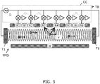
- Fig. 3 shows an embodiment similar to Fig. 1 except for the use of 6 separate receiver transducers R1-R6 arranged along the flow tube wall. The responses from these receiver transducers R1-R6 are then combined in the processing of the control circuit to result in one single measure of turbidity TB.
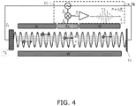
- Fig. 4 illustrates an alternative embodiment of the invention. Compared to the embodiment of the invention of Fig. 1 , this embodiment comprises only one transducer T1, and the ultrasonic wave is a travelling wave, i.e. a non-standing wave, as it is only scarcely reflected at the section end E2, or not at all.
- the ultrasonic wave is a travelling wave, i.e. a non-standing wave, as it is only scarcely reflected at the section end E2, or not at all.
- the intensity response from particle scattering will not be enhanced by the cavity build up enhancement factor, but it will still exist owing to the Doppler effect.
- the expected frequency remains f s , as described above.
- Fig. 5 shows a system embodiment.
- Two groups G1, G2 of water meters W_M are connected to measure consumed water at respective consumers on a water utility network U_N.
- the water meters W_M are arranged to measure turbidity according to the present invention, preferably using one or two ultrasonic transducers which are also involved in flow rate measurement for generating a measure of consumed water.
- Consumed water data and turbidity data are transmitted wirelessly by the water meters W_M to a central communication module which extracts the turbidity data TB_D which are then applied to a data processing DP for further analysis.
- a central communication module which extracts the turbidity data TB_D which are then applied to a data processing DP for further analysis.
- turbidity data TB_D may be used to generally monitor water quality delivered to the consumers.
- Fig. 6 shows the variation of the residual frequency f s with the flow velocity v.
- a device according to the invention as sketched with Fig. 1 was connected to a flow system having a constant turbidity.
- the transducer was driven with a constant frequency in the range 5-15 MHz and an external time-of-flight flow meter was measuring the flow rate.
- the signal from a receiver transducer, placed in the turbidity measurement section, was collected and its frequency shift fs analyzed.
- the flow velocity based on flow measurement is shown on the x-axis.
- the y-axis represent the frequency shift where the carrier frequency has been used as units. As can be seen from the figure, the frequency shift varies linearly with flow velocity according to the principle of the residual oscillation frequency of the invention.
- Fig. 7 shows the variation of the intensity of the frequency shifted signal vs. the turbidity level.
- the setup described in Fig. 6 was employed with a constant flow velocity, i.e. the frequency shift is constant.
- a series of measurement with varying turbidity (based on a 4000 NTU polystyrene standard) of the fluid flow was conducted.
- the intensity of the frequency shifted signal is analyzed and plotted as a function of the turbidity. A clear monotonic correspondence is seen between the turbidity and receiver response, even over the broad operational range of the sensor.
- Fig. 8 shows steps of a method embodiment for measurement of turbidity of a fluid flowing in a flow tube.
- an ultrasound signal is transmitted T_US_F1 at a first frequency from a first transducer trough the fluid, to generate a first ultrasonic standing wave in the flow tube.
- a response is received R_US_1 by means of a receiver transducer capturing ultrasonic signals scattered on particles in the fluid, and generating G_TB a signal indicative of the turbidity of the fluid in response to signals received from the receiver transducer.
- another ultrasonic signal is transmitted T_US_F2 from the transducer at a second frequency which is lower than the first frequency.
- a response thereto is received R_US_2 at a second transducer, and in response a signal indicative of flow rate of fluid flowing in the flow tube is generated G_FR accordingly.
- this flow rate is used in the generation of the signal indicative of the turbidity.
- the invention provides a turbidity measurement device for measuring turbidity of a fluid flowing in a flow tube.
- a first transducer transmits ultrasonic signals through the fluid in the turbidity measurement section so as to provide a first ultrasonic wave between the first and second section ends.
- a receiver transducer receives the ultrasonic scattered response from particles in the fluid flowing through the turbidity measurement section.
- a control circuit operates the transducers and generates a signal indicative of the turbidity of the fluid in response to signals received from the receiver transducer.
- the device may comprise a second transducer for generating a second ultrasonic wave with the same frequency, and further the two transducer may be used to generate a measure of flow rate by means of known ultrasonic techniques.
- This flow rate may be used in the calculation of a measure of turbidity.
- Both turbidity facilities and flow rate facilities may be integrated in a consumption meter, such as a heat meter or a water meter.
Landscapes
- Physics & Mathematics (AREA)
- General Physics & Mathematics (AREA)
- Biochemistry (AREA)
- General Health & Medical Sciences (AREA)
- Health & Medical Sciences (AREA)
- Life Sciences & Earth Sciences (AREA)
- Chemical & Material Sciences (AREA)
- Analytical Chemistry (AREA)
- Pathology (AREA)
- Immunology (AREA)
- Acoustics & Sound (AREA)
- Electromagnetism (AREA)
- Fluid Mechanics (AREA)
- Measuring Volume Flow (AREA)
- Signal Processing (AREA)
- Engineering & Computer Science (AREA)
- Investigating Or Analyzing Materials By The Use Of Ultrasonic Waves (AREA)
- Arrangements For Transmission Of Measured Signals (AREA)
Priority Applications (1)
| Application Number | Priority Date | Filing Date | Title |
|---|---|---|---|
| PL16736786T PL3317658T3 (pl) | 2015-07-03 | 2016-07-01 | Czujnik mętności oparty na pomiarach ultradźwiękowych |
Applications Claiming Priority (4)
| Application Number | Priority Date | Filing Date | Title |
|---|---|---|---|
| EP15175269.8A EP3112820A1 (en) | 2015-07-03 | 2015-07-03 | Fluid consumption meter with noise sensor |
| EP15175271.4A EP3112823A1 (en) | 2015-07-03 | 2015-07-03 | System for monitoring a utility network |
| EP15175270.6A EP3112856A1 (en) | 2015-07-03 | 2015-07-03 | Turbidity sensor based on ultrasound measurements |
| PCT/DK2016/050235 WO2017005268A1 (en) | 2015-07-03 | 2016-07-01 | Turbidity sensor based on ultrasound measurements |
Publications (2)
| Publication Number | Publication Date |
|---|---|
| EP3317658A1 EP3317658A1 (en) | 2018-05-09 |
| EP3317658B1 true EP3317658B1 (en) | 2020-09-02 |
Family
ID=56296844
Family Applications (8)
| Application Number | Title | Priority Date | Filing Date |
|---|---|---|---|
| EP16736786.1A Active EP3317658B1 (en) | 2015-07-03 | 2016-07-01 | Turbidity sensor based on ultrasound measurements |
| EP21152899.7A Active EP3828513B1 (en) | 2015-07-03 | 2016-07-04 | Fluid consumption meter with noise sensor |
| EP21152904.5A Active EP3828514B1 (en) | 2015-07-03 | 2016-07-04 | Fluid consumption meter with noise sensor |
| EP21152903.7A Active EP3845867B1 (en) | 2015-07-03 | 2016-07-04 | Fluid consumption meter with noise sensor and method of measuring a flow rate of a fluid by means of the consumption meter with noise sensor |
| EP16733998.5A Active EP3317618B1 (en) | 2015-07-03 | 2016-07-04 | Fluid consumption meter with noise sensor |
| EP24154341.2A Pending EP4336179A3 (en) | 2015-07-03 | 2016-07-04 | Fluid consumption meter with noise sensor |
| EP21152894.8A Active EP3828511B1 (en) | 2015-07-03 | 2016-07-04 | Fluid consumption meter with noise sensor |
| EP21152897.1A Active EP3828512B1 (en) | 2015-07-03 | 2016-07-04 | Fluid consumption meter with noise sensor |
Family Applications After (7)
| Application Number | Title | Priority Date | Filing Date |
|---|---|---|---|
| EP21152899.7A Active EP3828513B1 (en) | 2015-07-03 | 2016-07-04 | Fluid consumption meter with noise sensor |
| EP21152904.5A Active EP3828514B1 (en) | 2015-07-03 | 2016-07-04 | Fluid consumption meter with noise sensor |
| EP21152903.7A Active EP3845867B1 (en) | 2015-07-03 | 2016-07-04 | Fluid consumption meter with noise sensor and method of measuring a flow rate of a fluid by means of the consumption meter with noise sensor |
| EP16733998.5A Active EP3317618B1 (en) | 2015-07-03 | 2016-07-04 | Fluid consumption meter with noise sensor |
| EP24154341.2A Pending EP4336179A3 (en) | 2015-07-03 | 2016-07-04 | Fluid consumption meter with noise sensor |
| EP21152894.8A Active EP3828511B1 (en) | 2015-07-03 | 2016-07-04 | Fluid consumption meter with noise sensor |
| EP21152897.1A Active EP3828512B1 (en) | 2015-07-03 | 2016-07-04 | Fluid consumption meter with noise sensor |
Country Status (8)
| Country | Link |
|---|---|
| US (5) | US10379084B2 (da) |
| EP (8) | EP3317658B1 (da) |
| CN (5) | CN107923880B (da) |
| DK (2) | DK3317658T3 (da) |
| ES (1) | ES2898614T3 (da) |
| LT (2) | LT3317658T (da) |
| PL (2) | PL3317658T3 (da) |
| WO (3) | WO2017005268A1 (da) |
Families Citing this family (40)
| Publication number | Priority date | Publication date | Assignee | Title |
|---|---|---|---|---|
| LT3317658T (lt) * | 2015-07-03 | 2020-12-10 | Kamstrup A/S | Drumstumo jutiklis, pagrįstas ultragarsiniais matavimais |
| EP3299774A1 (en) * | 2016-09-21 | 2018-03-28 | Kamstrup A/S | Ultrasonic flowmeter and method using partial flow measurements |
| AU2017341676B2 (en) * | 2016-10-13 | 2020-11-26 | South East Water Corporation | Vibration sensor for fluid leak detection |
| US20180217102A1 (en) * | 2017-01-30 | 2018-08-02 | Jared Negussie Wolde Michael | Ultrasonic flow meter configured to detect impurities in a fluid |
| EP3367072B1 (de) * | 2017-02-24 | 2019-01-02 | SICK Engineering GmbH | Strömungsmessung mit ultraschall |
| DE102017011201B4 (de) | 2017-12-05 | 2023-01-26 | Diehl Metering Gmbh | Verfahren zur Betriebsüberwachung eines Fluidzählers sowie Fluidzähler |
| CN109187739B (zh) * | 2018-09-12 | 2021-12-07 | 浙江理工大学 | 基于超声波衰减实现混合液体浊度测量的系统及方法 |
| CN109404745B (zh) * | 2018-12-18 | 2024-04-05 | 杨启敖 | 带超声波的漏水保护器 |
| CN109404744B (zh) * | 2018-12-18 | 2024-01-16 | 杨启敖 | 带前置过滤的漏水保护装置 |
| WO2020183720A1 (ja) * | 2019-03-14 | 2020-09-17 | オムロン株式会社 | 流量測定装置 |
| CN110057908B (zh) * | 2019-04-10 | 2024-07-12 | 宁波水表(集团)股份有限公司 | 基于超声波的供水管网浑浊度在线测量装置 |
| CN109974800A (zh) * | 2019-04-11 | 2019-07-05 | 无锡洋湃科技有限公司 | 基于谐振和差压测量的湿气流量计 |
| DE102019206997B4 (de) * | 2019-05-14 | 2021-11-11 | Fraunhofer-Gesellschaft zur Förderung der angewandten Forschung e.V. | System zur zerstörungsfreien Prüfung von Bauteilen |
| JP7356818B2 (ja) * | 2019-05-23 | 2023-10-05 | 愛知時計電機株式会社 | 異物混入位置の推定方法及び流量計 |
| FR3099827B1 (fr) * | 2019-08-09 | 2021-10-15 | Sagemcom Energy & Telecom Sas | Procédé de surveillance d’un ensemble de compteurs |
| DE102019127409A1 (de) * | 2019-10-11 | 2021-04-15 | Rosen Swiss Ag | Verfahren zur Leckerkennung |
| CN112903046B (zh) | 2019-11-19 | 2025-06-13 | 卡姆鲁普股份有限公司 | 模块化超声耗量表 |
| EP4065946B1 (en) | 2019-11-26 | 2025-09-17 | Kamstrup A/S | Fluid consumption meter and leak detection system |
| CN110726698B (zh) * | 2019-11-28 | 2022-02-22 | 浙江农林大学 | 一种城市河道生态智能监测母站的浊度监测方法 |
| DK180728B1 (en) * | 2020-03-10 | 2022-02-08 | Kamstrup As | System and method for acoustic leak detection |
| WO2021182696A1 (ko) * | 2020-03-12 | 2021-09-16 | 주식회사 위플랫 | 누수음 탐지 시스템 |
| FR3109214B1 (fr) * | 2020-04-09 | 2022-09-02 | Sagemcom Energy & Telecom Sas | Procédé de détection et de localisation d’une fuite de fluide |
| WO2022035811A1 (en) * | 2020-08-13 | 2022-02-17 | Alarm.Com Incorporated | Periodic water leak detection |
| CN114441632A (zh) * | 2020-10-30 | 2022-05-06 | 上海科闫系统科技有限公司 | 水处理系统阻垢效果在线检测装置及方法 |
| EP4019908B1 (en) * | 2020-12-28 | 2024-01-17 | Kamstrup A/S | Fluid consumption meter and method for detecting sound in a piping system |
| CN112857490A (zh) * | 2021-01-15 | 2021-05-28 | 深圳市宏电技术股份有限公司 | 一种流量计算装置和计算方法 |
| EP4071454B1 (en) | 2021-04-08 | 2025-01-15 | Kamstrup A/S | Method for locating a leak in a water supply network |
| EP4538669A3 (de) * | 2021-04-30 | 2025-07-02 | Kamstrup A/S | Verfahren zur akustischen lecksuche in einem fernwärmeleitungsnetz |
| EP4095503A1 (en) | 2021-05-26 | 2022-11-30 | Kamstrup A/S | Time synchronized leak detection system |
| WO2023030597A1 (en) | 2021-09-06 | 2023-03-09 | Kamstrup A/S | System and method for acoustic leak detection in a utility distribution system |
| DE102021129099A1 (de) | 2021-11-09 | 2023-05-11 | Diehl Metering Gmbh | Druckermittlung mittels piezokeramischem Ultraschall-Wandler |
| CN114485820A (zh) * | 2022-01-12 | 2022-05-13 | 肇庆奥迪威传感科技有限公司 | 流量传感器 |
| KR102881137B1 (ko) * | 2022-01-20 | 2025-11-04 | 양강석 | 초음파 센서를 이용한 유수의 탁도 측정 장치 |
| US11573098B1 (en) * | 2022-06-08 | 2023-02-07 | King Fahd University Of Petroleum And Minerals | Method and system to detect non-technical losses in an electrical power system |
| DE102022122181A1 (de) * | 2022-09-01 | 2024-03-07 | Krohne Ag | Verfahren zum Betreiben eines Ultraschalldurchflussmessgeräts und Ultraschalldurchflussmessgerät |
| IT202300014229A1 (it) * | 2023-07-07 | 2025-01-07 | Elettrotecnica Rold Srl | Metodo ed apparato per il monitoraggio e il controllo della qualita’ dell’acqua utilizzata in elettrodomestici |
| CN116608917B (zh) * | 2023-07-19 | 2023-09-22 | 成都秦川物联网科技股份有限公司 | 气体超声波计量仪表计量抗扰方法与智慧燃气物联网系统 |
| EP4513149A1 (en) * | 2023-08-23 | 2025-02-26 | Kamstrup A/S | Utility meter with pressure transient detection |
| CN119023163B (zh) * | 2024-10-28 | 2024-12-20 | 艾肯(江苏)工业技术有限公司 | 一种基于超声波的阀门泄漏微流量检测装置 |
| CN119880825B (zh) * | 2025-03-19 | 2025-07-29 | 安徽恒宇环保设备制造股份有限公司 | 一种用于地表水的水质监测方法及系统 |
Family Cites Families (72)
| Publication number | Priority date | Publication date | Assignee | Title |
|---|---|---|---|---|
| US3109112A (en) * | 1962-03-13 | 1963-10-29 | Robert A Lester | Double frequency transducer |
| GB1121824A (en) * | 1965-12-14 | 1968-07-31 | Exxon Research Engineering Co | Pipeline leak detector |
| NL6600966A (da) * | 1965-12-22 | 1967-07-27 | ||
| US3849002A (en) * | 1973-05-11 | 1974-11-19 | Hach Chemical Co | Method and apparatus for eliminating air during fluid turbidity measurement |
| US3906791A (en) * | 1973-10-01 | 1975-09-23 | Panametrics | Area averaging ultrasonic flowmeters |
| US4527420A (en) * | 1982-06-11 | 1985-07-09 | Micro Pure Systems, Inc. | Ultrasonic particulate sensing |
| US6248077B1 (en) | 1982-07-19 | 2001-06-19 | Edwards Lifesciences Corp. | System for sensing a characteristic of fluid flowing to or from a body |
| US4476877A (en) | 1982-08-16 | 1984-10-16 | Gould Inc. | Fluid temperature sensor |
| US4542644A (en) * | 1983-09-26 | 1985-09-24 | The United States Of America As Represented By The United States Department Of Energy | Void/particulate detector |
| US4740709A (en) * | 1986-04-10 | 1988-04-26 | The United States Of America As Represented By The Department Of Health And Human Services | Method of sensing fluid properties independent of bubble concentrations |
| US5151085A (en) * | 1989-04-28 | 1992-09-29 | Olympus Optical Co., Ltd. | Apparatus for generating ultrasonic oscillation |
| JP2878804B2 (ja) * | 1989-09-19 | 1999-04-05 | 東京瓦斯株式会社 | 配管の異常監視装置 |
| NZ243294A (en) * | 1991-06-25 | 1995-04-27 | Commw Scient Ind Res Org | Time of flight of acoustic wave packets through fluid: reduction of higher order acoustic mode effects |
| JPH05209822A (ja) * | 1992-01-30 | 1993-08-20 | Hitachi Ltd | 粒子計数装置 |
| EP0690974A4 (en) | 1993-03-09 | 1996-05-22 | Commw Scient Ind Res Org | LIQUID METER DESIGN |
| US5710377A (en) * | 1995-10-17 | 1998-01-20 | The United States Of America As Represented By The Administrator Of The National Aeronautics And Space Administration | Ultrasonic leak detection system |
| US5688406A (en) * | 1996-02-28 | 1997-11-18 | The United States Of America As Represented By The Secretary Of The Navy | Method and apparatus for separating particulate from a flowing fluid |
| DE19713526A1 (de) | 1997-04-01 | 1998-10-08 | Elster Produktion Gmbh | Vorrichtung zur Ultraschall-Durchflußmessung |
| US5969237A (en) * | 1997-10-09 | 1999-10-19 | Baker Hughes Incorporated | Measurement and control of asphaltene agglomeration in hydrocarbon Liquids |
| FI111433B (fi) * | 1998-01-29 | 2003-07-15 | Nokia Corp | Menetelmä tiedonsiirron salaamiseksi ja solukkoradiojärjestelmä |
| IT1311771B1 (it) * | 1999-02-24 | 2002-03-19 | Giorgio Bergamini | Misuratore perfezionato della portata di gas con gli ultrasuoni basato su specchi parabolici. |
| KR100487690B1 (ko) | 1999-06-24 | 2005-05-06 | 마쯔시다덴기산교 가부시키가이샤 | 유량계 |
| WO2001031308A1 (de) * | 1999-10-26 | 2001-05-03 | Peter Martinek | Verfahren und messsonde zur durchführung von messungen in wasserversorgungssystemen |
| CN1283780A (zh) * | 2000-08-28 | 2001-02-14 | 浙江省苍南众星实业有限公司 | 管道内流体流量的测量方法及其声波流量计 |
| JP2002116073A (ja) * | 2000-10-10 | 2002-04-19 | Osaka Gas Co Ltd | 流量測定方法 |
| DE10051534A1 (de) | 2000-10-18 | 2002-04-25 | Sensorentechnologie Gettorf Gm | Sensorsystem und Verfahren |
| CN1708674A (zh) * | 2002-04-24 | 2005-12-14 | 塞德拉公司 | 测量在管道中流动的流体中具有悬浮的固体微粒的混合物的参数的装置和方法 |
| DE10227918A1 (de) * | 2002-06-21 | 2004-01-15 | Bühler AG | Verfahren zum Bestimmen rheologischer Parameter eines Fluids |
| CN1184483C (zh) * | 2002-12-24 | 2005-01-12 | 上海大学 | 集成式浆体浓度流量在线测量方法和系统 |
| WO2004063741A2 (en) * | 2003-01-13 | 2004-07-29 | Cidra Corporation | Apparatus for measuring parameters of a flowing multiphase fluid mixture |
| CN100504311C (zh) * | 2003-01-13 | 2009-06-24 | 塞德拉公司 | 使用超声波传感器阵列确定管道内的流体速度的设备和方法 |
| JP4275990B2 (ja) | 2003-05-20 | 2009-06-10 | 株式会社キーエンス | 流量センサ |
| ATE329240T1 (de) * | 2003-10-08 | 2006-06-15 | Innova Airtech Instr As | Ultraschallgasleckdetektor mit einer vorrichtung zur detektoruntersuchung |
| NO318971B1 (no) * | 2003-10-30 | 2005-05-30 | Statoil Asa | Anordning og system for tilstandskontroll av en rorledning ved bruk av ultralyd |
| US6983208B2 (en) * | 2003-11-24 | 2006-01-03 | Mgd Technologies, Inc. | Method and apparatus for combined measurements of concentration, distribution and flow velocity of suspended solids |
| WO2005119182A1 (ja) * | 2004-06-01 | 2005-12-15 | Avance Techne Accent Corp. | 流体の流量測定方法及び流量測定装置 |
| DE102004057695B4 (de) * | 2004-11-30 | 2009-12-24 | Abb Ag | Magnetisch induktiver Durchflussmesser mit einem Messrohr aus Kunststoff |
| CN100541170C (zh) * | 2004-12-30 | 2009-09-16 | 中国科学院海洋研究所 | 海洋声学浊度传感器 |
| CN1332183C (zh) * | 2005-08-10 | 2007-08-15 | 陈宇 | 流体的流量检测装置 |
| DE102006027422B4 (de) * | 2006-06-13 | 2014-02-06 | Continental Automotive Gmbh | Verfahren und Vorrichtung zum Überwachen eines Abgasturboladers |
| EP2130004A1 (en) | 2006-10-31 | 2009-12-09 | IMI Vision Limited | Ultrasonic flow-rate measurement device and system |
| WO2008117531A1 (ja) * | 2007-03-23 | 2008-10-02 | Panasonic Corporation | ガス器具監視装置 |
| BRPI0817874A2 (pt) * | 2007-10-10 | 2015-03-31 | Tecwel As | Método e sistema para registrar e mensuar vazamentos e fluxos |
| CN201107066Y (zh) * | 2007-11-02 | 2008-08-27 | 重庆钢铁(集团)有限责任公司 | 超声波流量计用耐高温换能器 |
| EP2083251A1 (en) | 2007-12-13 | 2009-07-29 | Kamstrup A/S | A consumption meter with at least two casing parts |
| DE102008019989B4 (de) | 2008-04-21 | 2010-07-01 | Mib Gmbh Messtechnik Und Industrieberatung | Ultraschall-Messanordnung |
| CN201222055Y (zh) * | 2008-05-27 | 2009-04-15 | 成都敏博科技有限公司 | 超声波气体浓度测量装置 |
| US8085156B2 (en) * | 2009-04-08 | 2011-12-27 | Rosemount Inc. | RF cavity-based process fluid sensor |
| EP2336732A1 (en) * | 2009-12-15 | 2011-06-22 | Kamstrup A/S | Consumption Meter with Flow Part and Housing Formed by a Monolithic Polymer Structure |
| US8665101B2 (en) * | 2009-11-16 | 2014-03-04 | Aquarius Spectrum Ltd. | System method and device for leak detection and localization in a pipe network |
| US7920983B1 (en) * | 2010-03-04 | 2011-04-05 | TaKaDu Ltd. | System and method for monitoring resources in a water utility network |
| DE102010029283A1 (de) * | 2010-05-25 | 2011-12-01 | Robert Bosch Gmbh | Ultraschallwandler zum Einsatz in einem fluiden Medium |
| US20110298635A1 (en) * | 2010-06-04 | 2011-12-08 | Bernie Yip | Self dynamo smart flow utility meter and system for flow utility real-time flow usage monitoring and control, self error and leakages monitoring |
| EP2862510B1 (en) * | 2010-06-24 | 2018-02-28 | Pioneer Corporation | Light detecting apparatus and fluid measuring apparatus |
| KR101810723B1 (ko) * | 2010-09-03 | 2017-12-19 | 로스 알라모스 내셔널 씨큐어리티 엘엘씨 | 도플러 분광법을 이용한 비침투적 입자 검출 장치 및 방법 |
| KR101844098B1 (ko) * | 2010-09-03 | 2018-03-30 | 로스 알라모스 내셔널 씨큐어리티 엘엘씨 | 파이프 내 유체의 음향 특성을 비침투적으로 결정하는 방법 |
| US7942066B1 (en) * | 2010-09-22 | 2011-05-17 | Florida Turbine Technologies, Inc. | Non-intrusive two-phase flow measurement system |
| AU2014202604B2 (en) * | 2011-02-09 | 2015-08-27 | South East Water Corporation | Wirelessly networked fluid monitoring method, system and apparatus |
| KR20140019793A (ko) | 2011-03-07 | 2014-02-17 | 로스 알라모스 내셔널 씨큐어리티 엘엘씨 | 스팀 퀄리티와 흐름의 음향적 모니터링을 위한 장치 및 방법 |
| CA2830441C (en) * | 2011-03-18 | 2019-04-02 | Cidra Corporate Services Inc. | Acoustic standing wave particle size or distribution detection |
| GB2491804B (en) * | 2011-05-11 | 2018-01-17 | Syrinix Ltd | Pipeline fault detection system and monitor unit |
| DK2758753T3 (da) * | 2011-09-23 | 2016-05-30 | Kamstrup As | Strømningsmåler med fremstående transducere |
| KR101142897B1 (ko) * | 2011-10-06 | 2012-05-10 | 웨스글로벌 주식회사 | 초음파 유량 및 농도 공용 측정 시스템 |
| EP2581715A1 (en) | 2011-10-13 | 2013-04-17 | Miitors ApS | Ultrasonic flow meter |
| WO2013059360A1 (en) * | 2011-10-17 | 2013-04-25 | Prodyne Corporation | Ultrasonic measurement of particle size distribution |
| US10508937B2 (en) * | 2012-04-12 | 2019-12-17 | Texas Instruments Incorporated | Ultrasonic flow meter |
| EP2912416B1 (en) * | 2012-10-26 | 2018-05-30 | Mueller International, LLC | Detecting leaks in a fluid distribution system |
| WO2014089122A1 (en) * | 2012-12-03 | 2014-06-12 | Patrick Rada | In medium communication system using log detector amplifier |
| WO2014089249A1 (en) * | 2012-12-04 | 2014-06-12 | Horne Stephen J | Fluid flow detection and analysis device and system |
| CN103292160B (zh) * | 2013-06-27 | 2015-11-18 | 陕西师范大学 | 管道泄漏的超声波检测装置及方法 |
| US9928724B2 (en) * | 2015-05-13 | 2018-03-27 | Rachio, Inc. | Flow characteristic detection and automatic flow shutoff |
| LT3317658T (lt) * | 2015-07-03 | 2020-12-10 | Kamstrup A/S | Drumstumo jutiklis, pagrįstas ultragarsiniais matavimais |
-
2016
- 2016-07-01 LT LTEP16736786.1T patent/LT3317658T/lt unknown
- 2016-07-01 EP EP16736786.1A patent/EP3317658B1/en active Active
- 2016-07-01 PL PL16736786T patent/PL3317658T3/pl unknown
- 2016-07-01 WO PCT/DK2016/050235 patent/WO2017005268A1/en not_active Ceased
- 2016-07-01 WO PCT/DK2016/050236 patent/WO2017005269A1/en not_active Ceased
- 2016-07-01 CN CN201680039528.7A patent/CN107923880B/zh active Active
- 2016-07-01 DK DK16736786.1T patent/DK3317658T3/da active
- 2016-07-01 US US15/741,560 patent/US10379084B2/en active Active
- 2016-07-04 CN CN202110043930.5A patent/CN112665668B/zh active Active
- 2016-07-04 LT LTEPPCT/EP2016/065697T patent/LT3317618T/lt unknown
- 2016-07-04 US US15/741,567 patent/US10921288B2/en active Active
- 2016-07-04 EP EP21152899.7A patent/EP3828513B1/en active Active
- 2016-07-04 EP EP21152904.5A patent/EP3828514B1/en active Active
- 2016-07-04 EP EP21152903.7A patent/EP3845867B1/en active Active
- 2016-07-04 EP EP16733998.5A patent/EP3317618B1/en active Active
- 2016-07-04 EP EP24154341.2A patent/EP4336179A3/en active Pending
- 2016-07-04 EP EP21152894.8A patent/EP3828511B1/en active Active
- 2016-07-04 CN CN201680039499.4A patent/CN107709938B/zh active Active
- 2016-07-04 CN CN202110043916.5A patent/CN112665667B/zh active Active
- 2016-07-04 DK DK16733998.5T patent/DK3317618T3/da active
- 2016-07-04 PL PL16733998T patent/PL3317618T3/pl unknown
- 2016-07-04 EP EP21152897.1A patent/EP3828512B1/en active Active
- 2016-07-04 WO PCT/EP2016/065697 patent/WO2017005687A1/en not_active Ceased
- 2016-07-04 ES ES16733998T patent/ES2898614T3/es active Active
- 2016-07-04 CN CN202110051512.0A patent/CN112665669B/zh active Active
-
2019
- 2019-05-31 US US16/427,836 patent/US11391699B2/en active Active
-
2020
- 2020-09-23 US US17/029,153 patent/US11852609B2/en active Active
-
2023
- 2023-11-15 US US18/509,492 patent/US12235241B2/en active Active
Non-Patent Citations (1)
| Title |
|---|
| None * |
Also Published As
Similar Documents
| Publication | Publication Date | Title |
|---|---|---|
| US11391699B2 (en) | Turbidity sensor based on ultrasound measurements | |
| US9354094B2 (en) | Apparatus and method for noninvasive particle detection using doppler spectroscopy | |
| US7624650B2 (en) | Apparatus and method for attenuating acoustic waves propagating within a pipe wall | |
| KR101810724B1 (ko) | 다상 유체 특성화 시스템 | |
| EP1899687B1 (en) | Multi-phase flow measurement system having a fluid separator | |
| EP4230969B1 (en) | Location and flow rate meter | |
| US7831398B2 (en) | Method for quantifying varying propagation characteristics of normal incident ultrasonic signals as used in correlation based flow measurement | |
| KR20140019793A (ko) | 스팀 퀄리티와 흐름의 음향적 모니터링을 위한 장치 및 방법 | |
| CN102288235A (zh) | 一种双道混合型超声波流量计及测量方法 | |
| CN103328934A (zh) | 用于确定管线中流体或流体组分的流速的装置和方法 | |
| CN109991590A (zh) | 一种在有限空间压力罐内测试换能器低频发射特性的系统与方法 | |
| CN108680234A (zh) | 一种跨冰层介质的水深测量方法 | |
| US20190154479A1 (en) | Estimating flow velocity in pipes by correlating multi-frequency signals | |
| EP3112856A1 (en) | Turbidity sensor based on ultrasound measurements | |
| US11525719B2 (en) | Estimating flow velocity by harmonic excitation of injected microbubbles | |
| JP2003194614A (ja) | 水位検知システム及び水位検知方法 | |
| CN109253396A (zh) | 一种浆液复合管道流量的检测方法及装置 | |
| CA2658849A1 (en) | Apparatus and method for attenuating acoustic waves in propagating within a pipe wall | |
| RU2640122C1 (ru) | Вихреакустический преобразователь расхода | |
| CN205300671U (zh) | 一种超声波气体流量计 | |
| AU2024219961B2 (en) | Location and flow rate meter | |
| Lazarus | The development of an ultrasonic Doppler bed-load velocimeter | |
| WO2006134199A1 (en) | Ultrasound flowmeter arrangement for determining speed of sound | |
| Gibbard | Flow measurement: New technology |
Legal Events
| Date | Code | Title | Description |
|---|---|---|---|
| STAA | Information on the status of an ep patent application or granted ep patent |
Free format text: STATUS: THE INTERNATIONAL PUBLICATION HAS BEEN MADE |
|
| PUAI | Public reference made under article 153(3) epc to a published international application that has entered the european phase |
Free format text: ORIGINAL CODE: 0009012 |
|
| STAA | Information on the status of an ep patent application or granted ep patent |
Free format text: STATUS: REQUEST FOR EXAMINATION WAS MADE |
|
| 17P | Request for examination filed |
Effective date: 20180201 |
|
| AK | Designated contracting states |
Kind code of ref document: A1 Designated state(s): AL AT BE BG CH CY CZ DE DK EE ES FI FR GB GR HR HU IE IS IT LI LT LU LV MC MK MT NL NO PL PT RO RS SE SI SK SM TR |
|
| AX | Request for extension of the european patent |
Extension state: BA ME |
|
| DAV | Request for validation of the european patent (deleted) | ||
| DAX | Request for extension of the european patent (deleted) | ||
| GRAP | Despatch of communication of intention to grant a patent |
Free format text: ORIGINAL CODE: EPIDOSNIGR1 |
|
| STAA | Information on the status of an ep patent application or granted ep patent |
Free format text: STATUS: GRANT OF PATENT IS INTENDED |
|
| RIC1 | Information provided on ipc code assigned before grant |
Ipc: G01N 29/032 20060101AFI20190715BHEP Ipc: G01M 3/24 20060101ALI20190715BHEP Ipc: G01M 3/28 20060101ALI20190715BHEP Ipc: G01F 1/66 20060101ALI20190715BHEP Ipc: G01D 4/00 20060101ALI20190715BHEP |
|
| INTG | Intention to grant announced |
Effective date: 20190821 |
|
| GRAJ | Information related to disapproval of communication of intention to grant by the applicant or resumption of examination proceedings by the epo deleted |
Free format text: ORIGINAL CODE: EPIDOSDIGR1 |
|
| STAA | Information on the status of an ep patent application or granted ep patent |
Free format text: STATUS: REQUEST FOR EXAMINATION WAS MADE |
|
| INTC | Intention to grant announced (deleted) | ||
| GRAP | Despatch of communication of intention to grant a patent |
Free format text: ORIGINAL CODE: EPIDOSNIGR1 |
|
| STAA | Information on the status of an ep patent application or granted ep patent |
Free format text: STATUS: GRANT OF PATENT IS INTENDED |
|
| RIC1 | Information provided on ipc code assigned before grant |
Ipc: G01F 1/66 20060101ALI20200115BHEP Ipc: G01N 29/032 20060101AFI20200115BHEP Ipc: G01M 3/24 20060101ALI20200115BHEP Ipc: G01M 3/28 20060101ALI20200115BHEP Ipc: G01D 4/00 20060101ALI20200115BHEP Ipc: G01N 29/50 20060101ALI20200115BHEP Ipc: G01N 29/22 20060101ALI20200115BHEP |
|
| INTG | Intention to grant announced |
Effective date: 20200203 |
|
| GRAS | Grant fee paid |
Free format text: ORIGINAL CODE: EPIDOSNIGR3 |
|
| GRAA | (expected) grant |
Free format text: ORIGINAL CODE: 0009210 |
|
| STAA | Information on the status of an ep patent application or granted ep patent |
Free format text: STATUS: THE PATENT HAS BEEN GRANTED |
|
| AK | Designated contracting states |
Kind code of ref document: B1 Designated state(s): AL AT BE BG CH CY CZ DE DK EE ES FI FR GB GR HR HU IE IS IT LI LT LU LV MC MK MT NL NO PL PT RO RS SE SI SK SM TR |
|
| REG | Reference to a national code |
Ref country code: GB Ref legal event code: FG4D |
|
| REG | Reference to a national code |
Ref country code: AT Ref legal event code: REF Ref document number: 1309429 Country of ref document: AT Kind code of ref document: T Effective date: 20200915 Ref country code: CH Ref legal event code: EP |
|
| REG | Reference to a national code |
Ref country code: DE Ref legal event code: R096 Ref document number: 602016043197 Country of ref document: DE |
|
| REG | Reference to a national code |
Ref country code: IE Ref legal event code: FG4D |
|
| REG | Reference to a national code |
Ref country code: FI Ref legal event code: FGE |
|
| REG | Reference to a national code |
Ref country code: DK Ref legal event code: T3 Effective date: 20201124 Ref country code: NO Ref legal event code: T2 Effective date: 20200902 |
|
| REG | Reference to a national code |
Ref country code: SE Ref legal event code: TRGR |
|
| REG | Reference to a national code |
Ref country code: NL Ref legal event code: FP |
|
| PG25 | Lapsed in a contracting state [announced via postgrant information from national office to epo] |
Ref country code: BG Free format text: LAPSE BECAUSE OF FAILURE TO SUBMIT A TRANSLATION OF THE DESCRIPTION OR TO PAY THE FEE WITHIN THE PRESCRIBED TIME-LIMIT Effective date: 20201202 Ref country code: GR Free format text: LAPSE BECAUSE OF FAILURE TO SUBMIT A TRANSLATION OF THE DESCRIPTION OR TO PAY THE FEE WITHIN THE PRESCRIBED TIME-LIMIT Effective date: 20201203 Ref country code: HR Free format text: LAPSE BECAUSE OF FAILURE TO SUBMIT A TRANSLATION OF THE DESCRIPTION OR TO PAY THE FEE WITHIN THE PRESCRIBED TIME-LIMIT Effective date: 20200902 |
|
| REG | Reference to a national code |
Ref country code: AT Ref legal event code: MK05 Ref document number: 1309429 Country of ref document: AT Kind code of ref document: T Effective date: 20200902 |
|
| PG25 | Lapsed in a contracting state [announced via postgrant information from national office to epo] |
Ref country code: RS Free format text: LAPSE BECAUSE OF FAILURE TO SUBMIT A TRANSLATION OF THE DESCRIPTION OR TO PAY THE FEE WITHIN THE PRESCRIBED TIME-LIMIT Effective date: 20200902 Ref country code: LV Free format text: LAPSE BECAUSE OF FAILURE TO SUBMIT A TRANSLATION OF THE DESCRIPTION OR TO PAY THE FEE WITHIN THE PRESCRIBED TIME-LIMIT Effective date: 20200902 |
|
| PG25 | Lapsed in a contracting state [announced via postgrant information from national office to epo] |
Ref country code: CZ Free format text: LAPSE BECAUSE OF FAILURE TO SUBMIT A TRANSLATION OF THE DESCRIPTION OR TO PAY THE FEE WITHIN THE PRESCRIBED TIME-LIMIT Effective date: 20200902 Ref country code: SM Free format text: LAPSE BECAUSE OF FAILURE TO SUBMIT A TRANSLATION OF THE DESCRIPTION OR TO PAY THE FEE WITHIN THE PRESCRIBED TIME-LIMIT Effective date: 20200902 Ref country code: RO Free format text: LAPSE BECAUSE OF FAILURE TO SUBMIT A TRANSLATION OF THE DESCRIPTION OR TO PAY THE FEE WITHIN THE PRESCRIBED TIME-LIMIT Effective date: 20200902 Ref country code: PT Free format text: LAPSE BECAUSE OF FAILURE TO SUBMIT A TRANSLATION OF THE DESCRIPTION OR TO PAY THE FEE WITHIN THE PRESCRIBED TIME-LIMIT Effective date: 20210104 Ref country code: EE Free format text: LAPSE BECAUSE OF FAILURE TO SUBMIT A TRANSLATION OF THE DESCRIPTION OR TO PAY THE FEE WITHIN THE PRESCRIBED TIME-LIMIT Effective date: 20200902 |
|
| PG25 | Lapsed in a contracting state [announced via postgrant information from national office to epo] |
Ref country code: IS Free format text: LAPSE BECAUSE OF FAILURE TO SUBMIT A TRANSLATION OF THE DESCRIPTION OR TO PAY THE FEE WITHIN THE PRESCRIBED TIME-LIMIT Effective date: 20210102 Ref country code: ES Free format text: LAPSE BECAUSE OF FAILURE TO SUBMIT A TRANSLATION OF THE DESCRIPTION OR TO PAY THE FEE WITHIN THE PRESCRIBED TIME-LIMIT Effective date: 20200902 Ref country code: AL Free format text: LAPSE BECAUSE OF FAILURE TO SUBMIT A TRANSLATION OF THE DESCRIPTION OR TO PAY THE FEE WITHIN THE PRESCRIBED TIME-LIMIT Effective date: 20200902 Ref country code: AT Free format text: LAPSE BECAUSE OF FAILURE TO SUBMIT A TRANSLATION OF THE DESCRIPTION OR TO PAY THE FEE WITHIN THE PRESCRIBED TIME-LIMIT Effective date: 20200902 |
|
| REG | Reference to a national code |
Ref country code: DE Ref legal event code: R097 Ref document number: 602016043197 Country of ref document: DE |
|
| PG25 | Lapsed in a contracting state [announced via postgrant information from national office to epo] |
Ref country code: SK Free format text: LAPSE BECAUSE OF FAILURE TO SUBMIT A TRANSLATION OF THE DESCRIPTION OR TO PAY THE FEE WITHIN THE PRESCRIBED TIME-LIMIT Effective date: 20200902 |
|
| PLBE | No opposition filed within time limit |
Free format text: ORIGINAL CODE: 0009261 |
|
| STAA | Information on the status of an ep patent application or granted ep patent |
Free format text: STATUS: NO OPPOSITION FILED WITHIN TIME LIMIT |
|
| 26N | No opposition filed |
Effective date: 20210603 |
|
| PG25 | Lapsed in a contracting state [announced via postgrant information from national office to epo] |
Ref country code: SI Free format text: LAPSE BECAUSE OF FAILURE TO SUBMIT A TRANSLATION OF THE DESCRIPTION OR TO PAY THE FEE WITHIN THE PRESCRIBED TIME-LIMIT Effective date: 20200902 |
|
| PG25 | Lapsed in a contracting state [announced via postgrant information from national office to epo] |
Ref country code: IT Free format text: LAPSE BECAUSE OF FAILURE TO SUBMIT A TRANSLATION OF THE DESCRIPTION OR TO PAY THE FEE WITHIN THE PRESCRIBED TIME-LIMIT Effective date: 20200902 |
|
| REG | Reference to a national code |
Ref country code: CH Ref legal event code: PL |
|
| PG25 | Lapsed in a contracting state [announced via postgrant information from national office to epo] |
Ref country code: MC Free format text: LAPSE BECAUSE OF FAILURE TO SUBMIT A TRANSLATION OF THE DESCRIPTION OR TO PAY THE FEE WITHIN THE PRESCRIBED TIME-LIMIT Effective date: 20200902 |
|
| REG | Reference to a national code |
Ref country code: BE Ref legal event code: MM Effective date: 20210731 |
|
| PG25 | Lapsed in a contracting state [announced via postgrant information from national office to epo] |
Ref country code: LI Free format text: LAPSE BECAUSE OF NON-PAYMENT OF DUE FEES Effective date: 20210731 Ref country code: CH Free format text: LAPSE BECAUSE OF NON-PAYMENT OF DUE FEES Effective date: 20210731 |
|
| PG25 | Lapsed in a contracting state [announced via postgrant information from national office to epo] |
Ref country code: LU Free format text: LAPSE BECAUSE OF NON-PAYMENT OF DUE FEES Effective date: 20210701 |
|
| PG25 | Lapsed in a contracting state [announced via postgrant information from national office to epo] |
Ref country code: IE Free format text: LAPSE BECAUSE OF NON-PAYMENT OF DUE FEES Effective date: 20210701 Ref country code: BE Free format text: LAPSE BECAUSE OF NON-PAYMENT OF DUE FEES Effective date: 20210731 |
|
| PG25 | Lapsed in a contracting state [announced via postgrant information from national office to epo] |
Ref country code: HU Free format text: LAPSE BECAUSE OF FAILURE TO SUBMIT A TRANSLATION OF THE DESCRIPTION OR TO PAY THE FEE WITHIN THE PRESCRIBED TIME-LIMIT; INVALID AB INITIO Effective date: 20160701 |
|
| P01 | Opt-out of the competence of the unified patent court (upc) registered |
Effective date: 20230517 |
|
| PG25 | Lapsed in a contracting state [announced via postgrant information from national office to epo] |
Ref country code: CY Free format text: LAPSE BECAUSE OF FAILURE TO SUBMIT A TRANSLATION OF THE DESCRIPTION OR TO PAY THE FEE WITHIN THE PRESCRIBED TIME-LIMIT Effective date: 20200902 |
|
| PG25 | Lapsed in a contracting state [announced via postgrant information from national office to epo] |
Ref country code: MK Free format text: LAPSE BECAUSE OF FAILURE TO SUBMIT A TRANSLATION OF THE DESCRIPTION OR TO PAY THE FEE WITHIN THE PRESCRIBED TIME-LIMIT Effective date: 20200902 |
|
| PG25 | Lapsed in a contracting state [announced via postgrant information from national office to epo] |
Ref country code: MT Free format text: LAPSE BECAUSE OF FAILURE TO SUBMIT A TRANSLATION OF THE DESCRIPTION OR TO PAY THE FEE WITHIN THE PRESCRIBED TIME-LIMIT Effective date: 20200902 |
|
| PGFP | Annual fee paid to national office [announced via postgrant information from national office to epo] |
Ref country code: PL Payment date: 20250624 Year of fee payment: 10 |
|
| PGFP | Annual fee paid to national office [announced via postgrant information from national office to epo] |
Ref country code: LT Payment date: 20250623 Year of fee payment: 10 |
|
| PGFP | Annual fee paid to national office [announced via postgrant information from national office to epo] |
Ref country code: NL Payment date: 20250721 Year of fee payment: 10 |
|
| PGFP | Annual fee paid to national office [announced via postgrant information from national office to epo] |
Ref country code: FI Payment date: 20250725 Year of fee payment: 10 |
|
| PGFP | Annual fee paid to national office [announced via postgrant information from national office to epo] |
Ref country code: DK Payment date: 20250725 Year of fee payment: 10 Ref country code: DE Payment date: 20250722 Year of fee payment: 10 |
|
| PGFP | Annual fee paid to national office [announced via postgrant information from national office to epo] |
Ref country code: NO Payment date: 20250725 Year of fee payment: 10 |
|
| PGFP | Annual fee paid to national office [announced via postgrant information from national office to epo] |
Ref country code: GB Payment date: 20250722 Year of fee payment: 10 |
|
| PGFP | Annual fee paid to national office [announced via postgrant information from national office to epo] |
Ref country code: FR Payment date: 20250725 Year of fee payment: 10 |
|
| PGFP | Annual fee paid to national office [announced via postgrant information from national office to epo] |
Ref country code: SE Payment date: 20250722 Year of fee payment: 10 |
|
| PG25 | Lapsed in a contracting state [announced via postgrant information from national office to epo] |
Ref country code: TR Free format text: LAPSE BECAUSE OF FAILURE TO SUBMIT A TRANSLATION OF THE DESCRIPTION OR TO PAY THE FEE WITHIN THE PRESCRIBED TIME-LIMIT Effective date: 20200902 |