EP3317618B1 - Flüssigkeitsverbrauchsmesser mit geräuschsensor - Google Patents
Flüssigkeitsverbrauchsmesser mit geräuschsensor Download PDFInfo
- Publication number
- EP3317618B1 EP3317618B1 EP16733998.5A EP16733998A EP3317618B1 EP 3317618 B1 EP3317618 B1 EP 3317618B1 EP 16733998 A EP16733998 A EP 16733998A EP 3317618 B1 EP3317618 B1 EP 3317618B1
- Authority
- EP
- European Patent Office
- Prior art keywords
- fluid
- flow tube
- noise level
- circuit
- noise
- Prior art date
- Legal status (The legal status is an assumption and is not a legal conclusion. Google has not performed a legal analysis and makes no representation as to the accuracy of the status listed.)
- Active
Links
Images


Classifications
-
- G—PHYSICS
- G01—MEASURING; TESTING
- G01N—INVESTIGATING OR ANALYSING MATERIALS BY DETERMINING THEIR CHEMICAL OR PHYSICAL PROPERTIES
- G01N29/00—Investigating or analysing materials by the use of ultrasonic, sonic or infrasonic waves; Visualisation of the interior of objects by transmitting ultrasonic or sonic waves through the object
- G01N29/02—Analysing fluids
- G01N29/032—Analysing fluids by measuring attenuation of acoustic waves
-
- G—PHYSICS
- G01—MEASURING; TESTING
- G01D—MEASURING NOT SPECIALLY ADAPTED FOR A SPECIFIC VARIABLE; ARRANGEMENTS FOR MEASURING TWO OR MORE VARIABLES NOT COVERED IN A SINGLE OTHER SUBCLASS; TARIFF METERING APPARATUS; MEASURING OR TESTING NOT OTHERWISE PROVIDED FOR
- G01D4/00—Tariff metering apparatus
- G01D4/002—Remote reading of utility meters
- G01D4/004—Remote reading of utility meters to a fixed location
-
- G—PHYSICS
- G01—MEASURING; TESTING
- G01F—MEASURING VOLUME, VOLUME FLOW, MASS FLOW OR LIQUID LEVEL; METERING BY VOLUME
- G01F1/00—Measuring the volume flow or mass flow of fluid or fluent solid material wherein the fluid passes through a meter in a continuous flow
- G01F1/66—Measuring the volume flow or mass flow of fluid or fluent solid material wherein the fluid passes through a meter in a continuous flow by measuring frequency, phase shift or propagation time of electromagnetic or other waves, e.g. using ultrasonic flowmeters
- G01F1/666—Measuring the volume flow or mass flow of fluid or fluent solid material wherein the fluid passes through a meter in a continuous flow by measuring frequency, phase shift or propagation time of electromagnetic or other waves, e.g. using ultrasonic flowmeters by detecting noise and sounds generated by the flowing fluid
-
- G—PHYSICS
- G01—MEASURING; TESTING
- G01M—TESTING STATIC OR DYNAMIC BALANCE OF MACHINES OR STRUCTURES; TESTING OF STRUCTURES OR APPARATUS, NOT OTHERWISE PROVIDED FOR
- G01M3/00—Investigating fluid-tightness of structures
- G01M3/02—Investigating fluid-tightness of structures by using fluid or vacuum
- G01M3/04—Investigating fluid-tightness of structures by using fluid or vacuum by detecting the presence of fluid at the leakage point
- G01M3/24—Investigating fluid-tightness of structures by using fluid or vacuum by detecting the presence of fluid at the leakage point using infrasonic, sonic or ultrasonic vibrations
- G01M3/243—Investigating fluid-tightness of structures by using fluid or vacuum by detecting the presence of fluid at the leakage point using infrasonic, sonic or ultrasonic vibrations for pipes
-
- G—PHYSICS
- G01—MEASURING; TESTING
- G01M—TESTING STATIC OR DYNAMIC BALANCE OF MACHINES OR STRUCTURES; TESTING OF STRUCTURES OR APPARATUS, NOT OTHERWISE PROVIDED FOR
- G01M3/00—Investigating fluid-tightness of structures
- G01M3/02—Investigating fluid-tightness of structures by using fluid or vacuum
- G01M3/26—Investigating fluid-tightness of structures by using fluid or vacuum by measuring rate of loss or gain of fluid, e.g. by pressure-responsive devices, by flow detectors
- G01M3/28—Investigating fluid-tightness of structures by using fluid or vacuum by measuring rate of loss or gain of fluid, e.g. by pressure-responsive devices, by flow detectors for pipes, cables or tubes; for pipe joints or seals; for valves ; for welds
- G01M3/2807—Investigating fluid-tightness of structures by using fluid or vacuum by measuring rate of loss or gain of fluid, e.g. by pressure-responsive devices, by flow detectors for pipes, cables or tubes; for pipe joints or seals; for valves ; for welds for pipes
- G01M3/2815—Investigating fluid-tightness of structures by using fluid or vacuum by measuring rate of loss or gain of fluid, e.g. by pressure-responsive devices, by flow detectors for pipes, cables or tubes; for pipe joints or seals; for valves ; for welds for pipes using pressure measurements
-
- G—PHYSICS
- G01—MEASURING; TESTING
- G01N—INVESTIGATING OR ANALYSING MATERIALS BY DETERMINING THEIR CHEMICAL OR PHYSICAL PROPERTIES
- G01N29/00—Investigating or analysing materials by the use of ultrasonic, sonic or infrasonic waves; Visualisation of the interior of objects by transmitting ultrasonic or sonic waves through the object
- G01N29/22—Details, e.g. general constructional or apparatus details
- G01N29/222—Constructional or flow details for analysing fluids
-
- G—PHYSICS
- G01—MEASURING; TESTING
- G01N—INVESTIGATING OR ANALYSING MATERIALS BY DETERMINING THEIR CHEMICAL OR PHYSICAL PROPERTIES
- G01N29/00—Investigating or analysing materials by the use of ultrasonic, sonic or infrasonic waves; Visualisation of the interior of objects by transmitting ultrasonic or sonic waves through the object
- G01N29/44—Processing the detected response signal, e.g. electronic circuits specially adapted therefor
- G01N29/50—Processing the detected response signal, e.g. electronic circuits specially adapted therefor using auto-correlation techniques or cross-correlation techniques
-
- G—PHYSICS
- G01—MEASURING; TESTING
- G01N—INVESTIGATING OR ANALYSING MATERIALS BY DETERMINING THEIR CHEMICAL OR PHYSICAL PROPERTIES
- G01N2291/00—Indexing codes associated with group G01N29/00
- G01N2291/01—Indexing codes associated with the measuring variable
- G01N2291/015—Attenuation, scattering
-
- G—PHYSICS
- G01—MEASURING; TESTING
- G01N—INVESTIGATING OR ANALYSING MATERIALS BY DETERMINING THEIR CHEMICAL OR PHYSICAL PROPERTIES
- G01N2291/00—Indexing codes associated with group G01N29/00
- G01N2291/02—Indexing codes associated with the analysed material
- G01N2291/024—Mixtures
- G01N2291/02408—Solids in gases, e.g. particle suspensions
-
- G—PHYSICS
- G01—MEASURING; TESTING
- G01N—INVESTIGATING OR ANALYSING MATERIALS BY DETERMINING THEIR CHEMICAL OR PHYSICAL PROPERTIES
- G01N2291/00—Indexing codes associated with group G01N29/00
- G01N2291/02—Indexing codes associated with the analysed material
- G01N2291/024—Mixtures
- G01N2291/02416—Solids in liquids
-
- G—PHYSICS
- G01—MEASURING; TESTING
- G01N—INVESTIGATING OR ANALYSING MATERIALS BY DETERMINING THEIR CHEMICAL OR PHYSICAL PROPERTIES
- G01N2291/00—Indexing codes associated with group G01N29/00
- G01N2291/02—Indexing codes associated with the analysed material
- G01N2291/028—Material parameters
- G01N2291/02836—Flow rate, liquid level
-
- G—PHYSICS
- G01—MEASURING; TESTING
- G01N—INVESTIGATING OR ANALYSING MATERIALS BY DETERMINING THEIR CHEMICAL OR PHYSICAL PROPERTIES
- G01N2291/00—Indexing codes associated with group G01N29/00
- G01N2291/02—Indexing codes associated with the analysed material
- G01N2291/028—Material parameters
- G01N2291/02872—Pressure
-
- G—PHYSICS
- G01—MEASURING; TESTING
- G01N—INVESTIGATING OR ANALYSING MATERIALS BY DETERMINING THEIR CHEMICAL OR PHYSICAL PROPERTIES
- G01N2291/00—Indexing codes associated with group G01N29/00
- G01N2291/04—Wave modes and trajectories
- G01N2291/044—Internal reflections (echoes), e.g. on walls or defects
-
- G—PHYSICS
- G01—MEASURING; TESTING
- G01N—INVESTIGATING OR ANALYSING MATERIALS BY DETERMINING THEIR CHEMICAL OR PHYSICAL PROPERTIES
- G01N2291/00—Indexing codes associated with group G01N29/00
- G01N2291/10—Number of transducers
- G01N2291/102—Number of transducers one emitter, one receiver
-
- Y—GENERAL TAGGING OF NEW TECHNOLOGICAL DEVELOPMENTS; GENERAL TAGGING OF CROSS-SECTIONAL TECHNOLOGIES SPANNING OVER SEVERAL SECTIONS OF THE IPC; TECHNICAL SUBJECTS COVERED BY FORMER USPC CROSS-REFERENCE ART COLLECTIONS [XRACs] AND DIGESTS
- Y02—TECHNOLOGIES OR APPLICATIONS FOR MITIGATION OR ADAPTATION AGAINST CLIMATE CHANGE
- Y02B—CLIMATE CHANGE MITIGATION TECHNOLOGIES RELATED TO BUILDINGS, e.g. HOUSING, HOUSE APPLIANCES OR RELATED END-USER APPLICATIONS
- Y02B90/00—Enabling technologies or technologies with a potential or indirect contribution to GHG emissions mitigation
- Y02B90/20—Smart grids as enabling technology in buildings sector
-
- Y—GENERAL TAGGING OF NEW TECHNOLOGICAL DEVELOPMENTS; GENERAL TAGGING OF CROSS-SECTIONAL TECHNOLOGIES SPANNING OVER SEVERAL SECTIONS OF THE IPC; TECHNICAL SUBJECTS COVERED BY FORMER USPC CROSS-REFERENCE ART COLLECTIONS [XRACs] AND DIGESTS
- Y04—INFORMATION OR COMMUNICATION TECHNOLOGIES HAVING AN IMPACT ON OTHER TECHNOLOGY AREAS
- Y04S—SYSTEMS INTEGRATING TECHNOLOGIES RELATED TO POWER NETWORK OPERATION, COMMUNICATION OR INFORMATION TECHNOLOGIES FOR IMPROVING THE ELECTRICAL POWER GENERATION, TRANSMISSION, DISTRIBUTION, MANAGEMENT OR USAGE, i.e. SMART GRIDS
- Y04S20/00—Management or operation of end-user stationary applications or the last stages of power distribution; Controlling, monitoring or operating thereof
- Y04S20/30—Smart metering, e.g. specially adapted for remote reading
Definitions
- the present invention relates to the field of devices with a sensor for measurement of acoustic noise in a fluid. More specifically, the invention relates to the field of devices with a noise level sensor for monitoring noise in a utility piping network. Specifically, the invention provides a noise level sensor integrated with an ultrasonic flow meter, e.g. an ultrasonic consumption meter, or utility meter, comprising an ultrasonic flow meter, for measuring consumption data of a supplied utility, e.g. water, heat, or cooling.
- Document WO 2013/041104 A1 discloses an example of said ultrasonic flow meter.
- a busted pipe in a water distribution network can easily cause the loss of hundreds or even thousands of cubic meters of clean, potable water, resulting in a monetary loss to the distributor as well as an environmental loss to the whole community.
- Another example could be a valve in a district heating distribution network, which does not open or close fully as intended.
- pressure pumps may have to be operated at a higher revolution rate, causing increased energy consumption by the distributor and a reduced efficiency of heating at the consumer site.
- the invention provides a consumption meter arranged to measure a flow rate of a fluid
- the consumption meter comprising: a flow tube with a through-going opening for passage of the fluid between an inlet and an outlet, first and second ultrasonic transducers arranged at the flow tube for transmitting and receiving ultrasonic signals transmitted through the fluid, the flow tube providing a coupling surface between the ultrasonic transducers and the fluid flowing in the flow tube, a control circuit comprising a flow measurement sub-circuit arranged for operating the first and second ultrasonic transducers, and being arranged to generate a signal indicative of the flow rate of the fluid from the transmitted and received ultrasonic signals transmitted through the fluid, characterised in that the control circuit further comprises a noise measurement sub-circuit, arranged for generating a signal indicative of a noise level of the flow tube or of the fluid therein by means of operating at least one of the first and second ultrasonic transducers to detect acoustic signals of the flow tube or of the fluid.
- the noise level of a flow tube per se or of the fluid therein is detected by means of at least one of the ultrasonic transducers.
- at least one of the first and second ultrasonic transducers, which is otherwise used for flow measurement purposes, is used to detect the said noise level as well.
- the at least one of the first and second ultrasonic transducers detects the noise level by detecting acoustic signals of the flow tuber per se or of the fluid therein.
- control circuit of the consumption meter has a flow measurement sub-circuit for operating the first and second ultrasonic transducers in their flow measurement mode.
- the control circuit of the consumption meter also has a noise measurement sub-circuit for operating the at least one of the first and second ultrasonic transducers in their noise level measurement mode.
- control circuit or “sub-circuit” is understood the necessary electronic circuit adapted to control the function of the first and second ultrasonic transducers, such as according to known principles of time-of-flight measurements, and of the at least one of the first and second ultrasonic transducer for noise level detection.
- the invention is advantageous in that an ultrasonic consumption meter is capable of measuring flow rate, e.g. as known in existing water or a heat meters, is also used to measure a noise level of the flow tube or the fluid therein, i.e. acoustic signals below 2 kHz, i.e. below the ultrasonic frequency range.
- a noise level of the flow tube or the fluid therein i.e. acoustic signals below 2 kHz, i.e. below the ultrasonic frequency range.
- One advantage of the invention is that the noise level is measured at the position of the consumer site. Even though the noise level may vary over time at each site, valuable information is still gained, especially if all or most consumption meters in a municipal distribution network deliver noise level data to the distributor.
- a greater picture can be drawn up by the power of plurality, and anomalies in the distribution network, e.g. leaks in the piping system, can be more precisely uncovered.
- the location of an anomaly can be estimated. The uncertainty of this
- AMR automatic meter reading
- consumption data are relayed from the consumption meters at the consumer site to the distributor with regular time intervals, spanning from hourly to yearly.
- data are transmitted between 1 and 24 times every day.
- the communication typically takes place via a wireless network, which is operated by either the distributor or a subcontractor, and hence is dedicated to the task.
- the capacity of such a communication network suffices to carry additional information besides the consumption data.
- additional information could be data representing the noise level in the fluid distribution pipes from each consumption meter.
- the distributor can store and/or process such noise level data in a dedicated processing system, e.g. for monitoring leaks or other anomalies in the piping system.
- the sensitivity of such monitoring system may be improved even more by combining noise level data with other data that from each consumer site, such as flow rate, pressure, and temperature.
- Such data may especially be useful when combined in a hydraulic model for the entire distribution network pipe system.
- acoustic noise due to leaks in pipes is dominant in the frequency range below 2 kHz, depending on the leak size, pipe material, flow rate and operating pressure.
- Ultrasonic flow meters are typically operated in the MHz range, thus the relevant noise level frequency range is significantly different from the frequencies used in flow rate measurements.
- the acoustic signals can be measured in a variety of different ways with different sensors, spanning from a simple moving coil microphone via capacitive sensors to piezoelectric sensors.
- a consumption meter based on ultrasonic measurement of flow already comprises ultrasonic transducers, such as piezoelectric transducers, according to the invention, the same transducer(s) involved in flow rate measurements is used as sensor to detect acoustic signals relating to the noise level in the flow tube or the fluid therein.
- Modern consumption meters employ one or more microcontrollers to perform the flow measurement and to calculate data representing a consumption amount.
- the flow measurement sub-circuit and the noise measurement sub-circuit may be implemented in a single processor, or in separate processors.
- the computing power of a modern microcontroller is adequate to perform the data analysis of the signal recorded by the noise level sensor, e.g. to perform a statistical analysis of noise levels sensed over a period of time, thus reducing the amount of data to be transmitted rather than transmitting large numbers of unprocessed data.
- Data processing of the output from the sensor may specifically be a simple root-mean-square (RMS) calculation to provide a value representing a measure of the overall noise level.
- RMS root-mean-square
- Analysis that is more sophisticated may be frequency filtering into certain frequency bands, followed by an RMS calculation, to provide a range of noise figures associated with different frequency bands.
- FFT Fast Fourier Transform
- the latter level of analysis may be desirable, in order to perform a cross correlation calculation with the purpose of triangulating the location of the noise source. However, for many practical purposes the information coming from the simpler noise figure calculation suffice to indicate the position of the noise source.
- the data processing on-board the consumption meter may comprise detecting if a measure of average or peak noise level exceeds a predetermined threshold value.
- the consumption meter may be arranged to transmit a special warning signal of the like. This may facilitate processing at the distributor side, since leakages or other anomalies can be easily monitored by observing such warnings.
- the noise measurement sub-circuit is arranged for generating the signal indicative of the noise level of the flow tube or of the fluid therein by means of operating at least one of the first and second ultrasonic transducers to detect acoustic signals of the flow tube or of the fluid.
- the noise level is detected by means of at least one of the first and second ultrasonic transducers.
- one of the said means may suffice to detect the noise level
- dual noise level detection allows for more precise determinations, and in particular for a more precise distinction of different noise sources, such as to be able to eliminate transient noises such as from traffic and/or continuous or near-continuous noises such as from heating or cooling systems.
- the noise measurement sub-circuit may comprise at least one transimpedance amplifier for the conversion of a current indicative of the noise level of the flow tube or of the fluid therein to a voltage indicative of the noise level of the flow tube or the fluid therein.
- transimpedance amplifiers with the noise measurement sub-circuit may eliminate electrical noise which does not originate from the flow tube or the fluid therein:
- the very small acoustic signals picked up by the at least one of the first and second ultrasonic transducers may be based on generation of electric charge, such as with piezo-electric transducers.
- the little currents resulting from such generation of charge requires substantial amplification to obtain a useable signal, and it is crucial to suppress other noise sources. This can be achieved by the use of transimpedance amplifiers, which convert current to voltage and suppress (by not amplifying) voltage noise sources.
- At least one of the first and second ultrasonic flow transducers is operated to detect the acoustic signals of the flow tube or of the fluid therein.
- both of the first and second ultrasonic flow transducers may be operated to detect the acoustic signals of the flow tube or of the fluid therein.
- at least one or alternatively both of the ultrasonic flow transducers, which are otherwise used for flow rate measurements, are also used to detect the noise level of the flow tube or of the fluid therein.
- the present invention is based on the insight that the flow measurement transducers may as well be used for noise detection purposes: Even though the ultrasonic transducers are adapted for flow rate measurements in the MHz frequency range, they may as well detect noise signals in the Hz or kHz ranges. Accordingly, with this embodiment, the ultrasonic transducers of the consumption meters have a dual function, which in turn allows for a simpler construction of the meter compared to embodiments not part of the invention involving a dedicated noise level sensor.
- the consumption meter has a first ultrasonic transducer which is a first piezo-electric transducer with a first piezo-electric element with a first polarization direction, and a second ultrasonic transducer which is a second piezo-electric transducer with a second piezo-electric element with a second polarisation direction opposite the first polarisation direction.
- the two piezo-electric transducers have different polarisation directions.
- Such two transducers when exposed to an acoustic signal of significantly longer acoustic length than the distance between the transducers, will observe the same (or nearly the same) amplitude of the acoustic signal, and in turn display oppositely directed charge accommodation and oppositely directed currents.
- the differential signal between the transducers will be twice the signal from each of the transducers, and, as the noise level is increased only by a factor of V2, resulting in a signal-noise-ratio improvement of V2.
- a "significantly longer acoustic length" should be understood, as the acoustic signal considered should have a wavelength that is significantly longer than the distance between the transducers.
- both of the ultrasonic transducers are connected to transimpedance amplifiers of the noise measurement sub-circuit.
- the noise measurement sub-circuit comprises a first transimpedance amplifier connected to the first ultrasonic transducer for the conversion of a first current indicative of the noise level of the flow tube or of the fluid therein to a first voltage indicative of the noise level of the flow tube or the fluid therein, and a second transimpedance amplifier connected to the second ultrasonic transducer for the conversion of a second current indicative of the noise level of the flow tube or of the fluid therein to a second voltage indicative of the noise level of the flow tube or the fluid therein.
- transimpedance amplifiers convert currents into voltages, thus offering the advantage of eliminating voltage noises.
- the noise measurement sub-circuit preferably comprises a differential amplifier for the amplification of the difference between the first and second voltages indicative of the noise level of the flow tube or the fluid therein to generate the signal indicative of the noise level of the flow tube or of the fluid therein.
- the noise measurement sub-circuit may be arranged to receive a differential signal from the transducers, the two signals having opposite signs.
- the amplifier circuit is symmetrical with respect to the two inputs in order for cancellation of electrical noise.
- the differential measurement effectively cancels out electrical interference from the outside.
- the signal-noise-ratio may be improved considering the difference between the transducers signals instead of each of the signals individually.
- the noise measurement sub-circuit may additionally or alternatively comprise an operational amplifier with a closed loop feedback, such as with the closed loop feedback comprising a capacitor in parallel with a resistor, to provide a charge sensitive amplifier.
- the at least one of the first and second ultrasonic transducers comprises a first transducer segment and a second transducer segment, the first transducer segment being operated by the flow measurement sub-circuit to generate the signal indicative of the flow rate of the fluid, and the second segment being operated by the noise measurement sub-circuit for detection of acoustic signals of the flow tube or of the fluid therein.
- the first segment is circular and the second segment is annularly arranged around the first segment.
- the at least one of the first and second transducers have different segments dedicated to flow rate measurement and to noise level measurement.
- the segments may be adapted to the relevant frequency ranges of each of these tasks structurally and dimensionally, such as providing adapted resonance and matching layers.
- the invention is based on the insight by the inventors, that the most relevant acoustic signals to be detected are in the frequency range of 10-2000Hz, preferably in the frequency range of 10-1000Hz, more preferably in the range 10-500Hz.
- the detection may involve band pass filtering of the acoustic signal such as to remove acoustic signals outside the frequency range 10-500Hz.
- the flow measurement sub-circuit and the noise measurement sub-circuit may be arranged in parallel, such as their respective operations being selected by a switching means during non-overlapping periods.
- the noise measurement sub-circuit may be switched off from the piezoelectric transducers when a flow measurement is done. Otherwise, the generation of the ultrasonic signal may be suppressed and the flow measurement fail. Furthermore, the switches used should not interfere with the ultrasonic signal as seen by the receiving transducer.
- the noise measurement sub-circuit may be arranged to process an output from the sensor for detection of acoustic signals over a period of time, and to accordingly calculate at least one single value indicative of an average noise level.
- the sub-circuit may e.g. be arranged to accordingly calculate a plurality of values indicative of respective spectral components of average noise level, e.g. corresponding to selected 1/1 octave or 1/3 octave levels etc.
- the sub-circuit may alternatively or additionally be arranged to calculate a peak value indicative of a peak noise level for said period of time.
- the sub-circuit may alternatively or additionally be arranged to calculate a plurality of different values indicative of noise level for said period of time.
- the generation of the signal indicative of the noise level of the flow tube or of the fluid therein comprises deriving a statistical parameter representing the noise level.
- the noise measurement sub-circuit may alternatively or additionally be arranged to calculate a measure of noise level, to compare said measure of noise level to a threshold value, and to generate a leakage-warning signal in case said threshold value is exceeded.
- the consumption meter may defer sending any noise-related data except in case a leakage warning signal is generated.
- the consumption meter preferably comprises a communication module arranged for communicating said signal indicative of the flow rate of the fluid, and for communicating data representing at least one value indicative of the noise level of the flow tube.
- the communication module may be further arranged to communicate data representing a measured flow rate of fluid in the flow tube or data representing a consumed quantity, such as being arranged to transmit data packets with both a value indicative of the noise level of the flow tube or the fluid therein, and a value representing a consumed quantity.
- the consumption meter may be a water meter, a gas meter, a heat meter, or a cooling meter.
- the consumption meter is arranged for measuring consumption data of a supplied utility used as a basis for billing in which the flow rate measurement forms a part.
- the consumption meter may be used in connection with district heating, district cooling and/or distributed water supply.
- the consumption meter may be a legal meter, i.e. a meter which is subdued to regulatory demands. Such regulatory demands may include demands to the precision of the measurements.
- the invention provides a method of measuring a flow rate of a fluid by means of the consumption meter according to the first aspect of the invention, the method comprising: operating the first and second ultrasonic transducers by means of the flow measurement sub-circuit to transmit and receive ultrasonic signals through the fluid in the flow tube, generating by means of the flow measurement sub-circuit the signal indicative of flow rate of the fluid, operating the at least one of the first and second ultrasonic transducers by means of the noise measurement sub-circuit to detect acoustic signals of the flow tube or of the fluid therein, and generating by means of the noise measurement sub-circuit the signal indicative of the noise level of the flow tube or of the fluid therein.
- the flow measurement sub-circuit is operated during a first time period
- the noise measurement sub-circuit is operated during a second time period
- the first and second time periods are non-overlapping time periods
- the at least one of the first and second ultrasonic transducers is operated by means of the noise measurement sub-circuit during a period of flow of the fluid in the flow tube below a predetermined flow rate threshold.
- noise measurements are preferably performed during periods of little flow, more preferably during periods of no flow at all. During such periods, the noise related to the otherwise occurring flow in the fluid piping system, such as flow related to the consumers' consumption of fluid, is at a minimum, and any noise relating to any leakages the more pronounced.
- the invention provides a system comprising a plurality of consumption meters according to the first aspect of the invention, wherein the plurality of consumption meters are arranged spatially distributed at consumer sites in a utility network, wherein each of the plurality of consumption meters further comprises communication means arranged to transmit data representing the noise level of the flow tube or the fluid therein, and wherein the system comprises a main collector arranged to receive said data representing the noise level of the flow tube or the fluid therein from the plurality of consumption meters.
- the system according to the invention preferably comprises a data processor arranged to process said data representing the noise level from the plurality of consumption meters in the utility network, and to determine a measure of a position of a fluid leakage in the utility network in response to said data and information regarding individual positions of each of the plurality of consumption meters in the utility network.
- the individual consumption meter according the first aspect of the invention provides a strong tool for detection of noise related to leakage in a utility network
- a system of a plurality of such consumption meters distributed at a plurality of consumer sites in the utility network provides an even stronger tool.
- noises relating to leakages are often small compared to the other noises in the utility network: Noises relating to the otherwise occurring flow in the network, i.e. the consumers' consumption, as well as other types of noise from the environment, such as traffic noise and other transient noises, which are as well detected by the consumption meter.
- the noise level is detected from each of the plurality of consumption meters, i.e. from a plurality of different positions in the network, and the leakage position may be estimated, such as by known triangular techniques.
- the system of the plurality of consumption meters provides a strong tool distinguishing between leakage noise and "other" noise sources.
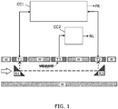
- Fig 1 shows a consumption meter embodiment not part of the invention wherein two flow transducer T1, T2, in the form of a pair of piezoelectric ultrasonic transducers, are arranged in the wall W of a flow tube in which fluid flows in the direction indicated by the large arrow to the left.
- the two transducers T1, T2 are operated by a flow measurement sub-circuit CC1 to transmit and receive ultrasonic signals via the transducers T1, T2, to be able to generate a flow rate signal indicative of the fluid flow rate, FR based on known ultrasonic transit time measurement techniques.
- reflectors R1, R2 serve to direct the ultrasonic signals (dashed arrows) along the fluid flow in the flow tube.
- the consumption meter further comprises a dedicated noise level sensor T3 configured for measuring vibro-acoustic signals in the flow tube or of the fluid therein.
- the sensor is a third separate transducer T3 located in the flow tube wall between the first and second transducers T1, T2.
- the sensor may be arranged along an unbroken flow tube wall or inside a sealable housing adapted to interface with fluid in the flow tube.
- the third transducer T3 may be a piezoelectric transducer, e.g. similar to the first and second piezoelectric transducers T1, T2.
- the third piezoelectric transducer T3 may comprise a piezoelectric element, e.g.
- the consumption meter preferably comprises a communication module (not shown) arranged to communicate data indicative of the noise level NL in addition to consumption data based on the measured flow rate FR.
- the consumption meter may correlate the measured flow rate FR and the noise level NL (and possibly other measured values) in order to be able to detect any anomaly, which may then be communicated accordingly.
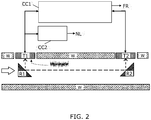
- Fig. 2 illustrates a variant of the embodiment of Fig. 1 wherein the first piezoelectric transducer T1 involved in the ultrasonic flow rate measurement is used as sensor for the acoustic signals in the flow tube or in the fluid therein.
- both the flow measurement sub-circuit CC1 and the noise measurement sub-circuit CC2 are connected to the first transducer T1.
- the first and second sub-circuits CC1, CC2 may be operated simultaneously, or it may be desirable that they are controlled so that flow rate FR and noise level NL are measured at non-overlapping operating time periods.
- the second control circuit CC2 may be arranged to spectrally filter the output from the first transducer T1.
- the embodiment according to the invention of Fig. 2 save one component, since the first transducer T1 has a dual function.
- the embodiment not part of the invention of Fig. 1 it may be possible to provide a more dedicated transducer T3 that is more sensitive to acoustic signals in the frequency range relevant for detecting anomalies.
- Fig. 3a illustrates a consumption meter embodiment not part of the invention comprising a monolithic housing and flow tube, wherein the dedicated noise level sensor is arranged at an unbroken flow tube wall together with the first and second flow transducers T1, T2 for measuring the flow rate.
- the housing and flow tube is cast as a single monolithic component 30 providing a housing 300 with an unbroken wall 310 against the flow tube (indicated with arrows).
- the wall 310 includes a first area 320 wherein a dedicated noise level sensor in terms of an ultrasonic transducer T3 is arranged.
- the wall further includes a second area 330 surrounding the first area 320.
- the thickness of the first area 320 is smaller than the thickness of the second area.
- the thickness of the first area may be equal to are greater than the thickness of the second area.
- the first area provides an acoustic window for the noise level sensor, configured for efficient pick-up of acoustic signals from the flow tube or the fluid therein.
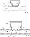
- Fig. 3c illustrates a consumption meter embodiment not part of the invention wherein the dedicated noise level sensor and the flow transducers are arranged in a housing mounted on an unbroken flow tube.
- the dedicated noise level censor such as an ultrasonic transducer T3 is mounted with a surface facing the flow tube whereby the flow tube provides a coupling surface between the noise level sensor and fluid flowing in the flow tube.
- a non-invasive arrangement is provided and the sensor is protected from the fluid in the flow tube.
- Fig. 3d illustrates a consumption meter embodiment not part of the invention wherein the dedicated noise level sensor T3 and the flow transducers T1, T2 are arranged in a sealable housing mounted on a flow tube provided with a number of openings 311.
- the sensor and the transducers are mounted in sensor inserts 301 provided in a bottom part of the housing.
- the sensor inserts 301 are protruding cavities constituted by a bottom wall 302 of the housing.
- the housing is mounted in a fluid tightly manner on the flow tube, and gaskets or other types of sealing elements (not shown) may be provided between the housing and the flow tube. When the housing is mounted, the protruding cavities extend into the openings 311 in the flow tube.
- the bottom wall of the housing provides a coupling surface between the noise level sensor and fluid flowing in the flow tube.
- the noise level sensor and the flow transducers may be arranged in one or more common sensor inserts extending into a corresponding number of openings in the flow tube.
- the housing 300 is formed as a monolithic entity and the sensor inserts 301 are formed monolithically with the housing 300 as protruding cavities constituting part of the bottom of the housing.
- the monolithic cup-shaped housing may be cast in a material such a fiber-reinforced polymer, e.g. fiber-reinforced polyphenylene sulphide (PPS).
- PPS fiber-reinforced polyphenylene sulphide
- the flow tube 310 may be either made from a polymeric material or formed in metal, such as a brass alloy or stainless steel.
- Fig. 4 illustrates a segmented ultrasonic transducer 400 to be used with the consumption meter according to the invention.
- the transducer 400 has a first transducer segment 410, which is a first electrode, and which is circular and arranged at the centre of the surface of a transducer base area.
- the transducer 400 has a second transducer segment 420, which is a second electrode, and which is annular and encircling the first transducer segment 410 on the transducer surface.
- the counter electrode 430 which is counter electrode for both of the first and second electrodes, is arranged at the lateral area of the transducer body.
- the first electrode 410 may be operated by a flow measurement sub-circuit (not shown) for flow measurements, whereas the second electrode 420 may be operated by a noise measurement sub-circuit (not shown) for noise measurements.
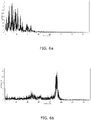
- Fig. 5a and 5b illustrate acoustic signals from a steel pipe as recorded with the consumption meter according to the invention with ( Fig. 5a ) and without ( Fig. 5b ) a leak with the pipe, respectively.
- the consumption meter of Fig. 2 was applied onto a 5.08 cm (2") steel pipe, and acoustic signals where recorded in the frequency range 0-1.54 kHz during a measurement window of 1 second.
- Fig. 6a and 6b illustrate acoustic signals from a plastic pipe as recorded with consumption meter according to the invention with ( Fig. 6a ) and without ( Fig. 6b ) a leak with the pipe, respectively.
- the consumption meter of Fig. 2 was applied onto a 2.54 cm (1") plastic (PEM) pipe, and acoustic signals where recorded in the frequency range 0-1.54 kHz during a measurement window of 1 second.
- PEM plastic
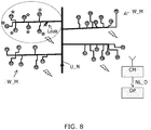
- Fig. 7 illustrates a system embodiment, where a plurality of consumption meters in terms of water meters W_M are mounted spatially distributed to measure water consumed by respective consumers connected to a water utility network U_N, which all comprise a control circuit arranged to operate a sensor for detection of acoustic signals of the flow tube, such as described in the foregoing.
- the water meters W_M all have communication means in the form of radio modules capable of transmitting data representing a noise level of the flow tube in response to the signal indicative of noise level of the flow tube. Further, the radio modules are capable of transmitting data representing a consumed amount of water from the utility network U_N.
- the individual water meter W_M preferably transmit a unique identification code, to allow billing of the individual consumers in accordance with the consumed amount of water.
- a main collector e.g. located at the utility provider, comprises a communication module CM arranged to receive said data representing the noise level of the flow tube from the plurality of water meters, and data representing a consumed amount of water, preferably along with a unique identification code to identify the individual water meter, which has transmitted the data.
- the noise level data NL_D are provided to a data processor DP, e.g. a server, arranged to monitor said data NL_D representing the noise level from the water meters in the utility network, and to determine a measure of fluid leakage in the utility network accordingly.
- a leak is indicated at a specific location on the pipe system of the utility network U_N. Stars are used to indicate water meters where higher than usual noise levels are sensed.
- the data processor may execute a leakage-monitoring algorithm that monitors the noise level data NL_D to allow early detection of leaks. E.g. by comparing observed noise level data NL_D with normally observed noise level data NL_D from the same water meters, e.g. in specific frequency bands, it will be possible to detect increased noise from a leak by water meters located near the leak, e.g. the ones indicated in Fig. 7 with stars. This allows the utility provider to locate a pipe damage and take action at an early stage after a leakage has occurred.
- the data processor DP may be arranged to determine a position of a fluid leakage in the utility network U_N in response to said noise level data NL_D and information regarding individual positions of the consumption meters in the utility network.
- identification codes allow the data processor to identify physical positions of the water meters, and by means of applying a triangulation algorithm to the noise level data NL_D and the known positions of their origins, the position of a possible leakage may be identified.
- Fig. 8 illustrates the same system as in Fig. 7 , but for a different leak position in the pipe system. Again, stars indicate water meter where an increase in noise level is sensed, i.e. water meters located in the pipe system near the leak.
- the noise level data NL_D transmitted by the water meter may have different complexity, depending on the amount of processing power in the water meters.
- the processing power may allow for a calculation of at least one statistical parameter, which can be transmitted.
- a pre-processing in the water meter may allow the individual water meters themselves to monitor for unusual noises, e.g. by comparing with registered noise levels over a long period of time.
- an alarm signal may be transmitted from the water meter in case a predetermined noise level parameter exceeds a predetermined threshold, e.g. a threshold calculated by the individual water meter in response to noise levels registered over a long period of time.
- the noise level data NL_D may comprise average noise level data, e.g. one overall value, or split up into frequency bands, e.g. 1/1 octave bands.
- the noise level data NL_D may further comprise other parameters, such as peak values and/or a level exceeded in N percent of the time, or still other values determined in response to sensed acoustic signals.
- the noise level data NL_D may be transmitted at regular time intervals, e.g. along with data representing a consumed amount of the utility, and/or the noise level data NL_D may be requested from the main collector. Especially, it may be desirable to monitor noise level data NL_D obtained at specific time intervals, e.g. during nighttime, where only few noise disturbing events on the utility network U_N are expected.
- the data processor may be arranged to receive further additional measured data from the plurality of water meters, and to take into account such additional data in determining the measure of fluid leakage in the utility network accordingly.
- additional data may comprise one or more of: data representing a flow rate, data representing a pressure, data representing a temperature, and the data representing the consumed amount of the utility.
- an increased sensitivity to leakages may be obtained, if the data processor is arranged to correlate flow rate data and/or consumed amount of the utility with the noise level data NL_D, thereby monitoring for locations with an increase in noise level as well as an increase in a consumed amount of the utility and/or measured flow rate.
- Even more data can be used, such as a decrease in pressure, which may further serve as an indicator of a leakage.
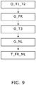
- Fig. 9 shows an embodiment according to the invention of a method of measuring a flow rate of a fluid supplied in a flow tube by means of a consumption meter.
- the method comprises operating first and second ultrasonic transducers O_T1_T2 by means of a flow measurement sub-circuit to transmit and receive ultrasonic signals through fluid flowing in a flow tube.
- generating G_FR by means of the flow measurement sub-circuit a signal indicative of flow rate of the fluid.
- Next step is operating a noise level sensor O_T3 for detection of acoustic signals of the flow tube or the fluid therein by means of a noise measurement sub-circuit.
- the flow measurement sub-circuit operates the first and second ultrasonic transducers during a first operation time period, and wherein the noise measurement sub-circuit operates the sensor for detection of acoustic signals of the flow tube during a second operation time period.
- the first and second operation time periods may be non-overlapping.
- the invention provides a consumption meter, e.g. a water or heat meter, for measuring a flow rate of a fluid supplied in a flow tube.
- First and second ultrasonic transducers are arranged at the flow tube for transmitting and receiving ultrasonic signals transmitted through the fluid and operated by a flow measurement sub-circuit for generating a signal indicative of the flow rate of the fluid.
- a noise measurement sub-circuit operates a sensor arranged at the flow tube for detection of acoustic signals of the flow tube, and being arranged to generate a signal indicative of a noise level of the flow tube accordingly.
- This sensor is constituted by one or both of the first and second ultrasonic transducers.
- the consumption meter may communicate data representative of the noise level via a communication module, along with data consumed amount of water, heat etc. Such consumer noise level measurement at the consumer site allows collection of noise level data to assist in locating fluid leakages in a fluid supply pipe system.
Landscapes
- Physics & Mathematics (AREA)
- General Physics & Mathematics (AREA)
- Chemical & Material Sciences (AREA)
- Immunology (AREA)
- Health & Medical Sciences (AREA)
- Analytical Chemistry (AREA)
- Biochemistry (AREA)
- General Health & Medical Sciences (AREA)
- Pathology (AREA)
- Life Sciences & Earth Sciences (AREA)
- Acoustics & Sound (AREA)
- Electromagnetism (AREA)
- Fluid Mechanics (AREA)
- Measuring Volume Flow (AREA)
- Engineering & Computer Science (AREA)
- Signal Processing (AREA)
- Investigating Or Analyzing Materials By The Use Of Ultrasonic Waves (AREA)
- Arrangements For Transmission Of Measured Signals (AREA)
Claims (9)
- Verbrauchsmesser, der dazu angeordnet ist, eine Durchflussrate eines Fluids zu messen, wobei der Verbrauchsmesser Folgendes umfasst:- ein Durchflussrohr mit einer Durchgangsöffnung für einen Durchlass des Fluids zwischen einem Einlass und einem Auslass,- einen ersten und einen zweiten Ultraschallwandler (T1, T2), die an einer Wand des Durchflussrohres zum Senden und Empfangen von durch das Fluid übertragenen Ultraschallsignalen angeordnet sind, wobei das Durchflussrohr eine Kopplungsfläche zwischen den Ultraschallwandlern und dem in dem Durchflussrohr fließenden Fluid bereitstellt,- eine Steuerschaltung, umfassend eine Durchflussmessungsunterschaltung (CC1), die zum Betreiben des ersten und des zweiten Ultraschallwandlers (T1, T2) angeordnet ist, und die dazu angeordnet ist, ein Signal zu erzeugen, das die Durchflussrate (FR) des Fluids aus den gesendeten und empfangenen Ultraschallsignalen, die über das Fluid übertragen werden, angibt,dadurch gekennzeichnet, dass
die Steuerschaltung ferner eine Geräuschmessungsunterschaltung (CC2) umfasst, die zum Erzeugen eines Signals angeordnet ist, das einen Geräuschpegel (NL) des Durchflussrohres oder des Fluids darin durch Betreiben zumindest eines des ersten und des zweiten Ultraschallwandlers (T1, T2), um akustische Signale des Durchflussrohres oder des Fluids zu erfassen, angibt. - Verbrauchsmesser nach Anspruch 1, wobei die Geräuschmessungsunterschaltung (CC2) zumindest einen Transimpedanzverstärker für die Umwandlung eines Stroms, der den Geräuschpegel des Durchflussrohres oder des Fluids darin angibt, in eine Spannung, die den Geräuschpegel des Durchflussrohres oder des Fluids darin angibt, umfasst.
- Verbrauchsmesser nach einem der vorhergehenden Ansprüche, wobei sowohl der erste als auch der zweite Ultraschallwandler (T1, T2) dazu betrieben werden, die akustischen Signale des Durchflussrohres oder des Fluids darin zu erkennen, wobei der erste Ultraschallwandler (T1) ein erster piezo-elektrischer Wandler ist, der ein erstes piezo-elektrisches Element mit einer ersten Polarisierungsrichtung umfasst, und wobei der zweite Ultraschallwandler (T2) ein zweiter piezo-elektrischer Wandler ist, der ein zweites piezo-elektrisches Element mit einer zweiten Polarisierungsrichtung, die der ersten Polarisierungsrichtung entgegengesetzt ist, umfasst.
- Verbrauchsmesser nach Anspruch 3, wobei die Geräuschmessungsunterschaltung (CC2) einen ersten Transimpedanzverstärker, der mit dem ersten Ultraschallwandler (T1) für die Umwandlung eines ersten Stroms, der den Geräuschpegel des Durchflussrohres oder des Fluids darin angibt, in eine erste Spannung, die den Geräuschpegel des Durchflussrohres oder des Fluids darin angibt, verbunden ist, und einen zweiten Transimpedanzverstärker, der mit dem zweiten Ultraschallwandler (T2) für die Umwandlung eines zweiten Stroms, der den Geräuschpegel des Durchflussrohres oder des Fluids darin angibt, in eine zweite Spannung, die den Geräuschpegel des Durchflussrohres oder des Fluids darin angibt, verbunden ist, umfasst, und wobei die Geräuschmessungsunterschaltung (CC2) ferner einen Differenzverstärker für die Verstärkung der Differenz zwischen der ersten und der zweiten Spannung, die den Geräuschpegel des Durchflussrohres oder des Fluids darin angeben, umfasst, um das Signal zu erzeugen, das den Geräuschpegel (NL) des Durchflussrohres oder des Fluids darin angibt.
- Verbrauchsmesser nach einem der Ansprüche 3 und 4, wobei der zumindest eine des ersten und des zweiten Ultraschallwandlers (T1, T2) ein erstes Wandlersegment und ein zweites Wandlersegment umfasst, wobei das erste Wandlersegment durch die Durchflussmessungsunterschaltung (CC1) betrieben wird, um das Signal, das die Durchflussrate des Fluids angibt, zu erzeugen, und das zweite Segment durch die Geräuschmessungsunterschaltung (CC2) zur Erkennung von akustischen Signalen des Durchflussrohres oder des Fluids darin betrieben wird.
- Verbrauchsmesser nach einem der vorhergehenden Ansprüche, wobei die Erzeugung des Signals, das den Geräuschpegel (NL) des Durchflussrohres oder des Fluids darin angibt, Bandpassfilterung des akustischen Signals umfasst, um akustische Signale außerhalb des Frequenzbereichs von 10-500 Hz zu entfernen.
- Verfahren zum Messen einer Durchflussrate eines Fluids mittels eines Verbrauchsmessers nach einem der vorhergehenden Ansprüche, wobei das Verfahren Folgendes umfasst:- Betreiben des ersten und des zweiten Ultraschallwandlers (T1, T2) durch die Durchflussmessungsunterschaltung (CC1), um Ultraschallsignale über das Fluid in dem Durchflussrohr zu senden und zu empfangen,- Erzeugen, mittels der Durchflussmessungsunterschaltung (CC1), des Signals, das die Durchflussrate (FR) des Fluids angibt,- Betreiben zumindest eines von dem ersten und dem zweiten Ultraschallwandler (T1, T2) durch die Geräuschmessungsunterschaltung (CC2), um akustische Signale des Durchflussrohres oder des Fluids darin zu erkennen, und- Erzeugen, mittels der Geräuschmessungsunterschaltung (CC2), des Signals, das den Geräuschpegel (NL) des Durchflussrohres oder des Fluids darin angibt.
- Verfahren nach Anspruch 7, wobei die Durchflussmessungsunterschaltung (CC1) während eines ersten Zeitraums betrieben wird und die Geräuschmessungsunterschaltung (CC2) während eines zweiten Zeitraums betrieben wird, und wobei der erste Zeitraum und der zweite Zeitraum keine sich überlappenden Zeiträume sind.
- System, umfassend eine Vielzahl von Verbrauchsmessern nach einem der vorhergehenden Ansprüche 1-6, wobei die Vielzahl von Verbrauchsmessern räumlich verteilt an Verbrauchsstellen in einem Versorgungsnetz angeordnet ist, wobei jeder aus der Vielzahl von Verbrauchsmessern ferner Kommunikationsmittel umfasst, die dazu angeordnet sind, Daten, die den Geräuschpegel des Durchflussrohres oder des Fluids darin darstellen, zu übertragen, und wobei das System einen Hauptsammler, der dazu angeordnet ist, die Daten von der Vielzahl von Verbrauchsmessern, die den Geräuschpegel des Durchflussrohres oder des Fluids darin darstellen, zu empfangen, und einen Datenprozessor, der dazu angeordnet ist, die Daten von der Vielzahl von Verbrauchsmessern, die den Geräuschpegel des Durchflussrohres oder des Fluids darin darstellen, zu verarbeiten und einen Messwert einer Position einer Fluidleckage in dem Versorgungsnetz als Reaktion auf die Daten und Informationen hinsichtlich einzelner Positionen eines jeden aus der Vielzahl von Verbrauchsmessern in dem Versorgungsnetz zu bestimmen, umfasst.
Priority Applications (7)
| Application Number | Priority Date | Filing Date | Title |
|---|---|---|---|
| EP21152897.1A EP3828512B1 (de) | 2015-07-03 | 2016-07-04 | Flüssigkeitsverbrauchsmesser mit geräuschsensor |
| EP21152894.8A EP3828511B1 (de) | 2015-07-03 | 2016-07-04 | Flüssigkeitsverbrauchsmesser mit geräuschsensor |
| EP21152899.7A EP3828513B1 (de) | 2015-07-03 | 2016-07-04 | Flüssigkeitsverbrauchsmesser mit geräuschsensor |
| PL16733998T PL3317618T3 (pl) | 2015-07-03 | 2016-07-04 | Licznik zużycia płynu wyposażony w czujnik szumu |
| EP21152904.5A EP3828514B1 (de) | 2015-07-03 | 2016-07-04 | Flüssigkeitsverbrauchsmesser mit geräuschsensor |
| EP24154341.2A EP4336179A3 (de) | 2015-07-03 | 2016-07-04 | Flüssigkeitsverbrauchsmesser mit geräuschsensor |
| EP21152903.7A EP3845867B1 (de) | 2015-07-03 | 2016-07-04 | Flüssigkeitsverbrauchszähler mit geräuschsensor und verfahren zur messung eines flüssigkeitsdurchsatzes mittels des flüssigkeitsverbrauchsmessers mit geräuschsensor |
Applications Claiming Priority (4)
| Application Number | Priority Date | Filing Date | Title |
|---|---|---|---|
| EP15175269.8A EP3112820A1 (de) | 2015-07-03 | 2015-07-03 | Flüssigkeitsverbrauchsmesser mit geräuschsensor |
| EP15175271.4A EP3112823A1 (de) | 2015-07-03 | 2015-07-03 | System zur überwachung eines versorgungsnetzwerks |
| EP15175270.6A EP3112856A1 (de) | 2015-07-03 | 2015-07-03 | Trübungssensor auf basis von ultraschallmessungen |
| PCT/EP2016/065697 WO2017005687A1 (en) | 2015-07-03 | 2016-07-04 | Fluid consumption meter with noise sensor |
Related Child Applications (11)
| Application Number | Title | Priority Date | Filing Date |
|---|---|---|---|
| EP21152897.1A Division-Into EP3828512B1 (de) | 2015-07-03 | 2016-07-04 | Flüssigkeitsverbrauchsmesser mit geräuschsensor |
| EP21152897.1A Division EP3828512B1 (de) | 2015-07-03 | 2016-07-04 | Flüssigkeitsverbrauchsmesser mit geräuschsensor |
| EP21152904.5A Division EP3828514B1 (de) | 2015-07-03 | 2016-07-04 | Flüssigkeitsverbrauchsmesser mit geräuschsensor |
| EP21152904.5A Division-Into EP3828514B1 (de) | 2015-07-03 | 2016-07-04 | Flüssigkeitsverbrauchsmesser mit geräuschsensor |
| EP24154341.2A Division EP4336179A3 (de) | 2015-07-03 | 2016-07-04 | Flüssigkeitsverbrauchsmesser mit geräuschsensor |
| EP21152894.8A Division EP3828511B1 (de) | 2015-07-03 | 2016-07-04 | Flüssigkeitsverbrauchsmesser mit geräuschsensor |
| EP21152894.8A Division-Into EP3828511B1 (de) | 2015-07-03 | 2016-07-04 | Flüssigkeitsverbrauchsmesser mit geräuschsensor |
| EP21152899.7A Division EP3828513B1 (de) | 2015-07-03 | 2016-07-04 | Flüssigkeitsverbrauchsmesser mit geräuschsensor |
| EP21152899.7A Division-Into EP3828513B1 (de) | 2015-07-03 | 2016-07-04 | Flüssigkeitsverbrauchsmesser mit geräuschsensor |
| EP21152903.7A Division-Into EP3845867B1 (de) | 2015-07-03 | 2016-07-04 | Flüssigkeitsverbrauchszähler mit geräuschsensor und verfahren zur messung eines flüssigkeitsdurchsatzes mittels des flüssigkeitsverbrauchsmessers mit geräuschsensor |
| EP21152903.7A Division EP3845867B1 (de) | 2015-07-03 | 2016-07-04 | Flüssigkeitsverbrauchszähler mit geräuschsensor und verfahren zur messung eines flüssigkeitsdurchsatzes mittels des flüssigkeitsverbrauchsmessers mit geräuschsensor |
Publications (2)
| Publication Number | Publication Date |
|---|---|
| EP3317618A1 EP3317618A1 (de) | 2018-05-09 |
| EP3317618B1 true EP3317618B1 (de) | 2021-09-01 |
Family
ID=56296844
Family Applications (8)
| Application Number | Title | Priority Date | Filing Date |
|---|---|---|---|
| EP16736786.1A Active EP3317658B1 (de) | 2015-07-03 | 2016-07-01 | Trübungssensor auf basis von ultraschallmessungen |
| EP21152903.7A Active EP3845867B1 (de) | 2015-07-03 | 2016-07-04 | Flüssigkeitsverbrauchszähler mit geräuschsensor und verfahren zur messung eines flüssigkeitsdurchsatzes mittels des flüssigkeitsverbrauchsmessers mit geräuschsensor |
| EP24154341.2A Pending EP4336179A3 (de) | 2015-07-03 | 2016-07-04 | Flüssigkeitsverbrauchsmesser mit geräuschsensor |
| EP21152899.7A Active EP3828513B1 (de) | 2015-07-03 | 2016-07-04 | Flüssigkeitsverbrauchsmesser mit geräuschsensor |
| EP21152894.8A Active EP3828511B1 (de) | 2015-07-03 | 2016-07-04 | Flüssigkeitsverbrauchsmesser mit geräuschsensor |
| EP16733998.5A Active EP3317618B1 (de) | 2015-07-03 | 2016-07-04 | Flüssigkeitsverbrauchsmesser mit geräuschsensor |
| EP21152904.5A Active EP3828514B1 (de) | 2015-07-03 | 2016-07-04 | Flüssigkeitsverbrauchsmesser mit geräuschsensor |
| EP21152897.1A Active EP3828512B1 (de) | 2015-07-03 | 2016-07-04 | Flüssigkeitsverbrauchsmesser mit geräuschsensor |
Family Applications Before (5)
| Application Number | Title | Priority Date | Filing Date |
|---|---|---|---|
| EP16736786.1A Active EP3317658B1 (de) | 2015-07-03 | 2016-07-01 | Trübungssensor auf basis von ultraschallmessungen |
| EP21152903.7A Active EP3845867B1 (de) | 2015-07-03 | 2016-07-04 | Flüssigkeitsverbrauchszähler mit geräuschsensor und verfahren zur messung eines flüssigkeitsdurchsatzes mittels des flüssigkeitsverbrauchsmessers mit geräuschsensor |
| EP24154341.2A Pending EP4336179A3 (de) | 2015-07-03 | 2016-07-04 | Flüssigkeitsverbrauchsmesser mit geräuschsensor |
| EP21152899.7A Active EP3828513B1 (de) | 2015-07-03 | 2016-07-04 | Flüssigkeitsverbrauchsmesser mit geräuschsensor |
| EP21152894.8A Active EP3828511B1 (de) | 2015-07-03 | 2016-07-04 | Flüssigkeitsverbrauchsmesser mit geräuschsensor |
Family Applications After (2)
| Application Number | Title | Priority Date | Filing Date |
|---|---|---|---|
| EP21152904.5A Active EP3828514B1 (de) | 2015-07-03 | 2016-07-04 | Flüssigkeitsverbrauchsmesser mit geräuschsensor |
| EP21152897.1A Active EP3828512B1 (de) | 2015-07-03 | 2016-07-04 | Flüssigkeitsverbrauchsmesser mit geräuschsensor |
Country Status (8)
| Country | Link |
|---|---|
| US (5) | US10379084B2 (de) |
| EP (8) | EP3317658B1 (de) |
| CN (5) | CN107923880B (de) |
| DK (2) | DK3317658T3 (de) |
| ES (1) | ES2898614T3 (de) |
| LT (2) | LT3317658T (de) |
| PL (2) | PL3317658T3 (de) |
| WO (3) | WO2017005269A1 (de) |
Cited By (1)
| Publication number | Priority date | Publication date | Assignee | Title |
|---|---|---|---|---|
| EP4177575B1 (de) | 2021-11-09 | 2024-09-25 | Diehl Metering GmbH | Druckermittlung in einem ultraschall-fluidzähler mittels piezokeramischem ultraschall-wandler |
Families Citing this family (41)
| Publication number | Priority date | Publication date | Assignee | Title |
|---|---|---|---|---|
| DK3317658T3 (da) * | 2015-07-03 | 2020-11-30 | Kamstrup As | Turbiditetssensor baseret på ultralydsmålinger |
| EP3299774A1 (de) * | 2016-09-21 | 2018-03-28 | Kamstrup A/S | Ultraschalldurchflussmesser und verfahren mit verwendung partieller durchflussmessungen |
| CA3040190C (en) * | 2016-10-13 | 2025-11-25 | South East Water Corporation | VIBRATION SENSOR INTENDED FOR FLUID LEAK DETECTION |
| US20180217102A1 (en) * | 2017-01-30 | 2018-08-02 | Jared Negussie Wolde Michael | Ultrasonic flow meter configured to detect impurities in a fluid |
| EP3367072B1 (de) * | 2017-02-24 | 2019-01-02 | SICK Engineering GmbH | Strömungsmessung mit ultraschall |
| DE102017011201B4 (de) | 2017-12-05 | 2023-01-26 | Diehl Metering Gmbh | Verfahren zur Betriebsüberwachung eines Fluidzählers sowie Fluidzähler |
| CN109187739B (zh) * | 2018-09-12 | 2021-12-07 | 浙江理工大学 | 基于超声波衰减实现混合液体浊度测量的系统及方法 |
| CN109404745B (zh) * | 2018-12-18 | 2024-04-05 | 杨启敖 | 带超声波的漏水保护器 |
| CN109404744B (zh) * | 2018-12-18 | 2024-01-16 | 杨启敖 | 带前置过滤的漏水保护装置 |
| US11885656B2 (en) * | 2019-03-14 | 2024-01-30 | Omron Corporation | Flow-rate measuring apparatus capable of accurately measuring flow rate of fluid with reflecting viscosity of fluid |
| CN110057908B (zh) * | 2019-04-10 | 2024-07-12 | 宁波水表(集团)股份有限公司 | 基于超声波的供水管网浑浊度在线测量装置 |
| CN109974800A (zh) * | 2019-04-11 | 2019-07-05 | 无锡洋湃科技有限公司 | 基于谐振和差压测量的湿气流量计 |
| DE102019206997B4 (de) * | 2019-05-14 | 2021-11-11 | Fraunhofer-Gesellschaft zur Förderung der angewandten Forschung e.V. | System zur zerstörungsfreien Prüfung von Bauteilen |
| JP7356818B2 (ja) * | 2019-05-23 | 2023-10-05 | 愛知時計電機株式会社 | 異物混入位置の推定方法及び流量計 |
| FR3099827B1 (fr) * | 2019-08-09 | 2021-10-15 | Sagemcom Energy & Telecom Sas | Procédé de surveillance d’un ensemble de compteurs |
| DE102019127409A1 (de) * | 2019-10-11 | 2021-04-15 | Rosen Swiss Ag | Verfahren zur Leckerkennung |
| CN112903046B (zh) | 2019-11-19 | 2025-06-13 | 卡姆鲁普股份有限公司 | 模块化超声耗量表 |
| US12535378B2 (en) | 2019-11-26 | 2026-01-27 | Kamstrup A/S | Fluid consumption meter and leak detection system |
| CN110726698B (zh) * | 2019-11-28 | 2022-02-22 | 浙江农林大学 | 一种城市河道生态智能监测母站的浊度监测方法 |
| DK180728B1 (en) * | 2020-03-10 | 2022-02-08 | Kamstrup As | System and method for acoustic leak detection |
| WO2021182696A1 (ko) * | 2020-03-12 | 2021-09-16 | 주식회사 위플랫 | 누수음 탐지 시스템 |
| FR3109214B1 (fr) * | 2020-04-09 | 2022-09-02 | Sagemcom Energy & Telecom Sas | Procédé de détection et de localisation d’une fuite de fluide |
| WO2022035811A1 (en) * | 2020-08-13 | 2022-02-17 | Alarm.Com Incorporated | Periodic water leak detection |
| CN114441632A (zh) * | 2020-10-30 | 2022-05-06 | 上海科闫系统科技有限公司 | 水处理系统阻垢效果在线检测装置及方法 |
| EP4019908B1 (de) | 2020-12-28 | 2024-01-17 | Kamstrup A/S | Flüssigkeitsverbrauchszähler und verfahren zur schalldetektion in einem rohrleitungssystem |
| CN112857490A (zh) * | 2021-01-15 | 2021-05-28 | 深圳市宏电技术股份有限公司 | 一种流量计算装置和计算方法 |
| EP4071454B1 (de) * | 2021-04-08 | 2025-01-15 | Kamstrup A/S | Verfahren zur ortung eines lecks in einem wasserversorgungsnetz |
| EP4538668A3 (de) * | 2021-04-30 | 2025-07-02 | Kamstrup A/S | Verfahren zur akustischen lecksuche in einem fernwärmeleitungsnetz |
| EP4095503A1 (de) | 2021-05-26 | 2022-11-30 | Kamstrup A/S | Zeitsynchronisiertes leckdetektionssystem |
| EP4399439A1 (de) | 2021-09-06 | 2024-07-17 | Kamstrup A/S | System und verfahren zur akustischen leckdetektion in einem versorgungsverteilungssystem |
| CN114427895A (zh) * | 2021-12-17 | 2022-05-03 | 宁波职业技术学院 | 一种液体流量的检测方法与系统 |
| CN114485820A (zh) * | 2022-01-12 | 2022-05-13 | 肇庆奥迪威传感科技有限公司 | 流量传感器 |
| JP7775719B2 (ja) * | 2022-01-20 | 2025-11-26 | セイコーエプソン株式会社 | 流体デバイスおよび流体デバイスの制御方法 |
| KR102881137B1 (ko) * | 2022-01-20 | 2025-11-04 | 양강석 | 초음파 센서를 이용한 유수의 탁도 측정 장치 |
| US11573098B1 (en) * | 2022-06-08 | 2023-02-07 | King Fahd University Of Petroleum And Minerals | Method and system to detect non-technical losses in an electrical power system |
| DE102022122181A1 (de) * | 2022-09-01 | 2024-03-07 | Krohne Ag | Verfahren zum Betreiben eines Ultraschalldurchflussmessgeräts und Ultraschalldurchflussmessgerät |
| IT202300014229A1 (it) * | 2023-07-07 | 2025-01-07 | Elettrotecnica Rold Srl | Metodo ed apparato per il monitoraggio e il controllo della qualita’ dell’acqua utilizzata in elettrodomestici |
| CN116608917B (zh) | 2023-07-19 | 2023-09-22 | 成都秦川物联网科技股份有限公司 | 气体超声波计量仪表计量抗扰方法与智慧燃气物联网系统 |
| EP4513149A1 (de) * | 2023-08-23 | 2025-02-26 | Kamstrup A/S | Verbrauchszähler mit druckübergangserkennung |
| CN119023163B (zh) * | 2024-10-28 | 2024-12-20 | 艾肯(江苏)工业技术有限公司 | 一种基于超声波的阀门泄漏微流量检测装置 |
| CN119880825B (zh) * | 2025-03-19 | 2025-07-29 | 安徽恒宇环保设备制造股份有限公司 | 一种用于地表水的水质监测方法及系统 |
Family Cites Families (73)
| Publication number | Priority date | Publication date | Assignee | Title |
|---|---|---|---|---|
| US3109112A (en) * | 1962-03-13 | 1963-10-29 | Robert A Lester | Double frequency transducer |
| GB1121824A (en) * | 1965-12-14 | 1968-07-31 | Exxon Research Engineering Co | Pipeline leak detector |
| NL6600966A (de) * | 1965-12-22 | 1967-07-27 | ||
| US3849002A (en) * | 1973-05-11 | 1974-11-19 | Hach Chemical Co | Method and apparatus for eliminating air during fluid turbidity measurement |
| US3906791A (en) * | 1973-10-01 | 1975-09-23 | Panametrics | Area averaging ultrasonic flowmeters |
| US4527420A (en) * | 1982-06-11 | 1985-07-09 | Micro Pure Systems, Inc. | Ultrasonic particulate sensing |
| US6248077B1 (en) | 1982-07-19 | 2001-06-19 | Edwards Lifesciences Corp. | System for sensing a characteristic of fluid flowing to or from a body |
| US4476877A (en) | 1982-08-16 | 1984-10-16 | Gould Inc. | Fluid temperature sensor |
| US4542644A (en) * | 1983-09-26 | 1985-09-24 | The United States Of America As Represented By The United States Department Of Energy | Void/particulate detector |
| US4740709A (en) * | 1986-04-10 | 1988-04-26 | The United States Of America As Represented By The Department Of Health And Human Services | Method of sensing fluid properties independent of bubble concentrations |
| US5151085A (en) * | 1989-04-28 | 1992-09-29 | Olympus Optical Co., Ltd. | Apparatus for generating ultrasonic oscillation |
| JP2878804B2 (ja) * | 1989-09-19 | 1999-04-05 | 東京瓦斯株式会社 | 配管の異常監視装置 |
| NZ243294A (en) * | 1991-06-25 | 1995-04-27 | Commw Scient Ind Res Org | Time of flight of acoustic wave packets through fluid: reduction of higher order acoustic mode effects |
| JPH05209822A (ja) * | 1992-01-30 | 1993-08-20 | Hitachi Ltd | 粒子計数装置 |
| EP0690974A4 (de) | 1993-03-09 | 1996-05-22 | Commw Scient Ind Res Org | Flüssigkeitsmesserkonstruktion |
| US5710377A (en) * | 1995-10-17 | 1998-01-20 | The United States Of America As Represented By The Administrator Of The National Aeronautics And Space Administration | Ultrasonic leak detection system |
| US5688406A (en) * | 1996-02-28 | 1997-11-18 | The United States Of America As Represented By The Secretary Of The Navy | Method and apparatus for separating particulate from a flowing fluid |
| DE19713526A1 (de) | 1997-04-01 | 1998-10-08 | Elster Produktion Gmbh | Vorrichtung zur Ultraschall-Durchflußmessung |
| US5969237A (en) * | 1997-10-09 | 1999-10-19 | Baker Hughes Incorporated | Measurement and control of asphaltene agglomeration in hydrocarbon Liquids |
| FI111433B (fi) * | 1998-01-29 | 2003-07-15 | Nokia Corp | Menetelmä tiedonsiirron salaamiseksi ja solukkoradiojärjestelmä |
| IT1311771B1 (it) * | 1999-02-24 | 2002-03-19 | Giorgio Bergamini | Misuratore perfezionato della portata di gas con gli ultrasuoni basato su specchi parabolici. |
| KR100487690B1 (ko) | 1999-06-24 | 2005-05-06 | 마쯔시다덴기산교 가부시키가이샤 | 유량계 |
| PL196979B1 (pl) * | 1999-10-26 | 2008-02-29 | Peter Martinek | Sposób przeprowadzenia pomiarów w systemach wodociągowych i sonda pomiarowa |
| CN1283780A (zh) * | 2000-08-28 | 2001-02-14 | 浙江省苍南众星实业有限公司 | 管道内流体流量的测量方法及其声波流量计 |
| JP2002116073A (ja) * | 2000-10-10 | 2002-04-19 | Osaka Gas Co Ltd | 流量測定方法 |
| DE10051534A1 (de) | 2000-10-18 | 2002-04-25 | Sensorentechnologie Gettorf Gm | Sensorsystem und Verfahren |
| CN1708674A (zh) * | 2002-04-24 | 2005-12-14 | 塞德拉公司 | 测量在管道中流动的流体中具有悬浮的固体微粒的混合物的参数的装置和方法 |
| DE10227918A1 (de) * | 2002-06-21 | 2004-01-15 | Bühler AG | Verfahren zum Bestimmen rheologischer Parameter eines Fluids |
| CN1184483C (zh) * | 2002-12-24 | 2005-01-12 | 上海大学 | 集成式浆体浓度流量在线测量方法和系统 |
| US7096719B2 (en) * | 2003-01-13 | 2006-08-29 | Cidra Corporation | Apparatus for measuring parameters of a flowing multiphase mixture |
| CN100504311C (zh) * | 2003-01-13 | 2009-06-24 | 塞德拉公司 | 使用超声波传感器阵列确定管道内的流体速度的设备和方法 |
| JP4275990B2 (ja) | 2003-05-20 | 2009-06-10 | 株式会社キーエンス | 流量センサ |
| EP1522839B1 (de) * | 2003-10-08 | 2006-06-07 | INNOVA AirTech Instruments A/S | Ultraschallgasleckdetektor mit einer Vorrichtung zur Detektoruntersuchung |
| NO318971B1 (no) * | 2003-10-30 | 2005-05-30 | Statoil Asa | Anordning og system for tilstandskontroll av en rorledning ved bruk av ultralyd |
| US6983208B2 (en) * | 2003-11-24 | 2006-01-03 | Mgd Technologies, Inc. | Method and apparatus for combined measurements of concentration, distribution and flow velocity of suspended solids |
| US7617738B2 (en) * | 2004-06-01 | 2009-11-17 | Avance Techne Accent Corp. | Method and apparatus for measuring flow rate of fluid |
| DE102004057695B4 (de) * | 2004-11-30 | 2009-12-24 | Abb Ag | Magnetisch induktiver Durchflussmesser mit einem Messrohr aus Kunststoff |
| CN100541170C (zh) * | 2004-12-30 | 2009-09-16 | 中国科学院海洋研究所 | 海洋声学浊度传感器 |
| CN1332183C (zh) * | 2005-08-10 | 2007-08-15 | 陈宇 | 流体的流量检测装置 |
| DE102006027422B4 (de) * | 2006-06-13 | 2014-02-06 | Continental Automotive Gmbh | Verfahren und Vorrichtung zum Überwachen eines Abgasturboladers |
| WO2008053193A1 (en) | 2006-10-31 | 2008-05-08 | Imi Vision Limited | Ultrasonic flow-rate measurement device and system |
| US8305231B2 (en) * | 2007-03-23 | 2012-11-06 | Panasonic Corporation | Gas appliance monitoring apparatus |
| US20100268489A1 (en) * | 2007-10-10 | 2010-10-21 | Terje Lennart Lie | Method and system for registering and measuring leaks and flows |
| CN201107066Y (zh) * | 2007-11-02 | 2008-08-27 | 重庆钢铁(集团)有限责任公司 | 超声波流量计用耐高温换能器 |
| EP2083251A1 (de) | 2007-12-13 | 2009-07-29 | Kamstrup A/S | Verbrauchsmesser mit mindestens zwei Gehäuseteilen |
| DE102008019989B4 (de) | 2008-04-21 | 2010-07-01 | Mib Gmbh Messtechnik Und Industrieberatung | Ultraschall-Messanordnung |
| CN201222055Y (zh) * | 2008-05-27 | 2009-04-15 | 成都敏博科技有限公司 | 超声波气体浓度测量装置 |
| US8085156B2 (en) * | 2009-04-08 | 2011-12-27 | Rosemount Inc. | RF cavity-based process fluid sensor |
| EP2336732A1 (de) | 2009-12-15 | 2011-06-22 | Kamstrup A/S | Verbrauchsmesser mit Durchflussteil und Gehäuse aus monolithischer Polymerstruktur |
| US8665101B2 (en) * | 2009-11-16 | 2014-03-04 | Aquarius Spectrum Ltd. | System method and device for leak detection and localization in a pipe network |
| US7920983B1 (en) * | 2010-03-04 | 2011-04-05 | TaKaDu Ltd. | System and method for monitoring resources in a water utility network |
| DE102010029283A1 (de) * | 2010-05-25 | 2011-12-01 | Robert Bosch Gmbh | Ultraschallwandler zum Einsatz in einem fluiden Medium |
| US20110298635A1 (en) * | 2010-06-04 | 2011-12-08 | Bernie Yip | Self dynamo smart flow utility meter and system for flow utility real-time flow usage monitoring and control, self error and leakages monitoring |
| CN103002799B (zh) * | 2010-06-24 | 2017-02-08 | 日本先锋公司 | 光检测设备和流体测量设备 |
| CN103189719B (zh) * | 2010-09-03 | 2016-03-16 | 洛斯阿拉莫斯国家安全股份有限公司 | 用于非侵入式确定管道内部的流体的声学特性的方法 |
| EP2612143A4 (de) * | 2010-09-03 | 2017-01-18 | Los Alamos National Security LLC | Vorrichtung und verfahren für nichtinvasive partikeldetektion mithilfe einer dopplerspektroskopie |
| US7942066B1 (en) * | 2010-09-22 | 2011-05-17 | Florida Turbine Technologies, Inc. | Non-intrusive two-phase flow measurement system |
| AU2014202604B2 (en) * | 2011-02-09 | 2015-08-27 | South East Water Corporation | Wirelessly networked fluid monitoring method, system and apparatus |
| EP2684011A4 (de) | 2011-03-07 | 2015-09-30 | Los Alamos Nat Security Llc | Vorrichtung und verfahren zur akustischen überwachung der qualität und strömung eines dampfs |
| US10989635B2 (en) * | 2011-03-18 | 2021-04-27 | Cidra Corporate Services, Inc. | Acoustic standing wave particle size or distribution detection |
| GB2491804B (en) * | 2011-05-11 | 2018-01-17 | Syrinix Ltd | Pipeline fault detection system and monitor unit |
| EP2758753B1 (de) * | 2011-09-23 | 2016-02-24 | Kamstrup A/S | Durchflussmesser mit vorstehenden wandler |
| KR101142897B1 (ko) * | 2011-10-06 | 2012-05-10 | 웨스글로벌 주식회사 | 초음파 유량 및 농도 공용 측정 시스템 |
| EP2581715A1 (de) | 2011-10-13 | 2013-04-17 | Miitors ApS | Ultraschalldurchflussmesser |
| WO2013059360A1 (en) | 2011-10-17 | 2013-04-25 | Prodyne Corporation | Ultrasonic measurement of particle size distribution |
| US10508937B2 (en) * | 2012-04-12 | 2019-12-17 | Texas Instruments Incorporated | Ultrasonic flow meter |
| DE102012012252C5 (de) * | 2012-06-22 | 2025-03-27 | Krohne Ag | System zur Durchflussmessung |
| SG11201503041SA (en) * | 2012-10-26 | 2015-05-28 | Mueller Int Llc | Detecting leaks in a fluid distribution system |
| US9503133B2 (en) * | 2012-12-03 | 2016-11-22 | Dockon Ag | Low noise detection system using log detector amplifier |
| CN104838241B (zh) * | 2012-12-04 | 2019-05-28 | 斯蒂芬.J.霍恩 | 流体流动检测和分析设备及系统 |
| CN103292160B (zh) * | 2013-06-27 | 2015-11-18 | 陕西师范大学 | 管道泄漏的超声波检测装置及方法 |
| US9928724B2 (en) * | 2015-05-13 | 2018-03-27 | Rachio, Inc. | Flow characteristic detection and automatic flow shutoff |
| DK3317658T3 (da) * | 2015-07-03 | 2020-11-30 | Kamstrup As | Turbiditetssensor baseret på ultralydsmålinger |
-
2016
- 2016-07-01 DK DK16736786.1T patent/DK3317658T3/da active
- 2016-07-01 EP EP16736786.1A patent/EP3317658B1/de active Active
- 2016-07-01 LT LTEP16736786.1T patent/LT3317658T/lt unknown
- 2016-07-01 US US15/741,560 patent/US10379084B2/en active Active
- 2016-07-01 PL PL16736786T patent/PL3317658T3/pl unknown
- 2016-07-01 CN CN201680039528.7A patent/CN107923880B/zh active Active
- 2016-07-01 WO PCT/DK2016/050236 patent/WO2017005269A1/en not_active Ceased
- 2016-07-01 WO PCT/DK2016/050235 patent/WO2017005268A1/en not_active Ceased
- 2016-07-04 EP EP21152903.7A patent/EP3845867B1/de active Active
- 2016-07-04 EP EP24154341.2A patent/EP4336179A3/de active Pending
- 2016-07-04 LT LTEPPCT/EP2016/065697T patent/LT3317618T/lt unknown
- 2016-07-04 EP EP21152899.7A patent/EP3828513B1/de active Active
- 2016-07-04 CN CN202110043916.5A patent/CN112665667B/zh active Active
- 2016-07-04 EP EP21152894.8A patent/EP3828511B1/de active Active
- 2016-07-04 WO PCT/EP2016/065697 patent/WO2017005687A1/en not_active Ceased
- 2016-07-04 EP EP16733998.5A patent/EP3317618B1/de active Active
- 2016-07-04 ES ES16733998T patent/ES2898614T3/es active Active
- 2016-07-04 EP EP21152904.5A patent/EP3828514B1/de active Active
- 2016-07-04 PL PL16733998T patent/PL3317618T3/pl unknown
- 2016-07-04 CN CN202110043930.5A patent/CN112665668B/zh active Active
- 2016-07-04 US US15/741,567 patent/US10921288B2/en active Active
- 2016-07-04 CN CN202110051512.0A patent/CN112665669B/zh active Active
- 2016-07-04 EP EP21152897.1A patent/EP3828512B1/de active Active
- 2016-07-04 CN CN201680039499.4A patent/CN107709938B/zh active Active
- 2016-07-04 DK DK16733998.5T patent/DK3317618T3/da active
-
2019
- 2019-05-31 US US16/427,836 patent/US11391699B2/en active Active
-
2020
- 2020-09-23 US US17/029,153 patent/US11852609B2/en active Active
-
2023
- 2023-11-15 US US18/509,492 patent/US12235241B2/en active Active
Cited By (1)
| Publication number | Priority date | Publication date | Assignee | Title |
|---|---|---|---|---|
| EP4177575B1 (de) | 2021-11-09 | 2024-09-25 | Diehl Metering GmbH | Druckermittlung in einem ultraschall-fluidzähler mittels piezokeramischem ultraschall-wandler |
Also Published As
Similar Documents
| Publication | Publication Date | Title |
|---|---|---|
| US12235241B2 (en) | Fluid consumption meter with noise sensor | |
| EP3112820A1 (de) | Flüssigkeitsverbrauchsmesser mit geräuschsensor | |
| AU2021200703B2 (en) | Apparatus and method for the detection and monitoring of the condition of pipeline components | |
| CA2961798C (en) | Ultrasonic flow meter leak detection system and method | |
| US20140174186A1 (en) | System method and device for leak detection and localization in a pipe network | |
| Islam et al. | Leak detection and location pinpointing in water pipeline systems using a wireless sensor network | |
| KR102015990B1 (ko) | 진동감지를 이용한 누수 검출수단이 구비된 원격검침용 유량계 | |
| RU2462656C2 (ru) | Комбинированная гидроакустическая система обнаружения утечек нефтепродуктопровода | |
| EP4071454B1 (de) | Verfahren zur ortung eines lecks in einem wasserversorgungsnetz |
Legal Events
| Date | Code | Title | Description |
|---|---|---|---|
| STAA | Information on the status of an ep patent application or granted ep patent |
Free format text: STATUS: THE INTERNATIONAL PUBLICATION HAS BEEN MADE |
|
| PUAI | Public reference made under article 153(3) epc to a published international application that has entered the european phase |
Free format text: ORIGINAL CODE: 0009012 |
|
| STAA | Information on the status of an ep patent application or granted ep patent |
Free format text: STATUS: REQUEST FOR EXAMINATION WAS MADE |
|
| 17P | Request for examination filed |
Effective date: 20180201 |
|
| AK | Designated contracting states |
Kind code of ref document: A1 Designated state(s): AL AT BE BG CH CY CZ DE DK EE ES FI FR GB GR HR HU IE IS IT LI LT LU LV MC MK MT NL NO PL PT RO RS SE SI SK SM TR |
|
| AX | Request for extension of the european patent |
Extension state: BA ME |
|
| DAV | Request for validation of the european patent (deleted) | ||
| DAX | Request for extension of the european patent (deleted) | ||
| RIC1 | Information provided on ipc code assigned before grant |
Ipc: G01N 29/50 20060101ALI20200630BHEP Ipc: G01D 4/00 20060101ALI20200630BHEP Ipc: G01F 1/66 20060101AFI20200630BHEP Ipc: G01N 29/22 20060101ALI20200630BHEP Ipc: G01N 29/032 20060101ALI20200630BHEP Ipc: G01M 3/28 20060101ALI20200630BHEP Ipc: G01M 3/24 20060101ALI20200630BHEP |
|
| GRAP | Despatch of communication of intention to grant a patent |
Free format text: ORIGINAL CODE: EPIDOSNIGR1 |
|
| STAA | Information on the status of an ep patent application or granted ep patent |
Free format text: STATUS: GRANT OF PATENT IS INTENDED |
|
| INTG | Intention to grant announced |
Effective date: 20200903 |
|
| RIN1 | Information on inventor provided before grant (corrected) |
Inventor name: PETERSEN, MARTIN CHRISTIAN HOEJ Inventor name: NIELSEN, SOEREN TOENNES Inventor name: LAURSEN, PETER SCHMIDT Inventor name: SOERENSEN, JENS LYKKE Inventor name: KRISTENSEN, RENE GAJDA |
|
| GRAS | Grant fee paid |
Free format text: ORIGINAL CODE: EPIDOSNIGR3 |
|
| GRAJ | Information related to disapproval of communication of intention to grant by the applicant or resumption of examination proceedings by the epo deleted |
Free format text: ORIGINAL CODE: EPIDOSDIGR1 |
|
| GRAL | Information related to payment of fee for publishing/printing deleted |
Free format text: ORIGINAL CODE: EPIDOSDIGR3 |
|
| STAA | Information on the status of an ep patent application or granted ep patent |
Free format text: STATUS: REQUEST FOR EXAMINATION WAS MADE |
|
| INTC | Intention to grant announced (deleted) | ||
| GRAP | Despatch of communication of intention to grant a patent |
Free format text: ORIGINAL CODE: EPIDOSNIGR1 |
|
| STAA | Information on the status of an ep patent application or granted ep patent |
Free format text: STATUS: GRANT OF PATENT IS INTENDED |
|
| INTG | Intention to grant announced |
Effective date: 20210318 |
|
| GRAA | (expected) grant |
Free format text: ORIGINAL CODE: 0009210 |
|
| STAA | Information on the status of an ep patent application or granted ep patent |
Free format text: STATUS: THE PATENT HAS BEEN GRANTED |
|
| AK | Designated contracting states |
Kind code of ref document: B1 Designated state(s): AL AT BE BG CH CY CZ DE DK EE ES FI FR GB GR HR HU IE IS IT LI LT LU LV MC MK MT NL NO PL PT RO RS SE SI SK SM TR |
|
| REG | Reference to a national code |
Ref country code: GB Ref legal event code: FG4D |
|
| REG | Reference to a national code |
Ref country code: CH Ref legal event code: EP Ref country code: AT Ref legal event code: REF Ref document number: 1426685 Country of ref document: AT Kind code of ref document: T Effective date: 20210915 |
|
| REG | Reference to a national code |
Ref country code: DE Ref legal event code: R096 Ref document number: 602016063062 Country of ref document: DE |
|
| REG | Reference to a national code |
Ref country code: IE Ref legal event code: FG4D |
|
| REG | Reference to a national code |
Ref country code: FI Ref legal event code: FGE |
|
| REG | Reference to a national code |
Ref country code: DK Ref legal event code: T3 Effective date: 20211130 |
|
| REG | Reference to a national code |
Ref country code: SE Ref legal event code: TRGR |
|
| REG | Reference to a national code |
Ref country code: NL Ref legal event code: FP |
|
| PG25 | Lapsed in a contracting state [announced via postgrant information from national office to epo] |
Ref country code: BG Free format text: LAPSE BECAUSE OF FAILURE TO SUBMIT A TRANSLATION OF THE DESCRIPTION OR TO PAY THE FEE WITHIN THE PRESCRIBED TIME-LIMIT Effective date: 20211201 Ref country code: HR Free format text: LAPSE BECAUSE OF FAILURE TO SUBMIT A TRANSLATION OF THE DESCRIPTION OR TO PAY THE FEE WITHIN THE PRESCRIBED TIME-LIMIT Effective date: 20210901 Ref country code: RS Free format text: LAPSE BECAUSE OF FAILURE TO SUBMIT A TRANSLATION OF THE DESCRIPTION OR TO PAY THE FEE WITHIN THE PRESCRIBED TIME-LIMIT Effective date: 20210901 |
|
| REG | Reference to a national code |
Ref country code: NO Ref legal event code: T2 Effective date: 20210901 |
|
| REG | Reference to a national code |
Ref country code: AT Ref legal event code: MK05 Ref document number: 1426685 Country of ref document: AT Kind code of ref document: T Effective date: 20210901 |
|
| PG25 | Lapsed in a contracting state [announced via postgrant information from national office to epo] |
Ref country code: LV Free format text: LAPSE BECAUSE OF FAILURE TO SUBMIT A TRANSLATION OF THE DESCRIPTION OR TO PAY THE FEE WITHIN THE PRESCRIBED TIME-LIMIT Effective date: 20210901 Ref country code: GR Free format text: LAPSE BECAUSE OF FAILURE TO SUBMIT A TRANSLATION OF THE DESCRIPTION OR TO PAY THE FEE WITHIN THE PRESCRIBED TIME-LIMIT Effective date: 20211202 |
|
| REG | Reference to a national code |
Ref country code: ES Ref legal event code: FG2A Ref document number: 2898614 Country of ref document: ES Kind code of ref document: T3 Effective date: 20220308 |
|
| PG25 | Lapsed in a contracting state [announced via postgrant information from national office to epo] |
Ref country code: AT Free format text: LAPSE BECAUSE OF FAILURE TO SUBMIT A TRANSLATION OF THE DESCRIPTION OR TO PAY THE FEE WITHIN THE PRESCRIBED TIME-LIMIT Effective date: 20210901 |
|
| PG25 | Lapsed in a contracting state [announced via postgrant information from national office to epo] |
Ref country code: IS Free format text: LAPSE BECAUSE OF FAILURE TO SUBMIT A TRANSLATION OF THE DESCRIPTION OR TO PAY THE FEE WITHIN THE PRESCRIBED TIME-LIMIT Effective date: 20220101 Ref country code: SM Free format text: LAPSE BECAUSE OF FAILURE TO SUBMIT A TRANSLATION OF THE DESCRIPTION OR TO PAY THE FEE WITHIN THE PRESCRIBED TIME-LIMIT Effective date: 20210901 Ref country code: SK Free format text: LAPSE BECAUSE OF FAILURE TO SUBMIT A TRANSLATION OF THE DESCRIPTION OR TO PAY THE FEE WITHIN THE PRESCRIBED TIME-LIMIT Effective date: 20210901 Ref country code: RO Free format text: LAPSE BECAUSE OF FAILURE TO SUBMIT A TRANSLATION OF THE DESCRIPTION OR TO PAY THE FEE WITHIN THE PRESCRIBED TIME-LIMIT Effective date: 20210901 Ref country code: PT Free format text: LAPSE BECAUSE OF FAILURE TO SUBMIT A TRANSLATION OF THE DESCRIPTION OR TO PAY THE FEE WITHIN THE PRESCRIBED TIME-LIMIT Effective date: 20220103 Ref country code: EE Free format text: LAPSE BECAUSE OF FAILURE TO SUBMIT A TRANSLATION OF THE DESCRIPTION OR TO PAY THE FEE WITHIN THE PRESCRIBED TIME-LIMIT Effective date: 20210901 Ref country code: AL Free format text: LAPSE BECAUSE OF FAILURE TO SUBMIT A TRANSLATION OF THE DESCRIPTION OR TO PAY THE FEE WITHIN THE PRESCRIBED TIME-LIMIT Effective date: 20210901 |
|
| REG | Reference to a national code |
Ref country code: DE Ref legal event code: R097 Ref document number: 602016063062 Country of ref document: DE |
|
| PLBE | No opposition filed within time limit |
Free format text: ORIGINAL CODE: 0009261 |
|
| STAA | Information on the status of an ep patent application or granted ep patent |
Free format text: STATUS: NO OPPOSITION FILED WITHIN TIME LIMIT |
|
| 26N | No opposition filed |
Effective date: 20220602 |
|
| PG25 | Lapsed in a contracting state [announced via postgrant information from national office to epo] |
Ref country code: SI Free format text: LAPSE BECAUSE OF FAILURE TO SUBMIT A TRANSLATION OF THE DESCRIPTION OR TO PAY THE FEE WITHIN THE PRESCRIBED TIME-LIMIT Effective date: 20210901 |
|
| PG25 | Lapsed in a contracting state [announced via postgrant information from national office to epo] |
Ref country code: MC Free format text: LAPSE BECAUSE OF FAILURE TO SUBMIT A TRANSLATION OF THE DESCRIPTION OR TO PAY THE FEE WITHIN THE PRESCRIBED TIME-LIMIT Effective date: 20210901 |
|
| REG | Reference to a national code |
Ref country code: CH Ref legal event code: PL |
|
| PG25 | Lapsed in a contracting state [announced via postgrant information from national office to epo] |
Ref country code: LU Free format text: LAPSE BECAUSE OF NON-PAYMENT OF DUE FEES Effective date: 20220704 Ref country code: LI Free format text: LAPSE BECAUSE OF NON-PAYMENT OF DUE FEES Effective date: 20220731 Ref country code: CH Free format text: LAPSE BECAUSE OF NON-PAYMENT OF DUE FEES Effective date: 20220731 |
|
| P01 | Opt-out of the competence of the unified patent court (upc) registered |
Effective date: 20230517 |
|
| PG25 | Lapsed in a contracting state [announced via postgrant information from national office to epo] |
Ref country code: IE Free format text: LAPSE BECAUSE OF NON-PAYMENT OF DUE FEES Effective date: 20220704 |
|
| PG25 | Lapsed in a contracting state [announced via postgrant information from national office to epo] |
Ref country code: HU Free format text: LAPSE BECAUSE OF FAILURE TO SUBMIT A TRANSLATION OF THE DESCRIPTION OR TO PAY THE FEE WITHIN THE PRESCRIBED TIME-LIMIT; INVALID AB INITIO Effective date: 20160704 |
|
| PG25 | Lapsed in a contracting state [announced via postgrant information from national office to epo] |
Ref country code: MK Free format text: LAPSE BECAUSE OF FAILURE TO SUBMIT A TRANSLATION OF THE DESCRIPTION OR TO PAY THE FEE WITHIN THE PRESCRIBED TIME-LIMIT Effective date: 20210901 Ref country code: CY Free format text: LAPSE BECAUSE OF FAILURE TO SUBMIT A TRANSLATION OF THE DESCRIPTION OR TO PAY THE FEE WITHIN THE PRESCRIBED TIME-LIMIT Effective date: 20210901 |
|
| PG25 | Lapsed in a contracting state [announced via postgrant information from national office to epo] |
Ref country code: MT Free format text: LAPSE BECAUSE OF FAILURE TO SUBMIT A TRANSLATION OF THE DESCRIPTION OR TO PAY THE FEE WITHIN THE PRESCRIBED TIME-LIMIT Effective date: 20210901 |
|
| PGFP | Annual fee paid to national office [announced via postgrant information from national office to epo] |
Ref country code: PL Payment date: 20250630 Year of fee payment: 10 |
|
| PGFP | Annual fee paid to national office [announced via postgrant information from national office to epo] |
Ref country code: LT Payment date: 20250623 Year of fee payment: 10 |
|
| PGFP | Annual fee paid to national office [announced via postgrant information from national office to epo] |
Ref country code: TR Payment date: 20250630 Year of fee payment: 10 |
|
| PGFP | Annual fee paid to national office [announced via postgrant information from national office to epo] |
Ref country code: CZ Payment date: 20250626 Year of fee payment: 10 |
|
| PGFP | Annual fee paid to national office [announced via postgrant information from national office to epo] |
Ref country code: NL Payment date: 20250721 Year of fee payment: 10 |
|
| PGFP | Annual fee paid to national office [announced via postgrant information from national office to epo] |
Ref country code: FI Payment date: 20250725 Year of fee payment: 10 Ref country code: ES Payment date: 20250826 Year of fee payment: 10 |
|
| PGFP | Annual fee paid to national office [announced via postgrant information from national office to epo] |
Ref country code: DK Payment date: 20250725 Year of fee payment: 10 Ref country code: DE Payment date: 20250722 Year of fee payment: 10 |
|
| PGFP | Annual fee paid to national office [announced via postgrant information from national office to epo] |
Ref country code: NO Payment date: 20250725 Year of fee payment: 10 |
|
| PGFP | Annual fee paid to national office [announced via postgrant information from national office to epo] |
Ref country code: IT Payment date: 20250724 Year of fee payment: 10 |
|
| PGFP | Annual fee paid to national office [announced via postgrant information from national office to epo] |
Ref country code: BE Payment date: 20250718 Year of fee payment: 10 Ref country code: GB Payment date: 20250722 Year of fee payment: 10 |
|
| PGFP | Annual fee paid to national office [announced via postgrant information from national office to epo] |
Ref country code: FR Payment date: 20250725 Year of fee payment: 10 |
|
| PGFP | Annual fee paid to national office [announced via postgrant information from national office to epo] |
Ref country code: SE Payment date: 20250722 Year of fee payment: 10 |