EP3317522B1 - Verfahren und systeme zur erzeugung von windturbinensteuerungsplänen - Google Patents
Verfahren und systeme zur erzeugung von windturbinensteuerungsplänen Download PDFInfo
- Publication number
- EP3317522B1 EP3317522B1 EP16734170.0A EP16734170A EP3317522B1 EP 3317522 B1 EP3317522 B1 EP 3317522B1 EP 16734170 A EP16734170 A EP 16734170A EP 3317522 B1 EP3317522 B1 EP 3317522B1
- Authority
- EP
- European Patent Office
- Prior art keywords
- turbine
- wind
- wind turbine
- components
- lifetime
- Prior art date
- Legal status (The legal status is an assumption and is not a legal conclusion. Google has not performed a legal analysis and makes no representation as to the accuracy of the status listed.)
- Active
Links
- 238000000034 method Methods 0.000 title claims description 82
- 238000013461 design Methods 0.000 claims description 52
- 238000004422 calculation algorithm Methods 0.000 claims description 30
- 238000004519 manufacturing process Methods 0.000 claims description 8
- 230000005611 electricity Effects 0.000 claims description 7
- 238000012544 monitoring process Methods 0.000 claims description 7
- 238000011144 upstream manufacturing Methods 0.000 claims description 7
- 230000001419 dependent effect Effects 0.000 claims description 6
- 230000003993 interaction Effects 0.000 claims description 5
- 238000009419 refurbishment Methods 0.000 claims description 4
- 208000006379 syphilis Diseases 0.000 claims 1
- 238000012360 testing method Methods 0.000 description 26
- 230000006870 function Effects 0.000 description 25
- 238000004364 calculation method Methods 0.000 description 24
- 230000008569 process Effects 0.000 description 13
- 238000001228 spectrum Methods 0.000 description 11
- 238000004088 simulation Methods 0.000 description 10
- 238000009825 accumulation Methods 0.000 description 7
- 230000007423 decrease Effects 0.000 description 7
- 238000011217 control strategy Methods 0.000 description 6
- 238000012423 maintenance Methods 0.000 description 6
- 238000005452 bending Methods 0.000 description 5
- 238000010276 construction Methods 0.000 description 5
- 230000009471 action Effects 0.000 description 4
- 230000008859 change Effects 0.000 description 4
- 238000006243 chemical reaction Methods 0.000 description 4
- 230000003247 decreasing effect Effects 0.000 description 4
- 230000001932 seasonal effect Effects 0.000 description 4
- 238000012876 topography Methods 0.000 description 4
- 230000000694 effects Effects 0.000 description 3
- 238000009434 installation Methods 0.000 description 3
- 238000004804 winding Methods 0.000 description 3
- 238000004458 analytical method Methods 0.000 description 2
- 238000003491 array Methods 0.000 description 2
- 238000010586 diagram Methods 0.000 description 2
- 238000009826 distribution Methods 0.000 description 2
- 230000007613 environmental effect Effects 0.000 description 2
- 238000000605 extraction Methods 0.000 description 2
- 230000002349 favourable effect Effects 0.000 description 2
- 230000000670 limiting effect Effects 0.000 description 2
- 238000010248 power generation Methods 0.000 description 2
- 230000004044 response Effects 0.000 description 2
- 239000000126 substance Substances 0.000 description 2
- 206010011906 Death Diseases 0.000 description 1
- 241000341910 Vesta Species 0.000 description 1
- 230000003213 activating effect Effects 0.000 description 1
- 230000004913 activation Effects 0.000 description 1
- 230000008901 benefit Effects 0.000 description 1
- 229940112112 capex Drugs 0.000 description 1
- 230000015556 catabolic process Effects 0.000 description 1
- 238000004891 communication Methods 0.000 description 1
- 238000005094 computer simulation Methods 0.000 description 1
- 239000004020 conductor Substances 0.000 description 1
- 238000013213 extrapolation Methods 0.000 description 1
- 238000007667 floating Methods 0.000 description 1
- FEBLZLNTKCEFIT-VSXGLTOVSA-N fluocinolone acetonide Chemical compound C1([C@@H](F)C2)=CC(=O)C=C[C@]1(C)[C@]1(F)[C@@H]2[C@@H]2C[C@H]3OC(C)(C)O[C@@]3(C(=O)CO)[C@@]2(C)C[C@@H]1O FEBLZLNTKCEFIT-VSXGLTOVSA-N 0.000 description 1
- 238000009413 insulation Methods 0.000 description 1
- 238000011835 investigation Methods 0.000 description 1
- 210000003127 knee Anatomy 0.000 description 1
- 230000033001 locomotion Effects 0.000 description 1
- 230000007774 longterm Effects 0.000 description 1
- 238000005259 measurement Methods 0.000 description 1
- 238000013486 operation strategy Methods 0.000 description 1
- 230000036961 partial effect Effects 0.000 description 1
- 230000000737 periodic effect Effects 0.000 description 1
- 230000003449 preventive effect Effects 0.000 description 1
- 230000002829 reductive effect Effects 0.000 description 1
- 238000006467 substitution reaction Methods 0.000 description 1
- 230000001052 transient effect Effects 0.000 description 1
Images


Classifications
-
- F—MECHANICAL ENGINEERING; LIGHTING; HEATING; WEAPONS; BLASTING
- F03—MACHINES OR ENGINES FOR LIQUIDS; WIND, SPRING, OR WEIGHT MOTORS; PRODUCING MECHANICAL POWER OR A REACTIVE PROPULSIVE THRUST, NOT OTHERWISE PROVIDED FOR
- F03D—WIND MOTORS
- F03D7/00—Controlling wind motors
- F03D7/02—Controlling wind motors the wind motors having rotation axis substantially parallel to the air flow entering the rotor
- F03D7/028—Controlling wind motors the wind motors having rotation axis substantially parallel to the air flow entering the rotor controlling wind motor output power
- F03D7/0292—Controlling wind motors the wind motors having rotation axis substantially parallel to the air flow entering the rotor controlling wind motor output power to reduce fatigue
-
- F—MECHANICAL ENGINEERING; LIGHTING; HEATING; WEAPONS; BLASTING
- F03—MACHINES OR ENGINES FOR LIQUIDS; WIND, SPRING, OR WEIGHT MOTORS; PRODUCING MECHANICAL POWER OR A REACTIVE PROPULSIVE THRUST, NOT OTHERWISE PROVIDED FOR
- F03D—WIND MOTORS
- F03D7/00—Controlling wind motors
- F03D7/02—Controlling wind motors the wind motors having rotation axis substantially parallel to the air flow entering the rotor
- F03D7/04—Automatic control; Regulation
- F03D7/042—Automatic control; Regulation by means of an electrical or electronic controller
- F03D7/043—Automatic control; Regulation by means of an electrical or electronic controller characterised by the type of control logic
- F03D7/046—Automatic control; Regulation by means of an electrical or electronic controller characterised by the type of control logic with learning or adaptive control, e.g. self-tuning, fuzzy logic or neural network
-
- F—MECHANICAL ENGINEERING; LIGHTING; HEATING; WEAPONS; BLASTING
- F03—MACHINES OR ENGINES FOR LIQUIDS; WIND, SPRING, OR WEIGHT MOTORS; PRODUCING MECHANICAL POWER OR A REACTIVE PROPULSIVE THRUST, NOT OTHERWISE PROVIDED FOR
- F03D—WIND MOTORS
- F03D7/00—Controlling wind motors
- F03D7/02—Controlling wind motors the wind motors having rotation axis substantially parallel to the air flow entering the rotor
- F03D7/04—Automatic control; Regulation
- F03D7/042—Automatic control; Regulation by means of an electrical or electronic controller
- F03D7/048—Automatic control; Regulation by means of an electrical or electronic controller controlling wind farms
-
- F—MECHANICAL ENGINEERING; LIGHTING; HEATING; WEAPONS; BLASTING
- F03—MACHINES OR ENGINES FOR LIQUIDS; WIND, SPRING, OR WEIGHT MOTORS; PRODUCING MECHANICAL POWER OR A REACTIVE PROPULSIVE THRUST, NOT OTHERWISE PROVIDED FOR
- F03D—WIND MOTORS
- F03D80/00—Details, components or accessories not provided for in groups F03D1/00 - F03D17/00
- F03D80/50—Maintenance or repair
-
- F—MECHANICAL ENGINEERING; LIGHTING; HEATING; WEAPONS; BLASTING
- F03—MACHINES OR ENGINES FOR LIQUIDS; WIND, SPRING, OR WEIGHT MOTORS; PRODUCING MECHANICAL POWER OR A REACTIVE PROPULSIVE THRUST, NOT OTHERWISE PROVIDED FOR
- F03D—WIND MOTORS
- F03D9/00—Adaptations of wind motors for special use; Combinations of wind motors with apparatus driven thereby; Wind motors specially adapted for installation in particular locations
- F03D9/20—Wind motors characterised by the driven apparatus
- F03D9/25—Wind motors characterised by the driven apparatus the apparatus being an electrical generator
- F03D9/255—Wind motors characterised by the driven apparatus the apparatus being an electrical generator connected to electrical distribution networks; Arrangements therefor
- F03D9/257—Wind motors characterised by the driven apparatus the apparatus being an electrical generator connected to electrical distribution networks; Arrangements therefor the wind motor being part of a wind farm
-
- G—PHYSICS
- G05—CONTROLLING; REGULATING
- G05B—CONTROL OR REGULATING SYSTEMS IN GENERAL; FUNCTIONAL ELEMENTS OF SUCH SYSTEMS; MONITORING OR TESTING ARRANGEMENTS FOR SUCH SYSTEMS OR ELEMENTS
- G05B19/00—Programme-control systems
- G05B19/02—Programme-control systems electric
- G05B19/04—Programme control other than numerical control, i.e. in sequence controllers or logic controllers
- G05B19/048—Monitoring; Safety
-
- F—MECHANICAL ENGINEERING; LIGHTING; HEATING; WEAPONS; BLASTING
- F05—INDEXING SCHEMES RELATING TO ENGINES OR PUMPS IN VARIOUS SUBCLASSES OF CLASSES F01-F04
- F05B—INDEXING SCHEME RELATING TO WIND, SPRING, WEIGHT, INERTIA OR LIKE MOTORS, TO MACHINES OR ENGINES FOR LIQUIDS COVERED BY SUBCLASSES F03B, F03D AND F03G
- F05B2220/00—Application
- F05B2220/70—Application in combination with
- F05B2220/706—Application in combination with an electrical generator
-
- F—MECHANICAL ENGINEERING; LIGHTING; HEATING; WEAPONS; BLASTING
- F05—INDEXING SCHEMES RELATING TO ENGINES OR PUMPS IN VARIOUS SUBCLASSES OF CLASSES F01-F04
- F05B—INDEXING SCHEME RELATING TO WIND, SPRING, WEIGHT, INERTIA OR LIKE MOTORS, TO MACHINES OR ENGINES FOR LIQUIDS COVERED BY SUBCLASSES F03B, F03D AND F03G
- F05B2260/00—Function
- F05B2260/82—Forecasts
- F05B2260/821—Parameter estimation or prediction
-
- F—MECHANICAL ENGINEERING; LIGHTING; HEATING; WEAPONS; BLASTING
- F05—INDEXING SCHEMES RELATING TO ENGINES OR PUMPS IN VARIOUS SUBCLASSES OF CLASSES F01-F04
- F05B—INDEXING SCHEME RELATING TO WIND, SPRING, WEIGHT, INERTIA OR LIKE MOTORS, TO MACHINES OR ENGINES FOR LIQUIDS COVERED BY SUBCLASSES F03B, F03D AND F03G
- F05B2270/00—Control
- F05B2270/10—Purpose of the control system
- F05B2270/103—Purpose of the control system to affect the output of the engine
- F05B2270/1033—Power (if explicitly mentioned)
-
- F—MECHANICAL ENGINEERING; LIGHTING; HEATING; WEAPONS; BLASTING
- F05—INDEXING SCHEMES RELATING TO ENGINES OR PUMPS IN VARIOUS SUBCLASSES OF CLASSES F01-F04
- F05B—INDEXING SCHEME RELATING TO WIND, SPRING, WEIGHT, INERTIA OR LIKE MOTORS, TO MACHINES OR ENGINES FOR LIQUIDS COVERED BY SUBCLASSES F03B, F03D AND F03G
- F05B2270/00—Control
- F05B2270/10—Purpose of the control system
- F05B2270/20—Purpose of the control system to optimise the performance of a machine
-
- F—MECHANICAL ENGINEERING; LIGHTING; HEATING; WEAPONS; BLASTING
- F05—INDEXING SCHEMES RELATING TO ENGINES OR PUMPS IN VARIOUS SUBCLASSES OF CLASSES F01-F04
- F05B—INDEXING SCHEME RELATING TO WIND, SPRING, WEIGHT, INERTIA OR LIKE MOTORS, TO MACHINES OR ENGINES FOR LIQUIDS COVERED BY SUBCLASSES F03B, F03D AND F03G
- F05B2270/00—Control
- F05B2270/30—Control parameters, e.g. input parameters
- F05B2270/332—Maximum loads or fatigue criteria
-
- F—MECHANICAL ENGINEERING; LIGHTING; HEATING; WEAPONS; BLASTING
- F05—INDEXING SCHEMES RELATING TO ENGINES OR PUMPS IN VARIOUS SUBCLASSES OF CLASSES F01-F04
- F05B—INDEXING SCHEME RELATING TO WIND, SPRING, WEIGHT, INERTIA OR LIKE MOTORS, TO MACHINES OR ENGINES FOR LIQUIDS COVERED BY SUBCLASSES F03B, F03D AND F03G
- F05B2270/00—Control
- F05B2270/30—Control parameters, e.g. input parameters
- F05B2270/335—Output power or torque
-
- F—MECHANICAL ENGINEERING; LIGHTING; HEATING; WEAPONS; BLASTING
- F05—INDEXING SCHEMES RELATING TO ENGINES OR PUMPS IN VARIOUS SUBCLASSES OF CLASSES F01-F04
- F05B—INDEXING SCHEME RELATING TO WIND, SPRING, WEIGHT, INERTIA OR LIKE MOTORS, TO MACHINES OR ENGINES FOR LIQUIDS COVERED BY SUBCLASSES F03B, F03D AND F03G
- F05B2270/00—Control
- F05B2270/40—Type of control system
- F05B2270/404—Type of control system active, predictive, or anticipative
-
- F—MECHANICAL ENGINEERING; LIGHTING; HEATING; WEAPONS; BLASTING
- F05—INDEXING SCHEMES RELATING TO ENGINES OR PUMPS IN VARIOUS SUBCLASSES OF CLASSES F01-F04
- F05B—INDEXING SCHEME RELATING TO WIND, SPRING, WEIGHT, INERTIA OR LIKE MOTORS, TO MACHINES OR ENGINES FOR LIQUIDS COVERED BY SUBCLASSES F03B, F03D AND F03G
- F05B2270/00—Control
- F05B2270/80—Devices generating input signals, e.g. transducers, sensors, cameras or strain gauges
- F05B2270/808—Strain gauges; Load cells
-
- G—PHYSICS
- G05—CONTROLLING; REGULATING
- G05B—CONTROL OR REGULATING SYSTEMS IN GENERAL; FUNCTIONAL ELEMENTS OF SUCH SYSTEMS; MONITORING OR TESTING ARRANGEMENTS FOR SUCH SYSTEMS OR ELEMENTS
- G05B2219/00—Program-control systems
- G05B2219/20—Pc systems
- G05B2219/26—Pc applications
- G05B2219/2619—Wind turbines
-
- G—PHYSICS
- G05—CONTROLLING; REGULATING
- G05B—CONTROL OR REGULATING SYSTEMS IN GENERAL; FUNCTIONAL ELEMENTS OF SUCH SYSTEMS; MONITORING OR TESTING ARRANGEMENTS FOR SUCH SYSTEMS OR ELEMENTS
- G05B23/00—Testing or monitoring of control systems or parts thereof
- G05B23/02—Electric testing or monitoring
- G05B23/0205—Electric testing or monitoring by means of a monitoring system capable of detecting and responding to faults
- G05B23/0259—Electric testing or monitoring by means of a monitoring system capable of detecting and responding to faults characterized by the response to fault detection
- G05B23/0283—Predictive maintenance, e.g. involving the monitoring of a system and, based on the monitoring results, taking decisions on the maintenance schedule of the monitored system; Estimating remaining useful life [RUL]
-
- Y—GENERAL TAGGING OF NEW TECHNOLOGICAL DEVELOPMENTS; GENERAL TAGGING OF CROSS-SECTIONAL TECHNOLOGIES SPANNING OVER SEVERAL SECTIONS OF THE IPC; TECHNICAL SUBJECTS COVERED BY FORMER USPC CROSS-REFERENCE ART COLLECTIONS [XRACs] AND DIGESTS
- Y02—TECHNOLOGIES OR APPLICATIONS FOR MITIGATION OR ADAPTATION AGAINST CLIMATE CHANGE
- Y02E—REDUCTION OF GREENHOUSE GAS [GHG] EMISSIONS, RELATED TO ENERGY GENERATION, TRANSMISSION OR DISTRIBUTION
- Y02E10/00—Energy generation through renewable energy sources
- Y02E10/70—Wind energy
- Y02E10/72—Wind turbines with rotation axis in wind direction
Definitions
- Embodiments of the present invention relate to methods and systems for determining a control schedule for wind turbine power output.
- FIG 1A illustrates a large conventional wind turbine 1, as known in the art, comprising a tower 10 and a wind turbine nacelle 20 positioned on top of the tower 10.
- the wind turbine rotor 30 comprises three wind turbine blades 32 each having a length L.
- the wind turbine rotor 30 could comprise another number of blades 32, such as one, two, four, five, or more.
- the blades 32 are mounted on a hub 34 which is located at a height H above the base of the tower.
- the hub 34 is connected to the nacelle 20 through a low speed shaft (not shown) extending from the front of the nacelle 20.
- the low speed shaft drives a gearbox (not shown) which steps up the rotational speed and, in turn, drives an electrical generator within the nacelle 20 for converting the energy extracted from the wind by the rotating blades 32 into electrical power output.
- the wind turbine blades 32 define a swept area A, which is the area of a circle delineated by the rotating blades 32.
- the swept area dictates how much of a given air mass is intercepted by the wind turbine 1 and, thus, influences the power output of the wind turbine 1 and the forces and bending moments experienced by the components of the turbine 1 during operation.
- the turbine may stand onshore, as illustrated, or offshore. In the latter case the tower will be connected to a monopile, tripod, lattice or other foundation structure, and the foundation could be either fixed or floating.
- Each wind turbine has a wind turbine controller, which may be located at the tower base or tower top, for example.
- the wind turbine controller processes inputs from sensors and other control systems and generates output signals for actuators such as pitch actuators, generator torque controller, generator contactors, switches for activating shaft brakes, yaw motors etc.
- FIG. 1B shows, schematically, an example of a conventional wind power plant 100 comprising a plurality of wind turbines 110, the controller of each of which communicates with a power plant controller (PPC) 130.
- the PPC 130 can communicate bi-directionally with each turbine.
- the turbines output power to a grid connection point 140 as illustrated by the thick line 150.
- each of the wind turbines 110 will output maximum active power up to their rated power as specified by the manufacturer.
- Figure 2 illustrates a conventional power curve 55 of a wind turbine plotting wind speed on the x axis against power output on the y axis.
- Curve 55 is the normal power curve for the wind turbine and defines the power output by the wind turbine generator as a function of wind speed.
- the wind turbine starts to generate power at a cut-in wind speed V min .
- the turbine then operates under part load (also known as partial load) conditions until the rated wind speed is reached at point V R .
- part load also known as partial load
- the cut-in wind speed in a typical wind turbine may be 3 m/s and the rated wind speed may be 12 m/s, for example.
- Point V max is the cut-out wind speed which is the highest wind speed at which the wind turbine may be operated while delivering power. At wind speeds equal to, and above, the cut-out wind speed the wind turbine is shut down for safety reasons, in particular to reduce the loads acting on the wind turbine. Alternatively the power output may be ramped down as a function of wind-speed to zero power.
- the rated power of a wind turbine is defined in IEC 61400 as the maximum continuous electrical power output that a wind turbine is designed to achieve under normal operating and external conditions.
- Large commercial wind turbines are generally designed for a lifetime of 20 to 25 years and are designed to operate at the rated power so that the design loads and fatigue life of components are not exceeded.
- the fatigue damage accumulation rates of individual components in wind turbines vary substantially under different operating conditions.
- the rate of wear, or accumulation of damage tends to increase as generated power increases.
- Wind conditions also affect rate of accumulation of damage.
- operation in very high turbulence causes a rate of accumulation of fatigue damage that is many times higher than in normal turbulence.
- operation at very high temperatures which may be caused by high ambient temperatures, causes a rate of accumulation of fatigue damage, such as insulation breakdown rate, that is many times higher than in normal temperatures.
- a rule of thumb for generator windings is that a 10°C decrease in winding temperature increases lifetime by 100%.
- the Annual Energy Production (AEP) of a wind power plant relates to the productivity of the wind turbines forming the wind power plant and typically is dependent on the annual wind speeds at the location of the wind power plant.
- One such method may be to over-rate the wind turbines under certain conditions, in other words, allow the wind turbines to operate up to a power level that is above the rated or name-plate power level of the wind turbines for a period of time, as indicated by shaded area 58 of Figure 2 , in order to generate more electrical energy when winds are high and accordingly increase the AEP of a wind power plant.
- the term "over-rating” is understood to mean producing more than the rated active power during full load operation by controlling turbine parameters such as rotor speed, torque or generator current.
- An increase in speed demand, torque demand and/or generator current demand increases additional power produced by over-rating, whereas a decrease in speed, torque and/or generator current demand decreases additional power produced by over-rating.
- over-rating applies to active power, and not reactive power.
- the turbine When the turbine is over-rated, the turbine is run more aggressively than normal, and the generator has a power output which is higher than the rated power for a given wind speed.
- the over-rating power level may be up to 30% above the rated power output, for example. This allows for greater power extraction when this is advantageous to the operator, particularly when external conditions such as wind speed, turbulence and electricity prices would allow more profitable power generation.
- Over-rating causes higher wear or fatigue on components of the wind turbine, which may result in early failure of one or more components and require shut down of the turbine for maintenance.
- over-rating is characterised by a transient behaviour.
- When a turbine is over-rated it may be for as short as a few seconds, or for an extended period of time if the wind conditions and the fatigue life of the components are favourable to over-rating.
- Wind turbines are typically designed to operate at a given nominal rated power level or name-plate power level and to operate for a certified number of years, e.g. 20 years or 25 years. Therefore, if the wind turbine is over-rated then the lifetime of the wind turbine may be reduced.
- the present invention seeks to provide flexibility to the turbine operator to operate their turbines in a manner that suits their requirements, for example by returning an optimised AEP.
- Embodiments of the invention seek to improve the flexibility available to the turbine operator when employing control methods that trade off energy capture and fatigue loads.
- An example of such a control method is the use of over-rating.
- a method of generating a control schedule for a wind turbine the control schedule indicating how the turbine maximum power level varies over time, the method comprising:
- a method of generating a control schedule for a wind turbine the control schedule indicating how the turbine maximum power level varies over time, the method comprising:
- a method of generating a control schedule for a wind turbine, the control schedule indicating how the turbine maximum power level varies over time comprising:
- the control schedule may apply over the whole lifetime of the turbine
- the method further comprises optimising the control schedule by varying the timing and the number of component replacements up to the maximum number.
- the one or more turbine components that can be replaced include one or more of: the blades, pitch bearing, pitch actuation system, hub, main shaft, main bearing, gearbox, generator, converter, yaw drive, yaw bearing or transformer.
- the initial control schedule specifies the relative variation over time of the turbine maximum power level up to which the turbine may operate.
- the input constraints further comprise the upper maximum power output of the turbine allowed by the turbine design and/or the minimum power output of the turbine.
- determining a value indicative of the current remaining fatigue lifetime of the turbine or one or more turbine components comprises applying sensor data from one or more turbine sensors to one or more lifetime usage estimation algorithms.
- Optionally determining a value indicative of the current remaining fatigue lifetime of the turbine or one or more turbine components comprises using data from a condition monitoring system.
- determining a value indicative of the current remaining fatigue lifetime of the turbine or one or more turbine components comprises using data obtained from wind park sensors in combination with a site check program that determines loads acting on turbine components based upon the wind park sensors and parameters relating to the wind park and the wind turbine design.
- optimisation of the control schedule comprises varying the control schedule to minimise the levelised cost of energy (LCoE).
- LCoE model may be used to determine LCoE, the model including parameters for one or more of: capacity factor, indicative of the energy generated over a period divided by the energy that could have been generated if the turbine were to have operated continuously at rated power for that period; availability, indicative of the time the turbine will be available to generate electricity; and park efficiency, indicative of the energy generated over a period divided by the energy that could have been generated if the turbine were to have operated in wind that was wholly undisturbed by upstream turbines.
- capacity factor indicative of the energy generated over a period divided by the energy that could have been generated if the turbine were to have operated continuously at rated power for that period
- availability indicative of the time the turbine will be available to generate electricity
- park efficiency indicative of the energy generated over a period divided by the energy that could have been generated if the turbine were to have operated in wind that was wholly undisturbed by upstream turbines.
- the model may further includes parameters for one or more of: costs associated with replacing one or more components, including turbine downtime, labour and equipment for component replacement, manufacture or refurbishment costs of the replacement components, and transportation costs of the refurbished or replacement components to the power plant; and service costs associated with replacement of wear parts.
- the optimised control schedule is a schedule of maximum power levels up to which the turbine can be operated, and may specify maximum power levels above the rated power of the wind turbine.
- the control schedule may specify the amount of fatigue damage that should be incurred over time, the method further comprising operating the wind turbine, based on one or more LUEs, to incur fatigue damage at the rate indicated by the control schedule.
- the control schedule may indicate how the turbine maximum power level varies over the lifetime of the turbine.
- the method may further comprise providing the optimised control schedule to a wind turbine controller or wind power plant controller to control the power output of a wind turbine.
- the method is repeated periodically.
- the method may be repeated daily, monthly or annually.
- a corresponding controller for a wind turbine or wind power plant configured to perform the methods of the first aspect and examples described herein may be provided.
- the initial control schedule specifies the relative variation over time of the turbine maximum power level up to which the turbine may operate.
- the optimiser further comprises an initialisation module configured to receive the initial values for the set of variables and the sensor data, the initialisation module being configured to calculate an initial value for the operation parameter.
- the one or more turbine components are one or more of: the blades, pitch bearing, pitch actuation system, hub, main shaft, main bearing, gearbox, generator, converter, yaw drive, yaw bearing or transformer.
- the operation parameter is the levelised cost of energy (LCoE) for the turbine
- optimising the control scheduled comprises minimising the levelised cost of energy (LCoE).
- a LCoE model may be used to determine LCoE, the model including parameters for one or more of: capacity factor, indicative of the energy generated over a period divided by the energy that could have been generated if the turbine were to have operated continuously at rated power for that period; availability, indicative of the time the turbine will be available to generate electricity; and park efficiency, indicative of the energy generated over a period divided by the energy that could have been generated if the turbine were to have operated in wind that was wholly undisturbed by upstream turbines.
- the model may further includes parameters for one or more of: costs associated with replacing one or more components, including turbine downtime, labour and equipment for component replacement, manufacture or refurbishment costs of the replacement components, and transportation costs of the refurbished or replacement components to the power plant; and service costs associated with replacement of wear parts.
- a controller comprising an optimiser according to any of the first aspect and examples may be provided.
- a method of generating a control schedule for a wind power plant comprising a plurality of wind turbines, the control schedule indicating, for each wind turbine, how the maximum power level varies over time, the method comprising:
- a control schedule for a wind power plant comprising a plurality of wind turbines, the control schedule indicating, for each wind turbine, how the maximum power level varies over time, the method comprising:
- a method of generating a control schedule for a wind power plant comprising a plurality of wind turbines, the control schedule indicating, for each wind turbine, how the maximum power level varies over time, the method comprising:
- the initial control schedule specifies, for each turbine, the relative variation over time of the turbine maximum power level up to which the turbine may operate.
- the sensor data includes sensor data collected prior to commissioning and/or construction of the wind turbine or wind power plant.
- the optimisation function varies, for one or more of the turbine components, the number of times that component may be replaced over the remaining lifetime of the turbine.
- the optimisation function may vary, for one or more of the turbine components, when the component may be replaced during the remaining lifetime of the turbine.
- the method is further constrained such that for any given time period within the schedule, when the power of all of the turbines is added together it does not exceed the amount of power that can be carried in the connection from the power plant to the grid.
- a corresponding wind power plant controller configured to perform the above methods of the first aspect and examples may be provided.
- Any of the methods described herein may be embodied in software that when executed on a processor of a controller cause it to carry out the relevant method.
- site check software examples include site check tools known to the skilled person for simulating the operation of wind turbines to determine operating characteristics of wind turbines, and wind power plants, based upon pre-construction and/or pre-commissioning sensor data and other site information such as topography etc.
- the site check tool may also use operational data from the turbine or power plant, or from similar turbines or power plants, where this is available. Examples include the Vestas (TM) Site Check tool.
- TM Site Check tool An alternative site check software package is provided by DNV GL. It consists of three connected programs: "WindFarmer”, “WindFarmer Bladed Link” and “Bladed” which allow a user to conduct the full range of performance and loading calculations.
- Embodiments of the invention seek to improve the flexibility available to the turbine operator when employing control methods that trade off energy capture and fatigue loads.
- embodiments provide an optimisation method to allow a turbine operator to optimise turbine performance, such as AEP, according to their requirements.
- three parameters are available to vary in the overall wind turbine control strategy. These are (i) the power schedule of the wind turbine; (ii) the remaining lifetime of the wind turbine; and (iii) the number of component replacements permitted during the remaining lifetime of the wind turbine. One or more of these parameters may be varied relative to one or more of the other parameters to arrive at an optimised control strategy. The parameters may also be limited by constraints.
- An optimisation may be performed to improve the AEP of a turbine over its lifetime and improve profitability, for example.
- the turbine operator may specify one or more constraints and then optimisation can be performed.
- the operator may request one or more of a minimum wind turbine life (e.g. 19 years), a maximum number of individual component replacements (e.g. one gearbox replacement) and/or a particular power schedule, schedule curve or shape, or schedule gradient.
- the power schedule is the schedule of a variable used by the wind turbine controller to trade off energy capture and fatigue loads over the remaining turbine life, such as when over-rating the turbine.
- the additional power generated by over-rating a given turbine can be controlled by specifying the value of a variable such as the individual wind turbine maximum power level. This maximum power level specifies the power, above rated power, up to which the turbine may operate when over-rating.
- the power schedule may specify a constant maximum power level over the lifetime of the turbine.
- the power schedule may specify a maximum power level that varies over the lifetime of the wind turbine so that the amount of additional power that can be generated by over-rating varies over time. For example, the power plant operator may wish to generate more power during the early years of the wind turbine life, at the expense of increased fatigue life consumption of the turbine components, because the financial value of generation in the early years of a project is disproportionally high.
- the individual wind turbine maximum power level for a given turbine type is constrained by the ultimate load limits of the wind turbine mechanical components, and the design limits of the electrical components, since the maximum power cannot be safely increased beyond a level that would cause the turbine to experience mechanical load values or electrical loads higher than its ultimate design load limits.
- This upper maximum power level, beyond which the individual wind turbine maximum power level cannot exceed may be referred to as the "wind turbine type maximum power level", and specifies the maximum power level at which the determined load does not exceed the design load for the type of wind turbine.
- An example of the manner in which the wind turbine type maximum power level may be calculated is given below, in the section "Maximum Power Level Calculation".
- the individual wind turbine maximum power level is the power level specified in schedules according to embodiments of the invention, and may simply be referred to as the maximum power level.
- the individual wind turbine maximum power level may be refined for each individual turbine, being calculated based on the fatigue load values for each turbine, based on one or more of the conditions faced by each of the wind turbines at their specific location or position in the wind power plant, with individual wind turbine maximum power levels being determined for each turbine in a given site.
- the individual wind turbine maximum power level may then be set so that the rate of consumption of fatigue life by the turbine, or by individual turbine components, gives a fatigue life that corresponds to, or exceeds, the particular target lifetime.
- the remaining lifetime of the wind turbine specifies the amount of operational life that the operator is willing to accept in order to optimise AEP.
- the remaining lifetime will depend upon the point in time from first activation at which the AEP optimisation method is implemented because available remaining lifetime decreases as the turbine operates.
- the number of component replacements permitted during the remaining lifetime of the wind turbine can also be used to optimise AEP.
- the actual lifetime of some components may be considerably more than the 20 year expected lifetime for a wind turbine, or equally the components could be capable of being over-rated by a greater amount for a given lifetime.
- Components having a longer lifetime are not driving the overall turbine life, and have spare production capacity.
- those components with a shorter lifetime may have a limiting effect on over-rating, and AEP can be increased by replacing one or more of these components during the lifetime of the turbine.
- over-rating where achieved by increasing the torque, has a particularly big impact on the fatigue life of the gearbox, generator and power take-off components.
- over-rating is achieved by increasing rotor speed, then the fatigue life of the blades and structural components is more heavily impacted.
- Replaceable components in the context of embodiments of the invention are considered to be major components, such as components that each account for 5% or more of the total wind turbine cost, and that may be replaced in the field.
- General wear components that account for only a small fraction of the total cost of the wind turbine do not need to be considered.
- the components considered for replacement could include one or more of the blades, pitch bearing, pitch actuation system, hub, main shaft, main bearing, gearbox, generator, converter, yaw drive, yaw bearing or transformer.
- Figure 3 shows a first example of optimisation, where a power schedule is varied against the target lifetime of the turbine.
- the design lifetime of the turbine is 20 years and the power level is fixed for the lifetime of the turbine.
- the amount of power produced in a given year increases as the wind turbine life is decreased.
- the rate of consumption of fatigue life of the turbine or turbine components can be increased, permitting additional power to be generated by over-rating.
- Optimisation can be applied depending upon the preferences of the turbine operator. For example the lifetime that maximises the AEP, net present value (NPV) or net present worth (NPVV) of the turbine may be determined and selected. NPV/NPW can be calculated using known methods.
- Figure 4 shows a further example of optimisation, where a power schedule is again varied against the target lifetime of the turbine.
- the maximum power level specified by the schedule is variable over the lifetime of the turbine.
- An initial schedule may be specified, for example the turbine operator may have a desired schedule shape to be used.
- the schedule defines how the individual wind turbine maximum power level varies over time, but may do so in a relative rather than absolute manner.
- the desired schedule 401 is a linear schedule from the wind turbine type maximum power level P max to the nominal or rated power level for the turbine type P nom over a 20 year turbine life.
- the individual turbine's site specific capability for a 20 year life is shown by dotted line A, for a typical example site on which the annual mean wind-speed is below the design wind speed of the turbine.
- the desired schedule 401 may not be possible for the desired schedule 401 to be met, for the specific turbine, without exceeding the fatigue lifetime of the turbine, or certain turbine components, over the turbine lifetime.
- the schedule is therefore adjusted until the total fatigue incurred according to the power schedule does not exceed the design fatigue lifetime of the most heavily loaded component.
- the fatigue damage incurred may be estimated using the site check function, and may be supplemented with LUE data, both of which take into account the fatigue damage due to loads in view of given microsite conditions.
- the schedule can be adjusted until the resulting fatigue lifetime of the most heavily loaded component equals that of the design fatigue lifetime of that component. In other words, the schedule is adjusted until all or substantially all of the fatigue life of the most heavily loaded component is used up over the duration of the schedule.
- the schedule may be adjusted by adjusting one or more parameters thereof. This may include:
- adjusting the schedule may be achieved based on an equivalent plot of fatigue damage incurred versus time, or fatigue life remaining versus time, for the most fatigued component, determined from the power schedule plot and using site check software to determine the fatigue damage to components that would be incurred at given power levels, at the particular turbine location within the power plant (otherwise known as the turbine microsite).
- the plot is adjusted until the areas defined by each schedule above and below the respective capability line on the equivalent fatigue curve, applicable to the desired turbine life, are equal. For example, this may be achieved by equalising the areas of the curve above and below a line showing fatigue damage incurred for the individual turbine operating with a constant maximum power level set at the site specific capability for the desired lifetime.
- Area equalisation can be achieved by moving the power schedule curve up or down by adding or subtracting an offset to the curve until the areas are equalised, or otherwise amplifying or contracting the curve by adjusting one or more parameters of the curve.
- the total fatigue life consumed by the turbine or turbine components will then reach 20 years of operation.
- An example schedule is shown by line 402, which terminates at black square i.
- the turbine's site specific capability for a 19 year life for the same example site is shown by dotted line B.
- the capability over a 19 year life is higher than that over a 20 year life.
- a resulting 19 year schedule may have a higher initial maximum power level value, P I 19yrs , to that of a 20 year life schedule 402, P I 20yrs .
- Schedule 403 terminates at 19 years, indicated by black square ii.
- the schedule adjustments are subject to the additional constraint that the slope or gradient of the schedule should equal that of the initial schedule 401 for a 20 year lifetime.
- a further constraint may also be applied, as used in the example of Figure 4 , whereby the slope of the schedule equals that of the initial schedule 401 only until a nominal power level is reached, which may be the rated power of the turbine, at from which point onwards the maximum power level is maintained at the nominal power level.
- embodiments may employ de-rating of the turbine so that the maximum power levels specified by the schedule can be set to levels below the rated power of the turbine.
- the schedules are adjusted in a stepwise manner, either being decreased from P max , or increased from P nom , or from the power value of line A, until an appropriate schedule is reached for which there is sufficient fatigue lifetime in the most heavily loaded turbine component to reach the target turbine lifetime.
- the initial maximum power level P I may be increased or decreased in steps of 1% of P nom until an appropriate schedule is reached.
- the schedules may all start from the same initial value (e.g. P max ) and the gradient varied until the areas defined by each schedule above and below the respective capability line on the equivalent fatigue curve, applicable to the desired turbine life, are equal.
- a further line 404 shows an example of a schedule that may be achieved for a turbine over a 20 year life if one or more component replacements are factored in.
- the schedule 404 terminates at black box i.
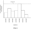
- One or more components may be particularly susceptible to fatigue damage caused by over-rating. For example, as shown in Figure 5 , after 20 years of operation one component may reach the 20 year lifetime fatigue limit, whereas other components still have some lifetime in reserve. In this case, replacing the component or components that are incurring a greater rate of fatigue damage allows AEP to be increased. Factored in over the life of the turbine, and taking into account the total cost of the replacement, this may still increase the profitability of the turbine when calculating the NPV.
- a schedule of maximum power level values it is also possible to specify a schedule of fatigue damage, or fatigue life remaining, since rate of fatigue damage incurred is related to the maximum power level setting of the turbine.
- the turbine power output is then controlled to maintain the fatigue life remaining to that specified by the schedule, for example by using LUEs to track fatigue life in the turbine controller.
- an energy schedule could also be used, since this would still be indicative of how the turbine maximum power level varies over time.
- the energy schedule could be per annum or per calendar month or similar.
- the schedules may also have non-linear shapes, such as following the shape of a polynomial curve.
- schedules Whilst the schedules are shown as varying continuously over their duration, they may vary in a stepped fashion, specifying a given maximum power level over a particular period of time such as a month, season or year.
- the schedule may, for example, be a series of annual values over the lifetime of the turbine.
- Schedules may be calculated once, or the calculation may be repeated at intervals.
- the schedules may be calculated monthly or yearly.
- a schedule that specifies a maximum power level on a yearly basis it may be advantageous to calculate the schedule every month or week (for example), because changes to the schedule may alert the user to parameters that are changing more quickly than expected.
- this calculation may take place before the wind power plant is commissioned, or it may take place at any time post-commissioning.
- the first calculation may take place before the wind power plant is commissioned, or may take place at any time post-commissioning.
- a control schedule is produced that can be used to control a wind turbine.
- a relative schedule may be defined, and one or more of a minimum wind turbine life or a maximum number of major component replacements may be defined.
- the schedule is then adjusted to ensure that the fatigue lifetime of the turbine meets the target lifetime whilst maximising AEP.
- a wind turbine is operated according to one of the over-rating control techniques described herein using an over-rating controller, which may be implemented by the wind turbine controller.
- Lifetime Usage Estimators may be used to determine and monitor the lifetime usage of components. Lifetime Usage Estimators may be used in ensuring the fatigue load limits of all turbine components remain within their design lifetimes. The loads a given component experiences (be they bending moments, temperatures, forces or motions for example) may be measured and the amount of component fatigue life consumed calculated, for example using a technique such as a rainflow count and Miner's rule or a chemical decay equation. Based on Lifetime Usage Estimators, individual turbines can then be operated in such a way as to not exceed their design limits.
- LUEs Lifetime Usage Estimators
- a device, module, software component or logical component for the measuring of the fatigue life consumed for a given turbine component may also be referred to as its Lifetime Usage Estimator, and the same acronym (LUE) will be used to refer to the algorithm for determining a lifetime usage estimate and the corresponding device, module or software or logic component. LUEs are described in more detail below.
- the over-rating controller will control the amount of over-rating applied based on a function or schedule over the expected or certified lifetime of the wind turbine. Typically this is 20 or 25 years.
- the controller is configured to receive input parameters, for example from a site operator, the input defining a new target lifetime for the wind turbine or for one or more specific turbine components.
- the lifetime usage to date of the turbine, or the relevant turbine components is determined using the LUEs. This puts a constraint on the amount of component lifetime remaining for the wind turbine, and therefore on the control schedule.
- the revised target lifetime puts a constraint on the amount of time over which the remaining component life must extend.
- the future available fatigue lifetime may be calculated offline or online using site check software, and this is used to specify the revised control schedule.
- the site check function may include a calculation, or one or more simulations, to determine the expected rate of fatigue damage using site based historical data, including measured site climatic data prior to construction, and/or measured site climatic data post-construction, and/or data from LUEs.
- Site climatic data typically includes data from a met mast or ground-based LIDAR, and may include wind speed, turbulence intensity, wind-direction, air density, vertical wind shear and temperature. Site check calculations may be performed remotely, or by the turbine/power plant level controllers as appropriate.
- the site check software may be populated with information or parameters relating to the given WPP site topography, terrain, wind conditions, and so on.
- the topography and terrain information may be provided by site surveys and/or from knowledge of the WPP site, which may include details of slopes, cliffs, inflow angles to each turbine in the WPP, and so on.
- Wind conditions e.g. wind-speeds (seasonal, annual, etc.), turbulence intensity (seasonal, annual, etc.), air density (seasonal, annual, etc.), temperature (seasonal, annual, etc.), and so on, may be provided from Met Mast data and/or from wind conditions experienced and logged by the wind turbines and/or WPPC in location at the WPP.
- the site check tool may comprise one or more memory, database, or other data structure, to store and maintain the fatigue load values for each type of wind turbine, wind turbine type maximum power levels for each type of wind turbine, and information and/or parameters relating to the WPP site conditions.
- a revised control schedule is therefore generated, whereby the additional power produced by over-rating is adjusted such that the turbine is exposed to a higher or lower rate of accumulation of fatigue damage, depending on whether the new target date for end-of-life is earlier or later than the previous target date, which may be the certified lifetime.
- the ability to revise the turbine control schedule allows the operator to change their priorities over time. For example, a major generator on the local grid might be taken out of operation for a mid-life overhaul, or may be retired completely, and the grid may need additional support. This may be reflected in substantially higher long-term tariffs, and so it would be advantageous for the operator to increase energy production in the short term.
- the operator can therefore decide to reduce turbine life, or the life of affected components such as the gearbox and generator, and generate additional power by over-rating, while accepting shorter wind turbine or turbine component life.
- the site check function may again include an offline or online calculation, or one or more simulations, to determine the expected rate of fatigue damage using site based historical data or measured site data to the point of installation, although in this case the calculation is made without LUE data available.
- Operation of a wind turbine up to the date of fitting of the over-rating controller that employs the functionality described herein may be examined using site check software to calculate fatigue loads on turbine components based upon input parameters specifying site topography, site terrain, site meteorological conditions etc. using measured values relating to the wind turbine's precise location within the wind power plant site, such as one or more of energy output, wind speed, wind direction, turbulence intensity, wind shear, air density, turbine mechanical load measurements (for example from blade load sensors), turbine electrical component temperatures and loads, icing events, component temperatures and condition monitoring system outputs. These values may be used to calculate an estimate for fatigue damage that has occurred so far to the turbine components.
- the future lifetime available for the turbine, or the turbine components may be calculated by applying the measured values to a site check function wind turbine model or simulation that provides as an output estimated fatigue damage and/or remaining fatigue life based on one or more of these measured values and a value for the wind turbine type maximum power level of the turbine.
- the simulation or model may provide fatigue damage and/or remaining fatigue life at the component level, or for the turbine as a whole. Fatigue load calculations may be performed according to various calculation procedures. Various examples of such site checking programs will be known to the skilled person and will not be described in detail.
- the resulting estimation of the consumed fatigue life of the turbine or turbine components may be used to determine the over-rating strategy applied by the controller.
- the estimation may be used once, at initialisation of the over-rating control, which may be performed partway through the life of the turbine if being retrofitted. Alternatively, the estimation may be performed periodically during the life of the turbine such that over-rating strategy is periodically updated depending upon how the lifetime fatigue consumption changes throughout turbine life.
- Over-rating strategy is determined based upon remaining fatigue life of the wind turbine, or wind turbine components, which is itself based upon the operating lifetime of the wind turbine.
- the amount of over-rating applied is controlled such that fatigue damage is incurred by the turbine or turbine components at a sufficiently low rate to ensure that the fatigue life of the turbine is only used up at the end, and preferably only just at the end, of the predetermined turbine life.
- condition monitoring systems comprise a number of sensors at strategic points of the drive-train system, in the turbine gearbox, generator or other key components.
- Condition monitoring systems provide early warnings of component failures, before the component has actually failed.
- the output from condition monitoring systems may therefore be provided to the controller and used as an indication of the fatigue lifetime consumed by the monitored components, and can particularly provide an indication of when the fatigue lifetimes for the components are reaching their end. This provides an additional way to estimate the lifetime used.
- a second example is provided for carrying out a more general optimisation process, which may be used to carry out similar sorts of optimisation to that described above, as well as other more general optimisations.
- the optimisation process of the second example may be carried out by a controller applying an optimisation scheme.
- LCoE levelised cost of energy
- a full financial cost, or levelised cost of energy (LCoE) model of the turbine is included, and used either in off-line calculations prior to installation of an over-rating control system, or used online as part of the wind turbine controller or wind power plant controller.
- Use of the LCoE model allows optimisation of the over-rating strategy and may also factor in replacement of main components based upon the cost of doing so.
- Levelised Cost of Energy refers to a measure of the cost of energy from a turbine that is calculated by dividing the lifetime costs of the turbine by the lifetime energy output of the turbine.
- Figure 6 shows an example of a simplified LCoE model in which the various costs associated with building and operating a wind turbine, and wind turbine power plant, are taken into account.
- the transport cost factors the cost of transporting the turbine components to the site for installation.
- the capacity factor indicates the energy generated over a given period, for example one year, divided by the energy that could have been generated if the turbine were to have operated continuously at rated power during that period.
- the availability indicates the time the turbine will be available to generate electricity.
- the park efficiency indicates the efficiency of extraction of energy from the wind, and is affected by the spacing of turbines within the park.
- LCoE Only those elements of LCoE that are affected by the control and component replacement strategy need to be included in the LCoE model, since a number of parameters that may be included in an LCoE model become fixed when the turbine or wind park has been constructed.
- the affected elements are:
- Having a financial cost (LCoE) model of the turbine included in the turbine or WPP controller allows for more flexible and efficient control strategies to be determined. For example, if conditions at a particular site are found to be particularly hard on gearboxes then this will be identified and the operator can choose whether to over-rate the turbine and factor in replacing the gearbox a certain number of times. Then the turbine controller can determine when a gearbox should be replaced, run the turbine accordingly, and optionally also provide an indication of when to replace the gearbox.
- LoE financial cost
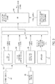
- Figure 7 shows a block diagram of an example optimiser for optimising the wind turbine control strategy, and which may be incorporated into a controller, and which may be used to implement various embodiments of the invention.
- the block marked "Initialise” is run once. This provides initial conditions for the optimisation loop.
- the loop marked “Optimise” is executed periodically, for example once per day, per month or per year. When it is executed, the loop runs as many times as needed to achieve sufficiently good convergence of the optimisation process. Following convergence, the new set of outputs is sent to the wind turbine controller (x1) and to the operator (the other outputs) for implementing the determined control strategy.
- the two blocks “calculate estimate of LCoE” contain identical calculation methods. They include all the elements of Figure 6 which are not already fixed, i.e. the O&M cost, capacity factor, availability and lifetime. For example, the tower CAPEX is already fixed, so that does not need to be included. But the operation and maintenance (O&M) cost is not fixed, as the gearbox could be worked harder and replaced once during the lifetime of the turbine, so this is included.
- the optimisation procedure requires the determination of a number of constants for a given turbine and calculating an initial condition for the optimisation using the values of a number of physical and control parameters. Once the initial condition has been calculated, the optimisation process applies a function defining a relationship between levelised cost of energy and input values for the physical and control parameters to determine the combination of input values that minimises the levelised cost of energy without exceeding certain optimisation constraints.
- a number of parameter values for a given turbine are ascertained and input into the "Initialise" block.
- these values are constant. They are parameters input by the operator, and can be changed at any time but, if changed, will be applied the next time the optimisation is run. These parameters may include one or more of: lifetime of turbine/individual turbine components; gearbox replacement cost; bearing replacement cost; generator replacement cost; blade replacement cost; pitch system replacement cost; and replacement cost of any other components as necessary.
- the lifetime of the turbine, and/or the lifetime of one or more components are determined, for example using a site check function and/or one or more LUEs, or may be provided as a constraint to be met.
- the replaceable components include the blades, pitch bearing, pitch actuation system, hub, main shaft, main bearing, gearbox, generator, converter, yaw drive, yaw bearing or transformer.
- the total cost of replacing each of the components is determined. For example, for a replacement gearbox, the cost will take into account whether a new or refurbished gearbox is being fitted, the transport costs, and crane and labour costs. Turbine downtime costs are also included, under the Availability section in Figure 6 .
- WACC weighted average cost of capital
- the lifetime parameters may be set by the operator depending on their operational strategy for the site, or may be determined as part of the optimisation.
- the other constants are based on best knowledge, so they may be updated occasionally, but such updates would be fairly rare.
- the O&M costs can only be estimated in advance, and these estimates are replaced with real data as time passes, thereby giving rise to more accurate estimates of future O&M costs.
- the initial calculation of an estimate of LCoE uses initial estimates from the operator for the initial conditions, x1_0, x2_0, x3_0, etc.
- Measured data from sensors may be from the turbine or wind power plant and may include one or more of:
- Measured data from operation and maintenance (O&M) activities consists of O&M costs, which may include an estimate based on costs to date (if any). This is used, together with the future scheduled service pattern, experience from other turbines of the same design at the same or at other wind power plants, and experience for certain components of other turbines of different designs that use the same component, to give an estimate of future O&M cost in the LCoE calculation.
- the optimisation process uses the inputs and constraints to minimise the levelised cost of energy (LCoE), either by calculating the LCoE directly or by calculating certain LCoE variables. Only the part of the LCoE that varies after construction of the turbine needs to be calculated, i.e. the proportion affected by O&M cost, capacity factor, availability and lifetime. The optimisation is run until the LCoE is minimised, for example until the change in the calculated LCoE from step to step is within a given tolerance.
- LCoE levelised cost of energy
- the constraints on the optimisation are regions in which the optimisation algorithm cannot enter when searching for the minimum value of LCoE.
- the constraints may include one or more of: wind turbine type maximum power level; minimum power output of the turbine type; maximum active power capacity of the wind power plant's connection to the electricity grid, i.e. maximum sum of all turbines' active power output; and any other appropriate constraints.
- the constraints may also include one or more of the following, which may be defined by a user:
- the number of inputs for each one dimensional array may be selected to make the optimisation algorithm's run-time more manageable.
- the one dimensional arrays x1, x2 etc. are described above as being provided for every year of operation. Whilst it is possible to provide inputs for every month or season of operation, this would provide 12 times, or 4 times, as many inputs. Therefore annual values may be used. Of course, different time periods may be used as appropriate, depending upon the desired computation time, or granularity of the optimisation.
- the wind turbine components may be selected such that only the most relevant components are used in the optimisation.
- Components to be included may be selected on the basis of whether their lifetime is significantly affected by active power output above rated wind-speed, particularly the gearbox, generator, main bearing and blades.
- the components used in the optimisation may be selected based upon their value. For example, only components which have a value of 5% or more of the turbine total cost may be included.
- the optimiser algorithm generates a number of outputs each time it is run to convergence.
- the one dimensional array x1, representing a schedule of maximum power levels for years 1... N for the turbine may be used in closed-loop control by automatically communicating the data to the wind turbine controller to be used as the turbine power demand until the next time that the optimisation loop is run (e.g. 1 month later).
- the maximum power levels may be used without an automatic control loop, in an advisory capacity, for example by sending the maximum power level data to a computer system for output on a display for viewing by the service department.
- the other one dimensional arrays x2, x3, x4, represent a schedule for the replacement of components.
- This schedule data may be output to another computer system to allow action to be taken.
- the data may be provided directly into component replacement scheduling software.
- the component replacement data, including suggested replacement dates, may be used as an advisory output sent to a display for viewing by the service department to decide upon a manual implementation of component replacement plans.
- the one dimensional array of maximum power levels (x1) described above may be provided as over-rated levels only, over-rated or de-rated levels, or de-rated levels only., such that the maximum power level variable would only need to specify the amount above (or below) rated power.
- the power demand could alternatively be a speed demand and/or a torque demand for each period, or a fatigue lifetime consumption where power is controlled by a life use control function as described below.
- the disadvantage or using both a speed demand and a torque demand is that the computing time for calculating the optimal configuration will be longer.
- the optimiser is described above as being executed periodically, it may be used sporadically, or even only once.
- the optimisation may be performed offline, at the point of installing an over-rating controller.
- the optimiser may be embodied in a controller, either at the wind turbine, the wind power plant, or elsewhere, in which case it will be executed at a particular time step.
- the optimisation may be performed with or without LUEs, since site data can be used to determine component fatigue, and thus give an indication of remaining lifetime available for the turbine or turbine components.
- the optimisation algorithm has been described primarily in relation to use with an over-rating controller, this is not a requirement.
- the optimisation could be applied with any control action that trades off energy capture against turbine fatigue loading. This could include one or more of: changing power demand such as by de-rating; thrust limiting, which limits power output to prevent high thrust loads by reducing rotor thrust at the 'knee' of the power curve at the expense of power output; or any other control feature that trades off energy capture and fatigue loads.
- a method for determining a Wind Turbine Type Maximum Power Level for a type of wind turbine may comprise: simulating a load spectrum for two or more test power levels to determine a load on the type of wind turbine for each of the two or more test power levels; comparing the determined load for each test power level with a design load for the type of wind turbine; and setting the wind turbine type maximum power level for the type of wind turbine as the maximum test power level at which the determined load does not exceed the design load for the type of wind turbine.
- a Wind Turbine Type Maximum Power Level can be determined for one or more types of wind turbine.
- Figure 8 shows a flow chart detailing an example of setting turbine maximum power levels that may be used with any embodiments.
- step 301 a check is performed to determine the wind turbine mechanical component design limits for one or more types of wind turbines.
- an offline computer system is utilized to determine the design limits.
- the functionality may be implemented by an online computer system, or any other software and/or hardware associated with wind turbines and/or WPP.
- the wind turbine type maximum power level is the maximum power level that a given type of wind turbine is allowed to produce when the wind is suitably high if it is to be operated at the limit of the design loads of the components of the wind turbine.
- the wind turbine type maximum power level effectively applies for the design lifetime of the turbine. Therefore, the wind turbine type maximum power level will typically be higher than the nominal name-plate rating for that type of wind turbine as the nominal name-plate rating is typically a more conservative value.
- a type of wind turbine may be understood as a wind turbine with the same electrical system, mechanical system, generator, gearbox, turbine blade, turbine blade length, hub height, and so on. Accordingly, any difference to the main structure or components of a wind turbine effectively generates a new type of wind turbine, for the purpose of the embodiments of the present invention.
- the same wind turbine except for different hub heights e.g. tower heights
- the same wind turbine except of different turbine blade lengths would also be considered two different types of wind turbine.
- a 50Hz and 60Hz wind turbine are considered different types of wind turbine, as are cold climate and hot climate designed wind turbines.
- the type of wind turbine therefore does not necessarily correspond to the International Electrotechnical Commission (IEC) class of wind turbine as different types of turbine may be in the same IEC class of wind turbine where each type of wind turbine may have a different wind turbine type maximum power level based on the design of and components in the wind turbine.
- IEC International Electrotechnical Commission
- the wind turbine is rated at a nominal plate rating power level of 1.65MW (1650 KW), with a hub height of 78 metres and designed for service in the conditions of a specific IEC Wind Class.
- the wind turbine type mechanical components' design limit may then be determined for this type of wind turbine by simulating a load spectrum for a first test over-rate power level to identify the loads on the type of wind turbine for that first power level.
- the loads may be mechanical loads, fatigue loads, any other loads that may be experienced by the wind turbine, or any combination of the different loads.
- the mechanical loads are considered however, as will be appreciated, other loads, e.g. fatigue loads could also be taken into account.
- the process of simulating the load spectrum may also include or be an extrapolation or other form of analysis that may be performed to determine the load on the type of wind turbine.
- a load spectrum typically includes a range of different test cases which may be run in a computer simulation of a wind turbine.
- the load spectrum may include test cases for winds at 8m/s for duration of 10 minutes, for 10m/s for 10 minutes, for different wind directions, for different wind turbulences, for startup of the wind turbine, for shutdown of the wind turbine, and so on.
- the test cases may include real, actual data or artificial data (e.g. for 50 year gusts that are defined in the standards relating to wind turbines).
- the simulation of the load spectrum may determine the forces and loads affecting the wind turbine for all test cases in the load spectrum. This simulation may also estimate or determine the number of times that the test case event may occur, for example, a test case of 10 m/s wind for a duration of 10 minutes may be expected to occur 2000 times during the 20 year lifetime of the wind turbine and therefore the fatigue on the wind turbine for the lifetime of the wind turbine can be calculated. The simulation may also calculate or determine the fatigue damage or load that could be incurred by the various components in the wind turbine based on the determined loads affecting the wind turbine.
- the first test power level may be 1700KW as this is higher than the nominal name-plate rating power level for the type of wind turbine being considered in this example.
- the load spectrum may then be simulated for the given type of wind turbine in order to determine whether the type of wind turbine can operate at that first test power level without exceeding the ultimate design loads of the mechanical components of the type of wind turbine. If the simulation identifies that the type of wind turbine can operate at the first test power level then the same process may be repeated for a second test power level.
- the second test power level in this example, may be 1725KW.
- the load spectrum is then simulated for the given type of wind turbine to identify whether that type of wind turbine can operate at that second test power level without exceeding the ultimate design loads of the mechanical components.
- the process of simulating the load spectrum for further test power levels can be iteratively performed.
- the test power levels are incremented at steps of 25KW however, as will be appreciated, the incremental steps may be any suitable for the purpose of identifying the wind turbine type maximum power level, e.g. 5KW, 10KW, 15KW, 20KW, 30KW, 50KW, and so on, or increase by a percentage of the test power level, e.g. 1% increments, 2% increments, 5% increments, and so on.
- the process start at a high first test power level and for each iteration decrements the test power level by a suitable amount until the wind turbine type maximum power level is identified, i.e. the first test power level at which the type of wind turbine can operate without exceeding ultimate design limitations.
- the given type of wind turbine is identified as being able to operate at further test power levels of 1750KW, 1775KW and 1800KW before a design limitation of one or more mechanical components is exceeded at 1825KW.
- the process identifies that the wind turbine type maximum power level for this type of turbine is 1800KW.
- the process could further iteratively increment the test power levels by smaller increments, e.g. 5KW to identify whether the wind turbine could operate without exceeding the mechanical ultimate design loads at a power level between 1800KW and 1825KW.
- the power level of 1800KW is taken as the wind turbine type mechanical component design limit for this type of wind turbine.
- the process of determining the wind turbine type maximum power level may then be performed for any further types of wind turbine that are to be analysed.
- the design limitations for the electrical components in the type of wind turbine may be considered or evaluated for the previously determined wind turbine mechanical component design limits.
- the main electrical components may be considered to ensure that the determined wind turbine type power level for the mechanical component design limits does not exceed the design limitations of the main electrical components of the type of wind turbine being analyzed.
- the main electrical components may include, for example, the generator, transformer, internal cables, contactors, or any other electrical component in the type of wind turbine.
- the main electrical components can operate at the previously determined wind turbine type maximum power level for the mechanical component design limits. For example, operation at the mechanical components design limit power level may cause a temperature of one or more electrical cables inside the wind turbine to increase and so reduce the electrical current carrying capability of the electrical cables, which is determined by the size of cable conductor and the conditions for thermal dissipation. Therefore, the current carrying capacity would be calculated for the new temperature conditions in order to determine if the electrical cables are able to operate at power levels up to the wind turbine type maximum power level. Similar considerations may be taken into account for other electrical components, e.g. the temperature of the components, capacity of the components and so on, to identify whether the electrical components can operate at power levels up to the mechanical component design limits.
- step 303 of Figure 8 for the given type of wind turbine the wind turbine type maximum power level is set or recorded as the maximum power level for the given type of wind turbine in accordance with the mechanical component design limits. If however it is determined or identified that the main electrical components cannot operate at the previously determined mechanical component design limits, then further investigation or action can be taken to arrive at a turbine type maximum power level that accommodates both the mechanical and electrical components.
- this parameter may be utilized as a constraint within the methods described above, to arrive at a schedule of individual maximum power levels, e.g. the maximum over-rating power level, for each wind turbine in a WPP
- Different individual maximum power levels for each wind turbine in a WPP are advantageous as the conditions in a WPP may vary across the site of the WPP. Therefore, it may be the case that a wind turbine in one location in the WPP may face different conditions to another wind turbine of the same type at a different location in the WPP. Accordingly, the two wind turbines of the same type may require different individual maximum power levels, or the lowest individual maximum power level may be applied to all wind turbines of that type in the WPP depending on the preferred implementation. Individual wind turbine specific individual maximum power levels are determined as part of determining the schedule, as described herein.
- Embodiments of the invention may be applied to wind turbines, or to wind power plants, that are operated by applying over-rating control to determine the amount of over-rating to apply.
- An over-rating control signal is generated by an over-rating controller and is used by a wind turbine controller to over-rate the turbine.
- the control schedule described above can be used within, or in conjunction with, such an over-rating controller to set an upper limit on the amount of power that can be generated by over-rating.
- the specific manner in which over-rating control signals are generated is not crucial to embodiments of the present invention, but an example will be given for ease of understanding.
- Each wind turbine may include an over-rating controller as part of the wind turbine controller.
- the over-rating controller calculates an over-rating request signal indicating an amount up to which the turbine is to over-rate the power output above rated output.
- the controller receives data from the turbine sensors, such as pitch angle, rotor speed, power output etc., and can send commands, such as set points for pitch angle, rotor speed, power output etc.
- the controller may also receive commands from the grid, for example from the grid operator to boost or reduce active or reactive power output in response to demand or a fault on the grid.
- FIG. 9 shows a schematic example of a turbine controller arrangement in which an overrating controller 901 generates an over-rating control signal that can be used by wind turbine controllers to apply over-rating to the turbine.
- the over-rating control signal may be generated depending upon the output of one or more sensors 902/904 that detect operating parameters of the turbine and/or local conditions such as wind speed and direction.
- the over-rating controller 901 comprises one or more functional control modules that may be used in various aspects of over-rating control. Additional functional modules may be provided, the functions of modules may be combined and some modules may be omitted.
- the value for individual turbine maximum power level is provided by the optimiser 907 according to the schedule determined as described herein. This provides the maximum power level to which the turbine can be operated to, according to the schedule.
- the additional functional modules generate power demands, and will generally serve to reduce the final power demand acted upon by the turbine controller.
- a specific example of an additional functional module is the operational constraints module 906. Over-rating exploits the gap that typically exists between the component design-loads and the loads experienced by each turbine in operation, which are typically more benign than the IEC-standard simulated conditions in which the design loads were calculated. Over-rating causes the power demand for the turbine to be increased in high winds until either an operating limit specified by an operational constraint (temperature, etc.) is reached, or until an upper power limit is reached that has been set to prevent the exceedance of component design loads.
- Operational constraints implemented by operational constraints control module 906, limit the possible over-rating power demand as a function of various operating parameters.
- an operational constraint may dictate a linear decrease in the maximum possible over-rating set point signal as a function of gearbox oil temperature for temperatures over 60°C, reaching "no over-rating possible" (i.e., a power set-point signal equal to rated power) at 65°C.
- the maximum power level and the power demands from the functional modules are provided to a minimum function, block 908, and the lowest value is selected.
- a further minimum block 909 may be provided that selects the minimum power demand from the over-rating controller 901 and any other turbine power demands, such as those specified by a grid operator, to produce the final power demand applied by the wind turbine controller.
- the over-rating controller may be part of the PPC controller 130 of Figure 1B for example.
- the PPC controller communicates with each of the turbines and can receive data from the turbines, such as pitch angle, rotor speed, power output etc and can send commands to individual turbines, such as set points for pitch angle, rotor speed, power output etc.
- the PPC 130 also receives commands from the grid, for example from the grid operator to boost or reduce active or reactive power output in response to demand or a fault on the grid.
- Each wind turbine's controller communicates with the PPC 130.
- the PPC controller 130 receives power output data from each of the turbines and is therefore aware of the power output by each turbine and by the plant as a whole at the grid connection point 140. If required, the PPC controller 130 can receive an operating set point for the power output of the power plant as a whole and divide this among each of the turbines so that the output does not exceed the operator assigned set point.
- This power plant set point may be anywhere from 0 up to the rated power output for the plant.
- the "rated power" output for the plant is the sum of the rated power output of the individual turbines in the plant.
- the power plant set point may be above the rated power output of the plant, i.e. the whole plant is over-rated.
- the PPC may receive an input directly from the grid connection, or it may receive a signal which is a measure of the difference between the total power plant output and the nominal or rated power plant output. This difference can be used to provide the basis for over-rating by individual turbines. In theory, only a single turbine may be over-rated, but it is preferred to over-rate a plurality of the turbines, and most preferred to send the over-rating signal to all the turbines.
- the over-rating signal sent to each turbine may not be a fixed control, but may instead be an indication of a maximum amount of over-rating that each turbine may perform.
- Each turbine may have an associated controller, which may be implemented within the turbine controller or centrally such as at the PPC, which will implement one or more of the functions shown in Figure 9 to determine whether the turbine can respond to the over-rating signal and, if so, by what amount. For example, where the controller within the turbine controller determines that conditions at a given turbine are favourable and above rated wind speed it may respond positively and the given turbine is over-rated. As the controllers implement the over-rating signal, the output of the power plant will rise.
- An over-rating signal is therefore generated, either centrally or at each individual turbine, the signal being indicative of the amount of over-rating that may be performed by one or more turbines, or the turbines of the power plant as a whole.
- Embodiments of the invention make use of Lifetime Usage Estimators (LUEs).
- LUEs Lifetime Usage Estimators
- the lifetime usage estimators will now be described in more detail.
- the algorithm required to estimate lifetime usage will vary from component to component and the LUEs may comprise a library of LUE algorithms including some or all of the following: load duration, load revolution distribution, rainflow counting, stress cycle damage, temperature cycle damage, generator thermal reaction rate, transformer thermal reaction rate and bearing wear. Additionally other algorithms may be used.
- lifetime usage estimation may only be used for selected key components and the use of a library of algorithms enables a new component to be selected for LUE and the suitable algorithm selected from the library and specific parameters set for that component part.
- LUEs are implemented for all major components of the turbine including blades; pitch bearings; pitch actuators or drives; hub; main shaft; main bearing housing; main bearings; gearbox bearings; gear teeth; generator; generator bearings; converter; generator terminal-box cable; yaw drives; yaw bearing; tower; offshore support structure if present; foundation; and transformer windings.
- blades pitch bearings; pitch actuators or drives; hub; main shaft; main bearing housing; main bearings; gearbox bearings; gear teeth; generator; generator bearings; converter; generator terminal-box cable; yaw drives; yaw bearing; tower; offshore support structure if present; foundation; and transformer windings.
- a selection of one or more of these LUEs may be made.
- rainflow counting may be used in the blade structure, blade bolts, pitch system, main shaft system, converter, yaw system, tower and foundation estimators.
- the rainflow count is applied to the blade root bending flapwise and edgewise moment to identify the stress cycle range and mean values and the output is sent to the stress cycle damage algorithm.
- the rainflow count is applied to the bolt bending moment to identify stress cycle range and mean values and the output sent to the stress cycle damage algorithm.
- the rainflow counting algorithm is also applied to identify the stress cycle range and mean values and the output sent to the stress cycle damage algorithm.
- the parameters to which the rainflow algorithm is applied may include:
- the rainflow algorithm is applied to the tower top torsion to identify the load duration and this output is sent to the stress cycle damage algorithm.
- generator power and RPM is used to infer the temperature and rainflow counting is used on this temperature to identify the temperature cycle and mean values.
- Lifetime usage in the blade bearings may be monitored either by inputting blade flapwise load and pitch velocity as inputs to the load duration algorithm or to a bearing wear algorithm.
- the load revolution duration is applied to the main shaft torque to calculate the lifetime used.
- generator RPM is used to infer generator temperature which is used as an input to the thermal reaction rate generator algorithm.
- the transformer temperature is inferred from the power and ambient temperature to provide an input to the transformer thermal reaction rate algorithm.
- Any of the methods described herein may be performed at the wind power plant level, whereby a power plant control schedule is generated that comprises individual control schedules for each wind turbine. This has the benefit of allowing the interactions between turbines in a given power plant to be taken into account.
- the site check software includes information on the positioning of turbines within a wind power plant, and takes into account the relative positions of turbines relative to each other within the wind farm. Wake effects from upstream turbines are therefore factored into calculations by site check software.
- the power-carrying capacity of the connection from the power plant to the utility grid is less than the sum of the power that is generated by each turbine in the case when all turbines are generating power at the Wind Turbine Type Maximum Power Level.
- the control schedules of the wind turbines, or of the wind power plant are further constrained so that, for any given time period within the schedule, when the power of all of the turbines is added together it does not exceed the amount of power that can be carried in the connection from the power plant to the grid.
- Embodiments described herein rely on analysis of turbine properties and turbine site properties, in the determination of a control schedule for a turbine.
- the various calculations, including those performed by site check software, may be implemented offline, at one or more different computing systems, and the resulting control schedule is provided to the wind turbine or power plant controller. Alternatively, the calculations may be performed online at the wind turbine controller or power plant controller.
- inventions of the invention may be applied to both constant-speed and variable-speed turbines.
- the turbine may employ active pitch control, whereby power limitation above rated wind speed is achieved by feathering, which involves rotating all or part of each blade to reduce the angle of attack.
- the turbine may employ active stall control, which achieves power limitation above rated wind speed by pitching the blades into stall, in the opposite direction of that used in active pitch control.
Claims (26)
- Verfahren zum Erzeugen eines Steuerungsplans für eine Windkraftanlage (1), wobei der Steuerungsplan anzeigt, wie der maximale Windkraftanlagenleistungspegel über die Zeit variiert, wobei das Verfahren umfasst:Bestimmen eines Wertes, der die aktuell verbleibende Ermüdungslebensdauer der Windkraftanlage (1) oder einer oder mehrerer Windkraftanlagenkomponenten basierend auf Daten, die am Standort der Windkraftanlage gemessen werden, und/oder Betriebsdaten anzeigt;Anwenden einer Optimierungsfunktion, die einen anfänglichen Steuerungsplan variiert, um einen optimierten Steuerungsplan zu bestimmen, indem der Kompromiss zwischen Energiegewinnung und Ermüdungslebensdauer, die durch die Windkraftanlage (1) oder die eine oder die mehreren Windkraftanlagenkomponenten verbraucht wird, variiert wird, bis ein optimierter Steuerungsplan bestimmt ist, wobei die Optimierung umfasst:Schätzen einer zukünftigen Ermüdungslebensdauer, die durch die Windkraftanlage (1) oder die Windkraftanlagenkomponente über die Dauer des variierten Steuerungsplans verbraucht wird, basierend auf der aktuell verbleibenden Ermüdungslebensdauer und dem variierten Steuerungsplan; undBeschränken der Optimierung des Steuerungsplans gemäß einer oder mehrerer Eingangsbeschränkungen;wobei die Optimierung weiter ein Variieren eines Anfangswertes für eine Windkraftanlagenlebensdauer und ein Variieren eines Anfangswertes für die Anzahl von Komponentenauswechslungen für eine oder mehrere Komponenten, die im Verlauf des Plans durchgeführt werden sollen, beinhaltet, um eine Kombination der Anzahl von Komponentenauswechslungen für eine oder mehrere Windkraftanlagenkomponenten und der Windkraftanlagenlebensdauer zu bestimmen, wobei die Windkraftanlagenlebensdauer als eine angestrebte minimale Windkraftanlagenlebensdauer bestimmt wird.
- Verfahren nach Anspruch 1, wobei der anfängliche Steuerungsplan die relative Variation des maximalen Windkraftanlagenleistungspegels, bis zu dem die Windkraftanlage (1) betrieben werden kann, über die Zeit spezifiziert.
- Verfahren nach Anspruch 1 oder 2, weiter umfassend:
Optimieren des Steuerungsplans durch Variieren des Zeitpunkts und der Anzahl von Komponentenauswechslungen bis zu der maximalen Anzahl. - Verfahren nach einem vorstehenden Anspruch, wobei die Eingangsbeschränkungen weiter die obere maximale Ausgangsleistung der Windkraftanlage (1), die durch die Windkraftanlagengestaltung zulässig ist, und/oder die minimale Ausgangsleistung der Windkraftanlage (1) umfasst.
- Verfahren nach einem vorstehenden Anspruch, wobei das Bestimmen eines Wertes, der die aktuell verbleibende Ermüdungslebensdauer der Windkraftanlage (1) oder einer oder mehrerer Windkraftanlagenkomponenten anzeigt, umfasst:Anwenden von Sensordaten von einem oder Mehreren Windkraftanlagensensoren auf einen oder mehrere Algorithmen zur Schätzung der Lebensdauernutzung, oderVerwenden von Daten von einem Zustandsüberwachungssystem, oderVerwenden von Daten, die von Windparksensoren erhalten werden, in Kombination mit einem Standortüberprüfungsprogramm, das basierend auf den Windparksensoren und Parametern, die sich auf die Gestaltung des Windparks und der Windkraftanlage beziehen, Lasten bestimmt, die auf Windkraftwerkskomponenten wirken.
- Verfahren nach einem vorstehenden Anspruch, wobei die Optimierung des Steuerungsplans umfasst:
Variieren des Steuerungsplans, um die ausgeglichenen Energiekosten (LCoE) zu minimieren. - Verfahren nach Anspruch 6, wobei ein LCoE-Modell verwendet wird, um LCoE zu bestimmen, wobei das Modell Parameter beinhaltet für eines oder mehrere von:einem Kapazitätsfaktor, der die über einen Zeitraum erzeugte Energie dividiert durch die Energie, die hätte erzeugt werden können, wenn die Windkraftanlage (1) während dieses Zeitraums kontinuierlich bei Nennleistung betrieben worden wäre, anzeigt;einer Verfügbarkeit, die die Zeit anzeigt, zu der die Windkraftanlage (1) verfügbar ist, um Elektrizität zu erzeugen; undeiner Parkeffizienz, die die über einen Zeitraum erzeugte Energie dividiert durch die Energie, die hätte erzeugt werden können, wenn die Windkraftanlage (1) in Wind betrieben worden wäre, der von stromaufwärtigen Windkraftanlagen völlig ungestört war, anzeigt.
- Verfahren nach Anspruch 7, wobei das Modell weiter Parameter beinhaltet für eines oder mehrere von:Kosten, die mit dem Auswechseln einer oder mehrerer Komponenten verbunden sind, einschließlich Stillstandszeiten der Windkraftanlage, Arbeitsaufwand und Ausrüstung für die Komponentenauswechslung, Herstellungs- oder Aufarbeitungskosten Auswechslungskomponenten und Transportkosten der aufgearbeiteten Komponenten oder Auswechslungskomponenten zu dem Kraftwerk; undServicekosten, die mit der Auswechslung von Verschleißteilen verbunden sind.
- Verfahren nach einem vorstehenden Anspruch, wobei der optimierte Steuerungsplan ein Plan der maximalen Leistungspegel ist, bis zu denen die Windkraftanlage (1) betrieben werden kann.
- Verfahren nach einem der Ansprüche 1 bis 8, wobei der Steuerungsplan die Menge an Ermüdungsschäden anzeigt, die über die Zeit aufgetreten sein sollten, wobei das Verfahren weiter ein Betreiben der Windkraftanlage (1) basierend auf einer oder mehreren LUEs umfasst, um Ermüdungsschäden mit einer durch den Steuerungsplan angezeigten Rate zu erleiden.
- Verfahren nach einem vorstehenden Anspruch, wobei der Steuerungsplan anzeigt, wie der maximale Windkraftanlagenleistungspegel über die Lebensdauer der Windkraftanlage (1) variiert.
- Verfahren nach einem vorstehenden Anspruch, weiter umfassend ein Bereitstellen des optimierten Steuerungsplans an eine Windkraftanlagensteuervorrichtung oder eine Windparksteuervorrichtung, um die Ausgangsleistung einer Windkraftanlage (1) zu steuern.
- Verfahren nach einem vorstehenden Anspruch, wobei das Verfahren periodisch wiederholt wird.
- Steuervorrichtung für eine Windkraftanlage (1) oder einen Windpark (100), die konfiguriert ist, um das Verfahren nach einem der Ansprüche 1 bis 13 durchzuführen.
- Optimierer zum Erzeugen eines Steuerungsplans für eine Windkraftanlage (1), wobei der Steuerungsplan anzeigt, wie der maximale Windkraftanlagenleistungspegel über die Zeit variiert, wobei der Optimierer umfasst:ein Optimierungsmodul, das konfiguriert ist, um zu empfangen: Anfangswerte für einen Satz von Variablen, die Betriebsvariablen der Windkraftanlage (1) sind und einen anfänglichen Steuerungsplan beinhalten; eine oder mehrere Beschränkungen; und Daten, die die aktuell verbleibende Ermüdungslebensdauer der Windkraftanlage (1) oder einer oder mehrerer Windkraftanlagenkomponenten anzeigt;wobei das Optimierungsmodul konfiguriert ist, zum:Optimieren des Steuerungsplans durch Minimieren oder Maximieren eines Betriebsparameters, der an dem Optimierungsmodul empfangen wird und der von dem Satz von Variablen abhängig ist, durch Variieren einer oder mehrerer der Variablen von dessem Anfangswert in Übereinstimmung mit der verbleibende Ermüdungslebensdauer der Windkraftanlage (1) oder der einen oder der mehreren Windkraftanlagenkomponenten und der einen oder der mehreren Beschränkungen; undAusgeben des optimierten Steuerungsplans,wobei das Optimierungsmodul weiter konfiguriert ist, um einen Anfangswert für eine Windkraftanlagenlebensdauer zu variieren und um einen Anfangswert für die Anzahl von Komponentenauswechslungen für eine oder mehrere Komponenten, die im Verlauf des Plans durchgeführt werden sollen, zu variieren, um eine Kombination der Anzahl von Komponentenauswechslungen für eine oder mehrere Windkraftanlagenkomponenten und der Windkraftanlagenlebensdauer zu bestimmen, wobei die Windkraftanlagenlebensdauer als eine angestrebte minimale Windkraftanlagenlebensdauer bestimmt wird.
- Optimierer nach Anspruch 15, weiter umfassend ein Initialisierungsmodul, das konfiguriert ist, um die Anfangswerte für den Satz von Variablen und die Sensordaten zu empfangen, wobei das Initialisierungsmodul konfiguriert ist, um einen Anfangswert für den Betriebsparameter zu berechnen.
- Optimierer nach einem der Ansprüche 15 bis 16, wobei der Betriebsparameter die ausgeglichenen Energiekosten (LCoE) für die Windkraftanlage (1) sind und das Optimieren des Steuerungsplans ein Minimieren der ausgeglichenen Energiekosten (LCoE) umfasst.
- Optimierer nach Anspruch 17, wobei ein LCoE-Modell verwendet wird, um LCoE zu bestimmen, wobei das Modell Parameter beinhaltet für eines oder mehrere von:einem Kapazitätsfaktor, der die über einen Zeitraum erzeugte Energie dividiert durch die Energie, die hätte erzeugt werden können, wenn die Windkraftanlage (1) während dieses Zeitraums kontinuierlich bei Nennleistung betrieben worden wäre, anzeigt;einer Verfügbarkeit, die die Zeit anzeigt, zu der die Windkraftanlage (1) verfügbar ist, um Elektrizität zu erzeugen; undeiner Parkeffizienz, die die über einen Zeitraum erzeugte Energie dividiert durch die Energie, die hätte erzeugt werden können, wenn die Windkraftanlage (1) in Wind betrieben worden wäre, der von stromaufwärtigen Windkraftanlagen völlig ungestört war, anzeigt.
- Optimierer nach Anspruch 18, wobei das Modell weiter Parameter beinhaltet für eines oder mehrere von:Kosten, die mit dem Auswechseln einer oder mehrerer Komponenten verbunden sind, einschließlich Stillstandszeiten der Windkraftanlage, Arbeitsaufwand und Ausrüstung für die Komponentenauswechslung, Herstellungs- oder Aufarbeitungskosten Auswechslungskomponenten und Transportkosten der aufgearbeiteten Komponenten oder Auswechslungskomponenten zu dem Kraftwerk; undServicekosten, die mit der Auswechslung von Verschleißteilen verbunden sind.
- Steuervorrichtung, umfassend einen Optimierer nach einem der Ansprüche 15 bis 19.
- Windkraftanlage (1), umfassend eine Steuervorrichtung nach Anspruch 20.
- Windpark (100), umfassend eine Steuervorrichtung nach Anspruch 20.
- Verfahren zum Erzeugen eines Steuerungsplans für einen Windpark (100), der eine Vielzahl von Windkraftanlage (110) umfasst, wobei der Steuerungsplan für jede Windkraftanlage (1) anzeigt, wie der maximale Windkraftanlagenleistungspegel über die Zeit variiert, wobei das Verfahren umfasst:Bestimmen eines Wertes, der die aktuell verbleibende Ermüdungslebensdauer jeder der Windkraftanlagen (1) oder einer oder mehrerer Komponenten jeder der Windkraftanlagen (1) basierend auf Daten, die am Standort der Windkraftanlage gemessen werden, und/oder Betriebsdaten anzeigt;Anwenden einer Optimierungsfunktion, die einen anfänglichen Steuerungsplan variiert, um für jede der Windkraftanlagen (1) einen optimierten Steuerungsplan zu bestimmen, indem der Kompromiss zwischen Energiegewinnung und Ermüdungslebensdauer, die durch jede der Windkraftanlagen (1) oder die eine oder die mehreren Windkraftanlagenkomponenten jeder der Windkraftanlagen (1) verbraucht wird, variiert wird, bis ein optimierter Steuerungsplan bestimmt ist, wobei die Optimierung umfasst:Schätzen einer zukünftigen Ermüdungslebensdauer, die durch die Windkraftanlagen oder die Windkraftanlagenkomponenten über die Dauer des variierten Steuerungsplans verbraucht wird, basierend auf der aktuell verbleibenden Ermüdungslebensdauer und dem variierten Steuerungsplan, unter Verwendung eines Standortüberprüfungsprogramms, das basierend auf Daten, die von Windparksensoren erhalten werden, und Parametern, die sich auf die Gestaltung des Windparks und der Windkraftanlage beziehen und Wechselwirkungen zwischen den Windkraftanlagen (1) und dem Windpark (100) beinhalten, Lasten bestimmt, die auf Windkraftwerkskomponenten wirken; undBeschränken der Optimierung des Steuerungsplans gemäß einer oder mehrerer Eingangsbeschränkungen;wobei die Optimierung weiter ein Variieren eines Anfangswertes für jede der Windkraftanlagenlebensdauern und ein Variieren eines Anfangswertes für die Anzahl von Komponentenauswechslungen für eine oder mehrere Komponenten jeder der Windkraftanlagen (1), die im Verlauf des Plans durchgeführt werden sollen, beinhaltet, um eine Kombination der Anzahl von Komponentenauswechslungen für eine oder mehrere Windkraftanlagenkomponenten für jede der Windkraftanlagen (1) und jede der Windkraftanlagenlebensdauern zu bestimmen, wobei die Windkraftanlagenlebensdauern als eine angestrebte minimale Windkraftanlagenlebensdauer für jede der Windkraftanlagen (1) bestimmt werden.
- Verfahren nach Anspruch 23, wobei die Optimierungsfunktion für eine oder mehrere der Windkraftanlagenkomponenten die Häufigkeit mit der und/oder wann diese Komponente über die verbleibende Lebensdauer der Windkraftanlage (1) möglicher Weise ausgewechselt wird, variiert.
- Verfahren nach einem der Ansprüche 23 bis 24, wobei das Verfahren weiter beschränkt wird, sodass für einen bestimmten Zeitraum innerhalb des Plans, wenn die Leistung aller Windkraftanlagen zusammenaddiert wird, diese nicht die Menge an Leistung überschreitet, die in die Verbindung von dem Kraftwert zu dem Netz übertragen werden kann.
- Windparksteuervorrichtung, die konfiguriert ist, um das Verfahren nach einem der Ansprüche 23 bis 25 durchzuführen.
Applications Claiming Priority (3)
| Application Number | Priority Date | Filing Date | Title |
|---|---|---|---|
| US201562186930P | 2015-06-30 | 2015-06-30 | |
| DKPA201570559A DK201570559A1 (en) | 2015-08-28 | 2015-08-28 | Methods and Systems for Generating Wind Turbine Control Schedules |
| PCT/DK2016/050203 WO2017000950A1 (en) | 2015-06-30 | 2016-06-21 | Methods and systems for generating wind turbine control schedules |
Publications (2)
| Publication Number | Publication Date |
|---|---|
| EP3317522A1 EP3317522A1 (de) | 2018-05-09 |
| EP3317522B1 true EP3317522B1 (de) | 2021-05-19 |
Family
ID=57607887
Family Applications (1)
| Application Number | Title | Priority Date | Filing Date |
|---|---|---|---|
| EP16734170.0A Active EP3317522B1 (de) | 2015-06-30 | 2016-06-21 | Verfahren und systeme zur erzeugung von windturbinensteuerungsplänen |
Country Status (3)
| Country | Link |
|---|---|
| US (1) | US10907611B2 (de) |
| EP (1) | EP3317522B1 (de) |
| DK (1) | DK201570559A1 (de) |
Families Citing this family (14)
| Publication number | Priority date | Publication date | Assignee | Title |
|---|---|---|---|---|
| ES2800675T3 (es) * | 2014-10-17 | 2021-01-04 | Vestas Wind Sys As | Control de turbinas eólicas |
| US10452041B2 (en) * | 2017-03-31 | 2019-10-22 | General Electric Company | Gas turbine dispatch optimizer real-time command and operations |
| WO2019137590A1 (en) * | 2018-01-09 | 2019-07-18 | Vestas Wind Systems A/S | A method for controlling a wind energy farm taking wake effects into account |
| CN110206682B (zh) | 2018-02-28 | 2020-06-26 | 北京金风科创风电设备有限公司 | 动态确定偏航控制精度的方法和装置 |
| ES2966993T3 (es) * | 2018-05-07 | 2024-04-25 | Vestas Wind Sys As | Método de control de aerogenerador |
| JP2022502600A (ja) * | 2018-09-30 | 2022-01-11 | ユニバーシティ オブ ストラスクライドUniversity of Strathclyde | ギアボックスも多極発生機もない効率的な風力エネルギー変換器 |
| CN110535174B (zh) * | 2019-07-23 | 2023-03-10 | 电子科技大学 | 一种考虑风电场疲劳载荷分布和产能的有功功率控制方法 |
| CN110676872B (zh) * | 2019-09-05 | 2023-01-20 | 沈阳工业大学 | 考虑机组疲劳载荷的风电场有功功率分配方法 |
| ES2941641T3 (es) * | 2020-09-14 | 2023-05-24 | Vestas Wind Sys As | Método de control de un generador de aerogenerador |
| CN114439681A (zh) * | 2020-10-30 | 2022-05-06 | 新疆金风科技股份有限公司 | 用于风力发电机组的功率提升方法及装置 |
| US11635060B2 (en) | 2021-01-20 | 2023-04-25 | General Electric Company | System for operating a wind turbine using cumulative load histograms based on actual operation thereof |
| US11661919B2 (en) | 2021-01-20 | 2023-05-30 | General Electric Company | Odometer-based control of a wind turbine power system |
| US11728654B2 (en) | 2021-03-19 | 2023-08-15 | General Electric Renovables Espana, S.L. | Systems and methods for operating power generating assets |
| SE2250798A1 (en) * | 2022-06-28 | 2023-12-29 | Vindmark Tech Ab | System and method for refurbishing a wind turbine |
Family Cites Families (17)
| Publication number | Priority date | Publication date | Assignee | Title |
|---|---|---|---|---|
| JPH0299215A (ja) | 1988-10-06 | 1990-04-11 | Fujikura Ltd | ピンチロール |
| US7203554B2 (en) * | 2004-03-16 | 2007-04-10 | United Technologies Corporation | Model predictive controller with life extending control |
| CN1880756A (zh) | 2006-05-16 | 2006-12-20 | 陈亚洲 | 自由发电定频稳压输出的风力发电机 |
| CN101363405B (zh) | 2008-09-09 | 2012-01-04 | 汕头市众业达电器设备有限公司 | 一种提高风力发电机桨叶使用寿命的方法 |
| DE102009004385B4 (de) | 2009-01-12 | 2010-11-25 | Repower Systems Ag | Verfahren und Anordnung zum Überwachen einer Windenergieanlage |
| EP2325480A1 (de) * | 2009-11-24 | 2011-05-25 | Siemens Aktiengesellschaft | Verfahren zur Regelung einer Windturbine sowie Vorrichtung zur Lastregelung einer Windturbine |
| EP2531723B1 (de) * | 2010-02-05 | 2016-04-27 | Vestas Wind Systems A/S | Verfahren für den betrieb einer windkraftanlage |
| GB2481461A (en) * | 2010-06-21 | 2011-12-28 | Vestas Wind Sys As | Control of a downstream wind turbine in a wind park by sensing the wake turbulence of an upstream turbine |
| US9348394B2 (en) * | 2010-09-14 | 2016-05-24 | Microsoft Technology Licensing, Llc | Managing computational workloads of computing apparatuses powered by renewable resources |
| GB2484266A (en) | 2010-09-30 | 2012-04-11 | Vestas Wind Sys As | Over-rating control of a wind turbine power plant |
| GB2491548A (en) | 2010-09-30 | 2012-12-12 | Vestas Wind Sys As | Over-rating control of a wind turbine power plant |
| IN2013MN02382A (de) | 2011-05-20 | 2015-06-12 | Romax Technology Ltd | |
| EP2557311A1 (de) * | 2011-08-12 | 2013-02-13 | kk-electronic a/s | Verfahren zur Steuerung eines Windkraftparks und durch solch ein Verfahren gesteuerter Windkraftpark |
| DK201170539A (en) * | 2011-09-30 | 2013-03-31 | Vestas Wind Sys As | Control of wind turbines |
| US20140288855A1 (en) * | 2013-03-20 | 2014-09-25 | United Technologies Corporation | Temporary Uprating of Wind Turbines to Maximize Power Output |
| US9035479B1 (en) * | 2014-07-11 | 2015-05-19 | Wind Stream Properties, Llc | Turbine controller for optimizing economic present value of the turbine |
| WO2017000950A1 (en) | 2015-06-30 | 2017-01-05 | Vestas Wind Systems A/S | Methods and systems for generating wind turbine control schedules |
-
2015
- 2015-08-28 DK DKPA201570559A patent/DK201570559A1/en not_active Application Discontinuation
-
2016
- 2016-06-21 EP EP16734170.0A patent/EP3317522B1/de active Active
- 2016-06-21 US US15/736,720 patent/US10907611B2/en active Active
Non-Patent Citations (1)
| Title |
|---|
| None * |
Also Published As
| Publication number | Publication date |
|---|---|
| US20180187649A1 (en) | 2018-07-05 |
| US10907611B2 (en) | 2021-02-02 |
| DK201570559A1 (en) | 2017-03-27 |
| EP3317522A1 (de) | 2018-05-09 |
Similar Documents
| Publication | Publication Date | Title |
|---|---|---|
| EP3317526B1 (de) | Verfahren und systeme zur erzeugung von windturbinensteuerplänen | |
| EP3317523B1 (de) | Verfahren und systeme zur erzeugung von windturbinensteuerungsplänen | |
| EP3317522B1 (de) | Verfahren und systeme zur erzeugung von windturbinensteuerungsplänen | |
| EP3317525B1 (de) | Verfahren und systeme zur erzeugung von windturbinensteuerungsplänen | |
| EP3317519B1 (de) | Steuerungsverfahren und -system für windturbinen | |
| US11428208B2 (en) | Methods and systems for generating wind turbine control schedules | |
| US10975843B2 (en) | Wind turbine control based on forecasts | |
| CN107850048B (zh) | 用于生成风力涡轮机控制安排的方法以及系统 | |
| CN107810323B (zh) | 用于生成风力涡轮机控制安排的方法和系统 | |
| US10746160B2 (en) | Methods and systems for generating wind turbine control schedules | |
| US20180180024A1 (en) | Initialisation of wind turbine control functions |
Legal Events
| Date | Code | Title | Description |
|---|---|---|---|
| STAA | Information on the status of an ep patent application or granted ep patent |
Free format text: STATUS: THE INTERNATIONAL PUBLICATION HAS BEEN MADE |
|
| PUAI | Public reference made under article 153(3) epc to a published international application that has entered the european phase |
Free format text: ORIGINAL CODE: 0009012 |
|
| STAA | Information on the status of an ep patent application or granted ep patent |
Free format text: STATUS: REQUEST FOR EXAMINATION WAS MADE |
|
| 17P | Request for examination filed |
Effective date: 20171220 |
|
| AK | Designated contracting states |
Kind code of ref document: A1 Designated state(s): AL AT BE BG CH CY CZ DE DK EE ES FI FR GB GR HR HU IE IS IT LI LT LU LV MC MK MT NL NO PL PT RO RS SE SI SK SM TR |
|
| AX | Request for extension of the european patent |
Extension state: BA ME |
|
| DAV | Request for validation of the european patent (deleted) | ||
| DAX | Request for extension of the european patent (deleted) | ||
| STAA | Information on the status of an ep patent application or granted ep patent |
Free format text: STATUS: EXAMINATION IS IN PROGRESS |
|
| 17Q | First examination report despatched |
Effective date: 20200331 |
|
| GRAP | Despatch of communication of intention to grant a patent |
Free format text: ORIGINAL CODE: EPIDOSNIGR1 |
|
| STAA | Information on the status of an ep patent application or granted ep patent |
Free format text: STATUS: GRANT OF PATENT IS INTENDED |
|
| INTG | Intention to grant announced |
Effective date: 20201118 |
|
| GRAS | Grant fee paid |
Free format text: ORIGINAL CODE: EPIDOSNIGR3 |
|
| GRAA | (expected) grant |
Free format text: ORIGINAL CODE: 0009210 |
|
| STAA | Information on the status of an ep patent application or granted ep patent |
Free format text: STATUS: THE PATENT HAS BEEN GRANTED |
|
| AK | Designated contracting states |
Kind code of ref document: B1 Designated state(s): AL AT BE BG CH CY CZ DE DK EE ES FI FR GB GR HR HU IE IS IT LI LT LU LV MC MK MT NL NO PL PT RO RS SE SI SK SM TR |
|
| REG | Reference to a national code |
Ref country code: GB Ref legal event code: FG4D |
|
| REG | Reference to a national code |
Ref country code: CH Ref legal event code: EP |
|
| REG | Reference to a national code |
Ref country code: DE Ref legal event code: R096 Ref document number: 602016058036 Country of ref document: DE |
|
| REG | Reference to a national code |
Ref country code: AT Ref legal event code: REF Ref document number: 1394217 Country of ref document: AT Kind code of ref document: T Effective date: 20210615 |
|
| REG | Reference to a national code |
Ref country code: IE Ref legal event code: FG4D |
|
| REG | Reference to a national code |
Ref country code: LT Ref legal event code: MG9D |
|
| REG | Reference to a national code |
Ref country code: AT Ref legal event code: MK05 Ref document number: 1394217 Country of ref document: AT Kind code of ref document: T Effective date: 20210519 |
|
| REG | Reference to a national code |
Ref country code: NL Ref legal event code: MP Effective date: 20210519 |
|
| PG25 | Lapsed in a contracting state [announced via postgrant information from national office to epo] |
Ref country code: HR Free format text: LAPSE BECAUSE OF FAILURE TO SUBMIT A TRANSLATION OF THE DESCRIPTION OR TO PAY THE FEE WITHIN THE PRESCRIBED TIME-LIMIT Effective date: 20210519 Ref country code: AT Free format text: LAPSE BECAUSE OF FAILURE TO SUBMIT A TRANSLATION OF THE DESCRIPTION OR TO PAY THE FEE WITHIN THE PRESCRIBED TIME-LIMIT Effective date: 20210519 Ref country code: BG Free format text: LAPSE BECAUSE OF FAILURE TO SUBMIT A TRANSLATION OF THE DESCRIPTION OR TO PAY THE FEE WITHIN THE PRESCRIBED TIME-LIMIT Effective date: 20210819 Ref country code: FI Free format text: LAPSE BECAUSE OF FAILURE TO SUBMIT A TRANSLATION OF THE DESCRIPTION OR TO PAY THE FEE WITHIN THE PRESCRIBED TIME-LIMIT Effective date: 20210519 Ref country code: LT Free format text: LAPSE BECAUSE OF FAILURE TO SUBMIT A TRANSLATION OF THE DESCRIPTION OR TO PAY THE FEE WITHIN THE PRESCRIBED TIME-LIMIT Effective date: 20210519 |
|
| PG25 | Lapsed in a contracting state [announced via postgrant information from national office to epo] |
Ref country code: GR Free format text: LAPSE BECAUSE OF FAILURE TO SUBMIT A TRANSLATION OF THE DESCRIPTION OR TO PAY THE FEE WITHIN THE PRESCRIBED TIME-LIMIT Effective date: 20210820 Ref country code: LV Free format text: LAPSE BECAUSE OF FAILURE TO SUBMIT A TRANSLATION OF THE DESCRIPTION OR TO PAY THE FEE WITHIN THE PRESCRIBED TIME-LIMIT Effective date: 20210519 Ref country code: IS Free format text: LAPSE BECAUSE OF FAILURE TO SUBMIT A TRANSLATION OF THE DESCRIPTION OR TO PAY THE FEE WITHIN THE PRESCRIBED TIME-LIMIT Effective date: 20210919 Ref country code: PL Free format text: LAPSE BECAUSE OF FAILURE TO SUBMIT A TRANSLATION OF THE DESCRIPTION OR TO PAY THE FEE WITHIN THE PRESCRIBED TIME-LIMIT Effective date: 20210519 Ref country code: NO Free format text: LAPSE BECAUSE OF FAILURE TO SUBMIT A TRANSLATION OF THE DESCRIPTION OR TO PAY THE FEE WITHIN THE PRESCRIBED TIME-LIMIT Effective date: 20210819 Ref country code: PT Free format text: LAPSE BECAUSE OF FAILURE TO SUBMIT A TRANSLATION OF THE DESCRIPTION OR TO PAY THE FEE WITHIN THE PRESCRIBED TIME-LIMIT Effective date: 20210920 Ref country code: SE Free format text: LAPSE BECAUSE OF FAILURE TO SUBMIT A TRANSLATION OF THE DESCRIPTION OR TO PAY THE FEE WITHIN THE PRESCRIBED TIME-LIMIT Effective date: 20210519 Ref country code: RS Free format text: LAPSE BECAUSE OF FAILURE TO SUBMIT A TRANSLATION OF THE DESCRIPTION OR TO PAY THE FEE WITHIN THE PRESCRIBED TIME-LIMIT Effective date: 20210519 |
|
| PG25 | Lapsed in a contracting state [announced via postgrant information from national office to epo] |
Ref country code: NL Free format text: LAPSE BECAUSE OF FAILURE TO SUBMIT A TRANSLATION OF THE DESCRIPTION OR TO PAY THE FEE WITHIN THE PRESCRIBED TIME-LIMIT Effective date: 20210519 |
|
| PG25 | Lapsed in a contracting state [announced via postgrant information from national office to epo] |
Ref country code: SM Free format text: LAPSE BECAUSE OF FAILURE TO SUBMIT A TRANSLATION OF THE DESCRIPTION OR TO PAY THE FEE WITHIN THE PRESCRIBED TIME-LIMIT Effective date: 20210519 Ref country code: SK Free format text: LAPSE BECAUSE OF FAILURE TO SUBMIT A TRANSLATION OF THE DESCRIPTION OR TO PAY THE FEE WITHIN THE PRESCRIBED TIME-LIMIT Effective date: 20210519 Ref country code: DK Free format text: LAPSE BECAUSE OF FAILURE TO SUBMIT A TRANSLATION OF THE DESCRIPTION OR TO PAY THE FEE WITHIN THE PRESCRIBED TIME-LIMIT Effective date: 20210519 Ref country code: CZ Free format text: LAPSE BECAUSE OF FAILURE TO SUBMIT A TRANSLATION OF THE DESCRIPTION OR TO PAY THE FEE WITHIN THE PRESCRIBED TIME-LIMIT Effective date: 20210519 Ref country code: EE Free format text: LAPSE BECAUSE OF FAILURE TO SUBMIT A TRANSLATION OF THE DESCRIPTION OR TO PAY THE FEE WITHIN THE PRESCRIBED TIME-LIMIT Effective date: 20210519 Ref country code: ES Free format text: LAPSE BECAUSE OF FAILURE TO SUBMIT A TRANSLATION OF THE DESCRIPTION OR TO PAY THE FEE WITHIN THE PRESCRIBED TIME-LIMIT Effective date: 20210519 Ref country code: RO Free format text: LAPSE BECAUSE OF FAILURE TO SUBMIT A TRANSLATION OF THE DESCRIPTION OR TO PAY THE FEE WITHIN THE PRESCRIBED TIME-LIMIT Effective date: 20210519 |
|
| REG | Reference to a national code |
Ref country code: CH Ref legal event code: PL |
|
| REG | Reference to a national code |
Ref country code: DE Ref legal event code: R097 Ref document number: 602016058036 Country of ref document: DE |
|
| REG | Reference to a national code |
Ref country code: BE Ref legal event code: MM Effective date: 20210630 |
|
| PLBE | No opposition filed within time limit |
Free format text: ORIGINAL CODE: 0009261 |
|
| STAA | Information on the status of an ep patent application or granted ep patent |
Free format text: STATUS: NO OPPOSITION FILED WITHIN TIME LIMIT |
|
| PG25 | Lapsed in a contracting state [announced via postgrant information from national office to epo] |
Ref country code: MC Free format text: LAPSE BECAUSE OF FAILURE TO SUBMIT A TRANSLATION OF THE DESCRIPTION OR TO PAY THE FEE WITHIN THE PRESCRIBED TIME-LIMIT Effective date: 20210519 Ref country code: LU Free format text: LAPSE BECAUSE OF NON-PAYMENT OF DUE FEES Effective date: 20210621 |
|
| 26N | No opposition filed |
Effective date: 20220222 |
|
| PG25 | Lapsed in a contracting state [announced via postgrant information from national office to epo] |
Ref country code: LI Free format text: LAPSE BECAUSE OF NON-PAYMENT OF DUE FEES Effective date: 20210630 Ref country code: IE Free format text: LAPSE BECAUSE OF NON-PAYMENT OF DUE FEES Effective date: 20210621 Ref country code: CH Free format text: LAPSE BECAUSE OF NON-PAYMENT OF DUE FEES Effective date: 20210630 |
|
| PG25 | Lapsed in a contracting state [announced via postgrant information from national office to epo] |
Ref country code: IS Free format text: LAPSE BECAUSE OF FAILURE TO SUBMIT A TRANSLATION OF THE DESCRIPTION OR TO PAY THE FEE WITHIN THE PRESCRIBED TIME-LIMIT Effective date: 20210919 Ref country code: AL Free format text: LAPSE BECAUSE OF FAILURE TO SUBMIT A TRANSLATION OF THE DESCRIPTION OR TO PAY THE FEE WITHIN THE PRESCRIBED TIME-LIMIT Effective date: 20210519 |
|
| PG25 | Lapsed in a contracting state [announced via postgrant information from national office to epo] |
Ref country code: IT Free format text: LAPSE BECAUSE OF FAILURE TO SUBMIT A TRANSLATION OF THE DESCRIPTION OR TO PAY THE FEE WITHIN THE PRESCRIBED TIME-LIMIT Effective date: 20210519 Ref country code: BE Free format text: LAPSE BECAUSE OF NON-PAYMENT OF DUE FEES Effective date: 20210630 |
|
| P01 | Opt-out of the competence of the unified patent court (upc) registered |
Effective date: 20230521 |
|
| PG25 | Lapsed in a contracting state [announced via postgrant information from national office to epo] |
Ref country code: CY Free format text: LAPSE BECAUSE OF FAILURE TO SUBMIT A TRANSLATION OF THE DESCRIPTION OR TO PAY THE FEE WITHIN THE PRESCRIBED TIME-LIMIT Effective date: 20210519 |
|
| PG25 | Lapsed in a contracting state [announced via postgrant information from national office to epo] |
Ref country code: HU Free format text: LAPSE BECAUSE OF FAILURE TO SUBMIT A TRANSLATION OF THE DESCRIPTION OR TO PAY THE FEE WITHIN THE PRESCRIBED TIME-LIMIT; INVALID AB INITIO Effective date: 20160621 |
|
| PGFP | Annual fee paid to national office [announced via postgrant information from national office to epo] |
Ref country code: FR Payment date: 20230622 Year of fee payment: 8 Ref country code: DE Payment date: 20230627 Year of fee payment: 8 |
|
| PGFP | Annual fee paid to national office [announced via postgrant information from national office to epo] |
Ref country code: GB Payment date: 20230620 Year of fee payment: 8 |
|
| PG25 | Lapsed in a contracting state [announced via postgrant information from national office to epo] |
Ref country code: MK Free format text: LAPSE BECAUSE OF FAILURE TO SUBMIT A TRANSLATION OF THE DESCRIPTION OR TO PAY THE FEE WITHIN THE PRESCRIBED TIME-LIMIT Effective date: 20210519 |