EP2325480A1 - Verfahren zur Regelung einer Windturbine sowie Vorrichtung zur Lastregelung einer Windturbine - Google Patents
Verfahren zur Regelung einer Windturbine sowie Vorrichtung zur Lastregelung einer Windturbine Download PDFInfo
- Publication number
- EP2325480A1 EP2325480A1 EP09014630A EP09014630A EP2325480A1 EP 2325480 A1 EP2325480 A1 EP 2325480A1 EP 09014630 A EP09014630 A EP 09014630A EP 09014630 A EP09014630 A EP 09014630A EP 2325480 A1 EP2325480 A1 EP 2325480A1
- Authority
- EP
- European Patent Office
- Prior art keywords
- structural component
- wind turbine
- set point
- fatigue life
- life time
- Prior art date
- Legal status (The legal status is an assumption and is not a legal conclusion. Google has not performed a legal analysis and makes no representation as to the accuracy of the status listed.)
- Withdrawn
Links
- 238000000034 method Methods 0.000 title claims abstract description 37
- 238000004590 computer program Methods 0.000 claims abstract description 10
- 238000005259 measurement Methods 0.000 claims description 26
- 238000012545 processing Methods 0.000 claims description 5
- 230000006978 adaptation Effects 0.000 description 8
- 230000001419 dependent effect Effects 0.000 description 7
- 238000010248 power generation Methods 0.000 description 7
- 230000009467 reduction Effects 0.000 description 7
- 230000008901 benefit Effects 0.000 description 6
- 238000001514 detection method Methods 0.000 description 4
- 238000010586 diagram Methods 0.000 description 4
- 230000035882 stress Effects 0.000 description 4
- 230000008859 change Effects 0.000 description 3
- 230000006866 deterioration Effects 0.000 description 3
- 230000004044 response Effects 0.000 description 3
- 230000001133 acceleration Effects 0.000 description 2
- 230000006378 damage Effects 0.000 description 2
- 230000006870 function Effects 0.000 description 2
- 238000004519 manufacturing process Methods 0.000 description 2
- 239000000463 material Substances 0.000 description 2
- 238000013486 operation strategy Methods 0.000 description 2
- 230000036962 time dependent Effects 0.000 description 2
- 230000003044 adaptive effect Effects 0.000 description 1
- 230000032683 aging Effects 0.000 description 1
- 238000013459 approach Methods 0.000 description 1
- 230000007423 decrease Effects 0.000 description 1
- 238000006073 displacement reaction Methods 0.000 description 1
- 230000004927 fusion Effects 0.000 description 1
- 230000003993 interaction Effects 0.000 description 1
- 238000012423 maintenance Methods 0.000 description 1
- 238000012544 monitoring process Methods 0.000 description 1
- 230000000737 periodic effect Effects 0.000 description 1
- 238000003908 quality control method Methods 0.000 description 1
- 239000007787 solid Substances 0.000 description 1
- 238000012360 testing method Methods 0.000 description 1
Images


Classifications
-
- F—MECHANICAL ENGINEERING; LIGHTING; HEATING; WEAPONS; BLASTING
- F03—MACHINES OR ENGINES FOR LIQUIDS; WIND, SPRING, OR WEIGHT MOTORS; PRODUCING MECHANICAL POWER OR A REACTIVE PROPULSIVE THRUST, NOT OTHERWISE PROVIDED FOR
- F03D—WIND MOTORS
- F03D7/00—Controlling wind motors
- F03D7/02—Controlling wind motors the wind motors having rotation axis substantially parallel to the air flow entering the rotor
- F03D7/04—Automatic control; Regulation
- F03D7/042—Automatic control; Regulation by means of an electrical or electronic controller
- F03D7/043—Automatic control; Regulation by means of an electrical or electronic controller characterised by the type of control logic
-
- F—MECHANICAL ENGINEERING; LIGHTING; HEATING; WEAPONS; BLASTING
- F03—MACHINES OR ENGINES FOR LIQUIDS; WIND, SPRING, OR WEIGHT MOTORS; PRODUCING MECHANICAL POWER OR A REACTIVE PROPULSIVE THRUST, NOT OTHERWISE PROVIDED FOR
- F03D—WIND MOTORS
- F03D7/00—Controlling wind motors
- F03D7/02—Controlling wind motors the wind motors having rotation axis substantially parallel to the air flow entering the rotor
- F03D7/028—Controlling wind motors the wind motors having rotation axis substantially parallel to the air flow entering the rotor controlling wind motor output power
- F03D7/0292—Controlling wind motors the wind motors having rotation axis substantially parallel to the air flow entering the rotor controlling wind motor output power to reduce fatigue
-
- F—MECHANICAL ENGINEERING; LIGHTING; HEATING; WEAPONS; BLASTING
- F05—INDEXING SCHEMES RELATING TO ENGINES OR PUMPS IN VARIOUS SUBCLASSES OF CLASSES F01-F04
- F05B—INDEXING SCHEME RELATING TO WIND, SPRING, WEIGHT, INERTIA OR LIKE MOTORS, TO MACHINES OR ENGINES FOR LIQUIDS COVERED BY SUBCLASSES F03B, F03D AND F03G
- F05B2260/00—Function
- F05B2260/82—Forecasts
- F05B2260/821—Parameter estimation or prediction
-
- F—MECHANICAL ENGINEERING; LIGHTING; HEATING; WEAPONS; BLASTING
- F05—INDEXING SCHEMES RELATING TO ENGINES OR PUMPS IN VARIOUS SUBCLASSES OF CLASSES F01-F04
- F05B—INDEXING SCHEME RELATING TO WIND, SPRING, WEIGHT, INERTIA OR LIKE MOTORS, TO MACHINES OR ENGINES FOR LIQUIDS COVERED BY SUBCLASSES F03B, F03D AND F03G
- F05B2270/00—Control
- F05B2270/10—Purpose of the control system
- F05B2270/109—Purpose of the control system to prolong engine life
- F05B2270/1095—Purpose of the control system to prolong engine life by limiting mechanical stresses
-
- F—MECHANICAL ENGINEERING; LIGHTING; HEATING; WEAPONS; BLASTING
- F05—INDEXING SCHEMES RELATING TO ENGINES OR PUMPS IN VARIOUS SUBCLASSES OF CLASSES F01-F04
- F05B—INDEXING SCHEME RELATING TO WIND, SPRING, WEIGHT, INERTIA OR LIKE MOTORS, TO MACHINES OR ENGINES FOR LIQUIDS COVERED BY SUBCLASSES F03B, F03D AND F03G
- F05B2270/00—Control
- F05B2270/30—Control parameters, e.g. input parameters
- F05B2270/32—Wind speeds
-
- F—MECHANICAL ENGINEERING; LIGHTING; HEATING; WEAPONS; BLASTING
- F05—INDEXING SCHEMES RELATING TO ENGINES OR PUMPS IN VARIOUS SUBCLASSES OF CLASSES F01-F04
- F05B—INDEXING SCHEME RELATING TO WIND, SPRING, WEIGHT, INERTIA OR LIKE MOTORS, TO MACHINES OR ENGINES FOR LIQUIDS COVERED BY SUBCLASSES F03B, F03D AND F03G
- F05B2270/00—Control
- F05B2270/30—Control parameters, e.g. input parameters
- F05B2270/332—Maximum loads or fatigue criteria
-
- Y—GENERAL TAGGING OF NEW TECHNOLOGICAL DEVELOPMENTS; GENERAL TAGGING OF CROSS-SECTIONAL TECHNOLOGIES SPANNING OVER SEVERAL SECTIONS OF THE IPC; TECHNICAL SUBJECTS COVERED BY FORMER USPC CROSS-REFERENCE ART COLLECTIONS [XRACs] AND DIGESTS
- Y02—TECHNOLOGIES OR APPLICATIONS FOR MITIGATION OR ADAPTATION AGAINST CLIMATE CHANGE
- Y02E—REDUCTION OF GREENHOUSE GAS [GHG] EMISSIONS, RELATED TO ENERGY GENERATION, TRANSMISSION OR DISTRIBUTION
- Y02E10/00—Energy generation through renewable energy sources
- Y02E10/70—Wind energy
- Y02E10/72—Wind turbines with rotation axis in wind direction
Definitions
- the present invention relates to the technical field of operating wind turbines.
- the present invention relates to a control method and to machine load control system for controlling the operation of a wind turbine in such a manner that an appropriate fatigue life time consumption of a structural component of the wind turbine can be realized.
- the present invention relates to a wind turbine and to a computer program, which are adapted for carrying out the above mentioned operation control method.
- Rotor blades of wind turbine are exposed to large dynamic mechanical loads in particular when the wind turbine is operated in turbulent wind conditions or in conditions of flow distortion, e.g. high wind shear. Therefore, the rotor blades of wind turbines and the corresponding supporting structures have been dimensioned such as to be able to withstand all the dynamic loads that could occur under all conditions to which the wind turbine is certified. However, in case of extreme wind conditions the wind load on structural components of the wind turbine must be reduced in order to avoid any damage of the wind turbine.
- handling wind turbines means operating the wind turbine in such a manner that the various mechanical loads acting on structural components such as for instance rotor blades of the wind turbine are kept within safe limits.
- a wind turbine may be shut down when the wind speed exceeds the value of about 25 m/s for about 10 minutes, when the wind speed exceeds the value of about 28 m/s for about 30 seconds or when the wind speed exceeds the value of about 32 m/s for about 1 second.
- WO 97/09531 discloses another measure for limiting mechanical loads acting on a wind turbine. Thereby, when a wind velocity is reached which is in danger of mechanically overloading the wind turbine, the operating speed of the rotor is continuously reduced in dependency of the rise in the wind velocity.
- US 7,476,985 B discloses a method of operating a wind turbine wherein the rotor speed and/or the generator power are reduced in response to variables exceeding predetermined values.
- the variables are one or more of (a) wind direction relative to the horizontal direction of the main shaft of the wind turbine, (b) turbulence of the wind driving the wind turbine, or (c) any other variable sensed by one or more sensors mounted on components of the wind turbine.
- a level of reduction in power generation of the wind turbine at wind speeds above a certain limit value may be increased for instance due to high turbulences of the wind.
- JP 2006 241981 discloses another strategy for an efficient operation control for wind turbines. Thereby, the wind turbine is efficiently operated depending on degrees of fatigue deterioration of the wind turbine in order to take full advantage of fatigue life required for the wind turbine. However, in extreme wind conditions it may still be necessary to completely stop the operation of the wind turbine even when performing the operation strategy disclosed in JP 2006 241981 .
- a method for controlling the operation of a wind turbine comprising at least one structural component.
- the provided method comprises (a) scheduling a fatigue life time consumption of the structural component, (b) determining the current velocity of a wind which is driving the wind turbine, (c) specifying a current set point value for the fatigue life time consumption of the structural component based on the scheduled fatigue life time consumption of the structural component, (d) specifying a maximum set point value for the fatigue life time consumption of the structural component based on the determined current wind velocity, and (e) operating the wind turbine depending on the specified current set point value and/or on the specified maximum set point value such that a mechanical load acting on the structural component is controlled.
- the described wind turbine operation control method is based on the idea that an optimized effective set point value for the fatigue life time consumption of the structural component can be used for operating the wind turbine.
- the optimized effective set point value is selected from two possible set point values: (i) A current set point value depending on the accumulated fatigue life time consumption of the structural component and (ii) a maximum set point value depending on the current wind conditions.
- the maximum set point value may be understood as an upper limit for the set point value which only applies if certain wind conditions are present. Specifically, the maximum set point value may only be taken into account if the wind speed exceeds a predetermined threshold value for the wind speed.
- the determination of the current wind velocity may be realized by a measurement procedure using an appropriate wind sensor and/or with an estimation method based on different operational parameters of the wind turbine such as for instance the current blade pitch angle, the current rotational speed, the current power generation.
- the two set points values i.e. the current set point value and the maximum set point value can be dynamically adapted during the operation of the wind turbine.
- the current set point value may be permanently updated to the fatigue condition of the structural component, which during its previous operation has suffered from a certain amount of fatigue consumption.
- the fatigue life time which the structural component has accumulated so far, is estimated by repeatedly performing mechanical load measurements.
- the maximum set point value which depends on the current wind conditions, may also be dynamically adapted.
- the operation of the wind turbine will be dynamically adapted or varied during the wind turbine operation.
- fatigue life time consumption and "accumulated fatigue life time consumption” are related to the generally known term “fatigue life”, which according to the American Society for Testing and Materials (ASTM) is defined as the number of stress cycles of a specified character that a structural component sustains before a failure of the structural component of a specified nature occurs.
- ASTM American Society for Testing and Materials
- fatigue life is also referred to as “fatigue life time”.
- accumulated fatigue life time consumption may be the fatigue life time, which the structural component has consumed so far since it has been put into operation.
- the term "fatigue life time consumption” is indicative for the remaining fatigue life time or for the total fatigue life time of the structural component.
- the total fatigue life is the sum of (a) the accumulated fatigue life time consumption and (b) the remaining fatigue life time of the structural component.
- the structural component may be any element of the wind turbine, which is subjected to mechanical loads.
- the structural component is an element, which limits the lifetime of the wind turbine and/or which undergoes a comparatively strong deterioration.
- the set point value for the fatigue life time consumption may be the time (a) when the wind turbine has reached its end of life or (b) when the respective structural component has to be replaced with a new one.
- the described method can also be carried out in connection with two or even more structural components, wherein for each of these structural components the mechanical load is measured, a corresponding accumulated fatigue life time consumption is estimated and an appropriate current set point value for the fatigue life time consumption is specified.
- all the determined current set points values and the maximum set point value depending on the current wind conditions may be taken into account.
- the effective set point value preferably the smallest current set point value, i.e. the current set point value which is achieved at the earliest, is taken into account.
- the described adaptive operation of the wind turbine can be realized with different measures.
- all measures may have in common that an operational state resulting in a larger power generation will cause more mechanical stress or load to the respective structural component. Therefore, in order to achieve an effective set point value which is timely located in the far future, the wind turbine should be operated in such a manner that a comparatively small amount of power is generated.
- the wind turbine in order to achieve an effective set point value which is timely located very close, the wind turbine can be operated in such a manner that a comparatively large amount of power is generated.
- scheduling the fatigue life time consumption of the structural component comprises estimating a new accumulated fatigue life time consumption of the structural component based (a) on a previously estimated accumulated fatigue life time consumption of the structural component and (b) on a current mechanical load which is acting on the structural component. Further, the current set point value for the fatigue life time consumption of the structural component is specified based on the estimated new accumulated fatigue life time consumption of the structural component.
- the load measurement and the corresponding update procedures for the accumulated fatigue life time consumption of the structural component and/or the wind velocity determination and the corresponding adaptation of the maximum set point value can be accomplished periodically for instance with a repetition rate of 1 Hz. Thereby, a quasi continuous monitoring of the respective parameters and the resulting set point values can be achieved.
- the described method can be carried also with other repetition rates or with non periodic accomplished measurement and/or set point value specification procedures.
- the wind turbine can stay connected to the utility grid even at high wind situations and is not automatically shut down for instance at a wind speed of 25 m/s.
- the wind turbine is operated on the effective set point value for a fatigue life time consumption of the structural component it is ensured that the structural component does not reach its fatigue levels for instance due to high alternating loads and/or due to turbulent wind.
- the maximum set point value it is ensured that, at high wind situations, the wind turbine is maximally operated at derated mechanical load levels below its fatigue and extreme load limits. By this it is in turn ensured that the wind turbine is operated at load levels that will ensure that the turbine will not break down for instance due to a sudden gust.
- the wind turbine is operated in such a manner that an effective set point value for the fatigue life time consumption of the structural component is achieved at least approximately, wherein the effective set point value is the smaller value taken from the maximum set point value and the current set point value.
- the specified maximum set point value depends on the current velocity in such a manner that the larger the current velocity is the smaller is the specified maximum set point value. This may mean that the maximum set point value is reduced when the wind velocity increases. Of course, the same might apply vice versa, i.e. the maximum set point value is increased when the wind velocity decreases.
- the specified maximum set point value might be reduced with increasing wind velocity only if the wind velocity is above a predetermined or a threshold wind velocity.
- the predetermined wind velocity may be for instance 25 m/s.
- specifying a current set point value for a fatigue life time consumption of the structural component is further based on at least one parameter being relevant for operating the wind turbine in the future.
- This may provide the advantage that the current set point value and, as a consequence, also the effective set point value for the fatigue life time consumption of the structural component can be specified more precisely. This allows for a further optimized operation of the wind turbine in particular with respect to an efficient fatigue life time consumption of the structural component.
- the at least one parameter being relevant for operating the wind turbine in the future is (a) a scheduled fatigue life time consumption of the structural component, (b) a current fatigue life time consumption of the structural component being spent for generating a predefined amount of energy and/or (c) a remaining fatigue life time of the structural component.
- the current fatigue life time consumption of the structural component being spent for generating a predefined amount of energy may be for instance the current fatigue life time consumption per kWh being produced by the power generation machine.
- the remaining fatigue life time consumption of the structural component may be for instance the fatigue life time of the structural component, wherein, at the time when it has been consumed, a failure of the structural component is expected.
- parameter(s) being relevant for operating the wind turbine in the future can be taken into account for determining an appropriate effective set point value for the fatigue life time consumption of the structural component.
- Such parameters may be for instance (a) the current price which can be achieved for the generated power (power price), (b) the current interest rate for a credit which has been used for financing the wind turbine and/or (c) the current principal for financing the wind turbine.
- power price the current price which can be achieved for the generated power
- current interest rate for a credit which has been used for financing the wind turbine
- c the current principal for financing the wind turbine.
- other parameters may be taken into account for an appropriate specification of the current set point value and/or of the effective set point value.
- the wind turbine profit performance may be dynamically optimized based on all known financial parameters, on the condition of the structural component and/or on the current power potential and the current life time consumption.
- the method further comprises determining the current mechanical load which is acting on the structural component by a hard sensor.
- a hard sensor may be any measuring instrument being capable of detecting a physical parameter of the structural component during the operation of the wind turbine.
- the hard sensor may be for instance a force meter, a pressure gauge, a strain gauge such as for instance a tensometer, an acceleration sensor, a proximity gauge, a displacement sensor and/or a temperature sensor.
- a temperature sensor or preferably two temperature sensors may be used to determine thermal fluctuations and/or thermal gradients, which, because of a typical thermal expansion of the material of the structural component, may also cause a stress induced mechanical load on the structural component.
- the method further comprises determining the current mechanical load which is acting on the structural component by a soft sensor.
- a soft sensor which is often also called a virtual sensor, is a common name for software where several measurements are processed together. There may be dozens or even hundreds of measurements. The interaction of the signals being provided by one or more hard sensors can be used for calculating new quantities that need not be measured. Soft sensors may be especially useful in data fusion, where measurements of different characteristics and dynamics are combined.
- operating the wind turbine in such a manner that the effective set point value for the fatigue life time consumption of the structural component is achieved at least approximately comprises at least one of the following control measures: (a) reducing the speed of the wind turbine), (b) reducing the power being generated by the wind turbine, (c) changing the blade pitch angle of at least one rotor blade of the wind turbine, (d) changing the yaw angle of a nacelle of the wind turbine.
- control measures is not exclusive.
- a suitable adaptation of any arbitrary parameter of the wind turbine may be carried out, wherein the parameter adaptation results in a change of the current power generation of the wind turbine.
- a machine load control system for controlling the operation of the wind turbine comprising at least one structural component.
- the provided machine load control system comprises (a) a first receiving unit for receiving a first measurement value being indicative for a current mechanical load which is acting on the structural component, (b) a scheduling unit for scheduling a fatigue life time consumption of the structural component based on the first measurement value, (c) a second receiving unit for receiving a second measurement value being indicative for the current velocity of a wind which is driving the wind turbine, (d) a first specifying unit for specifying a current set point value for the fatigue life time consumption of the structural component based on the scheduled fatigue life time consumption, (e) a second specifying unit for specifying a maximum set point value for the fatigue life time consumption of the structural component based on the second measurement value, and (f) a control unit for operating the wind turbine depending on the specified current set point value and/or on the specified maximum set point value such that a mechanical load acting on the structural component is controlled.
- the described machine load control system is based on the idea that an optimized effective set point value for the fatigue life time consumption of the structural component can be used for operating the wind turbine.
- the optimized effective set point value is determined by selecting the smaller value taken from (a) the current set point value depending on the accumulated fatigue life time consumption of the structural component and (b) the maximum set point value depending on the current wind conditions.
- the described machine load control system may provide the advantage that it can be ensured that (a) on the one hand an optimum fatigue lifetime for the structural component can be achieved and (b) on the other hand the wind turbine will be operated safely without reaching fatigue levels and/or extreme mechanical loads of its structural component. This may provide the advantage that even in extreme wind conditions it will be no more necessary to stop the operation of the wind turbine and the wind turbine can be stayed connected to a utility grid.
- the scheduling unit is adapted for estimating a new accumulated fatigue life time consumption of the structural component based (a) on a previously estimated accumulated fatigue life time consumption of the structural component and (b) on the first measurement value.
- the first specifying unit is adapted for specifying the current set point value based on the new accumulated fatigue life time consumption.
- the machine load control system further comprises a processing unit for determining an effective set point value for the fatigue life time consumption of the structural component, wherein the effective set point value is the smaller value taken from the maximum set point value and the current set point value.
- the control unit is adapted for operating the wind turbine in such a manner that the effective set point value for the fatigue life time consumption of the structural component is achieved at least approximately.
- a wind turbine comprising a machine load control system as described above.
- the structural component is a force, a stress and/or a pressure receiving element of a wind turbine.
- the structural component may be for instance a rotor blade, a tower or a nacelle. Further, the structural component may be a part of the rotor of the wind turbine.
- the structural component may a hub, which represents an anchor point for the rotor blades at the main shaft of the rotor, or a pitch bearing, which is located between a rotor blade and the hub.
- the structural component may be the main shaft, a main bearing for the main shaft or a bed plate of the main bearing.
- the structural component may be a yaw bearing of the nacelle.
- the structural component may be the gear box of the wind turbine or the electric generator of the wind turbine which is connected with the gear box.
- the operation of the wind turbine can be improved in order to realize an optimized fatigue life time consumption of those components of a wind turbine, which usually undergo the strongest mechanical loads/fatigue and which therefore limits the economic life-time or at least the maintenance interval of the wind turbine.
- a computer program for controlling the operation of a wind turbine.
- the computer program when being executed by a data processor, is adapted for controlling the above described wind turbine operation control method.
- reference to a computer program is intended to be equivalent to a reference to a program element and/or to a computer readable medium containing instructions for controlling a computer system to coordinate the performance of the above described method.
- the computer program may be implemented as computer readable instruction code in any suitable programming language, such as, for example, JAVA, C++, and may be stored on a computer-readable medium (removable disk, volatile or non-volatile memory, embedded memory/processor, etc.).
- the instruction code is operable to program a computer or any other programmable device to carry out the intended functions.
- the computer program may be available from a network, such as the World Wide Web, from which it may be downloaded.
- the invention may be realized by means of a computer program respectively software. However, the invention may also be realized by means of one or more specific electronic circuits respectively hardware. Furthermore, the invention may also be realized in a hybrid form, i.e. in a combination of software modules and hardware modules.
- FIG. 1 shows a wind turbine 100 according to an embodiment of the invention.
- the wind turbine 100 comprises a tower 120, which is mounted on a non-depicted fundament.
- a nacelle 122 On top of the tower 120 there is arranged a nacelle 122.
- a yaw angle adjustment device 121 In between the tower 120 and the nacelle 122 there is provided a yaw angle adjustment device 121, which is capable of rotating the nacelle 122 around a non depicted vertical axis, which is aligned at least approximately parallel with the longitudinal extension of the tower 120.
- the yaw angle adjustment device 121 can be used to adjust the yaw angle to a position, wherein the nacelle is intentionally not perfectly aligned with the current wind direction.
- the wind turbine 100 further comprises a rotor 110 having three rotor blades 114. In the perspective of Figure 1 only two blades 114 are visible.
- the rotor 110 is rotatable around a rotational axis 110a.
- the blades 114 which are mounted at a driving collar 112, extend radial with respect to the rotational axis 110a.
- a blade adjustment device 116 in order to adjust the blade pitch angle of each rotor blade 114 by rotating the respective blade 114 around a non depicted axis being aligned parallel with the longitudinal extension of the blade 114.
- the blade pitch angle of the respective blade 114 can be adjusted in such a manner that at least when the wind speed does not exceed a critical value a maximum wind power can be retrieved from the available wind power.
- the blade pitch angle can also be intentionally adjusted to a position, in which only a reduced wind power can be captured.
- a gear box 124 is used to convert the number of revolutions of the rotor 110 into a higher number of revolutions of a shaft 125, which is coupled in a known manner to a generator 128.
- a brake 126 is provided in order to stop the operation of the wind turbine 100 for instance (a) in case of an emergency, (b) in case of too strong wind conditions, which might harm the wind turbine 100, and/or (c) in case of an intentional saving of structural fatigue life of at least one component of the wind turbine 100.
- the wind turbine 100 further comprises a load control system 150 for operating the wind turbine 100 both in a highly efficient and from a fatigue life perspective in a highly reliable and efficient manner.
- a load control system 150 for operating the wind turbine 100 both in a highly efficient and from a fatigue life perspective in a highly reliable and efficient manner.
- the depicted load control system 150 is also used for adjusting the blade pitch angle of the rotor blades 114 in an optimized manner.
- the load control system 150 is used for adjusting the yaw angle of the nacelle 122 respectively of the rotor 110.
- the load control system 150 is connected to a rotational speed sensor 143, which is connected to the gear box 124.
- the rotational speed sensor 143 feeds a signal to the control system 150, which is indicative for the current rotational speed of the rotor 110.
- control system 150 is connected in a non depicted manner to a power sensor 141 being connected to the generator 128.
- the power sensor 141 provides information about the current electrical power production of the wind turbine 110.
- control system 150 is connected to pitch angle sensors 142, which, according to the embodiment described here, are connected to the respective blade adjustment device 116. Therefore, the load control system 150 always has a precise knowledge about the actual blade pitch angle settings of all rotor blades 114.
- the load control system 150 is also used for controlling the mechanical load of at least one structural component of the wind turbine.
- the structural component may be for instance the rotor blade 114, the tower 120 and/or the nacelle 122.
- the load control system 150 comprises (a) a first receiving unit 164 for receiving a first measurement value being indicative for a current mechanical load which is acting on the structural component, (b) an estimating unit 170 for estimating a new accumulated fatigue life time consumption of the structural component based on a previously estimated accumulated fatigue life time consumption of the structural component and on the first measurement value. Furthermore, the load control system 150 comprises (c) a second receiving unit 168 for receiving a second measurement value being indicative for the current velocity of a wind which is driving the wind turbine 100.
- the load control system 150 further comprises (d) a first specifying unit 182 for specifying a current set point value for the fatigue life time consumption of the structural component based on the estimated new accumulated fatigue life time consumption and (e) a second specifying unit 184 for specifying a maximum set point value for the fatigue life time consumption of the structural component based on the second measurement value.
- the load control system 150 comprises (f) a processing unit 186 for determining an effective set point value for the fatigue life time consumption of the structural component.
- the processing unit 186 will select as the effective set point value the smaller value taken from the maximum set point value and the current set point value.
- the load control system 150 comprises (g) a control unit 190 for operating the wind turbine in such a manner that the selected effective set point value for the fatigue life time consumption of the structural component is achieved at least approximately.
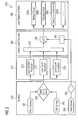
- FIG. 2 shows in accordance with an embodiment of the present invention a block diagram of a load control system 250 for reducing the mechanical load acting on a structural component such as a rotor blade of the respective wind turbine in such a manner that even in extreme wind conditions the wind turbine can be kept in operation.
- the load control system 250 comprises a sensing system 260, an estimating unit 270, a Turbine Load Controller (TLC) 280 and a control unit 290 for executing appropriate mechanical load reduction measures.
- TLC Turbine Load Controller
- the wind turbine load control starts with measuring mechanical loads, which are acting on a structural component of the wind turbine.
- the structural component may be a rotor blade, the nacelle or the tower of the respective load controlled wind turbine.
- the mechanical load measurement may be accomplished with at least one hard sensor 261 such as for instance a force meter, a pressure gauge, a strain gauge (e.g. a tensometer), an acceleration sensor and/or a temperature sensor. Further, the mechanical load measurement may be accomplished with one or more soft sensors 262.
- the signal quality of the sensor signal(s) provided from the hard sensor 261 and/or from the soft sensor 262 is checked with a signal quality control unit 264, which in this document is also called a first receiving unit 264. Thereby, measurement artifacts or apparent measuring errors can be filtered out.
- the described wind turbine load control further comprises measuring the current wind speed. This is accomplished with a wind sensor 266, which outputs an according measurement signal to a second receiving unit 268.
- the second receiving unit 268 may also have the capability of performing a signal quality check of the measurement signal provided by the wind sensor 266.
- a signal being indicative for the current mechanical load acting on the respective structural component is fed from the first receiving unit 264 to the estimation unit 270.
- the estimating unit 270 performs a sophisticated determination of the fatigue life time which the respective structural component has accumulated so far.
- the estimating unit 270 comprises a load condition prediction unit 272, a load cycle detection unit 274 and a load cycle cumulation unit 276.
- the output signal of the first receiving unit 264 is provided both to the load condition prediction unit 272 and to the load cycle detection unit 274.
- the load condition prediction unit 272 predicts the mechanical load condition of the respective structural component and feeds a corresponding signal to a first specifying unit 282 of the TLC 280.
- the load cycle detection unit 274 detects and evaluates the load cycle which is currently acting on the respective structural component and feeds a corresponding signal both to the first specifying unit 282 and to the above mentioned load cycle cumulation unit 276.
- the first specifying unit 282 specifies a current set point value for the fatigue life time consumption of the respective structural component.
- the second receiving provides a wind speed signal being indicative for the current wind speed to a second specifying unit 284.
- the second specifying unit 284 specifies a maximum set point value for the fatigue life time consumption of the structural component based on the signal level of the wind speed signal.
- Both the specified current set point value and the specified maximum set point value are fed to a processing unit 286, which determines an effective set point value for the fatigue life time consumption of the structural component.
- the effective set point value is the smaller value taken from the maximum set point value and the current set point value.
- a control unit 290 selects at least one appropriate load adaptation or load reduction tool.
- load reduction tools or load reduction measures are reducing the rotor speed (reference numeral 290a), adapting the individual blade pitch angle (reference numeral 290b) and/or adjusting the yawing angle (reference numeral 290c). It is mentioned that the given list of load reduction tools is not exclusive. In order to reduce the current mechanical load acting on the structural component a suitable adaptation of any arbitrary parameter of the wind turbine may be carried out, wherein the parameter adaptation typically results in a change of the current power generation of the wind turbine. Therefore, reference numeral 290d indicates other not explicitly described load reduction tools.
- Figures 3a and 3b show diagrams illustrating the determination of an effective set point value for the fatigue life time consumption of a structural component of a wind turbine, wherein the effective set point value depends on the ratio between a wind speed dependent maximum set point value and an accumulated fatigue life time dependent current set point value.
- the solid curve 395 shown in Figures 3a and 3b is the maximum set point value for a fatigue life time consumption of the structural component as a function of the wind velocity V wind .
- Figure 3a illustrates the situation if the wind speed dependent maximum set point value for the fatigue life time consumption of the structural component is larger than the mechanical load dependent current set point value for the fatigue life time consumption of the structural component.
- Figure 3b illustrates the opposite situation, i.e. the wind speed dependent maximum set point value for the fatigue life time consumption of the structural component is smaller than the mechanical load dependent current set point value for the fatigue life time consumption of the structural component.
Priority Applications (4)
| Application Number | Priority Date | Filing Date | Title |
|---|---|---|---|
| EP09014630A EP2325480A1 (de) | 2009-11-24 | 2009-11-24 | Verfahren zur Regelung einer Windturbine sowie Vorrichtung zur Lastregelung einer Windturbine |
| US12/949,853 US20110123331A1 (en) | 2009-11-24 | 2010-11-19 | Wind speed dependent adaptation of a set point for a fatigue life of a structural component of a wind turbine |
| CA2721958A CA2721958A1 (en) | 2009-11-24 | 2010-11-22 | Wind speed dependent adaptation of a set point for a fatigue life of a structural component of a wind turbine |
| CN2010105679542A CN102072085A (zh) | 2009-11-24 | 2010-11-24 | 风力涡轮机结构部件疲劳寿命设定值的风速依赖性适应 |
Applications Claiming Priority (1)
| Application Number | Priority Date | Filing Date | Title |
|---|---|---|---|
| EP09014630A EP2325480A1 (de) | 2009-11-24 | 2009-11-24 | Verfahren zur Regelung einer Windturbine sowie Vorrichtung zur Lastregelung einer Windturbine |
Publications (1)
| Publication Number | Publication Date |
|---|---|
| EP2325480A1 true EP2325480A1 (de) | 2011-05-25 |
Family
ID=42197712
Family Applications (1)
| Application Number | Title | Priority Date | Filing Date |
|---|---|---|---|
| EP09014630A Withdrawn EP2325480A1 (de) | 2009-11-24 | 2009-11-24 | Verfahren zur Regelung einer Windturbine sowie Vorrichtung zur Lastregelung einer Windturbine |
Country Status (4)
| Country | Link |
|---|---|
| US (1) | US20110123331A1 (de) |
| EP (1) | EP2325480A1 (de) |
| CN (1) | CN102072085A (de) |
| CA (1) | CA2721958A1 (de) |
Cited By (14)
| Publication number | Priority date | Publication date | Assignee | Title |
|---|---|---|---|---|
| EP2597302A1 (de) * | 2011-11-23 | 2013-05-29 | Siemens Aktiengesellschaft | Bestimmung einer gesamten Belastung einer Windturbine in Winkelabschnitten |
| WO2013075777A1 (de) * | 2011-11-25 | 2013-05-30 | Robert Bosch Gmbh | Verfahren und recheneinheit zur bestimmung einer gesamtschädigung wenigstens einer rotierenden komponente eines antriebsstrangs |
| EP2599994A1 (de) * | 2011-11-30 | 2013-06-05 | Siemens Aktiengesellschaft | Verfahren zum Betreiben einer Windturbine |
| GB2498458A (en) * | 2012-01-12 | 2013-07-17 | Romax Technology Ltd | Modifying the power output of a wind turbine generator based on fatigue |
| EP2799711A1 (de) * | 2013-05-03 | 2014-11-05 | Alstom Renovables España, S.L. | Verfahren zum Betrieb einer Windturbine |
| EP2821637A1 (de) * | 2013-06-26 | 2015-01-07 | General Electric Company | System und Verfahren zur Steuerung einer Windturbine |
| EP3026587A4 (de) * | 2013-07-22 | 2016-07-27 | Nabla Wind Power S L | Verfahren zur bestimmung der lebensdauer von komponenten einer windturbine oder dergleichen gemäss ihres standorts |
| WO2017000963A1 (en) * | 2015-06-30 | 2017-01-05 | Vestas Wind Systems A/S | Methods and systems for generating wind turbine control schedules |
| WO2017000964A1 (en) * | 2015-06-30 | 2017-01-05 | Vestas Wind Systems A/S | Methods and systems for generating wind turbine control schedules |
| CN107850048A (zh) * | 2015-06-30 | 2018-03-27 | 维斯塔斯风力系统集团公司 | 用于生成风力涡轮机控制安排的方法以及系统 |
| EP3467517A4 (de) * | 2016-09-12 | 2020-02-19 | Korea Aerospace Research Institute | Windrichtungs- und windgeschwindigkeitsmessvorrichtung für windturbine und vorrichtung und verfahren zur steuerung des gierwinkels einer windturbine unter verwendung davon |
| US10928816B2 (en) | 2015-06-30 | 2021-02-23 | Vestas Wind Systems A/S | Methods and systems for generating wind turbine control schedules |
| US11428208B2 (en) | 2015-06-30 | 2022-08-30 | Vestas Wind Systems A/S | Methods and systems for generating wind turbine control schedules |
| WO2024046964A1 (en) * | 2022-08-29 | 2024-03-07 | Siemens Gamesa Renewable Energy A/S | Method of operating a wind turbine |
Families Citing this family (24)
| Publication number | Priority date | Publication date | Assignee | Title |
|---|---|---|---|---|
| DK177434B1 (en) * | 2010-06-18 | 2013-05-21 | Vestas Wind Sys As | Method for controlling a wind turbine |
| DK2463517T3 (da) | 2010-12-08 | 2014-07-21 | Siemens Ag | Fremgangsmåde og styresystem til at reducere vibrationer af et vindenergianlæg |
| EP2557311A1 (de) * | 2011-08-12 | 2013-02-13 | kk-electronic a/s | Verfahren zur Steuerung eines Windkraftparks und durch solch ein Verfahren gesteuerter Windkraftpark |
| US20130204447A1 (en) * | 2012-02-02 | 2013-08-08 | Martin Huus Bjerge | Wind turbine with price-optimised turbine load control |
| US20130259686A1 (en) * | 2012-03-30 | 2013-10-03 | General Electric Company | System and method for controlling a wind turbine |
| ES2700729T3 (es) * | 2013-07-29 | 2019-02-19 | Vestas Wind Sys As | Simulación de una producción de potencia máxima de una turbina eólica |
| DK3055557T3 (da) * | 2013-10-07 | 2019-10-28 | Vestas Wind Sys As | Fremgangsmåder og apparat til styring af vindmøller |
| US9822762B2 (en) * | 2013-12-12 | 2017-11-21 | General Electric Company | System and method for operating a wind turbine |
| ES2813376T3 (es) * | 2014-03-13 | 2021-03-23 | Vestas Wind Sys As | Control de un grupo de turbinas eólicas |
| EP2955368A1 (de) * | 2014-06-10 | 2015-12-16 | ABB Technology AG | Optimaler Windparkbetrieb |
| ES2781599T3 (es) * | 2014-11-24 | 2020-09-03 | Vestas Wind Sys As | Determinación de configuración de turbina eólica |
| US10927814B2 (en) | 2015-06-30 | 2021-02-23 | Vestas Wind Systems A/S | Control method and system for protection of wind turbines |
| US10746160B2 (en) * | 2015-06-30 | 2020-08-18 | Vestas Wind Systems A/S | Methods and systems for generating wind turbine control schedules |
| DK201570559A1 (en) * | 2015-08-28 | 2017-03-27 | Vestas Wind Sys As | Methods and Systems for Generating Wind Turbine Control Schedules |
| US10247170B2 (en) | 2016-06-07 | 2019-04-02 | General Electric Company | System and method for controlling a dynamic system |
| US10544700B2 (en) * | 2016-08-31 | 2020-01-28 | General Electric Technology Gmbh | Advanced startup counter module for a valve and actuator monitoring system |
| EP3607200B1 (de) | 2017-04-06 | 2021-05-05 | Vestas Wind Systems A/S | Verfahren zum nachrüsten einer windenergieanlage mit einer energieerzeugenden einheit |
| ES2946538T3 (es) * | 2017-12-12 | 2023-07-20 | Gen Electric | Procedimientos para hacer funcionar una turbina eólica |
| CN108869173B (zh) * | 2018-01-31 | 2019-08-16 | 北京金风科创风电设备有限公司 | 风电机组的功率控制方法和设备 |
| CN110206682B (zh) * | 2018-02-28 | 2020-06-26 | 北京金风科创风电设备有限公司 | 动态确定偏航控制精度的方法和装置 |
| EP3677772B1 (de) * | 2019-01-02 | 2022-09-21 | Vestas Wind Systems A/S | Verfahren zum betreiben einer windturbine basierend auf der maximalen schubgrenze |
| US11488420B2 (en) * | 2019-05-30 | 2022-11-01 | Board af Supervisors af Louisiana State University and Agricultural and Mechanical College | Damage assessment |
| EP4062053A1 (de) * | 2019-11-21 | 2022-09-28 | Vestas Wind Systems A/S | Verfahren zum nachrüsten einer windturbine |
| WO2023077263A1 (en) * | 2021-11-02 | 2023-05-11 | General Electric Renovables Espana, S.L. | Systems and methods for optimizing wind turbine performance during noise reduced operation |
Citations (6)
| Publication number | Priority date | Publication date | Assignee | Title |
|---|---|---|---|---|
| WO1997009531A1 (de) | 1995-09-01 | 1997-03-13 | Aloys Wobben | Verfahren zum betreiben einer windenergieanlage |
| EP1132614A2 (de) * | 2000-03-09 | 2001-09-12 | Enron Wind GmbH | Regelungssystem für eine Windkraftanlage |
| US20040057828A1 (en) * | 2002-09-23 | 2004-03-25 | Bosche John Vanden | Wind turbine blade deflection control system |
| JP2006241981A (ja) | 2005-02-28 | 2006-09-14 | Mitsubishi Heavy Ind Ltd | 風車の運転制御装置及びその方法並びにプログラム |
| EP1911968A1 (de) * | 2006-10-10 | 2008-04-16 | Ecotecnia Energias Renovables S.L. | Regelungssystem für eine Windenergieanlage sowie Verfahren hierzu |
| US7476985B2 (en) | 2005-07-22 | 2009-01-13 | Gamesa Innovation & Technology, S.L. | Method of operating a wind turbine |
Family Cites Families (8)
| Publication number | Priority date | Publication date | Assignee | Title |
|---|---|---|---|---|
| US20080101930A1 (en) * | 2002-09-23 | 2008-05-01 | Bosche John V | Wind turbine blade deflection control system |
| EP1653050A1 (de) * | 2004-10-29 | 2006-05-03 | Siemens Aktiengesellschaft | Verfahren zur Ermittlung eines für den Ermüdungszustand eines Bauteils charakteristischen Kennwert |
| US8649911B2 (en) * | 2005-06-03 | 2014-02-11 | General Electric Company | System and method for operating a wind farm under high wind speed conditions |
| US7351033B2 (en) * | 2005-09-09 | 2008-04-01 | Mcnerney Gerald | Wind turbine load control method |
| BRPI0717277A2 (pt) * | 2006-10-02 | 2013-01-15 | Clipper Windpower Technology | turbina de vento com controle de passo de pÁ para compensar cisalhamento eàlico e desalinhamento eàlico |
| US8240990B2 (en) * | 2007-12-06 | 2012-08-14 | General Electric Company | Apparatus and method for reducing asymmetric rotor loads in wind turbines during shutdown |
| EP2108830B1 (de) * | 2008-01-10 | 2019-08-28 | Siemens Gamesa Renewable Energy A/S | Verfahren zur Bestimmung der Ermüdungslast einer Windturbine und zur Ermüdungslaststeuerung sowie entsprechende Windturbinen |
| US8328514B2 (en) * | 2009-09-11 | 2012-12-11 | General Electric Company | System and methods for determining a monitor set point limit for a wind turbine |
-
2009
- 2009-11-24 EP EP09014630A patent/EP2325480A1/de not_active Withdrawn
-
2010
- 2010-11-19 US US12/949,853 patent/US20110123331A1/en not_active Abandoned
- 2010-11-22 CA CA2721958A patent/CA2721958A1/en not_active Abandoned
- 2010-11-24 CN CN2010105679542A patent/CN102072085A/zh active Pending
Patent Citations (6)
| Publication number | Priority date | Publication date | Assignee | Title |
|---|---|---|---|---|
| WO1997009531A1 (de) | 1995-09-01 | 1997-03-13 | Aloys Wobben | Verfahren zum betreiben einer windenergieanlage |
| EP1132614A2 (de) * | 2000-03-09 | 2001-09-12 | Enron Wind GmbH | Regelungssystem für eine Windkraftanlage |
| US20040057828A1 (en) * | 2002-09-23 | 2004-03-25 | Bosche John Vanden | Wind turbine blade deflection control system |
| JP2006241981A (ja) | 2005-02-28 | 2006-09-14 | Mitsubishi Heavy Ind Ltd | 風車の運転制御装置及びその方法並びにプログラム |
| US7476985B2 (en) | 2005-07-22 | 2009-01-13 | Gamesa Innovation & Technology, S.L. | Method of operating a wind turbine |
| EP1911968A1 (de) * | 2006-10-10 | 2008-04-16 | Ecotecnia Energias Renovables S.L. | Regelungssystem für eine Windenergieanlage sowie Verfahren hierzu |
Cited By (28)
| Publication number | Priority date | Publication date | Assignee | Title |
|---|---|---|---|---|
| US8511182B2 (en) | 2011-11-23 | 2013-08-20 | Siemens Aktiengesellschaft | Determining an accumulated load of a wind turbine in angular sectors |
| EP2597302A1 (de) * | 2011-11-23 | 2013-05-29 | Siemens Aktiengesellschaft | Bestimmung einer gesamten Belastung einer Windturbine in Winkelabschnitten |
| WO2013075777A1 (de) * | 2011-11-25 | 2013-05-30 | Robert Bosch Gmbh | Verfahren und recheneinheit zur bestimmung einer gesamtschädigung wenigstens einer rotierenden komponente eines antriebsstrangs |
| CN104093976A (zh) * | 2011-11-25 | 2014-10-08 | 罗伯特·博世有限公司 | 用于确定驱动链的至少一个旋转部件的总受损程度的方法和计算单元 |
| US9810203B2 (en) | 2011-11-25 | 2017-11-07 | Zf Friedrichshafen Ag | Method and calculator unit for determining total damage to at least one rotating component of a drive train |
| US9683550B2 (en) | 2011-11-30 | 2017-06-20 | Siemens Aktiengesellschaft | Method for operating a wind turbine |
| EP2599994A1 (de) * | 2011-11-30 | 2013-06-05 | Siemens Aktiengesellschaft | Verfahren zum Betreiben einer Windturbine |
| GB2498458A (en) * | 2012-01-12 | 2013-07-17 | Romax Technology Ltd | Modifying the power output of a wind turbine generator based on fatigue |
| US10584680B2 (en) | 2012-01-12 | 2020-03-10 | Insight Analytics Solutions Holdings Limited | Method for operating a wind turbine generator |
| EP2802772B1 (de) | 2012-01-12 | 2019-08-28 | Insight Analytics Solutions Holdings Limited | Verfahren zum betreiben eines windturbinengenerators |
| GB2498458B (en) * | 2012-01-12 | 2016-03-16 | Romax Technology Ltd | Method for operating a wind turbine generator |
| US9702345B2 (en) | 2013-05-03 | 2017-07-11 | Alstom Renewable Technologies | Method of operating a wind turbine |
| EP2799711A1 (de) * | 2013-05-03 | 2014-11-05 | Alstom Renovables España, S.L. | Verfahren zum Betrieb einer Windturbine |
| EP2821637A1 (de) * | 2013-06-26 | 2015-01-07 | General Electric Company | System und Verfahren zur Steuerung einer Windturbine |
| US9551321B2 (en) | 2013-06-26 | 2017-01-24 | General Electric Company | System and method for controlling a wind turbine |
| EP3026587A4 (de) * | 2013-07-22 | 2016-07-27 | Nabla Wind Power S L | Verfahren zur bestimmung der lebensdauer von komponenten einer windturbine oder dergleichen gemäss ihres standorts |
| EP3575985A1 (de) * | 2013-07-22 | 2019-12-04 | Nabla Wind Power, S.L. | Verfahren zur bestimmung der lebensdauer von komponenten einer windturbine oder dergleichen gemäss ihres standorts |
| US10928816B2 (en) | 2015-06-30 | 2021-02-23 | Vestas Wind Systems A/S | Methods and systems for generating wind turbine control schedules |
| CN107850048A (zh) * | 2015-06-30 | 2018-03-27 | 维斯塔斯风力系统集团公司 | 用于生成风力涡轮机控制安排的方法以及系统 |
| CN107850048B (zh) * | 2015-06-30 | 2020-02-07 | 维斯塔斯风力系统集团公司 | 用于生成风力涡轮机控制安排的方法以及系统 |
| WO2017000963A1 (en) * | 2015-06-30 | 2017-01-05 | Vestas Wind Systems A/S | Methods and systems for generating wind turbine control schedules |
| US10871146B2 (en) | 2015-06-30 | 2020-12-22 | Vestas Wind Systems A/S | Methods and systems for generating wind turbine control schedules |
| WO2017000964A1 (en) * | 2015-06-30 | 2017-01-05 | Vestas Wind Systems A/S | Methods and systems for generating wind turbine control schedules |
| US10975844B2 (en) | 2015-06-30 | 2021-04-13 | Vestas Wind Systems A/S | Methods and systems for generating wind turbine control schedules |
| US11428208B2 (en) | 2015-06-30 | 2022-08-30 | Vestas Wind Systems A/S | Methods and systems for generating wind turbine control schedules |
| EP3467517A4 (de) * | 2016-09-12 | 2020-02-19 | Korea Aerospace Research Institute | Windrichtungs- und windgeschwindigkeitsmessvorrichtung für windturbine und vorrichtung und verfahren zur steuerung des gierwinkels einer windturbine unter verwendung davon |
| US10767635B2 (en) | 2016-09-12 | 2020-09-08 | Korea Aerospace Research Institute | Wind direction and wind velocity measuring apparatus for wind turbine, and device and method for controlling yaw angle of wind turbine by using same |
| WO2024046964A1 (en) * | 2022-08-29 | 2024-03-07 | Siemens Gamesa Renewable Energy A/S | Method of operating a wind turbine |
Also Published As
| Publication number | Publication date |
|---|---|
| US20110123331A1 (en) | 2011-05-26 |
| CA2721958A1 (en) | 2011-05-24 |
| CN102072085A (zh) | 2011-05-25 |
Similar Documents
| Publication | Publication Date | Title |
|---|---|---|
| EP2325480A1 (de) | Verfahren zur Regelung einer Windturbine sowie Vorrichtung zur Lastregelung einer Windturbine | |
| EP2302208A1 (de) | Dynamische Anpassung eines Sollwerts für die Ermüdungslebensdauer einer Strukturkomponente einer Energieerzeugungsmaschine | |
| EP2302206A1 (de) | Auswählen einer Lastverringerungsmaßnahme für den Betrieb einer Energieerzeugungsmaschine | |
| EP3317518B1 (de) | Windturbinensteuerung auf der basis von prognosen | |
| CN107850044B (zh) | 用于风力涡轮机的保护的控制方法和系统 | |
| JP5318454B2 (ja) | 風力タービンの運転方法及び風力タービン | |
| EP3317519B1 (de) | Steuerungsverfahren und -system für windturbinen | |
| EP2302207A1 (de) | Laststeuerung von Energieerzeugungsmaschinen basierend auf der abgelaufenen Ermüdungslebensdauer und der Echtzeit des Betriebs einer Strukturkomponente | |
| EP2056210B1 (de) | Windenergieanlage und Verfahren zur Steuerung einer Windenergieanlage | |
| EP2795109B1 (de) | Steuerverfahren für eine windturbine und windturbine | |
| EP2365215B1 (de) | Drehzahlsteuerung einer Windturbine basierend auf der Rotorbeschleunigung | |
| US20070018457A1 (en) | Method of operating a wind turbine | |
| US20130259686A1 (en) | System and method for controlling a wind turbine | |
| EP2444659A1 (de) | Verfahren und System zur Einstellung eines Betriebsparameters für eine Windturbine | |
| CN107709760B (zh) | 风力涡轮机控制超驰 | |
| US8807937B2 (en) | Wind turbine | |
| WO2012136277A1 (en) | Proactive control of the operation of a wind turbine | |
| DK2659135T3 (en) | System, device and method for adjusting work load of wind turbine component | |
| EP3623615A1 (de) | Reaktion auf ein überdrehzahlereignis |
Legal Events
| Date | Code | Title | Description |
|---|---|---|---|
| PUAI | Public reference made under article 153(3) epc to a published international application that has entered the european phase |
Free format text: ORIGINAL CODE: 0009012 |
|
| AK | Designated contracting states |
Kind code of ref document: A1 Designated state(s): AT BE BG CH CY CZ DE DK EE ES FI FR GB GR HR HU IE IS IT LI LT LU LV MC MK MT NL NO PL PT RO SE SI SK SM TR |
|
| AX | Request for extension of the european patent |
Extension state: AL BA RS |
|
| 17P | Request for examination filed |
Effective date: 20111123 |
|
| RAP1 | Party data changed (applicant data changed or rights of an application transferred) |
Owner name: SIEMENS AKTIENGESELLSCHAFT |
|
| RAP1 | Party data changed (applicant data changed or rights of an application transferred) |
Owner name: SIEMENS AKTIENGESELLSCHAFT |
|
| 17Q | First examination report despatched |
Effective date: 20170907 |
|
| STAA | Information on the status of an ep patent application or granted ep patent |
Free format text: STATUS: THE APPLICATION IS DEEMED TO BE WITHDRAWN |
|
| 18D | Application deemed to be withdrawn |
Effective date: 20180118 |