EP3317236B1 - Methods for producing propylene - Google Patents
Methods for producing propylene Download PDFInfo
- Publication number
- EP3317236B1 EP3317236B1 EP16738271.2A EP16738271A EP3317236B1 EP 3317236 B1 EP3317236 B1 EP 3317236B1 EP 16738271 A EP16738271 A EP 16738271A EP 3317236 B1 EP3317236 B1 EP 3317236B1
- Authority
- EP
- European Patent Office
- Prior art keywords
- cracking
- butene
- stream
- metathesis
- catalyst
- Prior art date
- Legal status (The legal status is an assumption and is not a legal conclusion. Google has not performed a legal analysis and makes no representation as to the accuracy of the status listed.)
- Active
Links
- QQONPFPTGQHPMA-UHFFFAOYSA-N propylene Natural products CC=C QQONPFPTGQHPMA-UHFFFAOYSA-N 0.000 title claims description 130
- 125000004805 propylene group Chemical group [H]C([H])([H])C([H])([*:1])C([H])([H])[*:2] 0.000 title claims description 125
- 238000000034 method Methods 0.000 title claims description 70
- 239000003054 catalyst Substances 0.000 claims description 194
- VYPSYNLAJGMNEJ-UHFFFAOYSA-N Silicium dioxide Chemical compound O=[Si]=O VYPSYNLAJGMNEJ-UHFFFAOYSA-N 0.000 claims description 181
- VXNZUUAINFGPBY-UHFFFAOYSA-N 1-Butene Chemical compound CCC=C VXNZUUAINFGPBY-UHFFFAOYSA-N 0.000 claims description 161
- 238000005649 metathesis reaction Methods 0.000 claims description 154
- IAQRGUVFOMOMEM-UHFFFAOYSA-N butene Natural products CC=CC IAQRGUVFOMOMEM-UHFFFAOYSA-N 0.000 claims description 135
- 238000005336 cracking Methods 0.000 claims description 112
- 239000007795 chemical reaction product Substances 0.000 claims description 107
- 239000000377 silicon dioxide Substances 0.000 claims description 90
- 239000000203 mixture Substances 0.000 claims description 64
- 230000008569 process Effects 0.000 claims description 61
- 239000000047 product Substances 0.000 claims description 53
- 239000011148 porous material Substances 0.000 claims description 48
- 229910044991 metal oxide Inorganic materials 0.000 claims description 35
- 150000004706 metal oxides Chemical class 0.000 claims description 35
- 238000009826 distribution Methods 0.000 claims description 32
- 239000006260 foam Substances 0.000 claims description 14
- 239000003795 chemical substances by application Substances 0.000 claims description 7
- 229910052680 mordenite Inorganic materials 0.000 claims description 7
- 229920001400 block copolymer Polymers 0.000 claims description 5
- 238000011144 upstream manufacturing Methods 0.000 claims description 5
- ZOKXTWBITQBERF-UHFFFAOYSA-N Molybdenum Chemical compound [Mo] ZOKXTWBITQBERF-UHFFFAOYSA-N 0.000 claims description 4
- 229910052750 molybdenum Inorganic materials 0.000 claims description 4
- 239000011733 molybdenum Substances 0.000 claims description 4
- 229910052702 rhenium Inorganic materials 0.000 claims description 4
- WUAPFZMCVAUBPE-UHFFFAOYSA-N rhenium atom Chemical compound [Re] WUAPFZMCVAUBPE-UHFFFAOYSA-N 0.000 claims description 4
- WFKWXMTUELFFGS-UHFFFAOYSA-N tungsten Chemical compound [W] WFKWXMTUELFFGS-UHFFFAOYSA-N 0.000 claims description 4
- 229910052721 tungsten Inorganic materials 0.000 claims description 4
- 239000010937 tungsten Substances 0.000 claims description 4
- LYCAIKOWRPUZTN-UHFFFAOYSA-N Ethylene glycol Chemical group OCCO LYCAIKOWRPUZTN-UHFFFAOYSA-N 0.000 claims description 2
- 229920000463 Poly(ethylene glycol)-block-poly(propylene glycol)-block-poly(ethylene glycol) Polymers 0.000 claims description 2
- 238000012546 transfer Methods 0.000 description 139
- OFBQJSOFQDEBGM-UHFFFAOYSA-N Pentane Chemical compound CCCCC OFBQJSOFQDEBGM-UHFFFAOYSA-N 0.000 description 86
- 238000006243 chemical reaction Methods 0.000 description 76
- VLKZOEOYAKHREP-UHFFFAOYSA-N n-Hexane Chemical compound CCCCCC VLKZOEOYAKHREP-UHFFFAOYSA-N 0.000 description 62
- IJDNQMDRQITEOD-UHFFFAOYSA-N n-butane Chemical compound CCCC IJDNQMDRQITEOD-UHFFFAOYSA-N 0.000 description 57
- ATUOYWHBWRKTHZ-UHFFFAOYSA-N Propane Chemical compound CCC ATUOYWHBWRKTHZ-UHFFFAOYSA-N 0.000 description 52
- 238000000926 separation method Methods 0.000 description 52
- YWAKXRMUMFPDSH-UHFFFAOYSA-N pentene Chemical compound CCCC=C YWAKXRMUMFPDSH-UHFFFAOYSA-N 0.000 description 47
- VGGSQFUCUMXWEO-UHFFFAOYSA-N Ethene Chemical compound C=C VGGSQFUCUMXWEO-UHFFFAOYSA-N 0.000 description 45
- 239000005977 Ethylene Substances 0.000 description 45
- 239000001273 butane Substances 0.000 description 42
- VQTUBCCKSQIDNK-UHFFFAOYSA-N Isobutene Chemical compound CC(C)=C VQTUBCCKSQIDNK-UHFFFAOYSA-N 0.000 description 40
- 235000013844 butane Nutrition 0.000 description 39
- BKOOMYPCSUNDGP-UHFFFAOYSA-N 2-methylbut-2-ene Chemical compound CC=C(C)C BKOOMYPCSUNDGP-UHFFFAOYSA-N 0.000 description 32
- 238000004088 simulation Methods 0.000 description 30
- 239000001294 propane Substances 0.000 description 26
- 150000001336 alkenes Chemical class 0.000 description 23
- IAQRGUVFOMOMEM-ARJAWSKDSA-N cis-but-2-ene Chemical compound C\C=C/C IAQRGUVFOMOMEM-ARJAWSKDSA-N 0.000 description 22
- IAQRGUVFOMOMEM-ONEGZZNKSA-N trans-but-2-ene Chemical compound C\C=C\C IAQRGUVFOMOMEM-ONEGZZNKSA-N 0.000 description 22
- IMNFDUFMRHMDMM-UHFFFAOYSA-N N-Heptane Chemical compound CCCCCCC IMNFDUFMRHMDMM-UHFFFAOYSA-N 0.000 description 20
- 239000000126 substance Substances 0.000 description 19
- ZGEGCLOFRBLKSE-UHFFFAOYSA-N methylene hexane Natural products CCCCCC=C ZGEGCLOFRBLKSE-UHFFFAOYSA-N 0.000 description 18
- -1 polypropylene, propylene Polymers 0.000 description 18
- QMMOXUPEWRXHJS-HWKANZROSA-N (e)-pent-2-ene Chemical compound CC\C=C\C QMMOXUPEWRXHJS-HWKANZROSA-N 0.000 description 17
- QMMOXUPEWRXHJS-HYXAFXHYSA-N (z)-pent-2-ene Chemical compound CC\C=C/C QMMOXUPEWRXHJS-HYXAFXHYSA-N 0.000 description 17
- MHNNAWXXUZQSNM-UHFFFAOYSA-N 2-methylbut-1-ene Chemical compound CCC(C)=C MHNNAWXXUZQSNM-UHFFFAOYSA-N 0.000 description 17
- YHQXBTXEYZIYOV-UHFFFAOYSA-N 3-methylbut-1-ene Chemical compound CC(C)C=C YHQXBTXEYZIYOV-UHFFFAOYSA-N 0.000 description 17
- QMMOXUPEWRXHJS-UHFFFAOYSA-N pentene-2 Natural products CCC=CC QMMOXUPEWRXHJS-UHFFFAOYSA-N 0.000 description 17
- 125000004836 hexamethylene group Chemical class [H]C([H])([*:2])C([H])([H])C([H])([H])C([H])([H])C([H])([H])C([H])([H])[*:1] 0.000 description 16
- 125000004817 pentamethylene group Chemical class [H]C([H])([*:2])C([H])([H])C([H])([H])C([H])([H])C([H])([H])[*:1] 0.000 description 16
- 239000000470 constituent Substances 0.000 description 15
- LIKMAJRDDDTEIG-UHFFFAOYSA-N 1-hexene Chemical compound CCCCC=C LIKMAJRDDDTEIG-UHFFFAOYSA-N 0.000 description 12
- OTMSDBZUPAUEDD-UHFFFAOYSA-N Ethane Chemical compound CC OTMSDBZUPAUEDD-UHFFFAOYSA-N 0.000 description 12
- 150000001335 aliphatic alkanes Chemical class 0.000 description 11
- 238000004519 manufacturing process Methods 0.000 description 11
- 239000003607 modifier Substances 0.000 description 11
- 241000183024 Populus tremula Species 0.000 description 9
- 238000010586 diagram Methods 0.000 description 9
- PNEYBMLMFCGWSK-UHFFFAOYSA-N aluminium oxide Inorganic materials [O-2].[O-2].[O-2].[Al+3].[Al+3] PNEYBMLMFCGWSK-UHFFFAOYSA-N 0.000 description 8
- XNMQEEKYCVKGBD-UHFFFAOYSA-N dimethylacetylene Natural products CC#CC XNMQEEKYCVKGBD-UHFFFAOYSA-N 0.000 description 8
- HNPSIPDUKPIQMN-UHFFFAOYSA-N dioxosilane;oxo(oxoalumanyloxy)alumane Chemical compound O=[Si]=O.O=[Al]O[Al]=O HNPSIPDUKPIQMN-UHFFFAOYSA-N 0.000 description 8
- 230000009977 dual effect Effects 0.000 description 8
- VNWKTOKETHGBQD-UHFFFAOYSA-N methane Chemical compound C VNWKTOKETHGBQD-UHFFFAOYSA-N 0.000 description 8
- 239000012535 impurity Substances 0.000 description 7
- 239000006227 byproduct Substances 0.000 description 6
- 230000003197 catalytic effect Effects 0.000 description 6
- 239000013626 chemical specie Substances 0.000 description 6
- 238000010926 purge Methods 0.000 description 6
- 230000000903 blocking effect Effects 0.000 description 5
- 125000000383 tetramethylene group Chemical group [H]C([H])([*:1])C([H])([H])C([H])([H])C([H])([H])[*:2] 0.000 description 5
- 239000010457 zeolite Substances 0.000 description 5
- 229910021536 Zeolite Inorganic materials 0.000 description 4
- 229910000323 aluminium silicate Inorganic materials 0.000 description 4
- 229910052799 carbon Inorganic materials 0.000 description 4
- 239000000376 reactant Substances 0.000 description 4
- OKKJLVBELUTLKV-UHFFFAOYSA-N Methanol Chemical compound OC OKKJLVBELUTLKV-UHFFFAOYSA-N 0.000 description 3
- KAKZBPTYRLMSJV-UHFFFAOYSA-N butadiene group Chemical group C=CC=C KAKZBPTYRLMSJV-UHFFFAOYSA-N 0.000 description 3
- 238000004523 catalytic cracking Methods 0.000 description 3
- 238000005686 cross metathesis reaction Methods 0.000 description 3
- 239000013078 crystal Substances 0.000 description 3
- 238000005516 engineering process Methods 0.000 description 3
- 238000006317 isomerization reaction Methods 0.000 description 3
- 229910052751 metal Inorganic materials 0.000 description 3
- 239000002184 metal Substances 0.000 description 3
- 230000000737 periodic effect Effects 0.000 description 3
- 238000007670 refining Methods 0.000 description 3
- JMMZCWZIJXAGKW-UHFFFAOYSA-N 2-methylpent-2-ene Chemical compound CCC=C(C)C JMMZCWZIJXAGKW-UHFFFAOYSA-N 0.000 description 2
- OKTJSMMVPCPJKN-UHFFFAOYSA-N Carbon Chemical compound [C] OKTJSMMVPCPJKN-UHFFFAOYSA-N 0.000 description 2
- OAICVXFJPJFONN-UHFFFAOYSA-N Phosphorus Chemical compound [P] OAICVXFJPJFONN-UHFFFAOYSA-N 0.000 description 2
- ZLMJMSJWJFRBEC-UHFFFAOYSA-N Potassium Chemical compound [K] ZLMJMSJWJFRBEC-UHFFFAOYSA-N 0.000 description 2
- 125000003118 aryl group Chemical group 0.000 description 2
- 125000004432 carbon atom Chemical group C* 0.000 description 2
- 230000008859 change Effects 0.000 description 2
- 238000012993 chemical processing Methods 0.000 description 2
- 238000004939 coking Methods 0.000 description 2
- 239000012084 conversion product Substances 0.000 description 2
- HGCIXCUEYOPUTN-UHFFFAOYSA-N cyclohexene Chemical compound C1CCC=CC1 HGCIXCUEYOPUTN-UHFFFAOYSA-N 0.000 description 2
- LPIQUOYDBNQMRZ-UHFFFAOYSA-N cyclopentene Chemical compound C1CC=CC1 LPIQUOYDBNQMRZ-UHFFFAOYSA-N 0.000 description 2
- 230000009849 deactivation Effects 0.000 description 2
- 239000006185 dispersion Substances 0.000 description 2
- 238000009472 formulation Methods 0.000 description 2
- 239000000446 fuel Substances 0.000 description 2
- 239000000463 material Substances 0.000 description 2
- 238000002156 mixing Methods 0.000 description 2
- 239000002808 molecular sieve Substances 0.000 description 2
- SYSQUGFVNFXIIT-UHFFFAOYSA-N n-[4-(1,3-benzoxazol-2-yl)phenyl]-4-nitrobenzenesulfonamide Chemical class C1=CC([N+](=O)[O-])=CC=C1S(=O)(=O)NC1=CC=C(C=2OC3=CC=CC=C3N=2)C=C1 SYSQUGFVNFXIIT-UHFFFAOYSA-N 0.000 description 2
- JRZJOMJEPLMPRA-UHFFFAOYSA-N olefin Natural products CCCCCCCC=C JRZJOMJEPLMPRA-UHFFFAOYSA-N 0.000 description 2
- 229910052698 phosphorus Inorganic materials 0.000 description 2
- 239000011574 phosphorus Substances 0.000 description 2
- 229910052700 potassium Inorganic materials 0.000 description 2
- 239000011591 potassium Substances 0.000 description 2
- 229910052761 rare earth metal Inorganic materials 0.000 description 2
- 150000002910 rare earth metals Chemical class 0.000 description 2
- URGAHOPLAPQHLN-UHFFFAOYSA-N sodium aluminosilicate Chemical compound [Na+].[Al+3].[O-][Si]([O-])=O.[O-][Si]([O-])=O URGAHOPLAPQHLN-UHFFFAOYSA-N 0.000 description 2
- ZNOKGRXACCSDPY-UHFFFAOYSA-N tungsten trioxide Chemical group O=[W](=O)=O ZNOKGRXACCSDPY-UHFFFAOYSA-N 0.000 description 2
- GORWESNAYCCILJ-SCBDLNNBSA-N (E)-but-2-ene 2-methylbut-2-ene Chemical compound C\C=C\C.CC=C(C)C GORWESNAYCCILJ-SCBDLNNBSA-N 0.000 description 1
- DYLIWHYUXAJDOJ-OWOJBTEDSA-N (e)-4-(6-aminopurin-9-yl)but-2-en-1-ol Chemical compound NC1=NC=NC2=C1N=CN2C\C=C\CO DYLIWHYUXAJDOJ-OWOJBTEDSA-N 0.000 description 1
- LGAQJENWWYGFSN-SNAWJCMRSA-N (e)-4-methylpent-2-ene Chemical compound C\C=C\C(C)C LGAQJENWWYGFSN-SNAWJCMRSA-N 0.000 description 1
- SMZOUWXMTYCWNB-UHFFFAOYSA-N 2-(2-methoxy-5-methylphenyl)ethanamine Chemical compound COC1=CC=C(C)C=C1CCN SMZOUWXMTYCWNB-UHFFFAOYSA-N 0.000 description 1
- RYPKRALMXUUNKS-UHFFFAOYSA-N 2-Hexene Natural products CCCC=CC RYPKRALMXUUNKS-UHFFFAOYSA-N 0.000 description 1
- NIXOWILDQLNWCW-UHFFFAOYSA-N 2-Propenoic acid Natural products OC(=O)C=C NIXOWILDQLNWCW-UHFFFAOYSA-N 0.000 description 1
- RYPKRALMXUUNKS-HWKANZROSA-N 2E-hexene Chemical compound CCC\C=C\C RYPKRALMXUUNKS-HWKANZROSA-N 0.000 description 1
- 239000004215 Carbon black (E152) Substances 0.000 description 1
- UGFAIRIUMAVXCW-UHFFFAOYSA-N Carbon monoxide Chemical compound [O+]#[C-] UGFAIRIUMAVXCW-UHFFFAOYSA-N 0.000 description 1
- RVGRUAULSDPKGF-UHFFFAOYSA-N Poloxamer Chemical group C1CO1.CC1CO1 RVGRUAULSDPKGF-UHFFFAOYSA-N 0.000 description 1
- 239000004743 Polypropylene Substances 0.000 description 1
- GOOHAUXETOMSMM-UHFFFAOYSA-N Propylene oxide Chemical compound CC1CO1 GOOHAUXETOMSMM-UHFFFAOYSA-N 0.000 description 1
- RTAQQCXQSZGOHL-UHFFFAOYSA-N Titanium Chemical compound [Ti] RTAQQCXQSZGOHL-UHFFFAOYSA-N 0.000 description 1
- 235000010724 Wisteria floribunda Nutrition 0.000 description 1
- 238000005865 alkene metathesis reaction Methods 0.000 description 1
- 238000009835 boiling Methods 0.000 description 1
- 238000010504 bond cleavage reaction Methods 0.000 description 1
- 238000006555 catalytic reaction Methods 0.000 description 1
- ZQDPJFUHLCOCRG-WAYWQWQTSA-N cis-3-hexene Chemical compound CC\C=C/CC ZQDPJFUHLCOCRG-WAYWQWQTSA-N 0.000 description 1
- 238000004891 communication Methods 0.000 description 1
- CFBGXYDUODCMNS-UHFFFAOYSA-N cyclobutene Chemical compound C1CC=C1 CFBGXYDUODCMNS-UHFFFAOYSA-N 0.000 description 1
- 238000006356 dehydrogenation reaction Methods 0.000 description 1
- 230000001627 detrimental effect Effects 0.000 description 1
- 238000004821 distillation Methods 0.000 description 1
- 238000011143 downstream manufacturing Methods 0.000 description 1
- 230000000694 effects Effects 0.000 description 1
- 238000001914 filtration Methods 0.000 description 1
- 239000003546 flue gas Substances 0.000 description 1
- 239000012634 fragment Substances 0.000 description 1
- 229930195733 hydrocarbon Natural products 0.000 description 1
- 150000002430 hydrocarbons Chemical class 0.000 description 1
- 239000001257 hydrogen Substances 0.000 description 1
- 229910052739 hydrogen Inorganic materials 0.000 description 1
- 125000004435 hydrogen atom Chemical class [H]* 0.000 description 1
- 238000001027 hydrothermal synthesis Methods 0.000 description 1
- 238000005470 impregnation Methods 0.000 description 1
- 238000005259 measurement Methods 0.000 description 1
- 239000012528 membrane Substances 0.000 description 1
- 239000002245 particle Substances 0.000 description 1
- RGSFGYAAUTVSQA-UHFFFAOYSA-N pentamethylene Natural products C1CCCC1 RGSFGYAAUTVSQA-UHFFFAOYSA-N 0.000 description 1
- 230000000704 physical effect Effects 0.000 description 1
- 229920001983 poloxamer Polymers 0.000 description 1
- 229920001155 polypropylene Polymers 0.000 description 1
- 238000012545 processing Methods 0.000 description 1
- 230000008929 regeneration Effects 0.000 description 1
- 238000011069 regeneration method Methods 0.000 description 1
- 230000007017 scission Effects 0.000 description 1
- 238000005872 self-metathesis reaction Methods 0.000 description 1
- 238000007086 side reaction Methods 0.000 description 1
- 238000000638 solvent extraction Methods 0.000 description 1
- 241000894007 species Species 0.000 description 1
- 238000004230 steam cracking Methods 0.000 description 1
- 125000001424 substituent group Chemical group 0.000 description 1
- 239000004094 surface-active agent Substances 0.000 description 1
- 229910052719 titanium Inorganic materials 0.000 description 1
- 239000010936 titanium Substances 0.000 description 1
- ZQDPJFUHLCOCRG-AATRIKPKSA-N trans-3-hexene Chemical compound CC\C=C\CC ZQDPJFUHLCOCRG-AATRIKPKSA-N 0.000 description 1
- 238000006276 transfer reaction Methods 0.000 description 1
Images


Classifications
-
- C—CHEMISTRY; METALLURGY
- C07—ORGANIC CHEMISTRY
- C07C—ACYCLIC OR CARBOCYCLIC COMPOUNDS
- C07C6/00—Preparation of hydrocarbons from hydrocarbons containing a different number of carbon atoms by redistribution reactions
- C07C6/02—Metathesis reactions at an unsaturated carbon-to-carbon bond
- C07C6/04—Metathesis reactions at an unsaturated carbon-to-carbon bond at a carbon-to-carbon double bond
-
- B—PERFORMING OPERATIONS; TRANSPORTING
- B01—PHYSICAL OR CHEMICAL PROCESSES OR APPARATUS IN GENERAL
- B01J—CHEMICAL OR PHYSICAL PROCESSES, e.g. CATALYSIS OR COLLOID CHEMISTRY; THEIR RELEVANT APPARATUS
- B01J23/00—Catalysts comprising metals or metal oxides or hydroxides, not provided for in group B01J21/00
- B01J23/16—Catalysts comprising metals or metal oxides or hydroxides, not provided for in group B01J21/00 of arsenic, antimony, bismuth, vanadium, niobium, tantalum, polonium, chromium, molybdenum, tungsten, manganese, technetium or rhenium
- B01J23/24—Chromium, molybdenum or tungsten
- B01J23/30—Tungsten
-
- B—PERFORMING OPERATIONS; TRANSPORTING
- B01—PHYSICAL OR CHEMICAL PROCESSES OR APPARATUS IN GENERAL
- B01J—CHEMICAL OR PHYSICAL PROCESSES, e.g. CATALYSIS OR COLLOID CHEMISTRY; THEIR RELEVANT APPARATUS
- B01J29/00—Catalysts comprising molecular sieves
- B01J29/03—Catalysts comprising molecular sieves not having base-exchange properties
- B01J29/0308—Mesoporous materials not having base exchange properties, e.g. Si-MCM-41
- B01J29/0341—Mesoporous materials not having base exchange properties, e.g. Si-MCM-41 containing arsenic, antimony, bismuth, vanadium, niobium, tantalum, polonium, chromium, molybdenum, tungsten, manganese, technetium or rhenium
-
- B—PERFORMING OPERATIONS; TRANSPORTING
- B01—PHYSICAL OR CHEMICAL PROCESSES OR APPARATUS IN GENERAL
- B01J—CHEMICAL OR PHYSICAL PROCESSES, e.g. CATALYSIS OR COLLOID CHEMISTRY; THEIR RELEVANT APPARATUS
- B01J29/00—Catalysts comprising molecular sieves
- B01J29/03—Catalysts comprising molecular sieves not having base-exchange properties
- B01J29/035—Microporous crystalline materials not having base exchange properties, such as silica polymorphs, e.g. silicalites
-
- B—PERFORMING OPERATIONS; TRANSPORTING
- B01—PHYSICAL OR CHEMICAL PROCESSES OR APPARATUS IN GENERAL
- B01J—CHEMICAL OR PHYSICAL PROCESSES, e.g. CATALYSIS OR COLLOID CHEMISTRY; THEIR RELEVANT APPARATUS
- B01J29/00—Catalysts comprising molecular sieves
- B01J29/04—Catalysts comprising molecular sieves having base-exchange properties, e.g. crystalline zeolites
- B01J29/06—Crystalline aluminosilicate zeolites; Isomorphous compounds thereof
- B01J29/40—Crystalline aluminosilicate zeolites; Isomorphous compounds thereof of the pentasil type, e.g. types ZSM-5, ZSM-8 or ZSM-11, as exemplified by patent documents US3702886, GB1334243 and US3709979, respectively
- B01J29/48—Crystalline aluminosilicate zeolites; Isomorphous compounds thereof of the pentasil type, e.g. types ZSM-5, ZSM-8 or ZSM-11, as exemplified by patent documents US3702886, GB1334243 and US3709979, respectively containing arsenic, antimony, bismuth, vanadium, niobium tantalum, polonium, chromium, molybdenum, tungsten, manganese, technetium or rhenium
-
- B—PERFORMING OPERATIONS; TRANSPORTING
- B01—PHYSICAL OR CHEMICAL PROCESSES OR APPARATUS IN GENERAL
- B01J—CHEMICAL OR PHYSICAL PROCESSES, e.g. CATALYSIS OR COLLOID CHEMISTRY; THEIR RELEVANT APPARATUS
- B01J35/00—Catalysts, in general, characterised by their form or physical properties
- B01J35/19—Catalysts containing parts with different compositions
-
- B—PERFORMING OPERATIONS; TRANSPORTING
- B01—PHYSICAL OR CHEMICAL PROCESSES OR APPARATUS IN GENERAL
- B01J—CHEMICAL OR PHYSICAL PROCESSES, e.g. CATALYSIS OR COLLOID CHEMISTRY; THEIR RELEVANT APPARATUS
- B01J35/00—Catalysts, in general, characterised by their form or physical properties
- B01J35/30—Catalysts, in general, characterised by their form or physical properties characterised by their physical properties
-
- B—PERFORMING OPERATIONS; TRANSPORTING
- B01—PHYSICAL OR CHEMICAL PROCESSES OR APPARATUS IN GENERAL
- B01J—CHEMICAL OR PHYSICAL PROCESSES, e.g. CATALYSIS OR COLLOID CHEMISTRY; THEIR RELEVANT APPARATUS
- B01J35/00—Catalysts, in general, characterised by their form or physical properties
- B01J35/40—Catalysts, in general, characterised by their form or physical properties characterised by dimensions, e.g. grain size
-
- B—PERFORMING OPERATIONS; TRANSPORTING
- B01—PHYSICAL OR CHEMICAL PROCESSES OR APPARATUS IN GENERAL
- B01J—CHEMICAL OR PHYSICAL PROCESSES, e.g. CATALYSIS OR COLLOID CHEMISTRY; THEIR RELEVANT APPARATUS
- B01J35/00—Catalysts, in general, characterised by their form or physical properties
- B01J35/60—Catalysts, in general, characterised by their form or physical properties characterised by their surface properties or porosity
- B01J35/63—Pore volume
- B01J35/635—0.5-1.0 ml/g
-
- B—PERFORMING OPERATIONS; TRANSPORTING
- B01—PHYSICAL OR CHEMICAL PROCESSES OR APPARATUS IN GENERAL
- B01J—CHEMICAL OR PHYSICAL PROCESSES, e.g. CATALYSIS OR COLLOID CHEMISTRY; THEIR RELEVANT APPARATUS
- B01J35/00—Catalysts, in general, characterised by their form or physical properties
- B01J35/60—Catalysts, in general, characterised by their form or physical properties characterised by their surface properties or porosity
- B01J35/64—Pore diameter
- B01J35/647—2-50 nm
-
- B—PERFORMING OPERATIONS; TRANSPORTING
- B01—PHYSICAL OR CHEMICAL PROCESSES OR APPARATUS IN GENERAL
- B01J—CHEMICAL OR PHYSICAL PROCESSES, e.g. CATALYSIS OR COLLOID CHEMISTRY; THEIR RELEVANT APPARATUS
- B01J37/00—Processes, in general, for preparing catalysts; Processes, in general, for activation of catalysts
- B01J37/02—Impregnation, coating or precipitation
- B01J37/0201—Impregnation
-
- C—CHEMISTRY; METALLURGY
- C07—ORGANIC CHEMISTRY
- C07C—ACYCLIC OR CARBOCYCLIC COMPOUNDS
- C07C11/00—Aliphatic unsaturated hydrocarbons
- C07C11/02—Alkenes
- C07C11/06—Propene
-
- C—CHEMISTRY; METALLURGY
- C07—ORGANIC CHEMISTRY
- C07C—ACYCLIC OR CARBOCYCLIC COMPOUNDS
- C07C4/00—Preparation of hydrocarbons from hydrocarbons containing a larger number of carbon atoms
- C07C4/02—Preparation of hydrocarbons from hydrocarbons containing a larger number of carbon atoms by cracking a single hydrocarbon or a mixture of individually defined hydrocarbons or a normally gaseous hydrocarbon fraction
- C07C4/06—Catalytic processes
-
- B—PERFORMING OPERATIONS; TRANSPORTING
- B01—PHYSICAL OR CHEMICAL PROCESSES OR APPARATUS IN GENERAL
- B01J—CHEMICAL OR PHYSICAL PROCESSES, e.g. CATALYSIS OR COLLOID CHEMISTRY; THEIR RELEVANT APPARATUS
- B01J29/00—Catalysts comprising molecular sieves
- B01J29/005—Mixtures of molecular sieves comprising at least one molecular sieve which is not an aluminosilicate zeolite, e.g. from groups B01J29/03 - B01J29/049 or B01J29/82 - B01J29/89
-
- C—CHEMISTRY; METALLURGY
- C07—ORGANIC CHEMISTRY
- C07C—ACYCLIC OR CARBOCYCLIC COMPOUNDS
- C07C2521/00—Catalysts comprising the elements, oxides or hydroxides of magnesium, boron, aluminium, carbon, silicon, titanium, zirconium or hafnium
- C07C2521/06—Silicon, titanium, zirconium or hafnium; Oxides or hydroxides thereof
- C07C2521/08—Silica
-
- C—CHEMISTRY; METALLURGY
- C07—ORGANIC CHEMISTRY
- C07C—ACYCLIC OR CARBOCYCLIC COMPOUNDS
- C07C2523/00—Catalysts comprising metals or metal oxides or hydroxides, not provided for in group C07C2521/00
- C07C2523/16—Catalysts comprising metals or metal oxides or hydroxides, not provided for in group C07C2521/00 of arsenic, antimony, bismuth, vanadium, niobium, tantalum, polonium, chromium, molybdenum, tungsten, manganese, technetium or rhenium
- C07C2523/24—Chromium, molybdenum or tungsten
- C07C2523/30—Tungsten
-
- C—CHEMISTRY; METALLURGY
- C07—ORGANIC CHEMISTRY
- C07C—ACYCLIC OR CARBOCYCLIC COMPOUNDS
- C07C2529/00—Catalysts comprising molecular sieves
- C07C2529/04—Catalysts comprising molecular sieves having base-exchange properties, e.g. crystalline zeolites, pillared clays
- C07C2529/06—Crystalline aluminosilicate zeolites; Isomorphous compounds thereof
- C07C2529/40—Crystalline aluminosilicate zeolites; Isomorphous compounds thereof of the pentasil type, e.g. types ZSM-5, ZSM-8 or ZSM-11
-
- Y—GENERAL TAGGING OF NEW TECHNOLOGICAL DEVELOPMENTS; GENERAL TAGGING OF CROSS-SECTIONAL TECHNOLOGIES SPANNING OVER SEVERAL SECTIONS OF THE IPC; TECHNICAL SUBJECTS COVERED BY FORMER USPC CROSS-REFERENCE ART COLLECTIONS [XRACs] AND DIGESTS
- Y02—TECHNOLOGIES OR APPLICATIONS FOR MITIGATION OR ADAPTATION AGAINST CLIMATE CHANGE
- Y02P—CLIMATE CHANGE MITIGATION TECHNOLOGIES IN THE PRODUCTION OR PROCESSING OF GOODS
- Y02P20/00—Technologies relating to chemical industry
- Y02P20/50—Improvements relating to the production of bulk chemicals
- Y02P20/52—Improvements relating to the production of bulk chemicals using catalysts, e.g. selective catalysts
Definitions
- the present disclosure generally relates to processes and systems for producing propylene, and more specifically, to processes and systems for producing propylene from process streams comprising butene.
- propylene production processes contribute to the total propylene production.
- propane dehydrogenation (PDH) propane dehydrogenation (PDH)
- metathesis reactions requiring both ethylene and butene
- high severity FCC high severity FCC
- olefins cracking olefins cracking
- MTO methanol to olefins
- WO 2010/019595 discloses a process for the production of propylene wherein a hydrocarbon stream is fractionated, following which the heavy C 4 fraction is contacted with a metathesis catalyst and the light C 4 fraction is separately cracked.
- propylene may be produced by a process comprising at least partially metathesizing a first composition comprising at least 10 wt.% butene to form a metathesis-reaction product, where the first composition is metathesized with a metathesis catalyst comprising a mesoporous silica catalyst impregnated with metal oxide, where the mesoporous silica catalyst includes a pore size distribution of 2.5 nm to 40 nm and a total pore volume of at least 0.600 cm 3 /g; at least partially cracking the metathesis-reaction product to form a cracking-reaction product comprising propylene, where the metathesis-reaction product is cracked with a cracking catalyst comprising a mordenite framework inverted (MFI) structured silica catalyst, where the MFI structured silica catalyst includes total acidity of 0.001 mmol/g to 0.1 mmol/g; and at least partially separating propylene from the cracking-reaction product to form
- MFI mordenite framework inverted
- propylene may be produced by a process comprising:
- propylene may be produced by a process comprising:
- the present invention further provides a process for producing polypropylene, the process comprising:
- metathesis catalysts may be utilized which comprises a mesoporous silica catalyst impregnated with metal oxide, where the mesoporous silica catalyst includes a pore size distribution of 2.5 nm to 40 nm and a total pore volume of at least 0.600 cm 3 /g.
- a cracking catalyst may be utilized which comprises a mordenite framework inverted (MFI) structured silica catalyst, where the MFI structured silica catalyst includes total acidity of 0.001 mmol/g to 0.1 mmol/g.
- MFI mordenite framework inverted
- a cracking catalyst may be utilized which comprises an amorphous mesoporous silica foam impregnated with metal oxides, where the metathesis catalyst has a pore size distribution of at least 3 nm to 40 nm and a total pore volume of at least 0.700 cm 3 /g.
- FIGS. 1-4 For the purpose of the simplified schematic illustrations and descriptions of FIGS. 1-4 , the numerous valves, temperature sensors, electronic controllers and the like that may be employed and well known to those of ordinary skill in the art of certain refinery operations are not included. Further, accompanying components that are in conventional refinery operations including catalytic conversion processes such as, for example, air supplies, catalyst hoppers, and flue gas handling are not depicted. However, operational components, such as those described in the present disclosure, may be added to the embodiments described in this disclosure.
- arrows in the drawings refer to transfer lines which may serve to transfer steams between two or more system components. Additionally, arrows that connect to system components define inlets or outlets in each given system component. The arrow direction corresponds generally with the major direction of movement of the materials of the stream contained within the physical transfer line signified by the arrow. Furthermore, arrows which do not connect two or more system components signify a product stream which exits the depicted system or a system inlet stream which enters the depicted system. Product streams may be further processed in accompanying chemical processing systems or may be commercialized as end products. System inlet streams may be streams transferred from accompanying chemical processing systems or may be non-processed feedstock streams.
- the conversion systems include system components which are operable to carry out a method where a stream comprising butene undergoes a metathesis reaction and a cracking reaction to form propylene.
- the metathesis reaction may be followed by the cracking reaction, where the metathesis and cracking reactions may be carried out in separate reactors arranged in series or may be carried out in a single reactor comprising multiple catalysts positioned in different sections of the reactor.
- the product stream may be separated into multiple streams, where some streams may optionally be recycled back into the system.
- a product stream comprising at least 80 wt.% propylene may be produced from the reaction products of the cracking reaction.
- the systems may operate with a single system inlet stream comprising at least 50 wt.% butenes, such as raffinate streams created from a naphtha cracking process.
- the systems generally do not require a system inlet comprising ethylene, and the process is fully functional without ethylene supplied to the system.
- transfer lines may include pipes, conduits, channels, or other suitable physical transfer lines that connect by fluidic communication one or more system components to one or more other system components.
- a “system component” refers to any apparatus included in the system, such as, but not limited to, separation units, reactors, heat transfer devices such as heaters and heat exchangers, filters, impurities removal devices, combinations of each, and the like.
- a transfer line may generally carry a process stream between two or more system components.
- a transfer line may comprise multiple segments, where a "segment" of a transfer line includes one or more portions of a transfer line, such that a transfer line may comprise multiple transfer line segments.
- the chemical composition of a process stream in a particular transfer line is similar or identical throughout the entire length of the transfer line.
- the temperature, pressure, or other physical properties of a process stream may change through a transfer line, particularly in different transfer line segments.
- relatively minor compositional changes in a process stream may take place over the length of a transfer line, such as the removal of an impurity.
- the systems described in this disclosure are referred to as "butene conversion systems,” which refers to any system which at least partially converts butene into one or more other chemical species. For example, in some embodiments, butene is at least partially converted into propylene.
- the butene conversion systems are suitable to process streams comprising butene, including streams that are substantially free of other alkenes (for example, ethylene, propene), into a product process stream comprising a significant amount of propylene.
- a stream or composition does "not substantially comprise” or “is substantially free” of a component when that component is present in an amount of less than 0.1 wt.%.
- a separation unit refers to any separation device that at least partially separates one or more chemicals that are mixed in a process stream from one another.
- a separation unit may selectively separate differing chemical species from one another, forming one or more chemical fractions.
- separation units include, without limitation, distillation columns, flash drums, knock-out drums, knock-out pots, centrifuges, filtration devices, traps, scrubbers, expansion devices, membranes, solvent extraction devices, and the like. It should be understood that separation processes described in this disclosure may not completely separate all of one chemical consistent from all of another chemical constituent.
- separation processes described in this disclosure "at least partially" separate different chemical components from one another, and that even if not explicitly stated, it should be understood that separation may include only partial separation.
- one or more chemical constituents may be "separated” from a process stream to form a new process stream.
- a process stream may enter a separation unit and be divided, or separated, into two or more process streams of desired composition.
- a "light fraction” and a “heavy fraction” may exit the separation unit, where, in general, the light fraction stream has a lesser boiling point than the heavy fraction stream.
- a reactor refers to a vessel in which one or more chemical reactions may occur between one or more reactants optionally in the presence of one or more catalysts.
- a reactor may include a tank or tubular reactor configured to operate as a batch reactor, a continuous stirred-tank reactor (CSTR), or a plug flow reactor.
- Example reactors include packed bed reactors such as fixed bed reactors, and fluidized bed reactors.
- a reactor may comprise one or more catalyst sections, such as catalyst beds, where a "section” is the area of the reactor which houses a particular catalyst or group of multiple catalysts.
- separation and reactions may take place in a reactive separation unit.
- a "catalyst” refers to any substance which increases the rate of a specific chemical reaction. Catalysts described in this disclosure may be utilized to promote various reactions, such as, but not limited to, metathesis or cracking reactions, or both.
- a “metathesis catalyst” increases the rate of a metathesis reaction
- a “cracking catalyst” increases the rate of a cracking reaction.
- metalathesis generally refers to a chemical reaction where fragments of alkenes (olefins) are redistributed by the scission and regeneration of alkene bonds.
- cracking generally refers to a chemical reaction where a molecule having carbon to carbon bonds is broken into more than one molecule by the breaking of one or more of the carbon to carbon bonds.
- the resulting cracked molecules may have combined the same number of carbon atoms as the original molecule prior to cracking.
- metathesis catalysts and cracking catalysts are disclosed in co-pending Saudi Aramco U.S. Provisional Patent Application No. 62/188,178 entitled “Dual Catalyst System for Propylene Production” (Attorney Docket SA 6019 MA) and co-pending Saudi Aramco U.S. Provisional Patent Application No. 62/188,129 entitled “Propylene Production Using a Mesoporous Silica Foam Metathesis Catalyst" (Attorney Docket SA 6016 MA).
- suitable metathesis catalysts may include mesoporous silica catalysts impregnated with metal oxide.
- Suitable cracking catalysts may include mordenite framework inverted (MFI) structured silica catalysts.
- the mesoporous silica catalysts may include a pore size distribution of from 2.5 nm to 40 nm and a total pore volume of at least 0.600 cm 3 /g (cubic centimeters per gram).
- the systems described in this disclosure may include any suitable metathesis catalysts and cracking catalysts, such as commercially available catalysts or catalysts which are the subject of future discovery.
- the suitable reaction conditions for metathesis and cracking reactions described in this disclosure may vary by the catalyst compositions employed. However, in some embodiments, the metathesis or cracking reactions, or both, may take place at temperatures from 500 °C (degrees Celsius) to 600 °C in atmospheric pressure.
- butene may include at least 1-butene, isobutene, cis-2-butene, trans-2-butene 2-methyl-2-butene, 3-methyl-1-butene, 2-methyl-1-butene, and cyclobutene.
- Butene is sometimes referred to as butylene, and the terms “butene” and “butylene” may be used interchangeably in this disclosure.
- pentene may include at least 1-pentene, cis-2-pentene, trans-2-pentene, 4-methyl-trans-2-pentene, cyclopentene, and 2-methyl-2-pentene.
- hexene may include at least trans-2-hexene, trans-3-hexene, cis-3-hexene, and cyclohexene.
- Mixing or combining may also include mixing by directly introducing both streams into a like reactor, separation device, or other system component.
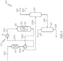
- a butene conversion system may comprise a dual catalyst reactor where metathesis and cracking reactions occur in a single reactor, described subsequently with reference to FIGS. 1 .
- a stream comprising butene enters the system and undergoes a metathesis reaction, followed by a cracking reaction, in a single reactor.
- the reactor contains a metathesis catalyst section upstream of a cracking catalyst section.
- the product stream of the cracking reaction comprises propylene and a product stream comprising propylene may be separated from the product stream of the cracking reaction.
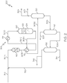
- FIG. 2 is similar to that of FIG. 1 , but comprises a recycle stream.
- the recycle stream of FIG. 2 may comprise butane and butene and be mixed with the inlet stream comprising butene.
- the stream entering the reactor of FIG. 2 may thereby generally contain a greater percentage of butane than that of the embodiment of FIG. 1 .
- a butene conversion system may comprise multiple reactors in series where metathesis and cracking reactions occur in separate reactors, as described subsequently with reference to FIGS. 3 and 4 .
- the embodiment of FIG. 3 is similar to that of FIG. 1 , but comprises reactors in series in which the metathesis and cracking reactions take place.
- the stream compositions of FIGS. 1 and 3 may be similar or identical relative to like inlet streams and reaction rates.
- the embodiment of FIG. 4 is similar to that of FIG. 3 , but comprises a recycle stream.
- the recycle stream of FIG. 4 may comprise butane and butene and may be mixed with the metathesis-reaction product between the metathesis and cracking reactors.
- FIGS. 1-4 may have varying mechanical apparatus or process stream compositions, or both, these embodiments generally share many of the same system components and transfer lines.
- processes which occur in like system components in the various embodiments of FIGS. 1-4 may be similar or identical with one another.
- the system components of FIGS. 1-4 marked with the same reference number may perform similar or identical operations in the various embodiments.
- Some process streams in the embodiments of FIGS. 1-4 may comprise similar or identical compositions, while others may not.
- the transfer lines of the embodiments of FIGS. 1-4 have each been given different reference numbers so that the composition of their contained stream may be easily identified.
- some transfer lines may be in like areas and have like functions in the various embodiments of FIGS.
- FIGS. 1-4 they may have substantially different compositions (such as in cases where recycle streams are present or where recycle streams reenter at differing system locations). Some process streams contained in like areas of FIGS. 1-4 may be similar or even identical in like processing conditions (for example, like inlet stream composition).
- the streams of transfer lines/segments such as, but not limited to: 201A, 310, 401A, and 501A may be similar or substantially identical in composition; 204, 304, 404, and 504 may be similar or substantially identical in composition; 205, 305, 405, and 505 may be similar or substantially identical in composition; 207, 307, 407, and 507 may be similar or substantially identical in composition; 203 and 403 may be similar or substantially identical in composition; 206 and 406 may be similar or substantially identical in composition; 208 and 408 may be similar or substantially identical in composition.
- the Examples, as provided in this disclosure, will help to further clarify the differences in process stream compositions between the various embodiments.
- a butene conversion system 100 may include a metathesis/cracking reactor 120 which comprises a metathesis catalyst section 122 and a cracking catalyst section 124.
- a system inlet stream comprising butene enters the butene conversion system 100 through a transfer line 201 (including segments 201A, 201B, 201C, and 201D) and is injected into the metathesis/cracking reactor 120.
- the system inlet stream of segment 201A generally comprises at least butene, and may optionally comprise other chemical species such as butane.
- the system inlet stream may comprise at least 20 wt.%, 30 wt.%, 40 wt.%, 50 wt.%, 55 wt.%, 60 wt.%, 65 wt.%, or even at least 70 wt.% butene.
- the system inlet stream may comprise at least 15 wt.%, 20 wt.%, 25 wt.%, 30 wt.%, or even at least 35 wt.% butane.
- the system inlet stream may comprise from 0 wt.% to 10 wt.%, 8 wt.%, 4 wt.%, 2 wt.%, or 1 wt.% ethylene, or may not substantially comprise ethylene.
- the system inlet stream may be processed by one or more system components prior to entering the metathesis/cracking reactor 120.
- the transfer line 201 may comprise several segments (depicted as 201A, 201B, 201C, and 201D) which may be separated by system components such as an impurities removal device 110, heat transfer device 112, and heat transfer device 114.
- the impurities removal device 110 may remove oxygenates present in the system inlet stream.
- the impurities removal device 110 comprises a catalytic bed.
- Heat transfer device 112 may be a heat exchanger that serves to elevate the temperature of the system inlet stream by exchanging energy with the stream present in transfer line 203A.
- Heat transfer device 114 may be a heater that serves to further heat the system inlet stream.
- the impurities removal device 110, heat transfer device 112, and heat transfer device 114 are optional components in the butene conversion system 100. It should be understood that all streams located in the various segments of transfer line 201 (that is, 201A, 201B, 201C, and 201D) are considered portions of the system inlet stream, even though the chemical composition, temperature, or other properties of the system inlet stream may be different in the various segments 201A, 201B, 201C, 201D.
- the metathesis/cracking reactor 120 comprises a metathesis catalyst section 122 and a cracking catalyst section 124.
- the metathesis catalyst section 122 is positioned generally upstream of the cracking catalyst section 124, that is, the cracking catalyst section 124 is positioned generally downstream of the metathesis catalyst section 122.
- the system inlet stream from segment 201D enters the metathesis/cracking reactor 120 and contacts the metathesis catalyst to undergo a metathesis reaction in the metathesis catalyst section 122 to form a metathesis-reaction product.
- the metathesis-reaction product is contacted with the cracking catalyst to undergo cracking a cracking reaction in the cracking catalyst section 124.
- the cracking reaction forms a cracking-reaction product.
- the reactants that undergo cracking or metathesis, or both intimately intermingle with the respective catalysts during reaction.
- a "metathesis-reaction product” refers to the entire product mixture resulting from the metathesis reaction, including any portion of the product mixture which does not undergo metathesis. Additionally, as used in this disclosure “cracking-reaction product” refers to the entire product mixture resulting from the cracking reaction, including any portion of the product mixture which does not undergo cracking. For example, the cracking-reaction product include all components of the process stream leaving the reactor where cracking took place.
- the cracking-reaction product is passed out of the metathesis/cracking reactor 120 in a cracking-reaction product stream via transfer line 203.
- the cracking-reaction product may comprise, consist, or consist essentially of a mixture of alkanes and alkenes, including, but not limited to, ethylene, propylene, butene, pentene, hexene, heptene, ethane, propane, butane, pentane, hexane, and heptane.
- the cracking-reaction product may comprise at least 2 wt.%, 4 wt.%, 6 wt.%, 8 wt.%, 10 wt.%, 12 wt.%, 14 wt.%, 16 wt.%, 18 wt.%, 20 wt.%, 22 wt.%, 24 wt.%, 26 wt.%, 28 wt.%, or even at least 30 wt.% propylene.
- the cracking-reaction product stream of transfer line 203A formed in the metathesis/cracking reactor 120 may be separated into one or more streams having desired compositions.
- a product stream comprising propylene such as shown in transfer line 207 in FIG. 1 , may be formed by separating the cracking-reaction product stream.
- the product stream may comprise at least 50 wt.%, 60 wt.%, 70 wt.%, 80 wt.%, 90 wt.%, 95 wt.%, 96 wt.%, 97 wt.%, 98 wt.%, or even at least 99 wt.% propylene. It should be understood that a wide variety of separation processes may be utilized to produce the product stream comprising propylene.
- the cracking-reaction product may be passed to one or more separation units via transfer line 203 which may be comprised of segment 203A and segment 203B, where the segments are divided by heat transfer device 112.
- the cracking-reaction product may enter separation unit 130 where light constituents, such as ethylene and ethane may be removed.
- Light constituents such as ethylene may be purged from the butene conversion system 100 via transfer line 204 or may be utilized in other chemical systems via transfer line 205.
- the streams contained in transfer line 204 and transfer line 205 may comprise, consists, or consist essentially of ethylene.
- the stream of transfer line 204 or transfer line 205, or both may comprise at least 50 wt.%, 60 wt.%, 70 wt.%, 80 wt.%, 90 wt.%, 95 wt.%, 96 wt.%, 97 wt.%, 98 wt.%, or even at least 99 wt.% ethylene.
- the heavy fraction from separation unit 130 may be passed out of separation unit 130 via transfer line 206.
- the process stream of transfer line 206 may comprise a mixture of alkanes and alkenes, including, but not limited to, one or more of propylene, butene, pentene, hexene, heptene, ethane, propane, butane, pentane, hexane, and heptane.
- the process stream of transfer line 206 may enter separation unit 140 where propylene is separated from other constituents.
- the light fraction (that is, propylene) may exit the separation unit 140 via transfer line 207 as a propylene product stream.
- the propylene product stream contained in transfer line 207 may comprise, consists, or consist essentially of propylene.
- the stream of transfer line 204 or transfer line 205, or both may comprise at least 50 wt.%, 60 wt.%, 70 wt.%, 80 wt.%, 90 wt.%, 95 wt.%, 96 wt.%, 97 wt.%, 98 wt.%, or even at least 99 wt.% propylene.
- the heavy fraction from separation unit 140 may be passed out of separation unit 140 via transfer line 208.
- the process stream of line 208 may comprise a mixture of alkanes and alkenes, including, but not limited to, one or more of butene, pentene, hexene, heptene, propane, butane, pentane, hexane, and heptane.
- the stream of transfer line 208 may be purged from the butene conversion system 100 as an end product or may be further separated in downstream processing.
- the embodiment of FIG. 2 is similar to that of FIG. 1 , but comprises a recycle stream majorly comprising butane and butene.
- the recycle stream of transfer line 312 may comprise butane and butene and be mixed with the inlet stream of transfer line 310 which comprises butene.
- the stream of transfer line segment 301D enters the reactor and may thereby generally contain a greater percentage of butane than the stream of transfer line segment 201D of FIG. 1 .
- the addition of the recycle stream as described with reference to FIG. 2 may increase propylene selectivity and propylene yield.
- a butene conversion system 200 may include a metathesis/cracking reactor 120 which comprises a metathesis catalyst section 122 and a cracking catalyst section 124.
- a system inlet stream comprising butene enters the butene conversion system 200 through transfer line 310.
- the system inlet stream of transfer line 310 may generally comprises at least butene, and may optionally comprise other chemical species such as butane.
- the system inlet stream of transfer line 310 may comprise at least 20 wt.%, 30 wt.%, 40 wt.%, 50 wt.%, 55 wt.%, 60 wt.%, 65 wt.%, or even at least 70 wt.% butene, and may comprise at least 15 wt.%, 20 wt.%, 25 wt.%, 30 wt.%, or at least 35 wt.% butane.
- the system inlet stream of transfer line 310 may comprise from 0 wt.% to 10 wt.%, 8 wt.%, 4 wt.%, or 2 wt.% ethylene, or may not substantially comprise ethylene.
- the system inlet stream in transfer line 310 is combined with a recycle stream in transfer line 312 to form a mixed stream present in transfer line 301.
- the mixed stream is passed through transfer line 301 and is introduced into the metathesis/cracking reactor 120.
- the recycle stream of transfer line 312 may comprise butene and butane.
- the recycle stream of transfer line 312 may comprise at least 5 wt.%, 10 wt.%, 15 wt.%, or even at least 20 wt.% butene, and may comprise at least 50 wt.%, 60 wt.%, 70 wt.%, or even greater than 80 wt.% butane.
- the recycle stream of transfer line 312 may comprise at least 80 wt.%, 90 wt.% or even at least 95 wt.% of the combination of butane and butene.
- the mixed stream of transfer line 301 may comprise butane and butene.
- the mixed stream of transfer line 301 may comprise at least 5 wt.%, 10 wt.%, 15 wt.%, 20 wt %, 25 wt.%, 30 wt.%, or even at least 35 wt.% butene, and may comprise at least 40 wt.%, 50 wt.%, 60 wt.%, 70 wt.%, or even at least 80 wt.% butane.
- the mixed stream of transfer line 301 may comprise at least 80 wt.%, 90 wt.% or even at least 95 wt.% of the combination of butane and butene.
- the mixed stream may be processed by one or more system components prior to entering the metathesis/cracking reactor 120.
- the transfer line 301 may comprise several segments (depicted as 301A, 301B, 301C, and 301D) which may be separated by system components such as an impurities removal device 110, heat transfer device 112, and heat transfer device 114.
- the cracking-reaction product of transfer line segment 303A may comprise, consist, or consist essentially of a mixture of alkanes and alkenes, including, but not limited to, one or more of ethylene, propylene, butene, pentene, hexene, heptene, ethane, propane, butane, pentane, hexane, and heptane.
- 2 may comprise at least 2 wt.%, 4 wt.%, 6 wt.%, 8 wt.%, 10 wt.%, 12 wt.%, 14 wt.%, 16 wt.%, 18 wt.%, or even at least 20 wt.% propylene.
- the cracking-reaction product of the embodiment of FIG. 2 formed in the metathesis/cracking reactor 120, may be separated into one or more streams having desired compositions.
- a product stream comprising propylene (of transfer line 307) may be formed by separating propylene from the cracking-reaction product stream of transfer line 303A.
- the product stream of transfer line 307 may comprise at least 50 wt.%, 60 wt.%, 70 wt.%, 80 wt.%, 90 wt.%, 95 wt.%, 96 wt.%, 97 wt.%, 98 wt.%, or even at least 99 wt.% propylene. It should be understood that a wide variety of separation processes may be utilized to produce the product stream comprising propylene.
- the cracking-reaction product may be introduced into one or more separation units via transfer line 303 which may be comprised of segment 303A and segment 303B, where the segments are divided by heat transfer device 112. Similar to the embodiment of FIG. 1 described previously, the cracking-reaction product may enter separation unit 130 where ethylene and other light constituents may be at least partially removed. Following the ethylene separation by separation device 130, propylene may be separated from the heavy fraction of separation unit 130 in separation unit 140. The heavy fraction from separation unit 140 may be passed out of separation unit 140 via transfer line 308.
- the stream of line 308 may comprise a mixture of alkanes and alkenes, including, but not limited to, one or more of butene, pentene, hexene, heptene, propane, butane, pentane, hexane, and heptane.
- the process stream of transfer line 308 may be injected into separation unit 150 where one or more fractions may be separated from one another.
- a heavy fraction may exit separation unit 150 in a stream contained in transfer line 314.
- the stream of transfer line 314 may comprise one or more of pentene, pentane, hexene, heptene, pentane, hexane, and heptane.
- the light fraction of separation unit 150 which comprises primarily butene and butane, may exit separation unit 150 in the recycle stream contained in transfer line 312.
- a portion of the recycle stream contained in transfer line 312 may be purged from the system 200 via transfer line 316. The remaining portion may be recycled into the system 200 by combining the stream of transfer line 312 with the system inlet stream of transfer line 310.
- a butene conversion system 300 may comprise multiple reactors in series where metathesis and cracking reactions occur in separate reactors.
- the embodiment of FIG. 3 is similar to that of FIG. 1 , but comprises separate metathesis and catalyst reactors in series. In some embodiments, it may be advantageous to utilize reactors in series, such as when the metathesis reaction and cracking reaction are performed at different reaction conditions (such as different temperature or/or pressure).
- the other system components (non-reactor) of FIG. 3 may generally be similar or identical to those described with reference to FIG. 1 .
- the embodiment of FIG. 3 may result in similar or identical butene conversion, propylene selectivity, and propylene yield as compare with the embodiment of FIG. 1 .
- the compositions of the process streams of the embodiment of FIG. 3 may be similar or identical to those of FIG. 1 .
- a butene conversion system 300 may include a metathesis reactor 121, which comprises a metathesis catalyst section 122, and a cracking reactor 123, which comprises a cracking catalyst section 124.
- a system inlet stream comprising butene enters the butene conversion system 300 through a transfer line 401 and is injected into the metathesis reactor 121.
- the system inlet stream generally comprises at least butene, and may optionally comprise other chemical species such as butane.
- the system inlet stream of transfer line 401 may comprise at least 20 wt.%, 30 wt.%, 40 wt.%, 50 wt.%, 55 wt.%, 60 wt.%, 65 wt.%, or even at least 70 wt.% butene.
- the system inlet stream may comprise at least 15 wt.%, 20 wt.%, 25 wt.%, 30 wt.%, or even at least 35 wt.% butane.
- the metathesis reactor 121 comprises a metathesis catalyst section 122, such as a metathesis catalyst bed
- the cracking reactor 123 comprises a cracking catalyst section 124, such as a cracking catalyst bed.
- the metathesis reactor 121 and the cracking reactor 123 are arranged in series where the metathesis reactor 121 is positioned generally upstream of the cracking reactor 123, that is, the cracking reactor 123 is positioned generally downstream of the metathesis reactor 121.
- the system inlet stream from segment 401D enters the metathesis reactor 121 and undergoes a metathesis reaction in the metathesis catalyst section 122 to form a metathesis-reaction product.
- the metathesis-reaction product may be passed out of the metathesis reactor in a metathesis-reaction product stream via transfer line 410.
- the metathesis-reaction product stream enters the cracking reactor 123 and is cracked in a cracking reaction in the cracking catalyst section 124.
- the cracking reaction forms a cracking-reaction product.
- the cracking-reaction product is passed out of the cracking reactor 123 in a cracking-reaction product stream via transfer line 403.
- the cracking-reaction product may comprise, consist, or consist essentially of a mixture of alkanes and alkenes, including, but not limited to, one or more of ethylene, propylene, butene, pentene, hexene, heptene, ethane, propane, butane, pentane, hexane, and heptane.
- the cracking-reaction product may comprise at least 2 wt.%, 4 wt.%, 6 wt.%, 8 wt.%, 10 wt.%, 12 wt.%, 14 wt.%, 16 wt.%, 18 wt.%, 20 wt.%, 22 wt.%, 24 wt.%, 26 wt.%, 28 wt.%, or even at least 30 wt.% propylene.
- the cracking-reaction product may be separated into one or more streams having desired compositions.
- a product stream comprising propylene in transfer line 407 may be formed by separating propylene from the other components of the cracking-reaction product stream.
- the product stream of transfer line 407 may comprise at least 50 wt.%, 60 wt.%, 70 wt.%, 80 wt.%, 90 wt.%, 95 wt.%, 96 wt.%, 97 wt.%, 98 wt.%, or even at least 99 wt.% propylene.
- separation processes may be utilized to produce the product stream comprising propylene. As shown in FIG. 3 , multiple separation units may be utilized.
- FIG. 4 the embodiment of FIG. 4 is similar to that of FIG. 3 , but comprises a recycle stream in transfer line 512.
- the recycle stream of FIG. 3 (in transfer line 512) may comprise butane and butene and may be mixed with the metathesis-reaction product stream in transfer line 510, located between the metathesis reactor 121 and cracking reactor 123.
- a butene conversion system 400 may include a metathesis reactor 121 which comprises a metathesis catalyst section 122 and a cracking reactor 123 which comprises a cracking catalyst section 124.
- a system inlet stream comprising butene enters the butene conversion system 400 through a transfer line 501 and is injected into the metathesis reactor 121.
- the system inlet stream generally comprises at least butene, and may optionally comprise other chemical species such as butane.
- the system inlet stream may comprise at least 20 wt.%, 30 wt.%, 40 wt.%, 50 wt.%, 55 wt.%, 60 wt.%, 65 wt.%, or even 70 wt.% butene.
- the system inlet stream may comprise at least 15 wt.%, 20 wt.%, 25 wt.%, 30 wt.%, or even 35 wt.% butane.
- the system inlet stream from segment 501D may enter the metathesis reactor 121 and undergoes a metathesis reaction in the metathesis catalyst section 122 to form a metathesis-reaction product.
- the metathesis-reaction product may be passed out of the metathesis reactor 121 in a metathesis-reaction product stream via transfer line 510.
- the metathesis-reaction product stream contained in transfer line 510 is combined with the recycle stream of transfer line 512 to form a mixed stream in transfer line 520.
- the recycle stream of transfer line 512 may comprise butene and butane.
- the recycle stream of transfer line 512 may comprise at least 5 wt.%, 10 wt.%, 15 wt.%, 20 wt.%, 25 wt.%, 30 wt.%, or even at least 35 wt.% butene, and may comprise at least 40 wt.%, 50 wt.%, 60 wt.%, 70 wt.%, or even at least 80 wt.% butane.
- the recycle stream of transfer line 512 may comprise at least about 80 wt.%, 90 wt.%, or even at least 95 wt.% of the combination of butane and butene.
- the mixed stream of transfer line 520 enters the cracking reactor 123 and is cracked in a cracking reaction in the cracking catalyst section 124.
- the cracking reaction forms a cracking-reaction product.
- the cracking-reaction product is passed out of the cracking reactor 123 in a cracking-reaction product stream via transfer line 503.
- the cracking-reaction product may comprise, consist, or consist essentially of a mixture of alkanes and alkenes, including, but not limited to, one or more of ethylene, propylene, butene, pentene, hexene, heptene, ethane, propane, butane, pentane, hexane, and heptane.
- the cracking-reaction product may comprise at least 1 wt.%, 2 wt.%, 3 wt.%, 4 wt.%, 5 wt.%, 6 wt.%, 7 wt.%, 8 wt.%, 10 wt.%, 15 wt.%, or even at least 20 wt.% propylene.
- the cracking-reaction product (in transfer line 503A) formed in the cracking reactor 123 may be separated into one or more streams having desired compositions.
- a product stream comprising propylene (in transfer line 507) may be formed by separating propylene from the other components of the cracking-reaction product stream.
- the product stream of transfer line 507 may comprise at least 50 wt.%, 60 wt.%, 70 wt.%, 80 wt.%, 90 wt.%, 95 wt.%, 96 wt.%, 97 wt.%, 98 wt.%, or even at least 99 wt.% propylene. It should be understood that a wide variety of separation processes may be utilized to produce the product stream comprising propylene.
- the cracking-reaction product may be introduced to one or more separation units via transfer line 503 which may be comprised of segment 503A and segment 503B, where the segments are divided by heat transfer device 112. Similar to the embodiment of FIGS. 1 and 3 , the cracking-reaction product may enter separation unit 130 where ethylene and other light constituents may be removed. Following the ethylene separation by separation unit 130, propylene may be separated from the heavy fraction of separation unit 130 in separation unit 140. The heavy fraction from separation unit 140 may be passed out of separation unit 140 via transfer line 508.
- the stream of line 508 may comprise a mixture of alkanes and alkenes, including, but not limited to, one or more of butene, pentene, hexene, heptene, propane, butane, pentane, hexane, and heptane.
- the process stream of transfer line 508 may be injected into separation unit 150 where one or more fractions may be separated from one another.
- a bottoms fraction may exit separation unit 150 in a stream contained in transfer line 514.
- the process stream of transfer line 514 may comprise one or more of pentene, pentane, hexene, hexane heptene, and heptane.
- the light fraction may exit separation unit 150 in a stream contained in transfer line 516 and be purged from the system 400.
- the stream of transfer line 516 may comprise one or more of butene and butane, for example, at least 20 wt.%, 30 wt.%, 40 wt.%, or even at least 50 wt.% butane.
- a recycle stream contained in transfer line 512 may be recycled into the system 400 by combining the stream of transfer line 512 with the metathesis product stream of transfer line 510.
- the recycle stream of 512 may be a portion of the top fraction stream of transfer line 516.
- a stream containing butane and butene suitable as the inlet stream in the embodiments described in this disclosure, may be produced from refining operations.
- This stream containing butane and butene may be separated into fractions to form a first raffinate, second raffinate, and third raffinate.
- the system inlet stream may be a raffinate stream from an olefin refining system, such as a conventional refinery.
- the stream produced from the refining operation may generally comprise a C4 alkanes and alkenes, including butanes, butenes, and butadienes.
- a "first raffinate" may be produced by separating 1,3-butadiene from the other C4 constituents in the stream.
- the first raffinate may comprise isobutylene, cis-2-butene, and trans-2-butene.
- the first raffinate may comprise, or consist essentially of, from 40 wt.% to 50 wt.%, from 35 wt.% to 55 wt.%, or from 30 wt.% to 60 wt.% of isobutene and from 30 wt.% to 35 wt.%, from 25 wt.% to 40 wt.%, or from 20 wt.% to 45 wt.% of the sum of cis-2-butene and trans-2-butene.
- a "second raffinate" may be produced by separating isobutylene from the other C4 constituents of the first raffinate.
- the second raffinate may comprise, or consist essentially of, from 50 wt.% to 60 wt.%, from 45 wt.% to 65 wt.%, or from 40 wt.% to 70 wt.% of the sum of cis-2-butene and trans-2-butene, from 10 wt.% to 15 wt.%, from 5 wt.% to 20 wt.%, or from 0 wt.% to 25 wt.% of 1-butene, and from 15 wt.% to 25 wt.%, from 10 wt.% to 30 wt.%, or from 5 wt.% to 35 wt.% of butane.
- the inlet stream of the systems described herein may be substantially free of isobutene, and may consist essentially of 2-butenes and
- metalathesis or “self-metathesis” may generally be a two-step process: 2-butene isomerization and then cross-metathesis using the metathesis catalyst system.
- Catalyzed cracking may refer to the conversion of C 4 -C 6 alkenes to propylene and other alkanes and/or alkenes, for example, C 1 -C 2 alkenes.
- the "metathesis” and “catalytic cracking” reactions are not limited to these reactants and products; however, Formulas 1-3 provide a basic illustration of the reaction methodology according to some embodiments.
- metathesis reactions take place between two alkenes.
- the groups bonded to the carbon atoms of the double bond are exchanged between the molecules to produce two new alkenes with the swapped groups.
- the specific catalyst that is selected for the olefin metathesis reaction may generally determine whether a cis-isomer or trans-isomer is formed, as the coordination of the olefin molecules with the catalyst play an important role, as do the steric influences of the substituents on the double bond of the newly formed molecule.
- the present dual catalyst system comprises: a mesoporous silica catalyst, which is a mesoporous silica catalyst support impregnated with metal oxide; and a mordenite framework inverted (MFI) structured silica catalyst downstream of the mesoporous silica catalyst.
- a mesoporous silica catalyst which is a mesoporous silica catalyst support impregnated with metal oxide
- MFI mordenite framework inverted
- Various structures are contemplated for the mesoporous silica catalyst support, for example, a molecular sieve.
- “mesoporous" means that the silica support has a narrow pore size distribution.
- the mesoporous silica catalyst includes a narrow pore size distribution of from 2.5 nm (nanometers) to 40 nm and a total pore volume of at least 0.600 cm 3 /g.
- the present pore size distribution and pore volume are sized to achieve better catalytic activity and reduced blocking of pores by metal oxides, whereas smaller pore volume and pore size catalyst systems are susceptible to pore blocking and thereby reduced catalytic activity.
- utilizing an MFI structured silica catalyst downstream of the mesoporous silica catalyst surprisingly provides the best yield of propylene from a butene stream.
- the person of ordinary skill in the art would have expected the best yield by first cracking butene to propylene and then cracking any remaining butene via metathesis.
- propylene yield is increased, and additionally the combined yield of propylene and ethylene is increased by placing the MFI structured silica catalyst downstream of the mesoporous silica catalyst.
- the pore size distribution of the mesoporous silica catalyst may range from2.5 nm to 40 nm, or 2.5 nm to 20 nm, or 2.5 nm to 4.5 nm, or 2.5 nm to 3.5 nm, or 8 nm to 18 nm, or 12 nm to 18 nm.
- the total pore volume may be from 0.600 cm 3 /g to 2.5 cm 3 /g, or 0.600 cm 3 /g to 1.5 cm 3 /g, or 0.600 cm 3 /g to 1.3 cm 3 /g, or 0.600 cm 3 /g to 0.800 cm 3 /g, or 0.600 cm 3 /g to 0.700 cm 3 /g, or 0.900 cm 3 /g to 1.3 cm 3 /g.
- the mesoporous silica catalyst may, in one or more embodiments, include a surface area of 250 square meters/gram (m 2 /g) to 600 m 2 /g. In further embodiments, the mesoporous silica catalyst may have a surface area of from 450 m 2 /g to 600 m 2 /g, or 250 m 2 /g to 350 m 2 /g, or 275 m 2 /g to 325 m 2 /g, or 275 m 2 /g to 300 m 2 /g.
- the mesoporous silica catalyst may have a total acidity of up to 0.5 millimole/gram (mmol/g), or 0.01 mmol/g to 0.5 mmol/g, or 0.1 mmol/g to 0.5 mmol/g, or 0.3 mmol/g to 0.5 mmol/g, or 0.4 mmol/g to 0.5 mmol/g.
- Acidity is generally maintained at or less than 0.5 mmol/g to yield the desired selectivity of propylene and reduced production of undesirable byproducts such as aromatics.
- Increasing acidity may increase the overall butene conversion; however, this increased conversion may lead to less selectivity and increased production of aromatic byproducts, which can lead to catalyst coking and deactivation.
- the mesoporous silica catalyst may have a particle size of from 20 nm to 200 nm, or 50 nm to 150 nm, or 75 nm to about nm. In additional embodiments, the mesoporous silica catalyst may have an individual crystal size of 1 ⁇ m to 100 ⁇ m, or 10 ⁇ m to 40 ⁇ m.
- the mesoporous silica catalyst support may be produced via wet impregnation, hydrothermal synthesis, or both.
- the mesoporous silica catalyst support may be characterized by an ordered pore structure. For example, this ordered structure may have a hexagonal array of pores.
- One suitable embodiment of a mesoporous silica support with a hexagonal pore array may be the Santa Barbara Amorphous (SBA-15) mesoporous silica molecular sieve.
- another suitable embodiment of a mesoporous silica support is the CARiACT Q-10 (Q-10) spherical catalyst support produced by Fuji Silysia Chemical Ltd.
- the catalyst of the metathesis reaction is the impregnated metal oxide of the silica support.
- the metal oxide may comprise one or oxides of a metal from the Groups 6-10 of the IUPAC Periodic Table.
- the metal oxide may be an oxide of molybdenum, rhenium, tungsten, or combinations thereof.
- the metal oxide is tungsten oxide (WO 3 ).
- WO 3 tungsten oxide
- various amounts of metal oxide may be impregnated into the mesoporous silica catalyst support.
- the molar ratio of silica to metal oxide for example, WO 3 , is 5 to 60, or 5 to 15, or 20 to 50, or 20 to 40, or 25 to 35.
- the metathesis catalyst may comprise amorphous mesoporous silica foam impregnated with metal oxides.
- amorphous mesoporous silica foam means a silica support with a non-ordered structure and a narrow pore size distribution. This non-ordered structure may be random and thus different than the disclosed hexagonal or cubic structures of conventional silica supports.
- the amorphous mesoporous silica foam has a narrow pore size distribution of at least 3 nm to 40 nm and a total pore volume of at least 0.700 cm 3 /g.
- the present pore size distribution and pore volume are sized to achieve better catalytic activity and reduced blocking of pores by metal oxides, whereas smaller pore volume and pore size metathesis catalysts are susceptible to pore blocking and thereby reduced catalytic activity.
- Reduced blocking leads to higher dispersion of metal oxide species, such as WO 3 , on the amorphous mesoporous silica foam. Higher WO 3 dispersion leads to higher metathesis activity and thus higher propylene yield.
- the pore size distribution of the amorphous mesoporous silica foam impregnated with metal oxides may range from at least 3 nm to 40 nm, or from 3 nm to 20 nm, or from 4 nm to 10 nm, or from 4 nm to 8 nm, or from 4 nm to 6 nm.
- the total pore volume may be from at least 0.700 cm 3 /g to 2.5 cm 3 /g, or from 0.800 cm 3 /g to 2.5 cm 3 /g, or from 0.800 cm 3 /g to 1.5 cm 3 /g, or from 0.800 cm 3 /g to 1.25 cm 3 /g, or from 0.800 cm 3 /g to 1.0 cm 3 /g, or from 0.850 cm 3 /g to 1.0 cm 3 /g.
- the amorphous mesoporous silica foam impregnated with metal oxides may have a total acidity from 0.125 millimole/gram (mmol/g) to 0.500 mmol/g.
- mmol/g millimole/gram
- other detrimental side reactions may result, such as cracking and hydrogen transfer reactions.
- the amorphous mesoporous silica foam impregnated with metal oxides may have a total acidity from 0.125 mmol/g to 0.250 mmol/g, or from 0.125 mmol/g to 0.150 mmol/g.
- the metathesis catalyst may, in one or more embodiments, have a surface area of at least 400 meters 2 /g (m 2 /g), or from 400 m 2 /g 800 m 2 /g, or from 400 m 2 /g to 500 m 2 /g, or from 400 m 2 /g to 450 m 2 /g, or from 425 m 2 /g to 450 m 2 /g.
- the catalyst of the metathesis reaction may be the impregnated metal oxide of the silica foam.
- the metal oxide may comprise one or oxides of a metal from the Periodic Table IUPAC Group Numbers 6-10.
- the metal oxide may be an oxide of molybdenum, rhenium, tungsten, or combinations thereof.
- the metal oxide is tungsten oxide (WO 3 ).
- WO 3 tungsten oxide
- various amounts of metal oxide may be impregnated into the amorphous mesoporous silica foam.
- the molar ratio of silica to metal oxide for example, WO 3
- the metathesis catalyst may include from 1 to 50% by weight, or from 2 to 25% by weight, or from 5 to 15% by weight metal oxide, for example, WO 3 .
- the metathesis catalyst may include a structuring agent.
- the structuring agent is a tri-block copolymer structuring agent.
- the tri-block copolymer structuring agent is a poly(ethylene glycol)-block-poly(propylene glycol)-block-poly(ethylene glycol) structure, which may be also called a poloxamer structure.
- One suitable commercial embodiment of the surfactant tri-block copolymer structuring agent is Pluronic® P123 by BASF Corporation.
- the MFI structured silica catalyst may include MFI structured aluminosilicate zeolite catalysts or MFI structured silica catalysts free of alumina.
- free means less than 0.001% by weight of alumina in the MFI structured silica catalyst.
- the MFI structured silica catalyst may include other impregnated metal oxides in addition to or as an alternative to alumina.
- the MFI structured catalysts may have alumina, metal oxides, or both impregnated in the silica support.
- metal oxides listed prior specifically, one or more oxides of a metal from Groups 6-10 of the IUPAC Periodic Table, more specifically, metal oxides of molybdenum, rhenium, tungsten, titanium, or combinations thereof.
- the MFI structured aluminosilicate zeolite catalysts may have a molar ratio of silica to alumina of 5 to 5000, or 100 to 4000, or 200 to 3000, or 1500 to 2500, or 1000 to 2000.
- Various suitable commercial embodiments of the MFI structured aluminosilicate zeolite catalysts are contemplated, for example, ZSM-5 zeolites such as MFI-280 produced by Zeolyst International or MFI-2000 produced by Saudi Aramco.
- alumina free MFI structured catalysts Various suitable commercial embodiments are also contemplated for the alumina free MFI structured catalysts.
- One such example is Silicalite-1 produced by Saudi Aramco.
- the MFI structured silica catalyst may include a pore size distribution of from 1.5 nm to 3 nm, or 1.5 nm to 2.5 nm. Furthermore, the MFI structured silica catalyst may have a surface area of from 300 m 2 /g to 425 m 2 /g, or 340 m 2 /g to 410 m 2 /g. Additionally, the MFI structured silica catalyst may have a total acidity of from 0.001 mmol/g to 0.1 mmol/g, or 0.01 mmol/g to 0.08 mmol/g. The acidity is maintained at or less than 0.1 mmol/g in order to reduce production of undesirable byproducts such as aromatics. Increasing acidity may increase the amount of cracking; however, this increased cracking may also lead to less selectivity and increased production of aromatic byproducts, which can lead to catalyst coking and deactivation.
- MFI structured silica catalyst may be modified with an acidity modifier to adjust the level of acidity in the MFI structured silica catalyst.
- these acidity modifiers may include rare earth modifiers, phosphorus modifiers, potassium modifiers, or combinations thereof.
- the present structured silica catalyst may be free of acidity modifier, such as those selected from rare earth modifiers, phosphorus modifiers, potassium modifiers, or combinations thereof.
- free of acidity modifiers means less than less than 0.001% by weight of acidity modifier in the MFI structured silica catalyst.
- the MFI structured silica catalyst may have a pore volume of from 0.1 cm 3 /g to 0.3 cm 3 /g, or 0.15 cm 3 /g to 0.25 cm 3 /g. Additionally, the MFI structured silica catalyst may have an individual crystal size ranging from 10 nm to 40 ⁇ m, or from 15 ⁇ m to 40 ⁇ m, or from 20 ⁇ m to 30 ⁇ m. In another embodiment, the MFI structured silica catalyst may have an individual crystal size in a range of from 1 ⁇ m to 5 ⁇ m.
- the ratio by volume of metathesis catalyst to cracking catalyst may range from 5:1 to 1:5, or 2:1 to 1:2, or 1:1.
- a product stream comprising propylene is produced from a butene containing stream via metathesis conversion by contacting the butene stream with the dual catalyst system.
- the butene stream may comprise 2-butene, and optionally comprises one or more isomers, such as 1-butene, trans-2-butene, and cis-2-butene.
- the present discussion centers on butene based feed streams; however, it is known that other C 1 -C 6 components may also be present in the feed stream.
- the mesoporous silica catalyst may be a metathesis catalyst which facilitates isomerization of 2-butene to 1-butene followed by cross-metathesis of the 2-butene and 1-butene into a metathesis product stream comprising propylene, and other alkenes/alkanes such as pentene.
- the MFI structured silica catalyst which is downstream of the metathesis catalyst, is a cracking catalyst which produces propylene from C 4 or C 5 olefins in the metathesis product stream, and may also yield ethylene.
- FIG. 1 The systems of FIG. 1 were computer modeled using Aspen Plus® (commercially available from AspenTech).
- the subsequent tables (Tables 1-4) depict the stream compositions as well as thermal properties for selected streams.
- the reaction rates supplied for the simulation were representative of experimental reaction rates for the metathesis catalyst W-SBA-15 and the cracking catalyst MFI-2000, as described in Examples 1, 3, and 6 of co-pending Saudi Aramco U.S. Provisional Patent Application No. 62/188,178 entitled "Dual Catalyst System for Propylene Production" (Attorney Docket SA 6019 MA).
- a system inlet stream of 35 wt.% cis-2-butene, 35 wt.% trans-2-butene, and 30 wt.% n-butane was used for the model.
- the stream numbers of the tables corresponds with the stream or stream segment shown in FIG. 1 .
- Simulations were run for 100% efficiency and 80% efficiency.
- Data for the simulations is provided on a weight basis and a mole basis for each simulation.
- Table 1 depicts data for a simulation of the system of FIG. 1 with 100% efficiency and shows components on a mass basis.
- Table 2 depicts data for a simulation of the system of FIG. 1 with 100% efficiency and shows components on a mole basis.
- Table 3 depicts data for a simulation of the system of FIG.
- FIG. 6 depicts a bar graph displaying the product distribution of the system of FIG. 1 as shown in Table 1 where, on the bar graph, "Propylene” corresponds with the stream of transfer line 207, "Ethylene” corresponds with the stream of transfer line 205, "Light Purge” corresponds with the stream of transfer line 204, and "C4/C5 + Heavy” corresponds with the stream of transfer line 208.
- FIG. 7 depicts a bar graph displaying the butene conversion products following the metathesis and cracking reactions. The product distribution of FIG.
- the systems of FIG. 2 were also computer modeled using Aspen Plus®.
- the subsequent tables (Tables 5-8) depict the stream compositions as well as thermal properties for selected streams.
- the system inlet stream composition and catalyst reaction rates used for the model were the same as those of Example 2.
- the stream number corresponds with the stream or stream segment shown in FIG. 2 .
- Simulations were run for 100% efficiency and 80% efficiency. Additionally, data is provided on a weight basis and a mole basis for each simulation.
- Table 5 depicts data for a simulation of the system of FIG. 2 with 100% efficiency and shows components on a mass basis.
- Table 6 depicts data for a simulation of the system of FIG. 2 with 100% efficiency and shows components on a mole basis.
- Table 7 depicts data for a simulation of the system of FIG.
- FIG. 8 depicts data for a simulation of the system of FIG. 2 with 80% efficiency and shows components on a mole basis. Additionally, FIG. 8 depicts a bar graph displaying the product distribution of the system of FIG. 2 as shown in Table 5 where, on the bar graph, "Propylene” corresponds with the stream of transfer line 307, "Ethylene” corresponds with the stream of transfer line 305, "Light Purge” corresponds with the stream of transfer line 304, "C4 Purge” corresponds with the stream of transfer line 316, and "C5 + Heavy” corresponds with the stream of transfer line 314.
- the product distribution of FIG. 8 are based on the Aspen simulations of Table 5. Table 5 - FIG.
- the systems of FIG. 3 were also computer modeled using Aspen Plus®.
- the subsequent tables (Tables 9-12) depict the stream compositions as well as thermal properties for selected streams.
- the system inlet stream composition and catalyst reaction rates used for the model were the same as those of Example 1.
- the stream number corresponds with the stream or stream segment shown in FIG. 3 .
- Simulations were run for 100% efficiency and 80% efficiency. Additionally, data is provided on a weight basis and a mole basis for each simulation.
- Table 9 depicts data for a simulation of the system of FIG. 3 with 100% efficiency and shows components on a mass basis.
- Table 10 depicts data for a simulation of the system of FIG. 3 with 100% efficiency and shows components on a mole basis.
- Table 11 depicts data for a simulation of the system of FIG.
- FIG. 9 depicts a bar graph displaying the product distribution of the system of FIG. 3 as shown in Table 9 where, on the bar graph, "Propylene” corresponds with the stream of transfer line 407, "Ethylene” corresponds with the stream of transfer line 405, “Light Purge” corresponds with the stream of transfer line 404, and "C4/C5 + Heavy” corresponds with the stream of transfer line 408.
- the product distribution of FIG. 9 are based on the Aspen simulations of Table 9. Table 9 - FIG.
- Tables 13-16 depict the stream compositions as well as thermal properties for selected streams.
- the system inlet stream composition and catalyst reaction rates used for the model were the same as those of Example 1.
- the stream number corresponds with the stream or stream segment shown in FIG. 4 .
- Simulations were run for 100% efficiency and 80% efficiency. Additionally, data is provided on a weight basis and a mole basis for each simulation.
- Table 13 depicts data for a simulation of the system of FIG. 4 with 100% efficiency and shows components on a mass basis.
- Table 14 depicts data for a simulation of the system of FIG. 4 with 100% efficiency and shows components on a mole basis.
- Table 15 depicts data for a simulation of the system of FIG.
- FIG. 10 depicts a bar graph displaying the product distribution of the system of FIG. 4 as shown in Table 13 where, on the bar graph, "Propylene” corresponds with the stream of transfer line 507, "Ethylene” corresponds with the stream of transfer line 505, “Light Purge” corresponds with the stream of transfer line 504, "C4 Purge” corresponds with the stream of transfer line 516, and "C5 + Heavy” corresponds with the stream of transfer line 514.
- the product distribution of FIG. 10 are based on the Aspen simulations of Table 13. Table 13 - FIG.
- Table 17 shows butene conversion, propylene selectivity, and propylene yield for the embodiments of FIGS 1-4 .
- the data was determined using Aspen Plus® with the conditions as those provided for Tables 1, 5, 9, and 13.
- the butene conversion is defined as: 1 ⁇ Mass flow of 2 ⁇ butene in combined reactor effluent Mass flow of 2 ⁇ butene in combined reactor feed ⁇ 100 ⁇ %
- the propylene selectivity is defined as: Mass flow of propylene in reactor effluent ⁇ Mass flow of propylene in reactor feed Mass flow of 2 ⁇ butene in reactor feed ⁇ butene conversion rate ⁇ 100 ⁇ %
- the propylene yield is defined as: Total Propylene Produced wt . % Total butene 2 in Feed wt . % ⁇ 100 ⁇ % Table 17 Embodiment of FIG. 1 Embodiment of FIG. 2 Embodiment of FIG. 3 Embodiment of FIG. 4 Butene Conversion 86.1% 83.0% 86.1% 86.3% Propylene selectivity 51.3% 64.3% 51.3% 54.8% Propylene yield 44.1% 61.8% 44.1% 54.0%
- compositional ranges of a chemical constituent in a stream or in a reactor should be appreciated as containing, in some embodiments, a mixture of isomers of that constituent.
- a compositional range specifying butene may include a mixture of various isomers of butene. It should be appreciated that the examples supply compositional ranges for various streams, and that the total amount of isomers of a particular chemical composition can constitute a range.
- any two quantitative values assigned to a property may constitute a range of that property, and all combinations of ranges formed from all stated quantitative values of a given property are contemplated in this disclosure.
Landscapes
- Chemical & Material Sciences (AREA)
- Organic Chemistry (AREA)
- Chemical Kinetics & Catalysis (AREA)
- Engineering & Computer Science (AREA)
- Materials Engineering (AREA)
- Crystallography & Structural Chemistry (AREA)
- General Chemical & Material Sciences (AREA)
- Oil, Petroleum & Natural Gas (AREA)
- Dispersion Chemistry (AREA)
- Organic Low-Molecular-Weight Compounds And Preparation Thereof (AREA)
- Low-Molecular Organic Synthesis Reactions Using Catalysts (AREA)
- Catalysts (AREA)
- Nanotechnology (AREA)
Description
- The present disclosure generally relates to processes and systems for producing propylene, and more specifically, to processes and systems for producing propylene from process streams comprising butene.
- In recent years, there has been a dramatic increase in the demand for propylene to feed the growing markets for polypropylene, propylene oxide, and acrylic acid. Currently, most of the propylene produced worldwide is a byproduct from steam cracking units which primarily produce ethylene, or a by-product from FCC units which primarily produce gasoline. These processes cannot respond adequately to a rapid increase in propylene demand.
- Other propylene production processes contribute to the total propylene production. Among these processes are propane dehydrogenation (PDH), metathesis reactions requiring both ethylene and butene, high severity FCC, olefins cracking, and methanol to olefins (MTO). However, propylene demand has increased and propylene supply has not kept pace with this increase in demand.
- Regarding the production of propylene by metathesis requiring ethylene and butene, generally, a stoichiometric ratio of about 1 butene to 1 ethylene is desirable for high product yield. However, in some cases, ethylene is not available, or is not available in great enough quantities compared to butene supply. Therefore, such processes requiring butene and ethylene may not be feasible due to lack of ethylene supply available for reaction. Accordingly, an ongoing need exists for a process for efficiently converting butene to propylene, and specifically for efficiently converting butene to propylene without the need for ethylene.
-
WO 2010/019595 discloses a process for the production of propylene wherein a hydrocarbon stream is fractionated, following which the heavy C4 fraction is contacted with a metathesis catalyst and the light C4 fraction is separately cracked. - In accordance with one embodiment of the present disclosure, propylene may be produced by a process comprising
at least partially metathesizing a first composition comprising at least 10 wt.% butene to form a metathesis-reaction product, where the first composition is metathesized with a metathesis catalyst comprising a mesoporous silica catalyst impregnated with metal oxide, where the mesoporous silica catalyst includes a pore size distribution of 2.5 nm to 40 nm and a total pore volume of at least 0.600 cm3/g;
at least partially cracking the metathesis-reaction product to form a cracking-reaction product comprising propylene, where the metathesis-reaction product is cracked with a cracking catalyst comprising a mordenite framework inverted (MFI) structured silica catalyst, where the MFI structured silica catalyst includes total acidity of 0.001 mmol/g to 0.1 mmol/g; and
at least partially separating propylene from the cracking-reaction product to form a product composition comprising at least 80 wt.% propylene. - In accordance with another embodiment of the present disclosure, propylene may be produced by a process comprising:
- at least partially metathesizing a first composition comprising at least 10 wt.% butene to form a metathesis-reaction product, where the first composition is metathesized with a metathesis catalyst comprising an amorphous mesoporous silica foam impregnated with metal oxides, where the metathesis catalyst has a pore size distribution of at least 3 nm to 40 nm and a total pore volume of at least 0.700 cm3/g;
- at least partially cracking the metathesis-reaction product to form a cracking-reaction product comprising propylene, where the metathesis-reaction product is cracked with a cracking catalyst; and
- at least partially separating propylene from the cracking-reaction product to form a product composition comprising at least 80 wt.% propylene.
- In accordance with yet another embodiment of the present disclosure, propylene may be produced by a process comprising:
- introducing a first stream comprising butene to a reactor, where the reactor comprises a metathesis catalyst and a cracking catalyst, the metathesis catalyst positioned generally upstream of the cracking catalyst;
- at least partially metathesizing the first stream with the metathesis catalyst to form a metathesis-reaction product;
- at least partially cracking the metathesis-reaction product with the cracking catalyst to form a cracking-reaction product comprising butene;
- passing the cracking-reaction product out of the reactor in a cracking-reaction product stream; and
- at least partially separating propylene from the cracking-reaction product stream to form a product stream comprising propylene,
- at least a portion of the butene in the cracking-reaction product stream is recycled by at least partially separating butene in the cracking-reaction product stream to form a recycle stream comprising butene; and
- the first stream is a mixture of the recycle stream and a system inlet stream.
- The present invention further provides a process for producing polypropylene, the process comprising:
- introducing a first stream comprising butene to a first reactor, the first reactor comprising a metathesis catalyst;
- at least partially metathesizing the first stream in the first reactor to form a metathesis-reaction product;
- passing the metathesis-reaction product out of the first reactor in a metathesis-reaction product stream to a second reactor, the second reactor comprising a cracking catalyst;
- at least partially cracking the metathesis-reaction product stream in the second reactor to form a cracking-reaction product;
- passing the cracking-reaction product out of the second reactor in a cracking-reaction product stream comprising butene; and
- at least partially separating propylene from the cracking-reaction product stream to form a product stream comprising propylene,
- at least a portion of the butene in the cracking-reaction product stream is recycled by at least partially separating butene from the cracking-reaction product stream to form a recycle stream comprising butene; and
- the recycle stream is mixed with the metathesis-reaction product stream.
- According to embodiments, metathesis catalysts may be utilized which comprises a mesoporous silica catalyst impregnated with metal oxide, where the mesoporous silica catalyst includes a pore size distribution of 2.5 nm to 40 nm and a total pore volume of at least 0.600 cm3/g. In another embodiment, a cracking catalyst may be utilized which comprises a mordenite framework inverted (MFI) structured silica catalyst, where the MFI structured silica catalyst includes total acidity of 0.001 mmol/g to 0.1 mmol/g. In another embodiment, a cracking catalyst may be utilized which comprises an amorphous mesoporous silica foam impregnated with metal oxides, where the metathesis catalyst has a pore size distribution of at least 3 nm to 40 nm and a total pore volume of at least 0.700 cm3/g.
- Additional features and advantages of the technology disclosed in this disclosure will be set forth in the detailed description which follows, and in part will be readily apparent to those skilled in the art from the description or recognized by practicing the technology as described in this disclosure, including the detailed description which follows, the claims, as well as the appended drawings.
- The following detailed description of specific embodiments of the present disclosure can be best understood when read in conjunction with the following drawings, where like structure is indicated with like reference numerals and in which:
-
FIG. 1 is a generalized diagram of a butene conversion system comprising a dual catalyst reactor, according to one or more embodiments described in this disclosure; -
FIG. 2 is a generalized diagram of a butene conversion system comprising a dual catalyst reactor and a recycle stream, according to one or more embodiments described in this disclosure; -
FIG. 3 is a generalized diagram of a butene conversion system comprising reactors in series, according to one or more embodiments described in this disclosure; -
FIG. 4 is a generalized diagram of a butene conversion system comprising reactors in series and a recycle stream, according to one or more embodiments described in this disclosure; -
FIG. 5 depicts a bar graph displaying the product distribution in wt.% (weight percent) of the system ofFIG. 1 , according to one or more embodiments described in this disclosure; -
FIG. 6 depicts a bar graph displaying butene conversion (in wt.%) in the system ofFIG. 1 , according to one or more embodiments described in this disclosure; -
FIG. 7 depicts a bar graph displaying the product distribution (in wt.%) of the system ofFIG. 2 , according to one or more embodiments described in this disclosure; -
FIG. 8 depicts a bar graph displaying the product distribution (in wt.%) of the system ofFIG. 3 , according to one or more embodiments described in this disclosure; -
FIG. 9 depicts a bar graph displaying the product distribution (in wt.%) of the system ofFIG. 4 , according to one or more embodiments described in this disclosure; - For the purpose of the simplified schematic illustrations and descriptions of
FIGS. 1-4 , the numerous valves, temperature sensors, electronic controllers and the like that may be employed and well known to those of ordinary skill in the art of certain refinery operations are not included. Further, accompanying components that are in conventional refinery operations including catalytic conversion processes such as, for example, air supplies, catalyst hoppers, and flue gas handling are not depicted. However, operational components, such as those described in the present disclosure, may be added to the embodiments described in this disclosure. - It should further be noted that arrows in the drawings refer to transfer lines which may serve to transfer steams between two or more system components. Additionally, arrows that connect to system components define inlets or outlets in each given system component. The arrow direction corresponds generally with the major direction of movement of the materials of the stream contained within the physical transfer line signified by the arrow. Furthermore, arrows which do not connect two or more system components signify a product stream which exits the depicted system or a system inlet stream which enters the depicted system. Product streams may be further processed in accompanying chemical processing systems or may be commercialized as end products. System inlet streams may be streams transferred from accompanying chemical processing systems or may be non-processed feedstock streams.
- Reference will now be made in greater detail to various embodiments, some embodiments of which are illustrated in the accompanying drawings. Whenever possible, the same reference numerals will be used throughout the drawings to refer to the same or similar parts.
- Generally, described in this disclosure are various embodiments of methods for converting butene into propylene. Generally, the conversion systems include system components which are operable to carry out a method where a stream comprising butene undergoes a metathesis reaction and a cracking reaction to form propylene. In some embodiments, the metathesis reaction may be followed by the cracking reaction, where the metathesis and cracking reactions may be carried out in separate reactors arranged in series or may be carried out in a single reactor comprising multiple catalysts positioned in different sections of the reactor. Following the metathesis and cracking reactions, the product stream may be separated into multiple streams, where some streams may optionally be recycled back into the system. Following a downstream separation process, a product stream comprising at least 80 wt.% propylene may be produced from the reaction products of the cracking reaction. The systems may operate with a single system inlet stream comprising at least 50 wt.% butenes, such as raffinate streams created from a naphtha cracking process. The systems generally do not require a system inlet comprising ethylene, and the process is fully functional without ethylene supplied to the system.
- As used in this disclosure, "transfer lines" may include pipes, conduits, channels, or other suitable physical transfer lines that connect by fluidic communication one or more system components to one or more other system components. As used in this disclosure, a "system component" refers to any apparatus included in the system, such as, but not limited to, separation units, reactors, heat transfer devices such as heaters and heat exchangers, filters, impurities removal devices, combinations of each, and the like. A transfer line may generally carry a process stream between two or more system components. Generally, a transfer line may comprise multiple segments, where a "segment" of a transfer line includes one or more portions of a transfer line, such that a transfer line may comprise multiple transfer line segments. Generally, the chemical composition of a process stream in a particular transfer line is similar or identical throughout the entire length of the transfer line. However, it should be appreciated that the temperature, pressure, or other physical properties of a process stream may change through a transfer line, particularly in different transfer line segments. Also, relatively minor compositional changes in a process stream may take place over the length of a transfer line, such as the removal of an impurity. Also, sometimes the systems described in this disclosure are referred to as "butene conversion systems," which refers to any system which at least partially converts butene into one or more other chemical species. For example, in some embodiments, butene is at least partially converted into propylene. As described in this disclosure, the butene conversion systems are suitable to process streams comprising butene, including streams that are substantially free of other alkenes (for example, ethylene, propene), into a product process stream comprising a significant amount of propylene. As used in this disclosure, a stream or composition does "not substantially comprise" or "is substantially free" of a component when that component is present in an amount of less than 0.1 wt.%.
- As used in this disclosure, a "separation unit" refers to any separation device that at least partially separates one or more chemicals that are mixed in a process stream from one another. For example, a separation unit may selectively separate differing chemical species from one another, forming one or more chemical fractions. Examples of separation units include, without limitation, distillation columns, flash drums, knock-out drums, knock-out pots, centrifuges, filtration devices, traps, scrubbers, expansion devices, membranes, solvent extraction devices, and the like. It should be understood that separation processes described in this disclosure may not completely separate all of one chemical consistent from all of another chemical constituent. It should be understood that the separation processes described in this disclosure "at least partially" separate different chemical components from one another, and that even if not explicitly stated, it should be understood that separation may include only partial separation. As used in this disclosure, one or more chemical constituents may be "separated" from a process stream to form a new process stream. Generally, a process stream may enter a separation unit and be divided, or separated, into two or more process streams of desired composition. Further, in some separation processes, a "light fraction" and a "heavy fraction" may exit the separation unit, where, in general, the light fraction stream has a lesser boiling point than the heavy fraction stream.
- As used in this disclosure, a "reactor" refers to a vessel in which one or more chemical reactions may occur between one or more reactants optionally in the presence of one or more catalysts. For example, a reactor may include a tank or tubular reactor configured to operate as a batch reactor, a continuous stirred-tank reactor (CSTR), or a plug flow reactor. Example reactors include packed bed reactors such as fixed bed reactors, and fluidized bed reactors. A reactor may comprise one or more catalyst sections, such as catalyst beds, where a "section" is the area of the reactor which houses a particular catalyst or group of multiple catalysts. In another embodiment, separation and reactions may take place in a reactive separation unit.
- As used in this disclosure, a "catalyst" refers to any substance which increases the rate of a specific chemical reaction. Catalysts described in this disclosure may be utilized to promote various reactions, such as, but not limited to, metathesis or cracking reactions, or both. As used in this disclosure, a "metathesis catalyst" increases the rate of a metathesis reaction, and a "cracking catalyst" increases the rate of a cracking reaction. As used in this disclosure "metathesis" generally refers to a chemical reaction where fragments of alkenes (olefins) are redistributed by the scission and regeneration of alkene bonds. Also, as used in this disclosure, "cracking" generally refers to a chemical reaction where a molecule having carbon to carbon bonds is broken into more than one molecule by the breaking of one or more of the carbon to carbon bonds. The resulting cracked molecules may have combined the same number of carbon atoms as the original molecule prior to cracking.
- Examples of metathesis catalysts and cracking catalysts are disclosed in co-pending Saudi Aramco
U.S. Provisional Patent Application No. 62/188,178 U.S. Provisional Patent Application No. 62/188,129 - The suitable reaction conditions for metathesis and cracking reactions described in this disclosure may vary by the catalyst compositions employed. However, in some embodiments, the metathesis or cracking reactions, or both, may take place at temperatures from 500 °C (degrees Celsius) to 600 °C in atmospheric pressure.
- As described in this disclosure, "butene" may include at least 1-butene, isobutene, cis-2-butene, trans-2-butene 2-methyl-2-butene, 3-methyl-1-butene, 2-methyl-1-butene, and cyclobutene. Butene is sometimes referred to as butylene, and the terms "butene" and "butylene" may be used interchangeably in this disclosure. As described in this disclosure, "pentene" may include at least 1-pentene, cis-2-pentene, trans-2-pentene, 4-methyl-trans-2-pentene, cyclopentene, and 2-methyl-2-pentene. As described in this disclosure, "hexene" may include at least trans-2-hexene, trans-3-hexene, cis-3-hexene, and cyclohexene. In this disclosure, certain chemicals may be referred to in shorthand notation, where C2 stands for ethane, C3 stands for propane, C4 stands for ethane, C5 stands for pentane, C6 stands for hexane, C3= stands for propylene (or propene), C4= stands for butene (or butylene), C5= stands for pentene, and C6= stands for hexene.
- It should be understood that when two or more process stream are "mixed" or "combined" when two or more lines intersect in the schematic flow diagrams of
FIGS. 1-4 . Mixing or combining may also include mixing by directly introducing both streams into a like reactor, separation device, or other system component. - Embodiments of methods to convert butene to propylene, and systems to carry out such methods, will now be described. In one embodiment, a butene conversion system may comprise a dual catalyst reactor where metathesis and cracking reactions occur in a single reactor, described subsequently with reference to
FIGS. 1 . Generally, according to the embodiment ofFIG. 1 , a stream comprising butene enters the system and undergoes a metathesis reaction, followed by a cracking reaction, in a single reactor. In one embodiment, the reactor contains a metathesis catalyst section upstream of a cracking catalyst section. The product stream of the cracking reaction comprises propylene and a product stream comprising propylene may be separated from the product stream of the cracking reaction. The embodiment ofFIG. 2 is similar to that ofFIG. 1 , but comprises a recycle stream. Generally, the recycle stream ofFIG. 2 may comprise butane and butene and be mixed with the inlet stream comprising butene. The stream entering the reactor ofFIG. 2 may thereby generally contain a greater percentage of butane than that of the embodiment ofFIG. 1 . - In other embodiments, a butene conversion system may comprise multiple reactors in series where metathesis and cracking reactions occur in separate reactors, as described subsequently with reference to
FIGS. 3 and4 . The embodiment ofFIG. 3 is similar to that ofFIG. 1 , but comprises reactors in series in which the metathesis and cracking reactions take place. In general, the stream compositions ofFIGS. 1 and3 may be similar or identical relative to like inlet streams and reaction rates. The embodiment ofFIG. 4 is similar to that ofFIG. 3 , but comprises a recycle stream. Generally, the recycle stream ofFIG. 4 may comprise butane and butene and may be mixed with the metathesis-reaction product between the metathesis and cracking reactors. - It should be understood that while the embodiments of
FIGS. 1-4 may have varying mechanical apparatus or process stream compositions, or both, these embodiments generally share many of the same system components and transfer lines. As such, processes which occur in like system components in the various embodiments ofFIGS. 1-4 may be similar or identical with one another. For example, the system components ofFIGS. 1-4 marked with the same reference number may perform similar or identical operations in the various embodiments. Some process streams in the embodiments ofFIGS. 1-4 may comprise similar or identical compositions, while others may not. For clarity, the transfer lines of the embodiments ofFIGS. 1-4 have each been given different reference numbers so that the composition of their contained stream may be easily identified. However, while some transfer lines may be in like areas and have like functions in the various embodiments ofFIGS. 1-4 , they may have substantially different compositions (such as in cases where recycle streams are present or where recycle streams reenter at differing system locations). Some process streams contained in like areas ofFIGS. 1-4 may be similar or even identical in like processing conditions (for example, like inlet stream composition). For example, the streams of transfer lines/segments such as, but not limited to: 201A, 310, 401A, and 501A may be similar or substantially identical in composition; 204, 304, 404, and 504 may be similar or substantially identical in composition; 205, 305, 405, and 505 may be similar or substantially identical in composition; 207, 307, 407, and 507 may be similar or substantially identical in composition; 203 and 403 may be similar or substantially identical in composition; 206 and 406 may be similar or substantially identical in composition; 208 and 408 may be similar or substantially identical in composition. The Examples, as provided in this disclosure, will help to further clarify the differences in process stream compositions between the various embodiments. - Referring now to the process-flow diagram of
FIG. 1 , in one embodiment, abutene conversion system 100 may include a metathesis/crackingreactor 120 which comprises ametathesis catalyst section 122 and a crackingcatalyst section 124. Generally, a system inlet stream comprising butene enters thebutene conversion system 100 through a transfer line 201 (includingsegments reactor 120. The system inlet stream ofsegment 201A generally comprises at least butene, and may optionally comprise other chemical species such as butane. For example, the system inlet stream may comprise at least 20 wt.%, 30 wt.%, 40 wt.%, 50 wt.%, 55 wt.%, 60 wt.%, 65 wt.%, or even at least 70 wt.% butene. The system inlet stream may comprise at least 15 wt.%, 20 wt.%, 25 wt.%, 30 wt.%, or even at least 35 wt.% butane. The system inlet stream may comprise from 0 wt.% to 10 wt.%, 8 wt.%, 4 wt.%, 2 wt.%, or 1 wt.% ethylene, or may not substantially comprise ethylene. - The system inlet stream may be processed by one or more system components prior to entering the metathesis/cracking
reactor 120. In such embodiments, thetransfer line 201 may comprise several segments (depicted as 201A, 201B, 201C, and 201D) which may be separated by system components such as animpurities removal device 110,heat transfer device 112, andheat transfer device 114. Theimpurities removal device 110 may remove oxygenates present in the system inlet stream. In one embodiment, theimpurities removal device 110 comprises a catalytic bed.Heat transfer device 112 may be a heat exchanger that serves to elevate the temperature of the system inlet stream by exchanging energy with the stream present intransfer line 203A.Heat transfer device 114 may be a heater that serves to further heat the system inlet stream. It should be understood that theimpurities removal device 110,heat transfer device 112, andheat transfer device 114 are optional components in thebutene conversion system 100. It should be understood that all streams located in the various segments of transfer line 201 (that is, 201A, 201B, 201C, and 201D) are considered portions of the system inlet stream, even though the chemical composition, temperature, or other properties of the system inlet stream may be different in thevarious segments - Still referring to
FIG. 1 , the metathesis/crackingreactor 120 comprises ametathesis catalyst section 122 and a crackingcatalyst section 124. Themetathesis catalyst section 122 is positioned generally upstream of the crackingcatalyst section 124, that is, the crackingcatalyst section 124 is positioned generally downstream of themetathesis catalyst section 122. The system inlet stream fromsegment 201D enters the metathesis/crackingreactor 120 and contacts the metathesis catalyst to undergo a metathesis reaction in themetathesis catalyst section 122 to form a metathesis-reaction product. Following the metathesis reaction, the metathesis-reaction product is contacted with the cracking catalyst to undergo cracking a cracking reaction in the crackingcatalyst section 124. The cracking reaction forms a cracking-reaction product. Generally, the reactants that undergo cracking or metathesis, or both, intimately intermingle with the respective catalysts during reaction. - As used in this disclosure, a "metathesis-reaction product" refers to the entire product mixture resulting from the metathesis reaction, including any portion of the product mixture which does not undergo metathesis. Additionally, as used in this disclosure "cracking-reaction product" refers to the entire product mixture resulting from the cracking reaction, including any portion of the product mixture which does not undergo cracking. For example, the cracking-reaction product include all components of the process stream leaving the reactor where cracking took place.
- The cracking-reaction product is passed out of the metathesis/cracking
reactor 120 in a cracking-reaction product stream via transfer line 203. The cracking-reaction product may comprise, consist, or consist essentially of a mixture of alkanes and alkenes, including, but not limited to, ethylene, propylene, butene, pentene, hexene, heptene, ethane, propane, butane, pentane, hexane, and heptane. The cracking-reaction product may comprise at least 2 wt.%, 4 wt.%, 6 wt.%, 8 wt.%, 10 wt.%, 12 wt.%, 14 wt.%, 16 wt.%, 18 wt.%, 20 wt.%, 22 wt.%, 24 wt.%, 26 wt.%, 28 wt.%, or even at least 30 wt.% propylene. - The cracking-reaction product stream of
transfer line 203A formed in the metathesis/crackingreactor 120 may be separated into one or more streams having desired compositions. Generally, a product stream comprising propylene, such as shown intransfer line 207 inFIG. 1 , may be formed by separating the cracking-reaction product stream. The product stream may comprise at least 50 wt.%, 60 wt.%, 70 wt.%, 80 wt.%, 90 wt.%, 95 wt.%, 96 wt.%, 97 wt.%, 98 wt.%, or even at least 99 wt.% propylene. It should be understood that a wide variety of separation processes may be utilized to produce the product stream comprising propylene. - In one embodiment, as shown in
FIG. 1 the cracking-reaction product may be passed to one or more separation units via transfer line 203 which may be comprised ofsegment 203A andsegment 203B, where the segments are divided byheat transfer device 112. The cracking-reaction product may enterseparation unit 130 where light constituents, such as ethylene and ethane may be removed. Light constituents such as ethylene may be purged from thebutene conversion system 100 viatransfer line 204 or may be utilized in other chemical systems viatransfer line 205. The streams contained intransfer line 204 andtransfer line 205 may comprise, consists, or consist essentially of ethylene. For example, the stream oftransfer line 204 ortransfer line 205, or both, may comprise at least 50 wt.%, 60 wt.%, 70 wt.%, 80 wt.%, 90 wt.%, 95 wt.%, 96 wt.%, 97 wt.%, 98 wt.%, or even at least 99 wt.% ethylene. The heavy fraction fromseparation unit 130 may be passed out ofseparation unit 130 viatransfer line 206. The process stream oftransfer line 206 may comprise a mixture of alkanes and alkenes, including, but not limited to, one or more of propylene, butene, pentene, hexene, heptene, ethane, propane, butane, pentane, hexane, and heptane. The process stream oftransfer line 206 may enterseparation unit 140 where propylene is separated from other constituents. The light fraction (that is, propylene) may exit theseparation unit 140 viatransfer line 207 as a propylene product stream. The propylene product stream contained intransfer line 207 may comprise, consists, or consist essentially of propylene. For example, the stream oftransfer line 204 ortransfer line 205, or both, may comprise at least 50 wt.%, 60 wt.%, 70 wt.%, 80 wt.%, 90 wt.%, 95 wt.%, 96 wt.%, 97 wt.%, 98 wt.%, or even at least 99 wt.% propylene. The heavy fraction fromseparation unit 140 may be passed out ofseparation unit 140 viatransfer line 208. The process stream ofline 208 may comprise a mixture of alkanes and alkenes, including, but not limited to, one or more of butene, pentene, hexene, heptene, propane, butane, pentane, hexane, and heptane. The stream oftransfer line 208 may be purged from thebutene conversion system 100 as an end product or may be further separated in downstream processing. - As referred to previously, the embodiment of
FIG. 2 is similar to that ofFIG. 1 , but comprises a recycle stream majorly comprising butane and butene. Generally, in the embodiment ofFIG. 2 , the recycle stream oftransfer line 312 may comprise butane and butene and be mixed with the inlet stream oftransfer line 310 which comprises butene. The stream oftransfer line segment 301D enters the reactor and may thereby generally contain a greater percentage of butane than the stream oftransfer line segment 201D ofFIG. 1 . Generally, the addition of the recycle stream as described with reference toFIG. 2 may increase propylene selectivity and propylene yield. - Referring now to the process-flow diagram of
FIG. 2 , in one embodiment, abutene conversion system 200 may include a metathesis/crackingreactor 120 which comprises ametathesis catalyst section 122 and a crackingcatalyst section 124. Generally, a system inlet stream comprising butene enters thebutene conversion system 200 throughtransfer line 310. The system inlet stream oftransfer line 310 may generally comprises at least butene, and may optionally comprise other chemical species such as butane. For example, the system inlet stream oftransfer line 310 may comprise at least 20 wt.%, 30 wt.%, 40 wt.%, 50 wt.%, 55 wt.%, 60 wt.%, 65 wt.%, or even at least 70 wt.% butene, and may comprise at least 15 wt.%, 20 wt.%, 25 wt.%, 30 wt.%, or at least 35 wt.% butane. The system inlet stream oftransfer line 310 may comprise from 0 wt.% to 10 wt.%, 8 wt.%, 4 wt.%, or 2 wt.% ethylene, or may not substantially comprise ethylene. - The system inlet stream in
transfer line 310 is combined with a recycle stream intransfer line 312 to form a mixed stream present intransfer line 301. The mixed stream is passed throughtransfer line 301 and is introduced into the metathesis/crackingreactor 120. In embodiments, the recycle stream oftransfer line 312 may comprise butene and butane. For example, the recycle stream oftransfer line 312 may comprise at least 5 wt.%, 10 wt.%, 15 wt.%, or even at least 20 wt.% butene, and may comprise at least 50 wt.%, 60 wt.%, 70 wt.%, or even greater than 80 wt.% butane. The recycle stream oftransfer line 312 may comprise at least 80 wt.%, 90 wt.% or even at least 95 wt.% of the combination of butane and butene. - The mixed stream of
transfer line 301 may comprise butane and butene. For example, the mixed stream oftransfer line 301 may comprise at least 5 wt.%, 10 wt.%, 15 wt.%, 20 wt %, 25 wt.%, 30 wt.%, or even at least 35 wt.% butene, and may comprise at least 40 wt.%, 50 wt.%, 60 wt.%, 70 wt.%, or even at least 80 wt.% butane. The mixed stream oftransfer line 301 may comprise at least 80 wt.%, 90 wt.% or even at least 95 wt.% of the combination of butane and butene. - The mixed stream may be processed by one or more system components prior to entering the metathesis/cracking
reactor 120. In such embodiments, thetransfer line 301 may comprise several segments (depicted as 301A, 301B, 301C, and 301D) which may be separated by system components such as animpurities removal device 110,heat transfer device 112, andheat transfer device 114. - Following the metathesis and cracking reactions in
reactor 120, the cracking-reaction product oftransfer line segment 303A may comprise, consist, or consist essentially of a mixture of alkanes and alkenes, including, but not limited to, one or more of ethylene, propylene, butene, pentene, hexene, heptene, ethane, propane, butane, pentane, hexane, and heptane. For example, the cracking-reaction product of the embodiment ofFIG. 2 may comprise at least 2 wt.%, 4 wt.%, 6 wt.%, 8 wt.%, 10 wt.%, 12 wt.%, 14 wt.%, 16 wt.%, 18 wt.%, or even at least 20 wt.% propylene. - As is described with reference to the embodiment of
FIG. 1 , the cracking-reaction product of the embodiment ofFIG. 2 , formed in the metathesis/crackingreactor 120, may be separated into one or more streams having desired compositions. Generally, a product stream comprising propylene (of transfer line 307) may be formed by separating propylene from the cracking-reaction product stream oftransfer line 303A. The product stream oftransfer line 307 may comprise at least 50 wt.%, 60 wt.%, 70 wt.%, 80 wt.%, 90 wt.%, 95 wt.%, 96 wt.%, 97 wt.%, 98 wt.%, or even at least 99 wt.% propylene. It should be understood that a wide variety of separation processes may be utilized to produce the product stream comprising propylene. - In one embodiment, as shown in
FIG. 2 , the cracking-reaction product may be introduced into one or more separation units via transfer line 303 which may be comprised ofsegment 303A andsegment 303B, where the segments are divided byheat transfer device 112. Similar to the embodiment ofFIG. 1 described previously, the cracking-reaction product may enterseparation unit 130 where ethylene and other light constituents may be at least partially removed. Following the ethylene separation byseparation device 130, propylene may be separated from the heavy fraction ofseparation unit 130 inseparation unit 140. The heavy fraction fromseparation unit 140 may be passed out ofseparation unit 140 viatransfer line 308. The stream ofline 308 may comprise a mixture of alkanes and alkenes, including, but not limited to, one or more of butene, pentene, hexene, heptene, propane, butane, pentane, hexane, and heptane. - The process stream of
transfer line 308 may be injected intoseparation unit 150 where one or more fractions may be separated from one another. In one embodiment, a heavy fraction may exitseparation unit 150 in a stream contained intransfer line 314. The stream oftransfer line 314 may comprise one or more of pentene, pentane, hexene, heptene, pentane, hexane, and heptane. The light fraction ofseparation unit 150, which comprises primarily butene and butane, may exitseparation unit 150 in the recycle stream contained intransfer line 312. A portion of the recycle stream contained intransfer line 312 may be purged from thesystem 200 viatransfer line 316. The remaining portion may be recycled into thesystem 200 by combining the stream oftransfer line 312 with the system inlet stream oftransfer line 310. - In another embodiment, as described with reference to
FIG. 3 , abutene conversion system 300 may comprise multiple reactors in series where metathesis and cracking reactions occur in separate reactors. The embodiment ofFIG. 3 is similar to that ofFIG. 1 , but comprises separate metathesis and catalyst reactors in series. In some embodiments, it may be advantageous to utilize reactors in series, such as when the metathesis reaction and cracking reaction are performed at different reaction conditions (such as different temperature or/or pressure). The other system components (non-reactor) ofFIG. 3 may generally be similar or identical to those described with reference toFIG. 1 . The embodiment ofFIG. 3 may result in similar or identical butene conversion, propylene selectivity, and propylene yield as compare with the embodiment ofFIG. 1 . Additionally, the compositions of the process streams of the embodiment ofFIG. 3 may be similar or identical to those ofFIG. 1 . - Referring now to the process-flow diagram of
FIG. 3 , in one embodiment, abutene conversion system 300 may include ametathesis reactor 121, which comprises ametathesis catalyst section 122, and a crackingreactor 123, which comprises a crackingcatalyst section 124. Generally, a system inlet stream comprising butene enters thebutene conversion system 300 through atransfer line 401 and is injected into themetathesis reactor 121. The system inlet stream generally comprises at least butene, and may optionally comprise other chemical species such as butane. For example, the system inlet stream oftransfer line 401 may comprise at least 20 wt.%, 30 wt.%, 40 wt.%, 50 wt.%, 55 wt.%, 60 wt.%, 65 wt.%, or even at least 70 wt.% butene. The system inlet stream may comprise at least 15 wt.%, 20 wt.%, 25 wt.%, 30 wt.%, or even at least 35 wt.% butane. - Still referring to
FIG. 3 , themetathesis reactor 121 comprises ametathesis catalyst section 122, such as a metathesis catalyst bed, and the crackingreactor 123 comprises a crackingcatalyst section 124, such as a cracking catalyst bed. Themetathesis reactor 121 and the crackingreactor 123 are arranged in series where themetathesis reactor 121 is positioned generally upstream of the crackingreactor 123, that is, the crackingreactor 123 is positioned generally downstream of themetathesis reactor 121. The system inlet stream fromsegment 401D enters themetathesis reactor 121 and undergoes a metathesis reaction in themetathesis catalyst section 122 to form a metathesis-reaction product. The metathesis-reaction product may be passed out of the metathesis reactor in a metathesis-reaction product stream viatransfer line 410. The metathesis-reaction product stream enters the crackingreactor 123 and is cracked in a cracking reaction in the crackingcatalyst section 124. The cracking reaction forms a cracking-reaction product. The cracking-reaction product is passed out of the crackingreactor 123 in a cracking-reaction product stream via transfer line 403. The cracking-reaction product may comprise, consist, or consist essentially of a mixture of alkanes and alkenes, including, but not limited to, one or more of ethylene, propylene, butene, pentene, hexene, heptene, ethane, propane, butane, pentane, hexane, and heptane. The cracking-reaction product may comprise at least 2 wt.%, 4 wt.%, 6 wt.%, 8 wt.%, 10 wt.%, 12 wt.%, 14 wt.%, 16 wt.%, 18 wt.%, 20 wt.%, 22 wt.%, 24 wt.%, 26 wt.%, 28 wt.%, or even at least 30 wt.% propylene. - Similar to the embodiment of
FIG. 1 , in the embodiment ofFIG. 3 the cracking-reaction product may be separated into one or more streams having desired compositions. Generally, a product stream comprising propylene (in transfer line 407) may be formed by separating propylene from the other components of the cracking-reaction product stream. The product stream oftransfer line 407 may comprise at least 50 wt.%, 60 wt.%, 70 wt.%, 80 wt.%, 90 wt.%, 95 wt.%, 96 wt.%, 97 wt.%, 98 wt.%, or even at least 99 wt.% propylene. It should be understood that a wide variety of separation processes may be utilized to produce the product stream comprising propylene. As shown inFIG. 3 , multiple separation units may be utilized. - Now with reference to
FIG. 4 , the embodiment ofFIG. 4 is similar to that ofFIG. 3 , but comprises a recycle stream intransfer line 512. Generally, the recycle stream ofFIG. 3 (in transfer line 512) may comprise butane and butene and may be mixed with the metathesis-reaction product stream intransfer line 510, located between themetathesis reactor 121 and crackingreactor 123. - Still referring to the process-flow diagram of
FIG. 4 , in one embodiment, abutene conversion system 400 may include ametathesis reactor 121 which comprises ametathesis catalyst section 122 and a crackingreactor 123 which comprises a crackingcatalyst section 124. Generally, a system inlet stream comprising butene enters thebutene conversion system 400 through atransfer line 501 and is injected into themetathesis reactor 121. The system inlet stream generally comprises at least butene, and may optionally comprise other chemical species such as butane. For example, the system inlet stream may comprise at least 20 wt.%, 30 wt.%, 40 wt.%, 50 wt.%, 55 wt.%, 60 wt.%, 65 wt.%, or even 70 wt.% butene. The system inlet stream may comprise at least 15 wt.%, 20 wt.%, 25 wt.%, 30 wt.%, or even 35 wt.% butane. - The system inlet stream from
segment 501D may enter themetathesis reactor 121 and undergoes a metathesis reaction in themetathesis catalyst section 122 to form a metathesis-reaction product. The metathesis-reaction product may be passed out of themetathesis reactor 121 in a metathesis-reaction product stream viatransfer line 510. The metathesis-reaction product stream contained intransfer line 510 is combined with the recycle stream oftransfer line 512 to form a mixed stream intransfer line 520. In embodiments, the recycle stream oftransfer line 512 may comprise butene and butane. For example, the recycle stream oftransfer line 512 may comprise at least 5 wt.%, 10 wt.%, 15 wt.%, 20 wt.%, 25 wt.%, 30 wt.%, or even at least 35 wt.% butene, and may comprise at least 40 wt.%, 50 wt.%, 60 wt.%, 70 wt.%, or even at least 80 wt.% butane. The recycle stream oftransfer line 512 may comprise at least about 80 wt.%, 90 wt.%, or even at least 95 wt.% of the combination of butane and butene. - The mixed stream of
transfer line 520 enters the crackingreactor 123 and is cracked in a cracking reaction in the crackingcatalyst section 124. The cracking reaction forms a cracking-reaction product. The cracking-reaction product is passed out of the crackingreactor 123 in a cracking-reaction product stream via transfer line 503. The cracking-reaction product may comprise, consist, or consist essentially of a mixture of alkanes and alkenes, including, but not limited to, one or more of ethylene, propylene, butene, pentene, hexene, heptene, ethane, propane, butane, pentane, hexane, and heptane. The cracking-reaction product may comprise at least 1 wt.%, 2 wt.%, 3 wt.%, 4 wt.%, 5 wt.%, 6 wt.%, 7 wt.%, 8 wt.%, 10 wt.%, 15 wt.%, or even at least 20 wt.% propylene. - As described with reference to the embodiments of
FIG 3 , the cracking-reaction product (intransfer line 503A) formed in the crackingreactor 123 may be separated into one or more streams having desired compositions. Generally, a product stream comprising propylene (in transfer line 507) may be formed by separating propylene from the other components of the cracking-reaction product stream. The product stream oftransfer line 507 may comprise at least 50 wt.%, 60 wt.%, 70 wt.%, 80 wt.%, 90 wt.%, 95 wt.%, 96 wt.%, 97 wt.%, 98 wt.%, or even at least 99 wt.% propylene. It should be understood that a wide variety of separation processes may be utilized to produce the product stream comprising propylene. - In one embodiment, as shown in
FIG. 4 the cracking-reaction product may be introduced to one or more separation units via transfer line 503 which may be comprised ofsegment 503A andsegment 503B, where the segments are divided byheat transfer device 112. Similar to the embodiment ofFIGS. 1 and3 , the cracking-reaction product may enterseparation unit 130 where ethylene and other light constituents may be removed. Following the ethylene separation byseparation unit 130, propylene may be separated from the heavy fraction ofseparation unit 130 inseparation unit 140. The heavy fraction fromseparation unit 140 may be passed out ofseparation unit 140 viatransfer line 508. The stream ofline 508 may comprise a mixture of alkanes and alkenes, including, but not limited to, one or more of butene, pentene, hexene, heptene, propane, butane, pentane, hexane, and heptane. - The process stream of
transfer line 508 may be injected intoseparation unit 150 where one or more fractions may be separated from one another. In one embodiment, a bottoms fraction may exitseparation unit 150 in a stream contained intransfer line 514. The process stream oftransfer line 514 may comprise one or more of pentene, pentane, hexene, hexane heptene, and heptane. The light fraction may exitseparation unit 150 in a stream contained intransfer line 516 and be purged from thesystem 400. The stream oftransfer line 516 may comprise one or more of butene and butane, for example, at least 20 wt.%, 30 wt.%, 40 wt.%, or even at least 50 wt.% butane. A recycle stream contained intransfer line 512 may be recycled into thesystem 400 by combining the stream oftransfer line 512 with the metathesis product stream oftransfer line 510. In one embodiment, the recycle stream of 512 may be a portion of the top fraction stream oftransfer line 516. - Generally, a stream containing butane and butene, suitable as the inlet stream in the embodiments described in this disclosure, may be produced from refining operations. This stream containing butane and butene may be separated into fractions to form a first raffinate, second raffinate, and third raffinate. In one embodiment, the system inlet stream may be a raffinate stream from an olefin refining system, such as a conventional refinery. The stream produced from the refining operation may generally comprise a C4 alkanes and alkenes, including butanes, butenes, and butadienes. A "first raffinate" may be produced by separating 1,3-butadiene from the other C4 constituents in the stream. The first raffinate may comprise isobutylene, cis-2-butene, and trans-2-butene. For example, the first raffinate may comprise, or consist essentially of, from 40 wt.% to 50 wt.%, from 35 wt.% to 55 wt.%, or from 30 wt.% to 60 wt.% of isobutene and from 30 wt.% to 35 wt.%, from 25 wt.% to 40 wt.%, or from 20 wt.% to 45 wt.% of the sum of cis-2-butene and trans-2-butene. A "second raffinate" may be produced by separating isobutylene from the other C4 constituents of the first raffinate. For example, the second raffinate may comprise, or consist essentially of, from 50 wt.% to 60 wt.%, from 45 wt.% to 65 wt.%, or from 40 wt.% to 70 wt.% of the sum of cis-2-butene and trans-2-butene, from 10 wt.% to 15 wt.%, from 5 wt.% to 20 wt.%, or from 0 wt.% to 25 wt.% of 1-butene, and from 15 wt.% to 25 wt.%, from 10 wt.% to 30 wt.%, or from 5 wt.% to 35 wt.% of butane. The inlet stream of the systems described herein may be substantially free of isobutene, and may consist essentially of 2-butenes and n-butanes.
- Referring to embodiments of the catalyzed reactions described herein, as shown in the following
Formulas -

-

-

- Referring to Formulas 1-3, the "metathesis" and "catalytic cracking" reactions are not limited to these reactants and products; however, Formulas 1-3 provide a basic illustration of the reaction methodology according to some embodiments. As shown in
Formulas - In one embodiment, the present dual catalyst system comprises: a mesoporous silica catalyst, which is a mesoporous silica catalyst support impregnated with metal oxide; and a mordenite framework inverted (MFI) structured silica catalyst downstream of the mesoporous silica catalyst. Various structures are contemplated for the mesoporous silica catalyst support, for example, a molecular sieve. As used in the application, "mesoporous" means that the silica support has a narrow pore size distribution. Specifically, the mesoporous silica catalyst includes a narrow pore size distribution of from 2.5 nm (nanometers) to 40 nm and a total pore volume of at least 0.600 cm3/g. Without being bound by theory, the present pore size distribution and pore volume are sized to achieve better catalytic activity and reduced blocking of pores by metal oxides, whereas smaller pore volume and pore size catalyst systems are susceptible to pore blocking and thereby reduced catalytic activity.
- Moreover, utilizing an MFI structured silica catalyst downstream of the mesoporous silica catalyst surprisingly provides the best yield of propylene from a butene stream. The person of ordinary skill in the art would have expected the best yield by first cracking butene to propylene and then cracking any remaining butene via metathesis. However, it was surprisingly found that propylene yield is increased, and additionally the combined yield of propylene and ethylene is increased by placing the MFI structured silica catalyst downstream of the mesoporous silica catalyst.
- In one or more embodiments, the pore size distribution of the mesoporous silica catalyst may range from2.5 nm to 40 nm, or 2.5 nm to 20 nm, or 2.5 nm to 4.5 nm, or 2.5 nm to 3.5 nm, or 8 nm to 18 nm, or 12 nm to 18 nm. In further embodiments, the total pore volume may be from 0.600 cm3/g to 2.5 cm3/g, or 0.600 cm3/g to 1.5 cm3/g, or 0.600 cm3/g to 1.3 cm3/g, or 0.600 cm3/g to 0.800 cm3/g, or 0.600 cm3/g to 0.700 cm3/g, or 0.900 cm3/g to 1.3 cm3/g.
- Moreover, while broader ranges are contemplated, the mesoporous silica catalyst may, in one or more embodiments, include a surface area of 250 square meters/gram (m2/g) to 600 m2/g. In further embodiments, the mesoporous silica catalyst may have a surface area of from 450 m2/g to 600 m2/g, or 250 m2/g to 350 m2/g, or 275 m2/g to 325 m2/g, or 275 m2/g to 300 m2/g. Further, the mesoporous silica catalyst may have a total acidity of up to 0.5 millimole/gram (mmol/g), or 0.01 mmol/g to 0.5 mmol/g, or 0.1 mmol/g to 0.5 mmol/g, or 0.3 mmol/g to 0.5 mmol/g, or 0.4 mmol/g to 0.5 mmol/g. Acidity is generally maintained at or less than 0.5 mmol/g to yield the desired selectivity of propylene and reduced production of undesirable byproducts such as aromatics. Increasing acidity may increase the overall butene conversion; however, this increased conversion may lead to less selectivity and increased production of aromatic byproducts, which can lead to catalyst coking and deactivation.
- Furthermore, the mesoporous silica catalyst may have a particle size of from 20 nm to 200 nm, or 50 nm to 150 nm, or 75 nm to about nm. In additional embodiments, the mesoporous silica catalyst may have an individual crystal size of 1 µm to 100 µm, or 10 µm to 40 µm.
- Various formulations for the mesoporous silica support, as well as methods of making the formulation, are contemplated. For example, the mesoporous silica catalyst support may be produced via wet impregnation, hydrothermal synthesis, or both. Additionally, the mesoporous silica catalyst support may be characterized by an ordered pore structure. For example, this ordered structure may have a hexagonal array of pores. One suitable embodiment of a mesoporous silica support with a hexagonal pore array may be the Santa Barbara Amorphous (SBA-15) mesoporous silica molecular sieve. Alternatively, another suitable embodiment of a mesoporous silica support is the CARiACT Q-10 (Q-10) spherical catalyst support produced by Fuji Silysia Chemical Ltd.
- The catalyst of the metathesis reaction is the impregnated metal oxide of the silica support. The metal oxide may comprise one or oxides of a metal from the Groups 6-10 of the IUPAC Periodic Table. In one or more embodiments, the metal oxide may be an oxide of molybdenum, rhenium, tungsten, or combinations thereof. In a specific embodiment, the metal oxide is tungsten oxide (WO3). It is contemplated that various amounts of metal oxide may be impregnated into the mesoporous silica catalyst support. For example and not by way of limitation, the molar ratio of silica to metal oxide, for example, WO3, is 5 to 60, or 5 to 15, or 20 to 50, or 20 to 40, or 25 to 35.
- In one or more embodiments, the metathesis catalyst may comprise amorphous mesoporous silica foam impregnated with metal oxides. As used in the application, "amorphous mesoporous silica foam" means a silica support with a non-ordered structure and a narrow pore size distribution. This non-ordered structure may be random and thus different than the disclosed hexagonal or cubic structures of conventional silica supports. Specifically, the amorphous mesoporous silica foam has a narrow pore size distribution of at least 3 nm to 40 nm and a total pore volume of at least 0.700 cm3/g. Without being bound by theory, the present pore size distribution and pore volume are sized to achieve better catalytic activity and reduced blocking of pores by metal oxides, whereas smaller pore volume and pore size metathesis catalysts are susceptible to pore blocking and thereby reduced catalytic activity. Reduced blocking leads to higher dispersion of metal oxide species, such as WO3, on the amorphous mesoporous silica foam. Higher WO3 dispersion leads to higher metathesis activity and thus higher propylene yield.
- In one or more embodiments, the pore size distribution of the amorphous mesoporous silica foam impregnated with metal oxides may range from at least 3 nm to 40 nm, or from 3 nm to 20 nm, or from 4 nm to 10 nm, or from 4 nm to 8 nm, or from 4 nm to 6 nm. In further embodiments, the total pore volume may be from at least 0.700 cm3/g to 2.5 cm3/g, or from 0.800 cm3/g to 2.5 cm3/g, or from 0.800 cm3/g to 1.5 cm3/g, or from 0.800 cm3/g to 1.25 cm3/g, or from 0.800 cm3/g to 1.0 cm3/g, or from 0.850 cm3/g to 1.0 cm3/g.
- Moreover, the amorphous mesoporous silica foam impregnated with metal oxides may have a total acidity from 0.125 millimole/gram (mmol/g) to 0.500 mmol/g. Without being bound by theory, if the material exceeds 0.500 mmol/g, other detrimental side reactions may result, such as cracking and hydrogen transfer reactions. In further embodiments, the amorphous mesoporous silica foam impregnated with metal oxides may have a total acidity from 0.125 mmol/g to 0.250 mmol/g, or from 0.125 mmol/g to 0.150 mmol/g. While various surface areas are contemplated, the metathesis catalyst may, in one or more embodiments, have a surface area of at least 400 meters2/g (m2/g), or from 400 m2/g 800 m2/g, or from 400 m2/g to 500 m2/g, or from 400 m2/g to 450 m2/g, or from 425 m2/g to 450 m2/g.
- The catalyst of the metathesis reaction may be the impregnated metal oxide of the silica foam. The metal oxide may comprise one or oxides of a metal from the Periodic Table IUPAC Group Numbers 6-10. In one or more embodiments, the metal oxide may be an oxide of molybdenum, rhenium, tungsten, or combinations thereof. In a specific embodiment, the metal oxide is tungsten oxide (WO3). It is contemplated that various amounts of metal oxide may be impregnated into the amorphous mesoporous silica foam. For example and not by way of limitation, the molar ratio of silica to metal oxide, for example, WO3, is 1 to 50, or 1 to 40, or 5 to 30, or 5 to 15. Moreover, the metathesis catalyst may include from 1 to 50% by weight, or from 2 to 25% by weight, or from 5 to 15% by weight metal oxide, for example, WO3.
- Additionally, other optional components may be included into the impregnated mesoporous silica foam catalyst. For example, the metathesis catalyst may include a structuring agent. In one embodiment, the structuring agent is a tri-block copolymer structuring agent. In a further embodiment, the tri-block copolymer structuring agent is a poly(ethylene glycol)-block-poly(propylene glycol)-block-poly(ethylene glycol) structure, which may be also called a poloxamer structure. One suitable commercial embodiment of the surfactant tri-block copolymer structuring agent is Pluronic® P123 by BASF Corporation.
- Additionally, various silica structures are contemplated for the MFI structured silica catalyst. For example, the MFI structured silica catalyst may include MFI structured aluminosilicate zeolite catalysts or MFI structured silica catalysts free of alumina. As used herein, "free" means less than 0.001% by weight of alumina in the MFI structured silica catalyst. Moreover, it is contemplated that the MFI structured silica catalyst may include other impregnated metal oxides in addition to or as an alternative to alumina. Like the mesoporous silica catalyst, the MFI structured catalysts may have alumina, metal oxides, or both impregnated in the silica support. In addition to or as a substitute for alumina, it is contemplated to include the metal oxides listed prior, specifically, one or more oxides of a metal from Groups 6-10 of the IUPAC Periodic Table, more specifically, metal oxides of molybdenum, rhenium, tungsten, titanium, or combinations thereof.
- For the MFI structured aluminosilicate zeolite catalysts, various amounts of alumina are contemplated. In one or more embodiments, the MFI structured aluminosilicate zeolite catalysts may have a molar ratio of silica to alumina of 5 to 5000, or 100 to 4000, or 200 to 3000, or 1500 to 2500, or 1000 to 2000. Various suitable commercial embodiments of the MFI structured aluminosilicate zeolite catalysts are contemplated, for example, ZSM-5 zeolites such as MFI-280 produced by Zeolyst International or MFI-2000 produced by Saudi Aramco.
- Various suitable commercial embodiments are also contemplated for the alumina free MFI structured catalysts. One such example is Silicalite-1 produced by Saudi Aramco.
- The MFI structured silica catalyst may include a pore size distribution of from 1.5 nm to 3 nm, or 1.5 nm to 2.5 nm. Furthermore, the MFI structured silica catalyst may have a surface area of from 300 m2/g to 425 m2/g, or 340 m2/g to 410 m2/g. Additionally, the MFI structured silica catalyst may have a total acidity of from 0.001 mmol/g to 0.1 mmol/g, or 0.01 mmol/g to 0.08 mmol/g. The acidity is maintained at or less than 0.1 mmol/g in order to reduce production of undesirable byproducts such as aromatics. Increasing acidity may increase the amount of cracking; however, this increased cracking may also lead to less selectivity and increased production of aromatic byproducts, which can lead to catalyst coking and deactivation.
- In some cases, MFI structured silica catalyst may be modified with an acidity modifier to adjust the level of acidity in the MFI structured silica catalyst. For example, these acidity modifiers may include rare earth modifiers, phosphorus modifiers, potassium modifiers, or combinations thereof. However, as the present embodiments are focused on reducing the acidity to a level at or below 0.1 mmol/g, the present structured silica catalyst may be free of acidity modifier, such as those selected from rare earth modifiers, phosphorus modifiers, potassium modifiers, or combinations thereof. As used herein, "free of acidity modifiers" means less than less than 0.001% by weight of acidity modifier in the MFI structured silica catalyst.
- Further, the MFI structured silica catalyst may have a pore volume of from 0.1 cm3/g to 0.3 cm3/g, or 0.15 cm3/g to 0.25 cm3/g. Additionally, the MFI structured silica catalyst may have an individual crystal size ranging from 10 nm to 40 µm, or from 15 µm to 40 µm, or from 20 µm to 30 µm. In another embodiment, the MFI structured silica catalyst may have an individual crystal size in a range of from 1 µm to 5 µm.
- Moreover, various amounts of each catalyst are contemplated for the present dual catalyst system. For example, it is contemplated that the ratio by volume of metathesis catalyst to cracking catalyst may range from 5:1 to 1:5, or 2:1 to 1:2, or 1:1.
- In operation, a product stream comprising propylene is produced from a butene containing stream via metathesis conversion by contacting the butene stream with the dual catalyst system. The butene stream may comprise 2-butene, and optionally comprises one or more isomers, such as 1-butene, trans-2-butene, and cis-2-butene. The present discussion centers on butene based feed streams; however, it is known that other C1-C6 components may also be present in the feed stream.
- The mesoporous silica catalyst may be a metathesis catalyst which facilitates isomerization of 2-butene to 1-butene followed by cross-metathesis of the 2-butene and 1-butene into a metathesis product stream comprising propylene, and other alkenes/alkanes such as pentene. The MFI structured silica catalyst, which is downstream of the metathesis catalyst, is a cracking catalyst which produces propylene from C4 or C5 olefins in the metathesis product stream, and may also yield ethylene.
- While the specific catalyst compositions have been described, it should be understood that embodiments of the methods and systems of the present application may incorporate any catalyst that can be utilized to metathesize or crack the reactant compositions described.
- The various embodiments of methods and systems for the cracking of a light fuel fraction and a heavy fuel fraction by fluidized catalytic cracking will be further clarified by the following examples. The examples are illustrative in nature, and should not be understood to limit the subject matter of the present disclosure.
- The systems of
FIG. 1 were computer modeled using Aspen Plus® (commercially available from AspenTech). The subsequent tables (Tables 1-4) depict the stream compositions as well as thermal properties for selected streams. The reaction rates supplied for the simulation were representative of experimental reaction rates for the metathesis catalyst W-SBA-15 and the cracking catalyst MFI-2000, as described in Examples 1, 3, and 6 of co-pending Saudi AramcoU.S. Provisional Patent Application No. 62/188,178 FIG. 1 . Simulations were run for 100% efficiency and 80% efficiency. Data for the simulations is provided on a weight basis and a mole basis for each simulation. Specifically, Table 1 depicts data for a simulation of the system ofFIG. 1 with 100% efficiency and shows components on a mass basis. Table 2 depicts data for a simulation of the system ofFIG. 1 with 100% efficiency and shows components on a mole basis. Table 3 depicts data for a simulation of the system ofFIG. 1 with 80% efficiency and shows components on a mass basis. Table 4 depicts data for a simulation of the system ofFIG. 1 with 80% efficiency and shows components on a mole basis. Additionally,FIG. 6 depicts a bar graph displaying the product distribution of the system ofFIG. 1 as shown in Table 1 where, on the bar graph, "Propylene" corresponds with the stream oftransfer line 207, "Ethylene" corresponds with the stream oftransfer line 205, "Light Purge" corresponds with the stream oftransfer line 204, and "C4/C5 + Heavy" corresponds with the stream oftransfer line 208.FIG. 7 depicts a bar graph displaying the butene conversion products following the metathesis and cracking reactions. The product distribution ofFIG. 6 and the butene conversion products ofFIG. 7 are based on the Aspen simulations of Table 1.Table 1 - FIG. 1 with 100% Efficiency in wt.% Stream Number 201A 201D 203A 203B 204 205 206 207 208 Mole Flow, kmol/hr 100 100 120.2 120.2 19.7 2.2 98.3 41.3 57 Mass Flow, kg/hr 5670 5670 5670 5670 555 62 5053 1738 3315 Volume Flow m3/hr 6750 6750 8119 9.4 1.3 0.1 10.8 3.6 7.1 Enthalpy, MW 0.6 0.6 1.1 -1 0.2 0 -0.9 0.1 -0.9 MW, g/mol 56.7 56.7 47.2 47.2 28.1 28.1 51.4 42.1 58.1 Density, kg/m3 0.84 0.84 0.7 606.3 438 438 468.4 477.4 465.7 COMPONENTS, wt.% Ethylene 0.0 0.0 10.8 10.8 99.1 99.1 0.1 0.2 0.0 Propylene 0.0 0.0 30.9 30.9 0.9 0.9 34.6 99.5 0.5 Propane 0.0 0.0 0.0 0.0 0.0 0.0 0.0 0.0 0.0 1-Butene 0.0 0.0 4.4 4.4 0.0 0.0 5.0 0.1 7.5 Isobutene 0.0 0.0 9.3 9.3 0.0 0.0 10.4 0.2 15.8 cis-2-butene 35.0 35.0 4.4 4.4 0.0 0.0 4.9 0.0 7.5 trans-2-butene 35.0 35.0 5.3 5.3 0.0 0.0 6.0 0.0 9.1 n-Butane 30.0 30.0 30.0 30.0 0.0 0.0 33.7 0.0 51.3 1-Pentene 0.0 0.0 0.2 0.2 0.0 0.0 0.3 0.0 0.4 cis-2-Pentene 0.0 0.0 0.3 0.3 0.0 0.0 0.4 0.0 0.5 trans-2-Pentene 0.0 0.0 0.6 0.6 0.0 0.0 0.7 0.0 1.1 2-Methyl-2-butene 0.0 0.0 1.5 1.5 0.0 0.0 1.7 0.0 2.6 3-Methyl-1-butene 0.0 0.0 0.2 0.2 0.0 0.0 0.2 0.0 0.3 2-Methyl-1-butene 0.0 0.0 0.8 0.8 0.0 0.0 0.9 0.0 1.4 Sum of pentenes, pentanes, hexenes, hexanes, and heavier 0.0 0.0 1.1 1.1 0.0 0.0 1.3 0.0 1.9 Total wt.% 100 100 100 100 100 100 100 100 100 Table 2 - FIG. 1 with 100% Efficiency in mol% Stream Number 201A 201D 203A 203B 204 205 206 207 208 Mole Flow, kmol/hr 100 100 120.2 120.2 19.7 2.2 98.3 41.3 57 Mass Flow, kg/hr 5670 5670 5670 5670 555 62 5053 1738 3315 Volume Flow m3/hr 6750 6750 8119 9.4 1.3 0.1 10.8 3.6 7.1 Enthalpy, MW 0.6 0.6 1.1 -1 0.2 0 -0.9 0.1 -0.9 MW, g/mol 56.7 56.7 47.2 47.2 28.1 28.1 51.4 42.1 58.1 Density, kg/m3 0.84 0.84 0.7 606.3 438 438 468.4 477.4 465.7 COMPONENTS, mol.% Ethylene 0.0 0.0 18.2 18.2 99.4 99.4 0.1 0.3 0.0 Propylene 0.0 0.0 34.6 34.6 0.6 0.6 42.2 99.5 0.7 Propane 0.0 0.0 0.0 0.0 0.0 0.0 0.0 0.0 0.0 1-Butene 0.0 0.0 3.7 3.7 0.0 0.0 4.6 0.1 7.8 Isobutene 0.0 0.0 7.8 7.8 0.0 0.0 9.5 0.2 16.3 cis-2-butene 35.4 35.4 3.7 3.7 0.0 0.0 4.5 0.0 7.8 trans-2-butene 35.4 35.4 4.5 4.5 0.0 0.0 5.5 0.0 9.4 n-Butane 29.3 29.3 24.3 24.3 0.0 0.0 29.8 0.0 51.3 1-Pentene 0.0 0.0 0.2 0.2 0.0 0.0 0.2 0.0 0.3 cis-2-Pentene 0.0 0.0 0.2 0.2 0.0 0.0 0.3 0.0 0.4 trans-2-Pentene 0.0 0.0 0.4 0.4 0.0 0.0 0.5 0.0 0.9 2-Methyl-2-butene 0.0 0.0 1.0 1.0 0.0 0.0 1.2 0.0 2.1 3-Methyl-1-butene 0.0 0.0 0.1 0.1 0.0 0.0 0.2 0.0 0.3 2-Methyl-1-butene 0.0 0.0 0.6 0.6 0.0 0.0 0.7 0.0 1.2 Sum of pentenes, pentanes, hexenes, hexanes, and heavier 0.0 0.0 0.6 0.6 0.0 0.0 0.7 0.0 1.3 Total mol.% 100 100 100 100 100 100 100 100 100 Table 3 - FIG. 1 with 80% Efficiency in wt.% Stream Number 201A 201D 203A 203B 204 205 206 207 208 Mole Flow, kmol/hr 100 100 116.2 116.2 15.8 1.8 98.6 33 65.6 Mass Flow, kg/hr 5670 5670 5670 5670 444 49 5176 1390 3786 Volume Flow m3/hr 6749.8 6749.8 7845 9.2 1 0.1 11.1 2.9 8.1 Enthalpy, MW 0.6 0.6 1 -1.1 0.1 0 -0.9 0 -1 MW, g/mol 56.7 56.7 48.8 48.8 28.1 28.1 52.5 42.1 57.7 Density, kg/m3 0.84 0.84 0.72 616.1 438 438.1 467.4 477.4 467.7 COMPONENTS, wt.% Ethylene 0.0 0.0 8.7 8.7 99.1 99.1 0.0 0.2 0.0 Propylene 0.0 0.0 24.7 24.7 0.9 0.9 27.0 99.5 0.4 Propane 0.0 0.0 0.0 0.0 0.0 0.0 0.0 0.0 0.0 1-Butene 0.0 0.0 3.5 3.5 0.0 0.0 3.9 0.1 5.3 Isobutene 0.0 0.0 7.4 7.4 0.0 0.0 8.1 0.2 11.0 cis-2-butene 35.0 35.0 10.5 10.5 0.0 0.0 11.5 0.0 15.8 trans-2-butene 35.0 35.0 11.3 11.3 0.0 0.0 12.3 0.0 16.9 n-Butane 30.0 30.0 30.0 30.0 0.0 0.0 32.9 0.0 44.9 1-Pentene 0.0 0.0 0.2 0.2 0.0 0.0 0.2 0.0 0.3 cis-2-Pentene 0.0 0.0 0.3 0.3 0.0 0.0 0.3 0.0 0.4 trans-2-Pentene 0.0 0.0 0.5 0.5 0.0 0.0 0.5 0.0 0.7 2-Methyl-2-butene 0.0 0.0 1.2 1.2 0.0 0.0 1.3 0.0 1.8 3-Methyl-1-butene 0.0 0.0 0.2 0.2 0.0 0.0 0.2 0.0 0.2 2-Methyl-1-butene 0.0 0.0 0.7 0.7 0.0 0.0 0.7 0.0 1.0 Sum of pentenes, pentanes, hexenes, hexanes, and heavier 0.0 0.0 1.0 1.0 0.0 0.0 1.0 0.0 1.3 Total wt.% 100 100 100 100 100 100 100 100 100 Table 4 - FIG. 1 with 80% Efficiency in mol% Stream Number 201A 201D 203A 203B 204 205 206 207 208 Mole Flow, kmol/hr 100 100 116.2 116.2 15.8 1.8 98.6 33 65.6 Mass Flow, kg/hr 5670 5670 5670 5670 444 49 5176 1390 3786 Volume Flow m3/hr 6750 6750 7845 9.2 1 0.1 11.1 2.9 8.1 Enthalpy, MW 0.6 0.6 1 -1.1 0.1 0 -0.9 0 -1 MW, g/mol 56.7 56.7 48.8 48.8 28.1 28.1 52.5 42.1 57.7 Density, kg/m3 0.84 0.84 0.72 616.1 438 438.1 467.4 477.4 467.7 COMPONENTS, mol% Ethylene 0.0 0.0 15.1 15.1 99.4 99.4 0.1 0.3 0.0 Propylene 0.0 0.0 28.7 28.7 0.6 0.6 33.7 99.5 0.5 Propane 0.0 0.0 0.0 0.0 0.0 0.0 0.0 0.0 0.0 1-Butene 0.0 0.0 3.1 3.1 0.0 0.0 3.6 0.1 5.4 Isobutene 0.0 0.0 6.5 6.5 0.0 0.0 7.6 0.2 11.4 cis-2-butene 35.4 35.4 9.2 9.2 0.0 0.0 10.8 0.0 16.2 trans-2-butene 35.4 35.4 9.8 9.8 0.0 0.0 11.5 0.0 17.3 n-Butane 29.3 29.3 25.2 25.2 0.0 0.0 29.7 0.0 44.6 1-Pentene 0.0 0.0 0.1 0.1 0.0 0.0 0.2 0.0 0.2 cis-2-Pentene 0.0 0.0 0.2 0.2 0.0 0.0 0.2 0.0 0.3 trans-2-Pentene 0.0 0.0 0.3 0.3 0.0 0.0 0.4 0.0 0.6 2-Methyl-2-butene 0.0 0.0 0.8 0.8 0.0 0.0 1.0 0.0 1.5 3-Methyl-1-butene 0.0 0.0 0.1 0.1 0.0 0.0 0.1 0.0 0.2 2-Methyl-1-butene 0.0 0.0 0.5 0.5 0.0 0.0 0.5 0.0 0.8 Sum of pentenes, pentanes, hexenes, hexanes, and heavier 0.0 0.0 0.5 0.5 0.0 0.0 0.5 0.0 1.0 Total mol% 100 100 100 100 100 100 100 100 100 - The systems of
FIG. 2 were also computer modeled using Aspen Plus®. The subsequent tables (Tables 5-8) depict the stream compositions as well as thermal properties for selected streams. The system inlet stream composition and catalyst reaction rates used for the model were the same as those of Example 2. The stream number corresponds with the stream or stream segment shown inFIG. 2 . Simulations were run for 100% efficiency and 80% efficiency. Additionally, data is provided on a weight basis and a mole basis for each simulation. Table 5 depicts data for a simulation of the system ofFIG. 2 with 100% efficiency and shows components on a mass basis. Table 6 depicts data for a simulation of the system ofFIG. 2 with 100% efficiency and shows components on a mole basis. Table 7 depicts data for a simulation of the system ofFIG. 2 with 80% efficiency and shows components on a mass basis. Table 8 depicts data for a simulation of the system ofFIG. 2 with 80% efficiency and shows components on a mole basis. Additionally,FIG. 8 depicts a bar graph displaying the product distribution of the system ofFIG. 2 as shown in Table 5 where, on the bar graph, "Propylene" corresponds with the stream oftransfer line 307, "Ethylene" corresponds with the stream oftransfer line 305, "Light Purge" corresponds with the stream oftransfer line 304, "C4 Purge" corresponds with the stream oftransfer line 316, and "C5 + Heavy" corresponds with the stream oftransfer line 314. The product distribution ofFIG. 8 are based on the Aspen simulations of Table 5.Table 5 - FIG. 2 with 100% Efficiency in wt.% Stream Number 310 301D 303A 303B 304 305 306 307 308 312 316 314 Mole Flow, kmol/hr 100 270 298 298 27.9 3.1 267 58 209 170 19 20 Mass Flow, kg/hr 5670 15469 15469 15469 785 87 14597 2452 12144 9799 1089 1256 Volumn Flow m3/hr 6750 10416 14771 25 1.8 0.2 32.2 5.1 26.6 20 2.2 2.5 Enthalpy, MW 0.6 -3.5 -1.7 -5.5 0.2 0 -4.8 0.1 -4.9 -4.1 -0.5 -0.4 MW, g/mol 56.7 57.4 51.9 51.9 28.1 28.2 54.6 42.1 58.1 57.7 57.7 61.7 Density, kg/m3 0.84 1.49 1.05 618.8 438.1 438.1 453.5 477.4 456.5 490.6 490.6 496.3 COMPONENTS, wt.% Ethylene 0.0 0.0 5.6 5.6 99.0 99.0 0.0 0.2 0.0 0.0 0.0 0.0 Propylene 0.0 0.1 16.0 16.0 1.0 1.0 16.9 99.5 0.2 0.2 0.2 0.0 Propane 0.0 0.0 0.0 0.0 0.0 0.0 0.0 0.0 0.0 0.0 0.0 0.0 1-Butene 0.0 2.0 2.3 2.3 0.0 0.0 2.4 0.1 2.9 3.2 3.2 0.2 Isobutene 0.0 4.3 4.8 4.8 0.0 0.0 5.1 0.2 6.1 6.7 6.7 0.3 cis-2-butene 35.0 14.6 2.3 2.3 0.0 0.0 2.4 0.0 2.9 2.7 2.7 4.3 trans-2-butene 35.0 15.1 2.8 2.8 0.0 0.0 2.9 0.0 3.5 3.6 3.6 2.6 n-Butane 30.0 63.8 63.8 63.8 0.0 0.0 67.6 0.1 81.2 83.3 83.3 63.0 1-Pentene 0.0 0.0 0.1 0.1 0.0 0.0 0.1 0.0 0.2 0.0 0.0 1.4 cis-2-Pentene 0.0 0.0 0.2 0.2 0.0 0.0 0.2 0.0 0.2 0.0 0.0 2.0 trans-2-Pentene 0.0 0.0 0.3 0.3 0.0 0.0 0.3 0.0 0.4 0.0 0.0 3.9 2-Methyl-2-butene 0.0 0.0 0.8 0.8 0.0 0.0 0.8 0.0 1.0 0.0 0.0 9.5 3-Methyl-1-butene 0.0 0.0 0.1 0.1 0.0 0.0 0.1 0.0 0.1 0.0 0.0 0.9 2-Methyl-1-butene 0.0 0.0 0.4 0.4 0.0 0.0 0.5 0.0 0.5 0.0 0.0 4.9 Sum of pentenes, pentanes, hexenes, hexanes, and heavier 0.0 0.0 0.5 0.5 0.0 0.0 0.5 0.0 0.7 0.0 0.0 7.1 Total wt.% 100 100 100 100 100 100 100 100 100 100 100 100 Table 6 - FIG. 2 with 100% Efficiency in mol% Stream Number 310 301D 303A 303B 304 305 306 307 308 312 316 314 Mole Flow, kmol/hr 100 270 298 298 27.9 3.1 267 58 209 170 19 20 Mass Flow, kg/hr 5670 15469 15469 15469 785 87 14597 2452 12144 9799 1089 1256 Volumn Flow m3/hr 6750 10416 14771 25 1.8 0.2 32.2 5.1 26.6 20 2.2 2.5 Enthalpy, MW 0.6 -3.5 -1.7 -5.5 0.2 0 -4.8 0.1 -4.9 -4.1 -0.5 -0.4 MW, g/mol 56.7 57.4 51.9 51.9 28.1 28.2 54.6 42.1 58.1 57.7 57.7 61.7 Density, kg/m3 0.84 1.49 1.05 618.8 438.1 438.1 453.5 477.4 456.5 490.6 490.6 496.3 COMPONENTS, mol% Ethylene 0.0 0.0 10.4 10.4 99.3 99.3 0.1 0.3 0.0 0.0 0.0 0.0 Propylene 0.0 0.2 19.7 19.7 0.7 0.7 21.9 99.5 0.3 0.3 0.3 0.0 Propane 0.0 0.0 0.0 0.0 0.0 0.0 0.0 0.0 0.0 0.0 0.0 0.0 1-Butene 0.0 2.1 2.1 2.1 0.0 0.0 2.4 0.0 3.0 3.3 3.3 0.2 Isobutene 0.0 4.4 4.4 4.4 0.0 0.0 5.0 0.1 6.3 6.9 6.9 0.4 cis-2-butene 35.4 14.9 2.1 2.1 0.0 0.0 2.4 0.0 3.0 2.8 2.8 4.8 trans-2-butene 35.4 15.5 2.6 2.6 0.0 0.0 2.8 0.0 3.6 3.7 3.7 2.8 n-Butane 29.3 62.9 56.9 56.9 0.0 0.0 63.5 0.1 81.2 82.8 82.8 66.9 1-Pentene 0.0 0.0 0.1 0.1 0.0 0.0 0.1 0.0 0.1 0.0 0.0 1.2 cis-2-Pentene 0.0 0.0 0.1 0.1 0.0 0.0 0.1 0.0 0.2 0.0 0.0 1.7 trans-2-Pentene 0.0 0.0 0.2 0.2 0.0 0.0 0.3 0.0 0.3 0.0 0.0 3.4 2-Methyl-2-butene 0.0 0.0 0.6 0.6 0.0 0.0 0.6 0.0 0.8 0.0 0.0 8.4 3-Methyl-1-butene 0.0 0.0 0.1 0.1 0.0 0.0 0.1 0.0 0.1 0.0 0.0 0.8 2-Methyl-1-butene 0.0 0.0 0.3 0.3 0.0 0.0 0.4 0.0 0.5 0.0 0.0 4.3 Sum of pentenes, pentanes, hexenes, hexanes, and heavier 0.0 0.0 0.3 0.3 0.0 0.0 0.5 0.0 0.5 0.0 0.0 5.0 Total mol% 100 100 100 100 100 100 100 100 100 100 100 100 Table 7 - FIG. 2 with 80% Efficiency in wt.% Stream Number 310 301D 303A 303B 304 305 306 307 308 312 316 314 Mole Flow, kmol/hr 100 318 345 345 26.5 2.9 316 55 260 218 24 18 Mass Flow, kg/hr 5670 18231 18231 18231 746 83 17403 2334 15069 12562 1396 1112 Volumn Flow m3/hr 6750 11290 15751 29.2 1.7 0.2 38.5 4.9 32.9 25.5 2.8 2.2 Enthalpy, MW 0.6 -4.4 -2.7 -6.6 0.2 0 -5.6 0.1 -5.7 -5 -0.6 -0.4 MW, g/mol 56.7 57.4 52.9 52.9 28.1 28.2 55.2 42.1 57.9 57.7 57.7 61.8 Density, kg/m3 0.84 1.61 1.16 623.6 438.1 438.1 452 477.4 457.7 492 492 499.4 COMPONENTS, wt.% Ethylene 0.0 0.0 4.5 4.5 99.0 99.0 0.0 0.2 0.0 0.0 0.0 0.0 Propylene 0.0 0.1 12.9 12.9 1.0 1.0 13.5 99.5 0.2 0.2 0.2 0.0 Propane 0.0 0.0 0.0 0.0 0.0 0.0 0.0 0.0 0.0 0.0 0.0 0.0 1-Butene 0.0 2.0 2.2 2.2 0.0 0.0 2.4 0.1 2.7 2.9 2.9 0.1 Isobutene 0.0 4.2 4.7 4.7 0.0 0.0 4.9 0.2 5.7 6.1 6.1 0.2 cis-2-butene 35.0 14.7 4.8 4.8 0.0 0.0 5.0 0.0 5.8 5.5 5.5 9.3 trans-2-butene 35.0 15.4 5.3 5.3 0.0 0.0 5.6 0.0 6.4 6.6 6.6 4.3 n-Butane 30.0 63.5 63.5 63.5 0.0 0.0 66.5 0.1 76.8 78.6 78.6 54.1 1-Pentene 0.0 0.0 0.1 0.1 0.0 0.0 0.1 0.0 0.1 0.0 0.0 1.5 cis-2-Pentene 0.0 0.0 0.1 0.1 0.0 0.0 0.1 0.0 0.2 0.0 0.0 2.1 trans-2-Pentene 0.0 0.0 0.3 0.3 0.0 0.0 0.3 0.0 0.3 0.0 0.0 4.2 2-Methyl-2-butene 0.0 0.0 0.6 0.6 0.0 0.0 0.7 0.0 0.8 0.0 0.0 10.3 3-Methyl-1-butene 0.0 0.0 0.1 0.1 0.0 0.0 0.1 0.0 0.1 0.0 0.0 1.0 2-Methyl-1-butene 0.0 0.0 0.4 0.4 0.0 0.0 0.4 0.0 0.4 0.0 0.0 5.3 Sum of pentenes, pentanes, hexenes, hexanes, and heavier 0.0 0.0 0.5 0.5 0.0 0.0 0.5 0.0 0.5 0.0 0.0 7.5 Total wt.% 100 100 100 100 100 100 100 100 100 100 100 100 Table 8 - FIG. 2 with 80% Efficiency in mol% Stream Number 310 301D 303A 303B 304 305 306 307 308 312 316 314 Mole Flow, kmol/hr 100 318 345 345 26 3 316 55 260 218 24 18 Mass Flow, kg/hr 5670 18231 18231 18231 746 83 17403 2334 15069 12562 1396 1112 Volumn Flow m3/hr 6750 11290 15751 29.2 1.7 0.2 38.5 4.9 32.9 25.5 2.8 2.2 Enthalpy, MW 0.6 -4.4 -2.7 -6.6 0.2 0 -5.6 0.1 -5.7 -5 -0.6 -0.4 MW, g/mol 56.7 57.4 52.9 52.9 28.1 28.2 55.2 42.1 57.9 57.7 57.7 61.8 Density, kg/m3 0.84 1.61 1.16 623.6 438.1 438.1 452 477.4 457.7 492 492 499.4 COMPONENTS, mol% Ethylene 0.0 0.0 8.5 8.5 99.3 99.3 0.0 0.3 0.0 0.0 0.0 0.0 Propylene 0.0 0.2 16.2 16.2 0.7 0.7 17.7 99.5 0.2 0.2 0.2 0.0 Propane 0.0 0.0 0.0 0.0 0.0 0.0 0.0 0.0 0.0 0.0 0.0 0.0 1-Butene 0.0 2.1 2.1 2.1 0.0 0.0 2.3 0.0 2.8 3.0 3.0 0.1 Isobutene 0.0 4.3 4.4 4.4 0.0 0.0 4.9 0.1 5.9 6.3 6.3 0.2 cis-2-butene 35.4 15.0 4.5 4.5 0.0 0.0 4.9 0.0 6.0 5.6 5.6 10.3 trans-2-butene 35.4 15.8 5.0 5.0 0.0 0.0 5.5 0.0 6.6 6.8 6.8 4.7 n-Butane 29.3 62.7 57.7 57.7 0.0 0.0 63.1 0.1 76.6 78.0 78.0 57.6 1-Pentene 0.0 0.0 0.1 0.1 0.0 0.0 0.1 0.0 0.1 0.0 0.0 1.4 cis-2-Pentene 0.0 0.0 0.1 0.1 0.0 0.0 0.1 0.0 0.1 0.0 0.0 1.9 trans-2-Pentene 0.0 0.0 0.2 0.2 0.0 0.0 0.2 0.0 0.3 0.0 0.0 3.7 2-Methyl-2-butene 0.0 0.0 0.5 0.5 0.0 0.0 0.5 0.0 0.6 0.0 0.0 9.0 3-Methyl-1-butene 0.0 0.0 0.1 0.1 0.0 0.0 0.1 0.0 0.1 0.0 0.0 0.8 2-Methyl-1-butene 0.0 0.0 0.3 0.3 0.0 0.0 0.3 0.0 0.4 0.0 0.0 4.7 Sum of pentenes, pentanes, hexenes, hexanes, and heavier 0.0 0.0 0.3 0.3 0.0 0.0 0.3 0.0 0.5 0.0 0.0 5.7 Total mol% 100 100 100 100 100 100 100 100 100 100 100 100 - The systems of
FIG. 3 were also computer modeled using Aspen Plus®. The subsequent tables (Tables 9-12) depict the stream compositions as well as thermal properties for selected streams. The system inlet stream composition and catalyst reaction rates used for the model were the same as those of Example 1. The stream number corresponds with the stream or stream segment shown inFIG. 3 . Simulations were run for 100% efficiency and 80% efficiency. Additionally, data is provided on a weight basis and a mole basis for each simulation. Table 9 depicts data for a simulation of the system ofFIG. 3 with 100% efficiency and shows components on a mass basis. Table 10 depicts data for a simulation of the system ofFIG. 3 with 100% efficiency and shows components on a mole basis. Table 11 depicts data for a simulation of the system ofFIG. 3 with 80% efficiency and shows components on a mass basis. Table 12 depicts data for a simulation of the system ofFIG. 3 with 80% efficiency and shows components on a mole basis. Additionally,FIG. 9 depicts a bar graph displaying the product distribution of the system ofFIG. 3 as shown in Table 9 where, on the bar graph, "Propylene" corresponds with the stream oftransfer line 407, "Ethylene" corresponds with the stream oftransfer line 405, "Light Purge" corresponds with the stream oftransfer line 404, and "C4/C5 + Heavy" corresponds with the stream oftransfer line 408. The product distribution ofFIG. 9 are based on the Aspen simulations of Table 9.Table 9 - FIG. 3 with 100% Efficiency in wt.% Stream Number 401A 401D 403A 403B 404 405 406 407 408 Mole Flow, kmol/hr 100 100 120.2 120.2 19.7 2.2 98.3 41.3 57 Mass Flow, kg/hr 5670 5670 5670 5670 555 62 5053 1738 3315 Volume Flow m3/hr 6750 6750 8119 9.4 1.3 0.1 10.8 3.6 7.1 Enthalpy, MW 0.6 0.6 1.1 -1 0.2 0 -0.9 0.1 -0.9 MW, g/mol 56.7 56.7 47.2 47.2 28.1 28.1 51.4 42.1 58.1 Density, kg/m3 0.84 0.84 0.7 606.3 438 438 468.4 477.4 465.7 COMPONENTS, wt.% Ethylene 0.0 0.0 10.8 10.8 99.1 99.1 0.1 0.2 0.0 Propylene 0.0 0.0 30.9 30.9 0.9 0.9 34.6 99.5 0.5 Propane 0.0 0.0 0.0 0.0 0.0 0.0 0.0 0.0 0.0 1-Butene 0.0 0.0 4.4 4.4 0.0 0.0 5.0 0.1 7.5 Isobutene 0.0 0.0 9.3 9.3 0.0 0.0 10.4 0.2 15.8 cis-2-butene 35.0 35.0 4.4 4.4 0.0 0.0 4.9 0.0 7.5 trans-2-butene 35.0 35.0 5.3 5.3 0.0 0.0 6.0 0.0 9.1 n-Butane 30.0 30.0 30.0 30.0 0.0 0.0 33.7 0.0 51.3 1-Pentene 0.0 0.0 0.2 0.2 0.0 0.0 0.3 0.0 0.4 cis-2-Pentene 0.0 0.0 0.3 0.3 0.0 0.0 0.4 0.0 0.5 trans-2-Pentene 0.0 0.0 0.6 0.6 0.0 0.0 0.7 0.0 1.1 2-Methyl-2-butene 0.0 0.0 1.5 1.5 0.0 0.0 1.7 0.0 2.6 3-Methyl-1-butene 0.0 0.0 0.2 0.2 0.0 0.0 0.2 0.0 0.3 2-Methyl-1-butene 0.0 0.0 0.8 0.8 0.0 0.0 0.9 0.0 1.4 Sum of pentenes, pentanes, hexenes, hexanes, and heavier 0.0 0.0 1.1 1.1 0.0 0.0 1.3 0.0 1.9 Total wt.% 100 100 100 100 100 100 100 100 100 Table 10 - FIG. 3 with 100% Efficiency in mol% Stream Number 401A 401D 403A 403B 404 405 406 407 408 Mole Flow, kmol/hr 100 100 120.2 120.2 19.7 2.2 98.3 41.3 57 Mass Flow, kg/hr 5670 5670 5670 5670 555 62 5053 1738 3315 Volume Flow m3/hr 6750 6750 8119 9.4 1.3 0.1 10.8 3.6 7.1 Enthalpy, MW 0.6 0.6 1.1 -1 0.2 0 -0.9 0.1 -0.9 MW, g/mol 56.7 56.7 47.2 47.2 28.1 28.1 51.4 42.1 58.1 Density, kg/m3 0.84 0.84 0.7 606.3 438 438 468.4 477.4 465.7 COMPONENTS, mol% Ethylene 0.0 0.0 18.2 18.2 99.4 99.4 0.1 0.3 0.0 Propylene 0.0 0.0 34.6 34.6 0.6 0.6 42.2 99.5 0.7 Propane 0.0 0.0 0.0 0.0 0.0 0.0 0.0 0.0 0.0 1-Butene 0.0 0.0 3.7 3.7 0.0 0.0 4.6 0.1 7.8 Isobutene 0.0 0.0 7.8 7.8 0.0 0.0 9.5 0.2 16.3 cis-2-butene 35.4 35.4 3.7 3.7 0.0 0.0 4.5 0.0 7.8 trans-2-butene 35.4 35.4 4.5 4.5 0.0 0.0 5.5 0.0 9.4 n-Butane 29.3 29.3 24.3 24.3 0.0 0.0 29.8 0.0 51.3 1-Pentene 0.0 0.0 0.2 0.2 0.0 0.0 0.2 0.0 0.3 cis-2-Pentene 0.0 0.0 0.2 0.2 0.0 0.0 0.3 0.0 0.4 trans-2-Pentene 0.0 0.0 0.4 0.4 0.0 0.0 0.5 0.0 0.9 2-Methyl-2-butene 0.0 0.0 1.0 1.0 0.0 0.0 1.2 0.0 2.1 3-Methyl-1-butene 0.0 0.0 0.1 0.1 0.0 0.0 0.2 0.0 0.3 2-Methyl-1-butene 0.0 0.0 0.6 0.6 0.0 0.0 0.7 0.0 1.2 Sum of pentenes, pentanes, hexenes, hexanes, and heavier 0.0 0.0 0.6 0.6 0.0 0.0 0.7 0.0 1.3 Total mol% 100 100 100 100 100 100 100 100 100 Table 11 - FIG. 3 with 80% Efficiency in wt.% Stream Number 401A 401D 403A 403B 404 405 406 407 408 Mole Flow, kmol/hr 100 100 120.2 120.2 19.7 2.2 98.3 41.3 57 Mass Flow, kg/hr 5670 5670 5670 5670 555 62 5053 1738 3315 Volume Flow m3/hr 6750 6750 8119 9.4 1.3 0.1 10.8 3.6 7.1 Enthalpy, MW 0.6 0.6 1.1 -1 0.2 0 -0.9 0.1 -0.9 MW, g/mol 56.7 56.7 47.2 47.2 28.1 28.1 51.4 42.1 58.1 Density, kg/m3 0.84 0.84 0.7 606.3 438 438 468.4 477.4 465.7 COMPONENTS, mol% Ethylene 0.0 0.0 18.2 18.2 99.4 99.4 0.1 0.3 0.0 Propylene 0.0 0.0 34.6 34.6 0.6 0.6 42.2 99.5 0.7 Propane 0.0 0.0 0.0 0.0 0.0 0.0 0.0 0.0 0.0 1-Butene 0.0 0.0 3.7 3.7 0.0 0.0 4.6 0.1 7.8 Isobutene 0.0 0.0 7.8 7.8 0.0 0.0 9.5 0.2 16.3 cis-2-butene 35.4 35.4 3.7 3.7 0.0 0.0 4.5 0.0 7.8 trans-2-butene 35.4 35.4 4.5 4.5 0.0 0.0 5.5 0.0 9.4 n-Butane 29.3 29.3 24.3 24.3 0.0 0.0 29.8 0.0 51.3 1-Pentene 0.0 0.0 0.2 0.2 0.0 0.0 0.2 0.0 0.3 cis-2-Pentene 0.0 0.0 0.2 0.2 0.0 0.0 0.3 0.0 0.4 trans-2-Pentene 0.0 0.0 0.4 0.4 0.0 0.0 0.5 0.0 0.9 2-Methyl-2-butene 0.0 0.0 1.0 1.0 0.0 0.0 1.2 0.0 2.1 3-Methyl-1-butene 0.0 0.0 0.1 0.1 0.0 0.0 0.2 0.0 0.3 2-Methyl-1-butene 0.0 0.0 0.6 0.6 0.0 0.0 0.7 0.0 1.2 Sum of pentenes, pentanes, hexenes, hexanes, and heavier 0.0 0.0 0.6 0.6 0.0 0.0 0.7 0.0 1.3 Total mol% 100 100 100 100 100 100 100 100 100 Table 12 - FIG. 3 with 80% Efficiency in mol% Stream Number 401A 401D 403A 403B 404 405 406 407 408 Mole Flow, kmol/hr 100 100 116.2 116.2 15.8 1.8 98.6 33 65.6 Mass Flow, kg/hr 5670 5670 5670 5670 444 49 5176 1390 3786 Volume Flow m3/hr 6750 6750 7845 9.2 1 0.1 11.1 2.9 8.1 Enthalpy, MW 0.6 0.6 1 -1.1 0.1 0 -0.9 0 -1 MW, g/mol 56.7 56.7 48.8 48.8 28.1 28.1 52.5 42.1 57.7 Density, kg/m3 0.84 0.84 0.72 616.1 438 438.1 467.4 477.4 467.7 COMPONENTS, mol% Ethylene 0.0 0.0 15.1 15.1 99.4 99.4 0.1 0.3 0.0 Propylene 0.0 0.0 28.7 28.7 0.6 0.6 33.7 99.5 0.5 Propane 0.0 0.0 0.0 0.0 0.0 0.0 0.0 0.0 0.0 1-Butene 0.0 0.0 3.1 3.1 0.0 0.0 3.6 0.1 5.4 Isobutene 0.0 0.0 6.5 6.5 0.0 0.0 7.6 0.2 11.4 cis-2-butene 35.4 35.4 9.2 9.2 0.0 0.0 10.8 0.0 16.2 trans-2-butene 35.4 35.4 9.8 9.8 0.0 0.0 11.5 0.0 17.3 n-Butane 29.3 29.3 25.2 25.2 0.0 0.0 29.7 0.0 44.6 1-Pentene 0.0 0.0 0.1 0.1 0.0 0.0 0.2 0.0 0.2 cis-2-Pentene 0.0 0.0 0.2 0.2 0.0 0.0 0.2 0.0 0.3 trans-2-Pentene 0.0 0.0 0.3 0.3 0.0 0.0 0.4 0.0 0.6 2-Methyl-2-butene 0.0 0.0 0.8 0.8 0.0 0.0 1.0 0.0 1.5 3-Methyl-1-butene 0.0 0.0 0.1 0.1 0.0 0.0 0.1 0.0 0.2 2-Methyl-1-butene 0.0 0.0 0.5 0.5 0.0 0.0 0.5 0.0 0.8 Sum of pentenes, pentanes, hexenes, hexanes, and heavier 0.0 0.0 0.5 0.5 0.0 0.0 0.5 0.0 1.0 Total mol% 100 100 100 100 100 100 100 100 100 - The systems of
FIG. 4 were also computer modeled using Aspen Plus®. The subsequent tables (Tables 13-16) depict the stream compositions as well as thermal properties for selected streams. The system inlet stream composition and catalyst reaction rates used for the model were the same as those of Example 1. The stream number corresponds with the stream or stream segment shown inFIG. 4 . Simulations were run for 100% efficiency and 80% efficiency. Additionally, data is provided on a weight basis and a mole basis for each simulation. Table 13 depicts data for a simulation of the system ofFIG. 4 with 100% efficiency and shows components on a mass basis. Table 14 depicts data for a simulation of the system ofFIG. 4 with 100% efficiency and shows components on a mole basis. Table 15 depicts data for a simulation of the system ofFIG. 4 with 80% efficiency and shows components on a mass basis. Table 16 depicts data for a simulation of the system ofFIG. 4 with 80% efficiency and shows components on a mole basis. Additionally, FIG. 10 depicts a bar graph displaying the product distribution of the system ofFIG. 4 as shown in Table 13 where, on the bar graph, "Propylene" corresponds with the stream oftransfer line 507, "Ethylene" corresponds with the stream oftransfer line 505, "Light Purge" corresponds with the stream oftransfer line 504, "C4 Purge" corresponds with the stream oftransfer line 516, and "C5 + Heavy" corresponds with the stream oftransfer line 514. The product distribution of FIG. 10 are based on the Aspen simulations of Table 13.Table 13 - FIG. 4 with 100% Efficiency in wt.% Stream Number 501A 501D 510 503A 503B 504 505 506 507 508 512 516 514 Mole Flow, kmol/hr 100 100 120 528 528 27 3 499 52 446 402 37 8 Mass Flow, kg/hr 5670 5670 5670 29468 29468 741 82 28644 2202 26443 23799 2098 547 Volume Flow m3/hr 6750 6750 8119 1310 47.9 1.7 0.2 62.3 4.6 56.1 57.4 4.2 1 Enthalpy, MW 0.6 0.6 1.1 0.6 -10.3 0.2 0 -8.8 0 -8.9 -8.3 -0.8 -0.2 MW, g/mol 56.7 56.7 47.2 55.8 55.8 27.8 27.9 57.5 42.1 59.3 59.3 57.4 67.4 Density, kg/m3 0.84 0.84 0.7 22.49 615.4 439.9 440 460 477.3 471 414.8 493.8 544.2 COMPONENTS, wt.% Methane 0.0 0.0 0.0 0.1 0.1 1.9 1.9 0.0 0.0 0.0 0.0 0.0 0.0 Ethane 0.0 0.0 0.0 0.0 0.0 0.2 0.2 0.0 0.3 0.0 0.0 0.0 0.0 Ethylene 0.0 0.0 18.2 5.5 5.5 97.8 97.8 0.0 0.3 0.0 0.0 0.0 0.0 Propylene 0.0 0.0 34.6 9.8 9.8 0.1 0.1 10.4 97.1 0.2 0.2 0.3 0.0 Propane 0.0 0.0 0.0 0.2 0.2 0.0 0.0 0.2 1.7 0.0 0.0 0.0 0.0 1-Butene 0.0 0.0 3.7 1.1 1.1 0.0 0.0 1.1 0.0 1.3 1.3 1.5 0.3 Isobutene 0.0 0.0 7.8 20.0 20.0 0.0 0.0 21.2 0.6 23.7 23.7 27.9 4.5 cis-2-butene 35.4 35.4 3.7 0.9 0.9 0.0 0.0 1.0 0.0 1.1 1.1 1.0 1.5 trans-2-butene 35.4 35.4 4.5 1.1 1.1 0.0 0.0 1.2 0.0 1.4 1.4 1.4 1.2 n-Butane 29.3 29.3 24.3 56.4 56.4 0.0 0.0 59.8 0.0 66.8 66.8 67.8 61.8 1-Pentene 0.0 0.0 0.2 0.1 0.1 0.0 0.0 0.1 0.0 0.2 0.2 0.0 0.8 cis-2-Pentene 0.0 0.0 0.2 0.1 0.1 0.0 0.0 0.1 0.0 0.1 0.1 0.0 0.3 trans-2-Pentene 0.0 0.0 0.4 0.1 0.1 0.0 0.0 0.1 0.0 0.1 0.1 0.0 0.7 2-Methyl-2-butene 0.0 0.0 1.0 0.2 0.2 0.0 0.0 0.3 0.0 0.3 0.3 0.0 1.6 3-Methyl-1-butene 0.0 0.0 0.1 0.0 0.0 0.0 0.0 0.0 0.0 0.1 0.1 0.0 0.2 2-Methyl-1-butene 0.0 0.0 0.6 0.1 0.1 0.0 0.0 0.1 0.0 0.2 0.2 0.0 0.8 2-Methy-butane 0.0 0.0 0.0 0.1 0.1 0.0 0.0 0.1 0.0 0.1 0.1 0.0 0.3 n-Pentane 0.0 0.0 0.0 0.1 0.1 0.0 0.0 0.1 0.0 0.1 0.1 0.0 0.4 Sum of pentenes, pentanes, hexenes, hexanes, and heavier 0.0 0.0 0.6 3.9 3.9 0.0 0.0 4.3 0.0 4.6 4.6 0.0 25.5 Total wt.% 100 100 100 100 100 100 100 100 100 100 100 100 100 Table 14 - FIG. 4 with 100% Efficiency in mol% Stream Number 501A 501D 510 503A 503B 504 505 506 507 508 512 516 514 Mole Flow, kmol/hr 100 100 120 528 528 27 3 499 52 446 402 37 8 Mass Flow, kg/hr 5670 5670 5670 29468 29468 741 82 28644 2202 26443 23799 2098 547 Volume Flow m3/hr 6750 6750 8119 1310 47.9 1.7 0.2 62.3 4.6 56.1 57.4 4.2 1 Enthalpy, MW 0.6 0.6 1.1 0.6 -10.3 0.2 0 -8.8 0 -8.9 -8.3 -0.8 -0.2 MW, g/mol 56.7 56.7 47.2 55.8 55.8 27.8 27.9 57.5 42.1 59.3 59.3 57.4 67.4 Density, kg/m3 0.84 0.84 0.7 22.49 615.4 439.9 440 460 477.3 471 414.8 493.8 544.2 COMPONENTS, mol% Methane 0.0 0.0 0.0 0.1 0.1 1.9 1.9 0.0 0.0 0.0 0.0 0.0 0.0 Ethane 0.0 0.0 0.0 0.0 0.0 0.2 0.2 0.0 0.3 0.0 0.0 0.0 0.0 Ethylene 0.0 0.0 18.2 5.5 5.5 97.8 97.8 0.0 0.3 0.0 0.0 0.0 0.0 Propylene 0.0 0.0 34.6 9.8 9.8 0.1 0.1 10.4 97.1 0.2 0.2 0.3 0.0 Propane 0.0 0.0 0.0 0.2 0.2 0.0 0.0 0.2 1.7 0.0 0.0 0.0 0.0 1-Butene 0.0 0.0 3.7 1.1 1.1 0.0 0.0 1.1 0.0 1.3 1.3 1.5 0.3 Isobutene 0.0 0.0 7.8 20.0 20.0 0.0 0.0 21.2 0.6 23.7 23.7 27.9 4.5 cis-2-butene 35.4 35.4 3.7 0.9 0.9 0.0 0.0 1.0 0.0 1.1 1.1 1.0 1.5 trans-2-butene 35.4 35.4 4.5 1.1 1.1 0.0 0.0 1.2 0.0 1.4 1.4 1.4 1.2 n-Butane 29.3 29.3 24.3 56.4 56.4 0.0 0.0 59.8 0.0 66.8 66.8 67.8 61.8 1-Pentene 0.0 0.0 0.2 0.1 0.1 0.0 0.0 0.1 0.0 0.2 0.2 0.0 0.8 cis-2-Pentene 0.0 0.0 0.2 0.1 0.1 0.0 0.0 0.1 0.0 0.1 0.1 0.0 0.3 trans-2-Pentene 0.0 0.0 0.4 0.1 0.1 0.0 0.0 0.1 0.0 0.1 0.1 0.0 0.7 2-Methyl-2-butene 0.0 0.0 1.0 0.2 0.2 0.0 0.0 0.3 0.0 0.3 0.3 0.0 1.6 3-Methyl-1-butene 0.0 0.0 0.1 0.0 0.0 0.0 0.0 0.0 0.0 0.1 0.1 0.0 0.2 2-Methyl-1-butene 0.0 0.0 0.6 0.1 0.1 0.0 0.0 0.1 0.0 0.2 0.2 0.0 0.8 2-Methy-butane 0.0 0.0 0.0 0.1 0.1 0.0 0.0 0.1 0.0 0.1 0.1 0.0 0.3 n-Pentane 0.0 0.0 0.0 0.1 0.1 0.0 0.0 0.1 0.0 0.1 0.1 0.0 0.4 Sum of pentenes, pentanes, hexenes, hexanes, and heavier 0.0 0.0 0.6 3.9 3.9 0.0 0.0 4.3 0.0 4.6 4.6 0.0 25.5 Total mol% 100 100 100 100 100 100 100 100 100 100 100 100 100 Table 15 - FIG. 4 with 80% Efficiency in wt.% Stream Number 501A 501D 510 503A 503B 504 505 506 507 508 512 516 514 Mole Flow, kmol/hr 100 100 116 540 540 27 3 511 50 461 415 39 7 Mass Flow, kg/hr 5670 5670 5670 30436 30436 739 82 29616 2096 27519 24767 2218 534 Volume Flow m3/hr 6750 6750 7845 1220 49 1.7 0.2 63.7 4.4 57.8 63.1 4.5 0.9 Enthalpy, MW 0.6 0.6 1 -0.6 -10.4 0.2 0 -8.8 0 -8.9 -8.3 -0.8 -0.1 MW, g/mol 56.7 56.7 48.8 56.3 56.3 27.7 27.7 58 42.1 59.7 59.7 57.5 71.3 Density, kg/m3 0.84 0.84 0.72 24.94 620.7 441.4 441.4 464.8 476.9 476.3 392.4 493.9 572.6 COMPONENTS, wt.% Methane 0.0 0.0 0.0 0.0 0.0 1.8 1.8 0.0 0.0 0.0 0.0 0.0 0.0 Ethane 0.0 0.0 0.0 0.0 0.0 0.2 0.2 0.0 0.4 0.0 0.0 0.0 0.0 Ethylene 0.0 0.0 8.7 2.7 2.7 98.0 98.0 0.0 0.2 0.0 0.0 0.0 0.0 Propylene 0.0 0.0 24.7 6.7 6.7 0.0 0.0 6.8 95.9 0.1 0.1 0.1 0.0 Propane 0.0 0.0 0.0 0.2 0.2 0.0 0.0 0.2 3.1 0.0 0.0 0.0 0.0 1-Butene 0.0 0.0 3.5 1.1 1.1 0.0 0.0 1.1 0.0 1.2 1.2 1.4 0.1 Isobutene 0.0 0.0 7.4 17.7 17.7 0.0 0.0 18.1 0.3 19.5 19.5 23.7 1.9 cis-2-butene 35.0 35.0 10.5 2.5 2.5 0.0 0.0 2.6 0.0 2.7 2.7 2.7 2.9 trans-2-butene 35.0 35.0 11.3 2.7 2.7 0.0 0.0 2.7 0.0 2.9 2.9 3.2 1.9 n-Butane 30.0 30.0 30.0 57.3 57.3 0.0 0.0 58.8 0.1 63.3 63.3 68.7 40.8 1-Pentene 0.0 0.0 0.2 0.3 0.3 0.0 0.0 0.3 0.0 0.3 0.3 0.0 1.4 cis-2-Pentene 0.0 0.0 0.3 0.1 0.1 0.0 0.0 0.1 0.0 0.1 0.1 0.0 0.3 trans-2-Pentene 0.0 0.0 0.5 0.1 0.1 0.0 0.0 0.1 0.0 0.1 0.1 0.0 0.6 2-Methyl-2-butene 0.0 0.0 1.2 0.3 0.3 0.0 0.0 0.3 0.0 0.3 0.3 0.0 1.6 3-Methyl-1-butene 0.0 0.0 0.2 0.1 0.1 0.0 0.0 0.1 0.0 0.1 0.1 0.0 0.2 2-Methyl-1-butene 0.0 0.0 0.7 0.2 0.2 0.0 0.0 0.2 0.0 0.2 0.2 0.0 0.9 2-Methy-butane 0.0 0.0 0.0 0.1 0.1 0.0 0.0 0.1 0.0 0.1 0.1 0.0 0.3 n-Pentane 0.0 0.0 0.0 0.1 0.1 0.0 0.0 0.1 0.0 0.1 0.1 0.0 0.4 Sum of pentenes, pentanes, hexenes, hexanes, and heavier 0.0 0.0 1.0 8.1 8.1 0.0 0.0 8.3 0.0 8.9 8.9 0.0 46.5 Total wt.% 100 100 100 100 100 100 100 100 100 100 100 100 100 Table 16 - FIG. 4 with 80% Efficiency in mol% Stream Number 501A 501D 510 503A 503B 504 505 506 507 508 512 516 514 Mole Flow, kmol/hr 100 100 116 540 540 27 3 511 50 461 415 39 7 Mass Flow, kg/hr 5670 5670 5670 30436 30436 739 82 29616 2096 27519 24767 2218 534 Volume Flow m3/hr 6750 6750 7845 1220 49 1.7 0.2 63.7 4.4 57.8 63.1 4.5 0.9 Enthalpy, MW 0.6 0.6 1 -0.6 -10.4 0.2 0 -8.8 0 -8.9 -8.3 -0.8 -0.1 MW, g/mol 56.7 56.7 48.8 56.3 56.3 27.7 27.7 58 42.1 59.7 59.7 57.5 71.3 Density, kg/m3 0.84 0.84 0.72 24.94 620.7 441.4 441.4 464.8 476.9 476.3 392.4 493.9 572.6 COMPONENTS, mol% Methane 0.0 0.0 0.0 0.2 0.2 3.1 3.1 0.0 0.0 0.0 0.0 0.0 0.0 Ethane 0.0 0.0 0.0 0.1 0.1 0.2 0.2 0.1 0.6 0.0 0.0 0.0 0.0 Ethylene 0.0 0.0 15.1 5.3 5.3 96.7 96.7 0.0 0.3 0.0 0.0 0.0 0.0 Propylene 0.0 0.0 28.7 8.9 8.9 0.0 0.0 9.4 95.9 0.1 0.1 0.1 0.0 Propane 0.0 0.0 0.0 0.3 0.3 0.0 0.0 0.3 2.9 0.0 0.0 0.0 0.0 1-Butene 0.0 0.0 3.1 1.1 1.1 0.0 0.0 1.1 0.0 1.3 1.3 1.5 0.2 Isobutene 0.0 0.0 6.5 17.7 17.7 0.0 0.0 18.8 0.2 20.8 20.8 24.3 2.4 cis-2-butene 35.4 35.4 9.2 2.5 2.5 0.0 0.0 2.6 0.0 2.9 2.9 2.8 3.7 trans-2-butene 35.4 35.4 9.8 2.7 2.7 0.0 0.0 2.8 0.0 3.1 3.1 3.3 2.4 n-Butane 29.3 29.3 25.2 55.5 55.5 0.0 0.0 58.7 0.1 65.1 65.1 68.0 50.1 1-Pentene 0.0 0.0 0.1 0.2 0.2 0.0 0.0 0.2 0.0 0.3 0.3 0.0 1.4 cis-2-Pentene 0.0 0.0 0.2 0.0 0.0 0.0 0.0 0.0 0.0 0.1 0.1 0.0 0.3 trans-2-Pentene 0.0 0.0 0.3 0.1 0.1 0.0 0.0 0.1 0.0 0.1 0.1 0.0 0.7 2-Methyl-2-butene 0.0 0.0 0.8 0.2 0.2 0.0 0.0 0.2 0.0 0.3 0.3 0.0 1.6 3-Methyl-1 -butene 0.0 0.0 0.1 0.0 0.0 0.0 0.0 0.1 0.0 0.1 0.1 0.0 0.3 2-Methyl-1 -butene 0.0 0.0 0.5 0.1 0.1 0.0 0.0 0.1 0.0 0.1 0.1 0.0 0.9 2-Methy-butane 0.0 0.0 0.0 0.1 0.1 0.0 0.0 0.1 0.0 0.1 0.1 0.0 0.3 n-Pentane 0.0 0.0 0.0 0.1 0.1 0.0 0.0 0.1 0.0 0.1 0.1 0.0 0.4 Sum of pentenes, pentanes, hexenes, hexanes, and heavier 0.0 0.0 0.5 4.7 4.7 0.0 0.0 5.2 0.0 5.8 5.8 0.0 35.4 Total mol% 100 100 100 100 100 100 100 100 100 100 100 100 100 - Table 17 shows butene conversion, propylene selectivity, and propylene yield for the embodiments of
FIGS 1-4 . The data was determined using Aspen Plus® with the conditions as those provided for Tables 1, 5, 9, and 13. - The butene conversion is defined as:

- The propylene selectivity is defined as:

- The propylene yield is defined as:

Table 17 Embodiment of FIG. 1 Embodiment of FIG. 2 Embodiment of FIG. 3 Embodiment of FIG. 4 Butene Conversion 86.1% 83.0% 86.1% 86.3% Propylene selectivity 51.3% 64.3% 51.3% 54.8% Propylene yield 44.1% 61.8% 44.1% 54.0% - For the purposes of describing and defining the present disclosure it is noted that the term "about" are utilized in this disclosure to represent the inherent degree of uncertainty that may be attributed to any quantitative comparison, value, measurement, or other representation. The term "about" are also utilized in this disclosure to represent the degree by which a quantitative representation may vary from a stated reference without resulting in a change in the basic function of the subject matter at issue. Additionally, the term "consisting essentially of' is used in this disclosure to refer to quantitative values that do not materially affect the basic and novel characteristic(s) of the disclosure. For example, a chemical stream "consisting essentially" of a particular chemical constituent or group of chemical constituents should be understood to mean that the stream includes at least 99.5% of a that particular chemical constituent or group of chemical constituents.
- It should be appreciated that compositional ranges of a chemical constituent in a stream or in a reactor should be appreciated as containing, in some embodiments, a mixture of isomers of that constituent. For example, a compositional range specifying butene may include a mixture of various isomers of butene. It should be appreciated that the examples supply compositional ranges for various streams, and that the total amount of isomers of a particular chemical composition can constitute a range.
- It is noted that one or more of the following claims utilize the term "where" as a transitional phrase. For the purposes of defining the present technology, it is noted that this term is introduced in the claims as an open-ended transitional phrase that is used to introduce a recitation of a series of characteristics of the structure and should be interpreted in like manner as the more commonly used open-ended preamble term "comprising."
- It should be understood that any two quantitative values assigned to a property may constitute a range of that property, and all combinations of ranges formed from all stated quantitative values of a given property are contemplated in this disclosure.
- Having described the subject matter of the present disclosure in detail and by reference to specific embodiments, it is noted that the various details described in this disclosure should not be taken to imply that these details relate to elements that are essential components of the various embodiments described in this disclosure, even in cases where a particular element is illustrated in each of the drawings that accompany the present description. Rather, the claims appended hereto should be taken as the sole representation of the breadth of the present disclosure and the corresponding scope of the various embodiments described in this disclosure.
Claims (15)
- A process for producing propylene, the process comprising:at least partially metathesizing a first composition comprising at least 10 wt.% butene to form a metathesis-reaction product, where the first composition is metathesized with a metathesis catalyst comprising a mesoporous silica catalyst impregnated with metal oxide, where the mesoporous silica catalyst includes a pore size distribution of 2.5 nm to 40 nm and a total pore volume of at least 0.600 cm3/g;at least partially cracking the metathesis-reaction product to form a cracking-reaction product comprising propylene, where the metathesis-reaction product is cracked with a cracking catalyst comprising a mordenite framework inverted (MFI) structured silica catalyst, where the MFI structured silica catalyst includes total acidity of 0.001 mmol/g to 0.1 mmol/g; andat least partially separating propylene from the cracking-reaction product to form a product composition comprising at least 80 wt.% propylene.
- The process of claim 1, where the MFI structured silica catalyst has a pore size distribution of at least 1.5 nm to 3 nm.
- The process of claim 1, where the metal oxide of the mesoporous silica catalyst comprises one or more oxides of molybdenum, rhenium, tungsten, or combinations thereof.
- The process of claim 1, where the metathesis and cracking occur in the same reactor.
- The process of claim 1, where the metathesis occurs in a first reactor and the cracking occurs in a second reactor, the first reactor and second reactor arranged in series.
- A process for producing propylene, the process comprising:at least partially metathesizing a first composition comprising at least 10 wt.% butene to form a metathesis-reaction product, where the first composition is metathesized with a metathesis catalyst comprising an amorphous mesoporous silica foam impregnated with metal oxides, where the metathesis catalyst has a pore size distribution of at least 3 nm to 40 nm and a total pore volume of at least 0.700 cm3/g;at least partially cracking the metathesis-reaction product to form a cracking-reaction product comprising propylene, where the metathesis-reaction product is cracked with a cracking catalyst; andat least partially separating propylene from the cracking-reaction product to form a product composition comprising at least 80 wt.% propylene.
- The process of claim 6, where the metathesis catalyst further comprises tri-block copolymer structuring agent, where the tri-block copolymer structuring agent is poly(ethylene glycol)-block-poly(propylene glycol)-block-poly(ethylene glycol) structure.
- The process of claim 6, where the pore size distribution is from at least 4 nm to 10 nm and the total pore volume is from at least 0.800 cm3/g to 1.5 cm3/g.
- The process of claim 6, where the metathesis catalyst has a total acidity from 0.125 mmol/g to 0.500 mmol/g, and a surface area of 400 to 500 m2/g.
- A process for producing propylene, the process comprising:introducing a first stream comprising butene to a reactor, where the reactor comprises a metathesis catalyst and a cracking catalyst, the metathesis catalyst positioned generally upstream of the cracking catalyst;at least partially metathesizing the first stream with the metathesis catalyst to form a metathesis-reaction product;at least partially cracking the metathesis-reaction product with the cracking catalyst to form a cracking-reaction product comprising butene;passing the cracking-reaction product out of the reactor in a cracking-reaction product stream; andat least partially separating propylene from the cracking-reaction product stream to form a product stream comprising propylene,where:at least a portion of the butene in the cracking-reaction product stream is recycled by at least partially separating butene in the cracking-reaction product stream to form a recycle stream comprising butene; andthe first stream is a mixture of the recycle stream and a system inlet stream.
- The process of claim 10, where the system inlet stream comprises at least 50 wt.% butene.
- The process of claim 10, where the product stream comprises at least 90 wt.% propylene.
- The process of claim 10, where:the metathesis catalyst comprises a mesoporous silica catalyst impregnated with metal oxide, where the mesoporous silica catalyst includes a pore size distribution of 2.5 nm to 40 nm and a total pore volume of at least 0.600 cm3/g; andthe cracking catalyst comprises a mordenite framework inverted (MFI) structured silica catalyst downstream of the mesoporous silica catalyst, where the MFI structured silica catalyst includes total acidity of 0.001 mmol/g to 0.1 mmol/g.
- A process for producing propylene, the process comprising:introducing a first stream comprising butene to a first reactor, the first reactor comprising a metathesis catalyst;at least partially metathesizing the first stream in the first reactor to form a metathesis-reaction product;passing the metathesis-reaction product out of the first reactor in a metathesis-reaction product stream to a second reactor, the second reactor comprising a cracking catalyst;at least partially cracking the metathesis-reaction product stream in the second reactor to form a cracking-reaction product;passing the cracking-reaction product out of the second reactor in a cracking-reaction product stream comprising butene; andat least partially separating propylene from the cracking-reaction product stream to form a product stream comprising propylene,where:at least a portion of the butene in the cracking-reaction product stream is recycled by at least partially separating butene from the cracking-reaction product stream to form a recycle stream comprising butene; andthe recycle stream is mixed with the metathesis-reaction product stream.
- The process of claim 14, where:the metathesis catalyst comprises a mesoporous silica catalyst impregnated with metal oxide, where the mesoporous silica catalyst includes a pore size distribution of 2.5 nm to 40 nm and a total pore volume of at least 0.600 cm3/g; andthe cracking catalyst comprises a mordenite framework inverted (MFI) structured silica catalyst downstream of the mesoporous silica catalyst, where the MFI structured silica catalyst includes total acidity of 0.001 mmol/g to 0.1 mmol/g.
Applications Claiming Priority (2)
| Application Number | Priority Date | Filing Date | Title |
|---|---|---|---|
| US201562188052P | 2015-07-02 | 2015-07-02 | |
| PCT/US2016/039012 WO2017003817A1 (en) | 2015-07-02 | 2016-06-23 | Systems and methods for producing propylene |
Publications (2)
| Publication Number | Publication Date |
|---|---|
| EP3317236A1 EP3317236A1 (en) | 2018-05-09 |
| EP3317236B1 true EP3317236B1 (en) | 2019-09-18 |
Family
ID=56409168
Family Applications (1)
| Application Number | Title | Priority Date | Filing Date |
|---|---|---|---|
| EP16738271.2A Active EP3317236B1 (en) | 2015-07-02 | 2016-06-23 | Methods for producing propylene |
Country Status (8)
| Country | Link |
|---|---|
| US (2) | US10059645B2 (en) |
| EP (1) | EP3317236B1 (en) |
| JP (1) | JP6704941B2 (en) |
| KR (1) | KR102063095B1 (en) |
| CN (1) | CN107709276B (en) |
| SA (1) | SA517390635B1 (en) |
| SG (1) | SG10201913486WA (en) |
| WO (1) | WO2017003817A1 (en) |
Families Citing this family (22)
| Publication number | Priority date | Publication date | Assignee | Title |
|---|---|---|---|---|
| US10059645B2 (en) | 2015-07-02 | 2018-08-28 | Saudi Arabian Oil Company | Systems and methods for producing propylene |
| WO2017003812A1 (en) | 2015-07-02 | 2017-01-05 | Saudi Arabian Oil Company | Dual catalyst system for propylene production |
| KR102387487B1 (en) | 2015-07-02 | 2022-04-18 | 사우디 아라비안 오일 컴퍼니 | Systems and methods for producing propylene |
| US10329225B2 (en) | 2017-01-20 | 2019-06-25 | Saudi Arabian Oil Company | Dual catalyst processes and systems for propylene production |
| US10934231B2 (en) * | 2017-01-20 | 2021-03-02 | Saudi Arabian Oil Company | Multiple-stage catalyst systems and processes for propene production |
| US10550048B2 (en) | 2017-01-20 | 2020-02-04 | Saudi Arabian Oil Company | Multiple-stage catalyst system for self-metathesis with controlled isomerization and cracking |
| US20180212791A1 (en) * | 2017-01-25 | 2018-07-26 | Sears Brands, L.L.C. | Contextual application interactions with connected devices |
| US11369950B2 (en) * | 2018-02-21 | 2022-06-28 | Saudi Arabian Oil Company | Multi-functional composite catalyst materials and methods of synthesizing the catalyst materials |
| US10961171B2 (en) | 2018-10-10 | 2021-03-30 | Saudi Arabian Oil Company | Catalysts systems that include metal co-catalysts for the production of propylene |
| US11242299B2 (en) | 2018-10-10 | 2022-02-08 | Saudi Arabian Oil Company | Catalyst systems that include metal oxide co-catalysts for the production of propylene |
| US10975004B2 (en) | 2019-01-03 | 2021-04-13 | Saudi Arabian Oil Company | Integrated process for production of ethylene from propylene |
| US11117108B2 (en) * | 2019-09-13 | 2021-09-14 | Kellogg Brown & Root Llc | Use of a fuel oil wash to remove catalyst from a fluidized-bed propane dehydrogenation reactor effluent |
| US11185850B2 (en) * | 2019-12-02 | 2021-11-30 | Saudi Arabian Oil Company | Dual functional composite catalyst for olefin metathesis and cracking |
| US11311869B2 (en) | 2019-12-03 | 2022-04-26 | Saudi Arabian Oil Company | Methods of producing isomerization catalysts |
| US11517892B2 (en) | 2019-12-03 | 2022-12-06 | Saudi Arabian Oil Company | Methods of producing isomerization catalysts |
| US11339332B2 (en) | 2020-01-29 | 2022-05-24 | Saudi Arabian Oil Company | Systems and processes integrating fluidized catalytic cracking with metathesis for producing olefins |
| US11236031B2 (en) | 2020-02-12 | 2022-02-01 | Saudi Arabian Oil Company | Integrated process for the production of isononanol and gasoline and diesel blending components |
| US11572516B2 (en) | 2020-03-26 | 2023-02-07 | Saudi Arabian Oil Company | Systems and processes integrating steam cracking with dual catalyst metathesis for producing olefins |
| US11679378B2 (en) | 2021-02-25 | 2023-06-20 | Saudi Arabian Oil Company | Methods of producing isomerization catalysts |
| US11542447B2 (en) | 2021-03-09 | 2023-01-03 | Saudi Arabian Oil Company | Integrated process for the production of isononanol and stable / lubricating gasoline and diesel blending components |
| US11845705B2 (en) | 2021-08-17 | 2023-12-19 | Saudi Arabian Oil Company | Processes integrating hydrocarbon cracking with metathesis for producing propene |
| WO2024116073A1 (en) * | 2022-11-29 | 2024-06-06 | Sabic Global Technologies B.V. | Multi-reactor systems and methods for propylene production |
Family Cites Families (49)
| Publication number | Priority date | Publication date | Assignee | Title |
|---|---|---|---|---|
| NL135562C (en) | 1967-04-03 | |||
| US3546313A (en) | 1967-04-03 | 1970-12-08 | Phillips Petroleum Co | Conversion of olefins |
| US3702886A (en) | 1969-10-10 | 1972-11-14 | Mobil Oil Corp | Crystalline zeolite zsm-5 and method of preparing the same |
| GB1489300A (en) | 1974-08-26 | 1977-10-19 | Agency Ind Science Techn | Process for the selective disproportionation reaction of olefins |
| US4071471A (en) | 1974-12-23 | 1978-01-31 | Phillips Petroleum Company | Catalysts for conversion of olefins |
| EP0304515B1 (en) | 1983-03-10 | 1991-12-04 | The Dow Chemical Company | A process for the disproportionation of alkenes |
| US4609769A (en) | 1984-02-15 | 1986-09-02 | Phillips Petroleum Company | Olefin conversion |
| US4575575A (en) | 1984-04-05 | 1986-03-11 | Phillips Petroleum Company | Catalysts and process for olefin conversion |
| US5026935A (en) | 1989-10-02 | 1991-06-25 | Arco Chemical Technology, Inc. | Enhanced production of ethylene from higher hydrocarbons |
| US5026936A (en) | 1989-10-02 | 1991-06-25 | Arco Chemical Technology, Inc. | Enhanced production of propylene from higher hydrocarbons |
| FR2733986B1 (en) * | 1995-05-11 | 1997-06-13 | Inst Francais Du Petrole | PROCESS AND INSTALLATION FOR THE CONVERSION OF OLEFINIC C4 CUTS INTO POLYISOBUTENES AND PROPYLENE |
| DE19746040A1 (en) | 1997-10-17 | 1999-04-22 | Basf Ag | Propene production giving high yield and selectivity by disproportionation of but-1-ene, but-2-ene and isobutene using a metathesis catalyst based on a transistion metal |
| EP0921181A1 (en) | 1997-12-05 | 1999-06-09 | Fina Research S.A. | Production of propylene |
| US6586649B1 (en) | 1998-09-04 | 2003-07-01 | Sasol Technology (Proprietary) Limited | Production of propylene |
| DE19932060A1 (en) | 1999-07-12 | 2001-01-18 | Basf Ag | Process for the production of C¶5¶ / C¶6¶ olefins |
| DE10013253A1 (en) | 2000-03-17 | 2001-09-20 | Basf Ag | Production of propene and hexene from butenes in a raffinate II C4 fraction comprises reaction with ethene on a Group VIb, VIIb or VIII metal metathesis catalyst |
| EP1434752A2 (en) | 2001-10-01 | 2004-07-07 | Basf Aktiengesellschaft | Method for producing alkylaryl compounds and sulfonates thereof |
| US6777582B2 (en) | 2002-03-07 | 2004-08-17 | Abb Lummus Global Inc. | Process for producing propylene and hexene from C4 olefin streams |
| AU2003263116A1 (en) | 2002-08-16 | 2004-03-03 | Sasol Technology (Pty) Limited | Metathesis catalyst and process |
| DE10319439A1 (en) | 2003-04-30 | 2004-11-18 | Basf Ag | Activated metathesis catalysts |
| US7214841B2 (en) | 2003-07-15 | 2007-05-08 | Abb Lummus Global Inc. | Processing C4 olefin streams for the maximum production of propylene |
| ITMI20040855A1 (en) | 2004-04-29 | 2004-07-29 | Polimeri Europa Spa | RHENIUM CATALYST SUPPORTED ON MODIFIED ALLIMUNA AND ITS USE IN THE REACTION OF METHESES OF OLEFINS |
| KR100881042B1 (en) | 2004-07-16 | 2009-02-05 | 아사히 가세이 케미칼즈 가부시키가이샤 | Process for producing ethylene and propylene |
| DE102005009596A1 (en) | 2005-02-28 | 2006-08-31 | Basf Ag | Preparation of non-aromatic carbon-carbon double/triple bond compound comprises reacting another non-aromatic carbon-carbon double/triple bond compound with an adsorption agent and contacting another compound with a metathesis catalyst |
| US7692057B2 (en) | 2005-08-15 | 2010-04-06 | China Petroleum & Chemical Corporation | Process for producing lower olefins by using multiple reaction zones |
| US8648003B2 (en) | 2006-04-11 | 2014-02-11 | Agency For Science, Technology And Research | Catalysts for ring-closing metathesis |
| US20100234542A1 (en) | 2006-06-06 | 2010-09-16 | Basf Se | Preparation of reactive, essentially halogen-free polyisobutenes from c4-hydrocarbon mixtures which are low in isobutene |
| CN101531558B (en) | 2008-03-13 | 2013-04-24 | 中国石油化工股份有限公司 | Catalytic conversion method for preparing propylene and aromatic hydrocarbons |
| US20090240010A1 (en) | 2008-03-20 | 2009-09-24 | Mcdaniel Max P | Alumina-silica activator-supports for metallocene catalyst compositions |
| AR074890A1 (en) | 2008-08-12 | 2011-02-23 | Lummus Technology Inc | INTEGRATED PROPYLENE PRODUCTION |
| WO2010024319A1 (en) | 2008-08-28 | 2010-03-04 | 三井化学株式会社 | Olefin manufacturing method |
| JP5816088B2 (en) | 2008-09-04 | 2015-11-18 | ラムス テクノロジー インク | Olefin isomerization and metathesis catalysts |
| US8119849B2 (en) | 2008-12-29 | 2012-02-21 | Lyondell Chemical Technology, L.P. | Propylene production |
| US8586813B2 (en) | 2009-07-21 | 2013-11-19 | Lummus Technology Inc. | Catalyst for metathesis of ethylene and 2-butene and/or double bond isomerization |
| US8324440B2 (en) | 2010-02-05 | 2012-12-04 | Uop Llc | Support properties of silica supported catalysts and their use in olefin metathesis |
| US8895795B2 (en) | 2010-02-05 | 2014-11-25 | Uop Llc | Acid washed silica supported catalysts and their use in olefin metathesis |
| US8722950B2 (en) | 2010-04-26 | 2014-05-13 | Saudi Basic Industries Corporation | Process for producing propylene and aromatics from butenes by metathesis and aromatization |
| US9079159B2 (en) | 2011-04-14 | 2015-07-14 | Uop Llc | Olefin metathesis process using a treated tungsten oxide catalyst |
| US20120289617A1 (en) | 2011-05-10 | 2012-11-15 | Saudi Arabian Oil Company | Hybrid Catalyst for Olefin Metathesis |
| US20130085311A1 (en) | 2011-09-29 | 2013-04-04 | Honam Petrochemical Corporation | Zsm-5 catalyst with micropores and mesopores, preparation method thereof and production method of light olefins through catalytic cracking of hydrocarbons using the catalyst |
| KR101279691B1 (en) * | 2011-11-29 | 2013-06-28 | 롯데케미칼 주식회사 | Zsm-5 catalyst with micropores and mesopores, preparation method thereof and production method of light olefins through catalytic cracking of hydrocarbons using the catalyst |
| KR101262549B1 (en) * | 2011-09-29 | 2013-05-09 | 롯데케미칼 주식회사 | Preparation method mesoporous zsm-5 catalyst and production method of light olefins using the catalyst |
| EP2862629A1 (en) | 2013-10-15 | 2015-04-22 | Borealis AG | Catalyst and process for olefin metathesis reaction |
| WO2015077338A1 (en) | 2013-11-20 | 2015-05-28 | Lummus Technology Inc. | Olefin conversion process |
| CN104370676B (en) | 2014-11-11 | 2016-06-08 | 中国石油天然气集团公司 | A kind of take C 4 olefin as the method for raw material production propylene by-product ethene |
| WO2017003812A1 (en) | 2015-07-02 | 2017-01-05 | Saudi Arabian Oil Company | Dual catalyst system for propylene production |
| US10059645B2 (en) | 2015-07-02 | 2018-08-28 | Saudi Arabian Oil Company | Systems and methods for producing propylene |
| KR102387487B1 (en) | 2015-07-02 | 2022-04-18 | 사우디 아라비안 오일 컴퍼니 | Systems and methods for producing propylene |
| EP3317014B1 (en) | 2015-07-02 | 2022-03-02 | Saudi Arabian Oil Company | Propylene production using a mesoporous silica foam metathesis catalyst |
-
2016
- 2016-06-23 US US15/190,964 patent/US10059645B2/en active Active
- 2016-06-23 JP JP2017567371A patent/JP6704941B2/en active Active
- 2016-06-23 KR KR1020187003251A patent/KR102063095B1/en active IP Right Grant
- 2016-06-23 CN CN201680038822.6A patent/CN107709276B/en active Active
- 2016-06-23 EP EP16738271.2A patent/EP3317236B1/en active Active
- 2016-06-23 WO PCT/US2016/039012 patent/WO2017003817A1/en active Application Filing
- 2016-06-23 SG SG10201913486WA patent/SG10201913486WA/en unknown
-
2017
- 2017-12-28 SA SA517390635A patent/SA517390635B1/en unknown
-
2018
- 2018-07-24 US US16/043,924 patent/US10214466B2/en active Active
Non-Patent Citations (1)
| Title |
|---|
| None * |
Also Published As
| Publication number | Publication date |
|---|---|
| US20180327338A1 (en) | 2018-11-15 |
| US20170001926A1 (en) | 2017-01-05 |
| SA517390635B1 (en) | 2021-06-20 |
| US10059645B2 (en) | 2018-08-28 |
| JP6704941B2 (en) | 2020-06-03 |
| US10214466B2 (en) | 2019-02-26 |
| EP3317236A1 (en) | 2018-05-09 |
| CN107709276A (en) | 2018-02-16 |
| KR20180025935A (en) | 2018-03-09 |
| JP2018521053A (en) | 2018-08-02 |
| WO2017003817A1 (en) | 2017-01-05 |
| SG10201913486WA (en) | 2020-02-27 |
| CN107709276B (en) | 2020-10-13 |
| KR102063095B1 (en) | 2020-01-08 |
Similar Documents
| Publication | Publication Date | Title |
|---|---|---|
| EP3317236B1 (en) | Methods for producing propylene | |
| EP3317237B1 (en) | Systems and methods for producing propylene | |
| EP2321382B1 (en) | Integrated propylene production | |
| JP4691303B2 (en) | Method for selective dimerization of isobutene | |
| WO2010028267A2 (en) | Olefin isomerization and metathesis catalyst | |
| EP3558908B1 (en) | Process to produce olefins from a catalytically cracked hydrocarbons stream | |
| JP5826257B2 (en) | Process for co-oligomerization of olefins | |
| US9266036B2 (en) | Apparatus for the integration of dehydrogenation and oligomerization | |
| US20150159099A1 (en) | Light olefin oligomerization process for the production of liquid fuels from paraffins | |
| EP3162763A1 (en) | Simultaneous dehydration and skeletal isomerisation of isobutanol on ti-containing zeolite catalysts | |
| EP2029701B1 (en) | Process for the manufacture of olefin oligomers | |
| US20170259188A1 (en) | Process for purification of an organic composition | |
| US11135574B2 (en) | Catalyst system and process for conversion of a hydrocarbon feed utilizing the catalyst system | |
| US10975004B2 (en) | Integrated process for production of ethylene from propylene | |
| EP3544727B1 (en) | Oligomerization process involving crystalline molecular sieve | |
| KR20140107314A (en) | Mixed-phase operation of butenes metathesis process for maximizing propylene production |
Legal Events
| Date | Code | Title | Description |
|---|---|---|---|
| STAA | Information on the status of an ep patent application or granted ep patent |
Free format text: STATUS: THE INTERNATIONAL PUBLICATION HAS BEEN MADE |
|
| PUAI | Public reference made under article 153(3) epc to a published international application that has entered the european phase |
Free format text: ORIGINAL CODE: 0009012 |
|
| STAA | Information on the status of an ep patent application or granted ep patent |
Free format text: STATUS: REQUEST FOR EXAMINATION WAS MADE |
|
| 17P | Request for examination filed |
Effective date: 20180202 |
|
| AK | Designated contracting states |
Kind code of ref document: A1 Designated state(s): AL AT BE BG CH CY CZ DE DK EE ES FI FR GB GR HR HU IE IS IT LI LT LU LV MC MK MT NL NO PL PT RO RS SE SI SK SM TR |
|
| AX | Request for extension of the european patent |
Extension state: BA ME |
|
| DAV | Request for validation of the european patent (deleted) | ||
| DAX | Request for extension of the european patent (deleted) | ||
| GRAP | Despatch of communication of intention to grant a patent |
Free format text: ORIGINAL CODE: EPIDOSNIGR1 |
|
| STAA | Information on the status of an ep patent application or granted ep patent |
Free format text: STATUS: GRANT OF PATENT IS INTENDED |
|
| RAP1 | Party data changed (applicant data changed or rights of an application transferred) |
Owner name: SAUDI ARABIAN OIL COMPANY |
|
| INTG | Intention to grant announced |
Effective date: 20190401 |
|
| GRAS | Grant fee paid |
Free format text: ORIGINAL CODE: EPIDOSNIGR3 |
|
| GRAA | (expected) grant |
Free format text: ORIGINAL CODE: 0009210 |
|
| STAA | Information on the status of an ep patent application or granted ep patent |
Free format text: STATUS: THE PATENT HAS BEEN GRANTED |
|
| AK | Designated contracting states |
Kind code of ref document: B1 Designated state(s): AL AT BE BG CH CY CZ DE DK EE ES FI FR GB GR HR HU IE IS IT LI LT LU LV MC MK MT NL NO PL PT RO RS SE SI SK SM TR |
|
| REG | Reference to a national code |
Ref country code: GB Ref legal event code: FG4D |
|
| REG | Reference to a national code |
Ref country code: CH Ref legal event code: EP |
|
| REG | Reference to a national code |
Ref country code: DE Ref legal event code: R096 Ref document number: 602016020864 Country of ref document: DE |
|
| REG | Reference to a national code |
Ref country code: AT Ref legal event code: REF Ref document number: 1181117 Country of ref document: AT Kind code of ref document: T Effective date: 20191015 |
|
| REG | Reference to a national code |
Ref country code: IE Ref legal event code: FG4D |
|
| REG | Reference to a national code |
Ref country code: NL Ref legal event code: FP |
|
| REG | Reference to a national code |
Ref country code: NO Ref legal event code: T2 Effective date: 20190918 |
|
| PG25 | Lapsed in a contracting state [announced via postgrant information from national office to epo] |
Ref country code: FI Free format text: LAPSE BECAUSE OF FAILURE TO SUBMIT A TRANSLATION OF THE DESCRIPTION OR TO PAY THE FEE WITHIN THE PRESCRIBED TIME-LIMIT Effective date: 20190918 Ref country code: HR Free format text: LAPSE BECAUSE OF FAILURE TO SUBMIT A TRANSLATION OF THE DESCRIPTION OR TO PAY THE FEE WITHIN THE PRESCRIBED TIME-LIMIT Effective date: 20190918 Ref country code: LT Free format text: LAPSE BECAUSE OF FAILURE TO SUBMIT A TRANSLATION OF THE DESCRIPTION OR TO PAY THE FEE WITHIN THE PRESCRIBED TIME-LIMIT Effective date: 20190918 Ref country code: BG Free format text: LAPSE BECAUSE OF FAILURE TO SUBMIT A TRANSLATION OF THE DESCRIPTION OR TO PAY THE FEE WITHIN THE PRESCRIBED TIME-LIMIT Effective date: 20191218 Ref country code: SE Free format text: LAPSE BECAUSE OF FAILURE TO SUBMIT A TRANSLATION OF THE DESCRIPTION OR TO PAY THE FEE WITHIN THE PRESCRIBED TIME-LIMIT Effective date: 20190918 |
|
| REG | Reference to a national code |
Ref country code: LT Ref legal event code: MG4D |
|
| PG25 | Lapsed in a contracting state [announced via postgrant information from national office to epo] |
Ref country code: AL Free format text: LAPSE BECAUSE OF FAILURE TO SUBMIT A TRANSLATION OF THE DESCRIPTION OR TO PAY THE FEE WITHIN THE PRESCRIBED TIME-LIMIT Effective date: 20190918 Ref country code: GR Free format text: LAPSE BECAUSE OF FAILURE TO SUBMIT A TRANSLATION OF THE DESCRIPTION OR TO PAY THE FEE WITHIN THE PRESCRIBED TIME-LIMIT Effective date: 20191219 Ref country code: LV Free format text: LAPSE BECAUSE OF FAILURE TO SUBMIT A TRANSLATION OF THE DESCRIPTION OR TO PAY THE FEE WITHIN THE PRESCRIBED TIME-LIMIT Effective date: 20190918 Ref country code: RS Free format text: LAPSE BECAUSE OF FAILURE TO SUBMIT A TRANSLATION OF THE DESCRIPTION OR TO PAY THE FEE WITHIN THE PRESCRIBED TIME-LIMIT Effective date: 20190918 |
|
| REG | Reference to a national code |
Ref country code: AT Ref legal event code: MK05 Ref document number: 1181117 Country of ref document: AT Kind code of ref document: T Effective date: 20190918 |
|
| PG25 | Lapsed in a contracting state [announced via postgrant information from national office to epo] |
Ref country code: RO Free format text: LAPSE BECAUSE OF FAILURE TO SUBMIT A TRANSLATION OF THE DESCRIPTION OR TO PAY THE FEE WITHIN THE PRESCRIBED TIME-LIMIT Effective date: 20190918 Ref country code: PL Free format text: LAPSE BECAUSE OF FAILURE TO SUBMIT A TRANSLATION OF THE DESCRIPTION OR TO PAY THE FEE WITHIN THE PRESCRIBED TIME-LIMIT Effective date: 20190918 Ref country code: PT Free format text: LAPSE BECAUSE OF FAILURE TO SUBMIT A TRANSLATION OF THE DESCRIPTION OR TO PAY THE FEE WITHIN THE PRESCRIBED TIME-LIMIT Effective date: 20200120 Ref country code: ES Free format text: LAPSE BECAUSE OF FAILURE TO SUBMIT A TRANSLATION OF THE DESCRIPTION OR TO PAY THE FEE WITHIN THE PRESCRIBED TIME-LIMIT Effective date: 20190918 Ref country code: EE Free format text: LAPSE BECAUSE OF FAILURE TO SUBMIT A TRANSLATION OF THE DESCRIPTION OR TO PAY THE FEE WITHIN THE PRESCRIBED TIME-LIMIT Effective date: 20190918 Ref country code: AT Free format text: LAPSE BECAUSE OF FAILURE TO SUBMIT A TRANSLATION OF THE DESCRIPTION OR TO PAY THE FEE WITHIN THE PRESCRIBED TIME-LIMIT Effective date: 20190918 |
|
| PG25 | Lapsed in a contracting state [announced via postgrant information from national office to epo] |
Ref country code: CZ Free format text: LAPSE BECAUSE OF FAILURE TO SUBMIT A TRANSLATION OF THE DESCRIPTION OR TO PAY THE FEE WITHIN THE PRESCRIBED TIME-LIMIT Effective date: 20190918 Ref country code: SM Free format text: LAPSE BECAUSE OF FAILURE TO SUBMIT A TRANSLATION OF THE DESCRIPTION OR TO PAY THE FEE WITHIN THE PRESCRIBED TIME-LIMIT Effective date: 20190918 Ref country code: IS Free format text: LAPSE BECAUSE OF FAILURE TO SUBMIT A TRANSLATION OF THE DESCRIPTION OR TO PAY THE FEE WITHIN THE PRESCRIBED TIME-LIMIT Effective date: 20200224 Ref country code: SK Free format text: LAPSE BECAUSE OF FAILURE TO SUBMIT A TRANSLATION OF THE DESCRIPTION OR TO PAY THE FEE WITHIN THE PRESCRIBED TIME-LIMIT Effective date: 20190918 |
|
| REG | Reference to a national code |
Ref country code: DE Ref legal event code: R097 Ref document number: 602016020864 Country of ref document: DE |
|
| PLBE | No opposition filed within time limit |
Free format text: ORIGINAL CODE: 0009261 |
|
| STAA | Information on the status of an ep patent application or granted ep patent |
Free format text: STATUS: NO OPPOSITION FILED WITHIN TIME LIMIT |
|
| PG2D | Information on lapse in contracting state deleted |
Ref country code: IS |
|
| PG25 | Lapsed in a contracting state [announced via postgrant information from national office to epo] |
Ref country code: DK Free format text: LAPSE BECAUSE OF FAILURE TO SUBMIT A TRANSLATION OF THE DESCRIPTION OR TO PAY THE FEE WITHIN THE PRESCRIBED TIME-LIMIT Effective date: 20190918 Ref country code: IS Free format text: LAPSE BECAUSE OF FAILURE TO SUBMIT A TRANSLATION OF THE DESCRIPTION OR TO PAY THE FEE WITHIN THE PRESCRIBED TIME-LIMIT Effective date: 20200119 |
|
| 26N | No opposition filed |
Effective date: 20200619 |
|
| PG25 | Lapsed in a contracting state [announced via postgrant information from national office to epo] |
Ref country code: SI Free format text: LAPSE BECAUSE OF FAILURE TO SUBMIT A TRANSLATION OF THE DESCRIPTION OR TO PAY THE FEE WITHIN THE PRESCRIBED TIME-LIMIT Effective date: 20190918 |
|
| PG25 | Lapsed in a contracting state [announced via postgrant information from national office to epo] |
Ref country code: MC Free format text: LAPSE BECAUSE OF FAILURE TO SUBMIT A TRANSLATION OF THE DESCRIPTION OR TO PAY THE FEE WITHIN THE PRESCRIBED TIME-LIMIT Effective date: 20190918 |
|
| REG | Reference to a national code |
Ref country code: CH Ref legal event code: PL |
|
| PG25 | Lapsed in a contracting state [announced via postgrant information from national office to epo] |
Ref country code: LU Free format text: LAPSE BECAUSE OF NON-PAYMENT OF DUE FEES Effective date: 20200623 |
|
| REG | Reference to a national code |
Ref country code: BE Ref legal event code: MM Effective date: 20200630 |
|
| PG25 | Lapsed in a contracting state [announced via postgrant information from national office to epo] |
Ref country code: CH Free format text: LAPSE BECAUSE OF NON-PAYMENT OF DUE FEES Effective date: 20200630 Ref country code: LI Free format text: LAPSE BECAUSE OF NON-PAYMENT OF DUE FEES Effective date: 20200630 Ref country code: IE Free format text: LAPSE BECAUSE OF NON-PAYMENT OF DUE FEES Effective date: 20200623 |
|
| PG25 | Lapsed in a contracting state [announced via postgrant information from national office to epo] |
Ref country code: BE Free format text: LAPSE BECAUSE OF NON-PAYMENT OF DUE FEES Effective date: 20200630 |
|
| PG25 | Lapsed in a contracting state [announced via postgrant information from national office to epo] |
Ref country code: TR Free format text: LAPSE BECAUSE OF FAILURE TO SUBMIT A TRANSLATION OF THE DESCRIPTION OR TO PAY THE FEE WITHIN THE PRESCRIBED TIME-LIMIT Effective date: 20190918 Ref country code: MT Free format text: LAPSE BECAUSE OF FAILURE TO SUBMIT A TRANSLATION OF THE DESCRIPTION OR TO PAY THE FEE WITHIN THE PRESCRIBED TIME-LIMIT Effective date: 20190918 Ref country code: CY Free format text: LAPSE BECAUSE OF FAILURE TO SUBMIT A TRANSLATION OF THE DESCRIPTION OR TO PAY THE FEE WITHIN THE PRESCRIBED TIME-LIMIT Effective date: 20190918 |
|
| PG25 | Lapsed in a contracting state [announced via postgrant information from national office to epo] |
Ref country code: MK Free format text: LAPSE BECAUSE OF FAILURE TO SUBMIT A TRANSLATION OF THE DESCRIPTION OR TO PAY THE FEE WITHIN THE PRESCRIBED TIME-LIMIT Effective date: 20190918 |
|
| P01 | Opt-out of the competence of the unified patent court (upc) registered |
Effective date: 20230514 |
|
| PGFP | Annual fee paid to national office [announced via postgrant information from national office to epo] |
Ref country code: NL Payment date: 20240521 Year of fee payment: 9 |
|
| PGFP | Annual fee paid to national office [announced via postgrant information from national office to epo] |
Ref country code: GB Payment date: 20240521 Year of fee payment: 9 |
|
| PGFP | Annual fee paid to national office [announced via postgrant information from national office to epo] |
Ref country code: DE Payment date: 20240521 Year of fee payment: 9 |
|
| PGFP | Annual fee paid to national office [announced via postgrant information from national office to epo] |
Ref country code: NO Payment date: 20240523 Year of fee payment: 9 Ref country code: IT Payment date: 20240522 Year of fee payment: 9 Ref country code: FR Payment date: 20240521 Year of fee payment: 9 |