CN107709276B - System and process for producing propylene - Google Patents
System and process for producing propylene Download PDFInfo
- Publication number
- CN107709276B CN107709276B CN201680038822.6A CN201680038822A CN107709276B CN 107709276 B CN107709276 B CN 107709276B CN 201680038822 A CN201680038822 A CN 201680038822A CN 107709276 B CN107709276 B CN 107709276B
- Authority
- CN
- China
- Prior art keywords
- metathesis
- stream
- cracking
- reaction product
- catalyst
- Prior art date
- Legal status (The legal status is an assumption and is not a legal conclusion. Google has not performed a legal analysis and makes no representation as to the accuracy of the status listed.)
- Active
Links
- QQONPFPTGQHPMA-UHFFFAOYSA-N propylene Natural products CC=C QQONPFPTGQHPMA-UHFFFAOYSA-N 0.000 title claims abstract description 108
- 125000004805 propylene group Chemical group [H]C([H])([H])C([H])([*:1])C([H])([H])[*:2] 0.000 title claims abstract description 108
- 238000000034 method Methods 0.000 title claims abstract description 78
- 230000008569 process Effects 0.000 title claims abstract description 65
- 238000005649 metathesis reaction Methods 0.000 claims abstract description 148
- 238000005336 cracking Methods 0.000 claims abstract description 108
- 239000007795 chemical reaction product Substances 0.000 claims abstract description 100
- IAQRGUVFOMOMEM-UHFFFAOYSA-N butene Natural products CC=CC IAQRGUVFOMOMEM-UHFFFAOYSA-N 0.000 claims abstract description 88
- VXNZUUAINFGPBY-UHFFFAOYSA-N 1-Butene Chemical compound CCC=C VXNZUUAINFGPBY-UHFFFAOYSA-N 0.000 claims abstract description 86
- 239000000047 product Substances 0.000 claims abstract description 53
- 239000003054 catalyst Substances 0.000 claims description 181
- VYPSYNLAJGMNEJ-UHFFFAOYSA-N Silicium dioxide Chemical compound O=[Si]=O VYPSYNLAJGMNEJ-UHFFFAOYSA-N 0.000 claims description 171
- 239000000377 silicon dioxide Substances 0.000 claims description 85
- 239000000203 mixture Substances 0.000 claims description 67
- 125000000383 tetramethylene group Chemical group [H]C([H])([*:1])C([H])([H])C([H])([H])C([H])([H])[*:2] 0.000 claims description 47
- 238000003776 cleavage reaction Methods 0.000 claims description 45
- 239000011148 porous material Substances 0.000 claims description 43
- 229910044991 metal oxide Inorganic materials 0.000 claims description 32
- 150000004706 metal oxides Chemical class 0.000 claims description 32
- 238000009826 distribution Methods 0.000 claims description 30
- 238000004519 manufacturing process Methods 0.000 claims description 14
- 239000006260 foam Substances 0.000 claims description 13
- 229910052680 mordenite Inorganic materials 0.000 claims description 6
- 239000003795 chemical substances by application Substances 0.000 claims description 5
- 229920000428 triblock copolymer Polymers 0.000 claims description 5
- 238000011144 upstream manufacturing Methods 0.000 claims description 5
- ZOKXTWBITQBERF-UHFFFAOYSA-N Molybdenum Chemical compound [Mo] ZOKXTWBITQBERF-UHFFFAOYSA-N 0.000 claims description 4
- 229910052751 metal Inorganic materials 0.000 claims description 4
- 239000002184 metal Substances 0.000 claims description 4
- 229910052750 molybdenum Inorganic materials 0.000 claims description 4
- 239000011733 molybdenum Substances 0.000 claims description 4
- 229910052702 rhenium Inorganic materials 0.000 claims description 4
- WUAPFZMCVAUBPE-UHFFFAOYSA-N rhenium atom Chemical compound [Re] WUAPFZMCVAUBPE-UHFFFAOYSA-N 0.000 claims description 4
- WFKWXMTUELFFGS-UHFFFAOYSA-N tungsten Chemical compound [W] WFKWXMTUELFFGS-UHFFFAOYSA-N 0.000 claims description 4
- 229910052721 tungsten Inorganic materials 0.000 claims description 4
- 239000010937 tungsten Substances 0.000 claims description 4
- 238000002156 mixing Methods 0.000 claims description 3
- LYCAIKOWRPUZTN-UHFFFAOYSA-N Ethylene glycol Chemical group OCCO LYCAIKOWRPUZTN-UHFFFAOYSA-N 0.000 claims description 2
- 229920000463 Poly(ethylene glycol)-block-poly(propylene glycol)-block-poly(ethylene glycol) Polymers 0.000 claims description 2
- 238000004064 recycling Methods 0.000 claims 1
- 238000012546 transfer Methods 0.000 description 93
- 238000006243 chemical reaction Methods 0.000 description 73
- 238000000926 separation method Methods 0.000 description 52
- OFBQJSOFQDEBGM-UHFFFAOYSA-N Pentane Chemical compound CCCCC OFBQJSOFQDEBGM-UHFFFAOYSA-N 0.000 description 43
- 230000005540 biological transmission Effects 0.000 description 43
- IJDNQMDRQITEOD-UHFFFAOYSA-N n-butane Chemical compound CCCC IJDNQMDRQITEOD-UHFFFAOYSA-N 0.000 description 41
- 235000013844 butane Nutrition 0.000 description 39
- VLKZOEOYAKHREP-UHFFFAOYSA-N n-Hexane Chemical compound CCCCCC VLKZOEOYAKHREP-UHFFFAOYSA-N 0.000 description 33
- 239000000463 material Substances 0.000 description 30
- VGGSQFUCUMXWEO-UHFFFAOYSA-N Ethene Chemical compound C=C VGGSQFUCUMXWEO-UHFFFAOYSA-N 0.000 description 28
- 239000005977 Ethylene Substances 0.000 description 28
- 239000000126 substance Substances 0.000 description 25
- 150000001336 alkenes Chemical class 0.000 description 22
- IMNFDUFMRHMDMM-UHFFFAOYSA-N N-Heptane Chemical compound CCCCCCC IMNFDUFMRHMDMM-UHFFFAOYSA-N 0.000 description 20
- ATUOYWHBWRKTHZ-UHFFFAOYSA-N Propane Chemical compound CCC ATUOYWHBWRKTHZ-UHFFFAOYSA-N 0.000 description 20
- ZGEGCLOFRBLKSE-UHFFFAOYSA-N methylene hexane Natural products CCCCCC=C ZGEGCLOFRBLKSE-UHFFFAOYSA-N 0.000 description 20
- 239000001273 butane Substances 0.000 description 19
- YWAKXRMUMFPDSH-UHFFFAOYSA-N pentene Chemical compound CCCC=C YWAKXRMUMFPDSH-UHFFFAOYSA-N 0.000 description 15
- -1 polypropylene, propylene Polymers 0.000 description 15
- 238000004088 simulation Methods 0.000 description 14
- LIKMAJRDDDTEIG-UHFFFAOYSA-N 1-hexene Chemical compound CCCCC=C LIKMAJRDDDTEIG-UHFFFAOYSA-N 0.000 description 12
- 230000007017 scission Effects 0.000 description 12
- 150000001335 aliphatic alkanes Chemical class 0.000 description 11
- 239000001294 propane Substances 0.000 description 10
- OTMSDBZUPAUEDD-UHFFFAOYSA-N Ethane Chemical compound CC OTMSDBZUPAUEDD-UHFFFAOYSA-N 0.000 description 8
- HNPSIPDUKPIQMN-UHFFFAOYSA-N dioxosilane;oxo(oxoalumanyloxy)alumane Chemical compound O=[Si]=O.O=[Al]O[Al]=O HNPSIPDUKPIQMN-UHFFFAOYSA-N 0.000 description 8
- 230000009977 dual effect Effects 0.000 description 8
- PNEYBMLMFCGWSK-UHFFFAOYSA-N aluminium oxide Inorganic materials [O-2].[O-2].[O-2].[Al+3].[Al+3] PNEYBMLMFCGWSK-UHFFFAOYSA-N 0.000 description 7
- 239000012535 impurity Substances 0.000 description 7
- VQTUBCCKSQIDNK-UHFFFAOYSA-N Isobutene Chemical group CC(C)=C VQTUBCCKSQIDNK-UHFFFAOYSA-N 0.000 description 6
- 230000003197 catalytic effect Effects 0.000 description 6
- IAQRGUVFOMOMEM-ARJAWSKDSA-N cis-but-2-ene Chemical compound C\C=C/C IAQRGUVFOMOMEM-ARJAWSKDSA-N 0.000 description 6
- XNMQEEKYCVKGBD-UHFFFAOYSA-N dimethylacetylene Natural products CC#CC XNMQEEKYCVKGBD-UHFFFAOYSA-N 0.000 description 6
- 238000010926 purge Methods 0.000 description 6
- IAQRGUVFOMOMEM-ONEGZZNKSA-N trans-but-2-ene Chemical compound C\C=C\C IAQRGUVFOMOMEM-ONEGZZNKSA-N 0.000 description 6
- 241000183024 Populus tremula Species 0.000 description 5
- 239000006227 byproduct Substances 0.000 description 5
- 238000010586 diagram Methods 0.000 description 5
- 239000010457 zeolite Substances 0.000 description 5
- 229910021536 Zeolite Inorganic materials 0.000 description 4
- 229910000323 aluminium silicate Inorganic materials 0.000 description 4
- 238000004523 catalytic cracking Methods 0.000 description 4
- 150000001875 compounds Chemical class 0.000 description 4
- 239000000470 constituent Substances 0.000 description 4
- 239000000376 reactant Substances 0.000 description 4
- OKKJLVBELUTLKV-UHFFFAOYSA-N Methanol Chemical compound OC OKKJLVBELUTLKV-UHFFFAOYSA-N 0.000 description 3
- KAKZBPTYRLMSJV-UHFFFAOYSA-N butadiene group Chemical group C=CC=C KAKZBPTYRLMSJV-UHFFFAOYSA-N 0.000 description 3
- 239000013078 crystal Substances 0.000 description 3
- 238000005516 engineering process Methods 0.000 description 3
- JRZJOMJEPLMPRA-UHFFFAOYSA-N olefin Natural products CCCCCCCC=C JRZJOMJEPLMPRA-UHFFFAOYSA-N 0.000 description 3
- 230000000737 periodic effect Effects 0.000 description 3
- BKOOMYPCSUNDGP-UHFFFAOYSA-N 2-methylbut-2-ene Chemical compound CC=C(C)C BKOOMYPCSUNDGP-UHFFFAOYSA-N 0.000 description 2
- JMMZCWZIJXAGKW-UHFFFAOYSA-N 2-methylpent-2-ene Chemical compound CCC=C(C)C JMMZCWZIJXAGKW-UHFFFAOYSA-N 0.000 description 2
- 239000004267 EU approved acidity regulator Substances 0.000 description 2
- OAICVXFJPJFONN-UHFFFAOYSA-N Phosphorus Chemical compound [P] OAICVXFJPJFONN-UHFFFAOYSA-N 0.000 description 2
- RVGRUAULSDPKGF-UHFFFAOYSA-N Poloxamer Chemical compound C1CO1.CC1CO1 RVGRUAULSDPKGF-UHFFFAOYSA-N 0.000 description 2
- ZLMJMSJWJFRBEC-UHFFFAOYSA-N Potassium Chemical compound [K] ZLMJMSJWJFRBEC-UHFFFAOYSA-N 0.000 description 2
- 125000003118 aryl group Chemical group 0.000 description 2
- 125000004432 carbon atom Chemical group C* 0.000 description 2
- 239000011203 carbon fibre reinforced carbon Substances 0.000 description 2
- 238000004939 coking Methods 0.000 description 2
- 239000012084 conversion product Substances 0.000 description 2
- 238000005686 cross metathesis reaction Methods 0.000 description 2
- HGCIXCUEYOPUTN-UHFFFAOYSA-N cyclohexene Chemical compound C1CCC=CC1 HGCIXCUEYOPUTN-UHFFFAOYSA-N 0.000 description 2
- LPIQUOYDBNQMRZ-UHFFFAOYSA-N cyclopentene Chemical compound C1CC=CC1 LPIQUOYDBNQMRZ-UHFFFAOYSA-N 0.000 description 2
- 230000009849 deactivation Effects 0.000 description 2
- 239000006185 dispersion Substances 0.000 description 2
- 239000012467 final product Substances 0.000 description 2
- 238000009472 formulation Methods 0.000 description 2
- 239000000446 fuel Substances 0.000 description 2
- 238000006317 isomerization reaction Methods 0.000 description 2
- 150000002739 metals Chemical class 0.000 description 2
- 239000002808 molecular sieve Substances 0.000 description 2
- SYSQUGFVNFXIIT-UHFFFAOYSA-N n-[4-(1,3-benzoxazol-2-yl)phenyl]-4-nitrobenzenesulfonamide Chemical class C1=CC([N+](=O)[O-])=CC=C1S(=O)(=O)NC1=CC=C(C=2OC3=CC=CC=C3N=2)C=C1 SYSQUGFVNFXIIT-UHFFFAOYSA-N 0.000 description 2
- QGLKJKCYBOYXKC-UHFFFAOYSA-N nonaoxidotritungsten Chemical group O=[W]1(=O)O[W](=O)(=O)O[W](=O)(=O)O1 QGLKJKCYBOYXKC-UHFFFAOYSA-N 0.000 description 2
- 239000002245 particle Substances 0.000 description 2
- 229910052698 phosphorus Inorganic materials 0.000 description 2
- 239000011574 phosphorus Substances 0.000 description 2
- 229910052700 potassium Inorganic materials 0.000 description 2
- 239000011591 potassium Substances 0.000 description 2
- 238000012545 processing Methods 0.000 description 2
- 229910052761 rare earth metal Inorganic materials 0.000 description 2
- 150000002910 rare earth metals Chemical class 0.000 description 2
- 238000007670 refining Methods 0.000 description 2
- 235000012239 silicon dioxide Nutrition 0.000 description 2
- URGAHOPLAPQHLN-UHFFFAOYSA-N sodium aluminosilicate Chemical compound [Na+].[Al+3].[O-][Si]([O-])=O.[O-][Si]([O-])=O URGAHOPLAPQHLN-UHFFFAOYSA-N 0.000 description 2
- 229910001930 tungsten oxide Inorganic materials 0.000 description 2
- DYLIWHYUXAJDOJ-OWOJBTEDSA-N (e)-4-(6-aminopurin-9-yl)but-2-en-1-ol Chemical compound NC1=NC=NC2=C1N=CN2C\C=C\CO DYLIWHYUXAJDOJ-OWOJBTEDSA-N 0.000 description 1
- LGAQJENWWYGFSN-SNAWJCMRSA-N (e)-4-methylpent-2-ene Chemical compound C\C=C\C(C)C LGAQJENWWYGFSN-SNAWJCMRSA-N 0.000 description 1
- QMMOXUPEWRXHJS-HWKANZROSA-N (e)-pent-2-ene Chemical compound CC\C=C\C QMMOXUPEWRXHJS-HWKANZROSA-N 0.000 description 1
- QMMOXUPEWRXHJS-HYXAFXHYSA-N (z)-pent-2-ene Chemical compound CC\C=C/C QMMOXUPEWRXHJS-HYXAFXHYSA-N 0.000 description 1
- SMZOUWXMTYCWNB-UHFFFAOYSA-N 2-(2-methoxy-5-methylphenyl)ethanamine Chemical compound COC1=CC=C(C)C=C1CCN SMZOUWXMTYCWNB-UHFFFAOYSA-N 0.000 description 1
- RYPKRALMXUUNKS-UHFFFAOYSA-N 2-Hexene Natural products CCCC=CC RYPKRALMXUUNKS-UHFFFAOYSA-N 0.000 description 1
- NIXOWILDQLNWCW-UHFFFAOYSA-N 2-Propenoic acid Natural products OC(=O)C=C NIXOWILDQLNWCW-UHFFFAOYSA-N 0.000 description 1
- MHNNAWXXUZQSNM-UHFFFAOYSA-N 2-methylbut-1-ene Chemical compound CCC(C)=C MHNNAWXXUZQSNM-UHFFFAOYSA-N 0.000 description 1
- RYPKRALMXUUNKS-HWKANZROSA-N 2E-hexene Chemical compound CCC\C=C\C RYPKRALMXUUNKS-HWKANZROSA-N 0.000 description 1
- YHQXBTXEYZIYOV-UHFFFAOYSA-N 3-methylbut-1-ene Chemical compound CC(C)C=C YHQXBTXEYZIYOV-UHFFFAOYSA-N 0.000 description 1
- UGFAIRIUMAVXCW-UHFFFAOYSA-N Carbon monoxide Chemical compound [O+]#[C-] UGFAIRIUMAVXCW-UHFFFAOYSA-N 0.000 description 1
- GOOHAUXETOMSMM-UHFFFAOYSA-N Propylene oxide Chemical compound CC1CO1 GOOHAUXETOMSMM-UHFFFAOYSA-N 0.000 description 1
- RTAQQCXQSZGOHL-UHFFFAOYSA-N Titanium Chemical compound [Ti] RTAQQCXQSZGOHL-UHFFFAOYSA-N 0.000 description 1
- 235000010724 Wisteria floribunda Nutrition 0.000 description 1
- 230000002411 adverse Effects 0.000 description 1
- 238000005865 alkene metathesis reaction Methods 0.000 description 1
- 230000015572 biosynthetic process Effects 0.000 description 1
- 238000009835 boiling Methods 0.000 description 1
- 238000006555 catalytic reaction Methods 0.000 description 1
- 230000008859 change Effects 0.000 description 1
- 238000012993 chemical processing Methods 0.000 description 1
- 239000013626 chemical specie Substances 0.000 description 1
- ZQDPJFUHLCOCRG-WAYWQWQTSA-N cis-3-hexene Chemical compound CC\C=C/CC ZQDPJFUHLCOCRG-WAYWQWQTSA-N 0.000 description 1
- 238000004891 communication Methods 0.000 description 1
- 238000005094 computer simulation Methods 0.000 description 1
- CFBGXYDUODCMNS-UHFFFAOYSA-N cyclobutene Chemical compound C1CC=C1 CFBGXYDUODCMNS-UHFFFAOYSA-N 0.000 description 1
- 238000006356 dehydrogenation reaction Methods 0.000 description 1
- 238000004821 distillation Methods 0.000 description 1
- 230000000694 effects Effects 0.000 description 1
- 239000003546 flue gas Substances 0.000 description 1
- 239000012530 fluid Substances 0.000 description 1
- 239000012634 fragment Substances 0.000 description 1
- 238000010438 heat treatment Methods 0.000 description 1
- 239000001257 hydrogen Substances 0.000 description 1
- 229910052739 hydrogen Inorganic materials 0.000 description 1
- 125000004435 hydrogen atom Chemical class [H]* 0.000 description 1
- 238000001027 hydrothermal synthesis Methods 0.000 description 1
- 238000005470 impregnation Methods 0.000 description 1
- 238000005259 measurement Methods 0.000 description 1
- 239000012528 membrane Substances 0.000 description 1
- 238000012986 modification Methods 0.000 description 1
- 230000004048 modification Effects 0.000 description 1
- RGSFGYAAUTVSQA-UHFFFAOYSA-N pentamethylene Natural products C1CCCC1 RGSFGYAAUTVSQA-UHFFFAOYSA-N 0.000 description 1
- QMMOXUPEWRXHJS-UHFFFAOYSA-N pentene-2 Natural products CCC=CC QMMOXUPEWRXHJS-UHFFFAOYSA-N 0.000 description 1
- 230000000704 physical effect Effects 0.000 description 1
- 229920001983 poloxamer Polymers 0.000 description 1
- 229960000502 poloxamer Drugs 0.000 description 1
- WHFQAROQMWLMEY-UHFFFAOYSA-N propylene dimer Chemical compound CC=C.CC=C WHFQAROQMWLMEY-UHFFFAOYSA-N 0.000 description 1
- 230000008929 regeneration Effects 0.000 description 1
- 238000011069 regeneration method Methods 0.000 description 1
- 238000007086 side reaction Methods 0.000 description 1
- 238000000638 solvent extraction Methods 0.000 description 1
- 241000894007 species Species 0.000 description 1
- 238000004230 steam cracking Methods 0.000 description 1
- 230000003335 steric effect Effects 0.000 description 1
- 125000001424 substituent group Chemical group 0.000 description 1
- 239000004094 surface-active agent Substances 0.000 description 1
- 229910052719 titanium Inorganic materials 0.000 description 1
- 239000010936 titanium Substances 0.000 description 1
- ZQDPJFUHLCOCRG-AATRIKPKSA-N trans-3-hexene Chemical compound CC\C=C\CC ZQDPJFUHLCOCRG-AATRIKPKSA-N 0.000 description 1
- 238000006276 transfer reaction Methods 0.000 description 1
- 230000007704 transition Effects 0.000 description 1
Images


Classifications
-
- C—CHEMISTRY; METALLURGY
- C07—ORGANIC CHEMISTRY
- C07C—ACYCLIC OR CARBOCYCLIC COMPOUNDS
- C07C6/00—Preparation of hydrocarbons from hydrocarbons containing a different number of carbon atoms by redistribution reactions
- C07C6/02—Metathesis reactions at an unsaturated carbon-to-carbon bond
- C07C6/04—Metathesis reactions at an unsaturated carbon-to-carbon bond at a carbon-to-carbon double bond
-
- B—PERFORMING OPERATIONS; TRANSPORTING
- B01—PHYSICAL OR CHEMICAL PROCESSES OR APPARATUS IN GENERAL
- B01J—CHEMICAL OR PHYSICAL PROCESSES, e.g. CATALYSIS OR COLLOID CHEMISTRY; THEIR RELEVANT APPARATUS
- B01J23/00—Catalysts comprising metals or metal oxides or hydroxides, not provided for in group B01J21/00
- B01J23/16—Catalysts comprising metals or metal oxides or hydroxides, not provided for in group B01J21/00 of arsenic, antimony, bismuth, vanadium, niobium, tantalum, polonium, chromium, molybdenum, tungsten, manganese, technetium or rhenium
- B01J23/24—Chromium, molybdenum or tungsten
- B01J23/30—Tungsten
-
- B—PERFORMING OPERATIONS; TRANSPORTING
- B01—PHYSICAL OR CHEMICAL PROCESSES OR APPARATUS IN GENERAL
- B01J—CHEMICAL OR PHYSICAL PROCESSES, e.g. CATALYSIS OR COLLOID CHEMISTRY; THEIR RELEVANT APPARATUS
- B01J29/00—Catalysts comprising molecular sieves
- B01J29/03—Catalysts comprising molecular sieves not having base-exchange properties
- B01J29/0308—Mesoporous materials not having base exchange properties, e.g. Si-MCM-41
- B01J29/0341—Mesoporous materials not having base exchange properties, e.g. Si-MCM-41 containing arsenic, antimony, bismuth, vanadium, niobium, tantalum, polonium, chromium, molybdenum, tungsten, manganese, technetium or rhenium
-
- B—PERFORMING OPERATIONS; TRANSPORTING
- B01—PHYSICAL OR CHEMICAL PROCESSES OR APPARATUS IN GENERAL
- B01J—CHEMICAL OR PHYSICAL PROCESSES, e.g. CATALYSIS OR COLLOID CHEMISTRY; THEIR RELEVANT APPARATUS
- B01J29/00—Catalysts comprising molecular sieves
- B01J29/03—Catalysts comprising molecular sieves not having base-exchange properties
- B01J29/035—Microporous crystalline materials not having base exchange properties, such as silica polymorphs, e.g. silicalites
-
- B—PERFORMING OPERATIONS; TRANSPORTING
- B01—PHYSICAL OR CHEMICAL PROCESSES OR APPARATUS IN GENERAL
- B01J—CHEMICAL OR PHYSICAL PROCESSES, e.g. CATALYSIS OR COLLOID CHEMISTRY; THEIR RELEVANT APPARATUS
- B01J29/00—Catalysts comprising molecular sieves
- B01J29/04—Catalysts comprising molecular sieves having base-exchange properties, e.g. crystalline zeolites
- B01J29/06—Crystalline aluminosilicate zeolites; Isomorphous compounds thereof
- B01J29/40—Crystalline aluminosilicate zeolites; Isomorphous compounds thereof of the pentasil type, e.g. types ZSM-5, ZSM-8 or ZSM-11, as exemplified by patent documents US3702886, GB1334243 and US3709979, respectively
- B01J29/48—Crystalline aluminosilicate zeolites; Isomorphous compounds thereof of the pentasil type, e.g. types ZSM-5, ZSM-8 or ZSM-11, as exemplified by patent documents US3702886, GB1334243 and US3709979, respectively containing arsenic, antimony, bismuth, vanadium, niobium tantalum, polonium, chromium, molybdenum, tungsten, manganese, technetium or rhenium
-
- B01J35/19—
-
- B01J35/30—
-
- B01J35/40—
-
- B01J35/635—
-
- B01J35/647—
-
- B—PERFORMING OPERATIONS; TRANSPORTING
- B01—PHYSICAL OR CHEMICAL PROCESSES OR APPARATUS IN GENERAL
- B01J—CHEMICAL OR PHYSICAL PROCESSES, e.g. CATALYSIS OR COLLOID CHEMISTRY; THEIR RELEVANT APPARATUS
- B01J37/00—Processes, in general, for preparing catalysts; Processes, in general, for activation of catalysts
- B01J37/02—Impregnation, coating or precipitation
- B01J37/0201—Impregnation
-
- C—CHEMISTRY; METALLURGY
- C07—ORGANIC CHEMISTRY
- C07C—ACYCLIC OR CARBOCYCLIC COMPOUNDS
- C07C11/00—Aliphatic unsaturated hydrocarbons
- C07C11/02—Alkenes
- C07C11/06—Propene
-
- C—CHEMISTRY; METALLURGY
- C07—ORGANIC CHEMISTRY
- C07C—ACYCLIC OR CARBOCYCLIC COMPOUNDS
- C07C4/00—Preparation of hydrocarbons from hydrocarbons containing a larger number of carbon atoms
- C07C4/02—Preparation of hydrocarbons from hydrocarbons containing a larger number of carbon atoms by cracking a single hydrocarbon or a mixture of individually defined hydrocarbons or a normally gaseous hydrocarbon fraction
- C07C4/06—Catalytic processes
-
- B—PERFORMING OPERATIONS; TRANSPORTING
- B01—PHYSICAL OR CHEMICAL PROCESSES OR APPARATUS IN GENERAL
- B01J—CHEMICAL OR PHYSICAL PROCESSES, e.g. CATALYSIS OR COLLOID CHEMISTRY; THEIR RELEVANT APPARATUS
- B01J29/00—Catalysts comprising molecular sieves
- B01J29/005—Mixtures of molecular sieves comprising at least one molecular sieve which is not an aluminosilicate zeolite, e.g. from groups B01J29/03 - B01J29/049 or B01J29/82 - B01J29/89
-
- C—CHEMISTRY; METALLURGY
- C07—ORGANIC CHEMISTRY
- C07C—ACYCLIC OR CARBOCYCLIC COMPOUNDS
- C07C2521/00—Catalysts comprising the elements, oxides or hydroxides of magnesium, boron, aluminium, carbon, silicon, titanium, zirconium or hafnium
- C07C2521/06—Silicon, titanium, zirconium or hafnium; Oxides or hydroxides thereof
- C07C2521/08—Silica
-
- C—CHEMISTRY; METALLURGY
- C07—ORGANIC CHEMISTRY
- C07C—ACYCLIC OR CARBOCYCLIC COMPOUNDS
- C07C2523/00—Catalysts comprising metals or metal oxides or hydroxides, not provided for in group C07C2521/00
- C07C2523/16—Catalysts comprising metals or metal oxides or hydroxides, not provided for in group C07C2521/00 of arsenic, antimony, bismuth, vanadium, niobium, tantalum, polonium, chromium, molybdenum, tungsten, manganese, technetium or rhenium
- C07C2523/24—Chromium, molybdenum or tungsten
- C07C2523/30—Tungsten
-
- C—CHEMISTRY; METALLURGY
- C07—ORGANIC CHEMISTRY
- C07C—ACYCLIC OR CARBOCYCLIC COMPOUNDS
- C07C2529/00—Catalysts comprising molecular sieves
- C07C2529/04—Catalysts comprising molecular sieves having base-exchange properties, e.g. crystalline zeolites, pillared clays
- C07C2529/06—Crystalline aluminosilicate zeolites; Isomorphous compounds thereof
- C07C2529/40—Crystalline aluminosilicate zeolites; Isomorphous compounds thereof of the pentasil type, e.g. types ZSM-5, ZSM-8 or ZSM-11
-
- Y—GENERAL TAGGING OF NEW TECHNOLOGICAL DEVELOPMENTS; GENERAL TAGGING OF CROSS-SECTIONAL TECHNOLOGIES SPANNING OVER SEVERAL SECTIONS OF THE IPC; TECHNICAL SUBJECTS COVERED BY FORMER USPC CROSS-REFERENCE ART COLLECTIONS [XRACs] AND DIGESTS
- Y02—TECHNOLOGIES OR APPLICATIONS FOR MITIGATION OR ADAPTATION AGAINST CLIMATE CHANGE
- Y02P—CLIMATE CHANGE MITIGATION TECHNOLOGIES IN THE PRODUCTION OR PROCESSING OF GOODS
- Y02P20/00—Technologies relating to chemical industry
- Y02P20/50—Improvements relating to the production of bulk chemicals
- Y02P20/52—Improvements relating to the production of bulk chemicals using catalysts, e.g. selective catalysts
Abstract
According to one embodiment described herein, a process for producing propylene may comprise at least partially metathesizing a first stream comprising at least about 10 wt.% butene to form a metathesis-reaction product, at least partially cracking the metathesis-reaction product to form a cracking-reaction product comprising propylene, and at least partially separating the propylene from the cracking-reaction product to form a product stream comprising at least about 80 wt.% propylene.
Description
CROSS-REFERENCE TO RELATED APPLICATIONS
This application claims priority to U.S. provisional patent application No. 62/188,052, filed on 7/2/2015, which is incorporated herein by reference in its entirety.
Technical Field
The present invention relates generally to processes and systems for producing propylene, and more particularly, processes and systems for producing propylene from a process stream comprising butenes.
Background
In recent years, the demand for propylene has increased significantly to supply the growing polypropylene, propylene oxide, and acrylic acid markets. Currently, most of the propylene produced worldwide is a byproduct of a steam cracking unit that produces primarily ethylene, or a FCC unit that produces primarily gasoline. These methods do not adequately address the rapidly increasing propylene demand.
Other propylene production processes contribute to the overall propylene yield. These processes include Propane Dehydrogenation (PDH), metathesis reactions requiring ethylene and butenes, high intensity FCC, olefin cracking, and Methanol To Olefins (MTO). However, propylene demand increases and propylene suppliers cannot keep up with this demand increase.
For the production of propylene by metathesis requiring ethylene and butene, typically, a stoichiometric ratio of about 1 part butene to 1 part ethylene is required to obtain high product yields. However, in some cases, ethylene is not available, or is not available in sufficient quantities compared to the butene supply. Thus, such processes requiring butene and ethylene may not be feasible due to the lack of a supply of ethylene available for the reaction. Thus, there remains a need for a process for the efficient conversion of butenes to propylene, and in particular, for the efficient conversion of butenes to propylene without the need for ethylene.
Disclosure of Invention
According to one embodiment of the present invention, propylene may be produced by a process comprising the steps of: the method includes at least partially metathesizing a first stream comprising butene to form a metathesis-reaction product, at least partially cracking the metathesis-reaction product to produce a cracking-reaction product comprising propylene, and at least partially separating the propylene from the cracking-reaction product to form a product stream comprising propylene.
According to another embodiment of the present invention, propylene may be produced by a process comprising the steps of: the method includes the steps of introducing a first stream comprising butene into a reactor, at least partially metathesizing the first stream with a metathesis catalyst to form a metathesis-reaction product, at least partially cracking the metathesis-reaction product with a cracking catalyst to form a cracking-reaction product, leaving the cracking-reaction product from the reactor as a cracking-reaction product stream, and at least partially separating propylene from the cracking-reaction product stream to form a product stream comprising propylene. The reactor may contain a metathesis catalyst and a cracking catalyst, with the metathesis catalyst typically disposed upstream of the cracking catalyst.
According to another embodiment of the present invention, propylene may be produced by a process comprising the steps of: the method includes introducing a first stream comprising butene into a first reactor, at least partially metathesizing the first stream in the first reactor to form a metathesis-reaction product, leaving the metathesis-reaction product as a metathesis-reaction product stream and entering a second reactor, at least partially cracking the metathesis-reaction product stream in the second reactor to form a cracking-reaction product, leaving the cracking-reaction product as a cracking-reaction product stream from the second reactor, and at least partially separating propylene from the cracking-reaction product stream to form a product stream comprising propylene. The first reactor may comprise a metathesis catalyst and the second reactor may comprise a cracking catalyst. At least a portion of the butenes in the cracking reaction product stream may be recycled by at least partially separating the butenes from the cracking reaction product stream to form a recycle stream comprising butenes, where the first stream is a mixture of the recycle stream and the system inlet stream.
According to an embodiment, a metathesis catalyst can be utilized comprising a mesoporous silica catalyst impregnated with a metal oxide, wherein the mesoporous silica catalyst includes a pore size distribution of about 2.5nm to about 40nm and at least about 0.600cm3Total pore volume in g. In another embodiment, a cracking catalyst can be utilized comprising a mordenite framework reversed (MFI) structured silica catalyst, wherein the MFI structured silica catalyst comprises a total acidity of from 0.001mmol/g to 0.1 mmol/g. In another embodiment, a cracking catalyst can be utilized comprising an amorphous mesoporous silica foam impregnated with a metal oxide, wherein the metathesis catalyst has a pore size distribution of at least 3nm to 40nm and at least 0.700cm3Total pore volume in g.
According to another embodiment of the present invention, the system is operable to perform the process for producing propylene described in the present invention.
Additional features and advantages of the disclosed technology will be set forth in the detailed description which follows, and in part will be readily apparent to those skilled in the art from that description or recognized by practicing the technology as described in the present disclosure, including the detailed description which follows, the claims, as well as the appended drawings.
Drawings
The following detailed description of specific embodiments of the present disclosure can be best understood when read in conjunction with the following drawings, where like structure is indicated with like reference numerals and in which:
FIG. 1 is a generalized schematic of a butene conversion system including a dual catalyst reactor according to one or more embodiments described in the present disclosure;
FIG. 2 is a generalized schematic of a butene conversion system including a dual catalyst reactor and a recycle stream according to one or more embodiments described in this disclosure;
FIG. 3 is a generalized schematic of a butene conversion system including reactors in series according to one or more embodiments described in this disclosure;
FIG. 4 is a generalized schematic of a butene conversion system including a series reactor and a recycle stream according to one or more embodiments described in this disclosure;
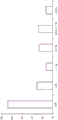
FIG. 5 depicts a histogram presenting the product distribution of the system of FIG. 1 in weight% (weight percent) according to one or more embodiments described in the present disclosure;
fig. 6 depicts a histogram presenting butene conversion (in weight%) in the system of fig. 1 according to one or more embodiments described in the present disclosure;
fig. 7 depicts a histogram presenting the product distribution (in weight%) of the system of fig. 2 in accordance with one or more embodiments described in the present disclosure;
fig. 8 depicts a histogram presenting the product distribution (in weight%) of the system of fig. 3 in accordance with one or more embodiments described in the present disclosure;
fig. 9 depicts a histogram presenting the product distribution (in weight%) of the system of fig. 4 in accordance with one or more embodiments described in the present disclosure;
for purposes of simplifying the schematic illustration and description of fig. 1-4, a number of valves, temperature sensors, electronic controllers, etc. that may be used and are well known to those of ordinary skill in certain refinery operations are not included. In addition, accompanying components in conventional refinery operations, including catalytic conversion processes, such as air suppliers, catalyst hoppers, and flue gas handling equipment, are not depicted. However, operational components, such as those described in the present disclosure, may be added to the embodiments described in the present disclosure.
Further, it should be noted that the arrows in the figures refer to transmission lines that may be used to transmit material flow between two or more system components. Further, the arrows connected to the system components define the inlet or outlet of each given system component. The direction of the arrow generally corresponds to the primary direction of movement of material in the material flow contained within the physical transport line indicated by the arrow. Further, an arrow not connecting two or more system components represents a product stream exiting the depicted system or a system inlet stream entering the depicted system. The product stream may be further processed in a companion chemical processing system or may be commercialized into a final product. The system inlet stream may be a stream delivered from an accompanying chemical treatment system, or may be an untreated feed stream.
Reference will now be made in detail to various embodiments, some of which are illustrated in the accompanying drawings. Wherever possible, the same reference numbers will be used throughout the drawings to refer to the same or like parts.
Detailed Description
In general, various embodiments of systems and methods for converting butenes to propylene are described in this disclosure. Generally, the conversion system includes system components operable to perform a process in which a feed stream comprising butenes undergoes a metathesis reaction and a cracking reaction to form propylene. In some embodiments, the metathesis reaction may be followed by a cracking reaction, where the metathesis and cracking reactions may be conducted in separate reactors arranged in series, or may be conducted in a single reactor containing multiple catalysts disposed in different portions of the reactor. After the metathesis and cracking reactions, the product stream may be split into multiple streams, some of which may optionally be recycled back into the system. After the downstream separation process, a product stream comprising at least about 80 wt.% propylene may be produced from the reaction products of the cracking reaction. The system can be operated with a single system inlet stream (e.g., a raffinate stream produced from a naphtha cracking process) comprising at least about 50 wt.% butenes. The system generally does not require a system inlet containing ethylene, and the process is fully functional without supplying ethylene to the system.
As used in this disclosure, a "transmission line" may include a pipe, conduit, channel, or other suitable physical transmission line that connects one or more system components to one or more other system components by fluid communication. As used in this disclosure, "system assembly" refers to any apparatus included in a system, such as, but not limited to, a separation unit, a reactor, a heat transfer device (e.g., a heater and a heat exchanger), a filter, an impurity removal device, a combination of various apparatuses, and so forth. A transmission line may generally transport a process stream between two or more system components. Typically, a transmission line may comprise multiple segments, where a "segment" of a transmission line comprises one or more portions of a transmission line, such that the transmission line may comprise multiple transmission line segments. Typically, the chemical composition of the process stream in a particular transfer line is similar or identical throughout the length of the transfer line. However, it should be appreciated that the temperature, pressure, or other physical properties of the process stream may vary within the transmission line, particularly in different transmission line sections. Also, relatively small compositional changes to the process stream, such as removal of impurities, may be made within the length of the transfer line. Also, the systems described in this disclosure are sometimes referred to as "butene conversion systems," which refers to any system that at least partially converts butene to one or more other chemicals. For example, in some embodiments, the butenes are at least partially converted to propylene. As described herein, a butene conversion system is suitable for processing a stream comprising butenes, including streams substantially free of other olefins (e.g., ethylene, propylene), into a product process stream comprising a substantial amount of propylene. As used in this disclosure, a material stream or composition is "substantially free of" or "substantially free of" a component when the component is present in an amount less than 0.1 weight percent.
As used in this disclosure, "separation unit" refers to any separation device that at least partially separates one or more chemicals that are mixed with each other in a process stream. For example, the separation unit may selectively separate chemical species that are different from each other, forming one or more chemical moieties. Examples of separation units include, but are not limited to, distillation columns, flash drums, knock-out pots, centrifuge filter devices, traps, purifiers, expansion devices, membranes, solvent extraction devices, and the like. It is understood that the separation processes described in this disclosure may not completely separate all of one chemical component from all of another chemical component. It is to be understood that the separation processes described in this disclosure separate different chemical components "at least partially" from one another, and even if not explicitly stated, it is to be understood that separation may include only partial separation. As used in this disclosure, one or more chemical components may be "separated" from a process stream to form a new process stream. Typically, a process stream may enter a separation unit and be divided or separated into two or more process streams having a desired composition. Further, in some separation processes, a "light fraction" and a "heavy fraction" may exit the separation unit, wherein, in general, the light fraction stream has a lower boiling point than the heavy fraction stream.
As used in this disclosure, "reactor" refers to a vessel in which one or more chemical reactions between one or more reactants can occur (optionally in the presence of one or more catalysts). For example, the reactor may comprise a tank or tubular reactor configured to operate as a batch reactor, a Continuous Stirred Tank Reactor (CSTR), or a plug flow reactor. Example reactors include packed bed reactors, such as fixed bed reactors, and fluidized bed reactors. The reactor may contain one or more catalyst sections, such as catalyst beds, where a "section" is a region of the reactor that contains a particular catalyst or groups of multiple catalysts. In another embodiment, the separation and reaction may be performed in a reactive separation unit.
As used in this disclosure, "catalyst" refers to any substance that can increase the rate of a particular chemical reaction. The catalysts described in this disclosure can be used to promote a variety of reactions, such as (but not limited to) metathesis or cracking reactions, or both. As used in this disclosure, a "metathesis catalyst" increases the reaction rate of the metathesis reaction, and a "cracking catalyst" increases the reaction rate of the cracking reaction. As used in this disclosure, "metathesis" generally refers to a chemical reaction in which fragments of an alkene (alkene) are redistributed by the breaking and regeneration of the alkene bond. Also, as used in this disclosure, "cleavage" generally refers to a chemical reaction in which a molecule having a carbon-carbon bond is broken into more than one molecule by the breaking of one or more carbon-carbon bonds. The total number of carbon atoms of the resulting cleaved molecule can be the same as the original molecule prior to cleavage.
Examples of Metathesis and cracking catalysts are disclosed in Saudi Aramco, U.S. provisional patent application No. 62/188,178 entitled "Dual Catalyst System for Propylene Production" (attorney docket No. SA 6019MA), and U.S. provisional patent application No. 62/188129 entitled "Propylene Production Using Mesoporous Silica Foam Metathesis catalysts" (attorney docket No. SA 6016 MA), the entire contents of each of which are incorporated by reference into this disclosure. As mentioned in these publications, suitable metathesis catalysts may include mesoporous silica catalysts impregnated with metal oxides. Suitable cracking catalysts may include mordenite framework reversed (MFI) structured silica catalysts. The mesoporous silica catalyst may include a pore size distribution of about 2.5nm to about 40nm and at least about 0.600cm3Total pore volume in g (cubic centimeters per gram). However, it is to be understood that the systems described in this disclosure may include any suitable metathesis and cracking catalysts, such as commercially available catalysts or catalysts targeted for future exploration.
Suitable reaction conditions for the metathesis and cracking reactions described in this disclosure may be varied by the catalyst composition used. However, in some embodiments, the metathesis or cracking reaction, or both, may be conducted at a temperature of about 500 ℃ (degrees celsius) to about 600 ℃ in atmospheric pressure.
As described in this disclosure, "butene" may include at least 1-butene, isobutylene, cis-2-butene, trans-2-butene, 2-methyl-2-butene, 3-methyl-1-butene, 2-methyl-1-butene, and cyclobutene. Butene (Butene) is sometimes referred to as Butene (Butene), and in the present disclosure, the terms "Butene (Butene)" and "Butene (Butene)" are used interchangeably. As described in this disclosure, "pentene" may include at least 1-pentene, cis-2-pentene, trans-2-pentene, 4-methyl-trans-2-pentene, cyclopentene and 2-methyl-2-pentene. As described in this disclosure, "hexene" can include at least trans-2-hexene, trans-3-hexene, cis-3-hexene, and cyclohexene. In the present invention, certain chemical substances may be represented by shorthand symbols, wherein C2 represents ethane, C3 represents propane, C4 represents ethane, C5 represents pentane, C6 represents hexane, C3 ═ represents propylene (propylene) (or propylene), C4 ═ represents butene (butene) (or butene (butylene)), C5 ═ represents pentene and C6 ═ represents hexene.
It is understood that when two or more process streams are "mixed" or "combined," when two or more lines intersect in the schematic flow diagrams of fig. 1-4. Mixing or combining may also include mixing by introducing the two streams directly into a similar reactor, separation device, or other system component.
A process for converting butenes to propylene, and a system for performing such a process, will now be described. In one embodiment, the butene conversion system may comprise a dual catalyst reactor, wherein the metathesis and cracking reactions are conducted in a single reactor, as described below with reference to fig. 1. Generally, according to the embodiment of fig. 1, a feed stream comprising butenes enters the system and undergoes a metathesis reaction followed by a cracking reaction in a single reactor. In one embodiment, the reactor contains a metathesis catalyst portion upstream of a cracking catalyst portion. The product stream of the cracking reaction comprises propylene and a product stream comprising propylene may be separated from the product stream of the cracking reaction. The embodiment of fig. 2 is similar to the embodiment of fig. 1, but includes a recycle stream. Typically, the recycle stream of fig. 2 may comprise butane and butene and is mixed with an inlet stream comprising butene. Thus, the feed stream entering the reactor of fig. 2 typically contains a greater percentage of butanes than the feed stream in the example of fig. 1.
In other embodiments, the butene conversion system may comprise a plurality of reactors in series, with the metathesis and cracking reactions being conducted in separate reactors, as described below with reference to fig. 3 and 4. The embodiment of fig. 3 is similar to the embodiment of fig. 1, but includes a series of reactors in which the metathesis and cracking reactions are carried out. In general, the stream compositions of fig. 1 and 3 may be similar or identical relative to similar inlet streams and reaction rates. The embodiment of fig. 4 is similar to the embodiment of fig. 3, but includes a recycle stream. Typically, the recycle stream of fig. 4 may comprise butanes and butenes and may be mixed with the metathesis-reaction products between the metathesis and cracking reactors.
It should be understood that while the embodiments of fig. 1-4 may have different mechanical devices or process stream compositions, or both, these embodiments typically share many of the same system components and transmission lines. Thus, the processes performed in similar system components in the various embodiments of FIGS. 1-4 may be similar or identical to each other. For example, the system components of fig. 1-4 labeled with the same reference numbers may perform similar or identical operations in various embodiments. Some of the process streams in the embodiments of fig. 1-4 may comprise similar or identical compositions, while others may not. For clarity, the transmission lines in the embodiments of fig. 1-4 each have a different reference number so that the composition of the material stream they contain can be easily identified. However, although in the various embodiments of fig. 1-4, some of the transfer lines may be located in similar areas and have similar functions, they may have substantially different compositions (such as in the case where a recycle stream is present or where the recycle stream re-enters at a different system location). Some of the process streams contained in similar regions of fig. 1-4 may be similar or even identical under similar process conditions (e.g., similar inlet stream compositions). For example, transmission lines/segments such as (but not limited to): the compositions of 201A, 310, 401A, and 501A may be similar or substantially the same; 204. 304, 404, and 504 may be similar or substantially identical in composition; 205. 305, 405, and 505 may be similar or substantially identical in composition; 207. 307, 407, and 507 may be similar or substantially the same in composition; 203 and 403 may be similar or substantially identical in composition; 206 and 406 may be similar or substantially identical in composition; 208, and 408 may be similar or substantially identical in composition. As provided in this disclosure, examples will help further illustrate the differences in process stream composition between the various embodiments.
Referring now to the process flow diagram of fig. 1, in one embodiment, the butene conversion system 100 may include a metathesis/cracking reactor 120 comprising a metathesis catalyst portion 122 and a cracking catalyst portion 124. Typically, a system inlet stream comprising butene enters the butene conversion system 100 via transfer line 201 (including sections 201A, 201B, 201C, and 201D) and is injected into the metathesis/cracking reactor 120. The system inlet stream to section 201A typically comprises at least butenes, and may optionally comprise other chemicals, such as butanes. For example, the system inlet stream may comprise at least about 20 wt%, 30 wt%, 40 wt%, 50 wt%, 55 wt%, 60 wt%, 65 wt%, or even at least about 70 wt% butenes. The system inlet stream may comprise at least about 15 wt.%, 20 wt.%, 25 wt.%, 30 wt.%, or even at least about 35 wt.% butane. The system inlet stream may comprise from 0 wt% to about 10 wt%, 8 wt%, 4 wt%, 2 wt%, or 1 wt% ethylene, or may be substantially free of ethylene.
The system inlet stream may be treated by one or more system components prior to entering the metathesis/cracking reactor 120. In such embodiments, the transmission line 201 may include several sections (depicted as 201A, 201B, 201C, and 201D) that may be separated by system components, such as the impurity removal device 110, the thermal transfer device 112, and the thermal transfer device 114. The impurity removal device 110 may remove oxygenates from the system inlet stream. In one embodiment, the impurity removal device 110 comprises a catalytic bed. The heat transfer device 112 may be a heat exchanger for increasing the temperature of the system inlet stream by exchanging energy with the stream in the transfer line 203A. The heat transfer device 114 may be a heater for further heating the system inlet stream. It is to be understood that the impurity removal device 110, the thermal transfer device 112, and the thermal transfer device 114 are optional components in the butene conversion system 100. It should be understood that all of the material flows located in the various sections of the transmission line 201 (i.e., 201A, 201B, 201C, and 201D) are considered part of the system inlet material flow, even though the chemical composition, temperature, or other characteristics of the system inlet material flow may be different in the various sections 201A, 201B, 201C, 201D.
Still referring to fig. 1, the metathesis/cracking reactor 120 includes a metathesis catalyst portion 122 and a cracking catalyst portion 124. The metathesis catalyst portion 122 is generally disposed upstream of the cracking catalyst portion 124, that is, the cracking catalyst portion 124 is generally disposed downstream of the metathesis catalyst portion 122. The system inlet stream from section 201D enters the metathesis/cracking reactor 120 and contacts the metathesis catalyst to undergo a metathesis reaction in the metathesis catalyst portion 122 to form a metathesis reaction product. After the metathesis reaction, the metathesis-reaction product is contacted with a cracking catalyst to undergo cracking, a cracking reaction in cracking catalyst portion 124. The cleavage reaction forms a cleavage reaction product. Typically, the reactants undergoing cracking or metathesis, or both, are homogeneously admixed with the respective catalyst during the reaction.
As used in this disclosure, "metathesis-reaction product" refers to the entire product mixture resulting from a metathesis reaction, including any portion of the product mixture that has not undergone metathesis. Further, as used in this disclosure, "cleavage reaction product" refers to the entire product mixture resulting from the cleavage reaction, including any portion of the product mixture that has not undergone cleavage. For example, the cleavage reaction product comprises all components of the process stream exiting the reactor in which the cleavage occurs.
The cracking-reaction product exits the metathesis/cracking reactor 120 as a cracking-reaction product stream via transfer line 203. The cleavage reaction product may comprise, consist of, or consist essentially of a mixture of alkanes and alkenes, including, but not limited to, ethylene, propylene, butene, pentene, hexene, heptene, ethane, propane, butane, pentane, hexane, and heptane. The cleavage reaction product may comprise at least about 2 wt.%, 4 wt.%, 6 wt.%, 8 wt.%, 10 wt.%, 12 wt.%, 14 wt.%, 16 wt.%, 18 wt.%, 20 wt.%, 22 wt.%, 24 wt.%, 26 wt.%, 28 wt.%, or even at least about 30 wt.% propylene.
The cleavage reaction product stream of the transfer line 203A formed in the metathesis/cleavage reactor 120 can be divided into one or more streams having a desired composition. Typically, a product stream comprising propylene (as shown in transfer line 207 in fig. 1) may be formed by separating the cracking reaction product stream. The product stream may comprise at least about 50 wt%, 60 wt%, 70 wt%, 80 wt%, 90 wt%, 95 wt%, 96 wt%, 97 wt%, 98 wt%, or even at least about 99 wt% propylene. It is understood that a wide variety of separation processes may be utilized to produce a product stream comprising propylene.
In one embodiment, as shown in fig. 1, the cleavage reaction product may be transported via a transfer line 203 to one or more separation units, which may comprise a section 203A and a section 203B, wherein the sections are separated by a heat transfer device 112. The cracked reaction product may enter a separation unit 130 where light components, such as ethylene and ethane, may be removed. Light components (e.g., ethylene) can be purged from the butene conversion system 100 via transfer line 204 or can be used in other chemical systems via transfer line 205. The streams contained in transfer line 204 and transfer line 205 can comprise, consist of, or consist essentially of ethylene. For example, the stream of transmission line 204 or transmission line 205, or both, may comprise at least about 50, 60, 70, 80, 90, 95, 96, 97, 98, or even at least about 99 weight percent ethylene. The heavy portion from the separation unit 130 may exit the separation unit 130 via a transfer line 206. The process stream of the transmission line 206 may comprise a mixture of alkanes and alkenes including, but not limited to, one or more of propylene, butene, pentene, hexene, heptene, ethane, propane, butane, pentane, hexane, and heptane. The process stream in line 206 can enter separation unit 140 where propylene is separated from other components. The light portion (i.e., propylene) can exit the separation unit 140 as a propylene product stream via transfer line 207. The propylene product stream contained in the transfer line 207 can comprise, consist of, or consist essentially of propylene. For example, the stream of transfer line 204 or transfer line 205, or both, may comprise at least about 50, 60, 70, 80, 90, 95, 96, 97, 98, or even at least about 99 weight percent propylene. The heavy portion from separation unit 140 may exit separation unit 140 via transfer line 208. The process stream in line 208 can comprise a mixture of alkanes and alkenes, including, but not limited to, one or more of butene, pentene, hexene, heptene, propane, butane, pentane, hexane, and heptane. The stream of transfer line 208 can be purged from the butene conversion system 100 as a final product or can be further separated in subsequent processing.
With reference to the above, the embodiment of fig. 2 is similar to the embodiment of fig. 1, but contains a recycle stream comprising butane and butene. Generally, in the embodiment of fig. 2, the recycle stream of transfer line 312 can comprise butane and butene and is mixed with the inlet stream of transfer line 310 comprising butene. The stream of transfer line section 301D enters the reactor and thus may typically contain a greater percentage of butane than the stream of transfer line section 201D of fig. 1. Typically, the addition of a recycle stream, as described with reference to fig. 2, can increase propylene selectivity and propylene yield.
Referring now to the process flow diagram of fig. 2, in one embodiment, the butene conversion system 200 may include a metathesis/cracking reactor 120 comprising a metathesis catalyst portion 122 and a cracking catalyst portion 124. Typically, a system inlet stream comprising butene enters the butene conversion system 200 via transfer line 310. The system inlet stream of the transfer line 310 typically comprises at least butenes, and may optionally comprise other chemicals, such as butanes. For example, the system inlet stream of the transfer line 310 can comprise at least about 20, 30, 40, 50, 55, 60, 65, or even at least about 70 weight percent butenes, and can comprise at least about 15, 20, 25, 30, or at least about 35 weight percent butanes. The system inlet stream of the transfer line 310 can comprise from 0 wt% to about 10 wt%, 8 wt%, 4 wt%, or 2 wt% ethylene, or can be substantially free of ethylene.
The system inlet stream in transfer line 310 is combined with the recycle stream in transfer line 312 to form the mixture stream in transfer line 301. The mixture stream passes through transfer line 301 and is introduced into metathesis/cracking reactor 120. In an embodiment, the recycle stream of transfer line 312 can comprise butenes and butanes. For example, the recycle stream of transfer line 312 can comprise at least about 5 wt%, 10 wt%, 15 wt%, or even at least about 20 wt% butenes, and can comprise at least about 50 wt%, 60 wt%, 70 wt%, or even more than about 80 wt% butanes. The recycle stream of transfer line 312 can comprise at least about 80 wt.%, 90 wt.%, or even at least about 95 wt.% butane in combination with butene.
The mixture stream of the transmission line 301 can include butanes and butenes. For example, the mixture stream of the transmission line 301 can comprise at least about 5 wt%, 10 wt%, 15 wt%, 20 wt%, 25 wt%, 30 wt%, or even at least about 35 wt% butenes, and can comprise at least about 40 wt%, 50 wt%, 60 wt%, 70 wt%, or even at least about 80 wt% butanes. The mixture stream of the transmission line 301 can comprise at least about 80 wt.%, 90 wt.%, or even at least about 95 wt.% butane in combination with butene.
The mixture stream may be processed by one or more system components prior to entering the metathesis/cracking reactor 120. In such embodiments, the transmission line 301 may include several segments (depicted as 301A, 301B, 301C, and 301D) that may be separated by system components, such as the impurity removal device 110, the thermal transfer device 112, and the thermal transfer device 114.
After the metathesis and cracking reactions in the reactor 120, the cracking reaction product of the transmission line section 303A may comprise, consist of, or consist essentially of a mixture of alkanes and alkenes, including, but not limited to, one or more of ethylene, propylene, butene, pentene, hexene, heptene, ethane, propane, butane, pentane, hexane, and heptane. For example, the cleavage reaction product in the embodiment of fig. 2 may comprise at least about 2 wt.%, 4 wt.%, 6 wt.%, 8 wt.%, 10 wt.%, 12 wt.%, 14 wt.%, 16 wt.%, 18 wt.%, or even at least about 20 wt.% propylene.
As described with reference to the example of fig. 1, the cracking-reaction product of the example of fig. 2, formed in the metathesis/cracking reactor 120, may be divided into one or more streams of desired composition. Typically, the product stream (of transfer line 307) comprising propylene may be formed by separating propylene from the cleavage reaction product stream of transfer line 303A. The product stream of transfer line 307 may comprise at least about 50 wt.%, 60 wt.%, 70 wt.%, 80 wt.%, 90 wt.%, 95 wt.%, 96 wt.%, 97 wt.%, 98 wt.%, or even at least about 99 wt.% propylene. It is understood that a wide variety of separation processes may be utilized to produce a product stream comprising propylene.
In one embodiment, as shown in fig. 2, the cleavage reaction product may be introduced to one or more separation units via a transfer line 303, which may comprise a section 303A and a section 303B, wherein the sections are separated by a heat transfer device 112. Similar to the previously described embodiment of fig. 1, the cleavage reaction product may enter a separation unit 130, where ethylene and other light components may be at least partially removed. After separation of the ethylene by separation device 130, the propylene may be separated from the heavy portion of separation unit 130 in separation unit 140. The heavy portion from separation unit 140 may exit separation unit 140 via transfer line 308. The stream in line 308 can comprise a mixture of alkanes and alkenes including, but not limited to, one or more of butene, pentene, hexene, heptene, propane, butane, pentane, hexane, and heptane.
The process stream of the transfer line 308 may be injected into the separation unit 150, where one or more portions may be separated from each other. In one embodiment, the heavy portion may exit the separation unit 150 in the form of a stream contained in the transfer line 314. The stream of material in transfer line 314 may comprise one or more of pentene, pentane, hexene, heptene, pentane, hexane, and heptane. The light portion of the separation unit 150, which comprises primarily butenes and butanes, may exit the separation unit 150 as a recycle stream contained in transfer line 312. A portion of the recycle stream contained in transfer line 312 can be purged from system 200 via transfer line 316. The remainder may be recycled to the system 200 by combining the material flow of the transfer line 312 with the system inlet material flow of the transfer line 310.
In another embodiment, as described with reference to fig. 3, the butene conversion system 300 may comprise a plurality of reactors in series, wherein the metathesis and cracking reactions are conducted in separate reactors. The embodiment of fig. 3 is similar to the embodiment of fig. 1, but includes separate metathesis and catalyst reactors in series. In some embodiments, it may be advantageous to utilize reactors in series, such as when the metathesis and cleavage reactions are conducted under different reaction conditions (e.g., different temperatures or/and pressures). The other system components (non-reactor) of fig. 3 may generally be similar or identical to the components described with reference to fig. 1. The embodiment of fig. 3 may produce similar or identical butene conversion, propylene selectivity, and propylene yield as compared to the embodiment of fig. 1. Further, the composition of the process streams in the embodiment of fig. 3 may be similar or identical to that of fig. 1.
Referring now to the process flow diagram of fig. 3, in one embodiment, the butene conversion system 300 may include a metathesis reactor 121 comprising a metathesis catalyst portion 122, and a cracking reactor 123 comprising a cracking catalyst portion 124. Typically, a system inlet stream comprising butene enters the butene conversion system 300 via transfer line 401 and is injected into the metathesis reactor 121. The system inlet stream typically comprises at least butenes, and may optionally comprise other chemicals, such as butanes. For example, the system inlet stream of the transmission line 401 may comprise at least about 20 wt.%, 30 wt.%, 40 wt.%, 50 wt.%, 55 wt.%, 60 wt.%, 65 wt.%, or even at least about 70 wt.% butenes. The system inlet stream may comprise at least about 15 wt.%, 20 wt.%, 25 wt.%, 30 wt.%, or even at least about 35 wt.% butane.
Still referring to fig. 3, the metathesis reactor 121 includes a metathesis catalyst portion 122, such as a metathesis catalyst bed, and the cracking reactor 123 includes a cracking catalyst portion 124, such as a cracking catalyst bed. The metathesis reactor 121 and the cleavage reactor 123 are arranged in series, with the metathesis reactor 121 generally disposed upstream of the cleavage reactor 123, that is, the cleavage reactor 123 generally disposed downstream of the metathesis reactor 121. The system inlet stream from section 401D enters the metathesis reactor 121 and undergoes a metathesis reaction in the metathesis catalyst portion 122 to form a metathesis-reaction product. The metathesis-reaction product may exit the metathesis reactor in the form of a metathesis-reaction product stream via transfer line 410. The metathesis-reaction product stream enters the cracking reactor 123 and is cracked in a cracking reaction in the cracking catalyst section 124. The cleavage reaction forms a cleavage reaction product. The cracking reaction product leaves the cracking reactor 123 via transfer line 403 in the form of a cracking reaction product stream. The cleavage reaction product may comprise, consist of, or consist essentially of a mixture of alkanes and alkenes, including, but not limited to, one or more of ethylene, propylene, butene, pentene, hexene, heptene, ethane, propane, butane, pentane, hexane, and heptane. The cleavage reaction product may comprise at least about 2 wt.%, 4 wt.%, 6 wt.%, 8 wt.%, 10 wt.%, 12 wt.%, 14 wt.%, 16 wt.%, 18 wt.%, 20 wt.%, 22 wt.%, 24 wt.%, 26 wt.%, 28 wt.%, or even at least about 30 wt.% propylene.
Similar to the embodiment of fig. 1, in the embodiment of fig. 3, the cleavage reaction product may be divided into one or more streams having the desired composition. Typically, a product stream comprising propylene (in transfer line 407) may be formed by separating propylene from the other components of the cracking reaction product stream. The product stream of transfer line 407 may comprise at least about 50 wt%, 60 wt%, 70 wt%, 80 wt%, 90 wt%, 95 wt%, 96 wt%, 97 wt%, 98 wt%, or even at least about 99 wt% propylene. It is understood that a wide variety of separation processes may be utilized to produce a product stream comprising propylene. As shown in fig. 3, a plurality of separation units may be utilized.
Referring now to fig. 4, the embodiment of fig. 4 is similar to that of fig. 3, but includes a recycle stream in transfer line 512. Typically, the recycle stream of fig. 3 (in transfer line 512) may comprise butanes and butenes, and may be mixed with the metathesis-reaction product stream in transfer line 510 between the metathesis reactor 121 and the cracking reactor 123.
Still referring to the process flow diagram of fig. 4, in one embodiment, the butene conversion system 400 may include a metathesis reactor 121 comprising a metathesis catalyst portion 122 and a cracking reactor 123 comprising a cracking catalyst portion 124. Typically, a system inlet stream comprising butene enters the butene conversion system 400 via transfer line 501 and is injected into the metathesis reactor 121. The system inlet stream typically comprises at least butenes, and may optionally comprise other chemicals, such as butanes. For example, the system inlet stream may comprise at least about 20 wt%, 30 wt%, 40 wt%, 50 wt%, 55 wt%, 60 wt%, 65 wt%, or even 70 wt% butenes. The system inlet stream may comprise at least about 15 wt.%, 20 wt.%, 25 wt.%, 30 wt.%, or even 35 wt.% butane.
The system inlet stream from section 501D enters the metathesis reactor 121 and undergoes a metathesis reaction in the metathesis catalyst portion 122 to form a metathesis-reaction product. The metathesis-reaction products may exit the metathesis reactor 121 in the form of a metathesis-reaction product stream via transfer line 510. The metathesis-reaction product stream contained in transfer line 510 is combined with the recycle stream of transfer line 512 to form a mixture stream in transfer line 520. In an embodiment, the recycle stream of the transfer line 512 can comprise butenes and butanes. For example, the recycle stream of transfer line 512 can comprise at least about 5 wt%, 10 wt%, 15 wt%, 20 wt%, 25 wt%, 30 wt%, or even at least about 35 wt% butenes, and can comprise at least about 40 wt%, 50 wt%, 60 wt%, 70 wt%, or even at least about 80 wt% butanes. The recycle stream of the transfer line 512 can comprise at least about 80 wt.%, 90 wt.%, or even at least about 95 wt.% butane in combination with butene.
The mixture stream of the transfer line 520 enters the cleavage reactor 123 and is cleaved in the cleavage reaction in the cleavage catalyst portion 124. The cleavage reaction forms a cleavage reaction product. The cracking reaction product exits the cracking reactor 123 as a cracking reaction product stream via transfer line 503. The cleavage reaction product may comprise, consist of, or consist essentially of a mixture of alkanes and alkenes, including, but not limited to, one or more of ethylene, propylene, butene, pentene, hexene, heptene, ethane, propane, butane, pentane, hexane, and heptane. The cleavage reaction product may comprise at least about 1 wt.%, 2 wt.%, 3 wt.%, 4 wt.%, 5 wt.%, 6 wt.%, 7 wt.%, 8 wt.%, 10 wt.%, 15 wt.%, or even at least about 20 wt.% propylene.
As described with reference to the embodiment of fig. 3, the cleavage reaction product formed in the cleavage reactor 123 (in the transfer line 503A) may be divided into one or more streams of desired composition. Typically, a product stream comprising propylene (in transfer line 507) may be formed by separating propylene from the other components of the cracking reaction product stream. The product stream of transfer line 507 may comprise at least about 50 wt%, 60 wt%, 70 wt%, 80 wt%, 90 wt%, 95 wt%, 96 wt%, 97 wt%, 98 wt%, or even at least about 99 wt% propylene. It is understood that a wide variety of separation processes may be utilized to produce a product stream comprising propylene.
In one embodiment, as shown in fig. 4, the cleavage reaction product may be introduced to one or more separation units via transfer line 503, which may comprise section 503A and section 503B, wherein each section is separated by heat transfer device 112. Similar to the embodiment of fig. 1 and 3, the cleavage reaction product may enter a separation unit 130, where ethylene and other light components may be removed. After separation of the ethylene by separation device 130, the propylene may be separated from the heavy portion of separation unit 130 in separation unit 140. The heavy portion from separation unit 140 may exit separation unit 140 via transfer line 508. The stream in line 508 can comprise a mixture of alkanes and alkenes including, but not limited to, one or more of butene, pentene, hexene, heptene, propane, butane, pentane, hexane, and heptane.
The process stream of the transfer line 508 may be injected into the separation unit 150, where one or more portions may be separated from each other. In one embodiment, the bottom portion may exit the separation unit 150 as a stream contained in the transfer line 514. The process stream of transfer line 514 may comprise one or more of pentene, pentane, hexene, hexane, heptene, and heptane. The light fraction may exit the separation unit 150 in the form of a stream contained in transfer line 516 and be purged from the system 400. The stream of transfer line 516 can comprise one or more of butenes and butanes, for example, at least about 20 wt.%, 30 wt.%, 40 wt.%, or even at least about 50 wt.% butanes. The recycle stream contained in transfer line 512 can be recycled to the system 400 by combining the stream of transfer line 512 with the metathesis product stream of transfer line 510. In one embodiment, the recycle stream of 512 can be a portion of the overhead stream of transfer line 516.
Generally, streams containing butanes and butenes suitable for use as inlet streams in the embodiments described in this disclosure may result from refining operations. This stream containing butanes and butenes may be split into portions to form a first raffinate, a second raffinate, and a third raffinate. In one embodiment, the system inlet stream may be a raffinate stream from an alkene refining system (e.g., a conventional refinery). Streams resulting from refinery operations may typically include C4 alkanes and alkenes, including butanes, butenes, and butadienes. The "first raffinate" may be produced by separating 1, 3-butadiene from the other C4 components in the feed stream. The first raffinate may comprise isobutylene, cis-2-butene, and trans-2-butene. For example, the first raffinate may comprise, or consist essentially of, about 40 wt% to about 50 wt%, about 35 wt% to about 55 wt%, or about 30 wt% to about 60 wt% isobutylene and about 30 wt% to about 35 wt%, about 25 wt% to about 40 wt%, or about 20 wt% to about 45 wt% cis-2-butene and trans-2-butene collectively. The "second raffinate" can be produced by separating isobutene from the other C4 components of the first raffinate. For example, the second raffinate can comprise from about 50 wt% to about 60 wt%, from about 45 wt% to about 65 wt%, or from about 40 wt% to about 70 wt% cis-2-butene and trans-2-butene, in total; about 10 wt% to about 15 wt%, about 5 wt% to about 20 wt%, or about 0 wt% to about 25 wt% 1-butene; and from about 15 wt% to about 25 wt%, from about 10 wt% to about 30 wt%, or from about 5 wt% to about 35 wt% butane. The inlet stream of the systems described herein can be substantially free of isobutylene and can consist essentially of 2-butene and n-butane.
Referring to the examples of catalytic reactions described herein, as shown in formulas 1 and 2 below, "metathesis" or "autometathesis" can generally be a two-step process: 2-butene is isomerized and then cross-metathesized using a metathesis catalyst system. As shown in the following formula 3, in embodiments, "catalytic cracking" may refer to C4-C6Conversion of olefins to propylene and other alkanes and/or alkenes, e.g. C1-C2An olefin.
Formula 1: 2-butene isomerization

Formula 2: cross metathesis

Formula 3: catalytic cracking

With reference to formulas 1-3, "metathesis" and "catalytic cracking" reactions are not limited to these reactants and products; however, formulas 1-3 provide a basic description of the reaction process according to some embodiments. As shown in formulas 1 and 2, the metathesis reaction is carried out between two olefins. The groups bonded to the carbon atoms in the double bond are exchanged between the molecules to produce two new olefins with exchanged groups. The particular catalyst selected for the olefin metathesis reaction may generally determine the formation of the cis isomer or the trans isomer, since coordination of the olefin molecule to the catalyst plays an important role, such as steric effects of substituents on the double bond of the newly formed molecule.
In one embodiment, the dual catalyst system of the present invention comprises: a mesoporous silica catalyst that is a mesoporous silica catalyst support impregnated with a metal oxide; and a mordenite framework reversed (MFI) structured silica catalyst located downstream of the mesoporous silica catalyst. A variety of structures are contemplated for the mesoporous silica catalyst support, such as molecular sieves. As used in this application, "mesoporous" means that the silica support has a narrow pore size distribution. Specifically, the mesoporous silica catalyst includes a narrow pore size distribution of about 2.5nm (nanometers) to about 40nm and at least about 0.600cm3Total pore volume in g. Without wishing to be bound by theory, the pore size distribution and pore volume of the present invention are sized to obtain better catalytic activity and reduce clogging of the pores by metal oxides, while smaller pore volumes and pore size catalyst systems are sensitive to pore clogging and thereby reduce catalytic activity.
Furthermore, the use of an MFI structured silica catalyst downstream of the mesoporous silica catalyst unexpectedly provides for the optimal production of propylene from the butene stream. One of ordinary skill in the art would expect the best yield to be obtained by first cracking the butenes to propylene, and then cracking any remaining butenes via metathesis. However, it was unexpectedly found that propylene yield was increased and, in addition, the combined yield of propylene and ethylene was increased by placing an MFI structured silica catalyst downstream of the mesoporous silica catalyst.
In one or more embodiments, the mesoporous silica catalyst may have a pore size distribution in the range of from about 2.5nm to about 40nm, or from about 2.5nm to about 20nm, or from about 2.5nm to about 4.5nm, or from about 2.5nm to about 3.5nm, or from about 8nm to about 18nm, or from about 12nm to about 18 nm. In other embodiments, the total pore volume may be about 0.600cm3G to about 2.5cm3In g, or about 0.600cm3G to about 1.5cm3In g, or about 0.600cm3G to about 1.3cm3In g, or about 0.600cm3G to about 0.800cm3In g, or about 0.600cm3G to about 0.700cm3In g, or about 0.900cm3G to about 1.3cm3/g。
Further, although broader ranges are contemplated, in one or more embodiments, the mesoporous silica catalyst may comprise about 250 square meters per gram (m)2Per g) to about 600m2Surface area in g. In other embodiments, the mesoporous silica catalyst may have a particle size of about 450m2G to about 600m2In g, or about 250m2G to about 350m2Per g, or about 275m2G to about 325m2Per g, or about 275m2G to about 300m2Surface area in g. Further, the mesoporous silica catalyst can have a total acidity of up to about 0.5 millimoles per gram (mmol/g), or from about 0.01mmol/g to about 0.5mmol/g, or from about 0.1mmol/g to about 0.5mmol/g, or from about 0.3mmol/g to about 0.5mmol/g, or from about 0.4mmol/g to about 0.5 mmol/g. Acidity is typically maintained at or below about 0.5mmol/g to produce the desired propylene selectivity and to reduce the production of undesirable by-products such as aromatics. The overall butene conversion rate can be increased by improving the acidity; however, such increased conversion can result in lower selectivity and increased production of aromatic byproducts, which can cause coking and deactivation of the catalyst.
In addition, the mesoporous silica catalyst may have a particle size of from about 20nm to about 200nm, or from about 50nm to about 150nm, or from about 75nm to about 125 nm. In other embodiments, the mesoporous silica catalyst may have an individual crystal size of from about 1 μm to about 100 μm, or from about 10 μm to about 40 μm.
Various formulations for mesoporous silica supports and methods of making the formulations are contemplated. For example, mesoporous silica catalyst supports may be produced by wet impregnation, hydrothermal synthesis, or both methods. Further, the mesoporous silica catalyst support may be characterized by an ordered pore structure. For example, such an ordered structure may have a hexagonal hole array. One suitable example of a mesoporous silica support having a hexagonal pore array may be the Santa Barbara Amorphous (SBA-15) mesoporous silica molecular sieve. Alternatively, another suitable example of a mesoporous silica support is a CariACT Q-10(Q-10) spherical catalyst support produced by Fuji Silysia Chemical Ltd.
The catalyst for the metathesis reaction is an impregnated metal oxide of a silica support. The metal oxide may comprise one or an oxide of a metal from groups 6 to 10 of the IUPAC periodic table. In one or more embodiments, the metal oxide can be an oxide of molybdenum, rhenium, tungsten, or a combination thereof. In a particular embodiment, the metal oxide is tungsten oxide (WO)3). It is contemplated that various amounts of metal oxide can be impregnated into the mesoporous silica catalyst support. By way of example and not limitation, silicon dioxide and metal oxides (e.g., WO)3) Is from about 5 to about 60, or from about 5 to about 15, or from about 20 to about 50, or from about 20 to about 40, or from about 25 to about 35.
In one or more embodiments, the metathesis catalyst can comprise an amorphous mesoporous silica foam impregnated with a metal oxide. As used in this application, "amorphous mesoporous silica foam" means a silica support having a disordered structure and a narrow pore size distribution. This disordered structure can be random and therefore different from the disclosed hexagonal or cubic structure of conventional silica supports. In particular, the amorphous mesoporous silica foam has a narrow pore size distribution of at least 3nm to about 40nm and at least0.700cm3Total pore volume in g. Without wishing to be bound by theory, the pore size distribution and pore volume of the present invention are sized to obtain better catalytic activity and reduce clogging of the pores by the metal oxide, while smaller pore volumes and pore size metathesis catalysts are sensitive to pore clogging and thereby reduce catalytic activity. Reduced plugging can lead to higher metal oxide species on amorphous mesoporous silica foams (e.g., WO)3) Degree of dispersion. Higher WO3The degree of dispersion can lead to higher metathesis activity and therefore higher propylene yields.
In one or more embodiments, the pore size distribution of the metal oxide impregnated amorphous mesoporous silica foam may range from at least 3nm to about 40nm, or from about 3nm to about 20nm, or from about 4nm to about 10nm, or from about 4nm to about 8nm, or from about 4nm to about 6 nm. In other embodiments, the total pore volume may be at least 0.700cm3G to about 2.5cm3In g, or about 0.800cm3G to about 2.5cm3In g, or about 0.800cm3G to about 1.5cm3In g, or about 0.800cm3G to about 1.25cm3In g, or about 0.800cm3G to about 1.0cm3In g, or about 0.850cm3G to about 1.0cm3/g。
In addition, the metal oxide impregnated amorphous mesoporous silica foam may have a total acidity of about 0.125 millimoles per gram (mmol/g) to about 0.500 mmol/g. Without wishing to be bound by theory, if the material exceeds 0.500mmol/g, other adverse side reactions, such as cracking and hydrogen transfer reactions, may be caused. In other embodiments, the metal oxide impregnated amorphous mesoporous silica foam may have a total acidity of from about 0.125mmol/g to about 0.250mmol/g, or from about 0.125mmol/g to about 0.150 mmol/g. Although various surface areas are contemplated, in one or more embodiments, the metathesis catalyst can have at least about 400 meters2Per gram (m)2/g), or about 400m2G to about 800m2In g, or about 400m2G to about 500m2In g, or about 400m2G to about 450m2Per g, or about 425m2G to about 450m2Surface area in g.
The catalyst for the metathesis reaction may be an impregnated metal oxide of the silica foam. The metal oxide may comprise one of the metals from IUPAC groups 6 to 10 of the periodic table or an oxide thereof. In one or more embodiments, the metal oxide can be an oxide of molybdenum, rhenium, tungsten, or a combination thereof. In a particular embodiment, the metal oxide is tungsten oxide (WO)3). It is contemplated that various amounts of metal oxide can be impregnated into the amorphous mesoporous silica foam. By way of example and not limitation, silicon dioxide and metal oxides (e.g., WO)3) Is from about 1 to about 50, or from about 1 to about 40, or from about 5 to about 30, or from about 5 to about 15. In addition, the metathesis catalyst can include from about 1 to about 50 wt.%, or from about 2 to about 25 wt.%, or from about 5 to about 15 wt.% metal oxide, e.g., WO3。
In addition, other optional components may be included in the impregnated mesoporous silica foam catalyst. For example, the metathesis catalyst can include a structuring agent. In one embodiment, the structuring agent is a triblock copolymer structuring agent. In another embodiment, the triblock copolymer structurant is a poly (ethylene glycol) -block-poly (propylene glycol) -block-poly (ethylene glycol) structure, which may also be referred to as a poloxamer (poloxamer) structure. One suitable commercially available example of a surfactant triblock copolymer structurant is from BASF Corporation
In addition, various silica structures are contemplated for use in MFI structured silica catalysts. For example, the MFI structured silica catalyst may comprise an MFI structured aluminosilicate zeolite catalyst or an MFI structured silica catalyst that is free of alumina. As used herein, "free" means less than 0.001 wt% alumina is present in the MFI structured silica catalyst. Further, it is contemplated that the MFI structured silica catalyst may include other impregnated metal oxides in addition to or as an alternative to alumina. Similar to mesoporous silica catalysts, MFI structured catalysts may have alumina, metal oxide, or both impregnated in a silica support. In addition to or as an alternative to alumina, it is contemplated to include the previously listed metal oxides, specifically, one or more oxides of metals from groups 6-10 of the IUPAC periodic table, more specifically metal oxides of molybdenum, rhenium, tungsten, titanium, or combinations thereof.
For MFI structured aluminosilicate zeolite catalysts, various amounts of alumina are contemplated. In one or more embodiments, the molar ratio of silica to alumina in the MFI structured aluminosilicate zeolite catalyst may be from about 5 to about 5000, or from about 100 to about 4000, or from about 200 to about 3000, or from about 1500 to about 2500, or from about 1000 to about 2000. Various suitable commercially available examples of MFI structured aluminosilicate zeolite catalysts are contemplated, for example ZSM-5 zeolites such as MFI-280 produced by ZeolystInternational or MFI-2000 produced by Saudi Aramco.
Various suitable commercial examples of MFI structured catalysts that are alumina-free are also contemplated. One such example is Silicalite-1, manufactured by Saudi Aramco.
The MFI structured silica catalyst may comprise a pore size distribution of about 1.5nm to 3nm, or about 1.5nm to 2.5 nm. Further, the MFI structured silica catalyst may have about 300m2G to about 425m2In terms of/g, or about 340m2G to about 410m2Surface area in g. Further, the MFI structured silica catalyst can have a total acidity of from about 0.001mmol/g to about 0.1mmol/g, or from about 0.01mmol/g to about 0.08 mmol/g. Acidity is maintained at or below about 0.1mmol/g to reduce the production of undesirable by-products such as aromatics. Increasing acidity increases the amount of cracking; however, this increased cracking can also lead to lower selectivity and increased production of aromatic byproducts, which can cause coking and deactivation of the catalyst.
In some cases, the MFI structured silica catalyst may be modified with an acidity regulator to adjust the degree of acidity in the MFI structured silica catalyst. For example, these acidity regulators may include rare earth regulators, phosphorus regulators, potassium regulators, or combinations thereof. However, since the embodiments of the present invention focus on reducing acidity to a level of 0.1mmol/g or less, the structured silica catalysts of the present invention can be free of acidity regulators, such as a regulator selected from rare earth regulators, phosphorus regulators, potassium regulators, or combinations thereof. As used herein, "free of an acidity regulator" means that less than 0.001 wt% of the acidity regulator is present in the MFI structured silica catalyst.
Further, the MFI structured silica catalyst may have about 0.1cm3G to about 0.3cm3In g, or about 0.15cm3G to about 0.25cm3Pore volume in g. Further, the MFI structured silica catalyst may have an individual crystal size in the range of from about 10nm to about 40 μm, or from about 15 μm to about 40 μm, or from about 20 μm to about 30 μm. In another embodiment, the MFI structured silica catalyst may have an individual crystal size in the range of about 1 μm to about 5 μm.
In addition, various amounts of each catalyst are contemplated for use in the dual catalyst system of the present invention. For example, it is contemplated that the metathesis catalyst to cracking catalyst volume ratio can be in the range of from about 5:1 to about 1:5, or from about 2:1 to about 1:2, or about 1: 1.
In operation, a product stream comprising propylene is produced from a butene-containing stream via metathesis conversion by contacting the butene stream with a dual catalyst system. The butene stream may comprise 2-butene, and optionally one or more isomers, such as 1-butene, trans-2-butene, and cis-2-butene. The discussion of the present invention focuses on butene-based feed streams; however, it is well known that other C's may also be present in the feed stream1-C6And (4) components.
The mesoporous silica catalyst may be a metathesis catalyst that facilitates the isomerization of 2-butene to 1-butene followed by cross-metathesis of the 2-butene and 1-butene into a metathesis product stream comprising propylene and other olefins/alkanes (e.g., pentene). The MFI structured silica catalyst (which is located downstream of the metathesis catalyst) is a cracking catalyst that is derived from C in the metathesis product stream4Or C5Olefins produce propylene and may also produce ethylene.
Although specific catalyst compositions have been described, it should be understood that embodiments of the methods and systems of the present application may incorporate any catalyst useful for metathesis or cracking of the reactant compositions described.
Examples of the invention
Various embodiments of methods and systems for cracking a light fuel fraction and a heavy fuel fraction by fluidized catalytic cracking will be further illustrated by the following examples. The examples are illustrative in nature and should not be construed as limiting the subject matter of the present disclosure.
Example 1
The system of FIG. 1 is used (available from AspentTech) computer modeling. Subsequent tables (tables 1-4) depict the stream compositions and thermal properties of the selected streams. The reaction rates provided for the simulations represent the experimental reaction rates of the metathesis Catalyst W-SBA-15 and the cleavage Catalyst MFI-2000 as described in examples 1,3 and 6 of Saudi Aramco U.S. provisional patent application No. 62/188,178 (attorney docket No. SA 6019MA) entitled "Dual Catalyst System for Propylene Production" in the application. A system inlet stream having 35 wt% cis-2-butene, 35 wt% trans-2-butene, and 30 wt% n-butane was used in the model. The stream numbers in the table correspond to the streams or stream sections shown in fig. 1. Simulations were performed for 100% efficacy and 80% efficacy. For each simulation, simulation data is provided on a weight basis and on a molar basis. Specifically, table 1 depicts simulated data for the system of fig. 1 at 100% efficacy and shows the components on a mass basis. Table 2 depicts simulated data for the system of fig. 1 at 100% efficacy and shows the components based on moles. Table 3 depicts simulated data for the system of fig. 1 at 80% efficacy and shows the components on a mass basis. Table 4 depicts simulated data for the system of fig. 1 at 80% efficacy and shows the components based on moles. In addition, FIG. 6 depicts a histogram, which presents the product distribution of the system of FIG. 1 as shown in Table 1,wherein on the histogram, "propylene" corresponds to the material flow for
 transmission line 207, "ethylene" corresponds to the material flow for transmission line 205, "light purge" corresponds to the material flow for transmission line 204, and "C4/C5 + heavy compounds" corresponds to the material flow for transmission line 208. Fig. 7 depicts a bar chart showing butene conversion products after metathesis and cracking reactions. The product distribution of fig. 6 and the butene conversion product of fig. 7 are based on the Aspen (Aspen) simulation of table 1.
Table 1-figure 1 at 100% efficacy, wt. -%


Table 2-figure 1, mol% at 100% efficacy


Table 3-figure 1 at 80% efficacy, wt. -%

Table 4-figure 1 at 80% efficacy, mol%


Example 2
The system of FIG. 2 also uses And (5) modeling by using a computer. Subsequent tables (tables 5-8) depict the stream compositions and thermal properties of the selected streams. The system inlet stream composition and catalyst reaction rate used in the model were the same as for example 2. The stream number corresponds to the stream or stream section shown in fig. 2. Simulations were performed for 100% efficacy and 80% efficacy. In addition, data is provided on a weight basis and on a mole basis for each simulation. Table 5 depicts simulated data for the system of fig. 2 at 100% efficacy and shows the components on a mass basis. Table 6 depicts simulated data for the system of fig. 2 at 100% efficacy and shows the components based on moles. Table 7 depicts simulated data for the system of fig. 2 at 80% efficacy and shows the components on a mass basis. Table 8 depicts simulated data for the system of fig. 2 at 80% efficacy and shows the components based on moles. Further, fig. 8 depicts a histogram presenting the product distribution of the system of fig. 2 as shown in table 5, where on the histogram, "propylene" corresponds to the material flow of
 transmission line 307, "ethylene" corresponds to the material flow of transmission line 305, "light purge" corresponds to the material flow of transmission line 304, "C4 purge" corresponds to the material flow of transmission line 316, and "C5 + heavy compounds" corresponds to the material flow of transmission line 314. The product distribution of fig. 8 is based on Aspen simulation of table 5.
Table 5-figure 2 at 100% efficacy, wt. -%

Table 6-figure 2 at 100% efficacy, mol%

Table 7-figure 2 at 80% efficacy, wt. -%


Table 8-figure 2 at 80% efficacy, mol%


Example 3
The system of FIG. 3 also uses And (5) modeling by using a computer. Subsequent tables (tables 9-12) depict the stream compositions and thermal properties of the selected streams. The system inlet stream composition and catalyst reaction rate used in the model were the same as for example 1. The stream number corresponds to the stream or stream section shown in fig. 3. Simulations were performed for 100% efficacy and 80% efficacy. In addition, data is provided on a weight basis and on a mole basis for each simulation. Table 9 depicts simulated data for the system of fig. 3 at 100% efficacy and shows the components on a mass basis. Table 10 depicts simulated data for the system of fig. 3 at 100% efficacy and shows the components based on moles. Table 11 depicts simulated data for the system of fig. 3 at 80% efficacy and shows the components on a mass basis. Table 12 depicts simulated data for the system of fig. 3 at 80% efficacy and shows the components based on moles. Further, fig. 9 depicts a histogram presenting the product distribution of the system of fig. 3 as shown in table 9, where on the histogram, "propylene" corresponds to the material flow of
 transmission line 407, "ethylene" corresponds to the material flow of transmission line 405, "light purge" corresponds to the material flow of transmission line 404, and "C4/C5 + heavy compounds" corresponds to the material flow of transmission line 408. The product distribution of fig. 9 is based on Aspen simulation of table 9.
Table 9-figure 3 at 100% efficacy, wt.%


Table 10-figure 3 at 100% efficacy, mol%

Table 11-figure 3 at 80% efficacy, wt.%


Table 12-figure 3 at 80% efficacy, mol%


Example 4
The system of FIG. 4 also uses And (5) modeling by using a computer. Subsequent tables (tables 13-16) depict the stream compositions and thermal properties of the selected streams. The system inlet stream composition and catalyst reaction rate used in the model were the same as for example 1. The stream number corresponds to the stream or stream section shown in fig. 4. Simulations were performed for 100% efficacy and 80% efficacy. In addition, data is provided on a weight basis and on a mole basis for each simulation. Table 13 depicts simulated data for the system of fig. 4 at 100% efficacy and is based onAnd (4) mass display components. Table 14 depicts simulated data for the system of fig. 4 at 100% efficacy and shows the components based on moles. Table 15 depicts simulated data for the system of fig. 4 at 80% efficacy and shows the components on a mass basis. Table 16 depicts simulated data for the system of fig. 4 at 80% efficacy and shows the components based on moles. Further, fig. 10 depicts a histogram presenting the product distribution of the system of fig. 4 as shown in table 13, where on the histogram, "propylene" corresponds to the material flow of
 transmission line 507, "ethylene" corresponds to the material flow of transmission line 505, "light purge" corresponds to the material flow of transmission line 504, "C4 purge" corresponds to the material flow of transmission line 516, and "C5 + heavy compounds" corresponds to the material flow of transmission line 514. The product distribution of FIG. 10 is based on the Aspen simulation of Table 13.
Table 13-figure 4 at 100% efficacy, wt. -%


Table 14-figure 4 at 100% efficacy, mol%


Table 15-figure 4 at 80% efficacy, wt. -%


Table 16-figure 4 at 80% efficacy, mol%


Example 5
Table 17 shows the butene conversion, propylene selectivity, and propylene yield for the examples of fig. 1-4. Use of
 The data were determined under the conditions as provided for tables 1, 5, 9 and 13.
Butene conversion was defined as:

propylene selectivity is defined as:

the propylene yield was defined as:

TABLE 17
| FIG. 1 embodiment | The embodiment of fig. 2 | The embodiment of fig. 3 | FIG. 4 embodiment | |
| Conversion of butene | 86.1% | 83.0% | 86.1% | 86.3% |
| Propylene selectivity | 51.3% | 64.3% | 51.3% | 54.8% |
| Propylene yield | 44.1% | 61.8% | 44.1% | 54.0% |
For the purposes of describing and defining the present invention it is noted that the term "about" is utilized in this disclosure to represent the inherent degree of uncertainty that may be attributed to any quantitative comparison, value, measurement, or other representation. The term "about" is also utilized in this disclosure to represent the degree by which a quantitative representation may vary from a stated reference without resulting in a change in the basic function of the subject matter at issue. Moreover, the term "consisting essentially of … …" is used in this disclosure to refer to quantitative values that do not materially affect the basic and novel characteristics of the disclosure. For example, it is understood that a chemical stream "consisting essentially of a particular chemical constituent or group of chemical constituents" means that the particular chemical constituent or group of chemical constituents comprises at least about 99.5% of the stream.
It is to be understood that in some embodiments, the compositional range of a chemical component in a stream or reactor is understood to contain a mixture of isomers of the component. For example, a given compositional range of butene may include a mixture of various isomers of butene. It will be appreciated that example source composition ranges for various streams and the total amount of isomers of a particular chemical composition may make up the ranges.
It is noted that one or more of the following claims utilize the term "wherein" as a transitional phrase. For the purposes of defining the present technology, it is noted that this term is introduced in the claims as an open transition phrase that is used to introduce a recitation of a series of features of a structure and is to be interpreted in the same manner as the more commonly used open leading term "comprising".
It should be understood that any two quantitative values assigned to a characteristic may constitute a range for that characteristic, and all combinations of ranges formed from all specified quantitative values for a given characteristic are contemplated in this disclosure.
Having described the subject matter of the present disclosure in detail and by reference to specific embodiments, it should be noted that even where specific elements are illustrated in each of the drawings accompanying the present description, various details described in the present disclosure should not be construed as implying that such details relate to elements that are essential components of the various embodiments described in the present disclosure. Rather, the appended claims should be construed broadly and in a manner consistent with the scope of the disclosure, as set forth in the following claims. In addition, it will be apparent that modifications and variations are possible without departing from the scope of the appended claims.
Claims (15)
1. A process for the manufacture of propylene, the process comprising:
at least partially metathesizing a first composition comprising at least 10 wt.% butene to form a metathesis-reaction product, wherein the first composition is prepared by a process comprising impregnating with a metal oxideMetathesis catalyst metathesis of a mesoporous silica catalyst, wherein the mesoporous silica catalyst comprises a pore size distribution of 2.5nm to 40nm and at least 0.600cm3Total pore volume in g;
at least partially cracking the metathesis-reaction product to form a cracking-reaction product comprising propylene, wherein the metathesis-reaction product is cracked with a cracking catalyst comprising a mordenite framework reversed (MFI) structured silica catalyst, wherein the MFI structured silica catalyst comprises a total acidity of from 0.001mmol/g to 0.1 mmol/g; and
at least partially separating propylene from the cleavage reaction product to form a product composition comprising at least 80 wt.% propylene.
2. The process of claim 1, wherein the MFI structured silica catalyst has a pore size distribution of at least 1.5nm to 3 nm.
3. The process of claim 1 wherein the metal oxide in the mesoporous silica catalyst comprises one or more oxides of molybdenum, rhenium, tungsten, or combinations thereof.
4. The process of claim 1, wherein the metathesis and cracking are conducted in the same reactor.
5. The process of claim 1, wherein the metathesis is conducted in a first reactor and the cracking is conducted in a second reactor, the first and second reactors being arranged in series.
6. A process for the manufacture of propylene, the process comprising:
at least partially metathesizing a first composition comprising at least 10 wt.% butene to form a metathesis reaction product, wherein the first composition is metathesized with a metathesis catalyst comprising an amorphous mesoporous silica foam impregnated with a metal oxide, wherein the metathesis catalystHaving a pore size distribution of at least 3nm to 40nm and at least 0.700cm3Total pore volume in g;
at least partially cracking the metathesis-reaction product to form a cracking-reaction product comprising propylene, wherein the metathesis-reaction product is cracked with a cracking catalyst; and
at least partially separating propylene from the cleavage reaction product to form a product composition comprising at least 80 wt.% propylene.
7. The method of claim 6, wherein the metathesis catalyst further comprises a triblock copolymer structuring agent, wherein the triblock copolymer structuring agent is a poly (ethylene glycol) -block-poly (propylene glycol) -block-poly (ethylene glycol) structure.
8. The method of claim 6, wherein the pore size distribution is at least 4nm to 10nm and the total pore volume is at least 0.800cm3G to 1.5cm3/g。
9. The process of claim 6, where the metathesis catalyst has a total acidity of from 0.125mmol/g to 0.500mmol/g, and from 400 to 500m2Surface area in g.
10. A process for the manufacture of propylene, the process comprising:
introducing a first stream comprising butenes into a reactor, wherein the reactor comprises a metathesis catalyst and a cracking catalyst, the metathesis catalyst being generally disposed upstream of the cracking catalyst;
at least partially metathesizing the first stream with the metathesis catalyst to form a metathesis-reaction product;
at least partially cracking the metathesis-reaction product with the cracking catalyst to form a cracking-reaction product comprising butene;
allowing the cleavage reaction product to exit the reactor as a cleavage reaction product stream; and
at least partially separating propylene from the cracking reaction product stream to form a product stream comprising propylene, wherein:
at least a portion of the butenes in the cracking reaction product stream is recycled by at least partially separating the butenes in the cracking reaction product stream to form a recycle stream comprising butenes; and
the first stream is a mixture of the recycle stream and a system inlet stream.
11. The process of claim 10, wherein the system inlet stream comprises at least 50 wt% butenes.
12. The process of claim 10, wherein the product stream comprises at least 90 wt.% propylene.
13. The method of claim 10, wherein:
the metathesis catalyst comprises a mesoporous silica catalyst impregnated with a metal oxide, wherein the mesoporous silica catalyst comprises a pore size distribution of from 2.5nm to 40nm and at least 0.600cm3Total pore volume in g; and
the cracking catalyst comprises a mordenite framework reversed (MFI) structured silica catalyst located downstream of the mesoporous silica catalyst, wherein the MFI structured silica catalyst comprises a total acidity of from 0.001mmol/g to 0.1 mmol/g.
14. A process for the manufacture of propylene, the process comprising:
introducing a first stream comprising butene into a first reactor, the first reactor comprising a metathesis catalyst;
at least partially metathesizing the first stream in the first reactor to form a metathesis-reaction product;
passing the metathesis-reaction product out of the first reactor in a metathesis-reaction product stream to a second reactor, the second reactor comprising a cracking catalyst;
at least partially cracking the metathesis-reaction product stream in the second reactor to form a cracking-reaction product;
allowing the cleavage reaction product to exit the second reactor as a cleavage reaction product feed stream comprising butenes; and
at least partially separating propylene from the cracking reaction product stream to form a product stream comprising propylene,
wherein:
recycling at least a portion of the butenes in the cracking reaction product stream by at least partially separating butenes from the cracking reaction product stream to form a recycle stream comprising butenes; and
mixing the recycle stream with the metathesis-reaction product stream.
15. The method of claim 14, wherein:
the metathesis catalyst comprises a mesoporous silica catalyst impregnated with a metal oxide, wherein the mesoporous silica catalyst comprises a pore size distribution of from 2.5nm to 40nm and at least 0.600cm3Total pore volume in g; and
the cracking catalyst comprises a mordenite framework reversed (MFI) structured silica catalyst located downstream of the mesoporous silica catalyst, wherein the MFI structured silica catalyst comprises a total acidity of from 0.001mmol/g to 0.1 mmol/g.
Applications Claiming Priority (3)
| Application Number | Priority Date | Filing Date | Title |
|---|---|---|---|
| US201562188052P | 2015-07-02 | 2015-07-02 | |
| US62/188,052 | 2015-07-02 | ||
| PCT/US2016/039012 WO2017003817A1 (en) | 2015-07-02 | 2016-06-23 | Systems and methods for producing propylene |
Publications (2)
| Publication Number | Publication Date |
|---|---|
| CN107709276A CN107709276A (en) | 2018-02-16 |
| CN107709276B true CN107709276B (en) | 2020-10-13 |
Family
ID=56409168
Family Applications (1)
| Application Number | Title | Priority Date | Filing Date |
|---|---|---|---|
| CN201680038822.6A Active CN107709276B (en) | 2015-07-02 | 2016-06-23 | System and process for producing propylene |
Country Status (8)
| Country | Link |
|---|---|
| US (2) | US10059645B2 (en) |
| EP (1) | EP3317236B1 (en) |
| JP (1) | JP6704941B2 (en) |
| KR (1) | KR102063095B1 (en) |
| CN (1) | CN107709276B (en) |
| SA (1) | SA517390635B1 (en) |
| SG (1) | SG10201913486WA (en) |
| WO (1) | WO2017003817A1 (en) |
Families Citing this family (21)
| Publication number | Priority date | Publication date | Assignee | Title |
|---|---|---|---|---|
| KR102063095B1 (en) | 2015-07-02 | 2020-01-08 | 사우디 아라비안 오일 컴퍼니 | System and method for producing propylene |
| EP3317237A1 (en) | 2015-07-02 | 2018-05-09 | Saudi Arabian Oil Company | Systems and methods for producing propylene |
| CN108137438A (en) | 2015-07-02 | 2018-06-08 | 沙特阿拉伯石油公司 | For the dual catalyst system of production of propylene |
| US10550048B2 (en) | 2017-01-20 | 2020-02-04 | Saudi Arabian Oil Company | Multiple-stage catalyst system for self-metathesis with controlled isomerization and cracking |
| US10329225B2 (en) | 2017-01-20 | 2019-06-25 | Saudi Arabian Oil Company | Dual catalyst processes and systems for propylene production |
| US10934231B2 (en) * | 2017-01-20 | 2021-03-02 | Saudi Arabian Oil Company | Multiple-stage catalyst systems and processes for propene production |
| US20180212791A1 (en) * | 2017-01-25 | 2018-07-26 | Sears Brands, L.L.C. | Contextual application interactions with connected devices |
| US11369950B2 (en) * | 2018-02-21 | 2022-06-28 | Saudi Arabian Oil Company | Multi-functional composite catalyst materials and methods of synthesizing the catalyst materials |
| US10961171B2 (en) | 2018-10-10 | 2021-03-30 | Saudi Arabian Oil Company | Catalysts systems that include metal co-catalysts for the production of propylene |
| US11242299B2 (en) | 2018-10-10 | 2022-02-08 | Saudi Arabian Oil Company | Catalyst systems that include metal oxide co-catalysts for the production of propylene |
| US10975004B2 (en) | 2019-01-03 | 2021-04-13 | Saudi Arabian Oil Company | Integrated process for production of ethylene from propylene |
| US11117108B2 (en) * | 2019-09-13 | 2021-09-14 | Kellogg Brown & Root Llc | Use of a fuel oil wash to remove catalyst from a fluidized-bed propane dehydrogenation reactor effluent |
| US11185850B2 (en) * | 2019-12-02 | 2021-11-30 | Saudi Arabian Oil Company | Dual functional composite catalyst for olefin metathesis and cracking |
| US11311869B2 (en) | 2019-12-03 | 2022-04-26 | Saudi Arabian Oil Company | Methods of producing isomerization catalysts |
| US11517892B2 (en) | 2019-12-03 | 2022-12-06 | Saudi Arabian Oil Company | Methods of producing isomerization catalysts |
| US11339332B2 (en) | 2020-01-29 | 2022-05-24 | Saudi Arabian Oil Company | Systems and processes integrating fluidized catalytic cracking with metathesis for producing olefins |
| US11236031B2 (en) | 2020-02-12 | 2022-02-01 | Saudi Arabian Oil Company | Integrated process for the production of isononanol and gasoline and diesel blending components |
| US11572516B2 (en) | 2020-03-26 | 2023-02-07 | Saudi Arabian Oil Company | Systems and processes integrating steam cracking with dual catalyst metathesis for producing olefins |
| US11679378B2 (en) | 2021-02-25 | 2023-06-20 | Saudi Arabian Oil Company | Methods of producing isomerization catalysts |
| US11542447B2 (en) | 2021-03-09 | 2023-01-03 | Saudi Arabian Oil Company | Integrated process for the production of isononanol and stable / lubricating gasoline and diesel blending components |
| US11845705B2 (en) | 2021-08-17 | 2023-12-19 | Saudi Arabian Oil Company | Processes integrating hydrocarbon cracking with metathesis for producing propene |
Citations (2)
| Publication number | Priority date | Publication date | Assignee | Title |
|---|---|---|---|---|
| CN1140749A (en) * | 1995-05-11 | 1997-01-22 | 法国石油公司 | Process and apparatus for converting C4 olefine fraction to polyisobutylene and propene |
| CN102177223A (en) * | 2008-08-12 | 2011-09-07 | 鲁姆斯科技公司 | Integrated propylene production |
Family Cites Families (47)
| Publication number | Priority date | Publication date | Assignee | Title |
|---|---|---|---|---|
| US3546313A (en) | 1967-04-03 | 1970-12-08 | Phillips Petroleum Co | Conversion of olefins |
| NL135562C (en) | 1967-04-03 | |||
| US3702886A (en) | 1969-10-10 | 1972-11-14 | Mobil Oil Corp | Crystalline zeolite zsm-5 and method of preparing the same |
| GB1489300A (en) | 1974-08-26 | 1977-10-19 | Agency Ind Science Techn | Process for the selective disproportionation reaction of olefins |
| US4071471A (en) | 1974-12-23 | 1978-01-31 | Phillips Petroleum Company | Catalysts for conversion of olefins |
| DE3775059D1 (en) | 1983-03-10 | 1992-01-16 | Dow Chemical Co | METHOD FOR DISPROPORTIONING ALKENES. |
| US4609769A (en) * | 1984-02-15 | 1986-09-02 | Phillips Petroleum Company | Olefin conversion |
| US4575575A (en) | 1984-04-05 | 1986-03-11 | Phillips Petroleum Company | Catalysts and process for olefin conversion |
| US5026935A (en) | 1989-10-02 | 1991-06-25 | Arco Chemical Technology, Inc. | Enhanced production of ethylene from higher hydrocarbons |
| US5026936A (en) | 1989-10-02 | 1991-06-25 | Arco Chemical Technology, Inc. | Enhanced production of propylene from higher hydrocarbons |
| DE19746040A1 (en) | 1997-10-17 | 1999-04-22 | Basf Ag | Propene production giving high yield and selectivity by disproportionation of but-1-ene, but-2-ene and isobutene using a metathesis catalyst based on a transistion metal |
| EP0921181A1 (en) | 1997-12-05 | 1999-06-09 | Fina Research S.A. | Production of propylene |
| WO2000014038A1 (en) | 1998-09-04 | 2000-03-16 | Sasol Technology (Proprietary) Limited | Production of propylene |
| DE19932060A1 (en) | 1999-07-12 | 2001-01-18 | Basf Ag | Process for the production of C¶5¶ / C¶6¶ olefins |
| DE10013253A1 (en) | 2000-03-17 | 2001-09-20 | Basf Ag | Production of propene and hexene from butenes in a raffinate II C4 fraction comprises reaction with ethene on a Group VIb, VIIb or VIII metal metathesis catalyst |
| EP1434752A2 (en) | 2001-10-01 | 2004-07-07 | Basf Aktiengesellschaft | Method for producing alkylaryl compounds and sulfonates thereof |
| US6777582B2 (en) | 2002-03-07 | 2004-08-17 | Abb Lummus Global Inc. | Process for producing propylene and hexene from C4 olefin streams |
| US20060293548A1 (en) | 2002-08-16 | 2006-12-28 | Alta Spamer | Metathesis catalyst and process |
| DE10319439A1 (en) | 2003-04-30 | 2004-11-18 | Basf Ag | Activated metathesis catalysts |
| US7214841B2 (en) | 2003-07-15 | 2007-05-08 | Abb Lummus Global Inc. | Processing C4 olefin streams for the maximum production of propylene |
| ITMI20040855A1 (en) | 2004-04-29 | 2004-07-29 | Polimeri Europa Spa | RHENIUM CATALYST SUPPORTED ON MODIFIED ALLIMUNA AND ITS USE IN THE REACTION OF METHESES OF OLEFINS |
| JP4953817B2 (en) | 2004-07-16 | 2012-06-13 | 旭化成ケミカルズ株式会社 | Process for producing ethylene and propylene |
| DE102005009596A1 (en) | 2005-02-28 | 2006-08-31 | Basf Ag | Preparation of non-aromatic carbon-carbon double/triple bond compound comprises reacting another non-aromatic carbon-carbon double/triple bond compound with an adsorption agent and contacting another compound with a metathesis catalyst |
| US7692057B2 (en) | 2005-08-15 | 2010-04-06 | China Petroleum & Chemical Corporation | Process for producing lower olefins by using multiple reaction zones |
| EP2010318B1 (en) | 2006-04-11 | 2014-04-02 | Agency for Science, Technology and Research | Catalysts for ring closing metathesis |
| EP2029638A1 (en) | 2006-06-06 | 2009-03-04 | Basf Se | Preparation of reactive, essentially halogen-free polyisobutenes from c4-hydrocarbon mixtures which are low in isobutene |
| CN101531558B (en) | 2008-03-13 | 2013-04-24 | 中国石油化工股份有限公司 | Catalytic conversion method for preparing propylene and aromatic hydrocarbons |
| US20090240010A1 (en) | 2008-03-20 | 2009-09-24 | Mcdaniel Max P | Alumina-silica activator-supports for metallocene catalyst compositions |
| KR101258347B1 (en) | 2008-08-28 | 2013-04-30 | 미쓰이 가가쿠 가부시키가이샤 | Olefin manufacturing method |
| BRPI0918229A2 (en) | 2008-09-04 | 2016-03-01 | Basf Corp E Basf Ag | olefin isomerization and metathesis catalyst |
| US8119849B2 (en) | 2008-12-29 | 2012-02-21 | Lyondell Chemical Technology, L.P. | Propylene production |
| US8586813B2 (en) | 2009-07-21 | 2013-11-19 | Lummus Technology Inc. | Catalyst for metathesis of ethylene and 2-butene and/or double bond isomerization |
| US8895795B2 (en) | 2010-02-05 | 2014-11-25 | Uop Llc | Acid washed silica supported catalysts and their use in olefin metathesis |
| US8324440B2 (en) | 2010-02-05 | 2012-12-04 | Uop Llc | Support properties of silica supported catalysts and their use in olefin metathesis |
| US8722950B2 (en) | 2010-04-26 | 2014-05-13 | Saudi Basic Industries Corporation | Process for producing propylene and aromatics from butenes by metathesis and aromatization |
| US9079159B2 (en) | 2011-04-14 | 2015-07-14 | Uop Llc | Olefin metathesis process using a treated tungsten oxide catalyst |
| US20120289617A1 (en) | 2011-05-10 | 2012-11-15 | Saudi Arabian Oil Company | Hybrid Catalyst for Olefin Metathesis |
| US20130085311A1 (en) | 2011-09-29 | 2013-04-04 | Honam Petrochemical Corporation | Zsm-5 catalyst with micropores and mesopores, preparation method thereof and production method of light olefins through catalytic cracking of hydrocarbons using the catalyst |
| KR101262549B1 (en) * | 2011-09-29 | 2013-05-09 | 롯데케미칼 주식회사 | Preparation method mesoporous zsm-5 catalyst and production method of light olefins using the catalyst |
| KR101279691B1 (en) * | 2011-11-29 | 2013-06-28 | 롯데케미칼 주식회사 | Zsm-5 catalyst with micropores and mesopores, preparation method thereof and production method of light olefins through catalytic cracking of hydrocarbons using the catalyst |
| EP2862629A1 (en) | 2013-10-15 | 2015-04-22 | Borealis AG | Catalyst and process for olefin metathesis reaction |
| CN105764875B (en) | 2013-11-20 | 2018-05-22 | 鲁姆斯科技公司 | Olefins process |
| CN104370676B (en) | 2014-11-11 | 2016-06-08 | 中国石油天然气集团公司 | A kind of take C 4 olefin as the method for raw material production propylene by-product ethene |
| EP3317237A1 (en) | 2015-07-02 | 2018-05-09 | Saudi Arabian Oil Company | Systems and methods for producing propylene |
| CN108137438A (en) | 2015-07-02 | 2018-06-08 | 沙特阿拉伯石油公司 | For the dual catalyst system of production of propylene |
| KR102063095B1 (en) | 2015-07-02 | 2020-01-08 | 사우디 아라비안 오일 컴퍼니 | System and method for producing propylene |
| US10005703B2 (en) | 2015-07-02 | 2018-06-26 | Saudi Arabian Oil Company | Propylene production using a mesoporous silica foam metathesis catalyst |
-
2016
- 2016-06-23 KR KR1020187003251A patent/KR102063095B1/en active IP Right Grant
- 2016-06-23 CN CN201680038822.6A patent/CN107709276B/en active Active
- 2016-06-23 JP JP2017567371A patent/JP6704941B2/en active Active
- 2016-06-23 SG SG10201913486WA patent/SG10201913486WA/en unknown
- 2016-06-23 US US15/190,964 patent/US10059645B2/en active Active
- 2016-06-23 EP EP16738271.2A patent/EP3317236B1/en active Active
- 2016-06-23 WO PCT/US2016/039012 patent/WO2017003817A1/en active Application Filing
-
2017
- 2017-12-28 SA SA517390635A patent/SA517390635B1/en unknown
-
2018
- 2018-07-24 US US16/043,924 patent/US10214466B2/en active Active
Patent Citations (2)
| Publication number | Priority date | Publication date | Assignee | Title |
|---|---|---|---|---|
| CN1140749A (en) * | 1995-05-11 | 1997-01-22 | 法国石油公司 | Process and apparatus for converting C4 olefine fraction to polyisobutylene and propene |
| CN102177223A (en) * | 2008-08-12 | 2011-09-07 | 鲁姆斯科技公司 | Integrated propylene production |
Also Published As
| Publication number | Publication date |
|---|---|
| SG10201913486WA (en) | 2020-02-27 |
| CN107709276A (en) | 2018-02-16 |
| US20170001926A1 (en) | 2017-01-05 |
| US10214466B2 (en) | 2019-02-26 |
| JP2018521053A (en) | 2018-08-02 |
| KR102063095B1 (en) | 2020-01-08 |
| WO2017003817A1 (en) | 2017-01-05 |
| KR20180025935A (en) | 2018-03-09 |
| EP3317236A1 (en) | 2018-05-09 |
| EP3317236B1 (en) | 2019-09-18 |
| US20180327338A1 (en) | 2018-11-15 |
| JP6704941B2 (en) | 2020-06-03 |
| US10059645B2 (en) | 2018-08-28 |
| SA517390635B1 (en) | 2021-06-20 |
Similar Documents
| Publication | Publication Date | Title |
|---|---|---|
| CN107709276B (en) | System and process for producing propylene | |
| CN107735387B (en) | System and process for producing propylene | |
| CN110267932B (en) | Multi-stage catalyst system for self-metathesis with controlled isomerization and cracking | |
| EP2786978B1 (en) | Process for converting paraffin to olefin and catalyst for use therein | |
| JP5826257B2 (en) | Process for co-oligomerization of olefins | |
| JP7442292B2 (en) | Method for oligomerizing olefins in a stream of decreasing olefin content | |
| EP3335792B1 (en) | Catalyst system and process for the conversion of a hydrocarbon feed comprising a saturated hydrocarbon compound to olefin products | |
| US10975004B2 (en) | Integrated process for production of ethylene from propylene | |
| US11845705B2 (en) | Processes integrating hydrocarbon cracking with metathesis for producing propene | |
| CA2959460A1 (en) | Method and apparatus for producing hydrocarbons | |
| KR20140107314A (en) | Mixed-phase operation of butenes metathesis process for maximizing propylene production |
Legal Events
| Date | Code | Title | Description |
|---|---|---|---|
| PB01 | Publication | ||
| PB01 | Publication | ||
| SE01 | Entry into force of request for substantive examination | ||
| SE01 | Entry into force of request for substantive examination | ||
| GR01 | Patent grant | ||
| GR01 | Patent grant |