EP3317166B1 - Systems for stabilizing a vehicle and method for stabilizing a vehicle - Google Patents
Systems for stabilizing a vehicle and method for stabilizing a vehicle Download PDFInfo
- Publication number
- EP3317166B1 EP3317166B1 EP16821727.1A EP16821727A EP3317166B1 EP 3317166 B1 EP3317166 B1 EP 3317166B1 EP 16821727 A EP16821727 A EP 16821727A EP 3317166 B1 EP3317166 B1 EP 3317166B1
- Authority
- EP
- European Patent Office
- Prior art keywords
- tipping
- stabilisation
- vehicle
- actuators
- actuator
- Prior art date
- Legal status (The legal status is an assumption and is not a legal conclusion. Google has not performed a legal analysis and makes no representation as to the accuracy of the status listed.)
- Active
Links
Images


Classifications
-
- B—PERFORMING OPERATIONS; TRANSPORTING
- B60—VEHICLES IN GENERAL
- B60S—SERVICING, CLEANING, REPAIRING, SUPPORTING, LIFTING, OR MANOEUVRING OF VEHICLES, NOT OTHERWISE PROVIDED FOR
- B60S9/00—Ground-engaging vehicle fittings for supporting, lifting, or manoeuvring the vehicle, wholly or in part, e.g. built-in jacks
- B60S9/02—Ground-engaging vehicle fittings for supporting, lifting, or manoeuvring the vehicle, wholly or in part, e.g. built-in jacks for only lifting or supporting
- B60S9/10—Ground-engaging vehicle fittings for supporting, lifting, or manoeuvring the vehicle, wholly or in part, e.g. built-in jacks for only lifting or supporting by fluid pressure
-
- B—PERFORMING OPERATIONS; TRANSPORTING
- B62—LAND VEHICLES FOR TRAVELLING OTHERWISE THAN ON RAILS
- B62D—MOTOR VEHICLES; TRAILERS
- B62D49/00—Tractors
- B62D49/08—Tractors having means for preventing overturning or tipping
-
- B—PERFORMING OPERATIONS; TRANSPORTING
- B66—HOISTING; LIFTING; HAULING
- B66C—CRANES; LOAD-ENGAGING ELEMENTS OR DEVICES FOR CRANES, CAPSTANS, WINCHES, OR TACKLES
- B66C23/00—Cranes comprising essentially a beam, boom, or triangular structure acting as a cantilever and mounted for translatory of swinging movements in vertical or horizontal planes or a combination of such movements, e.g. jib-cranes, derricks, tower cranes
- B66C23/62—Constructional features or details
-
- B—PERFORMING OPERATIONS; TRANSPORTING
- B60—VEHICLES IN GENERAL
- B60Y—INDEXING SCHEME RELATING TO ASPECTS CROSS-CUTTING VEHICLE TECHNOLOGY
- B60Y2200/00—Type of vehicle
- B60Y2200/20—Off-Road Vehicles
- B60Y2200/22—Agricultural vehicles
-
- E—FIXED CONSTRUCTIONS
- E02—HYDRAULIC ENGINEERING; FOUNDATIONS; SOIL SHIFTING
- E02F—DREDGING; SOIL-SHIFTING
- E02F9/00—Component parts of dredgers or soil-shifting machines, not restricted to one of the kinds covered by groups E02F3/00 - E02F7/00
- E02F9/02—Travelling-gear, e.g. associated with slewing gears
- E02F9/028—Travelling-gear, e.g. associated with slewing gears with arrangements for levelling the machine
Definitions
- the present invention concerns a system for stabilizing a vehicle according to the introduction to claim 1.
- the invention concerns also a method for stabilizing a vehicle according to the introduction to claim 14 and a vehicle according to claim 11.
- a wheel bogie is a supplementary chassis that can be rotated relative to the principal chassis or frame of the vehicle.
- a wheel bogie normally has four wheels, which by means of wheel-supporting pendulum arms spread the load of the vehicle onto a greater number of axles and reduce the axle pressure, increase the load-bearing capacity, and improve the vehicle's handling when taking curves.
- a wheel bogie allows rotation around an axis that is parallel to the longitudinal direction of the vehicle and, in particular in the case of terrain-going vehicles, in combination with the ability to rotate around an axis that is perpendicular to the longitudinal direction of the vehicle.
- the pendulum arms may, as one alternative, be individually mounted to rotate, i.e. jointed at bearings at one of the ends, or they may be of a rigid, centrally mounted type consisting of a pendulum arm, such as, for example, a pendulum shaft designed to be rotated around a rotary bearing located at the centre of the pendulum shaft.
- Terrain-going vehicles such as forestry machines, comprise a crane with a crane arm that can be extended far from the vehicle and at the free end of which a tool, such a gripper or a harvester, can be attached.
- the crane and its load which is located at the farthest extent of the arm, constitute a significant part of the vehicle and influence the position of its centre of gravity when the crane arm is extended from the vehicle. This leads to a torque that influences the vehicle in different directions, depending on the rotational position of the crane in the horizontal plane and its extension from the vehicle.
- a torque is created in the forwards direction, while if the crane has been turned to one side a torque is created towards the side.
- a stabilisation arrangement is particularly important when the vehicle is an articulated vehicle.
- An articulated vehicle comprises two chassis parts that are united with each other in a jointed manner, a forward frame and a rear frame that can be rotated by being set at an angle through a jointed waist, which makes the vehicle flexible and easy to manoeuvre.
- One disadvantage of articulated vehicles is that such a vehicle is less stable when it is driven around a curve, since the centre of gravity of the vehicle is at the same time displaced.
- prior art stabilisation arrangements are designed to be used principally when the vehicle is stationary.
- a further disadvantage of prior art stabilisation arrangements is that they are based on static calculations based on a series of parameters that have been determined in advance, for example based on the rotational position of the crane in the horizontal plane. Since the displacement of the centre of gravity of a vehicle is influenced by forces and torques that are not only static but also dynamic, the counteracting forces that are calculated in order to balance the vehicle will not always correspond to the actual or true torque that arises at the vehicle due to the displacement of the centre of gravity that occurs. The latter is particularly troublesome when the vehicle is in motion and subject to dynamic and more or less unpredictable forces and torques that do not necessarily depend on the rotational position of the crane.
- Document SE 532683 describes a system for the stabilisation of a vehicle comprising actuators that generate a support force on a pendulum shaft in order to counteract rotation and imbalance of the vehicle that arise during rotation of the crane of the vehicle.
- the support force that is required to counteract the rotation is determined based on calculations based on the rotational position of the crane in the horizontal plane.
- Document WO2013178886 describes a system to stabilise a forestry machine where the torque that acts on a part of the chassis is determined, after which the magnitude and direction of a counteracting torque are determined.
- Document US4580797 discloses a self-leveling cross-country vehicle provided with a carrier frame which is pivotally mounted to the vehicle frame about the longitudinal and transverse axes.
- Hydraulic cylinders are connected to each side of the mounting shafts of the carrier frame which are connected to a hydraulic pressure circuit.
- the wheels of the vehicle are mounted on axles which is provided with a hydraulic piston also connected to the hydraulic pressure circuit.
- the up and down movement of the axles as the vehicle travels over the ground actuates the hydraulic piston which levels the carrier frame with respect to the ground.
- One purpose of the present invention is to provide a system for the stabilisation of a vehicle that is effective and safe and that minimises the risk of the vehicle tipping over.
- a further purpose of the invention is to provide a system for the stabilisation of a vehicle that can be used when the vehicle is being driven.
- a further purpose of the present invention is to provide a method for the stabilisation of a vehicle that is effective and safe and that minimises the risk of the vehicle tipping over.
- a further purpose of the invention is to provide a method for the stabilisation of a vehicle that can be used when the vehicle is being driven.
- a system for the stabilisation of a vehicle, comprising a rear wheel bogie arranged at the chassis of the vehicle, whereby the rear wheel bogie comprises a pendulum shaft that can be rotated around an axis that extends parallel to the longitudinal direction of the vehicle; a tipping arrangement arranged at the chassis on which a crane is arranged, whereby the tipping arrangement comprises a rotating disk arranged on rotary bearings such that the rotating disk and thus also the crane can rotate around a vertical axis; and a hydraulic stabilisation arrangement comprising two stabilisation actuators, arranged at the rear wheel bogie.
- the tipping arrangement further comprises two hydraulic tipping actuators arranged in connection with the rotating disk, such that the rotating disk can be rotated around a horizontal axis relative to the chassis, whereby the stabilisation actuators are arranged in fluid-mediated connection with the tipping actuators and are in this way arranged to be controlled on the basis of the pressure at the tipping actuators.
- vertical axis is here used to denote an axis that extends essentially perpendicular to the ground on which the vehicle is being driven.
- horizontal axis is here used to denote an axis that extends essentially parallel to the ground on which the vehicle is being driven.
- a vertical axis extends essentially perpendicular to a horizontal axis.
- a horizontal axis may be an axis that extends parallel to the longitudinal or principal axis of the vehicle.
- the tipping actuators be arranged such that the rotating disk can be rotated around a horizontal axis parallel to the longitudinal direction of the vehicle and/or in a cardan manner around a horizontal axis essentially perpendicular to the longitudinal direction of the vehicle. It is preferable that the tipping arrangement comprise a tipping plate that is arranged at a tipping link. The rotating disk and the rotary bearings are arranged at the tipping plate.
- the crane being arranged at a tipping arrangement comprising a rotating disk on rotary bearings, it is possible for the crane to be rotated around a vertical axis, outwardly towards the sides relative to the centre line of the vehicle.
- the position of the crane can be defined by an angle of rotation relative to a normal position parallel to the centre line of the vehicle. It is appropriate that the position directly ahead of the principal direction of travel of the vehicle, parallel to the centre line of the vehicle, constitute the normal position and thus an angle of rotation of 0°.
- the crane is directed directly backwards, it is positioned at an angle of rotation of 180°.
- the crane when the crane is directed directly to the side, it is positioned with an angle of rotation of 90° or 270°, to the right or left relative to the centre line of the vehicle.
- a torque that influences the tipping arrangement is obtained depending on the position of the crane relative to the centre line of the vehicle.
- the torque that is obtained depends on the load and position of the crane.
- the torque leads to the tipping arrangement being rotated around a horizontal axis, whereby the hydraulic tipping actuators and their pressure are influenced.
- the stabilisation actuators are in fluid-mediated connection with the tipping actuators, the pressure at the stabilisation actuators will be changed when the pressure at the tipping actuators is changed.
- the stabilisation actuators are controlled on the basis of the pressure at the tipping actuators that is caused by the crane. In this way, an adaptive and load-sensitive hydraulic stabilisation arrangement is obtained that senses the actual torques that arise.
- a system for the stabilisation of a vehicle that is effective and safe and that can be used while the vehicle is being driven is in this way achieved
- the present system uses a tipping arrangement that senses the actual or true displacement of the centre of gravity by measuring the forces and torques that arise in the rotating disk, i.e. in the interface between an upper part that supports a driver's cabin and a crane that can rotate freely relative to a lower carriage or chassis, a number of significant advantages over prior art technology are obtained. While the prior art technology, as described in, for example, SE 532683 , uses a counteracting force in the stabilisation actuators that has been determined in advance, which force is based on static calculations based on the rotational position of the crane, it should be understood that the present invention works instead in an active and dynamic manner.
- the present invention differs in that it senses the actual or true torque that arises in the said interface due to the displacements of the centre of gravity that occurs.
- a stabilisation system is in this way obtained that can balance the vehicle by creating a counteracting force also in the cases in which the crane is located in its normal position at 0°, for example if the vehicle lurches when being driven in terrain.
- a cabin be arranged at the tipping arrangement.
- the cabin and the crane will in this way move together in the same direction.
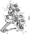
- FIG. 1 shows schematically a vehicle comprising a system for stabilisation according to one embodiment of the present invention.
- the vehicle is articulated and comprises a chassis that is generally denoted by reference number 1.
- the system comprises a rear wheel bogie 2 arranged at the chassis 1, whereby the rear wheel bogie 2 comprises a rigid, centrally mount pendulum shaft 4 designed to be rotated around rotary bearings 5 located at the centre of the pendulum shaft such that the pendulum shaft can oscillate around an axis 6 that extends parallel to the longitudinal direction or principal axis, denoted "CL", of the vehicle.
- the vehicle comprises further a forward wheel bogie 8 arranged at the chassis.
- the forward wheel bogie 8 and the rear wheel bogie 2 can be rotated, through their respective bogie arm 9 (bogie box) and a rotation joint 10 located at the centre of this arm, around the relevant horizontal axis 12, 13 that extends essentially perpendicular to the longitudinal direction of the vehicle.
- the chassis 1 comprises a forward frame and a rear frame 14, 15, connected through an articulated joint 16.
- the articulated joint 16 rotates around a vertical axis.
- the forward frame 14 and the rear frame 15 can in this way rotate in a sideways direction relative to each other.
- the vehicle comprises control cylinders (not shown in the drawings) that are active at the articulated joint.
- the forward wheel bogie 8 is arranged at the forward frame 14 and the rear wheel bogie 2 is arranged at the rear frame 15.
- a cabin 17 and a crane 18 are arranged at a tipping arrangement 20 at the forward frame 14 of the chassis.
- the tipping arrangement 20 comprises first and second hydraulic tipping actuators 22A, 22B that make it possible to rotate the cabin 17 and the crane 18 around a horizontal axis 23 parallel to the longitudinal direction of the vehicle and, in the embodiment described here, also around a horizontal axis 24 essentially perpendicular to the longitudinal direction of the vehicle.
- the tipping arrangement 20, which is located at the forward frame 14, comprises further a rotating disk 26 on rotary bearings 27, which make it possible to rotate the crane 18 and the cabin 17 around a vertical axis 28.
- a hydraulic stabilisation arrangement 30 comprising first and second hydraulic stabilisation actuators 31A, 31B is arranged at the rear wheel bogie 2.
- the first and second stabilisation actuators 31A, 31B follow the motions of the pendulum arm and in this way improve comfort when the vehicle is driven over irregular ground.
- the first and second stabilisation actuators 31A, 31B are arranged in fluid-mediated connection with the said first and second hydraulic tipping actuators 22A, 22B, and in this way are arranged to be controlled on the basis of the pressure at the tipping actuators.
- the tipping actuators 22A, 22B be parallel and arranged one on each side of the centre line or longitudinal axis of the vehicle. It is appropriate that the first and second stabilisation actuators 31A, 31B be arranged in a parallel manner one on each side of the principal axis of the vehicle.
- the stabilisation actuators 31A, 31B are arranged in fluid-mediated connection with corresponding tipping actuators 22A, 22B on the same side of the central principal axis of the vehicle. This is to say that the first stabilisation actuator 31A is in fluid-transfer connection with the corresponding first tipping actuator 22A on one side and, in a corresponding manner, the second stabilisation actuator 31B is in fluid-transfer connection with a second tipping actuator 22B on the other side.
- the said first stabilisation actuator 31A and the first tipping actuator 22A are arranged in fluid-mediated connection, while the said second stabilisation actuator 31B and the second tipping actuator 22B are arranged in fluid-mediated connection, whereby the stabilisation actuators are controlled on the basis of the pressure at the tipping actuators.
- the tipping arrangement 20 and the stabilisation arrangement 30 are described in more detail in association with Figures 2 , 3 and 4 .
- FIG 2 shows schematically a vehicle 1 comprising a system 100 for stabilisation according to one embodiment of the present invention.
- the vehicle is shown in a view from above.
- the vehicle is designed as described in Figure 1 .
- the crane 18 being arranged at a tipping arrangement 20 comprising a rotating disk 26 on rotary bearings 27, it is possible that the crane be rotated around a vertical axis 28, outwardly towards the sides relative to the centre line CL of the vehicle.
- the position of the crane 18 can be defined by an angle of rotation relative to a normal position parallel to the centre line CL of the vehicle.
- the position directly ahead in the principal direction of travel of the vehicle, parallel to the centre line CL of the vehicle can be said to constitute a normal position and thus an angle of rotation of 0°.
- a torque that influences the tipping arrangement 20 is generated depending on the position of the crane 18 relative to the centre line CL of the vehicle such that the tipping arrangement is rotated either around the horizontal axis 23 parallel to the centre line of the vehicle or around the horizontal axis 24 essentially perpendicular to the centre line of the vehicle.
- the torque that arises depends on the load and position of the crane. If the torque that is generated by the crane 18 is not counteracted, i.e.
- the vehicle tends to tip over in the direction of the torque.
- the torque leads to the tipping arrangement 20 being rotated around a horizontal axis 23, whereby the hydraulic tipping actuators 22A, 22B and their internal pressure are influenced. Since the stabilisation actuators 31A, 31B are in fluid-mediated connection with the tipping actuators 22A, 22B, also the pressure at the stabilisation actuators will be changed when the pressure at the tipping actuators is changed.
- the stabilisation actuators 31A, 31B are controlled on the basis of the pressure at the tipping actuators that is caused by the crane.
- the stabilisation actuators 31A, 31B are arranged in fluid-mediated connection with the tipping actuators 22A, 22B, such that the pressure at the stabilisation actuators leads to a force that counteracts the torque that has arisen.
- a hydraulic load-sensitive stabilisation arrangement is in this way achieved that generates a counteracting force that is directly proportional to the torque that has arisen.
- a stabilisation system for a vehicle is in this way achieved that is effective and safe and that can be used while the vehicle is being driven.
- the present system is hydraulically load-sensitive and uses a tipping arrangement 20 that senses the actual or true displacement of the centre of gravity that is generated as a consequence of the rotational position of the crane 18 and measures the forces and torques that arise in the rotating disk 26 and rotary bearings 27, i.e. in the interface between an upper part supporting the driver's cabin and the crane that can rotate freely relative to a lower carriage or a chassis at the vehicle, significant advantages over prior art technology are obtained.
- the tipping torque of the crane 18 that is created and the counteraction of the pendulum bogie 2 are directly proportional to the tipping torque (the load) of the crane.
- the system is hydraulically load-sensitive. If the crane 18 is rotated in the opposite direction, the counteraction and the pressure will be the opposite.
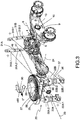
- FIG 3 shows schematically a system for the stabilisation of a vehicle according to the present invention.
- the vehicle 1 is designed in the manner that is described in Figures 1 and 2 , whereby the crane 18 is positioned directly forwards in the principal direction of travel of the vehicle.
- the crane 18 has a position with an angle of rotation of 0°, which is illustrated in the drawing with an arrow.
- the tipping arrangement 20 comprises a tipping plate 25 that is arranged at a tipping link 35 including a unit with the aid of which the tipping plate 25 is suspended in a cardan manner and rotationally displaceable around two perpendicular axes including the said horizontal axis 23, parallel to the longitudinal direction of the vehicle, and the said horizontal axis 24, perpendicular to the longitudinal direction of the vehicle.
- the said rotating disk 26 and the rotary bearings 27 are arranged at the tipping plate 25.
- the first and second tipping actuators 22A, 22B thus allow, through the tipping link 35, the tipping plate 25 to be rotated around the said horizontal axis 23 parallel to the longitudinal direction of the vehicle and around the said horizontal axis 24 perpendicular to the longitudinal direction of the vehicle.
- Each tipping actuator 22A, 22B is constituted by a double-action hydraulic cylinder comprising a piston 36 and a piston rod 37, whereby first and second chambers 22A:1, 22B:1; 22A:2, 22B:2, respectively, are formed on each side of the piston 36.
- the first chamber and the second chamber have variable volumes that depend on the position of the piston in the cylinder.
- the tipping actuators 22A, 22B are so arranged that the second chamber 22A:2; 22B:2, the piston rod chamber, is arranged closest to the crane 18, while the first chamber 22A:1; 22B:1, the piston chamber, is arranged closest to the ground over which the vehicle is being driven.
- the tipping actuators 22A, 22B may be known also as "tipping cylinders".
- a tipping actuator 22A, 22B When a tipping actuator 22A, 22B is compressed or pressed into a withdrawn condition, the piston 36 moves in a direction such that the first chamber 22A:1; 22B:1 is reduced and the second chamber 22A:2; 22B:2 is expanded.
- a high pressure is achieved in the first chamber relative to the pressure at the second chamber 22A:2; 22B:2, which is, in this way, lower.
- the first chamber 22A:1; 22B:1 is expanded and the second chamber 22A:2; 22B:2 is reduced when the tipping cylinder takes up an extended condition.
- a high pressure is in this way caused at the second chamber 22A:2; 22B:2 relative to the pressure at the first chamber 22A:1; 22B:1.
- Each stabilisation actuator 31A, 31B is constituted in a similar manner by a double-action hydraulic cylinder comprising a piston 46 and a piston rod 47, whereby a first chamber 31A:1, 31B:1, i.e. a piston chamber, is formed at a first side of the piston, and a second chamber 31A:2, 31B:2 enclosing the piston rod, i.e. a piston rod chamber, is formed at a second side of the piston.
- the first chamber 31A:1, 31B:1 and the second chamber 31A:2, 31B:2 have variable volumes that depend on the position of the piston 46 in the cylinder.
- the stabilisation actuators 31A, 31B are so arranged that their second chambers 31A:2, 31B:2 are located closest to the ground on which the vehicle is being driven.
- the stabilisation actuators may be known also as "stabilisation cylinders".
- the stabilisation actuators 31A, 31B are so arranged that when a stabilisation actuator is compressed or pressed into a withdrawn condition, the first chamber 31A:1, 31B:1 is reduced and the second chamber 31A:2, 31B:2 is expanded. In a corresponding manner, the first chamber 31A:1, 31B:1 is expanded and the second chamber is reduced when the stabilisation cylinder takes up an extended condition.
- the cylinder cross-sectional areas of the stabilisation actuators 31A, 31B are considerably smaller than the cylinder areas of the tipping actuators 22A, 22B.
- the piston areas of the stabilisation actuators 31A, 31B are as a consequence considerably smaller than the piston areas of the tipping actuators 22A, 22B.
- the motion at the tipping arrangement 20 will be smaller than the motion at the stabilisation arrangement 30.
- a change in pressure at the tipping actuators 22A, 22B thus leads to a larger displacement of the piston 46 and the piston rod 47 at the corresponding stabilisation actuator 31A, 31B than the effect that a change in pressure at the stabilisation actuators 31A, 31B has on the piston 36 and piston rod 37 of the tipping actuators.
- the first chamber 31A:1, 31B:1 at each stabilisation actuator 31A, 31B is arranged in fluid-mediated connection with the first chamber 22A:1; 22B:1 at the tipping actuator 22A, 22B that is arranged on the same side of the centre line of the vehicle, while the second chamber 31A:2, 31B:2 at each stabilisation actuator 31A, 31B is arranged in fluid-mediated connection with the second chamber 22A:2; 22B:2 at the tipping actuator 22A, 22B arranged on the same side.
- first and second stabilisation valves 40A, 40B are arranged in fluid-mediated connection with a tipping actuator 22A and a stabilisation actuator 31A, while the second stabilisation valve 40B is arranged in fluid-mediated connection with a second tipping actuator 22B.
- the stabilisation valve 40A, 40B can be arranged in connection to the first chamber 22A:1; 22B:1; 31A:1, 31B:1 at the relevant tipping actuator 22A, 22B and stabilisation actuator 31A, 31B. It is appropriate that the stabilisation valves 40A, 40B are constituted by electrically controlled valves. They are shown in the drawing in their non-activated, non current-carrying condition.
- a control unit (not shown in the drawings) be arranged in connection with the stabilisation valves, whereby the control unit can switch the stabilisation valves between their open condition and their closed condition.
- the stabilisation valves 40A, 40B are appropriately set in a current-carrying open condition.
- the first chamber 22A:1; 22B:1; 31A:1, 31B:1 at the relevant stabilisation actuator 31A, 31B is in fluid-mediated connection with the first chamber at the relevant tipping actuator 22A, 22B during transport, whereby the stabilisation actuators are continuously controlled on the basis of the pressure at the tipping actuators 22A, 22B.
- the stabilisation actuators 31A, 31B continuously generate in this way a force that counteracts the torque that is caused by the crane 18.
- FIG. 3 A condition is illustrated in Figure 3 in which the crane 18 is at an angle of rotation of 0° while the vehicle is being driven forwards or backwards.
- the position and load of the crane 18 lead in this case to a torque being generated, as will be realised if Figure 2 is studied.
- the torque influences the tipping arrangement 20 such that the tipping plate 25 is rotated forwards around the horizontal axis 24 that is essentially perpendicular to the centre line CL of the vehicle.
- the tipping actuators 22A, 22B are compressed.
- the first chamber 22A:1, 22B:1 at the relevant tipping actuator 22A, 22B is set under pressure and reduced in volume, whereby a high pressure is achieved at the relevant first chamber. This is illustrated by a plus symbol in the drawing.
- the second chamber 22A:2, 22B:2 at the relevant tipping actuator 22A, 22B is expanded, whereby a relatively low pressure at the relevant second chamber is achieved. This is illustrated by a minus symbol in the drawing.
- first chamber 31A:1; 31B:1 at the relevant stabilisation actuator 31A, 31B is arranged in fluid-mediated connection with the first chamber 22A:1; 22B:1 at the tipping actuators 22A, 22B, a high pressure is achieved also at the first chambers of the stabilisation actuators. This is illustrated in a similar manner by a plus symbol in the drawing.
- the pressure at the first chamber 31A:1, 31B:1 at the relevant stabilisation actuator 31A, 31B becomes high, the pressure influences the piston 46, and the first chamber 31A:1, 31B:1 at the said stabilisation actuator is expanded.
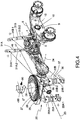
- Figure 4 illustrates schematically a condition in which the crane 18 is positioned directly to the side relative to the centre line CL of the vehicle.
- the crane 18 has been rotated to a position essentially at 90° to the left relative to the centre line of the vehicle.
- the crane When the vehicle is driven forwards or backwards and the crane has been rotated by 90° relative to the centre line of the vehicle, the crane generates a torque that is directed in the same direction as the crane, which will be realised if Figure 2 is studied.
- the torque influences the tipping arrangement 20 such that the tipping plate 25 is rotated around the horizontal axis 23 that is parallel to the centre line CL of the vehicle.
- the tipping arrangement 20 is thus in this way tilted to the left when viewed in the normal forwards direction of motion of the vehicle.
- the tipping actuator 22B that is arranged on the left side of the centre line CL is in this way compressed at the same time as the tipping actuator 22A on the right side of the centre line achieves an extended condition.
- the first chamber 22B:1 at the left tipping actuator 22B is in this way reduced and achieves a relatively high pressure.
- the volume of the second chamber 22A:2 at the right tipping actuator 22A is reduces, and achieves a high pressure. Since the pressure in the first chamber 22B:1 at the left tipping actuator 22B is high, the first chamber 31B:1 at the left stabilisation actuator 31B is exposed to a high pressure.
- the pressure at the first chamber 31B:1 at the left stabilisation actuator 31B increases, the pressure influences the piston, and the first chamber 31B:1 is expanded. A force is in this way created that is opposed to the force that influences the left tipping actuator 22B. Since the pressure at the second chamber 22A:2 at the right tipping actuator 22A is high, the second chamber 31A:2 at the right stabilisation actuator 31A will, in the same way, be exposed to a high pressure. The pressure in the second chamber 31A:2 at the right stabilisation actuator 31A influences in this way the piston 46 such that the first chamber 31A:1 is reduced.
- This fluid-mediated connection that operates with a relatively high pressure and lies between the opposite chambers of the said tipping actuators 22A, 22B and stabilisation actuators 31A, 31B is illustrated in the drawing by a solid line.
- a force is in this way created that is opposed to the force that influences the right tipping actuator 22A.
- the opposing forces to which the stabilisation actuators 31A, 31B give rise counteract the torque that influences the tipping arrangement 20.
- the counteracting forces of the stabilisation actuators 31A, 31B are directly proportional to the torque, and ensure in this way that the vehicle does not tip over in the direction of the crane.
- the present invention concerns also a method for the stabilisation of a vehicle that comprises a system for the stabilisation of a vehicle of the type that is described in Figures 3 and 4 .
- the method comprises the step a) to control the two stabilisation actuators 31A, 31B on the basis of the pressure at two tipping actuators 22A, 22B at the tipping arrangement 20 by ensuring that the stabilisation actuators are in fluid-mediated connection with the tipping actuators, whereby the tipping actuators are arranged in connection with the tipping plate 25, such that the tipping plate can be rotated, relative to the chassis, around a horizontal axis 23, 24.
- the method concern a method for the stabilisation of a vehicle in which the vehicle comprises a chassis 1 with a forward wheel bogie 8 and a rear wheel bogie 2.
- the vehicle comprises further a crane that is arranged at the tipping arrangement 20.
- the vehicle be further equipped with a cabin 17 that also is arranged at the tipping arrangement 20.
- the chassis 1 of the vehicle may be constituted by a forward frame 14 and a rear frame 15, whereby the forward wheel bogie is arranged at the forward frame and the rear wheel bogie is arranged at the rear wheel bogie.
- the tipping arrangement 20 be arranged at the forward frame 14 of the chassis and that the stabilisation arrangement 30 be therefore arranged at the rear frame 15.
- Each tipping actuator 22A, 22B may be constituted by a double-action cylinder comprising a piston 36 and a piston rod 37, such that a first chamber 22A:1, 22B:1 is formed at a first side of the piston and a second chamber 22A:2, 22B:2, which encloses the piston rod 37, is formed at a second side of the piston.
- Each stabilisation actuator 31A, 31B may in the same way be constituted by a double-action cylinder comprising a piston 46 and a piston rod 47, such that a first chamber 31A:1, 31B:1 is formed at a first side of the piston and a second chamber 31A:2, 31B:2, which encloses the piston rod, is formed at a second side of the piston.
- the first chamber 31A:1; 31B:1 at the relevant stabilisation actuator 31A, 31B may be placed in fluid-mediated connection with the first chamber 22A:1, 22B:1 at the relevant tipping actuator 22A, 22B, and the second chamber 31A:2, 31B:2 at the relevant stabilisation actuator 31A, 31B in fluid-mediated connection with the second chamber 22A:2; 22B:2 at the relevant tipping actuator 22A, 22B.
- first chamber 31A:1 at one of the stabilisation actuators 31A is in fluid-mediated connection with the first chamber 22A:1 at one of the tipping actuators 22A
- first chamber 31B:1 at the second stabilisation actuator 31B is in fluid-mediated connection with the first chamber 22B:1 at the second tipping actuator 22B.
- the said interacting stabilisation actuators 31A and 31B and tipping actuators 22A and 22B are arranged for each circuit one on each side of the centre line of the vehicle and in fluid-mediated connection with each other.
- the method may comprise to set two, first and second, stabilisation valves 40A, 40B to an open condition, whereby each stabilisation valve is arranged in fluid-mediated connection with the relevant stabilisation actuator 31A, 31B and the relevant tipping actuator 22A, 22B. It is appropriate that each stabilisation valve 40A, 40B be arranged when in its current-carrying condition to be in fluid-mediated connection with the first chamber 31A:1, 31B:1 at a stabilisation actuator 31A, 31B and a tipping actuator 22A, 22B.
- the second chamber 31A:2, 31B:2 at the relevant stabilisation actuator 31A, 31B be always in fluid-mediated connection with a tipping actuator 22A, 22B, without it being required that a stabilisation valve 40A, 40B be opened. It may be conceived as an alternative that the stabilisation valves 40A, 40B be arranged in fluid-mediated connection with the relevant second chambers 22A:2, 22B:2; 31A:2, 31B:2 of the stabilisation actuators 31A, 31B and tipping actuators 22A, 22B. It is appropriate that the stabilisation valves be controlled by an electronic control unit.
- the method may comprise the step b) to lock the stabilisation arrangement 30 by stopping the fluid-mediated connection between the first chambers 31A:1, 31B:1 and/or second chambers of the stabilisation actuators 31A, 31B and the first chambers 22A:1, 22B:1 and/or second chambers of the tipping actuators 22A, 22B. It may be desirable in special operating conditions, for example when the vehicle is stationary or is switched off, to lock the stabilisation arrangement 30 in order to maintain the counteracting force from the stabilisation actuators.
- the stabilisation arrangement be locked through the control unit setting the stabilisation valves to a normal condition in which no current flows, as is shown in Figure 5 , when the vehicle is switched off.
Landscapes
- Engineering & Computer Science (AREA)
- Mechanical Engineering (AREA)
- Chemical & Material Sciences (AREA)
- Combustion & Propulsion (AREA)
- Transportation (AREA)
- Physics & Mathematics (AREA)
- Fluid Mechanics (AREA)
- Vehicle Body Suspensions (AREA)
Description
- The present invention concerns a system for stabilizing a vehicle according to the introduction to
claim 1. The invention concerns also a method for stabilizing a vehicle according to the introduction to claim 14 and a vehicle according to claim 11. - Vehicles today, in particular terrain-going vehicles, are often driven on uneven ground and may impact impediments of various types. In order to deal with such irregularities and impediments while maintaining comfort and without the vehicle tipping over, it is important that sufficient contact between the wheels of the vehicle and the ground is ensured. Vehicles are, therefore, often designed with wheel bogies that cause the wheels to follow irregularities of the ground. A wheel bogie is a supplementary chassis that can be rotated relative to the principal chassis or frame of the vehicle. A wheel bogie normally has four wheels, which by means of wheel-supporting pendulum arms spread the load of the vehicle onto a greater number of axles and reduce the axle pressure, increase the load-bearing capacity, and improve the vehicle's handling when taking curves. A wheel bogie allows rotation around an axis that is parallel to the longitudinal direction of the vehicle and, in particular in the case of terrain-going vehicles, in combination with the ability to rotate around an axis that is perpendicular to the longitudinal direction of the vehicle. The pendulum arms may, as one alternative, be individually mounted to rotate, i.e. jointed at bearings at one of the ends, or they may be of a rigid, centrally mounted type consisting of a pendulum arm, such as, for example, a pendulum shaft designed to be rotated around a rotary bearing located at the centre of the pendulum shaft.
- Terrain-going vehicles, such as forestry machines, comprise a crane with a crane arm that can be extended far from the vehicle and at the free end of which a tool, such a gripper or a harvester, can be attached. The crane and its load, which is located at the farthest extent of the arm, constitute a significant part of the vehicle and influence the position of its centre of gravity when the crane arm is extended from the vehicle. This leads to a torque that influences the vehicle in different directions, depending on the rotational position of the crane in the horizontal plane and its extension from the vehicle. Thus, if the crane is directed forwards, a torque is created in the forwards direction, while if the crane has been turned to one side a torque is created towards the side. In order to prevent the vehicle tipping over as a consequence of the torque that has arisen, the said torque must be counteracted and balanced, which takes place by means of a stabilisation arrangement. Such a stabilisation arrangement is particularly important when the vehicle is an articulated vehicle. An articulated vehicle comprises two chassis parts that are united with each other in a jointed manner, a forward frame and a rear frame that can be rotated by being set at an angle through a jointed waist, which makes the vehicle flexible and easy to manoeuvre. One disadvantage of articulated vehicles, however, is that such a vehicle is less stable when it is driven around a curve, since the centre of gravity of the vehicle is at the same time displaced.
- One disadvantage of prior art stabilisation arrangements is that they are designed to be used principally when the vehicle is stationary. A further disadvantage of prior art stabilisation arrangements is that they are based on static calculations based on a series of parameters that have been determined in advance, for example based on the rotational position of the crane in the horizontal plane. Since the displacement of the centre of gravity of a vehicle is influenced by forces and torques that are not only static but also dynamic, the counteracting forces that are calculated in order to balance the vehicle will not always correspond to the actual or true torque that arises at the vehicle due to the displacement of the centre of gravity that occurs. The latter is particularly troublesome when the vehicle is in motion and subject to dynamic and more or less unpredictable forces and torques that do not necessarily depend on the rotational position of the crane.
- Document
SE 532683 WO2013178886 describes a system to stabilise a forestry machine where the torque that acts on a part of the chassis is determined, after which the magnitude and direction of a counteracting torque are determined. DocumentUS4580797 discloses a self-leveling cross-country vehicle provided with a carrier frame which is pivotally mounted to the vehicle frame about the longitudinal and transverse axes. Hydraulic cylinders are connected to each side of the mounting shafts of the carrier frame which are connected to a hydraulic pressure circuit. The wheels of the vehicle are mounted on axles which is provided with a hydraulic piston also connected to the hydraulic pressure circuit. The up and down movement of the axles as the vehicle travels over the ground actuates the hydraulic piston which levels the carrier frame with respect to the ground. - Despite the prior art solutions within the technical area, there is a requirement to achieve a system for the stabilisation of vehicles that is effective and safe, that can be applied when the vehicle is being driven, and that minimises the risk of the vehicle tipping over.
- One purpose of the present invention is to provide a system for the stabilisation of a vehicle that is effective and safe and that minimises the risk of the vehicle tipping over.
- A further purpose of the invention is to provide a system for the stabilisation of a vehicle that can be used when the vehicle is being driven.
- A further purpose of the present invention is to provide a method for the stabilisation of a vehicle that is effective and safe and that minimises the risk of the vehicle tipping over.
- A further purpose of the invention is to provide a method for the stabilisation of a vehicle that can be used when the vehicle is being driven.
- Certain of these purposes are achieved with a system for the stabilisation of a vehicle according to
claim 1. Other purposes are achieved with a vehicle according to claim 11. Other purposes are achieved with a method according toclaim 14. Advantageous embodiments are specified in the non-independent claims. - According to one aspect of the invention, a system is provided for the stabilisation of a vehicle, comprising a rear wheel bogie arranged at the chassis of the vehicle, whereby the rear wheel bogie comprises a pendulum shaft that can be rotated around an axis that extends parallel to the longitudinal direction of the vehicle; a tipping arrangement arranged at the chassis on which a crane is arranged, whereby the tipping arrangement comprises a rotating disk arranged on rotary bearings such that the rotating disk and thus also the crane can rotate around a vertical axis; and a hydraulic stabilisation arrangement comprising two stabilisation actuators, arranged at the rear wheel bogie. The tipping arrangement further comprises two hydraulic tipping actuators arranged in connection with the rotating disk, such that the rotating disk can be rotated around a horizontal axis relative to the chassis, whereby the stabilisation actuators are arranged in fluid-mediated connection with the tipping actuators and are in this way arranged to be controlled on the basis of the pressure at the tipping actuators.
- The term "vertical axis" is here used to denote an axis that extends essentially perpendicular to the ground on which the vehicle is being driven. The term "horizontal axis" is here used to denote an axis that extends essentially parallel to the ground on which the vehicle is being driven. Thus, a vertical axis extends essentially perpendicular to a horizontal axis. A horizontal axis may be an axis that extends parallel to the longitudinal or principal axis of the vehicle.
- It is preferable that the tipping actuators be arranged such that the rotating disk can be rotated around a horizontal axis parallel to the longitudinal direction of the vehicle and/or in a cardan manner around a horizontal axis essentially perpendicular to the longitudinal direction of the vehicle. It is preferable that the tipping arrangement comprise a tipping plate that is arranged at a tipping link. The rotating disk and the rotary bearings are arranged at the tipping plate.
- Through the crane being arranged at a tipping arrangement comprising a rotating disk on rotary bearings, it is possible for the crane to be rotated around a vertical axis, outwardly towards the sides relative to the centre line of the vehicle. Thus the position of the crane can be defined by an angle of rotation relative to a normal position parallel to the centre line of the vehicle. It is appropriate that the position directly ahead of the principal direction of travel of the vehicle, parallel to the centre line of the vehicle, constitute the normal position and thus an angle of rotation of 0°. Thus, when the crane is directed directly backwards, it is positioned at an angle of rotation of 180°. Thus, when the crane is directed directly to the side, it is positioned with an angle of rotation of 90° or 270°, to the right or left relative to the centre line of the vehicle. A torque that influences the tipping arrangement is obtained depending on the position of the crane relative to the centre line of the vehicle. The torque that is obtained depends on the load and position of the crane. The torque leads to the tipping arrangement being rotated around a horizontal axis, whereby the hydraulic tipping actuators and their pressure are influenced. Since the stabilisation actuators are in fluid-mediated connection with the tipping actuators, the pressure at the stabilisation actuators will be changed when the pressure at the tipping actuators is changed. Thus, the stabilisation actuators are controlled on the basis of the pressure at the tipping actuators that is caused by the crane. In this way, an adaptive and load-sensitive hydraulic stabilisation arrangement is obtained that senses the actual torques that arise. A system for the stabilisation of a vehicle that is effective and safe and that can be used while the vehicle is being driven is in this way achieved.
- Due to the fact that the present system uses a tipping arrangement that senses the actual or true displacement of the centre of gravity by measuring the forces and torques that arise in the rotating disk, i.e. in the interface between an upper part that supports a driver's cabin and a crane that can rotate freely relative to a lower carriage or chassis, a number of significant advantages over prior art technology are obtained. While the prior art technology, as described in, for example,
SE 532683 - It is appropriate that a cabin be arranged at the tipping arrangement. The cabin and the crane will in this way move together in the same direction.
- An embodiment of the invention will be described below in more detail with reference to the attached drawings, of which:
-
Figure 1 shows a view in perspective of a vehicle equipped with a crane and comprising a system for stabilisation according to the invention; -
Figure 2 shows a view from above of the vehicle inFigure 1 with a crane that is a component of the vehicle set into several rotational positions in the horizontal plane; -
Figure 3 shows schematically a hydraulic circuit for the stabilisation of a vehicle according to the invention, whereby the crane has been turned to a first rotational position at 0° to the principal axis of the vehicle and thus directed directly forwards in the normal direction of travel of the vehicle; and -
Figure 4 shows schematically a hydraulic circuit corresponding toFigure 3 but in a position in which the crane has been rotated to a second rotational position 270° to the principal axis of the vehicle and thus directed perpendicularly to the left, when seen in the normal direction of travel of the vehicle; and -
Figure 5 shows a hydraulic diagram of the system according to the invention for the stabilisation of a vehicle. -
Figure 1 shows schematically a vehicle comprising a system for stabilisation according to one embodiment of the present invention. The vehicle is articulated and comprises a chassis that is generally denoted byreference number 1. With reference also toFigures 3 and4 , the system comprises arear wheel bogie 2 arranged at thechassis 1, whereby therear wheel bogie 2 comprises a rigid, centrally mountpendulum shaft 4 designed to be rotated aroundrotary bearings 5 located at the centre of the pendulum shaft such that the pendulum shaft can oscillate around anaxis 6 that extends parallel to the longitudinal direction or principal axis, denoted "CL", of the vehicle. The vehicle comprises further aforward wheel bogie 8 arranged at the chassis. Two pairs of wheels are arranged at each wheel bogie, one on each side of the longitudinal axis of the vehicle. Theforward wheel bogie 8 and therear wheel bogie 2 can be rotated, through their respective bogie arm 9 (bogie box) and a rotation joint 10 located at the centre of this arm, around the relevanthorizontal axis chassis 1 comprises a forward frame and arear frame forward frame 14 and therear frame 15 can in this way rotate in a sideways direction relative to each other. The vehicle comprises control cylinders (not shown in the drawings) that are active at the articulated joint. Theforward wheel bogie 8 is arranged at theforward frame 14 and therear wheel bogie 2 is arranged at therear frame 15. Acabin 17 and acrane 18 are arranged at atipping arrangement 20 at theforward frame 14 of the chassis. The tippingarrangement 20 comprises first and secondhydraulic tipping actuators cabin 17 and thecrane 18 around ahorizontal axis 23 parallel to the longitudinal direction of the vehicle and, in the embodiment described here, also around ahorizontal axis 24 essentially perpendicular to the longitudinal direction of the vehicle. The tippingarrangement 20, which is located at theforward frame 14, comprises further arotating disk 26 onrotary bearings 27, which make it possible to rotate thecrane 18 and thecabin 17 around avertical axis 28. A hydraulic stabilisation arrangement 30 comprising first and secondhydraulic stabilisation actuators rear wheel bogie 2. The first andsecond stabilisation actuators second stabilisation actuators hydraulic tipping actuators tipping actuators second stabilisation actuators stabilisation actuators corresponding tipping actuators first stabilisation actuator 31A is in fluid-transfer connection with the correspondingfirst tipping actuator 22A on one side and, in a corresponding manner, thesecond stabilisation actuator 31B is in fluid-transfer connection with asecond tipping actuator 22B on the other side. Or, in other words, the saidfirst stabilisation actuator 31A and thefirst tipping actuator 22A are arranged in fluid-mediated connection, while the saidsecond stabilisation actuator 31B and thesecond tipping actuator 22B are arranged in fluid-mediated connection, whereby the stabilisation actuators are controlled on the basis of the pressure at the tipping actuators. The tippingarrangement 20 and the stabilisation arrangement 30 are described in more detail in association withFigures 2 ,3 and4 . -
Figure 2 shows schematically avehicle 1 comprising a system 100 for stabilisation according to one embodiment of the present invention. The vehicle is shown in a view from above. The vehicle is designed as described inFigure 1 . Through thecrane 18 being arranged at atipping arrangement 20 comprising arotating disk 26 onrotary bearings 27, it is possible that the crane be rotated around avertical axis 28, outwardly towards the sides relative to the centre line CL of the vehicle. Thus the position of thecrane 18 can be defined by an angle of rotation relative to a normal position parallel to the centre line CL of the vehicle. The position directly ahead in the principal direction of travel of the vehicle, parallel to the centre line CL of the vehicle, can be said to constitute a normal position and thus an angle of rotation of 0°. Thus, when thecrane 18 is directed directly backwards, it is positioned at an angle of rotation of 180°. Thus, when thecrane 18 is directed to the side, directly to the right or left relative to the centre line CL of the vehicle, it is positioned at an angle of rotation of 90° or 270° (-90°). A torque that influences thetipping arrangement 20 is generated depending on the position of thecrane 18 relative to the centre line CL of the vehicle such that the tipping arrangement is rotated either around thehorizontal axis 23 parallel to the centre line of the vehicle or around thehorizontal axis 24 essentially perpendicular to the centre line of the vehicle. The torque that arises depends on the load and position of the crane. If the torque that is generated by thecrane 18 is not counteracted, i.e. not balanced by a counteracting force, the vehicle tends to tip over in the direction of the torque. The further away from the vehicle that the crane is extended, the greater will be the torque that is obtained, and the greater will be the risk that the vehicle tips over, if the torque is not counteracted. Thus the torque leads to thetipping arrangement 20 being rotated around ahorizontal axis 23, whereby thehydraulic tipping actuators stabilisation actuators tipping actuators stabilisation actuators stabilisation actuators tipping actuators tipping arrangement 20 that senses the actual or true displacement of the centre of gravity that is generated as a consequence of the rotational position of thecrane 18 and measures the forces and torques that arise in therotating disk 26 androtary bearings 27, i.e. in the interface between an upper part supporting the driver's cabin and the crane that can rotate freely relative to a lower carriage or a chassis at the vehicle, significant advantages over prior art technology are obtained. The tipping torque of thecrane 18 that is created and the counteraction of thependulum bogie 2 are directly proportional to the tipping torque (the load) of the crane. The system is hydraulically load-sensitive. If thecrane 18 is rotated in the opposite direction, the counteraction and the pressure will be the opposite. -
Figure 3 shows schematically a system for the stabilisation of a vehicle according to the present invention. Thevehicle 1 is designed in the manner that is described inFigures 1 and2 , whereby thecrane 18 is positioned directly forwards in the principal direction of travel of the vehicle. Thus, thecrane 18 has a position with an angle of rotation of 0°, which is illustrated in the drawing with an arrow. The tippingarrangement 20 comprises atipping plate 25 that is arranged at atipping link 35 including a unit with the aid of which thetipping plate 25 is suspended in a cardan manner and rotationally displaceable around two perpendicular axes including the saidhorizontal axis 23, parallel to the longitudinal direction of the vehicle, and the saidhorizontal axis 24, perpendicular to the longitudinal direction of the vehicle. The saidrotating disk 26 and therotary bearings 27 are arranged at thetipping plate 25. The first andsecond tipping actuators tipping link 35, the tippingplate 25 to be rotated around the saidhorizontal axis 23 parallel to the longitudinal direction of the vehicle and around the saidhorizontal axis 24 perpendicular to the longitudinal direction of the vehicle. - Each tipping
actuator piston 36 and apiston rod 37, whereby first andsecond chambers 22A:1, 22B:1; 22A:2, 22B:2, respectively, are formed on each side of thepiston 36. The first chamber and the second chamber have variable volumes that depend on the position of the piston in the cylinder. Thetipping actuators second chamber 22A:2; 22B:2, the piston rod chamber, is arranged closest to thecrane 18, while thefirst chamber 22A:1; 22B:1, the piston chamber, is arranged closest to the ground over which the vehicle is being driven. Thetipping actuators tipping actuator piston 36 moves in a direction such that thefirst chamber 22A:1; 22B:1 is reduced and thesecond chamber 22A:2; 22B:2 is expanded. When thefirst chamber 22A:1; 22B:1 is reduced, a high pressure is achieved in the first chamber relative to the pressure at thesecond chamber 22A:2; 22B:2, which is, in this way, lower. In a corresponding manner, thefirst chamber 22A:1; 22B:1 is expanded and thesecond chamber 22A:2; 22B:2 is reduced when the tipping cylinder takes up an extended condition. A high pressure is in this way caused at thesecond chamber 22A:2; 22B:2 relative to the pressure at thefirst chamber 22A:1; 22B:1. - Each
stabilisation actuator piston 46 and apiston rod 47, whereby afirst chamber 31A:1, 31B:1, i.e. a piston chamber, is formed at a first side of the piston, and asecond chamber 31A:2, 31B:2 enclosing the piston rod, i.e. a piston rod chamber, is formed at a second side of the piston. Thefirst chamber 31A:1, 31B:1 and thesecond chamber 31A:2, 31B:2 have variable volumes that depend on the position of thepiston 46 in the cylinder. Thestabilisation actuators second chambers 31A:2, 31B:2 are located closest to the ground on which the vehicle is being driven. The stabilisation actuators may be known also as "stabilisation cylinders". Thestabilisation actuators first chamber 31A:1, 31B:1 is reduced and thesecond chamber 31A:2, 31B:2 is expanded. In a corresponding manner, thefirst chamber 31A:1, 31B:1 is expanded and the second chamber is reduced when the stabilisation cylinder takes up an extended condition. - The cylinder cross-sectional areas of the
stabilisation actuators tipping actuators stabilisation actuators tipping actuators tipping arrangement 20 will be smaller than the motion at the stabilisation arrangement 30. A change in pressure at thetipping actuators piston 46 and thepiston rod 47 at the correspondingstabilisation actuator stabilisation actuators piston 36 andpiston rod 37 of the tipping actuators. - The
first chamber 31A:1, 31B:1 at eachstabilisation actuator first chamber 22A:1; 22B:1 at thetipping actuator second chamber 31A:2, 31B:2 at eachstabilisation actuator second chamber 22A:2; 22B:2 at thetipping actuator - As is shown in
Figure 5 , first andsecond stabilisation valves tipping actuator 22A and astabilisation actuator 31A, while thesecond stabilisation valve 40B is arranged in fluid-mediated connection with asecond tipping actuator 22B. Thestabilisation valve first chamber 22A:1; 22B:1; 31A:1, 31B:1 at therelevant tipping actuator stabilisation actuator stabilisation valves stabilisation valves first chamber 22A:1; 22B:1; 31A:1, 31B:1 at therelevant stabilisation actuator relevant tipping actuator tipping actuators stabilisation actuators crane 18. - A condition is illustrated in
Figure 3 in which thecrane 18 is at an angle of rotation of 0° while the vehicle is being driven forwards or backwards. The position and load of thecrane 18 lead in this case to a torque being generated, as will be realised ifFigure 2 is studied. The torque influences thetipping arrangement 20 such that the tippingplate 25 is rotated forwards around thehorizontal axis 24 that is essentially perpendicular to the centre line CL of the vehicle. When thetipping plate 25 is rotated around thehorizontal axis 24 in the direction of the torque, the tippingactuators first chamber 22A:1, 22B:1 at therelevant tipping actuator second chamber 22A:2, 22B:2 at therelevant tipping actuator first chamber 31A:1; 31B:1 at therelevant stabilisation actuator first chamber 22A:1; 22B:1 at thetipping actuators first chamber 31A:1, 31B:1 at therelevant stabilisation actuator piston 46, and thefirst chamber 31A:1, 31B:1 at the said stabilisation actuator is expanded. This fluid-mediated connection that operates with a relatively high pressure and lies between the saidtipping actuators stabilisation actuators pendulum shaft 4 will be rotated around therotary bearings 5 and thehorizontal axis 6 parallel to the centre line of the vehicle. When thefirst chambers 31A:1, 31B:1 of thestabilisation actuators rear wheel bogie 2 will follow the ground in a smooth and flexible manner. Since thecrane 18 is directed directly forwards in the principal direction of travel of the vehicle, the chassis is not influenced in the sideways direction and thus no counteracting force worthy of mention is achieved at thestabilisation actuators -
Figure 4 illustrates schematically a condition in which thecrane 18 is positioned directly to the side relative to the centre line CL of the vehicle. Thus, thecrane 18 has been rotated to a position essentially at 90° to the left relative to the centre line of the vehicle. When the vehicle is driven forwards or backwards and the crane has been rotated by 90° relative to the centre line of the vehicle, the crane generates a torque that is directed in the same direction as the crane, which will be realised ifFigure 2 is studied. The torque influences thetipping arrangement 20 such that the tippingplate 25 is rotated around thehorizontal axis 23 that is parallel to the centre line CL of the vehicle. The tippingarrangement 20 is thus in this way tilted to the left when viewed in the normal forwards direction of motion of the vehicle. Thetipping actuator 22B that is arranged on the left side of the centre line CL is in this way compressed at the same time as thetipping actuator 22A on the right side of the centre line achieves an extended condition. Thefirst chamber 22B:1 at theleft tipping actuator 22B is in this way reduced and achieves a relatively high pressure. At the same time, the volume of thesecond chamber 22A:2 at theright tipping actuator 22A is reduces, and achieves a high pressure. Since the pressure in thefirst chamber 22B:1 at theleft tipping actuator 22B is high, thefirst chamber 31B:1 at theleft stabilisation actuator 31B is exposed to a high pressure. When the pressure at thefirst chamber 31B:1 at theleft stabilisation actuator 31B increases, the pressure influences the piston, and thefirst chamber 31B:1 is expanded. A force is in this way created that is opposed to the force that influences theleft tipping actuator 22B. Since the pressure at thesecond chamber 22A:2 at theright tipping actuator 22A is high, thesecond chamber 31A:2 at theright stabilisation actuator 31A will, in the same way, be exposed to a high pressure. The pressure in thesecond chamber 31A:2 at theright stabilisation actuator 31A influences in this way thepiston 46 such that thefirst chamber 31A:1 is reduced. This fluid-mediated connection that operates with a relatively high pressure and lies between the opposite chambers of the saidtipping actuators stabilisation actuators right tipping actuator 22A. The opposing forces to which thestabilisation actuators tipping arrangement 20. The counteracting forces of thestabilisation actuators - The present invention concerns also a method for the stabilisation of a vehicle that comprises a system for the stabilisation of a vehicle of the type that is described in
Figures 3 and4 . - The method comprises the step a) to control the two
stabilisation actuators tipping actuators tipping arrangement 20 by ensuring that the stabilisation actuators are in fluid-mediated connection with the tipping actuators, whereby the tipping actuators are arranged in connection with the tippingplate 25, such that the tipping plate can be rotated, relative to the chassis, around ahorizontal axis - It is appropriate that the method concern a method for the stabilisation of a vehicle in which the vehicle comprises a
chassis 1 with aforward wheel bogie 8 and arear wheel bogie 2. The vehicle comprises further a crane that is arranged at thetipping arrangement 20. It is appropriate that the vehicle be further equipped with acabin 17 that also is arranged at thetipping arrangement 20. Thechassis 1 of the vehicle may be constituted by aforward frame 14 and arear frame 15, whereby the forward wheel bogie is arranged at the forward frame and the rear wheel bogie is arranged at the rear wheel bogie. It is appropriate that thetipping arrangement 20 be arranged at theforward frame 14 of the chassis and that the stabilisation arrangement 30 be therefore arranged at therear frame 15. - Each tipping
actuator piston 36 and apiston rod 37, such that afirst chamber 22A:1, 22B:1 is formed at a first side of the piston and asecond chamber 22A:2, 22B:2, which encloses thepiston rod 37, is formed at a second side of the piston. Eachstabilisation actuator piston 46 and apiston rod 47, such that afirst chamber 31A:1, 31B:1 is formed at a first side of the piston and asecond chamber 31A:2, 31B:2, which encloses the piston rod, is formed at a second side of the piston. - According to the method, the
first chamber 31A:1; 31B:1 at therelevant stabilisation actuator first chamber 22A:1, 22B:1 at therelevant tipping actuator second chamber 31A:2, 31B:2 at therelevant stabilisation actuator second chamber 22A:2; 22B:2 at therelevant tipping actuator first chamber 31A:1 at one of thestabilisation actuators 31A is in fluid-mediated connection with thefirst chamber 22A:1 at one of thetipping actuators 22A, and that thefirst chamber 31B:1 at thesecond stabilisation actuator 31B is in fluid-mediated connection with thefirst chamber 22B:1 at thesecond tipping actuator 22B. The said interactingstabilisation actuators tipping actuators - The method may comprise to set two, first and second,
stabilisation valves relevant stabilisation actuator relevant tipping actuator stabilisation valve first chamber 31A:1, 31B:1 at astabilisation actuator tipping actuator second chamber 31A:2, 31B:2 at therelevant stabilisation actuator tipping actuator stabilisation valve stabilisation valves second chambers 22A:2, 22B:2; 31A:2, 31B:2 of thestabilisation actuators tipping actuators - The method may comprise the step b) to lock the stabilisation arrangement 30 by stopping the fluid-mediated connection between the
first chambers 31A:1, 31B:1 and/or second chambers of thestabilisation actuators first chambers 22A:1, 22B:1 and/or second chambers of thetipping actuators stabilisation actuators tipping actuators stabilisation valve Figure 5 , when the vehicle is switched off.
Claims (19)
- A system for the stabilisation of a vehicle with a chassis (1), the chassis comprising a rear wheel bogie (2), with a pendulum shaft that can be rotated, through rotary bearings (4), around an axis (6) that extends parallel to the longitudinal direction (CL) of the vehicle; a tipping arrangement (20) arranged at the chassis, on which tipping arrangement a crane (18) is arranged, whereby the tipping arrangement further comprises a rotating disk (26) arranged on rotary bearings (27) on a tipping plate (25) such that the rotating disk, and thus also the crane, can rotate around a vertical axis (28); and a hydraulic stabilisation arrangement (30) comprising first and second hydraulic stabilisation actuators (31A, 31B) arranged at the rear wheel bogie (2), whereby:- the rear wheel bogie (2) comprises two pairs of wheels, one pair on each side of the longitudinal axis of the vehicle, the rear wheel bogie (2) can be rotated, through its bogie arm (9), and a rotation joint (10) located at the centre of the bogie arm, around an horizontal axis (13) that extends perpendicular to the longitudinal direction of the vehicle,- the tipping arrangement (20) further comprises first and a second hydraulic tipping actuators (22A, 22B) arranged in connection with the_tipping plate (25), wherein_the tipping plate (25) and thus the rotating disc (26) can be rotated relative to the chassis around a horizontal axis (23, 24), under a torque that is generated depending on the position of the crane (18) relative to the centre line CL,
whereby the said first stabilisation actuator (31A) and the first tipping actuator (22A) are arranged in fluid-mediated connection, and the said second stabilisation actuator (31B) and the second tipping actuator (22B are arranged in fluid-mediated connection, whereby the pressure at the stabilisation actuators (31A, 31B) are controlled on the basis of the pressure at the tipping actuators (22A, 22B) caused by the position of the crane. - The system according to claim 1, whereby the first and second tipping actuators (22A, 22B) are arranged one on each side of the longitudinal direction (CL) of the vehicle.
- The system according to claim 1 or 2, whereby the first and second stabilisation actuators (31A, 31B) are arranged one on each side of the longitudinal direction (CL) of the vehicle.
- The system according to claims 2 and 3, whereby the said first and second stabilisation actuators (31A, 31B) are arranged in fluid-mediated connection in a circuit with the corresponding first and second tipping actuators (22A, 22B), where the said first and second circuits are located one on each side of the longitudinal direction (CL) of the vehicle.
- The system according to any one of the preceding claims 1-4, whereby the first and second tipping actuators (22A, 22B) are so arranged that the rotating disk (25) arranged on the tipping plate (25) can be rotated around any one of the following axes: a horizontal axis (23) parallel to the longitudinal direction (CL) of the vehicle, a horizontal axis (24) perpendicular to the longitudinal direction (CL) of the vehicle, or in a cardan manner around two perpendicular axes including a combination of the said axes (23, 24).
- The system according to any one of the preceding claims 1-5, whereby a cabin (17) is arranged at the tipping arrangement (20).
- The system according to any one of the preceding claims 1-6, whereby each tipping actuator (22A, 22B) is constituted by a double-action cylinder comprising a piston (36) and a piston rod (37), whereby a first chamber (22A:1, 22B:1) is formed at a first side of the piston, and a second chamber (22A:2, 22B:2), which encloses the piston rod, is formed at a second side of the piston.
- The system according to any one of the preceding claims 1-7, whereby each stabilisation actuator (31A, 31B) is constituted by a double-action cylinder comprising a piston (46) and a piston rod (47), whereby a first chamber (31A:1, 31B:1) is formed at a first side of the piston, and a second chamber (31A:2, 31B:2), which encloses the piston rod, is formed at a second side of the piston.
- The system according to claims 7 and 8, whereby the first chamber (31A:1, 31B:1) at each stabilisation actuator (31A, 31B) is arranged in fluid-mediated connection with the first chamber (22A:1; 22B:1) at the tipping actuator (22A, 22B) that is arranged on the same side of the centre line (CL) of the vehicle, while the second chamber (31A2, 31B2) at each stabilisation actuator (31A, 31B) is arranged in fluid-mediated connection with the second chamber (22A:2; 22B:2) at the tipping actuator (22A, 22B) arranged on the same side.
- The system according to claim 5, wherein the tipping arrangement (20) comprises a tipping link (35) including a unit with the aid of which the tipping plate (25) is suspended in a cardan manner and rotationally displaceable around two perpendicular axes including the said horizontal axis (23), parallel to the longitudinal direction of the vehicle, and the said horizontal axis (24), perpendicular to the longitudinal direction of the vehicle.
- A vehicle, characterised in that it comprises a system according to any one of the preceding claims 1-10.
- The vehicle according to claim 11, whereby the vehicle is a terrain-going vehicle, in particular a forestry machine equipped with a crane.
- The vehicle according to claim 11 or 12, whereby the chassis (19) of the vehicle comprises a forward frame (14) and a rear frame (15) connected through an articulated joint (16), whereby the tipping arrangement (20) is arranged at the forward frame and the stabilisation arrangement (30) is arranged at the rear frame.
- A method for the stabilisation of a vehicle with a chassis (1) that has a system for the stabilisation of the vehicle, the system comprising a rear wheel bogie (2) arranged at the chassis of the vehicle, whereby the rear wheel bogie comprises a pendulum shaft (4) that can be rotated, through rotary bearings (5), around an axis (6) that extends parallel to the longitudinal direction (CL) of the vehicle; a tipping arrangement (20) arranged at the chassis on which a crane (18) is arranged, whereby the tipping arrangement comprises a rotating disk (26) arranged on rotary bearings (27) such that the rotating disk and thus also the crane can rotate around a vertical axis (28); and a hydraulic stabilisation arrangement (30) comprising first and second stabilisation actuators (31A, 31B), arranged at the rear wheel bogie, characterised by the step:
to select the rear wheel bogie (2) of the type that comprises two pairs of wheels, one on each side of the longitudinal axis of the vehicle, each pair of wheels is mounted on a boggiearm (9), and can be rotated through the bogie arm and a rotation joint (10) located at the centre of the bogie arm, around an horizontal axis (13) that extends perpendicular to the longitudinal direction of the vehicle, and
a) to control the first and second stabilisation actuators (31A, 31B) through measurement of the forces and torques that arise in the tipping arrangement (20). - The method according to claim 14, and further by the step that,
the control takes place on the basis of the pressure at first and second tipping actuators (22A, 22B) at the tipping arrangement (20) by ensuring that the stabilisation actuators are in fluid-mediated connection with the tipping actuators, and through tipping actuators being arranged in connection with the rotating disk (25), such that this can be rotated relative to the chassis (1) around a horizontal axis (23, 24). - The method according to claim 15, further comprising the steps; to constitute each tipping actuator (22A, 22B) by a double-action cylinder comprising a piston (36) and a piston rod (37), such that a first chamber (22A:1, 22B:1) is formed at a first side of the piston and a second chamber (22A:2, 22B:2), which encloses the piston rod, is formed at a second side of the piston, and each stabilisation actuator (31A, 31B) is constituted by a double-action cylinder comprising a piston (46) and a piston rod (47), such that a first chamber (31A:1, 31B:1) is formed at a first side of the piston and a second chamber (31A:2, 31B:2), which encloses the piston rod, is formed at a second side of the piston, to ensure that the first chamber (31A:1, 31B:1) at the relevant stabilisation actuator (31A, 31B) is in fluid-mediated connection with the first chamber (22A:1, 22B:1) at the relevant tipping actuator and that the second chamber (31A:2, 31B:2) at the relevant stabilisation actuator (31A, 31B) is in fluid-mediated connection with the second chamber (22A:2, 22B:2) at the relevant tipping actuator (22A, 22B).
- The method according to claim 15 or 16, further comprising the step to set first and second stabilisation valves (40A, 40B) to an open condition, whereby each stabilisation valve establishes fluid-mediated connection between a stabilisation actuator (31A, 31B) and a tipping actuator (22A, 22B).
- The method according to any one of claims 15-16, whereby the method comprises the further step to:
b) lock the stabilisation arrangement by stopping the fluid-mediated connection between the first chambers (31A:1, 31B:1) of the stabilisation actuators (31A, 31B) and the first chambers (22A:1, 22B:1) of the tipping actuators (22A, 22B), or between the second chambers (31A:2, 31B:2) of the stabilisation actuators (31A, 31B) and the second chambers (22A:2, 22B:2) of the tipping actuators (22A, 22B). - The method according to claim 18, in which step b) comprises the setting of first and second stabilisation valves (40A, 40B) to a closed condition, whereby each stabilisation valve is arranged in fluid-mediated connection with a stabilisation actuator (31A, 31B) and a tipping actuator (22A, 22B).
Priority Applications (1)
| Application Number | Priority Date | Filing Date | Title |
|---|---|---|---|
| PL16821727T PL3317166T3 (en) | 2015-07-03 | 2016-06-08 | Systems for stabilizing a vehicle and method for stabilizing a vehicle |
Applications Claiming Priority (2)
| Application Number | Priority Date | Filing Date | Title |
|---|---|---|---|
| SE1550960A SE540556C2 (en) | 2015-07-03 | 2015-07-03 | Vehicle stabilization system and vehicle stabilization procedure |
| PCT/SE2016/050546 WO2017007393A1 (en) | 2015-07-03 | 2016-06-08 | Systems for stabilizing a vehicle and method for stabilizing a vehicle |
Publications (3)
| Publication Number | Publication Date |
|---|---|
| EP3317166A1 EP3317166A1 (en) | 2018-05-09 |
| EP3317166A4 EP3317166A4 (en) | 2019-02-20 |
| EP3317166B1 true EP3317166B1 (en) | 2020-07-29 |
Family
ID=57685540
Family Applications (1)
| Application Number | Title | Priority Date | Filing Date |
|---|---|---|---|
| EP16821727.1A Active EP3317166B1 (en) | 2015-07-03 | 2016-06-08 | Systems for stabilizing a vehicle and method for stabilizing a vehicle |
Country Status (10)
| Country | Link |
|---|---|
| US (1) | US10543816B2 (en) |
| EP (1) | EP3317166B1 (en) |
| AU (1) | AU2016291103B2 (en) |
| BR (1) | BR112017025649B1 (en) |
| CA (1) | CA2987573C (en) |
| ES (1) | ES2827777T3 (en) |
| PL (1) | PL3317166T3 (en) |
| RU (1) | RU2709319C2 (en) |
| SE (1) | SE540556C2 (en) |
| WO (1) | WO2017007393A1 (en) |
Families Citing this family (3)
| Publication number | Priority date | Publication date | Assignee | Title |
|---|---|---|---|---|
| WO2019116192A1 (en) * | 2017-12-11 | 2019-06-20 | Jacques Tranchero | Crane comprising a steering system |
| CN112144878A (en) * | 2019-06-28 | 2020-12-29 | 河北雷萨重型工程机械有限责任公司 | pump truck |
| DE102021122189A1 (en) | 2021-08-26 | 2023-03-02 | Hohenloher Spezial-Maschinenbau GmbH & Co. KG | Forestry vehicle with crane |
Family Cites Families (19)
| Publication number | Priority date | Publication date | Assignee | Title |
|---|---|---|---|---|
| US3349932A (en) * | 1963-08-02 | 1967-10-31 | Wagner Mfg Inc | Side dump loader |
| PL74598B2 (en) * | 1972-11-04 | 1974-12-31 | Fabryka Maszyn Budowlanychpo | |
| NL7508091A (en) * | 1975-07-08 | 1977-01-11 | Lely Nv C Van Der | TRACTOR. |
| SU856887A1 (en) * | 1979-12-18 | 1981-08-23 | Московский Автомобильно-Дорожный Институт | Method and apparatus for maintaining vehicle stability |
| SE451189B (en) | 1983-08-05 | 1987-09-14 | Umea Mekaniska Ab | DEVICE FOR CLEANING VEHICLES OR MACHINES |
| US4823852A (en) * | 1987-02-05 | 1989-04-25 | Allied Systems Company | Tree feller-buncher |
| FR2765912B1 (en) * | 1997-07-11 | 1999-12-17 | Tamrock Secoma Sa | WHEEL MOUNTED DRILL WITH ARTICULATED CHASSIS |
| DE29802248U1 (en) * | 1998-02-10 | 1998-06-10 | Michels GmbH & Co KG, 47608 Geldern | Crane supported on a chassis of an all-terrain vehicle |
| US6158539A (en) * | 1998-09-24 | 2000-12-12 | Risley Enterprises Ltd. | Levelling system and method for off-road vehicles |
| FI109531B (en) * | 2000-03-16 | 2002-08-30 | Timberjack Oy | Cabin construction for a working machine |
| US6241263B1 (en) * | 2000-04-25 | 2001-06-05 | Caterpillar Inc. | Tilt mechanism for adjusting position of an upper body assembly relative to an undercarriage assembly of a feller buncher |
| IT1319455B1 (en) * | 2000-06-29 | 2003-10-10 | Dana Italia Spa | DEVICE FOR THE DYNAMIC STABILITY CONTROL OF AN INDUSTRIAL VEHICLE. |
| WO2008016310A1 (en) * | 2006-07-31 | 2008-02-07 | Felix Edward Joseph Rust | Tilt apparatus and method for operating it |
| US7694772B1 (en) * | 2007-08-03 | 2010-04-13 | M-B Companies Inc. | Forward cab articulated tractor |
| KR100956995B1 (en) * | 2007-11-07 | 2010-05-11 | 볼보 컨스트럭션 이키프먼트 홀딩 스웨덴 에이비 | Leveling device for forest equipment and excavators |
| FI121705B (en) * | 2007-11-29 | 2011-03-15 | John Deere Forestry Oy | Procedure and system for stabilizing a vehicle |
| KR100967214B1 (en) * | 2007-12-12 | 2010-07-07 | 볼보 컨스트럭션 이키프먼트 홀딩 스웨덴 에이비 | Leveling control system of heavy equipment and its control method |
| RU2728111C2 (en) * | 2012-01-31 | 2020-07-28 | Джой Глобал Серфейс Майнинг Инк | Digging unit for cable excavator and digging tool for rope excavator (versions) |
| FI124565B (en) * | 2012-05-31 | 2014-10-15 | Ponsse Oyj | Stabilization of forestry work unit |
-
2015
- 2015-07-03 SE SE1550960A patent/SE540556C2/en unknown
-
2016
- 2016-06-08 US US15/741,464 patent/US10543816B2/en active Active
- 2016-06-08 AU AU2016291103A patent/AU2016291103B2/en active Active
- 2016-06-08 RU RU2018103885A patent/RU2709319C2/en active
- 2016-06-08 WO PCT/SE2016/050546 patent/WO2017007393A1/en not_active Ceased
- 2016-06-08 BR BR112017025649-5A patent/BR112017025649B1/en active IP Right Grant
- 2016-06-08 EP EP16821727.1A patent/EP3317166B1/en active Active
- 2016-06-08 ES ES16821727T patent/ES2827777T3/en active Active
- 2016-06-08 CA CA2987573A patent/CA2987573C/en active Active
- 2016-06-08 PL PL16821727T patent/PL3317166T3/en unknown
Non-Patent Citations (1)
| Title |
|---|
| None * |
Also Published As
| Publication number | Publication date |
|---|---|
| CA2987573C (en) | 2023-08-22 |
| ES2827777T3 (en) | 2021-05-24 |
| EP3317166A4 (en) | 2019-02-20 |
| RU2018103885A (en) | 2019-08-05 |
| AU2016291103A1 (en) | 2018-01-18 |
| RU2709319C2 (en) | 2019-12-17 |
| BR112017025649A2 (en) | 2018-08-07 |
| SE1550960A1 (en) | 2017-01-04 |
| US10543816B2 (en) | 2020-01-28 |
| RU2018103885A3 (en) | 2019-10-29 |
| PL3317166T3 (en) | 2020-12-28 |
| EP3317166A1 (en) | 2018-05-09 |
| AU2016291103B2 (en) | 2020-11-26 |
| WO2017007393A1 (en) | 2017-01-12 |
| BR112017025649B1 (en) | 2023-04-04 |
| US20180229695A1 (en) | 2018-08-16 |
| CA2987573A1 (en) | 2017-01-12 |
| SE540556C2 (en) | 2018-10-02 |
Similar Documents
| Publication | Publication Date | Title |
|---|---|---|
| FI125426B (en) | Arrangement and method for enabling rotation of a vehicle bogie or roller axle and chassis | |
| EP2856099B1 (en) | Stabilizing of forest work unit | |
| US9956842B2 (en) | System and method for controlling stability of milling machines | |
| EP3595961B1 (en) | Suspension device for tracked vehicles | |
| CA2987573C (en) | Systems for stabilizing a vehicle and method for stabilizing a vehicle | |
| SE537571C2 (en) | Apparatus for adjusting the ground pressure of an off-road motor vehicle and an off-road motor vehicle equipped with such a device | |
| EP3507173B1 (en) | Assembly and method for enabling rotational motion in a vehicle or mobile working machine | |
| FI121705B (en) | Procedure and system for stabilizing a vehicle | |
| EP3169538A1 (en) | A wheel suspension device | |
| CA2852288C (en) | Rear suspension for swather tractor | |
| FI121780B (en) | Stabilization system and procedure | |
| US9415651B2 (en) | Rear suspension for swather tractor | |
| EP2428373A1 (en) | Axle arrangement | |
| JP6764656B2 (en) | Suspension device for work equipment | |
| WO2025253525A1 (en) | Steering system | |
| WO2014040836A1 (en) | Suspension system | |
| JPH0237077A (en) | Rear wheel steering device for vehicle | |
| SE1000591A1 (en) | A system and method for counteracting oscillations or oscillation tendencies of a working machine |
Legal Events
| Date | Code | Title | Description |
|---|---|---|---|
| STAA | Information on the status of an ep patent application or granted ep patent |
Free format text: STATUS: THE INTERNATIONAL PUBLICATION HAS BEEN MADE |
|
| PUAI | Public reference made under article 153(3) epc to a published international application that has entered the european phase |
Free format text: ORIGINAL CODE: 0009012 |
|
| STAA | Information on the status of an ep patent application or granted ep patent |
Free format text: STATUS: REQUEST FOR EXAMINATION WAS MADE |
|
| 17P | Request for examination filed |
Effective date: 20180111 |
|
| AK | Designated contracting states |
Kind code of ref document: A1 Designated state(s): AL AT BE BG CH CY CZ DE DK EE ES FI FR GB GR HR HU IE IS IT LI LT LU LV MC MK MT NL NO PL PT RO RS SE SI SK SM TR |
|
| AX | Request for extension of the european patent |
Extension state: BA ME |
|
| DAV | Request for validation of the european patent (deleted) | ||
| DAX | Request for extension of the european patent (deleted) | ||
| A4 | Supplementary search report drawn up and despatched |
Effective date: 20190121 |
|
| RIC1 | Information provided on ipc code assigned before grant |
Ipc: B62D 49/08 20060101AFI20190115BHEP Ipc: B60S 9/10 20060101ALI20190115BHEP Ipc: B66C 23/62 20060101ALI20190115BHEP |
|
| GRAP | Despatch of communication of intention to grant a patent |
Free format text: ORIGINAL CODE: EPIDOSNIGR1 |
|
| STAA | Information on the status of an ep patent application or granted ep patent |
Free format text: STATUS: GRANT OF PATENT IS INTENDED |
|
| INTG | Intention to grant announced |
Effective date: 20200131 |
|
| GRAS | Grant fee paid |
Free format text: ORIGINAL CODE: EPIDOSNIGR3 |
|
| GRAJ | Information related to disapproval of communication of intention to grant by the applicant or resumption of examination proceedings by the epo deleted |
Free format text: ORIGINAL CODE: EPIDOSDIGR1 |
|
| GRAL | Information related to payment of fee for publishing/printing deleted |
Free format text: ORIGINAL CODE: EPIDOSDIGR3 |
|
| STAA | Information on the status of an ep patent application or granted ep patent |
Free format text: STATUS: REQUEST FOR EXAMINATION WAS MADE |
|
| INTC | Intention to grant announced (deleted) | ||
| GRAR | Information related to intention to grant a patent recorded |
Free format text: ORIGINAL CODE: EPIDOSNIGR71 |
|
| STAA | Information on the status of an ep patent application or granted ep patent |
Free format text: STATUS: GRANT OF PATENT IS INTENDED |
|
| GRAA | (expected) grant |
Free format text: ORIGINAL CODE: 0009210 |
|
| STAA | Information on the status of an ep patent application or granted ep patent |
Free format text: STATUS: THE PATENT HAS BEEN GRANTED |
|
| INTG | Intention to grant announced |
Effective date: 20200526 |
|
| AK | Designated contracting states |
Kind code of ref document: B1 Designated state(s): AL AT BE BG CH CY CZ DE DK EE ES FI FR GB GR HR HU IE IS IT LI LT LU LV MC MK MT NL NO PL PT RO RS SE SI SK SM TR |
|
| REG | Reference to a national code |
Ref country code: CH Ref legal event code: EP |
|
| REG | Reference to a national code |
Ref country code: AT Ref legal event code: REF Ref document number: 1295465 Country of ref document: AT Kind code of ref document: T Effective date: 20200815 |
|
| REG | Reference to a national code |
Ref country code: IE Ref legal event code: FG4D |
|
| REG | Reference to a national code |
Ref country code: DE Ref legal event code: R096 Ref document number: 602016040993 Country of ref document: DE |
|
| REG | Reference to a national code |
Ref country code: FI Ref legal event code: FGE |
|
| REG | Reference to a national code |
Ref country code: CH Ref legal event code: NV Representative=s name: HEPP WENGER RYFFEL AG, CH |
|
| REG | Reference to a national code |
Ref country code: LT Ref legal event code: MG4D |
|
| REG | Reference to a national code |
Ref country code: EE Ref legal event code: FG4A Ref document number: E019922 Country of ref document: EE Effective date: 20201019 |
|
| REG | Reference to a national code |
Ref country code: NO Ref legal event code: T2 Effective date: 20200729 |
|
| REG | Reference to a national code |
Ref country code: NL Ref legal event code: MP Effective date: 20200729 |
|
| PG25 | Lapsed in a contracting state [announced via postgrant information from national office to epo] |
Ref country code: BG Free format text: LAPSE BECAUSE OF FAILURE TO SUBMIT A TRANSLATION OF THE DESCRIPTION OR TO PAY THE FEE WITHIN THE PRESCRIBED TIME-LIMIT Effective date: 20201029 Ref country code: LT Free format text: LAPSE BECAUSE OF FAILURE TO SUBMIT A TRANSLATION OF THE DESCRIPTION OR TO PAY THE FEE WITHIN THE PRESCRIBED TIME-LIMIT Effective date: 20200729 Ref country code: GR Free format text: LAPSE BECAUSE OF FAILURE TO SUBMIT A TRANSLATION OF THE DESCRIPTION OR TO PAY THE FEE WITHIN THE PRESCRIBED TIME-LIMIT Effective date: 20201030 Ref country code: HR Free format text: LAPSE BECAUSE OF FAILURE TO SUBMIT A TRANSLATION OF THE DESCRIPTION OR TO PAY THE FEE WITHIN THE PRESCRIBED TIME-LIMIT Effective date: 20200729 Ref country code: SE Free format text: LAPSE BECAUSE OF FAILURE TO SUBMIT A TRANSLATION OF THE DESCRIPTION OR TO PAY THE FEE WITHIN THE PRESCRIBED TIME-LIMIT Effective date: 20200729 Ref country code: PT Free format text: LAPSE BECAUSE OF FAILURE TO SUBMIT A TRANSLATION OF THE DESCRIPTION OR TO PAY THE FEE WITHIN THE PRESCRIBED TIME-LIMIT Effective date: 20201130 |
|
| PG25 | Lapsed in a contracting state [announced via postgrant information from national office to epo] |
Ref country code: RS Free format text: LAPSE BECAUSE OF FAILURE TO SUBMIT A TRANSLATION OF THE DESCRIPTION OR TO PAY THE FEE WITHIN THE PRESCRIBED TIME-LIMIT Effective date: 20200729 Ref country code: LV Free format text: LAPSE BECAUSE OF FAILURE TO SUBMIT A TRANSLATION OF THE DESCRIPTION OR TO PAY THE FEE WITHIN THE PRESCRIBED TIME-LIMIT Effective date: 20200729 Ref country code: IS Free format text: LAPSE BECAUSE OF FAILURE TO SUBMIT A TRANSLATION OF THE DESCRIPTION OR TO PAY THE FEE WITHIN THE PRESCRIBED TIME-LIMIT Effective date: 20201129 |
|
| PG25 | Lapsed in a contracting state [announced via postgrant information from national office to epo] |
Ref country code: NL Free format text: LAPSE BECAUSE OF FAILURE TO SUBMIT A TRANSLATION OF THE DESCRIPTION OR TO PAY THE FEE WITHIN THE PRESCRIBED TIME-LIMIT Effective date: 20200729 |
|
| PG25 | Lapsed in a contracting state [announced via postgrant information from national office to epo] |
Ref country code: SM Free format text: LAPSE BECAUSE OF FAILURE TO SUBMIT A TRANSLATION OF THE DESCRIPTION OR TO PAY THE FEE WITHIN THE PRESCRIBED TIME-LIMIT Effective date: 20200729 Ref country code: IT Free format text: LAPSE BECAUSE OF FAILURE TO SUBMIT A TRANSLATION OF THE DESCRIPTION OR TO PAY THE FEE WITHIN THE PRESCRIBED TIME-LIMIT Effective date: 20200729 Ref country code: RO Free format text: LAPSE BECAUSE OF FAILURE TO SUBMIT A TRANSLATION OF THE DESCRIPTION OR TO PAY THE FEE WITHIN THE PRESCRIBED TIME-LIMIT Effective date: 20200729 Ref country code: CZ Free format text: LAPSE BECAUSE OF FAILURE TO SUBMIT A TRANSLATION OF THE DESCRIPTION OR TO PAY THE FEE WITHIN THE PRESCRIBED TIME-LIMIT Effective date: 20200729 Ref country code: DK Free format text: LAPSE BECAUSE OF FAILURE TO SUBMIT A TRANSLATION OF THE DESCRIPTION OR TO PAY THE FEE WITHIN THE PRESCRIBED TIME-LIMIT Effective date: 20200729 |
|
| REG | Reference to a national code |
Ref country code: DE Ref legal event code: R097 Ref document number: 602016040993 Country of ref document: DE |
|
| REG | Reference to a national code |
Ref country code: ES Ref legal event code: FG2A Ref document number: 2827777 Country of ref document: ES Kind code of ref document: T3 Effective date: 20210524 |
|
| PG25 | Lapsed in a contracting state [announced via postgrant information from national office to epo] |
Ref country code: AL Free format text: LAPSE BECAUSE OF FAILURE TO SUBMIT A TRANSLATION OF THE DESCRIPTION OR TO PAY THE FEE WITHIN THE PRESCRIBED TIME-LIMIT Effective date: 20200729 |
|
| PLBE | No opposition filed within time limit |
Free format text: ORIGINAL CODE: 0009261 |
|
| STAA | Information on the status of an ep patent application or granted ep patent |
Free format text: STATUS: NO OPPOSITION FILED WITHIN TIME LIMIT |
|
| PG25 | Lapsed in a contracting state [announced via postgrant information from national office to epo] |
Ref country code: SK Free format text: LAPSE BECAUSE OF FAILURE TO SUBMIT A TRANSLATION OF THE DESCRIPTION OR TO PAY THE FEE WITHIN THE PRESCRIBED TIME-LIMIT Effective date: 20200729 |
|
| 26N | No opposition filed |
Effective date: 20210430 |
|
| PG25 | Lapsed in a contracting state [announced via postgrant information from national office to epo] |
Ref country code: SI Free format text: LAPSE BECAUSE OF FAILURE TO SUBMIT A TRANSLATION OF THE DESCRIPTION OR TO PAY THE FEE WITHIN THE PRESCRIBED TIME-LIMIT Effective date: 20200729 |
|
| PG25 | Lapsed in a contracting state [announced via postgrant information from national office to epo] |
Ref country code: MC Free format text: LAPSE BECAUSE OF FAILURE TO SUBMIT A TRANSLATION OF THE DESCRIPTION OR TO PAY THE FEE WITHIN THE PRESCRIBED TIME-LIMIT Effective date: 20200729 |
|
| REG | Reference to a national code |
Ref country code: BE Ref legal event code: MM Effective date: 20210630 |
|
| PG25 | Lapsed in a contracting state [announced via postgrant information from national office to epo] |
Ref country code: LU Free format text: LAPSE BECAUSE OF NON-PAYMENT OF DUE FEES Effective date: 20210608 |
|
| PG25 | Lapsed in a contracting state [announced via postgrant information from national office to epo] |
Ref country code: BE Free format text: LAPSE BECAUSE OF NON-PAYMENT OF DUE FEES Effective date: 20210630 |
|
| PG25 | Lapsed in a contracting state [announced via postgrant information from national office to epo] |
Ref country code: CY Free format text: LAPSE BECAUSE OF FAILURE TO SUBMIT A TRANSLATION OF THE DESCRIPTION OR TO PAY THE FEE WITHIN THE PRESCRIBED TIME-LIMIT Effective date: 20200729 |
|
| P01 | Opt-out of the competence of the unified patent court (upc) registered |
Effective date: 20230525 |
|
| PG25 | Lapsed in a contracting state [announced via postgrant information from national office to epo] |
Ref country code: HU Free format text: LAPSE BECAUSE OF FAILURE TO SUBMIT A TRANSLATION OF THE DESCRIPTION OR TO PAY THE FEE WITHIN THE PRESCRIBED TIME-LIMIT; INVALID AB INITIO Effective date: 20160608 |
|
| REG | Reference to a national code |
Ref country code: AT Ref legal event code: UEP Ref document number: 1295465 Country of ref document: AT Kind code of ref document: T Effective date: 20200729 |
|
| PG25 | Lapsed in a contracting state [announced via postgrant information from national office to epo] |
Ref country code: MK Free format text: LAPSE BECAUSE OF FAILURE TO SUBMIT A TRANSLATION OF THE DESCRIPTION OR TO PAY THE FEE WITHIN THE PRESCRIBED TIME-LIMIT Effective date: 20200729 |
|
| PGFP | Annual fee paid to national office [announced via postgrant information from national office to epo] |
Ref country code: IE Payment date: 20240521 Year of fee payment: 9 |
|
| PGFP | Annual fee paid to national office [announced via postgrant information from national office to epo] |
Ref country code: NO Payment date: 20240523 Year of fee payment: 9 Ref country code: EE Payment date: 20240531 Year of fee payment: 9 |
|
| PGFP | Annual fee paid to national office [announced via postgrant information from national office to epo] |
Ref country code: PL Payment date: 20240506 Year of fee payment: 9 |
|
| PG25 | Lapsed in a contracting state [announced via postgrant information from national office to epo] |
Ref country code: MT Free format text: LAPSE BECAUSE OF FAILURE TO SUBMIT A TRANSLATION OF THE DESCRIPTION OR TO PAY THE FEE WITHIN THE PRESCRIBED TIME-LIMIT Effective date: 20200729 |
|
| PGFP | Annual fee paid to national office [announced via postgrant information from national office to epo] |
Ref country code: ES Payment date: 20240829 Year of fee payment: 9 Ref country code: CH Payment date: 20240701 Year of fee payment: 9 |
|
| PGFP | Annual fee paid to national office [announced via postgrant information from national office to epo] |
Ref country code: DE Payment date: 20250519 Year of fee payment: 10 |
|
| PG25 | Lapsed in a contracting state [announced via postgrant information from national office to epo] |
Ref country code: TR Free format text: LAPSE BECAUSE OF FAILURE TO SUBMIT A TRANSLATION OF THE DESCRIPTION OR TO PAY THE FEE WITHIN THE PRESCRIBED TIME-LIMIT Effective date: 20200729 |
|
| REG | Reference to a national code |
Ref country code: CH Ref legal event code: H13 Free format text: ST27 STATUS EVENT CODE: U-0-0-H10-H13 (AS PROVIDED BY THE NATIONAL OFFICE) Effective date: 20260127 |
|
| PG25 | Lapsed in a contracting state [announced via postgrant information from national office to epo] |
Ref country code: NO Free format text: LAPSE BECAUSE OF NON-PAYMENT OF DUE FEES Effective date: 20250630 Ref country code: IE Free format text: LAPSE BECAUSE OF NON-PAYMENT OF DUE FEES Effective date: 20250608 |
|
| PG25 | Lapsed in a contracting state [announced via postgrant information from national office to epo] |
Ref country code: CH Free format text: LAPSE BECAUSE OF NON-PAYMENT OF DUE FEES Effective date: 20250630 |
|
| PG25 | Lapsed in a contracting state [announced via postgrant information from national office to epo] |
Ref country code: EE Free format text: LAPSE BECAUSE OF NON-PAYMENT OF DUE FEES Effective date: 20250630 |
|
| PG25 | Lapsed in a contracting state [announced via postgrant information from national office to epo] |
Ref country code: PL Free format text: LAPSE BECAUSE OF NON-PAYMENT OF DUE FEES Effective date: 20250608 |
|
| PGFP | Annual fee paid to national office [announced via postgrant information from national office to epo] |
Ref country code: GB Payment date: 20260629 Year of fee payment: 11 |
|
| PGFP | Annual fee paid to national office [announced via postgrant information from national office to epo] |
Ref country code: FI Payment date: 20260629 Year of fee payment: 11 Ref country code: AT Payment date: 20260701 Year of fee payment: 11 |
|
| PGFP | Annual fee paid to national office [announced via postgrant information from national office to epo] |
Ref country code: FR Payment date: 20260629 Year of fee payment: 11 |
|
| REG | Reference to a national code |
Ref country code: ES Ref legal event code: FD2A Effective date: 20260729 |