EP3317086B1 - Tire sealer system and method - Google Patents
Tire sealer system and method Download PDFInfo
- Publication number
- EP3317086B1 EP3317086B1 EP16736574.1A EP16736574A EP3317086B1 EP 3317086 B1 EP3317086 B1 EP 3317086B1 EP 16736574 A EP16736574 A EP 16736574A EP 3317086 B1 EP3317086 B1 EP 3317086B1
- Authority
- EP
- European Patent Office
- Prior art keywords
- tire
- fluid
- propellant
- kit
- sealant composition
- Prior art date
- Legal status (The legal status is an assumption and is not a legal conclusion. Google has not performed a legal analysis and makes no representation as to the accuracy of the status listed.)
- Active
Links
Images


Classifications
-
- C—CHEMISTRY; METALLURGY
- C09—DYES; PAINTS; POLISHES; NATURAL RESINS; ADHESIVES; COMPOSITIONS NOT OTHERWISE PROVIDED FOR; APPLICATIONS OF MATERIALS NOT OTHERWISE PROVIDED FOR
- C09K—MATERIALS FOR MISCELLANEOUS APPLICATIONS, NOT PROVIDED FOR ELSEWHERE
- C09K3/00—Materials not provided for elsewhere
- C09K3/12—Materials for stopping leaks, e.g. in radiators, in tanks
-
- B—PERFORMING OPERATIONS; TRANSPORTING
- B29—WORKING OF PLASTICS; WORKING OF SUBSTANCES IN A PLASTIC STATE IN GENERAL
- B29C—SHAPING OR JOINING OF PLASTICS; SHAPING OF MATERIAL IN A PLASTIC STATE, NOT OTHERWISE PROVIDED FOR; AFTER-TREATMENT OF THE SHAPED PRODUCTS, e.g. REPAIRING
- B29C73/00—Repairing of articles made from plastics or substances in a plastic state, e.g. of articles shaped or produced by using techniques covered by this subclass or subclass B29D
- B29C73/02—Repairing of articles made from plastics or substances in a plastic state, e.g. of articles shaped or produced by using techniques covered by this subclass or subclass B29D using liquid or paste-like material
- B29C73/025—Repairing of articles made from plastics or substances in a plastic state, e.g. of articles shaped or produced by using techniques covered by this subclass or subclass B29D using liquid or paste-like material fed under pressure
-
- B—PERFORMING OPERATIONS; TRANSPORTING
- B29—WORKING OF PLASTICS; WORKING OF SUBSTANCES IN A PLASTIC STATE IN GENERAL
- B29C—SHAPING OR JOINING OF PLASTICS; SHAPING OF MATERIAL IN A PLASTIC STATE, NOT OTHERWISE PROVIDED FOR; AFTER-TREATMENT OF THE SHAPED PRODUCTS, e.g. REPAIRING
- B29C73/00—Repairing of articles made from plastics or substances in a plastic state, e.g. of articles shaped or produced by using techniques covered by this subclass or subclass B29D
- B29C73/16—Auto-repairing or self-sealing arrangements or agents
- B29C73/163—Sealing compositions or agents, e.g. combined with propellant agents
-
- B—PERFORMING OPERATIONS; TRANSPORTING
- B29—WORKING OF PLASTICS; WORKING OF SUBSTANCES IN A PLASTIC STATE IN GENERAL
- B29C—SHAPING OR JOINING OF PLASTICS; SHAPING OF MATERIAL IN A PLASTIC STATE, NOT OTHERWISE PROVIDED FOR; AFTER-TREATMENT OF THE SHAPED PRODUCTS, e.g. REPAIRING
- B29C73/00—Repairing of articles made from plastics or substances in a plastic state, e.g. of articles shaped or produced by using techniques covered by this subclass or subclass B29D
- B29C73/16—Auto-repairing or self-sealing arrangements or agents
- B29C73/166—Devices or methods for introducing sealing compositions into articles
-
- B—PERFORMING OPERATIONS; TRANSPORTING
- B29—WORKING OF PLASTICS; WORKING OF SUBSTANCES IN A PLASTIC STATE IN GENERAL
- B29L—INDEXING SCHEME ASSOCIATED WITH SUBCLASS B29C, RELATING TO PARTICULAR ARTICLES
- B29L2030/00—Pneumatic or solid tyres or parts thereof
Definitions
- the present disclosure relates to tire inflators used to inflate vehicle tires and more particularly to tire inflators that are used to temporarily inflate a tire and seal a hole in the tire so that the operator of the vehicle can drive to a safe location.
- tire inflators that seal and inflate to provide a temporary fix to a punctured tire are well known, they allow the driver of a vehicle to drive to a garage to have the tire repaired without fitting a spare tire. Developments have been made in order to address several issues to improve their performance and practicality. More specifically, tire inflators comprise a sealant composition and a source of pressurised gas, the pressurised gas serving to transfer sealant composition from a reservoir into a tire requiring repair and then serving to inflate the tire once sealant composition has to one extent or another sealed an aperture giving rise to a puncture.
- the source of pressurised gas can be derived from a mechanical compressor or it may be derived from an aerosol type canister in the form of a propellant.
- Prior art propellants include chlorofluorocarbons. However, since the manufacture of these have been phased out, as a result of their ozone depleting nature new propellants were required. Requirements for a suitable propellant include low vapor pressure (to avoid high pressures potentially resulting in tire over inflation or canister rupture), environmental acceptability, lack of flammability as well as the chemical and physical properties that allow the propellant to mix well with the tire sealant.
- WO 2011/133546 A2 provides a tire inflator with an environmentally acceptable propellant which is non-flammable at ambient conditions and has acceptable vapor pressure. Whilst issues relating to propellant have been widely explored the sealant composition compatible with environmentally acceptable propellants of known tire inflator systems is often nonoptimal.
- French Patent Application Publication No. FR 2753653 describes a tire repair kit for an HGV, the kit having two connected containers.
- the first container holds a liquid sealing compound and a propellant gas.
- the second container holds a gas under pressure for inflating the tire after sealing. It does not disclose that the first container also comprises a styrene butadiene rubber emulsion and a foaming agent and that the second container also comprises an isopropyl alcohol.
- kits of parts, or system suitable for performing the method of the first aspect.
- the kit or system for use as tire sealer comprises a first pressurized container provided with a first fluid comprising a first propellant, a styrene butadiene rubber emulsion and a foaming agent and a second pressurized container provided with a second fluid comprising a second propellant and isopropyl alcohol.
- the kit of the first aspect is used in a method for inflating a tire.
- contents of the first pressurized container are transferred into a tire, and subsequently contents of the second pressurized container transferred into the tire, interaction between the styrene butadiene rubber emulsion in the first fluid and the isopropyl alcohol in the second fluid serves to break the emulsion.
- agglomerated particles form that can cover and/or fill a hole or puncture in the tire.
- sufficient agglomerated particles bind together and seal the hole or puncture in the tire.
- the above combination of components provide for the effective distribution of the proto-sealant rubber emulsion within a tire cavity from the first container but without necessitating significant internal pressure which can expel the sealant through an aperture in the tire.
- the second container provides a source of pressure to inflate the tire and to change the form of the rubber from a low viscosity emulsion foam to a high viscosity fluid with the rubber as the continuous phase and which is thereby capable of sealing an aperture, such as in a tire.
- the present invention is directed to tire repair systems and methods of using tire repair systems to seal a tire. While systems and methods of the present invention may be embodied in many different forms, several specific embodiments are discussed herein with the understanding that the present invention is to be considered only as an exemplification of the principles of the invention, and it is not intended to limit the invention to the embodiments described.
- a tire repair system 20 is depicted as including a first pressurized container 22 and a second pressurized container 24.
- a tire 10 in need of repair may include at least one puncture or hole 12.
- a tire repair method includes transferring a first fluid 32 from within the first pressurized container 22 into a tire 10, followed by transferring a second fluid 34 from within the second pressurized container 24 into the tire 10.
- the first fluid 32 includes the first propellant and a sealant composition.
- the sealant composition in this example includes the emulsion of styrene butadiene rubber (SBR) in water.
- SBR styrene butadiene rubber
- the second fluid 34 includes the second propellant and isopropyl alcohol, also called isopropanol (IPA).
- IPA isopropanol
- SBR and IPA alcohol interact to form a rubber agglomerate.
- the agglomerated rubber acts to seal one or more holes in the tire to repair it. Greater detail and examples of the tire repair method will be discussed in greater detail hereinbelow.
- the first container 22 may be an aerosol can that includes the first fluid 32.
- the first fluid 32 includes the first propellant and the sealant composition.
- the first fluid 32 may comprise from about 5 weight percentage (wt%) to about 25 wt% of the first propellant.
- the first fluid 32 may comprise from about 5 wt% to about 10 wt% of the first propellant.
- the first fluid 32 comprises about 6 wt% of the first propellant.
- the first fluid 32 may comprise from about 75 wt% to about 99 wt% of the sealant composition.
- the first fluid 32 comprises from about 85 wt% to about 95 wt% of the sealant composition.
- the first fluid 32 comprises about 94 wt% of the sealant composition.
- the first fluid 32 comprises about 6 wt% of the first propellant and about 94 wt% of the sealant composition.
- Aerosol type propellants are contemplated in accordance with the present invention.
- Representative propellants that may be used include but are not limited to propane, butane, isobutane and trans-1,3,3,3-Tetrafluoro-1-propene; and combinations thereof.
- the first propellant includes a flammable propellant such as butane, isobutane, and propane or more preferably trans-1,3,3,3-Tetrafluoro-1-propene, also called HFO1234ze.
- HFO1234ze is advantageously non-flammable by ASTME-681 and EU A11 test methods.
- propellants are preferred as they provide a low vapour pressure and serve to dispense the first fluid from the first container into a tire but without sufficient force, or volume (at the stated levels) for the fluid to be significantly expelled through a leak before application of the second fluid to occasion the conversion of the first fluid to a form which enables sealing.
- the first propellant comprises, consists essentially of or consists of butane and isobutane. Most preferably the first propellant comprises about 46 wt% of n-butane, about 23 wt% of isobutane, and about 1 wt% of propane.
- the first fluid 32 includes sufficient propellant to disperse the SBR throughout a tire 10 but without expelling significant fluid.
- a weight ratio of SBR in the emulsion to butane propellant is may be 6:1 to 8:1, preferably 15:2.
- SBR to total propellant ratio may be 4:1 to 6:1, preferably 5:1 with a preferred propellant composition, such as 46 wt% of n-butane, 23 wt% of isobutane, and 1 wt% of propane (each +/- 2%).
- a preferred propellant composition such as 46 wt% of n-butane, 23 wt% of isobutane, and 1 wt% of propane (each +/- 2%).
- the first fluid 32 may not include sufficient propellant to fully inflate the tire 10.
- the sealant composition may comprise, or consist essentially of, or consist of an emulsion of SBR in water with at least one foaming agent.
- the sealant composition includes an aqueous dispersion of SBR.
- the aqueous dispersion of SBR may comprise from 60 to 75% SBR, most preferably about 67 wt% SBR. In the following, the given weight percentages of SBR exclude the weight of water.
- the sealant composition may comprise from about 13 wt% to about 40 wt% of SBR.
- the sealant composition comprises from about 26 wt% to about 34 wt% of SBR.
- the sealant composition comprises about 31 wt% of SBR.
- the sealant composition may comprise from about 26 wt% to about 80 wt% of water (including the water that is part of the aqueous dispersion of SBR).
- the sealant composition comprises from about 38 wt% to about 52 wt% of water. More preferably, the sealant composition comprises about 31 wt% of SBR to about 47 wt% of water. Most preferably, the sealant composition comprises about 47 wt% of water.
- a foam including the emulsion of SBR fills at least a portion of the tire.
- the presence of the at least one foaming agent enables the creation of the foam made of the emulsion of SBR with the first propellant acting as a blowing agent and a plurality of cells formed in the foam that are inflated by the first propellant acting as a blowing agent.
- foaming agents may include potassium oleate, ammonium lauryl sulfate, other suitable surfactants, and/or any other suitable foaming agent(s).
- the sealant composition may include potassium oleate and/or ammonium lauryl sulfate as a foaming agent or agents. Other foaming agents, alone or in combination with any of the noted foaming agents, may additionally or alternatively be used.
- the sealant composition comprises from about 1 wt% to about 15 wt% of one or more foaming agents. Preferably, the sealant composition comprises from about 2 wt% to about 5.5 wt% of one or more foaming agents. Most preferably, the sealant composition comprises about 4 wt% of one or more foaming agents.
- the sealant composition may comprise from about 1 wt% to about 10 wt% of potassium oleate.
- the sealant composition comprises from about 2 wt% to about 4 wt% of potassium oleate.
- the sealant composition comprises about 3 wt% of potassium oleate.
- the sealant composition may include from about 0.1 wt% to about 5 wt% of ammonium lauryl sulfate.
- the sealant composition includes from about 0.5 wt% to about 1.5 wt% of ammonium lauryl sulfate.
- the sealant composition comprises about 0.8 wt% of ammonium lauryl sulfate.
- the sealant composition may include from about 1 wt% to about 10 wt% of potassium oleate and from about 0.1 wt% to about 5 wt% of ammonium lauryl sulfate.
- the sealant composition includes from about 2 wt% to about 4 wt% of potassium oleate and from about 0.5 wt% to about 1.5 wt% of ammonium lauryl sulfate.
- the sealant composition includes about 3 wt% of potassium oleate and about 0.8 wt% of ammonium lauryl sulfate.
- the sealant composition may optionally include an antioxidant.
- an antioxidant prevents discoloration and oxidation.
- the sealant composition includes butylated hydroxyanisole (BHA) as an antioxidant.
- BHA butylated hydroxyanisole
- any other suitable antioxidant(s) may be used.
- the sealant composition may comprise from about 0.01 wt% to about 5 wt% of one or more antioxidants, for example, BHA. More preferably, the sealant composition includes from about 0.01 wt% to about 2 wt% of one or more antioxidants. Still more preferably, the sealant composition includes from about 0.01 wt% to about 0.5 wt% of one or more antioxidants, for example, BHA Most preferably, the sealant composition comprises about 0.1 wt% of BHA.
- the sealant composition may also optionally include a freezing point depressant.
- a freezing point depressant prevents the first fluid 32 from freezing in low temperatures. If the first fluid froze, water in the SBR emulsion might expand and rupture or otherwise damage the first fluid container 22. Further, the presence of a freezing point depressant prevents any valves from freezing during the transfer process.
- An example of a freezing point depressant is monopropylene glycol (MPG).
- MPG monopropylene glycol
- the sealant composition may include from about 10 wt% to about 50 wt% of MPG.
- the sealing composition includes from about 15 wt% to about 20 wt% of MPG. Most preferably, the sealant composition includes about 18 wt% of MPG.
- the sealant composition may consist essentially of an emulsion of SBR in water and at least one foaming agent. In other embodiments, the sealant composition may consist essentially of an emulsion of SBR in water, at least one foaming agent, and an antioxidant. In some other embodiments, the sealant composition may consist essentially of an emulsion of SBR in water, at least one foaming agent, an antioxidant, and a freezing point depressant.
- the second container 24 may be an aerosol can that includes the second fluid 34.
- the second fluid 34 includes the second propellant and IPA.
- the second fluid 34 may include from about 60 wt% to about 99 wt% of the second propellant.
- the second fluid 34 may include from about 60 wt% to about 90 wt% of the second propellant.
- the second fluid 34 may include from about 85 wt% to about 90 wt% of the second propellant.
- the second fluid 34 may include about 86.3 wt% of the second propellant.
- the second propellant is preferably a high vapour pressure liquid or a gas, preferably with an air component; carbon dioxide, nitrogen, argon or mixtures thereof.
- first butane based propellant and a second air derived propellant addresses several issues.
- small quantities such as as low as 6% based hydrocarbon
- SBR based sealant This enables a liquid to be dispensed to a tire which itself comprises enough propellant to cause foaming when expanding inside a deflated tire.
- the second fluid 34 may comprise from about 1 wt% to about 25 wt% of IPA.
- the second fluid 34 may comprise from about 10 wt% to about 15 wt% of IPA. More preferably, the second fluid 34 may comprise about 13.6 wt% of IPA. Most preferably, the second fluid 34 may comprise about 86.3 wt% of the second propellant and about 13.6 wt% of IPA.
- the second propellant may alternatively, or in addition, include one or more of propane, butane, isobutane and trans-1,3,3,3-Tetrafluoro-1-propene.
- the second propellant may comprise butane, isobutane, and propane.
- the second propellant may comprise trans-1,3,3,3-Tetrafluoro-1-propene, also called HFO1234ze. HFO1234ze is advantageously non-flammable by ASTM E-681 and EU A11 test methods.
- the second propellant may include butane and isobutane.
- the second propellant may include about 46 wt% of butane, about 23 wt% of isobutane, and about 1 wt% of propane.
- the second container 24 includes sufficient propellant to inflate the tire 10.
- the second fluid 34 includes IPA to cause an agglomeration reaction when IPA breaks the SBR emulsion. As the SBR emulsion breaks, agglomerated particles form that can cover and/or fill a hole or puncture in the tire 10. Eventually, sufficient agglomerated particles bind together and seal the hole or puncture in the tire 10.
- a foam including the emulsion of SBR fills at least a portion of the tire 10.
- the first propellant acts as a blowing agent, and the foaming agent(s) in the sealant composition reduce surface tension and enable the SBR emulsion to form bubbles or cells that are inflated by the first propellant.
- the walls of these bubbles or cells include the SBR emulsion.
- the foam forms and fills at least a portion of the tire 10, causing SBR to be distributed throughout the interior of the tire 10.
- the IPA under high pressure from the second propellant, spreads throughout the tire 10 and intimately mixes with the SBR emulsion.
- the SBR emulsion breaks and agglomerated rubber particles form throughout the interior of the tire 10.
- the agglomerated rubber particles bond together and to the walls of the tire 10, spread over the at least one hole or puncture 12 to seal the tire 10.
- the second propellant pressurizes the tire 10 to a first pressure and fully inflates the tire 10. After a period of time, the interior of the tire 10 cools and the pressure inside the tire 10 lowers to a second pressure that is still sufficient to maintain inflation of the tire 10.
- a vehicle with the repaired tire 10 may be driven before the interior of the tire 10 cools. In other embodiments, a vehicle with the tire 10 may be driven after the interior of the tire 10 cools.
- the first pressurized container 22 may have a variety of sizes.
- the volume of the target tire 10 may be considered to determine the minimum necessary size of the first pressurized container.
- the first pressurized container 22 may contain a volume of first fluid 32 from about 300mL to about 600mL.
- the first pressurized container 22 may contain a volume of first fluid 32 of about 300mL, about 350mL, about 400mL, about 450mL, about 500mL, about 550mL, or about 600mL.
- the second pressurized container 24 may have a size determined by the volume of a target tire and the preferred pressure may be considered to determine the proper size of the second pressurized container.
- the second pressurized container 24 may contain a volume of first fluid 32 from about 300mL to about 600mL.
- the second pressurized container 24 may contain a volume of second fluid 34 of about 300mL, about 350mL, about 400mL, about 450mL, about 500mL, about 550mL, or about 600mL.
- the second pressurized container 24 may include an in-line pressure gauge 26, as suggested by FIG. 5 .
- the second pressurized container 24 may include the second fluid 34 and further comprise a delivery device attached to the second pressurized container for delivering the second fluid 34 from the container to the tire 10 to be repaired.
- the delivery device may comprise (1) an actuator for actuating a valve of the second pressurized container and for permitting, when actuated, the second fluid to be delivered from the container by means of a fluid flow path in fluid communication with the valve and (2) a pressure gauge in communication with the fluid flow path to measure a pressure within the fluid flow path.
- the second pressurized container 24 may be larger than necessary to inflate the tire 10 to a desired pressure.
- a user may elect to transfer the contents of the second pressurized container into the tire 10 while watching the pressure gauge 26.
- the pressure in the tire 10 reaches a target range, the user may elect to stop transferring the contents of the second pressurized container.
- a large container for example a container having a volume of 600ml and which would be capable of filling most tires, can be utilized.
- the in-line pressure gauge 26 may eliminate the need for various different sizes of containers for differently sized tires.
- the user may elect to stop transferring the contents of the second pressurized container 24 when the pressure in the tire 10 is from about 18 to about 50 psi (about 1,24 to about 3,45 bar). In other embodiments, the user may elect to stop transferring the contents of the second pressurized container 24 when the pressure in the tire 10 is from about 20 to about 40 psi (about 1,38 to about 2,76 bar). In some embodiments, the user may elect to stop transferring the contents of the second pressurized container 24 when the pressure in the tire 10 is from about 35 to about 40 psi (about 2,41 to about 2,76 bar).
- first and second fluids and the components thereof are included below: Table 1 - First Fluid First Fluid wt%/wt First Propellant 5.789% Sealant Composition 94.211% Table 2 - First Propellant First Propellant wt%/wt Butane 46% Isobutane 23% Propane 1% Table 3 - Second Fluid Second Fluid wt%/wt Second Propellant 86.361% Isopropyl Alcohol 13.639% Table 4 Second Propellant wt%/wt Butane 46% Isobutane 23% Propane 1%
- Tables 1 to 4 in combination provide a preferred composition for use in a kit, method and containers of the present invention.
- Table 5 A Preferred Sealant Composition Sealant Composition wt%/wt Litex S61 (RTM) - Aqueous dispersion of a copolymer of styrene and 1,3-butadiene. (Concentration ca.
- a P205/55/R16 tire had a 6mm diameter hole drilled in between a middle of a tread pattern of the tire.
- the tire was fitted to a car and the hole was located on the upper half of the wheel circumference, between 9 and 3 o'clock as if on a clock face.
- a first pressurized container having a volume of 500mL containing the first fluid from Table 1 was dispensed for approximately two minutes into the tire.
- a second pressurized container having a volume of 500mL containing the second fluid from Table 3 was dispensed for approximately two minutes into the tire.
- the car was driven immediately and stopped after 6 miles (10 km) to check the pressure.
- the Continental ContiMobility Kit failed to establish a seal for a 5mm drilled hole and for a 6mm drilled hole. Further, for the 4mm drilled hole, slight bubbling after 12 miles (19,3 km) indicated a very slow leak.
- the data in Table 6 for the preferred embodiment of the disclosed invention indicate a superior performance for larger punctures than the existing Continental ContiMobility Kit.
Landscapes
- Engineering & Computer Science (AREA)
- Mechanical Engineering (AREA)
- Chemical & Material Sciences (AREA)
- Materials Engineering (AREA)
- Organic Chemistry (AREA)
- Sealing Material Composition (AREA)
Description
- The present disclosure relates to tire inflators used to inflate vehicle tires and more particularly to tire inflators that are used to temporarily inflate a tire and seal a hole in the tire so that the operator of the vehicle can drive to a safe location.
- Tire inflators that seal and inflate to provide a temporary fix to a punctured tire are well known, they allow the driver of a vehicle to drive to a garage to have the tire repaired without fitting a spare tire. Developments have been made in order to address several issues to improve their performance and practicality. More specifically, tire inflators comprise a sealant composition and a source of pressurised gas, the pressurised gas serving to transfer sealant composition from a reservoir into a tire requiring repair and then serving to inflate the tire once sealant composition has to one extent or another sealed an aperture giving rise to a puncture. The source of pressurised gas can be derived from a mechanical compressor or it may be derived from an aerosol type canister in the form of a propellant. Prior art propellants include chlorofluorocarbons. However, since the manufacture of these have been phased out, as a result of their ozone depleting nature new propellants were required. Requirements for a suitable propellant include low vapor pressure (to avoid high pressures potentially resulting in tire over inflation or canister rupture), environmental acceptability, lack of flammability as well as the chemical and physical properties that allow the propellant to mix well with the tire sealant.
WO 2011/133546 A2 provides a tire inflator with an environmentally acceptable propellant which is non-flammable at ambient conditions and has acceptable vapor pressure. Whilst issues relating to propellant have been widely explored the sealant composition compatible with environmentally acceptable propellants of known tire inflator systems is often nonoptimal. In particular, the usage of a relatively low vapour pressure propellant, for the reasons mentioned above, means that loss of gas can limit the durability of the repair as only a small amount of leakage is necessary for tire pressure to fall below acceptable levels. There is therefore a need for a tire inflator sealant composition which is compatible with an environmentally acceptable propellant and which gives improved puncture sealing, such as, as measured over time subsequent to a sealing operation being carried out. - In addition when a tire leak is occasioned by a puncture an issue arises where the puncture represents an aperture of significant size in a tyre. Apertures of up to 6 or even 10mm in diameter can be occasioned when an object impinges upon a tyre, such as at high speed and tire sealant compositions particularly of a canister type are not currently available to repair such punctures. Large apertures realizes significant sealant propellant losses on tire repair when using a sealant composition and a significant loss of propellant and sealant can occur before a seal is realizable, if realizable at all.
- Further to the problem of repairing a punctured tire in which the intention is typically to replace the tire at the earliest convenient opportunity, and hence the longevity of the sealing effect is less essential, it is becoming increasingly useful in situations where a poorly fitting tire or defective seating of a tire needs to be repaired and a permanent or semipermanent basis for intended ongoing use of the tire without replacement. This is particularly significant with so termed "alloy" wheel rims in which corrosion can give rise to poor sealing between a tubeless tire and the wheel rim. There is therefore a need for a tire sealant composition suitable for durable and effective permanent repair.
- French Patent Application Publication No.
FR 2753653 - The present invention in its various aspects is as set out in the appended claims.
- In a first aspect of the present invention there is provided a kit of parts, or system, suitable for performing the method of the first aspect. The kit or system for use as tire sealer comprises a first pressurized container provided with a first fluid comprising a first propellant, a styrene butadiene rubber emulsion and a foaming agent and a second pressurized container provided with a second fluid comprising a second propellant and isopropyl alcohol.
- In a second aspect of the present invention the kit of the first aspect is used in a method for inflating a tire. in the method contents of the first pressurized container are transferred into a tire, and subsequently contents of the second pressurized container transferred into the tire, interaction between the styrene butadiene rubber emulsion in the first fluid and the isopropyl alcohol in the second fluid serves to break the emulsion. As the styrene butadiene emulsion breaks, agglomerated particles form that can cover and/or fill a hole or puncture in the tire. Eventually, sufficient agglomerated particles bind together and seal the hole or puncture in the tire.
- The present invention in its various aspects is as set out in the appended claims.
- The above combination of components provide for the effective distribution of the proto-sealant rubber emulsion within a tire cavity from the first container but without necessitating significant internal pressure which can expel the sealant through an aperture in the tire. The second container provides a source of pressure to inflate the tire and to change the form
of the rubber from a low viscosity emulsion foam to a high viscosity fluid with the rubber as the continuous phase and which is thereby capable of sealing an aperture, such as in a tire. - These and other advantages and features will become more apparent from the following description taken in conjunction with the drawings.
- The subject matter, which is regarded as the invention, is particularly pointed out and distinctly claimed in the claims at the conclusion of the specification. The foregoing features, and other features and advantages of the invention, are apparent from the following detailed description taken in conjunction with the accompanying drawings in which:
-
FIG. 1 is a perspective view of a tire repair system including a first pressurized container and a second pressurized container; -
FIG. 2 is a perspective view of a flat tire attached to a car that has a puncture or a hole in the tire; -
FIG. 3 is a perspective view of the tire fromFIG. 2 and the first pressurized container fromFIG. 1 wherein the contents of the first pressurized container are being transferred to the tire; -
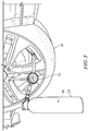
FIG. 4 is a perspective view of the tire and the second pressurized container fromFIG. 1 without an in-line pressure gauge wherein the contents of the second pressurized container are being transferred to the tire; and -
FIG. 5 is a perspective view similar toFIG. 4 wherein the second pressurized container includes the in-line pressure gauge; - Other aspects and advantages of the present invention will become apparent upon consideration of the following detailed description, wherein similar structures have like or similar reference numerals.
- The present invention is directed to tire repair systems and methods of using tire repair systems to seal a tire. While systems and methods of the present invention may be embodied in many different forms, several specific embodiments are discussed herein with the understanding that the present invention is to be considered only as an exemplification of the principles of the invention, and it is not intended to limit the invention to the embodiments described.
- Referring to
FIG. 1 , atire repair system 20 is depicted as including a first pressurizedcontainer 22 and a second pressurizedcontainer 24. As suggested byFIG. 2 , atire 10 in need of repair may include at least one puncture orhole 12. A tire repair method includes transferring afirst fluid 32 from within the first pressurizedcontainer 22 into atire 10, followed by transferring asecond fluid 34 from within the second pressurizedcontainer 24 into thetire 10. Thefirst fluid 32 includes the first propellant and a sealant composition. The sealant composition in this example includes the emulsion of styrene butadiene rubber (SBR) in water. - The
second fluid 34 includes the second propellant and isopropyl alcohol, also called isopropanol (IPA). After thesecond fluid 34 is transferred into thetire 10, SBR and IPA alcohol interact to form a rubber agglomerate. The agglomerated rubber acts to seal one or more holes in the tire to repair it. Greater detail and examples of the tire repair method will be discussed in greater detail hereinbelow. - The
first container 22 may be an aerosol can that includes thefirst fluid 32. Thefirst fluid 32 includes the first propellant and the sealant composition. Thefirst fluid 32 may comprise from about 5 weight percentage (wt%) to about 25 wt% of the first propellant. Preferably, thefirst fluid 32 may comprise from about 5 wt% to about 10 wt% of the first propellant. Most preferably, thefirst fluid 32 comprises about 6 wt% of the first propellant. Thefirst fluid 32 may comprise from about 75 wt% to about 99 wt% of the sealant composition. Preferably, thefirst fluid 32 comprises from about 85 wt% to about 95 wt% of the sealant composition. Most preferably, thefirst fluid 32 comprises about 94 wt% of the sealant composition. Thefirst fluid 32 comprises about 6 wt% of the first propellant and about 94 wt% of the sealant composition. - Aerosol type propellants are contemplated in accordance with the present invention. Representative propellants that may be used include but are not limited to propane, butane, isobutane and trans-1,3,3,3-Tetrafluoro-1-propene; and combinations thereof. Preferably the first propellant includes a flammable propellant such as butane, isobutane, and propane or more preferably trans-1,3,3,3-Tetrafluoro-1-propene, also called HFO1234ze. HFO1234ze is advantageously non-flammable by ASTME-681 and EU A11 test methods. These propellants are preferred as they provide a low vapour pressure and serve to dispense the first fluid from the first container into a tire but without sufficient force, or volume (at the stated levels) for the fluid to be significantly expelled through a leak before application of the second fluid to occasion the conversion of the first fluid to a form which enables sealing.
- More preferably the first propellant comprises, consists essentially of or consists of butane and isobutane. Most preferably the first propellant comprises about 46 wt% of n-butane, about 23 wt% of isobutane, and about 1 wt% of propane. Preferably the
first fluid 32 includes sufficient propellant to disperse the SBR throughout atire 10 but without expelling significant fluid. In particular a weight ratio of SBR in the emulsion to butane propellant is may be 6:1 to 8:1, preferably 15:2. SBR to total propellant ratio may be 4:1 to 6:1, preferably 5:1 with a preferred propellant composition, such as 46 wt% of n-butane, 23 wt% of isobutane, and 1 wt% of propane (each +/- 2%). In other embodiments, thefirst fluid 32 may not include sufficient propellant to fully inflate thetire 10. - The sealant composition may comprise, or consist essentially of, or consist of an emulsion of SBR in water with at least one foaming agent. The sealant composition includes an aqueous dispersion of SBR. The aqueous dispersion of SBR may comprise from 60 to 75% SBR, most preferably about 67 wt% SBR. In the following, the given weight percentages of SBR exclude the weight of water. The sealant composition may comprise from about 13 wt% to about 40 wt% of SBR. Preferably, the sealant composition comprises from about 26 wt% to about 34 wt% of SBR. Most preferably, the sealant composition comprises about 31 wt% of SBR. The sealant composition may comprise from about 26 wt% to about 80 wt% of water (including the water that is part of the aqueous dispersion of SBR). Preferably, the sealant composition comprises from about 38 wt% to about 52 wt% of water. More preferably, the sealant composition comprises about 31 wt% of SBR to about 47 wt% of water. Most preferably, the sealant composition comprises about 47 wt% of water.
- When the
first fluid 32 is transferred into thetire 10, a foam including the emulsion of SBR fills at least a portion of the tire. The presence of the at least one foaming agent enables the creation of the foam made of the emulsion of SBR with the first propellant acting as a blowing agent and a plurality of cells formed in the foam that are inflated by the first propellant acting as a blowing agent. Examples of foaming agents may include potassium oleate, ammonium lauryl sulfate, other suitable surfactants, and/or any other suitable foaming agent(s). - The sealant composition may include potassium oleate and/or ammonium lauryl sulfate as a foaming agent or agents. Other foaming agents, alone or in combination with any of the noted foaming agents, may additionally or alternatively be used. The sealant composition comprises from about 1 wt% to about 15 wt% of one or more foaming agents. Preferably, the sealant composition comprises from about 2 wt% to about 5.5 wt% of one or more foaming agents. Most preferably, the sealant composition comprises about 4 wt% of one or more foaming agents.
- The sealant composition may comprise from about 1 wt% to about 10 wt% of potassium oleate. Preferably, the sealant composition comprises from about 2 wt% to about 4 wt% of potassium oleate. Most preferably, the sealant composition comprises about 3 wt% of potassium oleate. The sealant composition may include from about 0.1 wt% to about 5 wt% of ammonium lauryl sulfate. Preferably, the sealant composition includes from about 0.5 wt% to about 1.5 wt% of ammonium lauryl sulfate. Most preferably, the sealant composition comprises about 0.8 wt% of ammonium lauryl sulfate.
- The sealant composition may include from about 1 wt% to about 10 wt% of potassium oleate and from about 0.1 wt% to about 5 wt% of ammonium lauryl sulfate. Preferably, the sealant composition includes from about 2 wt% to about 4 wt% of potassium oleate and from about 0.5 wt% to about 1.5 wt% of ammonium lauryl sulfate. Most preferably, the sealant composition includes about 3 wt% of potassium oleate and about 0.8 wt% of ammonium lauryl sulfate.
- The sealant composition may optionally include an antioxidant. The inclusion of an antioxidant prevents discoloration and oxidation. In an illustrative embodiment, the sealant composition includes butylated hydroxyanisole (BHA) as an antioxidant. Alternatively or additionally, any other suitable antioxidant(s) may be used. The sealant composition may comprise from about 0.01 wt% to about 5 wt% of one or more antioxidants, for example, BHA. More preferably, the sealant composition includes from about 0.01 wt% to about 2 wt% of one or more antioxidants. Still more preferably, the sealant composition includes from about 0.01 wt% to about 0.5 wt% of one or more antioxidants, for example, BHA Most preferably, the sealant composition comprises about 0.1 wt% of BHA.
- The sealant composition may also optionally include a freezing point depressant. The presence of a freezing point depressant prevents the first fluid 32 from freezing in low temperatures. If the first fluid froze, water in the SBR emulsion might expand and rupture or otherwise damage the first
fluid container 22. Further, the presence of a freezing point depressant prevents any valves from freezing during the transfer process. An example of a freezing point depressant is monopropylene glycol (MPG). One or more of MPG or any other suitable freezing point depressants may be utilized. The sealant composition may include from about 10 wt% to about 50 wt% of MPG. Preferably, the sealing composition includes from about 15 wt% to about 20 wt% of MPG. Most preferably, the sealant composition includes about 18 wt% of MPG. - The sealant composition may consist essentially of an emulsion of SBR in water and at least one foaming agent. In other embodiments, the sealant composition may consist essentially of an emulsion of SBR in water, at least one foaming agent, and an antioxidant. In some other embodiments, the sealant composition may consist essentially of an emulsion of SBR in water, at least one foaming agent, an antioxidant, and a freezing point depressant.
- The
second container 24 may be an aerosol can that includes thesecond fluid 34. Thesecond fluid 34 includes the second propellant and IPA. Thesecond fluid 34 may include from about 60 wt% to about 99 wt% of the second propellant. Preferably, thesecond fluid 34 may include from about 60 wt% to about 90 wt% of the second propellant. More preferably, thesecond fluid 34 may include from about 85 wt% to about 90 wt% of the second propellant. Most preferably, thesecond fluid 34 may include about 86.3 wt% of the second propellant. The second propellant is preferably a high vapour pressure liquid or a gas, preferably with an air component; carbon dioxide, nitrogen, argon or mixtures thereof. - The combination of a first butane based propellant and a second air derived propellant addresses several issues. First, the use of small quantities, such as as low as 6% based hydrocarbon, facilitates homogeneous admixture of the propellant with SBR based sealant. This enables a liquid to be dispensed to a tire which itself comprises enough propellant to cause foaming when expanding inside a deflated tire. Too much propellant blows sealant out of large puncture apertures (and is hence a reason why current products can be inadequate for large aperture punctures) and too little cannot drive sealant into a tire from a (first) fluid container. However, such an optimized first fluid cannot effectively inflate a tire nor will it break the SBR emulsion (or if it does foaming and even tire filling will not occur). Hence, further inflation with air alone is unsatisfactory. A second fluid is therefore required, butane and similar propellants can be ineffective at sub-zero temperatures for tire inflation. Hence, a second fluid comprising an air derived propellant with isopropanol gives both pressure and volume of gas for tire inflation whilst breaking the SBR emulsion to deposit the by then evenly distributed SBR derived from the foam on internal tire surfaces. This enables punctures of up to 6mm diameter to be sealed, which has hitherto not been possible with single canister aerosol tire inflators.
- The
second fluid 34 may comprise from about 1 wt% to about 25 wt% of IPA. Preferably, thesecond fluid 34 may comprise from about 10 wt% to about 15 wt% of IPA. More preferably, thesecond fluid 34 may comprise about 13.6 wt% of IPA. Most preferably, thesecond fluid 34 may comprise about 86.3 wt% of the second propellant and about 13.6 wt% of IPA. - The second propellant, whilst preferably being air derived (as above), may alternatively, or in addition, include one or more of propane, butane, isobutane and trans-1,3,3,3-Tetrafluoro-1-propene. The second propellant may comprise butane, isobutane, and propane. The second propellant may comprise trans-1,3,3,3-Tetrafluoro-1-propene, also called HFO1234ze. HFO1234ze is advantageously non-flammable by ASTM E-681 and EU A11 test methods. The second propellant may include butane and isobutane. The second propellant may include about 46 wt% of butane, about 23 wt% of isobutane, and about 1 wt% of propane. In other embodiments, the
second container 24 includes sufficient propellant to inflate thetire 10. - The
second fluid 34 includes IPA to cause an agglomeration reaction when IPA breaks the SBR emulsion. As the SBR emulsion breaks, agglomerated particles form that can cover and/or fill a hole or puncture in thetire 10. Eventually, sufficient agglomerated particles bind together and seal the hole or puncture in thetire 10. - When the
first fluid 32 is transferred into thetire 10, as suggested byFIG. 3 , a foam including the emulsion of SBR fills at least a portion of thetire 10. When thefirst fluid 32 leaves the firstpressurized container 22 into the larger volume of thetire 10, the first propellant is no longer dissolved into the sealant composition. The first propellant acts as a blowing agent, and the foaming agent(s) in the sealant composition reduce surface tension and enable the SBR emulsion to form bubbles or cells that are inflated by the first propellant. The walls of these bubbles or cells include the SBR emulsion. The foam forms and fills at least a portion of thetire 10, causing SBR to be distributed throughout the interior of thetire 10. - When the
second fluid 34 is transferred into thetire 10, as suggested byFIG. 4 , the IPA, under high pressure from the second propellant, spreads throughout thetire 10 and intimately mixes with the SBR emulsion. The SBR emulsion breaks and agglomerated rubber particles form throughout the interior of thetire 10. The agglomerated rubber particles, bond together and to the walls of thetire 10, spread over the at least one hole or puncture 12 to seal thetire 10. As suggested byFIGS. 4 and5 , the second propellant pressurizes thetire 10 to a first pressure and fully inflates thetire 10. After a period of time, the interior of thetire 10 cools and the pressure inside thetire 10 lowers to a second pressure that is still sufficient to maintain inflation of thetire 10. - In an illustrative embodiment, a vehicle with the repaired
tire 10 may be driven before the interior of thetire 10 cools. In other embodiments, a vehicle with thetire 10 may be driven after the interior of thetire 10 cools. - The first
pressurized container 22 may have a variety of sizes. The volume of thetarget tire 10 may be considered to determine the minimum necessary size of the first pressurized container. The firstpressurized container 22 may contain a volume of first fluid 32 from about 300mL to about 600mL. The firstpressurized container 22 may contain a volume offirst fluid 32 of about 300mL, about 350mL, about 400mL, about 450mL, about 500mL, about 550mL, or about 600mL. - The second
pressurized container 24 may have a size determined by the volume of a target tire and the preferred pressure may be considered to determine the proper size of the second pressurized container. The secondpressurized container 24 may contain a volume of first fluid 32 from about 300mL to about 600mL. In some embodiments, the secondpressurized container 24 may contain a volume ofsecond fluid 34 of about 300mL, about 350mL, about 400mL, about 450mL, about 500mL, about 550mL, or about 600mL. - In illustrative embodiments, the second
pressurized container 24 may include an in-line pressure gauge 26, as suggested byFIG. 5 . In such illustrative embodiments, the secondpressurized container 24 may include thesecond fluid 34 and further comprise a delivery device attached to the second pressurized container for delivering the second fluid 34 from the container to thetire 10 to be repaired. The delivery device may comprise (1) an actuator for actuating a valve of the second pressurized container and for permitting, when actuated, the second fluid to be delivered from the container by means of a fluid flow path in fluid communication with the valve and (2) a pressure gauge in communication with the fluid flow path to measure a pressure within the fluid flow path. In embodiments with the in-line pressure gauge 26, the secondpressurized container 24 may be larger than necessary to inflate thetire 10 to a desired pressure. A user may elect to transfer the contents of the second pressurized container into thetire 10 while watching thepressure gauge 26. When the pressure in thetire 10 reaches a target range, the user may elect to stop transferring the contents of the second pressurized container. In this manner, a large container, for example a container having a volume of 600ml and which would be capable of filling most tires, can be utilized. The in-line pressure gauge 26 may eliminate the need for various different sizes of containers for differently sized tires. - In illustrative embodiments, the user may elect to stop transferring the contents of the second
pressurized container 24 when the pressure in thetire 10 is from about 18 to about 50 psi (about 1,24 to about 3,45 bar). In other embodiments, the user may elect to stop transferring the contents of the secondpressurized container 24 when the pressure in thetire 10 is from about 20 to about 40 psi (about 1,38 to about 2,76 bar). In some embodiments, the user may elect to stop transferring the contents of the secondpressurized container 24 when the pressure in thetire 10 is from about 35 to about 40 psi (about 2,41 to about 2,76 bar). - Specific, non-limiting examples of the first and second fluids and the components thereof are included below:
Table 1 - First Fluid First Fluid wt%/wt First Propellant 5.789% Sealant Composition 94.211% Table 2 - First Propellant First Propellant wt%/wt Butane 46% Isobutane 23% Propane 1% Table 3 - Second Fluid Second Fluid wt%/wt Second Propellant 86.361% Isopropyl Alcohol 13.639% Table 4 Second Propellant wt%/wt Butane 46% Isobutane 23% Propane 1% - Tables 1 to 4 in combination provide a preferred composition for use in a kit, method and containers of the present invention.
Table 5 - A Preferred Sealant Composition Sealant Composition wt%/wt Litex S61 (RTM) - Aqueous dispersion of a copolymer of styrene and 1,3-butadiene. (Concentration ca. 67 %) SBR dissolved in water 47% Water Water 31.088% Potassium Oleate Premix Potassium Oleate - foaming agent 3% Texapon ALS IS(RTM) Ammonium Lauryl Sulfate - foaming agent 0.812 % Antrancine 12 BHA (RTM) BHA - antioxidant 0.1% Monopropylene Glycol MPG - freezing depressant 18% Totals Total SBR 31.333% Total Water 46.755% Total Foaming Agents 3.812% Total Antioxidant 0.1% Total Freezing Depressants 18% - For each trial below in Table 6, a P205/55/R16 tire had a 6mm diameter hole drilled in between a middle of a tread pattern of the tire. The tire was fitted to a car and the hole was located on the upper half of the wheel circumference, between 9 and 3 o'clock as if on a clock face. A first pressurized container having a volume of 500mL containing the first fluid from Table 1 was dispensed for approximately two minutes into the tire. Immediately afterwards, a second pressurized container having a volume of 500mL containing the second fluid from Table 3 was dispensed for approximately two minutes into the tire. The car was driven immediately and stopped after 6 miles (10 km) to check the pressure. The car was driven a further 6 miles (10 km) for a total of twelve miles (20 km) and the pressure was checked again. The car was left overnight at ambient temperature with the location of the drilled hole in the tire facing directly upwards.
Table 6 Trial Pressure at 6 miles (10 km) Pressure at 12 miles (20 km) Pressure at 24 hours at ambient temperature psig kPag psig kPag psig kPag 1 39 269 40.5 279.2 * * 2 38 262 39 269 13.5 93.1 3 36 248 38 262 * * 4 39 269 40 276 * * 5 44 303 46 317 19 131 6 40 276 42 290 23 159 7 26 179 29 200 13 90 8 39 269 40.5 279.2 21.5 148.2 9 40 276 41.5 286.1 27 186 10 34 234 37.5 258.6 21.5 148.2 Avg. 37.5 258.6 39.4 271.7 19.79 136.4 * Data not available. - As seen in Table 6, after 6 miles (10 km) of driving, the hot gases inside the tire are at an average pressure of 37.5 psig (258.6 kPag). After 12 miles (20 km) of driving, the pressure increased further to an average of 39.4 psig (271.7 kPag). After 24 hours of cooling, where data was available, the tire maintained an average pressure of 19.79 psig (136.4 kPag). The tire maintained an acceptable pressure for driving even after cooling, enabling a car with a repaired tire to be able to seek a repair shop.
- The experiment above was repeated with a Continental ContiMobility, a product currently on the market. For each trial below in Table 7, a P205/55/R16 tire had a 3mm to 6mm diameter hole drilled in between a middle of a tread pattern of the tire. The tire was fitted to a car and the hole was located on the upper half of the wheel circumference, between 9 and 3 o'clock as if on a clock face. The manufacturer's instructions for the Continental ContiMobility kit (450mL) were followed. The 450mL ContiMobility repair and inflation product was transferred into the tire and the pressure was measured. The car was driven immediately (to the extent possible) and stopped after 6 miles (10 km) to check the pressure. The car was driven (to the extent possible) a further 6 miles (10 km) for a total of twelve miles (20 km) and the pressure was checked again.
Table 7 Trial Product Dispense Time Puncture Type Pressure After Inflation Pressure at 6 miles (10 km) Pressure at 12 miles (20 km) psig kPag psig kPag psig kPag 1 ContiKit 450 mL ∼10 min Drill 3mm 28 193.1 25.5 175.8 24 165.5 2 ContiKit 450 mL ∼10 min Drill 4mm 26 179.3 19 131 19 131 3 ContiKit 450 mL ∼10 min Drill 5mm Fail Fail Fail 4 ContiKit 450 mL ∼10 min Drill 6mm Fail Fail Fail - The Continental ContiMobility Kit failed to establish a seal for a 5mm drilled hole and for a 6mm drilled hole. Further, for the 4mm drilled hole, slight bubbling after 12 miles (19,3 km) indicated a very slow leak. The data in Table 6 for the preferred embodiment of the disclosed invention indicate a superior performance for larger punctures than the existing Continental ContiMobility Kit.
Claims (12)
- A kit (20) for repairing a tire (10), comprising,a first pressurized container (22) including a first fluid (32), the first fluid comprising a first propellant, a styrene butadiene rubber emulsion and a foaming agent; anda second pressurized container (24) including a second fluid (34), the second fluid comprising a second propellant and isopropyl alcohol.
- The kit of claim 1, wherein the first propellant included in the first pressurized container (22) is for dispersing a foam containing the styrene butadiene rubber throughout the interior of the tire (10).
- The kit of claim 1 or claim 2, wherein the second propellant included in the second pressurized container (24) is for inflating the tire (10).
- The kit of claim 1, wherein the first fluid (32) comprises:from 26 wt% to 34 wt% of styrene butadiene rubber,from 38 wt% to 52 wt% of water andfrom 2 wt% to 5.5 wt% of one or more foaming agents.
- The kit of claim 4, wherein the first fluid (32) comprises:from 1 wt% to 10 wt% of potassium oleate andfrom 0.1 wt% to 5 wt% of ammonium lauryl sulfate.
- The kit of claim 5, wherein the first fluid (32) comprises:
from 0.01 wt% to 5 wt% of butylated hydroxyanisole. - The kit of claim 5 or claim 6, wherein the first fluid (32) comprises:
from 10 wt% to 50 wt% of monopropylene glycol. - The kit of any one of the preceding claims, wherein the second fluid (34) comprises:
from 5 wt% to 25 wt% of isopropyl alcohol. - The kit of claim 8, wherein the second fluid (34) comprises:
from 60 wt% to 99 wt% of the second propellant. - A method for sealing a tire (10) with a hole, comprising,providing a kit (20) as provided in any of claims 1 to 9transferring a first fluid (32) into the tire, the first fluid comprising a first propellant and an emulsion including styrene butadiene rubber and a foaming agent;transferring a second fluid (34) into the tire after transferring the first fluid into the tire, the second fluid comprising a second propellant and isopropyl alcohol; andwherein an interaction between the styrene butadiene rubber in the first fluid and the isopropyl alcohol in the second fluid results in a plurality of rubber particles that agglomerate and seal the hole in the tire.
- The method of claim 10, wherein the first fluid (32) comprises:from 26 wt% to 34 wt% styrene butadiene rubber,from 38 wt% to 52 wt% water andfrom 2 wt% to 5.5 wt% of one or more foaming agents.
- The method of claim 11, wherein the second fluid (34) comprises:from 5 wt% to 25 wt% of isopropyl alcohol andfrom 60 wt% to 90 wt% of the second propellant.
Applications Claiming Priority (2)
| Application Number | Priority Date | Filing Date | Title |
|---|---|---|---|
| GB1511468.9A GB2534951B (en) | 2015-06-30 | 2015-06-30 | Tire sealer system and method |
| PCT/GB2016/051957 WO2017001849A1 (en) | 2015-06-30 | 2016-06-30 | Tire sealer system and method |
Publications (2)
| Publication Number | Publication Date |
|---|---|
| EP3317086A1 EP3317086A1 (en) | 2018-05-09 |
| EP3317086B1 true EP3317086B1 (en) | 2019-08-07 |
Family
ID=53872450
Family Applications (1)
| Application Number | Title | Priority Date | Filing Date |
|---|---|---|---|
| EP16736574.1A Active EP3317086B1 (en) | 2015-06-30 | 2016-06-30 | Tire sealer system and method |
Country Status (7)
| Country | Link |
|---|---|
| US (1) | US10576703B2 (en) |
| EP (1) | EP3317086B1 (en) |
| JP (1) | JP6835754B2 (en) |
| CN (1) | CN107735245B (en) |
| ES (1) | ES2754438T3 (en) |
| GB (1) | GB2534951B (en) |
| WO (1) | WO2017001849A1 (en) |
Family Cites Families (12)
| Publication number | Priority date | Publication date | Assignee | Title |
|---|---|---|---|---|
| US4501825A (en) * | 1984-06-28 | 1985-02-26 | Pennzoil Company | Tire sealer and inflator |
| FR2753653B1 (en) * | 1996-09-24 | 1998-11-13 | DEVICE FOR QUICK REPAIR AFTER PITCHING HEAVY-DUTY TIRES | |
| PE20010605A1 (en) * | 1999-07-14 | 2001-06-29 | Pennzoil Quaker State Co | COMPOSITION, METHOD AND DEVICE FOR SEALING AND INFLATING RUBBER |
| CN1960850B (en) * | 2004-05-27 | 2010-12-08 | 株式会社普利司通 | Sealed pumping device |
| JP2008049598A (en) * | 2006-08-25 | 2008-03-06 | Bridgestone Corp | Sealant injection device |
| DE202007009152U1 (en) * | 2007-06-29 | 2007-12-13 | Premium Vertriebs Gmbh | Device for sealing tires |
| JP2010001394A (en) * | 2008-06-20 | 2010-01-07 | Bridgestone Corp | Puncture sealing agent |
| JP2010137469A (en) * | 2008-12-12 | 2010-06-24 | Toyota Motor Corp | Flat tire repairing apparatus |
| US20110257282A1 (en) * | 2010-04-19 | 2011-10-20 | Honeywell International, Inc. | Tire sealer and inflater composition |
| DE112011101805B4 (en) * | 2010-05-27 | 2014-08-28 | The Yokohama Rubber Co., Ltd. | Liquid coagulant |
| DE112014001581B4 (en) * | 2013-03-22 | 2017-02-23 | The Yokohama Rubber Co., Ltd | Use of an emulsion coagulant and this benefit of the puncture repair kit |
| CN103497731B (en) | 2013-10-18 | 2015-08-19 | 庄汉明 | A kind of self-mending agent for tyre puncture and preparation method thereof |
-
2015
- 2015-06-30 GB GB1511468.9A patent/GB2534951B/en active Active
-
2016
- 2016-06-30 CN CN201680038162.1A patent/CN107735245B/en active Active
- 2016-06-30 JP JP2017568400A patent/JP6835754B2/en active Active
- 2016-06-30 US US15/580,220 patent/US10576703B2/en active Active
- 2016-06-30 ES ES16736574T patent/ES2754438T3/en active Active
- 2016-06-30 EP EP16736574.1A patent/EP3317086B1/en active Active
- 2016-06-30 WO PCT/GB2016/051957 patent/WO2017001849A1/en not_active Ceased
Non-Patent Citations (1)
| Title |
|---|
| None * |
Also Published As
| Publication number | Publication date |
|---|---|
| JP6835754B2 (en) | 2021-02-24 |
| GB2534951B (en) | 2017-06-21 |
| CN107735245A (en) | 2018-02-23 |
| GB2534951A (en) | 2016-08-10 |
| JP2018527215A (en) | 2018-09-20 |
| US10576703B2 (en) | 2020-03-03 |
| US20180162079A1 (en) | 2018-06-14 |
| EP3317086A1 (en) | 2018-05-09 |
| CN107735245B (en) | 2020-07-28 |
| GB201511468D0 (en) | 2015-08-12 |
| WO2017001849A1 (en) | 2017-01-05 |
| ES2754438T3 (en) | 2020-04-17 |
Similar Documents
| Publication | Publication Date | Title |
|---|---|---|
| US6345650B1 (en) | Tire repair device and method | |
| JP4540609B2 (en) | Puncture sealant | |
| JPH09118779A (en) | Punk sealant and tire sealing / pump up device | |
| CN102971392B (en) | Tire sealant and aeration agent composition | |
| EP1215058A2 (en) | Method and apparatus for inflating objects | |
| CN100379834C (en) | tire sealant | |
| EP1200246A1 (en) | Tire sealing and inflating composition and method of use | |
| JP6945919B2 (en) | Sealant for tire repair | |
| US10576703B2 (en) | Tire sealer system and method | |
| JP2006111726A (en) | Puncture sealer | |
| US20160312081A1 (en) | Enviromentally friendly aerosolized latex tire sealant | |
| JP4553712B2 (en) | Puncture tire repair method and puncture tire repair sealant | |
| US9862156B2 (en) | Environmentally friendly aerosolized latex tire sealant | |
| CA2983584C (en) | Environmentally friendly aerosolized latex tire sealant | |
| EP4628290A1 (en) | Sealant bottle and method for repairing tire | |
| JP2010001394A (en) | Puncture sealing agent | |
| JP2013249447A (en) | Puncture sealant and method of producing the same | |
| JP2010100754A (en) | Puncture-sealing agent | |
| JP4754900B2 (en) | Puncture sealant | |
| WO2018008722A1 (en) | Puncture sealant | |
| JP2012172127A (en) | Puncture sealing agent and method for producing the same | |
| US20070095420A1 (en) | Perfluorocarbon gas insufflation | |
| JP2010260904A (en) | Puncture sealing agent | |
| JP2020531324A (en) | How to seal and air fill inflatable articles | |
| JP2010100753A (en) | Puncture-sealing agent and method for manufacturing the same |
Legal Events
| Date | Code | Title | Description |
|---|---|---|---|
| STAA | Information on the status of an ep patent application or granted ep patent |
Free format text: STATUS: THE INTERNATIONAL PUBLICATION HAS BEEN MADE |
|
| PUAI | Public reference made under article 153(3) epc to a published international application that has entered the european phase |
Free format text: ORIGINAL CODE: 0009012 |
|
| STAA | Information on the status of an ep patent application or granted ep patent |
Free format text: STATUS: REQUEST FOR EXAMINATION WAS MADE |
|
| 17P | Request for examination filed |
Effective date: 20180117 |
|
| AK | Designated contracting states |
Kind code of ref document: A1 Designated state(s): AL AT BE BG CH CY CZ DE DK EE ES FI FR GB GR HR HU IE IS IT LI LT LU LV MC MK MT NL NO PL PT RO RS SE SI SK SM TR |
|
| AX | Request for extension of the european patent |
Extension state: BA ME |
|
| DAV | Request for validation of the european patent (deleted) | ||
| DAX | Request for extension of the european patent (deleted) | ||
| RIN1 | Information on inventor provided before grant (corrected) |
Inventor name: HITCHMAN, RICHARD Inventor name: ELLIS, BRUCE |
|
| GRAP | Despatch of communication of intention to grant a patent |
Free format text: ORIGINAL CODE: EPIDOSNIGR1 |
|
| STAA | Information on the status of an ep patent application or granted ep patent |
Free format text: STATUS: GRANT OF PATENT IS INTENDED |
|
| RIC1 | Information provided on ipc code assigned before grant |
Ipc: B29L 30/00 20060101ALN20190207BHEP Ipc: B29C 73/16 20060101AFI20190207BHEP |
|
| RIC1 | Information provided on ipc code assigned before grant |
Ipc: B29L 30/00 20060101ALN20190211BHEP Ipc: B29C 73/16 20060101AFI20190211BHEP |
|
| INTG | Intention to grant announced |
Effective date: 20190301 |
|
| RBV | Designated contracting states (corrected) |
Designated state(s): AL AT BE BG CH CY CZ DE DK EE ES FI FR GR HR HU IE IS IT LI LT LU LV MC MK MT NL NO PL PT RO RS SE SI SK SM TR |
|
| GRAS | Grant fee paid |
Free format text: ORIGINAL CODE: EPIDOSNIGR3 |
|
| GRAA | (expected) grant |
Free format text: ORIGINAL CODE: 0009210 |
|
| STAA | Information on the status of an ep patent application or granted ep patent |
Free format text: STATUS: THE PATENT HAS BEEN GRANTED |
|
| AK | Designated contracting states |
Kind code of ref document: B1 Designated state(s): AL AT BE BG CH CY CZ DE DK EE ES FI FR GR HR HU IE IS IT LI LT LU LV MC MK MT NL NO PL PT RO RS SE SI SK SM TR |
|
| REG | Reference to a national code |
Ref country code: CH Ref legal event code: EP Ref country code: AT Ref legal event code: REF Ref document number: 1163172 Country of ref document: AT Kind code of ref document: T Effective date: 20190815 |
|
| REG | Reference to a national code |
Ref country code: IE Ref legal event code: FG4D |
|
| REG | Reference to a national code |
Ref country code: DE Ref legal event code: R096 Ref document number: 602016018193 Country of ref document: DE |
|
| REG | Reference to a national code |
Ref country code: NL Ref legal event code: FP |
|
| REG | Reference to a national code |
Ref country code: LT Ref legal event code: MG4D |
|
| PG25 | Lapsed in a contracting state [announced via postgrant information from national office to epo] |
Ref country code: FI Free format text: LAPSE BECAUSE OF FAILURE TO SUBMIT A TRANSLATION OF THE DESCRIPTION OR TO PAY THE FEE WITHIN THE PRESCRIBED TIME-LIMIT Effective date: 20190807 Ref country code: SE Free format text: LAPSE BECAUSE OF FAILURE TO SUBMIT A TRANSLATION OF THE DESCRIPTION OR TO PAY THE FEE WITHIN THE PRESCRIBED TIME-LIMIT Effective date: 20190807 Ref country code: NO Free format text: LAPSE BECAUSE OF FAILURE TO SUBMIT A TRANSLATION OF THE DESCRIPTION OR TO PAY THE FEE WITHIN THE PRESCRIBED TIME-LIMIT Effective date: 20191107 Ref country code: PT Free format text: LAPSE BECAUSE OF FAILURE TO SUBMIT A TRANSLATION OF THE DESCRIPTION OR TO PAY THE FEE WITHIN THE PRESCRIBED TIME-LIMIT Effective date: 20191209 Ref country code: HR Free format text: LAPSE BECAUSE OF FAILURE TO SUBMIT A TRANSLATION OF THE DESCRIPTION OR TO PAY THE FEE WITHIN THE PRESCRIBED TIME-LIMIT Effective date: 20190807 Ref country code: BG Free format text: LAPSE BECAUSE OF FAILURE TO SUBMIT A TRANSLATION OF THE DESCRIPTION OR TO PAY THE FEE WITHIN THE PRESCRIBED TIME-LIMIT Effective date: 20191107 Ref country code: LT Free format text: LAPSE BECAUSE OF FAILURE TO SUBMIT A TRANSLATION OF THE DESCRIPTION OR TO PAY THE FEE WITHIN THE PRESCRIBED TIME-LIMIT Effective date: 20190807 |
|
| REG | Reference to a national code |
Ref country code: AT Ref legal event code: MK05 Ref document number: 1163172 Country of ref document: AT Kind code of ref document: T Effective date: 20190807 |
|
| PG25 | Lapsed in a contracting state [announced via postgrant information from national office to epo] |
Ref country code: RS Free format text: LAPSE BECAUSE OF FAILURE TO SUBMIT A TRANSLATION OF THE DESCRIPTION OR TO PAY THE FEE WITHIN THE PRESCRIBED TIME-LIMIT Effective date: 20190807 Ref country code: LV Free format text: LAPSE BECAUSE OF FAILURE TO SUBMIT A TRANSLATION OF THE DESCRIPTION OR TO PAY THE FEE WITHIN THE PRESCRIBED TIME-LIMIT Effective date: 20190807 Ref country code: AL Free format text: LAPSE BECAUSE OF FAILURE TO SUBMIT A TRANSLATION OF THE DESCRIPTION OR TO PAY THE FEE WITHIN THE PRESCRIBED TIME-LIMIT Effective date: 20190807 Ref country code: GR Free format text: LAPSE BECAUSE OF FAILURE TO SUBMIT A TRANSLATION OF THE DESCRIPTION OR TO PAY THE FEE WITHIN THE PRESCRIBED TIME-LIMIT Effective date: 20191108 Ref country code: IS Free format text: LAPSE BECAUSE OF FAILURE TO SUBMIT A TRANSLATION OF THE DESCRIPTION OR TO PAY THE FEE WITHIN THE PRESCRIBED TIME-LIMIT Effective date: 20191207 |
|
| PG25 | Lapsed in a contracting state [announced via postgrant information from national office to epo] |
Ref country code: TR Free format text: LAPSE BECAUSE OF FAILURE TO SUBMIT A TRANSLATION OF THE DESCRIPTION OR TO PAY THE FEE WITHIN THE PRESCRIBED TIME-LIMIT Effective date: 20190807 |
|
| REG | Reference to a national code |
Ref country code: ES Ref legal event code: FG2A Ref document number: 2754438 Country of ref document: ES Kind code of ref document: T3 Effective date: 20200417 |
|
| PG25 | Lapsed in a contracting state [announced via postgrant information from national office to epo] |
Ref country code: EE Free format text: LAPSE BECAUSE OF FAILURE TO SUBMIT A TRANSLATION OF THE DESCRIPTION OR TO PAY THE FEE WITHIN THE PRESCRIBED TIME-LIMIT Effective date: 20190807 Ref country code: PL Free format text: LAPSE BECAUSE OF FAILURE TO SUBMIT A TRANSLATION OF THE DESCRIPTION OR TO PAY THE FEE WITHIN THE PRESCRIBED TIME-LIMIT Effective date: 20190807 Ref country code: RO Free format text: LAPSE BECAUSE OF FAILURE TO SUBMIT A TRANSLATION OF THE DESCRIPTION OR TO PAY THE FEE WITHIN THE PRESCRIBED TIME-LIMIT Effective date: 20190807 Ref country code: DK Free format text: LAPSE BECAUSE OF FAILURE TO SUBMIT A TRANSLATION OF THE DESCRIPTION OR TO PAY THE FEE WITHIN THE PRESCRIBED TIME-LIMIT Effective date: 20190807 Ref country code: AT Free format text: LAPSE BECAUSE OF FAILURE TO SUBMIT A TRANSLATION OF THE DESCRIPTION OR TO PAY THE FEE WITHIN THE PRESCRIBED TIME-LIMIT Effective date: 20190807 |
|
| PG25 | Lapsed in a contracting state [announced via postgrant information from national office to epo] |
Ref country code: CZ Free format text: LAPSE BECAUSE OF FAILURE TO SUBMIT A TRANSLATION OF THE DESCRIPTION OR TO PAY THE FEE WITHIN THE PRESCRIBED TIME-LIMIT Effective date: 20190807 Ref country code: SM Free format text: LAPSE BECAUSE OF FAILURE TO SUBMIT A TRANSLATION OF THE DESCRIPTION OR TO PAY THE FEE WITHIN THE PRESCRIBED TIME-LIMIT Effective date: 20190807 Ref country code: IS Free format text: LAPSE BECAUSE OF FAILURE TO SUBMIT A TRANSLATION OF THE DESCRIPTION OR TO PAY THE FEE WITHIN THE PRESCRIBED TIME-LIMIT Effective date: 20200224 Ref country code: SK Free format text: LAPSE BECAUSE OF FAILURE TO SUBMIT A TRANSLATION OF THE DESCRIPTION OR TO PAY THE FEE WITHIN THE PRESCRIBED TIME-LIMIT Effective date: 20190807 |
|
| REG | Reference to a national code |
Ref country code: DE Ref legal event code: R097 Ref document number: 602016018193 Country of ref document: DE |
|
| PLBE | No opposition filed within time limit |
Free format text: ORIGINAL CODE: 0009261 |
|
| STAA | Information on the status of an ep patent application or granted ep patent |
Free format text: STATUS: NO OPPOSITION FILED WITHIN TIME LIMIT |
|
| PG2D | Information on lapse in contracting state deleted |
Ref country code: IS |
|
| 26N | No opposition filed |
Effective date: 20200603 |
|
| PG25 | Lapsed in a contracting state [announced via postgrant information from national office to epo] |
Ref country code: SI Free format text: LAPSE BECAUSE OF FAILURE TO SUBMIT A TRANSLATION OF THE DESCRIPTION OR TO PAY THE FEE WITHIN THE PRESCRIBED TIME-LIMIT Effective date: 20190807 |
|
| PG25 | Lapsed in a contracting state [announced via postgrant information from national office to epo] |
Ref country code: MC Free format text: LAPSE BECAUSE OF FAILURE TO SUBMIT A TRANSLATION OF THE DESCRIPTION OR TO PAY THE FEE WITHIN THE PRESCRIBED TIME-LIMIT Effective date: 20190807 |
|
| REG | Reference to a national code |
Ref country code: CH Ref legal event code: PL |
|
| PG25 | Lapsed in a contracting state [announced via postgrant information from national office to epo] |
Ref country code: LU Free format text: LAPSE BECAUSE OF NON-PAYMENT OF DUE FEES Effective date: 20200630 |
|
| PG25 | Lapsed in a contracting state [announced via postgrant information from national office to epo] |
Ref country code: CH Free format text: LAPSE BECAUSE OF NON-PAYMENT OF DUE FEES Effective date: 20200630 Ref country code: LI Free format text: LAPSE BECAUSE OF NON-PAYMENT OF DUE FEES Effective date: 20200630 Ref country code: IE Free format text: LAPSE BECAUSE OF NON-PAYMENT OF DUE FEES Effective date: 20200630 |
|
| PG25 | Lapsed in a contracting state [announced via postgrant information from national office to epo] |
Ref country code: MT Free format text: LAPSE BECAUSE OF FAILURE TO SUBMIT A TRANSLATION OF THE DESCRIPTION OR TO PAY THE FEE WITHIN THE PRESCRIBED TIME-LIMIT Effective date: 20190807 Ref country code: CY Free format text: LAPSE BECAUSE OF FAILURE TO SUBMIT A TRANSLATION OF THE DESCRIPTION OR TO PAY THE FEE WITHIN THE PRESCRIBED TIME-LIMIT Effective date: 20190807 |
|
| PG25 | Lapsed in a contracting state [announced via postgrant information from national office to epo] |
Ref country code: MK Free format text: LAPSE BECAUSE OF FAILURE TO SUBMIT A TRANSLATION OF THE DESCRIPTION OR TO PAY THE FEE WITHIN THE PRESCRIBED TIME-LIMIT Effective date: 20190807 |
|
| PGFP | Annual fee paid to national office [announced via postgrant information from national office to epo] |
Ref country code: DE Payment date: 20250618 Year of fee payment: 10 |
|
| PGFP | Annual fee paid to national office [announced via postgrant information from national office to epo] |
Ref country code: NL Payment date: 20250618 Year of fee payment: 10 Ref country code: BE Payment date: 20250618 Year of fee payment: 10 |
|
| PGFP | Annual fee paid to national office [announced via postgrant information from national office to epo] |
Ref country code: FR Payment date: 20250625 Year of fee payment: 10 |
|
| PGFP | Annual fee paid to national office [announced via postgrant information from national office to epo] |
Ref country code: ES Payment date: 20250728 Year of fee payment: 10 |
|
| PGFP | Annual fee paid to national office [announced via postgrant information from national office to epo] |
Ref country code: IT Payment date: 20250624 Year of fee payment: 10 |