EP3317062B1 - Mixing device with adjustment device for gap setting between stirrer and discharge opening - Google Patents
Mixing device with adjustment device for gap setting between stirrer and discharge opening Download PDFInfo
- Publication number
- EP3317062B1 EP3317062B1 EP16741219.6A EP16741219A EP3317062B1 EP 3317062 B1 EP3317062 B1 EP 3317062B1 EP 16741219 A EP16741219 A EP 16741219A EP 3317062 B1 EP3317062 B1 EP 3317062B1
- Authority
- EP
- European Patent Office
- Prior art keywords
- mixing device
- stirrer
- discharge opening
- liquid plastics
- mixing
- Prior art date
- Legal status (The legal status is an assumption and is not a legal conclusion. Google has not performed a legal analysis and makes no representation as to the accuracy of the status listed.)
- Active
Links
Images


Classifications
-
- B—PERFORMING OPERATIONS; TRANSPORTING
- B29—WORKING OF PLASTICS; WORKING OF SUBSTANCES IN A PLASTIC STATE IN GENERAL
- B29B—PREPARATION OR PRETREATMENT OF THE MATERIAL TO BE SHAPED; MAKING GRANULES OR PREFORMS; RECOVERY OF PLASTICS OR OTHER CONSTITUENTS OF WASTE MATERIAL CONTAINING PLASTICS
- B29B7/00—Mixing; Kneading
- B29B7/30—Mixing; Kneading continuous, with mechanical mixing or kneading devices
- B29B7/34—Mixing; Kneading continuous, with mechanical mixing or kneading devices with movable mixing or kneading devices
- B29B7/38—Mixing; Kneading continuous, with mechanical mixing or kneading devices with movable mixing or kneading devices rotary
- B29B7/40—Mixing; Kneading continuous, with mechanical mixing or kneading devices with movable mixing or kneading devices rotary with single shaft
- B29B7/405—Mixing heads
- B29B7/407—Mixing heads with a casing closely surrounding the rotor, e.g. with conical rotor
-
- B—PERFORMING OPERATIONS; TRANSPORTING
- B01—PHYSICAL OR CHEMICAL PROCESSES OR APPARATUS IN GENERAL
- B01F—MIXING, e.g. DISSOLVING, EMULSIFYING OR DISPERSING
- B01F35/00—Accessories for mixers; Auxiliary operations or auxiliary devices; Parts or details of general application
- B01F35/20—Measuring; Control or regulation
- B01F35/21—Measuring
- B01F35/211—Measuring of the operational parameters
- B01F35/2113—Pressure
-
- B—PERFORMING OPERATIONS; TRANSPORTING
- B29—WORKING OF PLASTICS; WORKING OF SUBSTANCES IN A PLASTIC STATE IN GENERAL
- B29B—PREPARATION OR PRETREATMENT OF THE MATERIAL TO BE SHAPED; MAKING GRANULES OR PREFORMS; RECOVERY OF PLASTICS OR OTHER CONSTITUENTS OF WASTE MATERIAL CONTAINING PLASTICS
- B29B7/00—Mixing; Kneading
- B29B7/30—Mixing; Kneading continuous, with mechanical mixing or kneading devices
- B29B7/34—Mixing; Kneading continuous, with mechanical mixing or kneading devices with movable mixing or kneading devices
- B29B7/38—Mixing; Kneading continuous, with mechanical mixing or kneading devices with movable mixing or kneading devices rotary
- B29B7/40—Mixing; Kneading continuous, with mechanical mixing or kneading devices with movable mixing or kneading devices rotary with single shaft
- B29B7/401—Mixing; Kneading continuous, with mechanical mixing or kneading devices with movable mixing or kneading devices rotary with single shaft having a casing closely surrounding the rotor, e.g. with a plunger for feeding the material
-
- B—PERFORMING OPERATIONS; TRANSPORTING
- B29—WORKING OF PLASTICS; WORKING OF SUBSTANCES IN A PLASTIC STATE IN GENERAL
- B29B—PREPARATION OR PRETREATMENT OF THE MATERIAL TO BE SHAPED; MAKING GRANULES OR PREFORMS; RECOVERY OF PLASTICS OR OTHER CONSTITUENTS OF WASTE MATERIAL CONTAINING PLASTICS
- B29B7/00—Mixing; Kneading
- B29B7/30—Mixing; Kneading continuous, with mechanical mixing or kneading devices
- B29B7/58—Component parts, details or accessories; Auxiliary operations
- B29B7/582—Component parts, details or accessories; Auxiliary operations for discharging, e.g. doors
-
- B—PERFORMING OPERATIONS; TRANSPORTING
- B29—WORKING OF PLASTICS; WORKING OF SUBSTANCES IN A PLASTIC STATE IN GENERAL
- B29B—PREPARATION OR PRETREATMENT OF THE MATERIAL TO BE SHAPED; MAKING GRANULES OR PREFORMS; RECOVERY OF PLASTICS OR OTHER CONSTITUENTS OF WASTE MATERIAL CONTAINING PLASTICS
- B29B7/00—Mixing; Kneading
- B29B7/30—Mixing; Kneading continuous, with mechanical mixing or kneading devices
- B29B7/58—Component parts, details or accessories; Auxiliary operations
- B29B7/60—Component parts, details or accessories; Auxiliary operations for feeding, e.g. end guides for the incoming material
-
- B—PERFORMING OPERATIONS; TRANSPORTING
- B29—WORKING OF PLASTICS; WORKING OF SUBSTANCES IN A PLASTIC STATE IN GENERAL
- B29B—PREPARATION OR PRETREATMENT OF THE MATERIAL TO BE SHAPED; MAKING GRANULES OR PREFORMS; RECOVERY OF PLASTICS OR OTHER CONSTITUENTS OF WASTE MATERIAL CONTAINING PLASTICS
- B29B7/00—Mixing; Kneading
- B29B7/30—Mixing; Kneading continuous, with mechanical mixing or kneading devices
- B29B7/58—Component parts, details or accessories; Auxiliary operations
- B29B7/72—Measuring, controlling or regulating
- B29B7/726—Measuring properties of mixture, e.g. temperature or density
-
- B—PERFORMING OPERATIONS; TRANSPORTING
- B29—WORKING OF PLASTICS; WORKING OF SUBSTANCES IN A PLASTIC STATE IN GENERAL
- B29B—PREPARATION OR PRETREATMENT OF THE MATERIAL TO BE SHAPED; MAKING GRANULES OR PREFORMS; RECOVERY OF PLASTICS OR OTHER CONSTITUENTS OF WASTE MATERIAL CONTAINING PLASTICS
- B29B7/00—Mixing; Kneading
- B29B7/30—Mixing; Kneading continuous, with mechanical mixing or kneading devices
- B29B7/58—Component parts, details or accessories; Auxiliary operations
- B29B7/72—Measuring, controlling or regulating
- B29B7/728—Measuring data of the driving system, e.g. torque, speed, power, vibration
-
- B—PERFORMING OPERATIONS; TRANSPORTING
- B29—WORKING OF PLASTICS; WORKING OF SUBSTANCES IN A PLASTIC STATE IN GENERAL
- B29B—PREPARATION OR PRETREATMENT OF THE MATERIAL TO BE SHAPED; MAKING GRANULES OR PREFORMS; RECOVERY OF PLASTICS OR OTHER CONSTITUENTS OF WASTE MATERIAL CONTAINING PLASTICS
- B29B7/00—Mixing; Kneading
- B29B7/74—Mixing; Kneading using other mixers or combinations of mixers, e.g. of dissimilar mixers ; Plant
- B29B7/7404—Mixing devices specially adapted for foamable substances
- B29B7/7409—Mixing devices specially adapted for foamable substances with supply of gas
- B29B7/7414—Mixing devices specially adapted for foamable substances with supply of gas with rotatable stirrer, e.g. using an intermeshing rotor-stator system
-
- B—PERFORMING OPERATIONS; TRANSPORTING
- B29—WORKING OF PLASTICS; WORKING OF SUBSTANCES IN A PLASTIC STATE IN GENERAL
- B29B—PREPARATION OR PRETREATMENT OF THE MATERIAL TO BE SHAPED; MAKING GRANULES OR PREFORMS; RECOVERY OF PLASTICS OR OTHER CONSTITUENTS OF WASTE MATERIAL CONTAINING PLASTICS
- B29B7/00—Mixing; Kneading
- B29B7/74—Mixing; Kneading using other mixers or combinations of mixers, e.g. of dissimilar mixers ; Plant
- B29B7/76—Mixers with stream-impingement mixing head
-
- B—PERFORMING OPERATIONS; TRANSPORTING
- B29—WORKING OF PLASTICS; WORKING OF SUBSTANCES IN A PLASTIC STATE IN GENERAL
- B29C—SHAPING OR JOINING OF PLASTICS; SHAPING OF MATERIAL IN A PLASTIC STATE, NOT OTHERWISE PROVIDED FOR; AFTER-TREATMENT OF THE SHAPED PRODUCTS, e.g. REPAIRING
- B29C48/00—Extrusion moulding, i.e. expressing the moulding material through a die or nozzle which imparts the desired form; Apparatus therefor
- B29C48/25—Component parts, details or accessories; Auxiliary operations
- B29C48/36—Means for plasticising or homogenising the moulding material or forcing it through the nozzle or die
- B29C48/395—Means for plasticising or homogenising the moulding material or forcing it through the nozzle or die using screws surrounded by a cooperating barrel, e.g. single screw extruders
- B29C48/397—Means for plasticising or homogenising the moulding material or forcing it through the nozzle or die using screws surrounded by a cooperating barrel, e.g. single screw extruders using a single screw
-
- B—PERFORMING OPERATIONS; TRANSPORTING
- B29—WORKING OF PLASTICS; WORKING OF SUBSTANCES IN A PLASTIC STATE IN GENERAL
- B29B—PREPARATION OR PRETREATMENT OF THE MATERIAL TO BE SHAPED; MAKING GRANULES OR PREFORMS; RECOVERY OF PLASTICS OR OTHER CONSTITUENTS OF WASTE MATERIAL CONTAINING PLASTICS
- B29B7/00—Mixing; Kneading
- B29B7/74—Mixing; Kneading using other mixers or combinations of mixers, e.g. of dissimilar mixers ; Plant
- B29B7/76—Mixers with stream-impingement mixing head
- B29B7/7631—Parts; Accessories
- B29B7/7652—Construction of the discharge orifice, opening or nozzle
- B29B7/7657—Adjustable discharge orifices, openings or nozzle openings, e.g. for controlling the rate of dispensing
-
- B—PERFORMING OPERATIONS; TRANSPORTING
- B29—WORKING OF PLASTICS; WORKING OF SUBSTANCES IN A PLASTIC STATE IN GENERAL
- B29B—PREPARATION OR PRETREATMENT OF THE MATERIAL TO BE SHAPED; MAKING GRANULES OR PREFORMS; RECOVERY OF PLASTICS OR OTHER CONSTITUENTS OF WASTE MATERIAL CONTAINING PLASTICS
- B29B7/00—Mixing; Kneading
- B29B7/74—Mixing; Kneading using other mixers or combinations of mixers, e.g. of dissimilar mixers ; Plant
- B29B7/76—Mixers with stream-impingement mixing head
- B29B7/7663—Mixers with stream-impingement mixing head the mixing head having an outlet tube with a reciprocating plunger, e.g. with the jets impinging in the tube
- B29B7/7684—Parts; Accessories
-
- B—PERFORMING OPERATIONS; TRANSPORTING
- B29—WORKING OF PLASTICS; WORKING OF SUBSTANCES IN A PLASTIC STATE IN GENERAL
- B29K—INDEXING SCHEME ASSOCIATED WITH SUBCLASSES B29B, B29C OR B29D, RELATING TO MOULDING MATERIALS OR TO MATERIALS FOR MOULDS, REINFORCEMENTS, FILLERS OR PREFORMED PARTS, e.g. INSERTS
- B29K2105/00—Condition, form or state of moulded material or of the material to be shaped
- B29K2105/04—Condition, form or state of moulded material or of the material to be shaped cellular or porous
Definitions
- the present invention relates to a mixing device with the features of the preamble of claim 1.
- the invention is particularly preferably used in the production of foamed plastics (e.g. in the form of plastic seals).
- foamed plastics e.g. in the form of plastic seals.
- the mixing device To achieve a desired microstructure of the plastic, it is necessary for the mixing device to have a pressure in a certain pressure window. If a gas loading of one of the two liquid plastic components is provided, the specific pressure window also depends on the gas loading. If the desired discharge quantity varies from the discharge opening, the quality of the microstructure of the foamed plastic can fluctuate greatly.
- the stirrer of which fulfills a double function as a stirring device and closure device fulfills a double function as a stirring device and closure device.
- the drive unit for lifting and lowering the stirrer is included equipped with a cam drive, the actuating cam of which has a cam shape with a continuous or jerk-free course.
- the object of the invention is that a constant quality of the microstructure of the foamed plastic is achieved.
- the invention is based on the surprising finding that a constant quality of the microstructure of the foamed plastic can automatically be achieved by keeping the pressure in the mixing device constant, since changes in the discharge quantity, fluctuations in temperature, viscosity of the first and second liquid plastic components, soiling, which are yes influence the pressure in the mixing device in an unpredictable manner, can be regulated.
- the level of pressure in the mixing device depends, among other things, on the size of the gap between the stirrer and the discharge opening and on the size of the discharge opening. Other influencing variables on the pressure, e.g. the dimensioning of the nozzle can be regarded as constant.
- the pressure in the mixing device can be set to a desired predetermined value and kept essentially constant.
- the proposed mixing device is particularly advantageous if the mixing device is operated in the low pressure range at a pressure in the mixing device of less than approximately 20 bar.
- a gas present in the first liquid plastic component - e.g. Air dissolved in polyol - already bubble out in the mixing chamber.
- the gas that has already bubbled out in the mixing chamber serves as a condensation nucleus and ensures that the mixture is evenly foamed out when it is discharged from the mixing device.
- the proposed mixing device can achieve a constant microstructure for a large range of different discharge quantities. For example, when doubling or tripling the application rate an essentially unchanged microstructure and thus a constant quality of the microstructure can be achieved.
- the first liquid plastic component can preferably be a viscous liquid.
- examples are polyols, silicones, epoxy, polyesters, acrylates and MS polymers.
- Examples of the second liquid plastic component are isocyanate and silicones.
- Examples of the gas with which the first and / or second liquid plastic component can be mixed are air, nitrogen, carbon dioxide.
- the gas is at least partially dissolved in the first and / or second liquid plastic component.
- the stirrer is designed to be movable relative to the discharge opening. It can be provided that the adjusting device is connected to the stirrer, the stirrer being movable relative to the dispensing opening by the adjusting device.
- the adjustment device comprises a linear motor, which is preferably arranged on a shaft of the stirrer.
- the discharge opening is designed to be resizable. It can be provided that the adjusting device is connected to the dispensing opening, the size of the dispensing opening being changeable by the adjusting device.
- the adjusting device can be designed, for example, as an iris-like diaphragm, the discharge opening being formed by the central region of the iris diaphragm which remains free.
- the adjusting device can be designed as an elastic element in the manner of a hose clamp, the discharge opening being formed by the free width remaining in the hose.
- the mixing device is elongated, it can be advantageous if the at least one feed opening for the at least one first liquid plastic component and the at least one further feed opening for the at least one second liquid plastic component are arranged at different axial positions of the mixing device. Because the mixing of the two liquid plastic components only takes place in the area of the feed opening that is closer to the discharge opening, there is little or no contamination in the area axially above it.
- the discharge opening of the mixing device is connected to a nozzle.
- the predetermined value for the pressure prevailing in the mixing device is less than 20 bar, preferably less than 10 bar, particularly preferably about 2 to about 4 bar.
- Protection is also sought for an arrangement with a mixing device according to at least one of the preceding exemplary embodiments and a source for the at least one first liquid plastic component, which is connected to the at least one feed opening for the at least one first liquid plastic component, preferably the at least one a first liquid plastic component is mixed with a gas, and a source for the at least one second liquid plastic component, which is connected to the at least one further feed opening for the at least one second liquid plastic component, the at least one second liquid plastic component preferably mixing with a gas is.
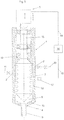
- Fig. 1 shows a mixing device 1 with a mixing chamber 12.
- a feed opening 2 for at least a first liquid plastic component (eg polyol) and a further feed opening 3 for at least a second liquid plastic component (eg isocyanate) can be seen which lead into the mixing chamber 12.
- the mixing device 1 is dynamic and comprises a stirrer 7 which can be rotated in the mixing chamber 12.
- the first and / or the second liquid plastic component can be mixed with a gas, for example air.
- the first liquid plastic component mixed with air in this example which is provided by a source 10
- the second liquid plastic component which is provided by a further source 11
- the rotating stirrer 7 mixes these two components.
- a discharge opening 4 for discharging the mixture consisting of first and second liquid plastic components from the mixing chamber 12 is provided adjacent to the tip of the stirrer 7.
- the mixture can be discharged from the discharge opening 4 in the direction of a nozzle 9 via a gap 6 remaining between the stirrer 7 and the discharge opening 4.
- An adjusting device 5 is provided, by means of which a relative movement between the discharge opening 4 and the stirrer 7 can be caused, and thus the gap 6 between the stirrer 7 and the discharge opening 4 can be changed.
- the adjusting device 5 has a stepper motor that engages via a shaft in a gearwheel which laterally engages in a screw sleeve arranged concentrically to the shaft 16. Rotation of the gearwheel by the stepper motor causes the screw sleeve to be adjusted axially, as a result of which the height of the stirrer 7 is adjusted, which adjusts the gap between the stirrer 7 and the discharge opening 4.
- a measurement of the adjustment that has taken place can be carried out and reported to the control device 14 via the schematically illustrated scale (the corresponding signal lines are not shown).
- a sensor 17 is provided, which is in a signal-conducting connection with a control device 14 via a signal line 18.
- the control device 14 is in turn connected to the adjusting device 5 via a control line 19, so that the control device 14 can adjust the gap 6 via the adjusting device 5 such that the pressure prevailing in the mixing device 1 or its mixing chamber 12 has a predetermined value of, for example less than 20 bar.
- other positions are also conceivable, e.g. on line 10.
- the pressure ratios are selected such that a constant pressure occurs in the mixing chamber 12 that is low enough that a foaming agent present in the mixture can foam out.
- this pressure change can be detected via the sensor 17 and the control device 14 can control the adjusting device 5 in such a way that this pressure change occurs a corresponding relative movement between stirrer 7 and discharge opening 4 is counteracted and the desired predetermined pressure is maintained in the mixing device 1.
- a corresponding pressure adjustment can take place after each application process or after each metering.
- a seal 15 (which can act as a seal in one direction or in both directions) surrounds the rotating shaft 16 of the stirrer 7 and seals the mixing chamber 12 in the region of the shaft 16 of the stirrer 7.
- the seal 15 can be made of Teflon, for example, and allow the axial movement of the rotating shaft 16 to run smoothly. Because the shaft 16 rotates and the seal 15 causes little friction, a very fine axial position adjustment of the stirrer 7 can be achieved. In particular, undesirable pressure fluctuations due to jerky axial displacement of the stirrer 7 as a result of a stick-slip effect can thereby be avoided.
- the rotation of the shaft 16 also facilitates the axial displacement of the stirrer 7.
- the seal 15 is preferably designed as a rotary and translational seal.
- Fig. 2 shows a detailed view of the tip of the stirrer 7 of the mixing device 1 according to Fig. 1 in a changed operating state, in which the stirrer 7 has been moved axially relative to the discharge opening 4 so far that it closes the discharge opening 4.
- the tip of the stirrer 7 is more pointed than the inclination of the end face 13 of the mixing chamber 12.
- the tip of the stirrer 7 only lies in a ring on the end face 13 and projects into the discharge opening 4 in order to close it off in a ring.
- Fig. 3 shows a mixing device 1 not according to the invention.
- the adjusting device 5 comprises a linear motor arranged on the shaft 16 of the stirrer 7, which can raise and lower the stirrer 7 directly axially and thus can cause the required relative movement between stirrer 7 and discharge opening 4 in order to change the gap 6 to the required extent. so that the pressure prevailing in the mixing device 1 or its mixing chamber 12 has the desired predetermined value.
- a measurement of the adjustment that has taken place can be carried out and reported to the control device 14 via the schematically illustrated scale (the corresponding signal lines are not shown).
- the adjusting device 5 can also comprise, for example, a cam drive, spindle drive or hydraulic drive which is known per se.
Description
Die vorliegende Erfindung betrifft eine Mischvorrichtung mit den Merkmalen des Oberbegriffs des Anspruchs 1.The present invention relates to a mixing device with the features of the preamble of claim 1.
Die Erfindung ist besonders bevorzugt bei der Herstellung geschäumter Kunststoffe (z.B. in Form von Kunststoffdichtungen) einsetzbar. Zur Erreichung einer gewünschten Mikrostruktur des Kunststoffes ist es erforderlich, dass in der Mischvorrichtung ein in einem bestimmten Druckfenster befindlicher Druck vorliegt. Ist eine Gasbeladung einer der beiden flüssigen Kunststoffkomponenten vorgesehen, hängt das bestimmte Druckfenster auch von der Gasbeladung ab. Variiert die gewünschte Austragsmenge aus der Ausbringöffnung, kann es zu einer stark schwankenden Qualität der Mikrostruktur des geschäumten Kunststoffes kommen.The invention is particularly preferably used in the production of foamed plastics (e.g. in the form of plastic seals). To achieve a desired microstructure of the plastic, it is necessary for the mixing device to have a pressure in a certain pressure window. If a gas loading of one of the two liquid plastic components is provided, the specific pressure window also depends on the gas loading. If the desired discharge quantity varies from the discharge opening, the quality of the microstructure of the foamed plastic can fluctuate greatly.
Es ist bekannt, dass es auch bei Schwankungen von Temperatur oder Viskosität der ersten und zweiten flüssigen Kunststoffkomponenten sowie durch Verschmutzungen in der Mischvorrichtung zu Veränderungen der Qualität der Mikrostruktur kommen kann.It is known that changes in the quality of the microstructure can also occur with fluctuations in temperature or viscosity of the first and second liquid plastic components and as a result of contamination in the mixing device.
Es sind daher bereits Maßnahmen bekannt, die Temperatur zu stabilisieren, Verschmutzungen zu entfernen und die Viskosität konstant zu halten und zur Anpassung von unterschiedlichen Austragsmengen unterschiedliche Düsen zu verwenden. So ist in der
In der
Auch in der
Die bisher bekannten Mischvorrichtungen haben sich nicht mit der Qualität der Mikrostruktur des aus der Mischung geschäumten Kunststoffs befasst, sodass diese bei Einsatz der bekannten Mischvorrichtungen teilweise stark variieren kann.The previously known mixing devices have not dealt with the quality of the microstructure of the plastic foamed from the mixture, so that this can vary greatly in some cases when using the known mixing devices.
Aufgabe der Erfindung ist es, dass eine gleichbleibende Qualität der Mikrostruktur des geschäumten Kunststoffes erreicht wird.The object of the invention is that a constant quality of the microstructure of the foamed plastic is achieved.
Diese Aufgabe wird durch eine Mischvorrichtung mit den Merkmalen des Anspruchs 1 gelöst.This object is achieved by a mixing device with the features of claim 1.
Die Erfindung beruht auf der überraschenden Erkenntnis, dass durch Konstanthalten des Druckes in der Mischvorrichtung automatisch eine gleichbleibende Qualität der Mikrostruktur des geschäumten Kunststoffes erreichbar ist, da so Änderungen der Austragsmenge, Schwankungen von Temperatur, Viskosität der ersten und zweiten flüssigen Kunststoffkomponenten, Verschmutzungen, welche ja in unvorhersehbarer Weise den Druck in der Mischvorrichtung beeinflussen, ausregelbar sind.The invention is based on the surprising finding that a constant quality of the microstructure of the foamed plastic can automatically be achieved by keeping the pressure in the mixing device constant, since changes in the discharge quantity, fluctuations in temperature, viscosity of the first and second liquid plastic components, soiling, which are yes influence the pressure in the mixing device in an unpredictable manner, can be regulated.
Die Höhe des Druckes in der Mischvorrichtung ist unter anderem abhängig von der Größe des Spaltes zwischen dem Rührer und der Ausbringöffnung sowie von der Größe der Ausbringöffnung. Weitere Einflussgrößen auf den Druck, wie z.B. die Dimensionierung der Düse, können als konstant angesehen werden. Durch Bestimmung des in der Mischvorrichtung herrschenden Druckes und Verstellen des Spaltes oder der Größe der Ausbringöffnung mittels Sensor, Regeleinrichtung und Verstellvorrichtung kann der Druck in der Mischvorrichtung auf einen gewünschten vorbestimmten Wert eingestellt und im Wesentlichen konstant gehalten werden.The level of pressure in the mixing device depends, among other things, on the size of the gap between the stirrer and the discharge opening and on the size of the discharge opening. Other influencing variables on the pressure, e.g. the dimensioning of the nozzle can be regarded as constant. By determining the pressure prevailing in the mixing device and adjusting the gap or the size of the discharge opening by means of a sensor, control device and adjusting device, the pressure in the mixing device can be set to a desired predetermined value and kept essentially constant.
Die vorgeschlagene Mischvorrichtung ist insbesondere vorteilhaft, wenn die Mischvorrichtung im Niederdruckbereich bei einem in der Mischvorrichtung herrschenden Druck von unter etwa 20 bar betrieben wird. In diesem Druckbereich kann ein beispielsweise in der ersten flüssigen Kunststoffkomponente vorhandenes Gas - z.B. in Polyol gelöste Luft - bereits in der Mischkammer ausperlen. Das bereits in der Mischkammer ausgeperlte Gas dient als Kondensationskeim und sorgt für ein gleichmäßiges Ausschäumen der Mischung beim Ausbringen aus der Mischvorrichtung.The proposed mixing device is particularly advantageous if the mixing device is operated in the low pressure range at a pressure in the mixing device of less than approximately 20 bar. In this pressure range, for example, a gas present in the first liquid plastic component - e.g. Air dissolved in polyol - already bubble out in the mixing chamber. The gas that has already bubbled out in the mixing chamber serves as a condensation nucleus and ensures that the mixture is evenly foamed out when it is discharged from the mixing device.
Durch Versuche wurde festgestellt, dass mit der vorgeschlagenen Mischvorrichtung eine gleichbleibende Mikrostruktur für einen großen Bereich an unterschiedlichen Austragsmengen erreicht werden kann. So konnte beispielsweise bei einer Verdoppelung oder Verdreifachung der Ausbringmenge eine im Wesentlichen unveränderte Mikrostruktur und damit eine gleichbleibende Qualität der Mikrostruktur erzielt werden.Experiments have shown that the proposed mixing device can achieve a constant microstructure for a large range of different discharge quantities. For example, when doubling or tripling the application rate an essentially unchanged microstructure and thus a constant quality of the microstructure can be achieved.
Bei der ersten flüssigen Kunststoffkomponente kann es sich vorzugsweise um eine viskose Flüssigkeit handeln. Beispiele sind Polyole, Silikone, Epoxy, Polyester, Acrylate und MS-Polymere.The first liquid plastic component can preferably be a viscous liquid. Examples are polyols, silicones, epoxy, polyesters, acrylates and MS polymers.
Beispiele für die zweite flüssige Kunststoffkomponente sind Isocyanat und Silikone.Examples of the second liquid plastic component are isocyanate and silicones.
Beispiele für das Gas, mit dem die erste und/oder zweite flüssige Kunststoffkomponente vermischt sein kann, sind Luft, Stickstoff, Kohlendioxid.Examples of the gas with which the first and / or second liquid plastic component can be mixed are air, nitrogen, carbon dioxide.
Es kann vorgesehen sein, dass das Gas in der ersten und/oder zweiten flüssigen Kunststoffkomponente zumindest teilweise gelöst vorliegt.It can be provided that the gas is at least partially dissolved in the first and / or second liquid plastic component.
Weitere Beispiele für Systeme mit wenigstens 2 Komponenten sind:
- additionsvernetzendes Silikon mit Silikon als erste flüssige Kunststoffkomponente und Silikon als additionsvernetzendes Vernetzungsmittel
- kondensationsvernetztes Silikon z. B. mit Wasser und/oder Glykolen, oder gemäß der
DE 10 2008 011 986 A1 - Polyurethan (Ergebnis) mit Isocyanat als Härtungsmittel vernetzt. Die Polyolkomponente als Flüssigkeit kann z. B. Polyesterpolyole, Polyetherpolyole, Thiole, Glykole, Amine, Kettenverlängerer und Acrylate enthalten. Die Isocyanate können aromatisch (z.B. auf Basis MDI, TDI) sowie aliphatisch (z.B. auf Basis HDI, IPDI, 12 fach hydriertes MDI) sein.
- Polyisocyanorate, die zweite Komponente enthält die Trimerisierungskatalysatoren und ggf. noch Polyole, andere Substanzen mit aktivem Wasserstoff oder nicht reaktive Verdünner.
- 1K NCO terminierte Polyurethane mit Wasser und/oder Glykolen als Härtungs- oder Vernetzungsmittel (Boostersysteme)
- Epoxidharzsysteme
- Silanmodifizierte Polymere mit Wasser und/oder Glykolen in der B Komponente , z.B. MS Polymere
- Acrylate, radikalisch gehärtet
- ungesättige Polyesterharze, radikalisch gehärtet
- Vinylesterharze, radikalisch gehärtet
- addition-curing silicone with silicone as the first liquid plastic component and silicone as the addition-curing crosslinking agent
- condensation cross-linked silicone e.g. B. with water and / or glycols, or according to the
DE 10 2008 011 986 A1 - Polyurethane (result) cross-linked with isocyanate as a curing agent. The polyol component as a liquid can, for. B. polyester polyols, polyether polyols, thiols, glycols, amines, chain extenders and acrylates. The isocyanates can be aromatic (for example based on MDI, TDI) and aliphatic (for example based on HDI, IPDI, 12-fold hydrogenated MDI).
- Polyisocyanorate, the second component contains the trimerization catalysts and possibly also polyols, other substances with active hydrogen or non-reactive thinners.
- 1K NCO terminated polyurethanes with water and / or glycols as hardening or crosslinking agents (booster systems)
- Epoxy resin systems
- Silane-modified polymers with water and / or glycols in the B component, eg MS polymers
- Acrylates, radical hardened
- unsaturated polyester resins, radically hardened
- Vinyl ester resins, radically hardened
Gemäß einem bevorzugten Ausführungsbeispiel kann vorgesehen sein, dass der Rührer relativ zur Ausbringöffnung verfahrbar ausgebildet ist. Dabei kann vorgesehen sein, dass die Verstellvorrichtung mit dem Rührer verbunden ist, wobei durch die Verstellvorrichtung der Rührer relativ zur Ausbringöffnung bewegbar ist.According to a preferred embodiment, it can be provided that the stirrer is designed to be movable relative to the discharge opening. It can be provided that the adjusting device is connected to the stirrer, the stirrer being movable relative to the dispensing opening by the adjusting device.
Es kann vorgesehen sein, dass die Verstellvorrichtung einen Linearmotor umfasst, der vorzugsweise an einer Welle des Rührers angeordnet ist.It can be provided that the adjustment device comprises a linear motor, which is preferably arranged on a shaft of the stirrer.
Es kann vorgesehen sein, dass die Ausbringöffnung größenveränderbar ausgebildet ist. Dabei kann vorgesehen sein, dass die Verstellvorrichtung mit der Ausbringöffnung verbunden ist, wobei durch die Verstellvorrichtung die Größe der Ausbringöffnung veränderbar ist. Die Verstellvorrichtung kann beispielsweise als irisartige Blende ausgebildet sein, wobei die Ausbringöffnung durch den freibleibenden zentralen Bereich der Irisblende gebildet wird. Alternativ kann die Verstellvorrichtung als ein elastisches Element in der Art einer Schlauchklemme ausgebildet sein, wobei die Ausbringöffnung durch die freibleibende lichte Weite im Schlauch gebildet ist.It can be provided that the discharge opening is designed to be resizable. It can be provided that the adjusting device is connected to the dispensing opening, the size of the dispensing opening being changeable by the adjusting device. The adjusting device can be designed, for example, as an iris-like diaphragm, the discharge opening being formed by the central region of the iris diaphragm which remains free. As an alternative, the adjusting device can be designed as an elastic element in the manner of a hose clamp, the discharge opening being formed by the free width remaining in the hose.
Ist die Mischvorrichtung längserstreckt ausgebildet, kann es vorteilhaft sein, wenn die wenigstens eine Zuführöffnung für die wenigstens eine erste flüssige Kunststoffkomponente und die zumindest eine weitere Zuführöffnung für die zumindest eine zweite flüssige Kunststoffkomponente an unterschiedlichen axialen Positionen der Mischvorrichtung angeordnet sind. Weil das Mischen der beiden flüssigen Kunststoffkomponenten erst im Bereich jener Zuführöffnung erfolgt, die näher bei der Ausbringöffnung liegt, kommt es im axial darüber liegenden Bereich zu keiner oder nur einer geringen Verschmutzung.If the mixing device is elongated, it can be advantageous if the at least one feed opening for the at least one first liquid plastic component and the at least one further feed opening for the at least one second liquid plastic component are arranged at different axial positions of the mixing device. Because the mixing of the two liquid plastic components only takes place in the area of the feed opening that is closer to the discharge opening, there is little or no contamination in the area axially above it.
Es kann vorgesehen sein, dass die Ausbringöffnung der Mischvorrichtung mit einer Düse verbunden ist.It can be provided that the discharge opening of the mixing device is connected to a nozzle.
Bevorzugt kann vorgesehen sein, dass der vorbestimmte Wert für den in der Mischvorrichtung herrschenden Druck kleiner als 20 bar, vorzugsweise kleiner als 10 bar, besonders bevorzugt etwa 2 bis etwa 4 bar, ist.It can preferably be provided that the predetermined value for the pressure prevailing in the mixing device is less than 20 bar, preferably less than 10 bar, particularly preferably about 2 to about 4 bar.
Schutz wird auch begehrt für eine Anordnung mit einer Mischvorrichtung nach wenigstens einem der vorangehenden Ausführungsbeispiele und einer Quelle für die wenigstens eine erste flüssige Kunststoffkomponente, die mit der wenigstens einen Zuführöffnung für die wenigstens eine erste flüssige Kunststoffkomponente verbunden ist, wobei vorzugsweise die wenigstens eine erste flüssige Kunststoffkomponente mit einem Gas vermischt ist, und einer Quelle für die zumindest eine zweite flüssige Kunststoffkomponente, die mit der zumindest einen weiteren Zuführöffnung für die zumindest eine zweite flüssige Kunststoffkomponente verbunden ist, wobei vorzugsweise die zumindest eine zweite flüssige Kunststoffkomponente mit einem Gas vermischt ist.Protection is also sought for an arrangement with a mixing device according to at least one of the preceding exemplary embodiments and a source for the at least one first liquid plastic component, which is connected to the at least one feed opening for the at least one first liquid plastic component, preferably the at least one a first liquid plastic component is mixed with a gas, and a source for the at least one second liquid plastic component, which is connected to the at least one further feed opening for the at least one second liquid plastic component, the at least one second liquid plastic component preferably mixing with a gas is.
Ausführungsformen der Erfindung werden anhand der Figuren diskutiert. Es zeigen:
- Fig. 1
- ein erstes Ausführungsbeispiel einer erfindungsgemäßen Mischvorrichtung,
- Fig. 2
- eine Detailansicht der Mischvorrichtung gemäß
Fig. 1 und - Fig. 3
- eine nicht erfindungsgemäße Mischvorrichtung.
- Fig. 1
- a first embodiment of a mixing device according to the invention,
- Fig. 2
- a detailed view of the mixing device according
Fig. 1 and - Fig. 3
- a mixing device not according to the invention.
Zum Erzeugen der Mischung aus erster und zweiter flüssiger Kunststoffkomponente werden die in diesem Beispiel mit Luft vermischte erste flüssige Kunststoffkomponente, die von einer Quelle 10 bereitgestellt wird, durch die erste Zuführöffnung 2 und die zweite flüssige Kunststoffkomponente, die von einer weiteren Quelle 11 bereitgestellt wird, durch die zweite Zuführöffnung 3 an unterschiedlichen axialen Positionen der hier längserstreckt ausgebildeten Mischvorrichtung 1 eingebracht. Durch den rotierenden Rührer 7 kommt es zum Vermischen dieser beiden Komponenten.To produce the mixture of first and second liquid plastic components, the first liquid plastic component mixed with air in this example, which is provided by a
Benachbart zur Spitze des Rührers 7 ist eine Ausbringöffnung 4 zum Ausbringen der Mischung bestehend aus erster und zweiter flüssiger Kunststoffkomponente aus der Mischkammer 12 vorgesehen. Über einen zwischen Rührer 7 und Ausbringöffnung 4 verbleibenden Spalt 6 ist die Mischung aus der Ausbringöffnung 4 in Richtung einer Düse 9 ausbringbar.A
Es ist eine Verstellvorrichtung 5 vorgesehen, durch welche eine Relativbewegung zwischen Ausbringöffnung 4 und Rührer 7 hervorrufbar und damit der Spalt 6 zwischen Rührer 7 und Ausbringöffnung 4 veränderbar ist. Die Verstellvorrichtung 5 weist einen Schrittmotor auf, der über eine Welle in ein Zahnrad eingreift, das seitlich in eine konzentrisch zur Welle 16 angeordnete Schraubhülse eingreift. Ein Drehen des Zahnrads durch den Schrittmotor bewirkt ein axiales Verstellen der Schraubhülse, wodurch die Höheneinstellung des Rührers 7 erfolgt, was den Spalt zwischen Rührer 7 und Ausbringöffnung 4 einstellt. Über die schematisch dargestellte Skala kann eine Messung der erfolgten Verstellung erfolgen und an die Regeleinrichtung 14 gemeldet werden (die entsprechenden Signalleitungen sind nicht dargestellt). Während den Dosierungen wird in Richtung des schematisch dargestellten Pfeiles Luft in den Bereich oberhalb der Dichtung 15 eingebracht, was zu einem Anheben des Rührers 7 entgegen der Beaufschlagung durch den Kraftspeicher 8 bis zum durch die Schraubhülse definierten Anschlag führt. Wird der Luftdruck abgeschaltet, bewegt der Kraftspeicher 8 den Rührer 7 so weit in Richtung der Ausbringöffnung 4 (in dieser Darstellung nach unten), bis der Rührer 7 die Ausbringöffnung 4 verschließt.An
Zur Bestimmung eines in der Mischvorrichtung 1 bzw. deren Mischkammer 12 herrschenden Druckes ist ein Sensor 17 vorgesehen, der über eine Signalleitung 18 mit einer Regeleinrichtung 14 in signalleitender Verbindung steht. Die Regeleinrichtung 14 wiederum steht über eine Steuerleitung 19 mit der Verstelleinrichtung 5 in signalleitender Verbindung, sodass die Regeleinrichtung 14 über die Verstellvorrichtung 5 den Spalt 6 derart einstellen kann, dass der in der Mischvorrichtung 1 bzw. deren Mischkammer 12 herrschende Druck einen vorbestimmten Wert von beispielsweise kleiner 20 bar aufweist. Alternativ zur gezeigten Positionierung des Sensors 17 sind auch andere Positionierungen denkbar, z.B. in der Leitung 10.To determine a pressure prevailing in the mixing device 1 or its
Im vorliegenden Ausführungsbeispiel sind die Druckverhältnisse so gewählt, dass es in der Mischkammer 12 zu einem konstanten Druck kommt, der niedrig genug ist, dass ein in der Mischung vorhandenes Schäummittel ausschäumen kann.In the present exemplary embodiment, the pressure ratios are selected such that a constant pressure occurs in the mixing
Wenn sich während oder nach eines Ausbringvorganges der Mischung aus der Mischvorrichtung 1 der Druck in der Mischvorrichtung 1 bzw. deren Mischkammer 12 verändert, kann diese Druckänderung über den Sensor 17 erfasst werden und die Regeleinrichtung 14 kann die Verstellvorrichtung 5 derart ansteuern, dass dieser Druckänderung durch eine entsprechende Relativbewegung zwischen Rührer 7 und Ausbringöffnung 4 entgegengewirkt wird und der gewünschte vorbestimmte Druck in der Mischvorrichtung 1 aufrechterhalten wird. Insbesondere kann eine entsprechende Druckanpassung nach jedem Ausbringvorgang bzw. nach jeder Dosierung erfolgen.If the pressure in the mixing device 1 or its
Eine Dichtung 15 (die in einer Richtung oder in beide Richtungen dichtend wirken kann) umschließt dichtend die rotierende Welle 16 des Rührers 7 und dichtet die Mischkammer 12 im Bereich der Welle 16 des Rührers 7 ab. Die Dichtung 15 kann beispielsweise aus Teflon bestehen und eine leichtgängige axiale Bewegung der rotierenden Welle 16 ermöglichen. Dadurch, dass die Welle 16 rotiert und die Dichtung 15 eine geringe Reibung verursacht, kann eine sehr feine axiale Positionsanpassung des Rührers 7 erzielt werden. Insbesondere können dadurch ungewünschte Druckschwankungen durch ruckartigen axialen Versatz des Rührers 7 infolge eines Stick-Slip-Effekts vermieden werden. Durch die Rotation der Welle 16 wird auch das axiale Verschieben des Rührers 7 erleichtert. Vorzugsweise ist die Dichtung 15 als Rotations- und Translationsdichtung ausgebildet.A seal 15 (which can act as a seal in one direction or in both directions) surrounds the rotating
Anders als dargestellt kann die Verstellvorrichtung 5 zum Beispiel auch einen an sich bekannten Nockenantrieb, Spindelantrieb oder hydraulischen Antrieb umfassen.In contrast to the illustration, the adjusting
- 11
- MischvorrichtungMixing device
- 22nd
- erste Zuführöffnung für wenigstens eine erste flüssige Kunststoffkomponentefirst feed opening for at least one first liquid plastic component
- 33rd
- zweite Zuführöffnung für zumindest eine zweite flüssige Kunststoffkomponentesecond feed opening for at least one second liquid plastic component
- 44th
- AusbringöffnungDischarge opening
- 55
- VerstellvorrichtungAdjustment device
- 66
- Spaltgap
- 77
- RührerStirrer
- 88th
- KraftspeicherLift mechanism
- 99
- Düsejet
- 1010th
- Quelle für wenigstens eine erste flüssige KunststoffkomponenteSource for at least a first liquid plastic component
- 1111
- Quelle für zumindest eine zweite flüssige KunststoffkomponenteSource for at least a second liquid plastic component
- 1212th
- MischkammerMixing chamber
- 1313
- StirnflächeFace
- 1414
- RegeleinrichtungControl device
- 1515
- Dichtungpoetry
- 1616
- Wellewave
- 1717th
- Sensorsensor
- 1818th
- SignalleitungSignal line
- 1919th
- SteuerleitungControl line
Claims (10)
- A mixing device (1) having at least one first feed opening (2) for at least one first liquid plastics component, preferably charged with a gas, and having at least one second feed opening (3) for at least one second liquid plastics component, and a discharge opening (4) for discharging a mixture of the first and the second liquid plastics components that can be produced in the mixing device (1), the mixing device (1) having a rotating stirrer (7) for mixing the first and the second liquid plastics components, a gap (6) remaining between the stirrer (7) and the discharge opening (4), an adjusting device (5) being provided which changes either the gap (6) or the size of the discharge opening (4) by means of a relative movement between the discharge opening (4) and the stirrer (7), and a control means (14) being provided which is in signal-conducting connection with a sensor (17) for determining a pressure prevailing in a mixing chamber (12) of the mixing device (1), the control means (14) adjusting the gap (6) or the size of the discharge opening (4) by means of the adjusting device (5) such that the pressure prevailing in the mixing chamber (12) of the mixing device (1) has a predetermined value, characterized in that the adjusting device (5) has a stepper motor which engages via a shaft in a toothed wheel which laterally engages in a screw sleeve arranged concentrically to the shaft (16) of the stirrer (7), a rotation of the toothed wheel by the stepper motor causing an axial adjustment of the screw sleeve, as a result of which the height of the stirrer (7) is adjusted, which adjusts the gap between the stirrer (7) and discharge opening (4).
- The mixing device according to claim 1, wherein the stirrer (7) is designed to be movable relative to the discharge opening (4).
- The mixing device according to claim 2, wherein the adjusting device (5) is connected to the stirrer (7), wherein the stirrer (7) can be moved relative to the discharge opening (4) by means of the adjusting device (5).
- The mixing device according to at least one of the preceding claims, wherein the adjusting device (5) comprises a linear motor, which is preferably arranged on a shaft (16) of the stirrer (7).
- The mixing device according to claim 1, wherein the discharge opening (4) is resizable.
- The mixing device according to claim 5, wherein the adjusting device (5) is connected to the discharge opening (4), wherein the size of the discharge opening (4) can be changed by the adjusting device (5).
- The mixing device according to at least one of the preceding claims, wherein the mixing device (1) is elongate and the at least one feed opening (2) for the at least one first liquid plastics component and the at least one further feed opening (3) for the at least one second liquid plastics component are arranged at different axial positions of the mixing device (1).
- The mixing device according to at least one of the preceding claims, wherein the discharge opening (4) of the mixing device (1) is connected to a nozzle (9).
- The mixing device according to at least one of the preceding claims, wherein the predetermined value for the pressure prevailing in the mixing device (1) is less than 20 bar, preferably less than 10 bar, particularly preferably approximately 2 to approximately 4 bar.
- An arrangement having a mixing device (1) according to at least one of the preceding claims and- a source (10) for the at least one first liquid plastics component, which is connected to the at least one feed opening (2) for the at least one first liquid plastics component, wherein the at least one first liquid plastics component is preferably mixed with a gas, and- a source (11) for the at least one second liquid plastics component, which is connected to the at least one additional feed opening (3) for the at least one second liquid plastics component, wherein the at least one second liquid plastics component is preferably mixed with a gas.
Applications Claiming Priority (2)
| Application Number | Priority Date | Filing Date | Title |
|---|---|---|---|
| ATA436/2015A AT516947B1 (en) | 2015-07-03 | 2015-07-03 | mixing device |
| PCT/AT2016/050228 WO2017004637A1 (en) | 2015-07-03 | 2016-06-24 | Mixing device with adjustment device for gap setting |
Publications (2)
| Publication Number | Publication Date |
|---|---|
| EP3317062A1 EP3317062A1 (en) | 2018-05-09 |
| EP3317062B1 true EP3317062B1 (en) | 2020-05-06 |
Family
ID=56497505
Family Applications (1)
| Application Number | Title | Priority Date | Filing Date |
|---|---|---|---|
| EP16741219.6A Active EP3317062B1 (en) | 2015-07-03 | 2016-06-24 | Mixing device with adjustment device for gap setting between stirrer and discharge opening |
Country Status (11)
| Country | Link |
|---|---|
| US (1) | US11034059B2 (en) |
| EP (1) | EP3317062B1 (en) |
| JP (1) | JP6573998B2 (en) |
| KR (1) | KR102066360B1 (en) |
| CN (1) | CN107889477A (en) |
| AT (1) | AT516947B1 (en) |
| AU (1) | AU2016291291B2 (en) |
| ES (1) | ES2792023T3 (en) |
| RU (1) | RU2693156C1 (en) |
| SG (1) | SG11201800040XA (en) |
| WO (1) | WO2017004637A1 (en) |
Families Citing this family (15)
| Publication number | Priority date | Publication date | Assignee | Title |
|---|---|---|---|---|
| AT517337B1 (en) * | 2015-07-03 | 2017-01-15 | Sonderhoff Engineering Gmbh | mixing device |
| DE102018008035A1 (en) * | 2017-10-20 | 2019-04-25 | Hilger U. Kern Gmbh | Device for mixing two or more components and method for calibrating such |
| AT519978B1 (en) * | 2017-12-19 | 2018-12-15 | Sonderhoff Eng Gmbh | Device for producing plastic parts |
| EP3727787A1 (en) * | 2018-02-23 | 2020-10-28 | Sealed Air Corporation (US) | Foam-in-bag systems and components thereof |
| CN111132811A (en) * | 2018-06-04 | 2020-05-08 | 耐克创新有限合伙公司 | Method and system for mixing and dispensing viscous material to create an additive structure |
| DE102018121323A1 (en) * | 2018-08-31 | 2020-03-05 | Hochtechnic GmbH | Device for filling molds with reactive resins |
| CN110065231A (en) * | 2019-04-29 | 2019-07-30 | 华侨大学 | A kind of 3D printer based on manostatic technique |
| DE102019114743A1 (en) * | 2019-06-03 | 2020-12-03 | Hilger U. Kern Gmbh | DEVICE FOR MIXING TWO OR MORE COMPONENTS AND METHOD FOR CALIBRATING SUCH |
| DE102019208475A1 (en) * | 2019-06-11 | 2020-12-17 | Henkel Ag & Co. Kgaa | Device for producing and processing a multicomponent mixture and method for operating such a device |
| DE102020123521A1 (en) * | 2020-09-09 | 2022-03-10 | Kraussmaffei Technologies Gmbh | DEVICE AND METHOD FOR MIXING AT LEAST TWO CHEMICALLY REACTIVE PLASTIC COMPONENTS |
| DE102021117879A1 (en) | 2021-07-12 | 2023-01-12 | Hilger U. Kern Gmbh | DEVICE FOR PREPARING A LIQUID POLYMER COMPONENT WITH A SPECIFIED AIR CONTENT, IN PARTICULAR FOR THE PRODUCTION OF A PLASTIC FOAM |
| EP4197735A1 (en) | 2021-12-20 | 2023-06-21 | Henkel AG & Co. KGaA | Method for preferably discontinuously dispensing a foamed or foamable plastic with direct gas loading |
| EP4197729A1 (en) | 2021-12-20 | 2023-06-21 | Henkel AG & Co. KGaA | Mixing device for providing a foamed or foamable plastic material |
| EP4197730A1 (en) | 2021-12-20 | 2023-06-21 | Henkel AG & Co. KGaA | Plastic dosing device and valve device for injecting gas into a mixing chamber of a plastic dosing device |
| EP4338922A1 (en) * | 2022-09-19 | 2024-03-20 | Ama.Gusberti S.r.l. | Dispensing head, station and method for molding polyurethane |
Family Cites Families (19)
| Publication number | Priority date | Publication date | Assignee | Title |
|---|---|---|---|---|
| GB986814A (en) | 1961-03-08 | 1965-03-24 | Pittsburgh Plate Glass Co | Method for forming resin foams |
| DE1949756A1 (en) * | 1969-10-02 | 1971-04-08 | Zippel & Co Kg R | Device for mixing two or more liquid plastic components |
| AT316850B (en) * | 1969-12-17 | 1974-07-25 | Semperit Ag | Device for batch mixing and conveying |
| DE3210978A1 (en) | 1982-03-25 | 1983-09-29 | Basf Ag, 6700 Ludwigshafen | MIXING DEVICE FOR MULTI-COMPONENT PLASTICS, ESPECIALLY POLYURETHANE |
| SU1796470A1 (en) | 1990-05-21 | 1993-02-23 | Ki Polt I | Polymeric material mixer |
| DE4235850B4 (en) | 1992-10-23 | 2008-11-06 | Edf Polymer-Applikation Maschinenfabrik Gmbh | Mixing head for processing multi-component plastic mixtures |
| CH687047A5 (en) | 1993-11-30 | 1996-08-30 | Hler Ag B | A method for controlling a work machine |
| EP0723843A3 (en) | 1995-01-27 | 1997-03-26 | Nordson Corp | Dispensing head for two-component foam with shutoff |
| US5938079A (en) | 1995-01-27 | 1999-08-17 | Nordson Corporation | Dispensing head for two-component foam with shutoff |
| JPH1029213A (en) * | 1996-07-15 | 1998-02-03 | Toray Dow Corning Silicone Co Ltd | Liquid material continuous mixing apparatus |
| RU2119504C1 (en) | 1997-09-03 | 1998-09-27 | Олег Владимирович Кононов | Process of processing of polymer material and gear for its implementation |
| DE19848357A1 (en) * | 1998-10-21 | 2000-04-27 | Edf Polymer Applikation Maschi | Mixing head for processing multi-component plastic mixtures |
| US6210030B1 (en) | 1999-06-15 | 2001-04-03 | Jean-Pierre Ibar | Method and apparatus to control viscosity of molten plastics prior to a molding operation |
| DE10242100A1 (en) | 2002-09-11 | 2004-03-25 | Hennecke Gmbh | Continuous mixing of polyol and isocyanate to produce reactive polyurethane mixture involves use of an impeller mixer with a specified number of angled blades in planes along the shaft |
| DE202005013008U1 (en) * | 2005-08-16 | 2005-11-10 | Intec Bielenberg Gmbh & Co Kg | Mixer and dispenser for two-component adhesives has housing at its base which contains mixing chamber, mixer head mounted on motor-driven shaft being mounted so that it can be raised and lowered in chamber |
| JP5105900B2 (en) | 2007-01-29 | 2012-12-26 | 有限会社サン・イースト・リサーチ | A polyurethane foam manufacturing method that has no pinholes and allows the cell size to be freely controlled. |
| DE102008011986A1 (en) | 2008-02-29 | 2009-09-10 | Sonderhoff Chemicals Gmbh | Condensation-crosslinking silicone foams |
| DE102012002047A1 (en) * | 2011-03-12 | 2012-09-13 | Oerlikon Textile Gmbh & Co. Kg | Dynamic mixer for blending polymer melt during melt spinning process for manufacturing synthetic threads, has sensor device arranged in region of outlet to measure physical parameters of melt and connected with control device |
| AT512679B1 (en) | 2012-04-05 | 2013-12-15 | Inova Lisec Technologiezentrum | Device for mixing |
-
2015
- 2015-07-03 AT ATA436/2015A patent/AT516947B1/en active
-
2016
- 2016-06-24 SG SG11201800040XA patent/SG11201800040XA/en unknown
- 2016-06-24 JP JP2017566132A patent/JP6573998B2/en active Active
- 2016-06-24 EP EP16741219.6A patent/EP3317062B1/en active Active
- 2016-06-24 WO PCT/AT2016/050228 patent/WO2017004637A1/en active Application Filing
- 2016-06-24 KR KR1020187003028A patent/KR102066360B1/en active IP Right Grant
- 2016-06-24 US US15/740,609 patent/US11034059B2/en active Active
- 2016-06-24 ES ES16741219T patent/ES2792023T3/en active Active
- 2016-06-24 AU AU2016291291A patent/AU2016291291B2/en active Active
- 2016-06-24 CN CN201680038096.8A patent/CN107889477A/en active Pending
- 2016-06-24 RU RU2018104068A patent/RU2693156C1/en active
Non-Patent Citations (1)
| Title |
|---|
| None * |
Also Published As
| Publication number | Publication date |
|---|---|
| AT516947A4 (en) | 2016-10-15 |
| US11034059B2 (en) | 2021-06-15 |
| EP3317062A1 (en) | 2018-05-09 |
| AU2016291291B2 (en) | 2019-07-11 |
| KR102066360B1 (en) | 2020-01-14 |
| KR20180022958A (en) | 2018-03-06 |
| AU2016291291A1 (en) | 2017-12-21 |
| AT516947B1 (en) | 2016-10-15 |
| SG11201800040XA (en) | 2018-02-27 |
| CN107889477A (en) | 2018-04-06 |
| JP6573998B2 (en) | 2019-09-11 |
| RU2693156C1 (en) | 2019-07-01 |
| WO2017004637A1 (en) | 2017-01-12 |
| ES2792023T3 (en) | 2020-11-06 |
| JP2018527214A (en) | 2018-09-20 |
| US20180194037A1 (en) | 2018-07-12 |
Similar Documents
| Publication | Publication Date | Title |
|---|---|---|
| EP3317062B1 (en) | Mixing device with adjustment device for gap setting between stirrer and discharge opening | |
| EP3227010B1 (en) | Apparatus and method for loading a liquid with gas | |
| DE3019888C2 (en) | ||
| EP3317061B1 (en) | Mixing device with a pressure holding device, and related method | |
| WO2004076515A1 (en) | Method and device for producing a two-component lacquer mixture | |
| EP0001581A1 (en) | Process and apparatus for mixing and spraying reactants | |
| EP3317003B1 (en) | Coating agent valve | |
| DE1201041B (en) | Screw extruder for plastic masses, e.g. B. thermoplastics | |
| EP1539450B1 (en) | Method for mixing a polyol constituent and an isocyanate constituent | |
| EP3310543B2 (en) | Device and method for foaming a viscous material | |
| WO2007074139A1 (en) | Apparatus and process for forming an adhesive and/or sealant composition, adhesive and/or sealant composition produced in this way and adhesive-bonded substrates | |
| DE10322998B4 (en) | Twin component paint preparation for a robot vehicle paint spraying assembly and especially a polyurethane paint emulsion pumps the two components under a low pressure to a mixer followed by a homogenizer | |
| DE19933440A1 (en) | Dispersing nozzle with variable throughput | |
| EP1252005B1 (en) | Injection nozzle for mixing heads of reaction casting machines | |
| EP0628390B1 (en) | Proportioning and conveyer pump and employment of such a pump for making moulded resin bodies | |
| DE1579001A1 (en) | Screw machine for melting plastic granulates | |
| DE102009055665A1 (en) | Method and apparatus for high pressure mixing of filled polyurethane resins | |
| DE202019000576U1 (en) | Device for applying medium to high viscosity liquid materials | |
| EP3338992B1 (en) | Method for injection moulding of plastic articles | |
| DE202023101189U1 (en) | Device for producing, mixing and discharging at least one polymer compound | |
| DE102022115955A1 (en) | Dosing pump with stroke adjustment | |
| DE102022128614A1 (en) | ROTATABLY MOUNTED COMPONENT AND METHOD FOR OPERATING IT | |
| EP4197730A1 (en) | Plastic dosing device and valve device for injecting gas into a mixing chamber of a plastic dosing device | |
| EP0897063A2 (en) | Device for delivering elastomeric material | |
| WO2019170870A1 (en) | Injection nozzle, mixing head containing such a nozzle, and device and method for regulating the application pressure of a material when exiting from a nozzle |
Legal Events
| Date | Code | Title | Description |
|---|---|---|---|
| STAA | Information on the status of an ep patent application or granted ep patent |
Free format text: STATUS: THE INTERNATIONAL PUBLICATION HAS BEEN MADE |
|
| PUAI | Public reference made under article 153(3) epc to a published international application that has entered the european phase |
Free format text: ORIGINAL CODE: 0009012 |
|
| STAA | Information on the status of an ep patent application or granted ep patent |
Free format text: STATUS: REQUEST FOR EXAMINATION WAS MADE |
|
| 17P | Request for examination filed |
Effective date: 20180126 |
|
| AK | Designated contracting states |
Kind code of ref document: A1 Designated state(s): AL AT BE BG CH CY CZ DE DK EE ES FI FR GB GR HR HU IE IS IT LI LT LU LV MC MK MT NL NO PL PT RO RS SE SI SK SM TR |
|
| AX | Request for extension of the european patent |
Extension state: BA ME |
|
| STAA | Information on the status of an ep patent application or granted ep patent |
Free format text: STATUS: EXAMINATION IS IN PROGRESS |
|
| 17Q | First examination report despatched |
Effective date: 20180827 |
|
| DAV | Request for validation of the european patent (deleted) | ||
| DAX | Request for extension of the european patent (deleted) | ||
| GRAP | Despatch of communication of intention to grant a patent |
Free format text: ORIGINAL CODE: EPIDOSNIGR1 |
|
| STAA | Information on the status of an ep patent application or granted ep patent |
Free format text: STATUS: GRANT OF PATENT IS INTENDED |
|
| RIC1 | Information provided on ipc code assigned before grant |
Ipc: B29B 7/40 20060101AFI20191107BHEP Ipc: B29B 7/72 20060101ALI20191107BHEP Ipc: B29B 7/74 20060101ALI20191107BHEP Ipc: B29B 7/76 20060101ALN20191107BHEP |
|
| INTG | Intention to grant announced |
Effective date: 20191210 |
|
| GRAS | Grant fee paid |
Free format text: ORIGINAL CODE: EPIDOSNIGR3 |
|
| GRAA | (expected) grant |
Free format text: ORIGINAL CODE: 0009210 |
|
| STAA | Information on the status of an ep patent application or granted ep patent |
Free format text: STATUS: THE PATENT HAS BEEN GRANTED |
|
| RAP1 | Party data changed (applicant data changed or rights of an application transferred) |
Owner name: HENKEL AG & CO. KGAA |
|
| AK | Designated contracting states |
Kind code of ref document: B1 Designated state(s): AL AT BE BG CH CY CZ DE DK EE ES FI FR GB GR HR HU IE IS IT LI LT LU LV MC MK MT NL NO PL PT RO RS SE SI SK SM TR |
|
| REG | Reference to a national code |
Ref country code: GB Ref legal event code: FG4D Free format text: NOT ENGLISH |
|
| REG | Reference to a national code |
Ref country code: CH Ref legal event code: EP Ref country code: AT Ref legal event code: REF Ref document number: 1266050 Country of ref document: AT Kind code of ref document: T Effective date: 20200515 |
|
| REG | Reference to a national code |
Ref country code: DE Ref legal event code: R096 Ref document number: 502016009875 Country of ref document: DE |
|
| REG | Reference to a national code |
Ref country code: IE Ref legal event code: FG4D Free format text: LANGUAGE OF EP DOCUMENT: GERMAN |
|
| REG | Reference to a national code |
Ref country code: LT Ref legal event code: MG4D |
|
| REG | Reference to a national code |
Ref country code: NL Ref legal event code: MP Effective date: 20200506 |
|
| PG25 | Lapsed in a contracting state [announced via postgrant information from national office to epo] |
Ref country code: SE Free format text: LAPSE BECAUSE OF FAILURE TO SUBMIT A TRANSLATION OF THE DESCRIPTION OR TO PAY THE FEE WITHIN THE PRESCRIBED TIME-LIMIT Effective date: 20200506 Ref country code: IS Free format text: LAPSE BECAUSE OF FAILURE TO SUBMIT A TRANSLATION OF THE DESCRIPTION OR TO PAY THE FEE WITHIN THE PRESCRIBED TIME-LIMIT Effective date: 20200906 Ref country code: NO Free format text: LAPSE BECAUSE OF FAILURE TO SUBMIT A TRANSLATION OF THE DESCRIPTION OR TO PAY THE FEE WITHIN THE PRESCRIBED TIME-LIMIT Effective date: 20200806 Ref country code: FI Free format text: LAPSE BECAUSE OF FAILURE TO SUBMIT A TRANSLATION OF THE DESCRIPTION OR TO PAY THE FEE WITHIN THE PRESCRIBED TIME-LIMIT Effective date: 20200506 Ref country code: GR Free format text: LAPSE BECAUSE OF FAILURE TO SUBMIT A TRANSLATION OF THE DESCRIPTION OR TO PAY THE FEE WITHIN THE PRESCRIBED TIME-LIMIT Effective date: 20200807 Ref country code: PT Free format text: LAPSE BECAUSE OF FAILURE TO SUBMIT A TRANSLATION OF THE DESCRIPTION OR TO PAY THE FEE WITHIN THE PRESCRIBED TIME-LIMIT Effective date: 20200907 Ref country code: LT Free format text: LAPSE BECAUSE OF FAILURE TO SUBMIT A TRANSLATION OF THE DESCRIPTION OR TO PAY THE FEE WITHIN THE PRESCRIBED TIME-LIMIT Effective date: 20200506 |
|
| REG | Reference to a national code |
Ref country code: ES Ref legal event code: FG2A Ref document number: 2792023 Country of ref document: ES Kind code of ref document: T3 Effective date: 20201106 |
|
| PG25 | Lapsed in a contracting state [announced via postgrant information from national office to epo] |
Ref country code: HR Free format text: LAPSE BECAUSE OF FAILURE TO SUBMIT A TRANSLATION OF THE DESCRIPTION OR TO PAY THE FEE WITHIN THE PRESCRIBED TIME-LIMIT Effective date: 20200506 Ref country code: LV Free format text: LAPSE BECAUSE OF FAILURE TO SUBMIT A TRANSLATION OF THE DESCRIPTION OR TO PAY THE FEE WITHIN THE PRESCRIBED TIME-LIMIT Effective date: 20200506 Ref country code: BG Free format text: LAPSE BECAUSE OF FAILURE TO SUBMIT A TRANSLATION OF THE DESCRIPTION OR TO PAY THE FEE WITHIN THE PRESCRIBED TIME-LIMIT Effective date: 20200806 Ref country code: RS Free format text: LAPSE BECAUSE OF FAILURE TO SUBMIT A TRANSLATION OF THE DESCRIPTION OR TO PAY THE FEE WITHIN THE PRESCRIBED TIME-LIMIT Effective date: 20200506 |
|
| PG25 | Lapsed in a contracting state [announced via postgrant information from national office to epo] |
Ref country code: NL Free format text: LAPSE BECAUSE OF FAILURE TO SUBMIT A TRANSLATION OF THE DESCRIPTION OR TO PAY THE FEE WITHIN THE PRESCRIBED TIME-LIMIT Effective date: 20200506 Ref country code: AL Free format text: LAPSE BECAUSE OF FAILURE TO SUBMIT A TRANSLATION OF THE DESCRIPTION OR TO PAY THE FEE WITHIN THE PRESCRIBED TIME-LIMIT Effective date: 20200506 |
|
| PG25 | Lapsed in a contracting state [announced via postgrant information from national office to epo] |
Ref country code: SM Free format text: LAPSE BECAUSE OF FAILURE TO SUBMIT A TRANSLATION OF THE DESCRIPTION OR TO PAY THE FEE WITHIN THE PRESCRIBED TIME-LIMIT Effective date: 20200506 Ref country code: DK Free format text: LAPSE BECAUSE OF FAILURE TO SUBMIT A TRANSLATION OF THE DESCRIPTION OR TO PAY THE FEE WITHIN THE PRESCRIBED TIME-LIMIT Effective date: 20200506 Ref country code: EE Free format text: LAPSE BECAUSE OF FAILURE TO SUBMIT A TRANSLATION OF THE DESCRIPTION OR TO PAY THE FEE WITHIN THE PRESCRIBED TIME-LIMIT Effective date: 20200506 Ref country code: RO Free format text: LAPSE BECAUSE OF FAILURE TO SUBMIT A TRANSLATION OF THE DESCRIPTION OR TO PAY THE FEE WITHIN THE PRESCRIBED TIME-LIMIT Effective date: 20200506 |
|
| REG | Reference to a national code |
Ref country code: CH Ref legal event code: PL |
|
| REG | Reference to a national code |
Ref country code: DE Ref legal event code: R097 Ref document number: 502016009875 Country of ref document: DE |
|
| PG25 | Lapsed in a contracting state [announced via postgrant information from national office to epo] |
Ref country code: SK Free format text: LAPSE BECAUSE OF FAILURE TO SUBMIT A TRANSLATION OF THE DESCRIPTION OR TO PAY THE FEE WITHIN THE PRESCRIBED TIME-LIMIT Effective date: 20200506 Ref country code: PL Free format text: LAPSE BECAUSE OF FAILURE TO SUBMIT A TRANSLATION OF THE DESCRIPTION OR TO PAY THE FEE WITHIN THE PRESCRIBED TIME-LIMIT Effective date: 20200506 Ref country code: MC Free format text: LAPSE BECAUSE OF FAILURE TO SUBMIT A TRANSLATION OF THE DESCRIPTION OR TO PAY THE FEE WITHIN THE PRESCRIBED TIME-LIMIT Effective date: 20200506 |
|
| PLBE | No opposition filed within time limit |
Free format text: ORIGINAL CODE: 0009261 |
|
| STAA | Information on the status of an ep patent application or granted ep patent |
Free format text: STATUS: NO OPPOSITION FILED WITHIN TIME LIMIT |
|
| PG25 | Lapsed in a contracting state [announced via postgrant information from national office to epo] |
Ref country code: LU Free format text: LAPSE BECAUSE OF NON-PAYMENT OF DUE FEES Effective date: 20200624 |
|
| 26N | No opposition filed |
Effective date: 20210209 |
|
| REG | Reference to a national code |
Ref country code: BE Ref legal event code: MM Effective date: 20200630 |
|
| GBPC | Gb: european patent ceased through non-payment of renewal fee |
Effective date: 20200806 |
|
| PG25 | Lapsed in a contracting state [announced via postgrant information from national office to epo] |
Ref country code: LI Free format text: LAPSE BECAUSE OF NON-PAYMENT OF DUE FEES Effective date: 20200630 Ref country code: CH Free format text: LAPSE BECAUSE OF NON-PAYMENT OF DUE FEES Effective date: 20200630 Ref country code: IE Free format text: LAPSE BECAUSE OF NON-PAYMENT OF DUE FEES Effective date: 20200624 |
|
| PG25 | Lapsed in a contracting state [announced via postgrant information from national office to epo] |
Ref country code: BE Free format text: LAPSE BECAUSE OF NON-PAYMENT OF DUE FEES Effective date: 20200630 Ref country code: SI Free format text: LAPSE BECAUSE OF FAILURE TO SUBMIT A TRANSLATION OF THE DESCRIPTION OR TO PAY THE FEE WITHIN THE PRESCRIBED TIME-LIMIT Effective date: 20200506 |
|
| PG25 | Lapsed in a contracting state [announced via postgrant information from national office to epo] |
Ref country code: GB Free format text: LAPSE BECAUSE OF NON-PAYMENT OF DUE FEES Effective date: 20200806 |
|
| PG25 | Lapsed in a contracting state [announced via postgrant information from national office to epo] |
Ref country code: MT Free format text: LAPSE BECAUSE OF FAILURE TO SUBMIT A TRANSLATION OF THE DESCRIPTION OR TO PAY THE FEE WITHIN THE PRESCRIBED TIME-LIMIT Effective date: 20200506 Ref country code: CY Free format text: LAPSE BECAUSE OF FAILURE TO SUBMIT A TRANSLATION OF THE DESCRIPTION OR TO PAY THE FEE WITHIN THE PRESCRIBED TIME-LIMIT Effective date: 20200506 |
|
| PG25 | Lapsed in a contracting state [announced via postgrant information from national office to epo] |
Ref country code: MK Free format text: LAPSE BECAUSE OF FAILURE TO SUBMIT A TRANSLATION OF THE DESCRIPTION OR TO PAY THE FEE WITHIN THE PRESCRIBED TIME-LIMIT Effective date: 20200506 |
|
| REG | Reference to a national code |
Ref country code: AT Ref legal event code: MM01 Ref document number: 1266050 Country of ref document: AT Kind code of ref document: T Effective date: 20210624 |
|
| PG25 | Lapsed in a contracting state [announced via postgrant information from national office to epo] |
Ref country code: AT Free format text: LAPSE BECAUSE OF NON-PAYMENT OF DUE FEES Effective date: 20210624 |
|
| P01 | Opt-out of the competence of the unified patent court (upc) registered |
Effective date: 20230530 |
|
| PGFP | Annual fee paid to national office [announced via postgrant information from national office to epo] |
Ref country code: FR Payment date: 20230630 Year of fee payment: 8 Ref country code: DE Payment date: 20230620 Year of fee payment: 8 Ref country code: CZ Payment date: 20230619 Year of fee payment: 8 |
|
| PGFP | Annual fee paid to national office [announced via postgrant information from national office to epo] |
Ref country code: TR Payment date: 20230619 Year of fee payment: 8 |
|
| PGFP | Annual fee paid to national office [announced via postgrant information from national office to epo] |
Ref country code: IT Payment date: 20230623 Year of fee payment: 8 Ref country code: ES Payment date: 20230830 Year of fee payment: 8 |