EP3317040B1 - Device for welding components by means of ultrasound by torsional vibrations - Google Patents
Device for welding components by means of ultrasound by torsional vibrations Download PDFInfo
- Publication number
- EP3317040B1 EP3317040B1 EP16736803.4A EP16736803A EP3317040B1 EP 3317040 B1 EP3317040 B1 EP 3317040B1 EP 16736803 A EP16736803 A EP 16736803A EP 3317040 B1 EP3317040 B1 EP 3317040B1
- Authority
- EP
- European Patent Office
- Prior art keywords
- sonotrode
- temperature control
- supporting
- sonotrode head
- torsion axis
- Prior art date
- Legal status (The legal status is an assumption and is not a legal conclusion. Google has not performed a legal analysis and makes no representation as to the accuracy of the status listed.)
- Active
Links
Images


Classifications
-
- B—PERFORMING OPERATIONS; TRANSPORTING
- B23—MACHINE TOOLS; METAL-WORKING NOT OTHERWISE PROVIDED FOR
- B23K—SOLDERING OR UNSOLDERING; WELDING; CLADDING OR PLATING BY SOLDERING OR WELDING; CUTTING BY APPLYING HEAT LOCALLY, e.g. FLAME CUTTING; WORKING BY LASER BEAM
- B23K20/00—Non-electric welding by applying impact or other pressure, with or without the application of heat, e.g. cladding or plating
- B23K20/10—Non-electric welding by applying impact or other pressure, with or without the application of heat, e.g. cladding or plating making use of vibrations, e.g. ultrasonic welding
- B23K20/106—Features related to sonotrodes
-
- B—PERFORMING OPERATIONS; TRANSPORTING
- B06—GENERATING OR TRANSMITTING MECHANICAL VIBRATIONS IN GENERAL
- B06B—METHODS OR APPARATUS FOR GENERATING OR TRANSMITTING MECHANICAL VIBRATIONS OF INFRASONIC, SONIC, OR ULTRASONIC FREQUENCY, e.g. FOR PERFORMING MECHANICAL WORK IN GENERAL
- B06B3/00—Methods or apparatus specially adapted for transmitting mechanical vibrations of infrasonic, sonic, or ultrasonic frequency
-
- B—PERFORMING OPERATIONS; TRANSPORTING
- B29—WORKING OF PLASTICS; WORKING OF SUBSTANCES IN A PLASTIC STATE IN GENERAL
- B29C—SHAPING OR JOINING OF PLASTICS; SHAPING OF MATERIAL IN A PLASTIC STATE, NOT OTHERWISE PROVIDED FOR; AFTER-TREATMENT OF THE SHAPED PRODUCTS, e.g. REPAIRING
- B29C65/00—Joining or sealing of preformed parts, e.g. welding of plastics materials; Apparatus therefor
- B29C65/02—Joining or sealing of preformed parts, e.g. welding of plastics materials; Apparatus therefor by heating, with or without pressure
- B29C65/08—Joining or sealing of preformed parts, e.g. welding of plastics materials; Apparatus therefor by heating, with or without pressure using ultrasonic vibrations
- B29C65/081—Joining or sealing of preformed parts, e.g. welding of plastics materials; Apparatus therefor by heating, with or without pressure using ultrasonic vibrations having a component of vibration not perpendicular to the welding surface
- B29C65/082—Angular, i.e. torsional ultrasonic welding
-
- B—PERFORMING OPERATIONS; TRANSPORTING
- B07—SEPARATING SOLIDS FROM SOLIDS; SORTING
- B07B—SEPARATING SOLIDS FROM SOLIDS BY SIEVING, SCREENING, SIFTING OR BY USING GAS CURRENTS; SEPARATING BY OTHER DRY METHODS APPLICABLE TO BULK MATERIAL, e.g. LOOSE ARTICLES FIT TO BE HANDLED LIKE BULK MATERIAL
- B07B2230/00—Specific aspects relating to the whole B07B subclass
- B07B2230/04—The screen or the screened materials being subjected to ultrasonic vibration
Definitions
- the present invention relates to a device for welding components by means of ultrasound according to the preamble of claim 1 (see for example US 2010/078115 A1 ), a support device for supporting a sonotrode head according to the preambles of the independent claims.
- Known support devices for sonotrode heads are attached at a point with minimal amplitude (so-called zero point support). In this way it can be achieved that as little ultrasonic energy as possible that is to be made available for the actual welding process is coupled out via the support device. An undesired rise in temperature on the support device can also be avoided in this way.
- US 3,184,841 for example a torsion sonotrode, which can be excited to torsion vibrations with the aid of ultrasonic transducers.
- the working surface of the annular welding tip runs perpendicular to the torsion axis.
- the sonotrode is supported on a vibration node by a mass.
- the WO 02/061895 A1 deals with the connection of electrical conductors, which can be achieved with torsion sonotrodes or longitudinal transducers, for example.
- the longitudinal transducer can be stored in a vibration node.
- a sonotrode is excited to torsional ultrasonic vibrations. It has a slot into which an engagement member of an anvil is inserted, so that a welding gap is formed for two plastic films to be welded. In the area of an engagement section, the engagement member has a weighing edge to which a wedge surface adjoins.
- a support segment arranged either on the engagement member or on a groove bottom has a conical tip on, which lies in the direction of the torsion axis and forms a zero point contact that does not resonate during welding.
- torsion sonotrodes contain projections which have working surfaces in the peripheral region.
- An annular surface is provided on each side of the work surfaces, which lies on a knot line with respect to a wavelength of a natural vibration of the torsion sonotrode.
- a support device encompasses these ring surfaces. Pressure forces are generated with the help of a pressure device.
- WO 2012/069413 A1 is a torsion transducer at a longitudinal position behind a sonotrode surrounded by a clamping ring, which forms a bearing for the torsion transducer.
- This clamping ring is typically arranged in a vibration node.
- a sonotrode of the device should be supported in such a way that there is no significant decoupling of the ultrasonic energy, regardless of the forces or torques acting on the sonotrode head.
- a device for welding components by means of ultrasound which contains a sonotrode with a sonotrode head and a support device.
- the sonotrode head can be excited by a vibration generator to produce torsional vibrations with respect to a torsion axis.
- at least one welding surface is arranged on the circumference of the sonotrode head with respect to the torsion axis.
- the support device supports the sonotrode head in a support area which contains a vibration node of the sonotrode head.
- the support area and the welding surface run at least partially in a common plane that extends perpendicular to the torsion axis.
- This configuration has the advantage that the position of the vibration node is practically not dependent on the forces or torques acting on the welding surface. Regardless of these forces or torques, there is no significant decoupling of the ultrasonic energy via the support device, so that a larger proportion of the ultrasonic energy is available for the actual purpose of welding.
- the support area forms only an area of the sonotrode head that is inner with respect to the torsion axis. Since the amplitude of the torsional vibrations is smaller in this inner area than in the outer areas, the ultrasound energy coupled out at the support device can thereby be reduced again.
- the sonotrode has a bore which penetrates the support area essentially perpendicular to the torsion axis
- the support device contains a support bolt which runs through the bore and which supports the sonotrode in the support area in the bore.
- a penetration “essentially perpendicular to the torsion axis” is understood here and below to mean that the bore penetrates the support area at an angle of 80 ° to 100 °.
- the said angle is preferably in the range from 85 ° to 95 °, even more preferably from 89 ° to 91 ° and is very particularly preferably 90 °. Because the closer this angle is to 90 °, the less ultrasonic energy is coupled out.
- the sonotrode and the support bolt are formed in one piece with one another.
- the sonotrode and the support axis are advantageously two separate components that have been joined together.
- the support bolt can support the sonotrode in the support area in the bore, for example by means of a transition fit, shrinking or pressing.
- the support pin cuts the torsion axis with particular advantage.
- the support bolt can support the region of the sonotrode head that is inner with respect to the torsion axis particularly effectively.
- the bore can taper in the direction of the support area.
- This formulation encompasses both conical areas of the bore and also embodiments in which the bore is cylindrical both in the support area and in two opposite mouth sections in which the bore opens out from the sonotrode, but the bore in the support area has a first inner diameter, which is smaller than a second inner diameter of the bore in the mouth sections.
- Such stepped areas are easier to manufacture than conical areas.
- the support bolt can expand in the direction of the support area.
- this formulation also includes support bolts with a central area with a first outside diameter and two end areas with second outside diameters, which are smaller than the first outside diameter. The longer the support area, the more stable the support. On the other hand, with increasing length of the support area, there is also an increasing and undesirable damping of the torsional vibrations. In practice, it has proven to be beneficial proven if the length of the support region along the support bolt is between 10% and 30%, preferably between 20% and 25% of the extent of the sonotrode head along the support bolt.
- the support pin can have two opposite ends, which are each received in a bearing opening.
- Each of the bearing openings can be designed as an opening of a respective one-piece bearing bush.
- each of the bearing openings can be formed by two bearing parts, for example by a bearing block and a clamping claw. By releasing such clamping claws from the bearing block, the support bolt is particularly easily accessible, for example in order to move the sonotrode into another position in which a different welding surface can be used for welding.
- the device contains a bearing block, in particular in one piece, which at least partially forms the two bearing openings mentioned.
- a bearing block is structurally particularly simple.
- the two bearing bushes are not integrally formed with one another.
- the device can furthermore contain a pressure device for generating forces acting essentially perpendicular to the torsion axis on the bearing block.
- forces acting essentially perpendicular to the torsion axis mean that the angle between forces and the torsion axis is in the range from 70 ° to 110 °, preferably from 80 ° to 100 °, particularly preferably from 85 ° to 95 °, and is very particularly preferably 90 °. In this way, the welding surface can be pressed against a first component to be connected to a second component. Because of the support device according to the invention, the forces generated by the pressure device do not cause any significant displacement of the position of the vibration node.
- the support bolt can be designed as a hollow bolt or also consist of solid material.
- a hollow bolt has the advantage of better vibration damping, while a bolt made of a solid material is mechanically more stable.
- the invention relates to the device for welding components with a support device which supports the sonotrode head in a support area which contains a vibration node of the sonotrode head.
- the vibration generator can be designed to excite the sonotrode head into torsional vibrations with respect to a torsion axis. At least one welding surface can be arranged on the circumferential side with respect to the torsion axis and / or at least one welding surface can be arranged on an end surface perpendicular to the torsion axis. Alternatively, the vibration generator can also be designed to excite the sonotrode head to produce longitudinal vibrations.
- the device has a temperature control device for temperature control, in particular for cooling or heating, of the sonotrode head.
- the temperature control device contains at least one temperature control feed through the support device for a temperature control medium and at least one temperature control element operatively connected to the temperature control supply, which is preferably arranged in the area of a welding surface of the sonotrode head.
- the operative connection can, for example, be in a fluid connection or an electrical connection. Since the temperature control feed is arranged in the support device which supports the sonotrode head in a support area which contains a vibration node of the sonotrode head, the temperature control feed is practically not affected by the ultrasonic vibrations.
- Cooling the sonotrode head in the area of a welding surface is particularly effective because most of the heat is generated during welding. Heating the sonotrode head in the area of a welding surface has also proven to be advantageous in some embodiments. Furthermore, tempering the sonotrode head has the advantage that the temperature and thus the resonance frequency can be kept relatively constant.
- the temperature control feed contains at least one feed channel through which a temperature control fluid can be introduced into the sonotrode head or can be carried out from the sonotrode head.
- the temperature control fluid forms the temperature control medium.
- the temperature control fluid in particular a cooling fluid or a heating fluid, can for example be a gas or a liquid, such as water.
- the at least one feed channel can open out at openings from the support device.
- the temperature control fluid can be introduced through a first opening and can be discharged again from a second opening.
- the temperature control element can contain at least one temperature control channel for the temperature control fluid, which is fluidly connected to the supply channel.
- the temperature control medium can be an electrical current. This can be inserted into the sonotrode head through an electrical line arranged in the support device, the electrical line forming the temperature control feed.
- the temperature control element can be an electrical temperature control element electrically connected to the electrical line.
- the electrical Temperature control element can be designed, for example, as a Peltier element to cool or heat the sonotrode head and / or as a heating wire to heat the sonotrode head.
- the support device contains a support pin as described above, which is designed as a hollow pin and forms the temperature control feed with a feed channel for a temperature control fluid contained therein.
- the feed channel can be arranged centered in the hollow bolt, for example, and can be cylindrical.
- the at least one feed channel can open out at openings which can be arranged at opposite ends of the support bolt or can also open out at the same end of the support bolt. If, according to the first aspect of the invention, the support area and the welding surface run at least partially in a common plane that extends perpendicular to the torsion axis, then the at least one feed channel and the temperature control channel can be formed by a common bore in the support bolt, which can be continuously cylindrical ,
- an electrical line can be led through the support bolt, for example to supply a Peltier element arranged in the sonotrode head with current.
- Devices are also covered by the first aspect of the invention in which the sonotrode is supported in the support region in a manner other than by a bore and a support bolt.
- the sonotrode head can have at least one, preferably a plurality of projections which are radial with respect to the torsion axis, at the ends of which a welding surface is formed in each case. With the help of such radial projections, large torsional vibration amplitudes can be achieved on the welding surfaces without the sonotrode head as a whole having to have a larger radius.
- the sonotrode head has exactly two projections which are radial and opposite one another with respect to the torsion axis, at the ends of which a welding surface is formed, the support bolt running essentially perpendicular to a connecting line which connects the two welding surfaces to one another.
- a “substantially vertical” course is understood here to mean that the angle between the support bolt and the connecting line is in the range from 70 ° to 110 °, preferably from 80 ° to 100 °, particularly preferably from 85 ° to 95 ° and very particularly preferably 90 ° is. Such an essentially vertical course ensures an even better transmission of forces and torques by the support device.
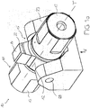
- the device 10 shown for welding components by means of ultrasound contains a sonotrode 11 with two end pieces 13 and a sonotrode head 12 arranged between them, which can be excited by means of vibration generators (not shown here) via the end pieces 13 to torsion vibrations with respect to a torsion axis T.
- the sonotrode head 12 has two projections 22 which are radial and opposite one another with respect to the torsion axis T. At the ends of the projections 22 a welding surface 14 is formed, with which a first component can be connected to a second component by welding. Both welding surfaces 14 are therefore arranged on the circumferential side with respect to the torsion axis T.
- the device 10 further includes a support device 15 which supports the sonotrode head 12 in a support area. This support area, which in Figure 1b is shown in more detail, contains a vibration node of the sonotrode head 12.
- the sectional view according to Figure 1b shows details of the support device 15.
- the sonotrode 11 has a cylindrical bore 17 which penetrates the support area 16 perpendicular to the torsion axis T and also perpendicular to a connecting line V connecting the two welding surfaces 14 to one another.
- the support device 15 further includes, and according to the invention, one extending through the bore 17 Support bolt 18, the central region 24 of which supports the sonotrode 11 in the support region 16 in the bore 17.
- the support pin 18 widens in the direction of its central area 24. In the exemplary embodiment shown here, the length of the support area 16 along the support pin 18 is approximately 20% of the extent of the sonotrode head 12 along the support pin 18.
- the support pin 18 is pressed into the bore 17 in the sonotrode 11 held. This can be achieved, for example, by cold shrinking, in which the support pin 18 is shrunk by cooling and is then inserted into the bore 17 through the bearing openings 29. During the subsequent reheating, the support pin 18 is pressed into the bore.
- the sonotrode 11 according to the invention is supported only in an area of the sonotrode head 12 that is inner with respect to the torsion axis T.
- the support region 16 forms only an inner region of the sonotrode head 12 with respect to the torsion axis T.
- the support region 16 and the welding surface 14 run in a common plane E, which extends perpendicular to the torsion axis T.
- the position of the vibration node practically does not depend on the forces or torques acting on the welding surfaces 14. Irrespective of these forces or torques, there is no significant decoupling of the ultrasound energy via the support device 15, so that a larger proportion of the ultrasound energy is available for the actual purpose of welding.
- the support pin 18 is designed in this embodiment as a hollow pin 18. Alternatively, the support pin 18 can also consist of solid material.
- the support pin 18 has two opposite ends 20 which are each received in a bearing opening 29 of a bearing bush 21 of a common, one-piece bearing block 23. In this way, forces and torques can be transferred to the bearing block.
- the support pin 18 permits particularly precise positioning of the sonotrode head 12.
- the device 10 can also contain a pressure device, not shown here, for generating forces K acting perpendicular to the torsion axis T on the bearing block 23. In this way, one of the welding surfaces 14 can be pressed against a first component which is to be connected to a second component.
- FIGS. 2a to 2e show a second device 10 'according to the invention for welding components by means of ultrasound.
- the device 10 contains a bearing block 26' with a groove-shaped recess in which a sonotrode 11 'is received.
- This sonotrode 11 ' also contains two end pieces 13' with an interposed sonotrode head 12 'with two projections 22', each of which has a welding surface 14 'at its ends. Via the end pieces 13 ', the sonotrode head 12' can be excited to torsion vibrations with respect to a torsion axis T by means of two vibration generators (not shown).
- Two opposite ends 20 'of a support bolt 18' are fastened to the bearing block 26 'with the aid of clamping claws 27'.
- the clamping claws 27 ' are fixed to the bearing block 26' by means of screws which are inserted into screw openings 28 '. By releasing the clamping claws 27 'from the bearing block 26', the support pin 18 'is particularly easily accessible.
- a pressure device not shown here, for example a pneumatic cylinder, forces K acting perpendicular to the torsion axis T can be exerted on the bearing block 26 ', as a result of which the Welding surface 14 'can be pressed against a first component to be connected to a second component.
- the device 10 contains two supports 30' with which the end pieces 13 'of the sonotrode 11' are held.
- These two supports 30 ' can consist of hard tissue panels, for example. They also contain a trough-shaped depression for supporting the end pieces 13 '. With the help of the supports 30 ', the position of the sonotrode 11' can be adjusted particularly precisely.
- the sonotrode 11 ' has a bore 17' which intersects the torsion axis T and thereby penetrates the sonotrode head 12 'perpendicular to the torsion axis T and also perpendicular to a connecting line V connecting the two projections 22'.
- a support pin 18 ' is inserted into the bore 17' and supports the sonotrode 11 'in a support region 16' in the bore 17 '.
- the support pin 18 ' is held by a transition fit so that it can be replaced if necessary, for example if it is worn, bent or broken.
- An oscillation node of the sonotrode head 12 ' is present in the support region 16'.
- Figure 2d shows a detailed perspective sectional view of the sonotrode head 12 '.
- the bore 17 'in the support region 16' has a first inner diameter, and in two opposite mouth sections 19 'it has a second inner diameter which is larger than the first inner diameter.
- the bore 17 'tapers in the direction of the support region 16'.
- the support pin 18 ' is shown in detail. In contrast to the support pin 18 of the first embodiment this support pin 18 'made of a solid material.
- the support pin 18 ' contains a central region 24' with a first outer diameter and two opposite end regions 25 'with a second outer diameter which is smaller than the first outer diameter.
- the support pin 18 'thus widens in the direction of the central region in which it supports the sonotrode head 12'.
- the length of the support region 16 'along the support bolt 18' is approximately 25% of the extent of the sonotrode head 12 'along the support bolt 18'.
- the sonotrode head 12 ′ is thereby supported only in an area of the sonotrode head 12 ′ that is inner with respect to the torsion axis T. Furthermore, the support region 16 ′ and the two welding surfaces 14 ′ run in a common plane E, which extends perpendicular to the torsion axis T.
- the clamping claws 27' can first be released from the bearing block 26 '. Due to the centering of the bore 17 'and the support bolt 18' and due to the overall symmetrical arrangement, the sonotrode 11 'can then simply be rotated together with the support bolt 18' by 180 ° about the torsion axis T, so that the ends 20 'in the Bearing openings 29 'are added. The clamping claws 27 'can then be fastened again to the bearing block 26'. This positioning is extremely precise due to the support bolt 18 '.
- the third device 10 "according to the invention is shown in comparison to that shown in FIGS Figures 2a to 2e shown device 10 'of the support bolt as a hollow bolt 18 ". It has a centered and continuously cylindrical Channel 31 "through which a temperature control fluid, in particular a cooling medium or a heating medium, for example water, can be introduced, passed through and executed again in the sonotrode head 12". In this way, temperature control, in particular cooling or heating, of the sonotrode head 12 "in the area of the welding surfaces 14" can be achieved.
- the channel 31 ′′ opens out at openings 32 ′′, 33 ′′ which are arranged at opposite ends 20 ′′ of the support bolt 18 ′′.
- the temperature control fluid can be introduced through a first opening 32 ′′ and again from a second opening 33 ′′
- this embodiment allows the sonotrode 11 "to be cooled in the area of the welding surfaces 14" where most of the heat is generated during welding.
- FIG 4 schematically shows a fourth exemplary embodiment according to the invention, in which a welding surface 14 '''is arranged on an end surface of the sonotrode head 12'''.
- the ends 20 '''of the support bolt 18''' are held in two bearing openings, not shown here.
- temperature control channels are also provided in the area of the welding surface 14''' and are fluid-connected to the feed channel 31 '''. In this way, the sonotrode head 11 '''can be cooled in the area of the welding surface 14'''.
- the sonotrode head 12 ''' can cause torsional vibrations with respect to a torsion axis T or longitudinal vibrations be excitable, wherein the support region 16 '''contains a torsional or longitudinal vibration node of the sonotrode head 12'''. Due to the arrangement of the support bolt 18 '''in this area, the supply of the temperature control fluid is not impaired.
Description
Die vorliegende Erfindung betrifft eine Vorrichtung zum Verschweissen von Bauteilen mittels Ultraschalls gemäß dem Oberbegriff des Anspruchs 1 (siehe z.B.
Bekannte Abstützeinrichtungen für Sonotrodenköpfe werden an einer Stelle mit minimaler Amplitude angebracht (sogenannte Nullpunktabstützung). Hierdurch kann erreicht werden, dass über die Abstützeinrichtung möglichst wenig Ultraschallenergie ausgekoppelt wird, die für den eigentlichen Schweissvorgang zur Verfügung gestellt werden soll. Auch ein ungewollter Temperaturanstieg an der Abstützeinrichtung kann hierdurch vermieden werden.Known support devices for sonotrode heads are attached at a point with minimal amplitude (so-called zero point support). In this way it can be achieved that as little ultrasonic energy as possible that is to be made available for the actual welding process is coupled out via the support device. An undesired rise in temperature on the support device can also be avoided in this way.
So offenbart die
Die
In der
Die in
Im Ausführungsbeispiel der
All diese bekannten Abstützeinrichtungen haben jedoch den Nachteil, dass die Position des Schwingungsknotens von den auf den Sonotrodenkopf einwirkenden Kräften und Drehmomenten abhängt. In aller Regel kann sich ein Schwingungsknoten um mehrere Millimeter verschieben. Dies führt zu einer ungewollten Auskopplung der Ultraschallenergie und den damit verbundenen, bereits oben beschriebenen Nachteilen.However, all of these known support devices have the disadvantage that the position of the vibration node depends on the forces and torques acting on the sonotrode head. As a rule, a vibration node can shift by several millimeters. This leads to an unwanted decoupling of the ultrasonic energy and the associated disadvantages already described above.
Es ist daher eine Aufgabe der vorliegenden Erfindung, eine Vorrichtung zum Verschweissen von Bauteilen mittels Ultraschalls bereitzustellen, welche die oben genannten Nachteile nicht aufweist. Insbesondere soll eine Sonotrode der Vorrichtung also derart abgestützt werden, dass es zu keiner nennenswerten Auskopplung der Ultraschallenergie kommt, und zwar unabhängig davon, welche Kräfte oder Drehmomente auf den Sonotrodenkopf einwirken.It is therefore an object of the present invention to provide a device for welding components using ultrasound, which does not have the disadvantages mentioned above. In particular, a sonotrode of the device should be supported in such a way that there is no significant decoupling of the ultrasonic energy, regardless of the forces or torques acting on the sonotrode head.
Diese und weitere Aufgaben werden gemäss der Erfindung gelöst durch eine Vorrichtung zum Verschweissen von Bauteilen mittels Ultraschalls entsprechend dem Anspruch 1, welche eine Sonotrode mit einem Sonotrodenkopf und eine Abstützeinrichtung enthält. Der Sonotrodenkopf ist von einem Schwingungserzeuger zu Torsionsschwingungen bezüglich einer Torsionsachse anregbar. Gemäss der Erfindung ist am Sonotrodenkopf bezüglich der Torsionsachse umfangseitig wenigstens eine Schweissfläche angeordnet. Die Abstützeinrichtung stützt den Sonotrodenkopf in einem Abstützbereich ab, der einen Schwingungsknoten des Sonotrodenkopfs enthält.These and other objects are achieved according to the invention by a device for welding components by means of ultrasound, which contains a sonotrode with a sonotrode head and a support device. The sonotrode head can be excited by a vibration generator to produce torsional vibrations with respect to a torsion axis. According to the invention, at least one welding surface is arranged on the circumference of the sonotrode head with respect to the torsion axis. The support device supports the sonotrode head in a support area which contains a vibration node of the sonotrode head.
Gemäss der Erfindung verlaufen der Abstützbereich und die Schweissfläche zumindest teilweise in einer gemeinsamen Ebene, die sich senkrecht zur Torsionsachse erstreckt. Diese Ausgestaltung hat den Vorteil, dass die Position des Schwingungsknotens praktisch nicht davon abhängt, welche Kräfte oder Drehmomente auf die Schweissfläche wirken. Unabhängig von diesen Kräften oder Drehmomenten entsteht also keine nennenswerte Auskoppelung der Ultraschallenergie über die Abstützeinrichtung, so dass ein grösserer Anteil der Ultraschallenergie für den eigentlichen Zweck des Verschweissens zur Verfügung steht.According to the invention, the support area and the welding surface run at least partially in a common plane that extends perpendicular to the torsion axis. This configuration has the advantage that the position of the vibration node is practically not dependent on the forces or torques acting on the welding surface. Regardless of these forces or torques, there is no significant decoupling of the ultrasonic energy via the support device, so that a larger proportion of the ultrasonic energy is available for the actual purpose of welding.
Gemäß der Erfindung bildet der Abstützbereich nur einen bezüglich der Torsionsachse inneren Bereich des Sonotrodenkopfs. Da in diesem inneren Bereich die Amplitude der Torsionsschwingungen kleiner ist als in äusseren Bereichen, kann hierdurch die an der Abstützeinrichtung ausgekoppelte Ultraschallenergie nochmals reduziert werden.According to the invention, the support area forms only an area of the sonotrode head that is inner with respect to the torsion axis. Since the amplitude of the torsional vibrations is smaller in this inner area than in the outer areas, the ultrasound energy coupled out at the support device can thereby be reduced again.
Gemäss der Erfindung weist die Sonotrode eine Bohrung auf, welche den Abstützbereich im Wesentlichen senkrecht zur Torsionsachse durchdringt, und die Abstützeinrichtung enthält einen durch die Bohrung verlaufenden Stützbolzen, welcher die Sonotrode im Abstützbereich in der Bohrung abstützt. Unter einer Durchdringung "im Wesentlichen senkrecht zur Torsionsachse" wird hier und im Folgenden verstanden, dass die Bohrung den Abstützbereich unter einem Winkel von 80° bis 100° durchdringt. Bevorzugt liegt der genannte Winkel im Bereich von 85° bis 95°, noch weiter bevorzugt von 89° bis 91° und ist ganz besonders bevorzugt 90°. Denn je näher dieser Winkel bei 90° liegt, desto weniger Ultraschallenergie wird ausgekoppelt. Auf diese Weise kann besonders einfach eine Abstützung nur in einem bezüglich der Torsionsachse inneren Bereich des Sonotrodenkopfs realisiert werden, wodurch die bereits oben erläuterten Vorteile erzielt werden können. Wie sich vollkommen überraschend herausgestellt hat, werden die akustischen Eigenschaften der Sonotrode durch die sie durchdringende Bohrung und durch den hierdurch verlaufenden Stützbolzen nicht nachteilig beeinflusst. Ein solcher Stützbolzen hat den Vorteil, dass die Sonotrode präzise eingesetzt werden kann, insbesondere, wenn die Sonotrode umpositioniert oder ausgetauscht wird.According to the invention, the sonotrode has a bore which penetrates the support area essentially perpendicular to the torsion axis, and the support device contains a support bolt which runs through the bore and which supports the sonotrode in the support area in the bore. A penetration “essentially perpendicular to the torsion axis” is understood here and below to mean that the bore penetrates the support area at an angle of 80 ° to 100 °. The said angle is preferably in the range from 85 ° to 95 °, even more preferably from 89 ° to 91 ° and is very particularly preferably 90 °. Because the closer this angle is to 90 °, the less ultrasonic energy is coupled out. In this way, support can be realized in a particularly simple manner only in an area of the sonotrode head that is inner with respect to the torsion axis, as a result of which the advantages already explained above can be achieved. As has been found to be completely surprising, the acoustic properties of the sonotrode are not adversely affected by the bore penetrating it and by the support bolt running through it. Such a support bolt has the advantage that the sonotrode can be used precisely, in particular if the sonotrode is repositioned or exchanged.
Es ist denkbar und liegt im Rahmen der Erfindung, dass die Sonotrode und der Stützbolzen miteinander einstückig ausgebildet sind. Vorteilhafterweise sind jedoch die Sonotrode und die Abstützachse zwei separate Bauelemente, die zusammengefügt wurden. Der Stützbolzen kann die Sonotrode im Abstützbereich in der Bohrung beispielsweise durch Übergangspassung, Schrumpfen oder Einpressen abstützen.It is conceivable and within the scope of the invention that the sonotrode and the support bolt are formed in one piece with one another. However, the sonotrode and the support axis are advantageously two separate components that have been joined together. The support bolt can support the sonotrode in the support area in the bore, for example by means of a transition fit, shrinking or pressing.
Mit besonderem Vorteil schneidet der Stützbolzen die Torsionsachse. Auf diese Weise kann der Stützbolzen besonders effektiv den bezüglich der Torsionsachse inneren Bereich des Sonotrodenkopfs abstützen.The support pin cuts the torsion axis with particular advantage. In this way, the support bolt can support the region of the sonotrode head that is inner with respect to the torsion axis particularly effectively.
Um eine Abstützung nur in einem bezüglich der Torsionsachse inneren Bereich des Sonotrodenkopfs zu ermöglichen, kann sich die Bohrung in Richtung des Abstützbereichs verjüngen. Diese Formulierung umfasst sowohl konische Bereiche der Bohrung als auch Ausführungsformen, bei denen die Bohrung sowohl im Abstützbereich als auch in zwei gegenüberliegenden Mündungsabschnitten, in denen die Bohrung aus der Sonotrode ausmündet, jeweils zylindrisch sind, wobei jedoch die Bohrung im Abstützbereich einen ersten Innendurchmesser aufweist, der kleiner ist als ein zweiter Innendurchmesser der Bohrung in den Mündungsabschnitten. Derartige stufenförmige Bereiche sind leichter herzustellen als konische Bereiche.In order to allow support only in an area of the sonotrode head that is inner with respect to the torsion axis, the bore can taper in the direction of the support area. This formulation encompasses both conical areas of the bore and also embodiments in which the bore is cylindrical both in the support area and in two opposite mouth sections in which the bore opens out from the sonotrode, but the bore in the support area has a first inner diameter, which is smaller than a second inner diameter of the bore in the mouth sections. Such stepped areas are easier to manufacture than conical areas.
Alternativ oder zusätzlich kann sich der Stützbolzen in Richtung des Abstützbereichs erweitern. Analog umfasst diese Formulierung auch Stützbolzen mit einem mittleren Bereich mit einem ersten Aussendurchmesser und zwei Endbereichen mit zweiten Aussendurchmessern, die kleiner sind als der erste Aussendurchmesser. Je länger der Abstützbereich ist, desto stabiler ist die Abstützung. Andererseits entsteht mit zunehmender Länge des Abstützbereichs aber auch eine zunehmende und unerwünschte Dämpfung der Torsionsschwingungen. In der Praxis hat es sich als vorteilhaft erwiesen, wenn die Länge des Abstützbereichs entlang des Stützbolzens zwischen 10 % und 30 %, bevorzugt zwischen 20 % und 25 % der Ausdehnung des Sonotrodenkopfs entlang des Stützbolzens beträgt.Alternatively or additionally, the support bolt can expand in the direction of the support area. Analogously, this formulation also includes support bolts with a central area with a first outside diameter and two end areas with second outside diameters, which are smaller than the first outside diameter. The longer the support area, the more stable the support. On the other hand, with increasing length of the support area, there is also an increasing and undesirable damping of the torsional vibrations. In practice, it has proven to be beneficial proven if the length of the support region along the support bolt is between 10% and 30%, preferably between 20% and 25% of the extent of the sonotrode head along the support bolt.
In weiteren vorteilhaften Ausführungsformen kann der Stützbolzen zwei gegenüberliegende Enden aufweisen, die in jeweils einer Lageröffnung aufgenommen sind. Auf diese Weise können Kräfte und Drehmomente, die beim Verschweissen entstehen, auf die Lagerung übertragen werden. Jede der Lageröffnungen kann als Öffnung einer jeweils einstückigen Lagerbuchse ausgebildet sein. Alternativ kann jede der Lageröffnungen durch zwei Lagerteile gebildet sein, beispielsweise durch einen Lagerblock und eine Klemmpratze. Durch Lösen solcher Klemmpratzen vom Lagerblock ist der Stützbolzen besonders einfach zugänglich, beispielsweise um die Sonotrode in eine andere Position zu überführen, in der eine andere Schweissfläche zum Verschweissen eingesetzt werden kann.In further advantageous embodiments, the support pin can have two opposite ends, which are each received in a bearing opening. In this way, forces and torques that arise during welding can be transferred to the bearing. Each of the bearing openings can be designed as an opening of a respective one-piece bearing bush. Alternatively, each of the bearing openings can be formed by two bearing parts, for example by a bearing block and a clamping claw. By releasing such clamping claws from the bearing block, the support bolt is particularly easily accessible, for example in order to move the sonotrode into another position in which a different welding surface can be used for welding.
Besonders vorteilhaft enthält die Vorrichtung einen insbesondere einstückigen Lagerblock, welcher die beiden genannten Lageröffnungen zumindest teilweise bildet. Ein derartiger einstückiger Lagerblock ist baulich besonders einfach. Alternativ dazu ist es aber auch denkbar und liegt ebenso im Rahmen der Erfindung, dass die beiden Lagerbuchsen nicht einstückig miteinander ausgebildet sind.Particularly advantageously, the device contains a bearing block, in particular in one piece, which at least partially forms the two bearing openings mentioned. Such a one-piece bearing block is structurally particularly simple. Alternatively, however, it is also conceivable and is also within the scope of the invention that the two bearing bushes are not integrally formed with one another.
Die Vorrichtung kann weiterhin eine Druckvorrichtung zur Erzeugung von im Wesentlichen senkrecht zur Torsionsachse wirkenden Kräften auf den Lagerblock enthalten. Unter "im Wesentlichen senkrecht zur Torsionsachse wirkenden Kräfte" wird hier und im Folgenden verstanden, dass der Winkel zwischen Kräften und Torsionsachse im Bereich von70° bis 110°, bevorzugt von 80° bis 100°, besonders bevorzugt von 85° bis 95° liegt und ist ganz besonders bevorzugt 90°. Auf diese Weise ist die Schweissfläche an ein mit einem zweiten Bauteil zu verbindendes erstes Bauteil andrückbar. Aufgrund der erfindungsgemässen Abstützeinrichtung bewirken die von der Druckvorrichtung erzeugten Kräfte keine nennenswerte Verschiebung der Lage des Schwingungsknotens.The device can furthermore contain a pressure device for generating forces acting essentially perpendicular to the torsion axis on the bearing block. Here and below, “forces acting essentially perpendicular to the torsion axis” mean that the angle between forces and the torsion axis is in the range from 70 ° to 110 °, preferably from 80 ° to 100 °, particularly preferably from 85 ° to 95 °, and is very particularly preferably 90 °. In this way, the welding surface can be pressed against a first component to be connected to a second component. Because of the support device according to the invention, the forces generated by the pressure device do not cause any significant displacement of the position of the vibration node.
Der Stützbolzen kann als Hohlbolzen ausgebildet sein oder auch aus Vollmaterial bestehen. Ein Hohlbolzen hat den Vorteil einer besseren Schwingungsdämpfung, während ein aus einem Vollmaterial bestehender Bolzen mechanisch stabiler ist.The support bolt can be designed as a hollow bolt or also consist of solid material. A hollow bolt has the advantage of better vibration damping, while a bolt made of a solid material is mechanically more stable.
In einem Aspekt der Erfindung betrifft die Erfindung die Vorrichtung zum Verschweissen von Bauteilen mit einer Abstützeinrichtung, welche den Sonotrodenkopf in einem Abstützbereich abstützt, der einen Schwingungsknoten des Sonotrodenkopfs enthält.In one aspect of the invention, the invention relates to the device for welding components with a support device which supports the sonotrode head in a support area which contains a vibration node of the sonotrode head.
Der Schwingungserzeuger kann zur Anregung des Sonotrodenkopfes zu Torsionsschwingungen bezüglich einer Torsionsachse ausgebildet sein. Dabei kann mindestens eine Schweissfläche bezüglich der Torsionsachse umfangsseitig und/oder mindestens eine Schweissfläche an einer zur Torsionsachse senkrechten Endfläche angeordnet sein. Alternativ kann der Schwingungserzeuger aber auch zur Anregung des Sonotrodenkopfes zu Längsschwingungen ausgebildet sein.The vibration generator can be designed to excite the sonotrode head into torsional vibrations with respect to a torsion axis. At least one welding surface can be arranged on the circumferential side with respect to the torsion axis and / or at least one welding surface can be arranged on an end surface perpendicular to the torsion axis. Alternatively, the vibration generator can also be designed to excite the sonotrode head to produce longitudinal vibrations.
In diesem Aspekt der Erfindung weist die Vorrichtung eine Temperiereinrichtung zur Temperierung, insbesondere zum Kühlen oder zum Heizen, des Sonotrodenkopfs auf. Die Temperiereinrichtung enthält mindestens eine durch die Abstützeinrichtung geführte Temperierzuführung für ein Temperiermedium und mindestens ein mit der Temperierzuführung wirkverbundenes Temperierelement, welches bevorzugt im Bereich einer Schweissfläche des Sonotrodenkopfs angeordnet ist. Wie weiter unten erläutert wird, kann die Wirkverbindung beispielsweise in einer Fluidverbindung oder einer elektrischen Verbindung bestehen. Da die Temperierzuführung in der Abstützeinrichtung angeordnet ist, welche den Sonotrodenkopf in einem Abstützbereich abstützt, der einen Schwingungsknoten des Sonotrodenkopfs enthält, wird die Temperierzuführung praktisch nicht von den Ultraschallschwingungen beeinträchtigt. Eine Kühlung des Sonotrodenkopfs im Bereich einer Schweissfläche ist besonders effektiv, da dort beim Schweissen die meiste Wärme entsteht. Auch ein Heizen des Sonotrodenkopfs im Bereich einer Schweissfläche hat sich in einigen Ausführungen als vorteilhaft erwiesen. Weiterhin hat das Temperieren der Sonotrodenkopfs den Vorteil, dass die Temperatur und damit auch die Resonanzfrequenz vergleichsweise konstant gehalten werden kann.In this aspect of the invention, the device has a temperature control device for temperature control, in particular for cooling or heating, of the sonotrode head. The temperature control device contains at least one temperature control feed through the support device for a temperature control medium and at least one temperature control element operatively connected to the temperature control supply, which is preferably arranged in the area of a welding surface of the sonotrode head. As will be explained further below, the operative connection can, for example, be in a fluid connection or an electrical connection. Since the temperature control feed is arranged in the support device which supports the sonotrode head in a support area which contains a vibration node of the sonotrode head, the temperature control feed is practically not affected by the ultrasonic vibrations. Cooling the sonotrode head in the area of a welding surface is particularly effective because most of the heat is generated during welding. Heating the sonotrode head in the area of a welding surface has also proven to be advantageous in some embodiments. Furthermore, tempering the sonotrode head has the advantage that the temperature and thus the resonance frequency can be kept relatively constant.
In einigen Ausführungsbeispielen enthält die Temperierzuführung mindestens einen Zuführkanal, durch den ein Temperierfluid in den Sonotrodenkopf einführbar oder aus dem Sonotrodenkopf ausführbar ist. In diesen Ausführungsbeispielen bildet das Temperierfluid das Temperiermedium. Das Temperierfluid, insbesondere ein Kühlfluid oder ein Heizfluid, kann beispielsweise ein Gas oder eine Flüssigkeit sein, wie etwa Wasser. Der mindestens eine Zuführkanal kann an Öffnungen aus der Abstützeinrichtung ausmünden. Durch eine erste Öffnung kann das Temperierfluid eingeführt werden, und aus einer zweiten Öffnung kann es wieder ausgeführt werden. Das Temperierelement kann mindestens einen Temperierkanal für das Temperierfluid enthalten, welcher mit dem Zuführkanal fluidverbunden ist.In some exemplary embodiments, the temperature control feed contains at least one feed channel through which a temperature control fluid can be introduced into the sonotrode head or can be carried out from the sonotrode head. In these exemplary embodiments, the temperature control fluid forms the temperature control medium. The temperature control fluid, in particular a cooling fluid or a heating fluid, can for example be a gas or a liquid, such as water. The at least one feed channel can open out at openings from the support device. The temperature control fluid can be introduced through a first opening and can be discharged again from a second opening. The temperature control element can contain at least one temperature control channel for the temperature control fluid, which is fluidly connected to the supply channel.
Alternativ kann das Temperiermedium ein elektrischer Strom sein. Dieser kann durch eine in der Abstützeinrichtung angeordnete elektrische Leitung in den Sonotrodenkopf eingeführt wird, wobei die elektrische Leitung die Temperierzuführung bildet. Das Temperierelement kann ein mit der elektrischen Leitung elektrisch verbundenes elektrisches Temperierelement sein. Das elektrische Temperierelement kann beispielsweise als Peltier-Element ausgebildet sein, um den Sonotrodenkopf zu kühlen oder zu heizen, und/oder als Heizdraht, um den Sonotrodenkopf zu heizen.Alternatively, the temperature control medium can be an electrical current. This can be inserted into the sonotrode head through an electrical line arranged in the support device, the electrical line forming the temperature control feed. The temperature control element can be an electrical temperature control element electrically connected to the electrical line. The electrical Temperature control element can be designed, for example, as a Peltier element to cool or heat the sonotrode head and / or as a heating wire to heat the sonotrode head.
In einer möglichen Ausführungsform enthält die Abstützeinrichtung einen wie oben beschriebenen Stützbolzen, der als Hohlbolzen ausgebildet ist und die Temperierzuführung mit einem darin enthaltenen Zuführkanal für ein Temperierfluid bildet. Der Zuführkanal kann beispielsweise im Hohlbolzen zentriert angeordnet und zylindrisch ausgebildet sein. Der mindestens eine Zuführkanal kann an Öffnungen ausmünden, die an gegenüberliegenden Enden des Stützbolzens angeordnet oder auch am gleichen Ende des Stützbolzens ausmünden können. Wenn gemäss dem ersten Aspekt der Erfindung der Abstützbereich und die Schweissfläche zumindest teilweise in einer gemeinsamen Ebene verlaufen, die sich senkrecht zur Torsionsachse erstreckt, so können der mindestens eine Zuführkanal und der Temperierkanal durch eine gemeinsame Bohrung im Stützbolzen gebildet sein, die durchgängig zylindrisch sein kann.In one possible embodiment, the support device contains a support pin as described above, which is designed as a hollow pin and forms the temperature control feed with a feed channel for a temperature control fluid contained therein. The feed channel can be arranged centered in the hollow bolt, for example, and can be cylindrical. The at least one feed channel can open out at openings which can be arranged at opposite ends of the support bolt or can also open out at the same end of the support bolt. If, according to the first aspect of the invention, the support area and the welding surface run at least partially in a common plane that extends perpendicular to the torsion axis, then the at least one feed channel and the temperature control channel can be formed by a common bore in the support bolt, which can be continuously cylindrical ,
In anderen Ausführungsformen kann durch den Stützbolzen eine elektrische Leitung geführt sein, um beispielsweise ein im Sonotrodenkopf angeordnetes Peltier-Element mit Strom zu versorgen.In other embodiments, an electrical line can be led through the support bolt, for example to supply a Peltier element arranged in the sonotrode head with current.
Vom ersten Aspekt der Erfindung sind auch Vorrichtungen erfasst, bei denen die Sonotrode im Abstützbereich auf andere Weise als durch eine Bohrung und einen Stützbolzen abgestützt ist.Devices are also covered by the first aspect of the invention in which the sonotrode is supported in the support region in a manner other than by a bore and a support bolt.
Der Sonotrodenkopf kann mindestens einen, bevorzugt mehrere bezüglich der Torsionsachse radiale Vorsprünge aufweisen, an deren Enden jeweils eine Schweissfläche gebildet ist. Mit Hilfe solcher radialer Vorsprünge können an den Schweissflächen grosse Torsionsschwingungsamplituden erreicht werden, ohne dass der Sonotrodenkopf insgesamt einen grösseren Radius haben muss.The sonotrode head can have at least one, preferably a plurality of projections which are radial with respect to the torsion axis, at the ends of which a welding surface is formed in each case. With the help of such radial projections, large torsional vibration amplitudes can be achieved on the welding surfaces without the sonotrode head as a whole having to have a larger radius.
Weiterhin ist es von Vorteil, wenn der Sonotrodenkopf genau zwei bezüglich der Torsionsachse radiale und einander gegenüberliegende Vorsprünge aufweist, an deren Enden jeweils eine Schweissfläche gebildet ist, wobei der Stützbolzen im Wesentlichen senkrecht zu einer Verbindungslinie verläuft, die die beiden Schweissflächen miteinander verbindet. Unter einem Verlauf "im Wesentlichen senkrecht" wird hier verstanden, dass der Winkel zwischen Stützbolzen und Verbindungslinie im Bereich von 70° bis 110°, bevorzugt von 80° bis 100°, besonders bevorzugt von 85° bis 95° liegt und ganz besonders bevorzugt 90° ist. Ein derartiger im Wesentlichen senkrechter Verlauf sorgt für eine noch bessere Übertragung von Kräften und Drehmomenten durch die Abstützeinrichtung.Furthermore, it is advantageous if the sonotrode head has exactly two projections which are radial and opposite one another with respect to the torsion axis, at the ends of which a welding surface is formed, the support bolt running essentially perpendicular to a connecting line which connects the two welding surfaces to one another. A "substantially vertical" course is understood here to mean that the angle between the support bolt and the connecting line is in the range from 70 ° to 110 °, preferably from 80 ° to 100 °, particularly preferably from 85 ° to 95 ° and very particularly preferably 90 ° is. Such an essentially vertical course ensures an even better transmission of forces and torques by the support device.
Im Folgenden wird die Erfindung anhand von mehreren Ausführungsbeispielen und Zeichnungen im Detail erläutert. Dabei zeigen
- Figur 1a:
- eine schematische Darstellung einer ersten erfindungsgemässen Vorrichtung in einer perspektivischen Ansicht;
- Figur 1b:
- die Vorrichtung gemäss
Figur 1a in einer Schnittansicht; - Figur 2a:
- eine zweite erfindungsgemässe Vorrichtung in einer perspektivischen Ansicht;
- Figur 2b:
- die Vorrichtung gemäss
Figur 2a in einer ersten Schnittansicht; - Figur 2c:
- die Vorrichtung gemäss
Figuren 2a und2b in einer zweiten Schnittansicht; - Figur 2d:
- ein Schnittansicht der Sonotrode der Vorrichtung gemäss
Figuren 2a bis 2c ; - Figur 2e:
- eine perspektivische Ansicht des Stützbolzens der Vorrichtung gemäss
Figuren 2a bis 2d ; - Figur 3:
- eine dritte erfindungsgemässe Vorrichtung in einer Schnittansicht;
- Figur 4:
- eine perspektivische Ansicht einer vierten erfindungsgemässen Vorrichtung mit einer an einer Endfläche eines Sonotrodenkopfs angeordneten Schweissfläche.
- Figure 1a:
- a schematic representation of a first inventive device in a perspective view;
- Figure 1b:
- the device according to
Figure 1a in a sectional view; - Figure 2a:
- a second device according to the invention in a perspective view;
- Figure 2b:
- the device according to
Figure 2a in a first sectional view; - Figure 2c:
- the device according to
Figures 2a and2 B in a second sectional view; - Figure 2d:
- a sectional view of the sonotrode of the device according to
Figures 2a to 2c ; - Figure 2e:
- a perspective view of the support bolt of the device according to
Figures 2a to 2d ; - Figure 3:
- a third device according to the invention in a sectional view;
- Figure 4:
- a perspective view of a fourth device according to the invention with a welding surface arranged on an end surface of a sonotrode head.
Die in der schematischen
Die Schnittansicht gemäss
Auf diese Weise wird die Sonotrode 11 gemäß der Erfindung nur in einem bezüglich der Torsionsachse T inneren Bereich des Sonotrodenkopf 12 abgestützt. Mit anderen Worten bildet der Abstützbereich 16 nur einen bezüglich der Torsionsachse T inneren Bereich des Sonotrodenkopfs 12. Der Abstützbereich 16 und die Schweissfläche 14 verlaufen in einer gemeinsamen Ebene E, die sich senkrecht zur Torsionsachse T erstreckt.In this way, the
Durch diese erfindungsgemässe Ausbildung hängt die Position des Schwingungsknotens praktisch nicht davon ab, welche Kräfte oder Drehmomente auf die Schweissflächen 14 wirken. Unabhängig von diesen Kräften oder Drehmomenten entsteht also keine nennenswerte Auskopplung der Ultraschallenergie über die Abstützeinrichtung 15, sodass ein grösserer Anteil der Ultraschallenergie für den eigentlichen Zweck des Verschweissens zur Verfügung steht. Der Stützbolzen 18 ist in diesem Ausführungsbeispiel als Hohlbolzen 18 ausgebildet. Alternativ kann der Stützbolzen 18 aber auch aus Vollmaterial bestehen.As a result of this design according to the invention, the position of the vibration node practically does not depend on the forces or torques acting on the welding surfaces 14. Irrespective of these forces or torques, there is no significant decoupling of the ultrasound energy via the
Der Stützbolzen 18 weist zwei gegenüberliegende Enden 20 auf, die in jeweils einer Lageröffnung 29 einer Lagerbuchse 21 eines gemeinsamen, einstückigen Lagerblocks 23 aufgenommen sind. Auf diese Weise können Kräfte und Drehmomente auf den Lagerblock übertragen werden. Der Stützbolzen 18 erlaubt eine besonders präzise Positionierung des Sonotrodenkopfs 12.The
Die Vorrichtung 10 kann ferner eine hier nicht dargestellte Druckvorrichtung zur Erzeugung von senkrecht zur Torsionsachse T wirkenden Kräften K auf den Lagerblock 23 enthalten. Auf diese Weise ist eine der Schweissflächen 14 an ein erstes Bauteil andrückbar, welches mit einem zweiten Bauteil zu verbinden ist.The
Die
Gemäss
Wie in der Schnittansicht gemäss
Wie der Schnittansicht in
In
Die Länge des Abstützbereichs 16' entlang des Stützbolzens 18' beträgt etwa 25 % der Ausdehnung des Sonotrodenkopfs 12' entlang des Stützbolzens 18'.The length of the support region 16 'along the support bolt 18' is approximately 25% of the extent of the sonotrode head 12 'along the support bolt 18'.
Insgesamt wird hierdurch der Sonotrodenkopf 12' nur in einem bezüglich der Torsionsachse T inneren Bereich des Sonotrodenkopfs 12' abgestützt. Weiterhin verlaufen der Abstützbereich 16' und die beiden Schweissflächen 14' in einer gemeinsamen Ebene E, die sich senkrecht zur Torsionsachse T erstreckt. Diese erfindungsgemässe Ausbildung hat die bereits oben erläuterten Vorteile.Overall, the sonotrode
Um die in den
Bei der in
Der Sonotrodenkopf 12''' gemäss
Claims (14)
- Apparatus (10; 10'; 10") for welding components by means of ultrasound, comprising- a sonotrode (11; 11'; 11") with a sonotrode head (12; 12'; 12") which can be excited by an oscillation generator to perform torsional oscillations with regard to a torsion axis (T), at least one welding face (14; 14'; 14") being arranged on the sonotrode head (12; 12'; 12") on the circumferential side with regard to the torsion axis (T),- a supporting device (15; 15'; 15") which supports the sonotrode head (11; 11'; 11") in a supporting region (16; 16'; 16") which contains an oscillation node of the sonotrode head (12; 12'; 12"),characterized in that- the sonotrode (11; 11'; 11"; 11''') has a bore (17; 17'; 17"; 17''') which penetrates the supporting region (16; 16'; 16"; 16''') substantially perpendicularly with respect to the torsion axis (T),- the supporting device (15; 15'; 15"; 15''') comprises a supporting bolt (18; 18'; 18"; 18''') which runs through the bore (17; 17'; 17"; 17''') and supports the sonotrode (11; 11'; 11"; 11''') in the bore (17; 17'; 17"; 17''') in the supporting region (16; 16'; 16"; 16'''),- the supporting region (16; 16'; 16") and the welding face (14; 14'; 14") run at least partially in a common plane (E) which extends perpendicularly with respect to the torsion axis (T), and- the supporting region (16; 16'; 16") forms only an inner (with regard to the torsion axis (T)) region of the sonotrode head (12; 12'; 12").
- Apparatus (10; 10'; 10"; 10''') according to Claim 1,
characterized in that
the supporting bolt (18; 18'; 18"; 18''') supports the sonotrode (11; 11'; 11"; 11''') in the supporting region (16; 16'; 16"; 16''') in the bore (17; 17'; 17"; 17''') by way of transition fit, shrink fitting or pressing in. - Apparatus (10; 10'; 10"; 10''') according to either of Claims 1 and 2,
characterized in that
the supporting bolt (18; 18'; 18"; 18''') intersects the torsion axis (T). - Apparatus (10; 10'; 10") according to one of Claims 1 to 3,
characterized in that
the bore (17; 17'; 17") tapers in the direction of the supporting region (16; 16'; 16"). - Apparatus (10; 10'; 10") according to one of Claims 1 to 4,
characterized in that
the supporting bolt (18; 18'; 18") widens in the direction of a central region (24; 24'; 24"), in which the supporting bolt (18; 18'; 18") supports the sonotrode head (11; 11'; 11"). - Apparatus (10; 10'; 10") according to one of Claims 1 to 5,
characterized in that
the length of the supporting region (16; 16'; 16") along the supporting bolt (18; 18'; 18") is between 10 % and 30 %, preferably between 20 % and 25 % of the extent of the sonotrode head (12; 12'; 12") along the supporting bolt (18; 18'; 18"). - Apparatus (10; 10'; 10") according to one of Claims 1 to 6,
characterized in that
the supporting bolt (18; 18'; 18") has two ends (20; 20'; 20") which lie opposite one another and are received in a respective bearing opening (29; 29'; 29"). - Apparatus (10; 10'; 10") according to Claim 7,
characterized in that
it comprises an, in particular, single-piece bearing block (23; 26'; 26") which forms the two bearing openings (29; 29'; 29") at least partially. - Apparatus (10; 10'; 10") according to Claim 8,
characterized in that
it comprises a pressure apparatus for generating forces (K) which act substantially perpendicularly with respect to the torsion axis (T) on the bearing block (23; 26'; 26"), as a result of which the welding face (14; 14'; 14") can be pressed onto a first component which is to be connected to a second component. - Apparatus (10"; 10''') according to one of the preceding claims,
characterized in that
the supporting device (15"; 15''') has a temperature control device for controlling the temperature, in particular for cooling or for heating, of the sonotrode head (12", 12'''), the temperature control device comprising at least one temperature control feed line for a temperature medium, which temperature control feed line is routed through the supporting device (15"; 15'''), and at least one temperature control element which is operatively connected to the temperature control feed line and is preferably arranged in the region of a welding face (14"; 14''') of the sonotrode head (12", 12'''). - Apparatus (10"; 10''') according to Claim 10,
characterized in that
the temperature control feed line comprises at least one feed duct (31"; 31'''), through which a temperature control fluid can be introduced into the sonotrode head (12", 12''') or can be discharged from the sonotrode head (12", 12'''), and the temperature control element comprises at least one temperature control duct for the temperature control fluid, which temperature control duct is connected fluidically to the feed duct (31"; 31'''). - Apparatus (10"; 10''') according to Claim 11,
characterized in that
the supporting bolt (18"; 18''') comprises the feed duct (31"; 31'''), and the feed duct (31"; 31''') opens at openings (32", 33") which are arranged at ends (20"; 20''') of the supporting bolt (18"; 18''') which lie opposite one another. - Apparatus (10; 10'; 10") according to one of the preceding claims,
characterized in that
the sonotrode head (12; 12'; 12") can be excited by an oscillation generator to perform torsional oscillations with regard to a torsion axis (T), and the sonotrode head (12; 12'; 12") has at least one, preferably a plurality of projections (22; 22'; 22") which are radial with regard to the torsion axis (T) and at the ends of which in each case one welding face (14; 14'; 14") is formed. - Apparatus (10; 10'; 10") according to one of Claims 1 to 13,
characterized in that
the sonotrode head (12; 12'; 12") can be excited by an oscillation generator to perform torsional oscillations with regard to a torsion axis (T), and the sonotrode head (12; 12'; 12") has precisely two projections (22; 22'; 22") which are radial with regard to the torsion axis (T), lie opposite one another, and at the ends of which a respective welding face (14; 14'; 14") is formed, the supporting bolt (18; 18'; 18") running substantially perpendicularly with respect to a connecting line (V) which connects the two welding faces (14; 14'; 14") to one another.
Applications Claiming Priority (2)
| Application Number | Priority Date | Filing Date | Title |
|---|---|---|---|
| PCT/EP2015/064889 WO2017000998A1 (en) | 2015-06-30 | 2015-06-30 | Device for the welding of components by way of ultrasound by torsional vibrations |
| PCT/EP2016/064360 WO2017001255A2 (en) | 2015-06-30 | 2016-06-22 | Device for welding components by means of ultrasound |
Publications (2)
| Publication Number | Publication Date |
|---|---|
| EP3317040A2 EP3317040A2 (en) | 2018-05-09 |
| EP3317040B1 true EP3317040B1 (en) | 2020-01-29 |
Family
ID=53673907
Family Applications (1)
| Application Number | Title | Priority Date | Filing Date |
|---|---|---|---|
| EP16736803.4A Active EP3317040B1 (en) | 2015-06-30 | 2016-06-22 | Device for welding components by means of ultrasound by torsional vibrations |
Country Status (6)
| Country | Link |
|---|---|
| US (2) | US10532424B2 (en) |
| EP (1) | EP3317040B1 (en) |
| JP (1) | JP6983667B2 (en) |
| KR (1) | KR102495445B1 (en) |
| CN (1) | CN108025388B (en) |
| WO (2) | WO2017000998A1 (en) |
Families Citing this family (7)
| Publication number | Priority date | Publication date | Assignee | Title |
|---|---|---|---|---|
| WO2018145769A1 (en) | 2017-02-13 | 2018-08-16 | Telsonic Holding Ag | Ultrasonic processing system, booster and method |
| WO2019081000A1 (en) | 2017-10-25 | 2019-05-02 | Telsonic Holding Ag | Device for machining components using ultrasound |
| WO2021089155A1 (en) | 2019-11-07 | 2021-05-14 | Schunk Sonosystems Gmbh | Ultrasonic welding apparatus with cooling for oscillator arrangement |
| EP3936273A1 (en) | 2020-07-06 | 2022-01-12 | Telsonic Holding AG | Device and method for ultrasonic welding |
| CN112355459A (en) * | 2020-10-30 | 2021-02-12 | 上海骄成机电设备有限公司 | Ultrasonic wave subassembly and ultrasonic welding machine |
| JP2022085629A (en) * | 2020-11-27 | 2022-06-08 | キヤノン株式会社 | Welding method, method for manufacturing liquid discharge head and liquid discharge head |
| CN114054928B (en) * | 2021-12-23 | 2023-07-04 | 亚洲硅业(青海)股份有限公司 | Silicon core welding device and silicon core welding method |
Family Cites Families (19)
| Publication number | Priority date | Publication date | Assignee | Title |
|---|---|---|---|---|
| US3184841A (en) | 1958-06-03 | 1965-05-25 | Sonobond Corp | Method and apparatus employing vibratory energy for bonding metals |
| US3602420A (en) * | 1970-02-12 | 1971-08-31 | Ibm | Ultrasonic bonding device |
| DE10101236A1 (en) | 2001-01-12 | 2002-07-25 | Schunk Ultraschalltechnik Gmbh | Method of joining flat cables by ultrasonic vibrations e.g. for motor vehicle electrical systems, involves placing cables on carrier designed partially as counter-electrode |
| JP3466175B2 (en) | 2001-12-03 | 2003-11-10 | 三島 大二 | Ultrasonic vibration horn |
| JP3952959B2 (en) * | 2002-02-25 | 2007-08-01 | 株式会社村田製作所 | Ultrasonic horn and ultrasonic bonding apparatus using this ultrasonic horn |
| JP4056276B2 (en) * | 2002-03-27 | 2008-03-05 | 松下電器産業株式会社 | Component mounting method and apparatus |
| DE10250741B4 (en) | 2002-10-31 | 2004-08-26 | Kunststoff-Zentrum in Leipzig gemeinnützige Gesellschaft mbH | Heated vibrating tool for use in vibrating systems |
| US7002283B2 (en) * | 2003-06-03 | 2006-02-21 | Asm Assembly Automation Ltd. | Ultrasonic transducer assembly |
| EP1930148A1 (en) * | 2006-12-07 | 2008-06-11 | Telsonic Holding AG | Use of a device for torsional, ultrasonic welding |
| JP2008142738A (en) * | 2006-12-08 | 2008-06-26 | Nissan Motor Co Ltd | Ultrasonic welding apparatus and its control method |
| WO2009154658A1 (en) * | 2008-02-22 | 2009-12-23 | Piezolnnovations | Ultrasonic torsional mode and longitudinal-torsional mode transducer systems |
| DE202008007271U1 (en) | 2008-05-27 | 2008-07-31 | Stemke, Gudrun | sonotrode |
| EP2261008A1 (en) | 2009-06-08 | 2010-12-15 | Telsonic Holding AG | Device and method for ultrasound treatment |
| WO2011003891A1 (en) * | 2009-07-06 | 2011-01-13 | Faurecia Exteriors Gmbh | Add-on part for connecting to a component by torsional ultrasonic welding |
| DE102010029395A1 (en) * | 2010-05-07 | 2011-11-10 | Telsonic Holding Ag | Torsion sonotrode, ultrasonic welding device and method for producing a welded joint by means of ultrasound |
| EP2457683A1 (en) | 2010-11-25 | 2012-05-30 | Telsonic Holding AG | Torsional welding |
| DE202013100866U1 (en) | 2012-05-18 | 2013-03-13 | Maschinenfabrik Gerd Mosca Ag | Ultrasonic welding device with sonotrode |
| US8858742B2 (en) * | 2012-11-16 | 2014-10-14 | GM Global Technology Operations LLC | Automatic monitoring of vibration welding equipment |
| DE102013215106A1 (en) * | 2013-08-01 | 2015-02-05 | PP-Tech GmbH | Sonotrode tool with integrated cooling device |
-
2015
- 2015-06-30 WO PCT/EP2015/064889 patent/WO2017000998A1/en active Application Filing
-
2016
- 2016-06-22 WO PCT/EP2016/064360 patent/WO2017001255A2/en active Application Filing
- 2016-06-22 KR KR1020187002824A patent/KR102495445B1/en active IP Right Grant
- 2016-06-22 JP JP2017567417A patent/JP6983667B2/en active Active
- 2016-06-22 EP EP16736803.4A patent/EP3317040B1/en active Active
- 2016-06-22 CN CN201680039196.2A patent/CN108025388B/en active Active
- 2016-06-22 US US15/740,191 patent/US10532424B2/en active Active
-
2019
- 2019-12-02 US US16/700,349 patent/US11247294B2/en active Active
Non-Patent Citations (1)
| Title |
|---|
| None * |
Also Published As
| Publication number | Publication date |
|---|---|
| JP6983667B2 (en) | 2021-12-17 |
| CN108025388A (en) | 2018-05-11 |
| US11247294B2 (en) | 2022-02-15 |
| US20180185956A1 (en) | 2018-07-05 |
| CN108025388B (en) | 2020-03-13 |
| US20200171598A1 (en) | 2020-06-04 |
| WO2017001255A3 (en) | 2017-02-23 |
| JP2018527187A (en) | 2018-09-20 |
| US10532424B2 (en) | 2020-01-14 |
| WO2017000998A1 (en) | 2017-01-05 |
| EP3317040A2 (en) | 2018-05-09 |
| KR102495445B1 (en) | 2023-02-02 |
| WO2017001255A2 (en) | 2017-01-05 |
| KR20180020301A (en) | 2018-02-27 |
Similar Documents
| Publication | Publication Date | Title |
|---|---|---|
| EP3317040B1 (en) | Device for welding components by means of ultrasound by torsional vibrations | |
| EP2288450B1 (en) | Sonotrode for an ultrasonic oscillating unit | |
| DE19758583C2 (en) | Device for breaking an annular component | |
| EP2442964B1 (en) | Ultrasonic treatment device and transverse sealing sonotrode for the same | |
| EP3362212B1 (en) | Cutting tool | |
| DE102014100817A1 (en) | converter unit | |
| CH689445A5 (en) | Sonotrode for ultrasonic material processing | |
| WO2020126845A1 (en) | Ultrasonic welding system with support element | |
| EP2995417B1 (en) | Device for mounting at least one functional element with a recess for a shaft | |
| WO2018011129A1 (en) | Device for ultrasonic welding and sonotrode for such a device | |
| EP2686155B1 (en) | Sonotrode with processing channel | |
| EP3275597B1 (en) | Tool and method for tightening and loosening components | |
| EP0972613A1 (en) | Driving dog for machine tool | |
| EP1453657B1 (en) | Sonotrode for carrying out cutting and welding operations on workpieces | |
| DE19733387C2 (en) | Device for breaking an annular component | |
| EP3335807A1 (en) | Sonotrode and vibrating unit with such a sonotrode | |
| EP2177296A1 (en) | Expansion chucking device | |
| WO2020126831A1 (en) | Ultrasonic welding system | |
| EP3536436B1 (en) | Device and method for connecting workpieces | |
| EP3672769A1 (en) | Method for cutting a rubber web | |
| EP3299089B1 (en) | Sonotrode unit and method of its manufacture | |
| EP1839790B1 (en) | Method and device for fracture-splitting of connecting rods | |
| CH671530A5 (en) | Ultrasonic machining tool for milling or boring applications - has tool crown subjected to both axial and radial oscillations | |
| DE1203027B (en) | Transmitter coupling system for vibration energy | |
| DE102012110033A1 (en) | Ultrasonic vibration generating device used in treatment of e.g. food, has radial vibrating resonator that is connected with longitudinal vibrating resonator to oscillate in radial direction during operation of ultrasonic generator |
Legal Events
| Date | Code | Title | Description |
|---|---|---|---|
| STAA | Information on the status of an ep patent application or granted ep patent |
Free format text: STATUS: THE INTERNATIONAL PUBLICATION HAS BEEN MADE |
|
| PUAI | Public reference made under article 153(3) epc to a published international application that has entered the european phase |
Free format text: ORIGINAL CODE: 0009012 |
|
| STAA | Information on the status of an ep patent application or granted ep patent |
Free format text: STATUS: REQUEST FOR EXAMINATION WAS MADE |
|
| 17P | Request for examination filed |
Effective date: 20171222 |
|
| AK | Designated contracting states |
Kind code of ref document: A2 Designated state(s): AL AT BE BG CH CY CZ DE DK EE ES FI FR GB GR HR HU IE IS IT LI LT LU LV MC MK MT NL NO PL PT RO RS SE SI SK SM TR |
|
| AX | Request for extension of the european patent |
Extension state: BA ME |
|
| DAX | Request for extension of the european patent (deleted) | ||
| RAV | Requested validation state of the european patent: fee paid |
Extension state: MA Effective date: 20171222 |
|
| STAA | Information on the status of an ep patent application or granted ep patent |
Free format text: STATUS: EXAMINATION IS IN PROGRESS |
|
| 17Q | First examination report despatched |
Effective date: 20190212 |
|
| GRAP | Despatch of communication of intention to grant a patent |
Free format text: ORIGINAL CODE: EPIDOSNIGR1 |
|
| STAA | Information on the status of an ep patent application or granted ep patent |
Free format text: STATUS: GRANT OF PATENT IS INTENDED |
|
| INTG | Intention to grant announced |
Effective date: 20191023 |
|
| GRAS | Grant fee paid |
Free format text: ORIGINAL CODE: EPIDOSNIGR3 |
|
| GRAA | (expected) grant |
Free format text: ORIGINAL CODE: 0009210 |
|
| STAA | Information on the status of an ep patent application or granted ep patent |
Free format text: STATUS: THE PATENT HAS BEEN GRANTED |
|
| AK | Designated contracting states |
Kind code of ref document: B1 Designated state(s): AL AT BE BG CH CY CZ DE DK EE ES FI FR GB GR HR HU IE IS IT LI LT LU LV MC MK MT NL NO PL PT RO RS SE SI SK SM TR |
|
| REG | Reference to a national code |
Ref country code: GB Ref legal event code: FG4D Free format text: NOT ENGLISH |
|
| REG | Reference to a national code |
Ref country code: CH Ref legal event code: EP |
|
| REG | Reference to a national code |
Ref country code: AT Ref legal event code: REF Ref document number: 1228132 Country of ref document: AT Kind code of ref document: T Effective date: 20200215 |
|
| REG | Reference to a national code |
Ref country code: IE Ref legal event code: FG4D Free format text: LANGUAGE OF EP DOCUMENT: GERMAN |
|
| REG | Reference to a national code |
Ref country code: DE Ref legal event code: R096 Ref document number: 502016008545 Country of ref document: DE |
|
| REG | Reference to a national code |
Ref country code: NL Ref legal event code: MP Effective date: 20200129 |
|
| PG25 | Lapsed in a contracting state [announced via postgrant information from national office to epo] |
Ref country code: NO Free format text: LAPSE BECAUSE OF FAILURE TO SUBMIT A TRANSLATION OF THE DESCRIPTION OR TO PAY THE FEE WITHIN THE PRESCRIBED TIME-LIMIT Effective date: 20200429 Ref country code: FI Free format text: LAPSE BECAUSE OF FAILURE TO SUBMIT A TRANSLATION OF THE DESCRIPTION OR TO PAY THE FEE WITHIN THE PRESCRIBED TIME-LIMIT Effective date: 20200129 Ref country code: RS Free format text: LAPSE BECAUSE OF FAILURE TO SUBMIT A TRANSLATION OF THE DESCRIPTION OR TO PAY THE FEE WITHIN THE PRESCRIBED TIME-LIMIT Effective date: 20200129 Ref country code: PT Free format text: LAPSE BECAUSE OF FAILURE TO SUBMIT A TRANSLATION OF THE DESCRIPTION OR TO PAY THE FEE WITHIN THE PRESCRIBED TIME-LIMIT Effective date: 20200621 |
|
| REG | Reference to a national code |
Ref country code: LT Ref legal event code: MG4D |
|
| PG25 | Lapsed in a contracting state [announced via postgrant information from national office to epo] |
Ref country code: HR Free format text: LAPSE BECAUSE OF FAILURE TO SUBMIT A TRANSLATION OF THE DESCRIPTION OR TO PAY THE FEE WITHIN THE PRESCRIBED TIME-LIMIT Effective date: 20200129 Ref country code: BG Free format text: LAPSE BECAUSE OF FAILURE TO SUBMIT A TRANSLATION OF THE DESCRIPTION OR TO PAY THE FEE WITHIN THE PRESCRIBED TIME-LIMIT Effective date: 20200429 Ref country code: SE Free format text: LAPSE BECAUSE OF FAILURE TO SUBMIT A TRANSLATION OF THE DESCRIPTION OR TO PAY THE FEE WITHIN THE PRESCRIBED TIME-LIMIT Effective date: 20200129 Ref country code: LV Free format text: LAPSE BECAUSE OF FAILURE TO SUBMIT A TRANSLATION OF THE DESCRIPTION OR TO PAY THE FEE WITHIN THE PRESCRIBED TIME-LIMIT Effective date: 20200129 Ref country code: IS Free format text: LAPSE BECAUSE OF FAILURE TO SUBMIT A TRANSLATION OF THE DESCRIPTION OR TO PAY THE FEE WITHIN THE PRESCRIBED TIME-LIMIT Effective date: 20200529 Ref country code: GR Free format text: LAPSE BECAUSE OF FAILURE TO SUBMIT A TRANSLATION OF THE DESCRIPTION OR TO PAY THE FEE WITHIN THE PRESCRIBED TIME-LIMIT Effective date: 20200430 |
|
| PG25 | Lapsed in a contracting state [announced via postgrant information from national office to epo] |
Ref country code: NL Free format text: LAPSE BECAUSE OF FAILURE TO SUBMIT A TRANSLATION OF THE DESCRIPTION OR TO PAY THE FEE WITHIN THE PRESCRIBED TIME-LIMIT Effective date: 20200129 |
|
| PG25 | Lapsed in a contracting state [announced via postgrant information from national office to epo] |
Ref country code: CZ Free format text: LAPSE BECAUSE OF FAILURE TO SUBMIT A TRANSLATION OF THE DESCRIPTION OR TO PAY THE FEE WITHIN THE PRESCRIBED TIME-LIMIT Effective date: 20200129 Ref country code: RO Free format text: LAPSE BECAUSE OF FAILURE TO SUBMIT A TRANSLATION OF THE DESCRIPTION OR TO PAY THE FEE WITHIN THE PRESCRIBED TIME-LIMIT Effective date: 20200129 Ref country code: SK Free format text: LAPSE BECAUSE OF FAILURE TO SUBMIT A TRANSLATION OF THE DESCRIPTION OR TO PAY THE FEE WITHIN THE PRESCRIBED TIME-LIMIT Effective date: 20200129 Ref country code: ES Free format text: LAPSE BECAUSE OF FAILURE TO SUBMIT A TRANSLATION OF THE DESCRIPTION OR TO PAY THE FEE WITHIN THE PRESCRIBED TIME-LIMIT Effective date: 20200129 Ref country code: EE Free format text: LAPSE BECAUSE OF FAILURE TO SUBMIT A TRANSLATION OF THE DESCRIPTION OR TO PAY THE FEE WITHIN THE PRESCRIBED TIME-LIMIT Effective date: 20200129 Ref country code: LT Free format text: LAPSE BECAUSE OF FAILURE TO SUBMIT A TRANSLATION OF THE DESCRIPTION OR TO PAY THE FEE WITHIN THE PRESCRIBED TIME-LIMIT Effective date: 20200129 Ref country code: DK Free format text: LAPSE BECAUSE OF FAILURE TO SUBMIT A TRANSLATION OF THE DESCRIPTION OR TO PAY THE FEE WITHIN THE PRESCRIBED TIME-LIMIT Effective date: 20200129 Ref country code: SM Free format text: LAPSE BECAUSE OF FAILURE TO SUBMIT A TRANSLATION OF THE DESCRIPTION OR TO PAY THE FEE WITHIN THE PRESCRIBED TIME-LIMIT Effective date: 20200129 |
|
| REG | Reference to a national code |
Ref country code: DE Ref legal event code: R097 Ref document number: 502016008545 Country of ref document: DE |
|
| PLBE | No opposition filed within time limit |
Free format text: ORIGINAL CODE: 0009261 |
|
| STAA | Information on the status of an ep patent application or granted ep patent |
Free format text: STATUS: NO OPPOSITION FILED WITHIN TIME LIMIT |
|
| 26N | No opposition filed |
Effective date: 20201030 |
|
| PG25 | Lapsed in a contracting state [announced via postgrant information from national office to epo] |
Ref country code: MC Free format text: LAPSE BECAUSE OF FAILURE TO SUBMIT A TRANSLATION OF THE DESCRIPTION OR TO PAY THE FEE WITHIN THE PRESCRIBED TIME-LIMIT Effective date: 20200129 Ref country code: IT Free format text: LAPSE BECAUSE OF FAILURE TO SUBMIT A TRANSLATION OF THE DESCRIPTION OR TO PAY THE FEE WITHIN THE PRESCRIBED TIME-LIMIT Effective date: 20200129 |
|
| REG | Reference to a national code |
Ref country code: CH Ref legal event code: PL |
|
| PG25 | Lapsed in a contracting state [announced via postgrant information from national office to epo] |
Ref country code: PL Free format text: LAPSE BECAUSE OF FAILURE TO SUBMIT A TRANSLATION OF THE DESCRIPTION OR TO PAY THE FEE WITHIN THE PRESCRIBED TIME-LIMIT Effective date: 20200129 Ref country code: SI Free format text: LAPSE BECAUSE OF FAILURE TO SUBMIT A TRANSLATION OF THE DESCRIPTION OR TO PAY THE FEE WITHIN THE PRESCRIBED TIME-LIMIT Effective date: 20200129 |
|
| GBPC | Gb: european patent ceased through non-payment of renewal fee |
Effective date: 20200622 |
|
| PG25 | Lapsed in a contracting state [announced via postgrant information from national office to epo] |
Ref country code: LU Free format text: LAPSE BECAUSE OF NON-PAYMENT OF DUE FEES Effective date: 20200622 |
|
| REG | Reference to a national code |
Ref country code: BE Ref legal event code: MM Effective date: 20200630 |
|
| PG25 | Lapsed in a contracting state [announced via postgrant information from national office to epo] |
Ref country code: CH Free format text: LAPSE BECAUSE OF NON-PAYMENT OF DUE FEES Effective date: 20200630 Ref country code: LI Free format text: LAPSE BECAUSE OF NON-PAYMENT OF DUE FEES Effective date: 20200630 Ref country code: IE Free format text: LAPSE BECAUSE OF NON-PAYMENT OF DUE FEES Effective date: 20200622 Ref country code: GB Free format text: LAPSE BECAUSE OF NON-PAYMENT OF DUE FEES Effective date: 20200622 Ref country code: FR Free format text: LAPSE BECAUSE OF NON-PAYMENT OF DUE FEES Effective date: 20200630 |
|
| PG25 | Lapsed in a contracting state [announced via postgrant information from national office to epo] |
Ref country code: BE Free format text: LAPSE BECAUSE OF NON-PAYMENT OF DUE FEES Effective date: 20200630 |
|
| VS25 | Lapsed in a validation state [announced via postgrant information from nat. office to epo] |
Ref country code: MA Free format text: LAPSE BECAUSE OF FAILURE TO SUBMIT A TRANSLATION OF THE DESCRIPTION OR TO PAY THE FEE WITHIN THE PRESCRIBED TIME-LIMIT Effective date: 20200129 |
|
| PG25 | Lapsed in a contracting state [announced via postgrant information from national office to epo] |
Ref country code: TR Free format text: LAPSE BECAUSE OF FAILURE TO SUBMIT A TRANSLATION OF THE DESCRIPTION OR TO PAY THE FEE WITHIN THE PRESCRIBED TIME-LIMIT Effective date: 20200129 Ref country code: MT Free format text: LAPSE BECAUSE OF FAILURE TO SUBMIT A TRANSLATION OF THE DESCRIPTION OR TO PAY THE FEE WITHIN THE PRESCRIBED TIME-LIMIT Effective date: 20200129 Ref country code: CY Free format text: LAPSE BECAUSE OF FAILURE TO SUBMIT A TRANSLATION OF THE DESCRIPTION OR TO PAY THE FEE WITHIN THE PRESCRIBED TIME-LIMIT Effective date: 20200129 |
|
| PG25 | Lapsed in a contracting state [announced via postgrant information from national office to epo] |
Ref country code: MK Free format text: LAPSE BECAUSE OF FAILURE TO SUBMIT A TRANSLATION OF THE DESCRIPTION OR TO PAY THE FEE WITHIN THE PRESCRIBED TIME-LIMIT Effective date: 20200129 Ref country code: AL Free format text: LAPSE BECAUSE OF FAILURE TO SUBMIT A TRANSLATION OF THE DESCRIPTION OR TO PAY THE FEE WITHIN THE PRESCRIBED TIME-LIMIT Effective date: 20200129 |
|
| REG | Reference to a national code |
Ref country code: AT Ref legal event code: MM01 Ref document number: 1228132 Country of ref document: AT Kind code of ref document: T Effective date: 20210622 |
|
| PG25 | Lapsed in a contracting state [announced via postgrant information from national office to epo] |
Ref country code: AT Free format text: LAPSE BECAUSE OF NON-PAYMENT OF DUE FEES Effective date: 20210622 |
|
| PGFP | Annual fee paid to national office [announced via postgrant information from national office to epo] |
Ref country code: DE Payment date: 20230524 Year of fee payment: 8 |