EP2261008A1 - Device and method for ultrasound treatment - Google Patents
Device and method for ultrasound treatment Download PDFInfo
- Publication number
- EP2261008A1 EP2261008A1 EP09162197A EP09162197A EP2261008A1 EP 2261008 A1 EP2261008 A1 EP 2261008A1 EP 09162197 A EP09162197 A EP 09162197A EP 09162197 A EP09162197 A EP 09162197A EP 2261008 A1 EP2261008 A1 EP 2261008A1
- Authority
- EP
- European Patent Office
- Prior art keywords
- sonotrode
- anvil
- slot
- working surface
- engagement member
- Prior art date
- Legal status (The legal status is an assumption and is not a legal conclusion. Google has not performed a legal analysis and makes no representation as to the accuracy of the status listed.)
- Withdrawn
Links
Images


Classifications
-
- B—PERFORMING OPERATIONS; TRANSPORTING
- B29—WORKING OF PLASTICS; WORKING OF SUBSTANCES IN A PLASTIC STATE IN GENERAL
- B29C—SHAPING OR JOINING OF PLASTICS; SHAPING OF MATERIAL IN A PLASTIC STATE, NOT OTHERWISE PROVIDED FOR; AFTER-TREATMENT OF THE SHAPED PRODUCTS, e.g. REPAIRING
- B29C65/00—Joining or sealing of preformed parts, e.g. welding of plastics materials; Apparatus therefor
- B29C65/02—Joining or sealing of preformed parts, e.g. welding of plastics materials; Apparatus therefor by heating, with or without pressure
- B29C65/08—Joining or sealing of preformed parts, e.g. welding of plastics materials; Apparatus therefor by heating, with or without pressure using ultrasonic vibrations
- B29C65/081—Joining or sealing of preformed parts, e.g. welding of plastics materials; Apparatus therefor by heating, with or without pressure using ultrasonic vibrations having a component of vibration not perpendicular to the welding surface
- B29C65/082—Angular, i.e. torsional ultrasonic welding
-
- B—PERFORMING OPERATIONS; TRANSPORTING
- B26—HAND CUTTING TOOLS; CUTTING; SEVERING
- B26D—CUTTING; DETAILS COMMON TO MACHINES FOR PERFORATING, PUNCHING, CUTTING-OUT, STAMPING-OUT OR SEVERING
- B26D7/00—Details of apparatus for cutting, cutting-out, stamping-out, punching, perforating, or severing by means other than cutting
- B26D7/08—Means for treating work or cutting member to facilitate cutting
- B26D7/086—Means for treating work or cutting member to facilitate cutting by vibrating, e.g. ultrasonically
-
- B—PERFORMING OPERATIONS; TRANSPORTING
- B26—HAND CUTTING TOOLS; CUTTING; SEVERING
- B26F—PERFORATING; PUNCHING; CUTTING-OUT; STAMPING-OUT; SEVERING BY MEANS OTHER THAN CUTTING
- B26F3/00—Severing by means other than cutting; Apparatus therefor
- B26F3/06—Severing by using heat
-
- B—PERFORMING OPERATIONS; TRANSPORTING
- B29—WORKING OF PLASTICS; WORKING OF SUBSTANCES IN A PLASTIC STATE IN GENERAL
- B29C—SHAPING OR JOINING OF PLASTICS; SHAPING OF MATERIAL IN A PLASTIC STATE, NOT OTHERWISE PROVIDED FOR; AFTER-TREATMENT OF THE SHAPED PRODUCTS, e.g. REPAIRING
- B29C66/00—General aspects of processes or apparatus for joining preformed parts
- B29C66/01—General aspects dealing with the joint area or with the area to be joined
- B29C66/05—Particular design of joint configurations
- B29C66/10—Particular design of joint configurations particular design of the joint cross-sections
- B29C66/11—Joint cross-sections comprising a single joint-segment, i.e. one of the parts to be joined comprising a single joint-segment in the joint cross-section
- B29C66/112—Single lapped joints
- B29C66/1122—Single lap to lap joints, i.e. overlap joints
-
- B—PERFORMING OPERATIONS; TRANSPORTING
- B29—WORKING OF PLASTICS; WORKING OF SUBSTANCES IN A PLASTIC STATE IN GENERAL
- B29C—SHAPING OR JOINING OF PLASTICS; SHAPING OF MATERIAL IN A PLASTIC STATE, NOT OTHERWISE PROVIDED FOR; AFTER-TREATMENT OF THE SHAPED PRODUCTS, e.g. REPAIRING
- B29C66/00—General aspects of processes or apparatus for joining preformed parts
- B29C66/01—General aspects dealing with the joint area or with the area to be joined
- B29C66/05—Particular design of joint configurations
- B29C66/20—Particular design of joint configurations particular design of the joint lines, e.g. of the weld lines
- B29C66/23—Particular design of joint configurations particular design of the joint lines, e.g. of the weld lines said joint lines being multiple and parallel or being in the form of tessellations
- B29C66/232—Particular design of joint configurations particular design of the joint lines, e.g. of the weld lines said joint lines being multiple and parallel or being in the form of tessellations said joint lines being multiple and parallel, i.e. the joint being formed by several parallel joint lines
-
- B—PERFORMING OPERATIONS; TRANSPORTING
- B29—WORKING OF PLASTICS; WORKING OF SUBSTANCES IN A PLASTIC STATE IN GENERAL
- B29C—SHAPING OR JOINING OF PLASTICS; SHAPING OF MATERIAL IN A PLASTIC STATE, NOT OTHERWISE PROVIDED FOR; AFTER-TREATMENT OF THE SHAPED PRODUCTS, e.g. REPAIRING
- B29C66/00—General aspects of processes or apparatus for joining preformed parts
- B29C66/40—General aspects of joining substantially flat articles, e.g. plates, sheets or web-like materials; Making flat seams in tubular or hollow articles; Joining single elements to substantially flat surfaces
- B29C66/41—Joining substantially flat articles ; Making flat seams in tubular or hollow articles
- B29C66/43—Joining a relatively small portion of the surface of said articles
-
- B—PERFORMING OPERATIONS; TRANSPORTING
- B29—WORKING OF PLASTICS; WORKING OF SUBSTANCES IN A PLASTIC STATE IN GENERAL
- B29C—SHAPING OR JOINING OF PLASTICS; SHAPING OF MATERIAL IN A PLASTIC STATE, NOT OTHERWISE PROVIDED FOR; AFTER-TREATMENT OF THE SHAPED PRODUCTS, e.g. REPAIRING
- B29C66/00—General aspects of processes or apparatus for joining preformed parts
- B29C66/80—General aspects of machine operations or constructions and parts thereof
- B29C66/81—General aspects of the pressing elements, i.e. the elements applying pressure on the parts to be joined in the area to be joined, e.g. the welding jaws or clamps
- B29C66/814—General aspects of the pressing elements, i.e. the elements applying pressure on the parts to be joined in the area to be joined, e.g. the welding jaws or clamps characterised by the design of the pressing elements, e.g. of the welding jaws or clamps
- B29C66/8141—General aspects of the pressing elements, i.e. the elements applying pressure on the parts to be joined in the area to be joined, e.g. the welding jaws or clamps characterised by the design of the pressing elements, e.g. of the welding jaws or clamps characterised by the surface geometry of the part of the pressing elements, e.g. welding jaws or clamps, coming into contact with the parts to be joined
- B29C66/81431—General aspects of the pressing elements, i.e. the elements applying pressure on the parts to be joined in the area to be joined, e.g. the welding jaws or clamps characterised by the design of the pressing elements, e.g. of the welding jaws or clamps characterised by the surface geometry of the part of the pressing elements, e.g. welding jaws or clamps, coming into contact with the parts to be joined comprising a single cavity, e.g. a groove
-
- B—PERFORMING OPERATIONS; TRANSPORTING
- B29—WORKING OF PLASTICS; WORKING OF SUBSTANCES IN A PLASTIC STATE IN GENERAL
- B29C—SHAPING OR JOINING OF PLASTICS; SHAPING OF MATERIAL IN A PLASTIC STATE, NOT OTHERWISE PROVIDED FOR; AFTER-TREATMENT OF THE SHAPED PRODUCTS, e.g. REPAIRING
- B29C66/00—General aspects of processes or apparatus for joining preformed parts
- B29C66/80—General aspects of machine operations or constructions and parts thereof
- B29C66/81—General aspects of the pressing elements, i.e. the elements applying pressure on the parts to be joined in the area to be joined, e.g. the welding jaws or clamps
- B29C66/814—General aspects of the pressing elements, i.e. the elements applying pressure on the parts to be joined in the area to be joined, e.g. the welding jaws or clamps characterised by the design of the pressing elements, e.g. of the welding jaws or clamps
- B29C66/8141—General aspects of the pressing elements, i.e. the elements applying pressure on the parts to be joined in the area to be joined, e.g. the welding jaws or clamps characterised by the design of the pressing elements, e.g. of the welding jaws or clamps characterised by the surface geometry of the part of the pressing elements, e.g. welding jaws or clamps, coming into contact with the parts to be joined
- B29C66/81433—General aspects of the pressing elements, i.e. the elements applying pressure on the parts to be joined in the area to be joined, e.g. the welding jaws or clamps characterised by the design of the pressing elements, e.g. of the welding jaws or clamps characterised by the surface geometry of the part of the pressing elements, e.g. welding jaws or clamps, coming into contact with the parts to be joined being toothed, i.e. comprising several teeth or pins, or being patterned
- B29C66/81435—General aspects of the pressing elements, i.e. the elements applying pressure on the parts to be joined in the area to be joined, e.g. the welding jaws or clamps characterised by the design of the pressing elements, e.g. of the welding jaws or clamps characterised by the surface geometry of the part of the pressing elements, e.g. welding jaws or clamps, coming into contact with the parts to be joined being toothed, i.e. comprising several teeth or pins, or being patterned comprising several parallel ridges, e.g. for crimping
-
- B—PERFORMING OPERATIONS; TRANSPORTING
- B29—WORKING OF PLASTICS; WORKING OF SUBSTANCES IN A PLASTIC STATE IN GENERAL
- B29C—SHAPING OR JOINING OF PLASTICS; SHAPING OF MATERIAL IN A PLASTIC STATE, NOT OTHERWISE PROVIDED FOR; AFTER-TREATMENT OF THE SHAPED PRODUCTS, e.g. REPAIRING
- B29C66/00—General aspects of processes or apparatus for joining preformed parts
- B29C66/80—General aspects of machine operations or constructions and parts thereof
- B29C66/81—General aspects of the pressing elements, i.e. the elements applying pressure on the parts to be joined in the area to be joined, e.g. the welding jaws or clamps
- B29C66/816—General aspects of the pressing elements, i.e. the elements applying pressure on the parts to be joined in the area to be joined, e.g. the welding jaws or clamps characterised by the mounting of the pressing elements, e.g. of the welding jaws or clamps
- B29C66/8161—General aspects of the pressing elements, i.e. the elements applying pressure on the parts to be joined in the area to be joined, e.g. the welding jaws or clamps characterised by the mounting of the pressing elements, e.g. of the welding jaws or clamps said pressing elements being supported or backed-up by springs or by resilient material
-
- B—PERFORMING OPERATIONS; TRANSPORTING
- B29—WORKING OF PLASTICS; WORKING OF SUBSTANCES IN A PLASTIC STATE IN GENERAL
- B29C—SHAPING OR JOINING OF PLASTICS; SHAPING OF MATERIAL IN A PLASTIC STATE, NOT OTHERWISE PROVIDED FOR; AFTER-TREATMENT OF THE SHAPED PRODUCTS, e.g. REPAIRING
- B29C66/00—General aspects of processes or apparatus for joining preformed parts
- B29C66/80—General aspects of machine operations or constructions and parts thereof
- B29C66/81—General aspects of the pressing elements, i.e. the elements applying pressure on the parts to be joined in the area to be joined, e.g. the welding jaws or clamps
- B29C66/818—General aspects of the pressing elements, i.e. the elements applying pressure on the parts to be joined in the area to be joined, e.g. the welding jaws or clamps characterised by the cooling constructional aspects, or by the thermal or electrical insulating or conducting constructional aspects of the welding jaws or of the clamps ; comprising means for compensating for the thermal expansion of the welding jaws or of the clamps
- B29C66/8181—General aspects of the pressing elements, i.e. the elements applying pressure on the parts to be joined in the area to be joined, e.g. the welding jaws or clamps characterised by the cooling constructional aspects, or by the thermal or electrical insulating or conducting constructional aspects of the welding jaws or of the clamps ; comprising means for compensating for the thermal expansion of the welding jaws or of the clamps characterised by the cooling constructional aspects
- B29C66/81811—General aspects of the pressing elements, i.e. the elements applying pressure on the parts to be joined in the area to be joined, e.g. the welding jaws or clamps characterised by the cooling constructional aspects, or by the thermal or electrical insulating or conducting constructional aspects of the welding jaws or of the clamps ; comprising means for compensating for the thermal expansion of the welding jaws or of the clamps characterised by the cooling constructional aspects of the welding jaws
-
- D—TEXTILES; PAPER
- D06—TREATMENT OF TEXTILES OR THE LIKE; LAUNDERING; FLEXIBLE MATERIALS NOT OTHERWISE PROVIDED FOR
- D06H—MARKING, INSPECTING, SEAMING OR SEVERING TEXTILE MATERIALS
- D06H7/00—Apparatus or processes for cutting, or otherwise severing, specially adapted for the cutting, or otherwise severing, of textile materials
- D06H7/22—Severing by heat or by chemical agents
- D06H7/221—Severing by heat or by chemical agents by heat
- D06H7/223—Severing by heat or by chemical agents by heat using ultrasonic vibration
-
- B—PERFORMING OPERATIONS; TRANSPORTING
- B29—WORKING OF PLASTICS; WORKING OF SUBSTANCES IN A PLASTIC STATE IN GENERAL
- B29C—SHAPING OR JOINING OF PLASTICS; SHAPING OF MATERIAL IN A PLASTIC STATE, NOT OTHERWISE PROVIDED FOR; AFTER-TREATMENT OF THE SHAPED PRODUCTS, e.g. REPAIRING
- B29C65/00—Joining or sealing of preformed parts, e.g. welding of plastics materials; Apparatus therefor
- B29C65/74—Joining or sealing of preformed parts, e.g. welding of plastics materials; Apparatus therefor by welding and severing, or by joining and severing, the severing being performed in the area to be joined, next to the area to be joined, in the joint area or next to the joint area
- B29C65/743—Joining or sealing of preformed parts, e.g. welding of plastics materials; Apparatus therefor by welding and severing, or by joining and severing, the severing being performed in the area to be joined, next to the area to be joined, in the joint area or next to the joint area using the same tool for both joining and severing, said tool being monobloc or formed by several parts mounted together and forming a monobloc
- B29C65/7443—Joining or sealing of preformed parts, e.g. welding of plastics materials; Apparatus therefor by welding and severing, or by joining and severing, the severing being performed in the area to be joined, next to the area to be joined, in the joint area or next to the joint area using the same tool for both joining and severing, said tool being monobloc or formed by several parts mounted together and forming a monobloc by means of ultrasonic vibrations
-
- B—PERFORMING OPERATIONS; TRANSPORTING
- B29—WORKING OF PLASTICS; WORKING OF SUBSTANCES IN A PLASTIC STATE IN GENERAL
- B29C—SHAPING OR JOINING OF PLASTICS; SHAPING OF MATERIAL IN A PLASTIC STATE, NOT OTHERWISE PROVIDED FOR; AFTER-TREATMENT OF THE SHAPED PRODUCTS, e.g. REPAIRING
- B29C66/00—General aspects of processes or apparatus for joining preformed parts
- B29C66/70—General aspects of processes or apparatus for joining preformed parts characterised by the composition, physical properties or the structure of the material of the parts to be joined; Joining with non-plastics material
- B29C66/72—General aspects of processes or apparatus for joining preformed parts characterised by the composition, physical properties or the structure of the material of the parts to be joined; Joining with non-plastics material characterised by the structure of the material of the parts to be joined
- B29C66/723—General aspects of processes or apparatus for joining preformed parts characterised by the composition, physical properties or the structure of the material of the parts to be joined; Joining with non-plastics material characterised by the structure of the material of the parts to be joined being multi-layered
- B29C66/7232—General aspects of processes or apparatus for joining preformed parts characterised by the composition, physical properties or the structure of the material of the parts to be joined; Joining with non-plastics material characterised by the structure of the material of the parts to be joined being multi-layered comprising a non-plastics layer
- B29C66/72327—General aspects of processes or apparatus for joining preformed parts characterised by the composition, physical properties or the structure of the material of the parts to be joined; Joining with non-plastics material characterised by the structure of the material of the parts to be joined being multi-layered comprising a non-plastics layer consisting of natural products or their composites, not provided for in B29C66/72321 - B29C66/72324
- B29C66/72328—Paper
-
- B—PERFORMING OPERATIONS; TRANSPORTING
- B29—WORKING OF PLASTICS; WORKING OF SUBSTANCES IN A PLASTIC STATE IN GENERAL
- B29C—SHAPING OR JOINING OF PLASTICS; SHAPING OF MATERIAL IN A PLASTIC STATE, NOT OTHERWISE PROVIDED FOR; AFTER-TREATMENT OF THE SHAPED PRODUCTS, e.g. REPAIRING
- B29C66/00—General aspects of processes or apparatus for joining preformed parts
- B29C66/80—General aspects of machine operations or constructions and parts thereof
- B29C66/81—General aspects of the pressing elements, i.e. the elements applying pressure on the parts to be joined in the area to be joined, e.g. the welding jaws or clamps
- B29C66/816—General aspects of the pressing elements, i.e. the elements applying pressure on the parts to be joined in the area to be joined, e.g. the welding jaws or clamps characterised by the mounting of the pressing elements, e.g. of the welding jaws or clamps
- B29C66/8167—Quick change joining tools or surfaces
-
- B—PERFORMING OPERATIONS; TRANSPORTING
- B29—WORKING OF PLASTICS; WORKING OF SUBSTANCES IN A PLASTIC STATE IN GENERAL
- B29C—SHAPING OR JOINING OF PLASTICS; SHAPING OF MATERIAL IN A PLASTIC STATE, NOT OTHERWISE PROVIDED FOR; AFTER-TREATMENT OF THE SHAPED PRODUCTS, e.g. REPAIRING
- B29C66/00—General aspects of processes or apparatus for joining preformed parts
- B29C66/80—General aspects of machine operations or constructions and parts thereof
- B29C66/84—Specific machine types or machines suitable for specific applications
- B29C66/851—Bag or container making machines
- B29C66/8511—Bag making machines
-
- B—PERFORMING OPERATIONS; TRANSPORTING
- B29—WORKING OF PLASTICS; WORKING OF SUBSTANCES IN A PLASTIC STATE IN GENERAL
- B29C—SHAPING OR JOINING OF PLASTICS; SHAPING OF MATERIAL IN A PLASTIC STATE, NOT OTHERWISE PROVIDED FOR; AFTER-TREATMENT OF THE SHAPED PRODUCTS, e.g. REPAIRING
- B29C66/00—General aspects of processes or apparatus for joining preformed parts
- B29C66/90—Measuring or controlling the joining process
- B29C66/92—Measuring or controlling the joining process by measuring or controlling the pressure, the force, the mechanical power or the displacement of the joining tools
- B29C66/924—Measuring or controlling the joining process by measuring or controlling the pressure, the force, the mechanical power or the displacement of the joining tools by controlling or regulating the pressure, the force, the mechanical power or the displacement of the joining tools
- B29C66/9241—Measuring or controlling the joining process by measuring or controlling the pressure, the force, the mechanical power or the displacement of the joining tools by controlling or regulating the pressure, the force, the mechanical power or the displacement of the joining tools by controlling or regulating the pressure, the force or the mechanical power
-
- B—PERFORMING OPERATIONS; TRANSPORTING
- B29—WORKING OF PLASTICS; WORKING OF SUBSTANCES IN A PLASTIC STATE IN GENERAL
- B29C—SHAPING OR JOINING OF PLASTICS; SHAPING OF MATERIAL IN A PLASTIC STATE, NOT OTHERWISE PROVIDED FOR; AFTER-TREATMENT OF THE SHAPED PRODUCTS, e.g. REPAIRING
- B29C66/00—General aspects of processes or apparatus for joining preformed parts
- B29C66/90—Measuring or controlling the joining process
- B29C66/92—Measuring or controlling the joining process by measuring or controlling the pressure, the force, the mechanical power or the displacement of the joining tools
- B29C66/924—Measuring or controlling the joining process by measuring or controlling the pressure, the force, the mechanical power or the displacement of the joining tools by controlling or regulating the pressure, the force, the mechanical power or the displacement of the joining tools
- B29C66/9261—Measuring or controlling the joining process by measuring or controlling the pressure, the force, the mechanical power or the displacement of the joining tools by controlling or regulating the pressure, the force, the mechanical power or the displacement of the joining tools by controlling or regulating the displacement of the joining tools
- B29C66/92611—Measuring or controlling the joining process by measuring or controlling the pressure, the force, the mechanical power or the displacement of the joining tools by controlling or regulating the pressure, the force, the mechanical power or the displacement of the joining tools by controlling or regulating the displacement of the joining tools by controlling or regulating the gap between the joining tools
-
- B—PERFORMING OPERATIONS; TRANSPORTING
- B29—WORKING OF PLASTICS; WORKING OF SUBSTANCES IN A PLASTIC STATE IN GENERAL
- B29C—SHAPING OR JOINING OF PLASTICS; SHAPING OF MATERIAL IN A PLASTIC STATE, NOT OTHERWISE PROVIDED FOR; AFTER-TREATMENT OF THE SHAPED PRODUCTS, e.g. REPAIRING
- B29C66/00—General aspects of processes or apparatus for joining preformed parts
- B29C66/90—Measuring or controlling the joining process
- B29C66/95—Measuring or controlling the joining process by measuring or controlling specific variables not covered by groups B29C66/91 - B29C66/94
- B29C66/951—Measuring or controlling the joining process by measuring or controlling specific variables not covered by groups B29C66/91 - B29C66/94 by measuring or controlling the vibration frequency and/or the vibration amplitude of vibrating joining tools, e.g. of ultrasonic welding tools
- B29C66/9513—Measuring or controlling the joining process by measuring or controlling specific variables not covered by groups B29C66/91 - B29C66/94 by measuring or controlling the vibration frequency and/or the vibration amplitude of vibrating joining tools, e.g. of ultrasonic welding tools characterised by specific vibration frequency values or ranges
-
- B—PERFORMING OPERATIONS; TRANSPORTING
- B29—WORKING OF PLASTICS; WORKING OF SUBSTANCES IN A PLASTIC STATE IN GENERAL
- B29C—SHAPING OR JOINING OF PLASTICS; SHAPING OF MATERIAL IN A PLASTIC STATE, NOT OTHERWISE PROVIDED FOR; AFTER-TREATMENT OF THE SHAPED PRODUCTS, e.g. REPAIRING
- B29C66/00—General aspects of processes or apparatus for joining preformed parts
- B29C66/90—Measuring or controlling the joining process
- B29C66/95—Measuring or controlling the joining process by measuring or controlling specific variables not covered by groups B29C66/91 - B29C66/94
- B29C66/951—Measuring or controlling the joining process by measuring or controlling specific variables not covered by groups B29C66/91 - B29C66/94 by measuring or controlling the vibration frequency and/or the vibration amplitude of vibrating joining tools, e.g. of ultrasonic welding tools
- B29C66/9517—Measuring or controlling the joining process by measuring or controlling specific variables not covered by groups B29C66/91 - B29C66/94 by measuring or controlling the vibration frequency and/or the vibration amplitude of vibrating joining tools, e.g. of ultrasonic welding tools characterised by specific vibration amplitude values or ranges
-
- B—PERFORMING OPERATIONS; TRANSPORTING
- B65—CONVEYING; PACKING; STORING; HANDLING THIN OR FILAMENTARY MATERIAL
- B65B—MACHINES, APPARATUS OR DEVICES FOR, OR METHODS OF, PACKAGING ARTICLES OR MATERIALS; UNPACKING
- B65B51/00—Devices for, or methods of, sealing or securing package folds or closures; Devices for gathering or twisting wrappers, or necks of bags
- B65B51/10—Applying or generating heat or pressure or combinations thereof
- B65B51/22—Applying or generating heat or pressure or combinations thereof by friction or ultrasonic or high-frequency electrical means, i.e. by friction or ultrasonic or induction welding
- B65B51/225—Applying or generating heat or pressure or combinations thereof by friction or ultrasonic or high-frequency electrical means, i.e. by friction or ultrasonic or induction welding by ultrasonic welding
-
- B—PERFORMING OPERATIONS; TRANSPORTING
- B65—CONVEYING; PACKING; STORING; HANDLING THIN OR FILAMENTARY MATERIAL
- B65B—MACHINES, APPARATUS OR DEVICES FOR, OR METHODS OF, PACKAGING ARTICLES OR MATERIALS; UNPACKING
- B65B51/00—Devices for, or methods of, sealing or securing package folds or closures; Devices for gathering or twisting wrappers, or necks of bags
- B65B51/10—Applying or generating heat or pressure or combinations thereof
- B65B51/26—Devices specially adapted for producing transverse or longitudinal seams in webs or tubes
Definitions
- the invention relates to a device and a method for ultrasonic treatment according to the preamble of the independent claims.
- a device for example, two plastic films lying one on top of the other can be connected to one another at the edges (ultrasonic welding).
- tubular bags for packaging packaging material can be produced.
- notches for example as a tear-open aid
- process only one foil in the device for this purpose is also covered by the invention.
- Such a welding device is for example from the EP 1 930 148 A1 known.
- the device contains a sonotrode, which can be excited by means of exciters for torsional ultrasonic vibrations.
- the sonotrode is a so-called anvil, which has a molded part receptacle for receiving a plastic housing.
- a lid can be firmly welded to the plastic housing.
- the parts to be joined together are not moved during the welding process, at least with respect to the longitudinal axis of the sonotrode.
- the device is thus suitable for stationary welding; for continuous welding z. B. of continuous films, however, the device is not suitable. Incidentally, with this device, two films can not be connected to each other in a suitable manner and in particular not at the edge.
- the device and the method should be suitable for connecting two or more parts of the foil at the edges.
- the device is also intended to enable the generation of notches or ultrasonic welding separation of at least one object.
- the process should be characterized by an efficient and safe operation.
- the device according to the invention has a sonotrode which can be excited by means of exciters for torsional ultrasonic vibrations.
- Such sonotrodes are known to the person skilled in the art under the term "torsion sonotrode".
- torsional is meant a vibration of the sonotrode about its longitudinal axis, ie the sonotrode performs a torsional movement about a torsion axis (longitudinal axis).
- the device further comprises an anvil opposite the sonotrode. Between the sonotrode and the anvil is at least one object for achieving a scoring or a separation (separation welding) or between the sonotrode and the anvil at least two objects to achieve a welded connection feasible.
- the anvil has an engaging portion, on which the at least one object or the at least two objects is or can be guided along.
- the sonotrode has a working surface for acting on the at least one object with ultrasonic vibrations, wherein the engaging portion and / or the working surface extend at least in sections approximately parallel to the longitudinal axis of the sonotrode, at least in a neutral position.
- the articles may be continuously carried between the engaging section and the work surface.
- the work surface executes vibrations that are approximately perpendicular to it.
- the sonotrode may have at least one slot into which an engagement member of the anvil is inserted or inserted, so that a gap for the at least one object is formed.
- welding gap is used for the gap.
- the device advantageously plastic films or metal foils (eg aluminum foils) and coated films can be processed.
- the films can be pulled through conveyors through the welding gap or moved in some other way. This guiding of the film edges by the welding gap formed between the engaging member and the working surface ensures safe and efficient operation during a welding operation.
- the device is suitable for connecting different types of objects.
- a film-like lid could be welded to a container provided with a collar.
- the collar would have to be guided by the arrangement with the welding gap along the collar.
- the device can also be conveniently inserted and used in an automated production line.
- the amplitude in a central region is zero or at least very small. Towards the edge of the sonotrode, the amplitude increases. Thus, a continuous increase can be achieved.
- the work surface can be created by a corresponding design of at least the anvil facing the front end of the sonotrode.
- a tongue extending in the axial direction may be formed on the end face of the sonotrode or attached in another manner.
- To specify the work surface is also a step-like recess in the front end of the sonotrode in question. It would even be conceivable that - instead of the sonotrode - the anvil could have at least one slot. The engagement member would thus be assigned to the sonotrode in this case.
- the engagement member assigned to the sonotrode could be designed as a tongue, which extends in the direction of the longitudinal axis and is for example a peg-shaped tongue.
- the provision of one or more slots in the sonotrode is therefore not absolutely necessary for certain applications.
- the device could be provided with a plurality of parallel or even intersecting slots.
- the sonotrode has only one slot.
- the slot may be a groove extending in a groove direction, wherein the groove direction may extend transversely, preferably at right angles to the longitudinal axis of the sonotrode and / or has side walls which are parallel to the longitudinal axis and form the working surface.
- the groove direction also indicates the direction of movement of the objects in welding operation.
- the slot is designed as a continuous groove, wherein the groove cross-section may preferably be rectangular.
- the slot is a groove which is recessed in relation to an end face in the direction of the longitudinal axis of the sonotrode. This depression determines the groove depth.
- the anvil-facing side of the sonotrode may form said end face.
- the groove depth of the slot defines an upper limit for weld width.
- the width of the weld may be about the penetration depth of the engagement member in the slot.
- the slot may have a groove depth which is between 5 and 30 mm and preferably between 10 and 15 mm.
- the groove width can be between 5 and 15 mm and preferably be about 10 mm with a sonotrode diameter of 40-50 mm.
- the engagement member corresponding to the slot may have an undersize at least in relation to the width extent.
- the welding gap width depends on the film material and the film thickness.
- the width of the Weld gap (gap dimension) varies for common film thicknesses (eg 20-150 ⁇ m).
- the slot may have two opposing side walls, wherein one of the side walls may form a working surface for subjecting the at least one article to ultrasonic vibrations.
- the anvil or the sonotrode may have a working surface facing the attack portion, wherein between working surface and attacking portion of the welding gap.
- the engagement portion may form a guide surface for a film part. During a welding process, the objects can slide on one side of this guide surface in a flat support along and on the other side, the objects can be acted upon by the working surface with ultrasonic vibrations.
- the engagement member or the sonotrode can be supported or supported by spring means for generating a contact pressure under a bias against a working surface of the slot.
- spring arrangement results in an advantageous gap compensation.
- suddenly occurring thick spots e.g., foil splice, wrinkles, etc.
- this allows, for example, plastic films or other film parts as well as very thin objects such as membranes to be protected from damage in a simple manner.
- This arrangement also allows the joining of successive overlapping film webs (so-called splicing).
- the engaging member or a part of the anvil associated with the gap can be moved via an adjusting mechanism to an anvil holder be attached.
- the device can be adapted in a simple manner to different thicknesses of objects to be welded.
- the device may have an adjusting mechanism with the help of which the angular position of the engaging member is adjustable with respect to the gap. With the angular position adjustment can be adjusted with respect to the neutral position as desired, an exact parallelism of working surface and attack section or an opening or narrowing welding gap.
- the engagement member of the anvil or a part of the anvil associated with the gap may be pivotally (or tiltably) mounted on an anvil support about a pivot axis.
- the pivot axis can thereby run axially parallel to the longitudinal axis of the sonotrode.
- the pivot axis may be predetermined, for example, by an axle journal and a complementary pivot bearing.
- the device could have an imaginary pivot axis.
- the engagement member may be supported only on two laterally disposed springs on the anvil holder, whereby also a pivoting or tilting movement of the engagement member would be possible.
- the engagement member is configured approximately U-shaped or bow-shaped.
- the engagement member for forming the U-shape or bow have two attachment arms and a web portion connecting them.
- the web section can be received or receivable in the slot.
- the engagement member may be positioned such that the U lies on a plane whose surface normal is parallel to the longitudinal axis.
- a spring element for example, a helical compression spring is provided for resilient support.
- the engagement member is longer than the gap with respect to the groove direction and preferably projects beyond the gap on both sides. If, for example, the engagement member is U-shaped or bow-shaped, the attachment arms can each be molded onto the part of the web section projecting beyond the gap.
- the engagement member including the two attachment arms and the land portion may be configured as a one-piece body of metal (e.g., steel). Such one-piece components can be manufactured by milling operations in a simple manner.
- the engagement member may have an edge in the region of the engagement portion.
- the edge may, for example, be a cradle edge followed by a wedge surface.
- the edge can be in the middle of the engagement member.
- the edge may also be positioned in the device such that it lies approximately in the middle of the slot with respect to the groove direction.
- the engagement portion may be convexly curved in a plan view.
- the work surface formed by a side wall is flat.
- the working surface formed by a side wall is contoured.
- the side wall could be provided with a plurality of, for example, approximately point-shaped projections, whereby the two objects can be applied selectively with ultrasonic vibrations.
- the contour is formed by at least one rib-like projection.
- the contour preferably has a plurality of rib-like projections.
- the contour may have longitudinal ribs extending in the groove direction.
- the engagement member or the slot for axially supporting the sonotrode may have a support segment.
- the support segment may extend in the direction of the longitudinal axis.
- the support segment can be positioned at least in a working position such that the support segment defines a point of application, which preferably lies in the longitudinal axis of the sonotrode.
- Such a center point results in a fixed stop or zero point contact, which does not resonate in Ultraschallweissvorgang.
- the support segment may be, for example, a cone-shaped projection formed on the bottom of the slot or otherwise secured. By the cone tip a favorable punctual stop is guaranteed.
- other shapes for the projection conceivable.
- Another aspect of the invention relates to a method for ultrasonic welding of at least two preferably flat objects.
- the method can be carried out in an advantageous manner on the device described above.
- the method is characterized in that, for example, to produce a longitudinal seam, the at least two objects are guided through a welding gap formed between a working surface of a torsion sonotrode and an engaging portion.
- the working surface runs approximately parallel to the axis of the torsion sonotrode.
- the application of ultrasonic vibrations in the present ultrasonic welding method is approximately perpendicular to the objects by means of a torsionally vibrating sonotrode, which has at least one slot.
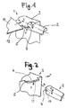
- FIG. 1 shows a simplified representation of an apparatus generally designated 1 for ultrasonic welding.
- the device has as main components a (not shown here) exciters for torsional ultrasonic vibrations excitable sonotrode 2 and an anvil 3.
- the sonotrode 2 whose longitudinal axis extends in the z-direction, is cylindrical at least in the region of the free end.
- the arrow R indicates the torsional vibrations of the sonotrode.
- Of the Anvil has an engaging member 5 which is inserted into a slot 4 in the region of a free end of the sonotrode 2.
- a lateral boundary surface of the slot forms a working surface of the sonotrode.
- the device 1 With the device 1, two plastic films 11 and 12 lying on top of each other can be welded together at the edges.
- the films 11, 12 in the x direction by a Schweissspalt which is formed by a lateral boundary of the slot 4 and the engaging member 5 inserted therein, out and welded under the action of torsional vibrations. In this way, a longitudinal seam is produced at the edge.
- the device is suitable for edge-side welding of two films and in particular of plastic films. Of course, if necessary, three or more sheets could be joined together.
- the device can also be used for continuous scoring of films (scoring, eg as a tear-open aid) or for the complete continuous separation or separation welding of films.
- plastics-coated flat structures made of paper or other laminates are also suitable.
- FIG. 2 is the Sontrode 2 in a waiting position.
- the sonotrode To create the working position (see Fig. 1 ), the sonotrode must be moved by means of (not shown here) drive means of a lifting and lowering device or even manually in the z-direction.
- the engaging member 5 is integrally formed on the anvil 3 and thus configured substantially rigid. Furthermore, it is off FIG. 2 It can be seen that the upper side 6 of the engagement member 5, which is referred to below as the attacking portion, is designed plane and lies on the xy plane.
- the engagement member 5 has a support segment 31 on the front side. This engagement member 5 serves for axial support of the sonotrode 2 in the working position ( Fig. 1 ).
- the support segment 31 is configured by way of example as a conical projection.
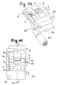
- FIGS. 3 and 4 are sectional views of the device shown. Based FIG. 3 It can be seen that the length of the engagement member 5 is greater than the diameter of the sonotrode 2 and that the engagement member 5 projects beyond the slot 4 on both sides. FIG. 3 further shows that the slot 4 is a continuous, in the x-direction extending longitudinal groove.
- the articles to be processed are impacted approximately perpendicularly (ie, in the y direction) by impacts in the ultrasonic range.
- the device according to the invention uses torsion sonotrodes, the actual loading of the objects to be connected is effected by longitudinal collisions.
- the width of the weld is predetermined by the penetration depth of the engagement member 5 in the slot 4.
- FIG. 4 shows, the groove relative to the end face 15 of the sonotrode 2 in the direction of the longitudinal axis or z-direction deepened.
- the gap 4 is designed as a rectangular cross-section groove, wherein the groove depth is denoted by t and the groove width b.
- the groove depth t is for example between 5 and 30 mm and preferably between 10 and 15 mm
- the groove width b is between 5 and 15 mm and is preferably about 10 mm.
- the gap size of the welding gap is designated by s.
- the slot has two plane-parallel to each other extending side walls 10, 13, wherein the side wall 10 of the films 11, 12 faces and forms a flat work surface 10.
- FIG. 4 shows, formed as a conical projection support segment extends in the axial direction; the apex of the cone is evidently on the z-axis.
- the engagement member 5 is not rigidly connected to the anvil, but resiliently mounted on this.
- Corresponding springs are indicated by 7 and 8. With the springs 7, 8 can be achieved that the film to be welded under the action of a biasing force when passing through the welding gap of a pressing or compressive force is subject. Further, by the floating bearing the springs 7, 8 also cause the engaging member can perform pivotal movements.
- the corresponding pivot axis is identical to the longitudinal axis z.
- the engaging member 5 in the region of the engaging portion 6, a weighing edge 20, to which a wedge surface 21 connects.
- the engaging member 5 For adjusting the width of the welding gap and / or for adjusting the contact pressure, the engaging member 5 by means of a (Adjustment mechanism, not shown here) in the y-direction movably attached to an anvil bracket.
- FIG. 6 shows a side view with the sonotrode 2 and the engaging member 5. It can be seen that the formed work surface 10 is contoured and has a plurality of rib-like, extending in the x-direction projections 16.
- the rib arrangement (or other surface profiling or contour) leads - in contrast to contourless designs - to a welded connection in which not the entire overlap area is welded.
- the rib contour fulfills the function of the energy direction sensor. This allows a targeted introduction of energy into the welding zone.
- FIG. 6 is still a support segment 31 recognizable. In contrast to the previous embodiment (see. Fig.
- the support segment 31 is not assigned to the engagement member, but the slot.
- the support segment 31 is an approximately centrally located in the groove bottom 14 conical projection. Its conical tip is evident on the z-axis and thus forms an advantageous fixed stop or zero point contact, which does not resonate in the ultrasonic welding process.
- FIGS. 7 and 8 an alternative device 1 for ultrasonic welding is shown simplified.
- the sonotrode has no slot.
- the sonotrode 2 has a step-like recess, which forms a work surface designated 10 ( FIG. 8 ).
- the working surface of the sonotrode 3 facing the top of the anvil 3 forms the engaging portion 6.
- the engaging portion 6 forms for the transport of the films 11,12 during ultrasonic welding a sliding surface for the films.
- FIGS. 7 and 8 show, run the engagement section 6 and the working surface 10 in the neutral position parallel to the longitudinal axis z of the sonotrode 2. Between the attack section 10 and work surface 10, the two superimposed films are performed to achieve the welding connection, the films are subjected to ultrasonic vibrations of the sonotrode 2.
- FIG. 9 Another alternative embodiment of a sonotrode is in FIG. 9 shown.
- the sonotrode has a flattened profile extending in the longitudinal direction z, which is formed on a cylindrical base body.
- the profile has a profile side which runs approximately parallel to the longitudinal axis z of the sonotrode 2.
- This profile page is in FIG. 9 designated 10 and forms a work surface for applying objects with ultrasonic vibrations.
- FIG. 10 shows a structural design of an apparatus for ultrasonic welding in the in FIGS. 1 to 4
- the device 1 has a converter 23 which is connected to a torsional oscillator 24.
- the torsional oscillator 24 is in turn connected to the Sontrode 2.
- the anvil 3 has an anvil holder 9, on which the engaging member 5 is attached. Thus, the vibrations can not be transferred to the anvil holder 9, this is comparatively solid.
- the device has an adjusting mechanism with which the position of the engaging member 5 in the slot 4 of the sonotrode 2 can be changed.
- 25 is an adjusting screw for displacing the engaging member in the y direction
- 26 is an adjusting screw for adjusting the angular position of the engaging member in the gap.
- the engagement member 5 is at a slight (and barely recognizable) distance from the working surface 10 of the sonotrode 2 and thus forms an advantageous welding gap (cf. Fig. 12 ).
- the engagement member 5 is supported by means of spring means (not shown here) under a bias against the sonotrode 2 in the y-direction. In the opposite direction to the direction of travel x, ie in an input-side region of the gap between the anvil and sonotrode is expanded, thus forming an insertion gap for facilitating insertion of the films in the welding gap.
- FIG. 12 the welding gap is denoted by s. Between the working surface forming side wall 10 and a received in the slot web portion 17 of the engaging member 5 is the welding gap, which may be about 0.01 mm for common thin films.
- FIG. 12 shows FIG. 12 with 30 and 30 'designated grooves and a cooling channel 28 through which a coolant is passed.
- the web section 17 lies in the in FIG. 12 shown operating position with respect to the longitudinal direction is free or does not come into contact with the bottom 14 of the groove.
- a support segment analogous to FIG. 4 or FIG. 6 is associated with either the engaging member or the bottom of the slot.
- FIG. 13 the sonotrode is shown in a plan view. Out FIG. 13 is clearly visible that the slot 4 is designed as a longitudinal groove with a groove width b.
- the slot 4 has two mutually opposite, approximately parallel side walls 10 and 13, wherein the side wall 10 forms the working surface for applying the objects with ultrasonic vibrations.
- To tune the amplitude or mass balance can be provided in the end face of the sonotrode, for example, by milling operations created recesses or depressions that can stabilize the function of the sonotrode.
- FIGS. 14 and 15 the engagement member 5 is shown.
- This component is configured approximately U-shaped and has two attachment arms 18 and 19 and a web portion 17 connecting them.
- FIG. 14 are provided by bores inputs or outputs 28, 29 and 29 'for cooling ducts can be seen, via which a coolant in the engaging member and can be derived.
- threaded holes for attaching the engaging member to the anvil holder are arranged inside next to the holes designated 29 and 29 '.
- the engaging member 5 may be a one-piece steel member created by drilling and milling operations.
- FIG. 15 shows then that the engaging member 5 on the input side has a straight portion and an adjoining it in the x-direction oblique portion (wedge portion) 21.
- the wedge portion 21 terminates in the edge 20, to which then joins the actual attack section 10 for the welding.
- the preferably central edge 20 preferably serves as a fixed stop point, which does not resonate in the ultrasonic welding process.
- the former portion and the wedge portion 21 provide the insertion gap, over which the objects to be welded on simple manner in the attack section 10 associated welding gap can be inserted. In the insertion, ie up to the edge 20 no welding takes place. From the edge 20, the oscillation amplitude increases continuously.
Abstract
Description
Die Erfindung betrifft eine Vorrichtung und ein Verfahren zur Ultraschallbehandlung gemäss dem Oberbegriff der unabhängigen Ansprüche. Mit einer derartigen Vorrichtung können beispielsweise zwei flächig aufeinander liegende Kunststofffolien randseitig miteinander verbunden werden (Ultraschallschweissen). Auf diese Weise lassen sich beispielsweise Schlauchbeutel zum Verpacken von Verpackungsgut herstellen. Mit der erfindungsgemässen Vorrichtung ist es auch möglich, Kerben (z.B. als Aufreisshilfe) in Folien aufzubringen, wobei hierfür auch nur eine Folie in der Vorrichtung verarbeitet werden könnte. Schliesslich sind auch Trennschweissverfahren von der Erfindung erfasst.The invention relates to a device and a method for ultrasonic treatment according to the preamble of the independent claims. With such a device, for example, two plastic films lying one on top of the other can be connected to one another at the edges (ultrasonic welding). In this way, for example, tubular bags for packaging packaging material can be produced. With the device according to the invention it is also possible to apply notches (for example as a tear-open aid) in foils, it also being possible to process only one foil in the device for this purpose. Finally, separating welding methods are also covered by the invention.
Vorrichtungen zum sogenannten torsionalen Ultraschallschweissen sind seit einer gewissen Zeit bekannt und gebräuchlich. Eine solche Schweissvorrichtung ist beispielsweise aus der
Es ist deshalb eine Aufgabe der vorliegenden Erfindung, die Nachteile des Bekannten zu vermeiden und insbesondere eine Vorrichtung und ein Verfahren der eingangs genannten Art zu schaffen, mit welcher/welchem zwei flächige Gegenstände auf einfache und vorteilhafte Art und Weise miteinander verbunden werden können. Insbesondere soll die Vorrichtung und das Verfahren dazu geeignet sein, zwei oder mehrere Folienteile randseitig miteinander zu verbinden. Die Vorrichtung soll aber auch das Erzeugen von Kerben oder ein Utraschallschweisstrennen von wenigstens einem Gegenstand ermöglichen. Weiter soll sich das Verfahren durch eine effiziente und sichere Betriebsweise auszeichnen.It is therefore an object of the present invention to avoid the disadvantages of the known and in particular to provide a device and a method of the type mentioned, with which / which two flat objects can be connected to each other in a simple and advantageous manner. In particular, the device and the method should be suitable for connecting two or more parts of the foil at the edges. However, the device is also intended to enable the generation of notches or ultrasonic welding separation of at least one object. Furthermore, the process should be characterized by an efficient and safe operation.
Erfindungsgemäss werden diese anderen Aufgaben mit einer Vorrichtung und einem Verfahren gemäss der unabhängigen Patentansprüche gelöst.According to the invention, these other objects are achieved with a device and a method according to the independent patent claims.
Die erfindungsgemässe Vorrichtung weist eine mittels Anregern zu torsionalen Ultraschallschwingungen anregbare Sonotrode auf. Derartige Sonotroden sind dem Fachmann auch unter dem Begriff "Torsionssonotrode" bekannt. Unter torsional wird eine Schwingung der Sonotrode um ihre Längsachse verstanden, d.h. die Sonotrode führt eine torsionale Bewegung um eine Torsionsachse (Längsachse) aus. Die Vorrichtung weist weiter einen der Sonotrode gegenüberliegenden Amboss auf. Zwischen Sonotrode und Amboss ist wenigstens ein Gegenstand zum Erzielen einer Kerbung (Scoring) oder einer Trennung (Trennschweissung) oder zwischen Sonotrode und Amboss sind wenigstens zwei Gegenstände zum Erzielen einer Schweissverbindung durchführbar. Dabei weist der Amboss einen Angriffsabschnitt auf, an dem der wenigstens eine Gegenstand oder die wenigstens zwei Gegenstände entlang führbar ist bzw. sind. Die Sonotrode weist eine Arbeitsfläche zum Beaufschlagen des wenigstens einen Gegenstands mit Ultraschall-Schwingungen auf, wobei der Angriffsabschnitt und/oder die Arbeitsfläche wenigstens in einer Neutralstellung wenigstens abschnittsweise etwa parallel zur Längsachse der Sonotrode verlaufen. Die Gegenstände können kontinuierlich zwischen dem Angriffsabschnitt und der Arbeitsfläche durchgeführt werden. Die Arbeitsfläche führt Schwingungen aus, die etwa senkrecht zu ihr verlaufen.The device according to the invention has a sonotrode which can be excited by means of exciters for torsional ultrasonic vibrations. Such sonotrodes are known to the person skilled in the art under the term "torsion sonotrode". By torsional is meant a vibration of the sonotrode about its longitudinal axis, ie the sonotrode performs a torsional movement about a torsion axis (longitudinal axis). The device further comprises an anvil opposite the sonotrode. Between the sonotrode and the anvil is at least one object for achieving a scoring or a separation (separation welding) or between the sonotrode and the anvil at least two objects to achieve a welded connection feasible. In this case, the anvil has an engaging portion, on which the at least one object or the at least two objects is or can be guided along. The sonotrode has a working surface for acting on the at least one object with ultrasonic vibrations, wherein the engaging portion and / or the working surface extend at least in sections approximately parallel to the longitudinal axis of the sonotrode, at least in a neutral position. The articles may be continuously carried between the engaging section and the work surface. The work surface executes vibrations that are approximately perpendicular to it.
In einer vorteilhaften Ausführungsform kann die Sonotrode wenigstens einen Schlitz aufweisen, in den ein Eingriffsglied des Ambosses einführbar oder eingeführt ist, so dass ein Spalt für den wenigstens einen Gegenstand gebildet wird. Für den vorgängig genannten Fall, bei dem zwei Gegenstände zum Erzielen einer Schweissverbindung zwischen Sonotrode und Amboss durchgeführt werden, wird für den Spalt der Begriff "Schweissspalt" verwendet. Durch den Schweissspalt zwischen Sonotrode und Amboss können zum Beispiel zwei flächig aufeinander liegende Folien (-teile) randseitig durch den Schweissspalt geführt und so verschweisst werden. Mit dieser Vorrichtung lassen sich auf einfache Art und Weise kontinuierliche Längsschweissnähte erzeugen. Selbstverständlich ist mit dieser Vorrichtung aber auch eine diskontinuierliche Betriebsweise möglich, bei der einzelne Schweissnähte durch unverschweisste Abschnitte unterbrochen sind. Mit der Vorrichtung können vorteilhaft Kunststofffolien oder auch Metallfolien (z.B. Aluminiumfolien) sowie beschichtete Folien verarbeitet werden. die Folien können mit Fördermitteln durch den Schweissspalt gezogen oder auf andere Weise bewegt werden. Dieses Führen der Folienränder durch den zwischen Eingriffsglied und Arbeitsfläche gebildeten Schweissspalt gewährleistet einen sicheren und effizienten Betrieb während einem Schweissvorgang. Grundsätzlich eignet sich die Vorrichtung zum Verbinden verschiedener Arten von Gegenständen. Beispielsweise könnte mit der Vorrichtung auch ein folienartiger Deckel an einen mit einem Kragen versehenen Behälter angeschweisst werden. Im letztgenannten Anwendungsfall müsste der Kragen durch die Anordnung mit dem Schweissspalt entlang des Kragens geführt werden. Neben den bereits erwähnten Vorteilen kann die Vorrichtung auch auf günstige Weise in einer automatischen Produktionslinie eingefügt und verwendet werden. Wenn der Anfang des eigentlichen Schweissspalts (z.B. gebildet durch die vorgängig erwähnten Wiegekante) etwa mittig, d.h. durch oder benachbart zur Sonotrodenachse verläuft, ist die Amplitude in einem zentralen Bereich null oder jedenfalls sehr gering. Gegen den Rand der Sonotrode erhöht sich die Amplitude. Damit kann eine kontinuierliche Zunahme erzielt werden.In an advantageous embodiment, the sonotrode may have at least one slot into which an engagement member of the anvil is inserted or inserted, so that a gap for the at least one object is formed. For the aforementioned case, in which two objects are carried out to achieve a welding connection between sonotrode and anvil, the term "welding gap" is used for the gap. By means of the welding gap between the sonotrode and the anvil, for example, two sheets (parts) which lie one on top of the other can be guided on the edge side through the welding gap and thus welded. With this device can be produced in a simple manner continuous longitudinal welds. Of course, with this device but also a discontinuous mode of operation is possible in which individual welds are interrupted by unshielded sections. With the device advantageously plastic films or metal foils (eg aluminum foils) and coated films can be processed. the films can be pulled through conveyors through the welding gap or moved in some other way. This guiding of the film edges by the welding gap formed between the engaging member and the working surface ensures safe and efficient operation during a welding operation. Basically, the device is suitable for connecting different types of objects. For example, with the device, a film-like lid could be welded to a container provided with a collar. In the latter application, the collar would have to be guided by the arrangement with the welding gap along the collar. In addition to the advantages already mentioned, the device can also be conveniently inserted and used in an automated production line. If the beginning of the actual welding gap (eg formed by the previously mentioned weighing edge) runs approximately in the middle, ie through or adjacent to the sonotrode axis, the amplitude in a central region is zero or at least very small. Towards the edge of the sonotrode, the amplitude increases. Thus, a continuous increase can be achieved.
Die Arbeitsfläche kann durch eine entsprechende Ausgestaltung wenigstens des dem Amboss zugewandten stirnseitigen Endes der Sonotrode geschaffen werden. Beispielsweise kann an der Stirnseite der Sonotrode ein sich in axialer Richtung erstreckende Zunge (beispielsweise ein sich in axialer Richtung erstreckendes abgeflachtes Profil) angeformt oder auf andere Art und Weise angebracht sein. Zum Vorgeben der Arbeitsfläche kommt auch eine stufenartige Aussparung im Bereich der Stirnseite der Sonotrode in Frage. Es wäre sogar auch denkbar, dass - anstatt der Sonotrode - der Amboss wenigstens einen Schlitz aufweisen könnte. Das Eingriffsglied wäre in diesem Fall somit der Sonotrode zugeordnet. In diesem Fall könnte das der Sonotrode zugeordnete Eingriffsglied als sich in Richtung der Längsachse erstreckende, beispielsweise zapfenförmige Zunge ausgestaltet sein. Das Vorsehen eines oder mehrer Schlitzes in der Sonotrode ist also für bestimmte Anwendungsfälle nicht zwingend erforderlich.The work surface can be created by a corresponding design of at least the anvil facing the front end of the sonotrode. For example, a tongue extending in the axial direction (for example, a flattened profile extending in the axial direction) may be formed on the end face of the sonotrode or attached in another manner. To specify the work surface is also a step-like recess in the front end of the sonotrode in question. It would even be conceivable that - instead of the sonotrode - the anvil could have at least one slot. The engagement member would thus be assigned to the sonotrode in this case. In this case, the engagement member assigned to the sonotrode could be designed as a tongue, which extends in the direction of the longitudinal axis and is for example a peg-shaped tongue. The provision of one or more slots in the sonotrode is therefore not absolutely necessary for certain applications.
Theoretisch ist es sodann auch denkbar, dass die Vorrichtung mit mehreren parallel verlaufenden oder sogar sich kreuzenden Schlitzen versehen sein könnte. Bevorzugt weist die Sonotrode aber nur einen Schlitz auf.Theoretically, it is then also conceivable that the device could be provided with a plurality of parallel or even intersecting slots. Preferably, however, the sonotrode has only one slot.
In einer ersten Ausführungsform kann der Schlitz eine sich in einer Nutrichtung erstreckende Nut sein, wobei die Nutrichtung quer, vorzugsweise rechtwinklig zur Längsachse der Sonotrode verlaufen kann und/oder Seitenwände aufweist, die parallel zur Längsachse verlaufen und die Arbeitsfläche bilden. Die Nutrichtung gibt im Übrigen auch die Fortbewegungsrichtung der Gegenstände im Schweissbetrieb vor. Vorteilhaft ist der Schlitz als durchlaufende Nut ausgestaltet, wobei der Nutquerschnitt vorzugsweise rechteckig sein kann. Somit können zwei aufeinander gelegte Kunststofffolien randseitig besonders einfach in Nutrichtung durch den Schlitz bzw. den Schweissspalt gezogen werden.In a first embodiment, the slot may be a groove extending in a groove direction, wherein the groove direction may extend transversely, preferably at right angles to the longitudinal axis of the sonotrode and / or has side walls which are parallel to the longitudinal axis and form the working surface. Incidentally, the groove direction also indicates the direction of movement of the objects in welding operation. Advantageously, the slot is designed as a continuous groove, wherein the groove cross-section may preferably be rectangular. Thus, two plastic films placed on top of each other can be drawn particularly easily in the groove direction through the slot or the welding gap.
Besonders vorteilhaft kann es sein, wenn der Schlitz eine Nut ist, der gegenüber einer Stirnfläche in Richtung der Längsachse der Sonotrode vertieft ist. Diese Vertiefung legt die Nuttiefe fest. Für die erstgenannte Variante, bei der der Schlitz der Sonotrode und das Eingriffsglied dem Amboss zugeordnet ist, kann die dem Amboss zugewandte Seite der Sonotrode die genannte Stirnfläche bilden.It may be particularly advantageous if the slot is a groove which is recessed in relation to an end face in the direction of the longitudinal axis of the sonotrode. This depression determines the groove depth. For the first-mentioned variant, in which the slot of the sonotrode and the engagement member is associated with the anvil, the anvil-facing side of the sonotrode may form said end face.
Die Nuttiefe des Schlitzes legt eine Obergrenze für Schweissnahtbreite fest. Die Breite der Schweissnaht kann etwa die Eindringtiefe des Eingriffglieds in den Schlitz sein. Der Schlitz kann eine Nuttiefe aufweisen, die zwischen 5 und 30 mm und bevorzugt zwischen 10 und 15 mm liegt. Die Nutbreite kann zwischen 5 und 15 mm liegen und bevorzugt bei einem Sonotrodendurchmesser von 40 - 50mm etwa 10 mm betragen. Das zum Schlitz korrespondierende Eingriffsglied kann wenigstens in Bezug auf die Breitenausdehnung ein Untermass aufweisen. Die Schweissspaltbreite hängt vom Folienmaterial und der Foliendicke ab. Die Breite des Schweissspaltes (Spaltmass) variiert für gängige Foliendicken (z.B. 20-150 µm).The groove depth of the slot defines an upper limit for weld width. The width of the weld may be about the penetration depth of the engagement member in the slot. The slot may have a groove depth which is between 5 and 30 mm and preferably between 10 and 15 mm. The groove width can be between 5 and 15 mm and preferably be about 10 mm with a sonotrode diameter of 40-50 mm. The engagement member corresponding to the slot may have an undersize at least in relation to the width extent. The welding gap width depends on the film material and the film thickness. The width of the Weld gap (gap dimension) varies for common film thicknesses (eg 20-150 μm).
In einer weiteren Ausführungsform kann der Schlitz zwei einander gegenüberliegende Seitenwände aufweisen, wobei eine der Seitenwände eine Arbeitsfläche zum Beaufschlagen der wenigstens eine Gegenstand mit Ultraschallschwingungen bilden kann. Dabei kann der Amboss oder die Sonotrode einen der Arbeitsfläche zugewandten Angriffsabschnitt aufweisen, wobei zwischen Arbeitsfläche und Angriffsabschnitt der Schweissspalt liegt. Der Angriffsabschnitt kann eine Führungsfläche für ein Folienteil bilden. Während einem Schweissvorgang können die Gegenstände auf der einen Seite an dieser Führungsfläche in flächiger Auflage entlang gleiten und auf der anderen Seite können die Gegenstände von der Arbeitsfläche mit Ultraschallschwingungen beaufschlagt werden.In another embodiment, the slot may have two opposing side walls, wherein one of the side walls may form a working surface for subjecting the at least one article to ultrasonic vibrations. In this case, the anvil or the sonotrode may have a working surface facing the attack portion, wherein between working surface and attacking portion of the welding gap. The engagement portion may form a guide surface for a film part. During a welding process, the objects can slide on one side of this guide surface in a flat support along and on the other side, the objects can be acted upon by the working surface with ultrasonic vibrations.
Das Eingriffsglied oder die Sonotrode kann mittels Federmitteln zum Erzeugen eines Anpressdrucks unter einer Vorspannung gegen eine Arbeitsfläche des Schlitzes abstützbar oder abgestützt sein. Mit dieser Federanordnung ergibt sich eine vorteilhafte Spaltkompensation. Damit können zum Beispiel plötzlich auftretende Dickstellen (z.B. Foliensplice, Falten usw.) beim Durchführen des wenigstens einen Gegenstands kompensiert werden. Insbesondere können dadurch beispielsweise Kunststofffolien oder andere Folienteile sowie sehr dünne Gegenstände wie etwa Membranen vor Beschädigungen auf einfache Art und Weise geschützt werden. Auch erlaubt diese Anordnung das Verbinden von aufeinanderfolgenden überlappenden Folienbahnen (sogenanntes Splicing).The engagement member or the sonotrode can be supported or supported by spring means for generating a contact pressure under a bias against a working surface of the slot. With this spring arrangement results in an advantageous gap compensation. Thus, for example, suddenly occurring thick spots (e.g., foil splice, wrinkles, etc.) may be compensated for in performing the at least one article. In particular, this allows, for example, plastic films or other film parts as well as very thin objects such as membranes to be protected from damage in a simple manner. This arrangement also allows the joining of successive overlapping film webs (so-called splicing).
Zum Einstellen der Breite des Schweissspalts oder zum Einstellen des durch die Federmittel erzeugten Anpressdrucks kann das Eingriffsglied oder ein dem Spalt zugeordnetes Teil des Ambosses über einen Verstellmechanismus bewegbar an einer Ambosshalterung befestigt sein. Dadurch lässt sich die Vorrichtung auf einfache Art und Weise an unterschiedliche Dicken von zu verschweissenden Gegenständen anpassen. Zusätzlich oder alternativ kann die Vorrichtung über einen Verstellmechanismus verfügen, mit dessen Hilfe die Winkellage des Eingriffsglieds in Bezug auf den Spalt verstellbar ist. Mit der Winkellagenverstellung kann betreffend die Neutralstellung je nach Wunsch eine exakte Planparallelität von Arbeitsfläche und Angriffsabschnitt oder ein sich öffnender oder sich verengender Schweissspalt eingestellt werden.For adjusting the width of the welding gap or for adjusting the contact pressure generated by the spring means, the engaging member or a part of the anvil associated with the gap can be moved via an adjusting mechanism to an anvil holder be attached. As a result, the device can be adapted in a simple manner to different thicknesses of objects to be welded. Additionally or alternatively, the device may have an adjusting mechanism with the help of which the angular position of the engaging member is adjustable with respect to the gap. With the angular position adjustment can be adjusted with respect to the neutral position as desired, an exact parallelism of working surface and attack section or an opening or narrowing welding gap.
Das Eingriffsglied des Ambosses oder ein dem Spalt zugeordnetes Teil des Ambosses kann um eine Schwenkachse schwenkbar (oder kippbar) an einer Ambosshalterung gelagert sein. Die Schwenkachse kann dabei achsparallel zur Längsachse der Sonotrode verlaufen. Die Schwenkachse kann beispielsweise durch einen Achsenzapfen und ein komplementäres Drehlager vorgegeben sein. Selbstverständlich ist es aber auch denkbar, dass die Vorrichtung über eine imaginäre Schwenkachse verfügen könnte. Beispielsweise kann das Eingriffsglied nur an zwei seitlich angeordneten Federn an der Ambosshalterung abgestützt sein, wodurch ebenfalls eine Schwenk- oder Kippbewegung des Eingriffsglieds möglich wäre.The engagement member of the anvil or a part of the anvil associated with the gap may be pivotally (or tiltably) mounted on an anvil support about a pivot axis. The pivot axis can thereby run axially parallel to the longitudinal axis of the sonotrode. The pivot axis may be predetermined, for example, by an axle journal and a complementary pivot bearing. Of course, it is also conceivable that the device could have an imaginary pivot axis. For example, the engagement member may be supported only on two laterally disposed springs on the anvil holder, whereby also a pivoting or tilting movement of the engagement member would be possible.
Vorteile können sich ergeben, wenn das Eingriffsglied etwa U-förmig oder bügelförmig ausgestaltet ist. Dabei kann das Eingriffsglied zur Bildung der U- oder Bügelform zwei Befestigungsarme und einen diese verbindenden Stegabschnitt aufweisen. Der Stegabschnitt kann dabei im Schlitz aufgenommen oder aufnehmbar sein. Das Eingriffsglied kann derart positioniert bzw. ausgerichtet sein, dass das U auf einer Ebene liegt, deren Flächennormale parallel zur Längsachse verläuft.Benefits may arise when the engagement member is configured approximately U-shaped or bow-shaped. In this case, the engagement member for forming the U-shape or bow have two attachment arms and a web portion connecting them. The web section can be received or receivable in the slot. The engagement member may be positioned such that the U lies on a plane whose surface normal is parallel to the longitudinal axis.
Besonders vorteilhaft kann es sein, wenn im Verbindungsbereich zwischen einer Ambosshalterung und den Befestigungsarmen jeweils ein Federelement, beispielsweise eine Schraubendruckfeder zur federnden Abstützung vorgesehen ist.It may be particularly advantageous if in the connection region between an anvil holder and the mounting arms respectively a spring element, for example, a helical compression spring is provided for resilient support.
Eine vorteilhafte Schweissung lässt sich erreichen, wenn das Eingriffsglied in Bezug auf die Nutrichtung länger als der Spalt ist und vorzugsweise beidseitig den Spalt überragt. Wenn beispielsweise das Eingriffsglied U-förmig oder bügelförmig ausgestaltet ist, können die Befestigungsarme jeweils an den den Spalt überragenden Teil des Stegabschnitts angeformt sein.An advantageous welding can be achieved if the engagement member is longer than the gap with respect to the groove direction and preferably projects beyond the gap on both sides. If, for example, the engagement member is U-shaped or bow-shaped, the attachment arms can each be molded onto the part of the web section projecting beyond the gap.
Das Eingriffsglied enthaltend die beiden Befestigungsarme und den Stegabschnitt kann als einstückiger Körper aus Metall (z.B. Stahl) ausgestaltet sein. Derartige einstückige Bauteile lassen sich durch Fräsoperationen auf einfache Art und Weise fertigen.The engagement member including the two attachment arms and the land portion may be configured as a one-piece body of metal (e.g., steel). Such one-piece components can be manufactured by milling operations in a simple manner.
Das Eingriffsglied kann im Bereich des Eingriffabschnitts eine Kante aufweisen. Die Kante kann zum Beispiel eine Wiegekante sein, an die eine Keilfläche anschliesst. Die Kante kann sich in der Mitte des Eingriffsglieds befinden. Die Kante kann weiterhin derart in der Vorrichtung positioniert sein, dass sie in Bezug auf die Nutrichtung etwa in der Mitte des Schlitzes liegt.The engagement member may have an edge in the region of the engagement portion. The edge may, for example, be a cradle edge followed by a wedge surface. The edge can be in the middle of the engagement member. The edge may also be positioned in the device such that it lies approximately in the middle of the slot with respect to the groove direction.
Theoretisch ist es denkbar, dass der Angriffsabschnitt in einer Draufsicht konvex gekrümmt sein kann.Theoretically, it is conceivable that the engagement portion may be convexly curved in a plan view.
Für bestimmte Anwendungsfälle kann es vorteilhaft sein, wenn die durch eine Seitenwand gebildete Arbeitsfläche plan ist.For certain applications, it may be advantageous if the work surface formed by a side wall is flat.
Vorteilhaft kann es aber auch sein, wenn die durch eine Seitenwand gebildete Arbeitsfläche konturiert ist. Beispielsweise könnte die Seitenwand mit einer Mehrzahl von zum Beispiel etwa punktförmigen Vorsprüngen versehen sein, wodurch die beiden Gegenstände punktuell mit Ultraschallschwingungen beaufschlagt werden können.But it can also be advantageous if the working surface formed by a side wall is contoured. For example, the side wall could be provided with a plurality of, for example, approximately point-shaped projections, whereby the two objects can be applied selectively with ultrasonic vibrations.
Besonders vorteilhaft kann es aber sein, wenn die Kontur durch wenigstens einen rippenartigen Vorsprung gebildet wird. Bevorzugt weist die Kontur dabei mehrere rippenartige Vorsprünge auf. Die Kontur kann in Nutrichtung verlaufende Längsrippen aufweisen.But it may be particularly advantageous if the contour is formed by at least one rib-like projection. The contour preferably has a plurality of rib-like projections. The contour may have longitudinal ribs extending in the groove direction.
In einer weiteren Ausführungsform kann das Eingriffsglied oder der Schlitz zum axialen Abstützen der Sonotrode ein Stützsegment aufweisen. Das Stützsegment kann sich in Richtung der Längsachse erstrecken. Das Stützsegment kann dabei wenigstens in einer Arbeitsposition derart positioniert sein, dass das Stützsegment einen Angriffspunkt definiert, der vorzugsweise in der Längsachse der Sonotrode liegt. Ein solcher mittiger Angriffspunkt ergibt einen Festanschlag oder Nullpunktkontakt, der im Ultraschweissvorgang nicht mitschwingt. Das Stützsegment kann beispielsweise ein am Boden des Schlitzes angeformter oder auf andere Weise befestigter kegelförmiger Vorsprung sein. Durch die Kegelspitze ist ein vorteilhafter punktueller Anschlag gewährleistet. Selbstverständlich sich neben der Kegelform auch andere Formgebungen für den Vorsprung denkbar.In a further embodiment, the engagement member or the slot for axially supporting the sonotrode may have a support segment. The support segment may extend in the direction of the longitudinal axis. The support segment can be positioned at least in a working position such that the support segment defines a point of application, which preferably lies in the longitudinal axis of the sonotrode. Such a center point results in a fixed stop or zero point contact, which does not resonate in Ultraschallweissvorgang. The support segment may be, for example, a cone-shaped projection formed on the bottom of the slot or otherwise secured. By the cone tip a favorable punctual stop is guaranteed. Of course, in addition to the conical shape, other shapes for the projection conceivable.
Ein weiterer Aspekt der Erfindung betrifft ein Verfahren zum Ultraschallschweissen von wenigstens zwei vorzugsweise flächigen Gegenständen. Das Verfahren kann auf vorteilhafte Art und Weise auf der vorgängig beschriebenen Vorrichtung ausgeführt werden. Das Verfahren zeichnet sich dadurch aus, dass beispielsweise zum Erzeugen einer Längsnaht die wenigstens zwei Gegenstände durch einen zwischen einer Arbeitsfläche einer Torsionssonotrode und einem Angriffsabschnitt gebildeten Schweissspalt geführt werden. Die Arbeitsfläche verläuft etwa parallel zur Achse der Torsionssonotrode. Die Beaufschlagung mit Ultraschallschwingungen beim vorliegenden Ultraschallschweiss-Verfahren erfolgt etwa senkrecht zu den Gegenständen mittels einer torsional schwingenden Sonotrode, die über wenigstens einen Schlitz verfügt.Another aspect of the invention relates to a method for ultrasonic welding of at least two preferably flat objects. The method can be carried out in an advantageous manner on the device described above. The method is characterized in that, for example, to produce a longitudinal seam, the at least two objects are guided through a welding gap formed between a working surface of a torsion sonotrode and an engaging portion. The working surface runs approximately parallel to the axis of the torsion sonotrode. The application of ultrasonic vibrations in the present ultrasonic welding method is approximately perpendicular to the objects by means of a torsionally vibrating sonotrode, which has at least one slot.
Weitere Einzelmerkmale und Vorteile der Erfindung ergeben sich aus der nachfolgenden Beschreibung der Ausführungsbeispiele und aus den Zeichnungen. Es zeigen:
- Figur 1
- eine perspektivische, stark vereinfachte Darstellung einer erfindungsgemässen Vorrichtung zum Ultraschall- schweissen in einer Arbeitsstellung,
Figur 2- die Vorrichtung gemäss
Figur 1 mit einer Sonotrode in einer Ruhestellung, Figur 3- einen Querschnitt durch die Vorrichtung gemäss
Figur 1 (Schnittebene x-y), Figur 4- eine weitere Schnittdarstellung der Vorrichtung (Schnittebene y-z),
Figur 5- eine Draufsicht auf eine Sonotrode und eine in deren Schlitz angeführtes Eingriffsglied einer Vorrichtung gemäss einem zweiten Ausführungsbeispiel,
Figur 6- eine Querschnittsdarstellung der Anordnung gemäss
Figur 5 , - Figur 7
- eine perspektivische, stark vereinfachte Darstellung einer erfindungsgemässen Vorrichtung gemäss einem al- ternativen Ausführungsbeispiel,
- Figur 8
- eine Seitenansicht der Vorrichtung gemäss
Figur 7 , Figur 9- eine perspektivische Darstellung einer Sonotrode für ein weiteres Ausführungsbeispiel einer Vorrichtung zum Ultraschallschweissen,
Figur 10- eine perspektivische Darstellung der Vorrichtung gemäss einem weiteren Ausführungsbeispiel,
Figur 11- eine Draufsicht auf die
Vorrichtung gemäss Figur 10 , Figur 12- einen Ausschnitt eines Querschnitts durch die Vorrich-
tung gemäss Figur 10 in einer vergrösserten Darstel- lung, Figur 13- eine Draufsicht auf eine Sonotrode der Vorrichtung ge-
mäss Figur 10 , Figur 14- eine perspektivische Darstellung eines Eingriffsglieds der Vorrichtung gemäss
Figur 10 , und Figur 15- eine Draufsicht auf das Eingriffsglied.
- FIG. 1
- a perspective, greatly simplified representation of an inventive device for ultrasonic welding in a working position,
- FIG. 2
- the device according to
FIG. 1 with a sonotrode in a rest position, - FIG. 3
- a cross section through the device according to
FIG. 1 (Sectional plane xy), - FIG. 4
- a further sectional view of the device (section plane yz),
- FIG. 5
- a top view of a sonotrode and an insert in the slot engaging member of a device according to a second embodiment,
- FIG. 6
- a cross-sectional view of the arrangement according to
FIG. 5 . - FIG. 7
- a perspective, greatly simplified representation of an inventive device according to an alternative embodiment,
- FIG. 8
- a side view of the device according to
FIG. 7 . - FIG. 9
- a perspective view of a sonotrode for a further embodiment of an apparatus for ultrasonic welding,
- FIG. 10
- a perspective view of the device according to another embodiment,
- FIG. 11
- a plan view of the device according to
FIG. 10 . - FIG. 12
- a section of a cross section through the device according to
FIG. 10 in an enlarged view, - FIG. 13
- a plan view of a sonotrode of the device according to GE
FIG. 10 . - FIG. 14
- a perspective view of an engaging member of the device according to
FIG. 10 , and - FIG. 15
- a plan view of the engaging member.
Mit der Vorrichtung 1 können zwei aufeinander liegende Kunststofffolien 11 und 12 randseitig miteinander verschweisst werden. Hierzu werden die Folien 11, 12 in x-Richtung durch einen Schweissspalt, der durch eine seitliche Begrenzung des Schlitzes 4 und das darin eingeführte Eingriffsglied 5 gebildet wird, geführt und unter Einwirkung von torsionalen Schwingungen verschweisst. Auf diese Weise entsteht randseitig eine Längsnaht. Die Vorrichtung eignet sich zum randseitigen Verschweissen zweier Folien und insbesondere von Kunststofffolien. Selbstverständlich könnten bei Bedarf drei oder mehrere Folien miteinander verbunden werden. Außerdem ist mit der Vorrichtung auch das kontinuierliche Kerben von Folien (Scoring, z. B. als Aufreisshilfe) oder das vollständige kontinuierliche Trennen oder Trennschweißen von Folien möglich. Anstatt von Kunststoffen ist weiter die Verarbeitung anderer Materialien denkbar, wobei vor allem Folien aus Metall in Frage kommen. Zum Verschweissen mit der nachfolgend näher beschriebnen Vorrichtung eignen sich sodann auch mit Kunststoff beschichtete flächige Gebilde aus Papier oder andere Laminate.With the device 1, two
In
In den
Wie aus
Im Unterschied zum vorgehenden Ausführungsbeispiel ist in
Zum Einstellen der Breite des Schweissspalts und/oder zum Einstellen des Anpressdrucks ist das Eingriffsglied 5 mittels einem (hier nicht dargestellten Verstellmechanismus) in y-Richtung bewegbar an einer Ambosshalterung befestigt.For adjusting the width of the welding gap and / or for adjusting the contact pressure, the engaging
In
In den
Eine weitere alternative Ausgestaltung einer Sonotrode ist in
Anhand der Draufsicht gemäss
In
In
In den
Claims (15)
mit einer Sonotrode (2) und einem der Sonotrode gegenüberliegenden Amboss (3), wobei die Sonotrode mittels Anregern (23, 24) zu torsionalen Ultraschallschwingungen anregbar ist, dadurch gekennzeichnet, dass zwischen Sonotrode (2) und Amboss (3) der wenigstens eine Gegenstand (11, 12) zum Erzielen einer Schweissverbindung, einer Kerbung oder einer Trennung durchführbar sind, wobei der Amboss (3) einen Angriffsabschnitt (6) aufweist, an dem der wenigstens eine Gegenstand (11, 12) entlang führbar ist und wobei die Sonotrode (2) eine Arbeitsfläche (10) zum Beaufschlagen des wenigstens einen Gegenstands mit Ultraschall-Schwingungen aufweist, wobei der Angriffsabschnitt (6) und/oder die Arbeitsfläche (10) wenigstens in einer Neutralstellung wenigstens abschnittsweise etwa parallel zur Längsachse (z) der Sonotrode verlaufen.Apparatus for ultrasonic treatment, in particular for ultrasonic welding of at least two preferably flat objects (11, 12), in particular of plastic films, or for ultrasonic notching or separating welding of at least one preferably flat object,
with a sonotrode (2) and an anvil (3) opposite the sonotrode, the sonotrode being excitable by means of exciters (23, 24) for torsional ultrasonic oscillations, characterized in that between sonotrode (2) and anvil (3) the at least one object (11, 12) for achieving a welded connection, a notch or a separation, wherein the anvil (3) has an engaging portion (6), along which the at least one object (11, 12) is guidable and wherein the sonotrode ( 2) has a working surface (10) for acting on the at least one object with ultrasonic oscillations, the attacking section (6) and / or the working surface (10) extending at least partially in a neutral position approximately parallel to the longitudinal axis (z) of the sonotrode.
Priority Applications (2)
| Application Number | Priority Date | Filing Date | Title |
|---|---|---|---|
| EP09162197A EP2261008A1 (en) | 2009-06-08 | 2009-06-08 | Device and method for ultrasound treatment |
| US12/796,306 US20100307660A1 (en) | 2009-06-08 | 2010-06-08 | Device and Method for Ultrasonic Treatment |
Applications Claiming Priority (1)
| Application Number | Priority Date | Filing Date | Title |
|---|---|---|---|
| EP09162197A EP2261008A1 (en) | 2009-06-08 | 2009-06-08 | Device and method for ultrasound treatment |
Publications (1)
| Publication Number | Publication Date |
|---|---|
| EP2261008A1 true EP2261008A1 (en) | 2010-12-15 |
Family
ID=41258260
Family Applications (1)
| Application Number | Title | Priority Date | Filing Date |
|---|---|---|---|
| EP09162197A Withdrawn EP2261008A1 (en) | 2009-06-08 | 2009-06-08 | Device and method for ultrasound treatment |
Country Status (2)
| Country | Link |
|---|---|
| US (1) | US20100307660A1 (en) |
| EP (1) | EP2261008A1 (en) |
Cited By (2)
| Publication number | Priority date | Publication date | Assignee | Title |
|---|---|---|---|---|
| RU2537681C2 (en) * | 2013-05-07 | 2015-01-10 | Федеральное государственное бюджетное образовательное учреждение высшего профессионального образования "Омский государственный технический университет" | Device for seam ultrasound welding of polymers |
| WO2017000998A1 (en) | 2015-06-30 | 2017-01-05 | Telsonic Holding Ag | Device for the welding of components by way of ultrasound by torsional vibrations |
Families Citing this family (1)
| Publication number | Priority date | Publication date | Assignee | Title |
|---|---|---|---|---|
| DE102012111734A1 (en) * | 2012-12-03 | 2014-06-05 | Schunk Sonosystems Gmbh | Ultrasonic welding device and method for welding electrical conductors |
Citations (3)
| Publication number | Priority date | Publication date | Assignee | Title |
|---|---|---|---|---|
| JPH0629357A (en) | 1992-06-26 | 1994-02-04 | Suzuki Motor Corp | Ultrasonic welding apparatus |
| EP1410988A1 (en) | 2001-03-12 | 2004-04-21 | Shikoku Kakoki Co., Ltd. | Ultrasonic wave sealing method for container |
| EP1930148A1 (en) * | 2006-12-07 | 2008-06-11 | Telsonic Holding AG | Use of a device for torsional, ultrasonic welding |
Family Cites Families (1)
| Publication number | Priority date | Publication date | Assignee | Title |
|---|---|---|---|---|
| WO1993008978A1 (en) * | 1991-10-28 | 1993-05-13 | Abbott Laboratories | An ultrasonically welded plastic ribbon and apparatus and process for forming same |
-
2009
- 2009-06-08 EP EP09162197A patent/EP2261008A1/en not_active Withdrawn
-
2010
- 2010-06-08 US US12/796,306 patent/US20100307660A1/en not_active Abandoned
Patent Citations (3)
| Publication number | Priority date | Publication date | Assignee | Title |
|---|---|---|---|---|
| JPH0629357A (en) | 1992-06-26 | 1994-02-04 | Suzuki Motor Corp | Ultrasonic welding apparatus |
| EP1410988A1 (en) | 2001-03-12 | 2004-04-21 | Shikoku Kakoki Co., Ltd. | Ultrasonic wave sealing method for container |
| EP1930148A1 (en) * | 2006-12-07 | 2008-06-11 | Telsonic Holding AG | Use of a device for torsional, ultrasonic welding |
Cited By (4)
| Publication number | Priority date | Publication date | Assignee | Title |
|---|---|---|---|---|
| RU2537681C2 (en) * | 2013-05-07 | 2015-01-10 | Федеральное государственное бюджетное образовательное учреждение высшего профессионального образования "Омский государственный технический университет" | Device for seam ultrasound welding of polymers |
| WO2017000998A1 (en) | 2015-06-30 | 2017-01-05 | Telsonic Holding Ag | Device for the welding of components by way of ultrasound by torsional vibrations |
| US10532424B2 (en) | 2015-06-30 | 2020-01-14 | Telsonic Holding Ag | Device for welding components by means of ultrasound |
| US11247294B2 (en) | 2015-06-30 | 2022-02-15 | Telsonic Holding Ag | Device for welding components by means of ultrasound |
Also Published As
| Publication number | Publication date |
|---|---|
| US20100307660A1 (en) | 2010-12-09 |
Similar Documents
| Publication | Publication Date | Title |
|---|---|---|
| EP1849569B1 (en) | Device for machining workpieces using ultrasound and method for operating such a device | |
| EP2219848B1 (en) | Sonotrode with u gap | |
| EP1140474B1 (en) | Method for keeping constant the mean gap width between a sonotrode of an ultrasound system and a tool configured as a counter surface and forming part of an ultrasonic cutting device | |
| DE102009027021B3 (en) | Ultrasound welding device for welding two components, comprises a rod-shaped first sonotrode for generating longitudinal waves coupled at its first end on a first converter and at its second end on a second converter | |
| EP3124803B1 (en) | Punch rivet device | |
| EP2945793B1 (en) | Ultrasound welding device comprising vibration-decoupled counter tool | |
| EP3117923A1 (en) | Method for connecting at least two components by means of a self-piercing rivet device and manufacturing equipment | |
| EP2261008A1 (en) | Device and method for ultrasound treatment | |
| EP3124133B1 (en) | Self-piercing rivet device with a die and use of such die | |
| DE102006020429A1 (en) | Ultrasonic guillotine has fixed anvil surface and cutting tool linked to energy source | |
| EP2564969B1 (en) | Friction stir welding method for connecting two panel-shaped workpieces | |
| EP1354693B1 (en) | Process for ultrasonic welding of thin walled parts | |
| EP3034276B1 (en) | Component with firmly bonded connection and a joining method | |
| EP3120950A1 (en) | Transfer element for a self-piercing rivet device, self-piercing rivet device, production device and method for determining a vibration characteristic | |
| DE19809581A1 (en) | Working metal between hammer and support | |
| DE102021131399A1 (en) | METHOD AND DEVICE FOR APPLYING AN ACTIVE JOINING FORCE DURING LASER WELDING OF OVERLAPPING WORKPIECES | |
| EP3552729B1 (en) | Punch riveting device | |
| DE102005010269A1 (en) | Method of producing a component from two elements having a curved and flat surface respectively as in motor vehicle production directs laser beam at the contact region between the two surfaces | |
| EP3592498B1 (en) | Ultrasonic welding apparatus and ultrasonic welding method | |
| EP1996365B1 (en) | Method and device for welding elements made of metallic materials | |
| EP1857587B1 (en) | Method for manufacturing a hollow body of a machine for manufacturing and/or refining a sheet of material and hollow body | |
| DE102015218181A1 (en) | Ultrasonic processing device and method and sonotrode executed therefor | |
| DE102018121364A1 (en) | Method of connecting elements | |
| EP3552731B1 (en) | Setting unit for a punch rivet device and punch rivet device | |
| EP3552730B1 (en) | Punch rivet device |
Legal Events
| Date | Code | Title | Description |
|---|---|---|---|
| PUAI | Public reference made under article 153(3) epc to a published international application that has entered the european phase |
Free format text: ORIGINAL CODE: 0009012 |
|
| AK | Designated contracting states |
Kind code of ref document: A1 Designated state(s): AT BE BG CH CY CZ DE DK EE ES FI FR GB GR HR HU IE IS IT LI LT LU LV MC MK MT NL NO PL PT RO SE SI SK TR |
|
| AX | Request for extension of the european patent |
Extension state: AL BA RS |
|
| 17P | Request for examination filed |
Effective date: 20110416 |
|
| 17Q | First examination report despatched |
Effective date: 20110511 |
|
| GRAP | Despatch of communication of intention to grant a patent |
Free format text: ORIGINAL CODE: EPIDOSNIGR1 |
|
| INTG | Intention to grant announced |
Effective date: 20130719 |
|
| STAA | Information on the status of an ep patent application or granted ep patent |
Free format text: STATUS: THE APPLICATION IS DEEMED TO BE WITHDRAWN |
|
| 18D | Application deemed to be withdrawn |
Effective date: 20131130 |