EP3316644B1 - Transmission device, receiving device and method for uplink data - Google Patents
Transmission device, receiving device and method for uplink data Download PDFInfo
- Publication number
- EP3316644B1 EP3316644B1 EP15899262.8A EP15899262A EP3316644B1 EP 3316644 B1 EP3316644 B1 EP 3316644B1 EP 15899262 A EP15899262 A EP 15899262A EP 3316644 B1 EP3316644 B1 EP 3316644B1
- Authority
- EP
- European Patent Office
- Prior art keywords
- uplink
- enb
- symbols
- uplink data
- contention resource
- Prior art date
- Legal status (The legal status is an assumption and is not a legal conclusion. Google has not performed a legal analysis and makes no representation as to the accuracy of the status listed.)
- Active
Links
- 238000000034 method Methods 0.000 title claims description 38
- 230000005540 biological transmission Effects 0.000 title claims description 30
- 125000004122 cyclic group Chemical group 0.000 claims description 55
- 101000741965 Homo sapiens Inactive tyrosine-protein kinase PRAG1 Proteins 0.000 claims description 26
- 102100038659 Inactive tyrosine-protein kinase PRAG1 Human genes 0.000 claims description 26
- 238000004891 communication Methods 0.000 claims description 15
- 238000010586 diagram Methods 0.000 description 21
- 238000012545 processing Methods 0.000 description 18
- 230000011664 signaling Effects 0.000 description 9
- 230000006870 function Effects 0.000 description 6
- 239000002699 waste material Substances 0.000 description 6
- 230000008569 process Effects 0.000 description 4
- 238000005516 engineering process Methods 0.000 description 3
- 230000003993 interaction Effects 0.000 description 3
- 230000007246 mechanism Effects 0.000 description 3
- 108010076504 Protein Sorting Signals Proteins 0.000 description 2
- 230000009286 beneficial effect Effects 0.000 description 2
- 230000008859 change Effects 0.000 description 2
- 230000007774 longterm Effects 0.000 description 2
- 230000002349 favourable effect Effects 0.000 description 1
- 238000013507 mapping Methods 0.000 description 1
- 230000003287 optical effect Effects 0.000 description 1
- 230000001360 synchronised effect Effects 0.000 description 1
- 238000012546 transfer Methods 0.000 description 1
Images


Classifications
-
- H—ELECTRICITY
- H04—ELECTRIC COMMUNICATION TECHNIQUE
- H04L—TRANSMISSION OF DIGITAL INFORMATION, e.g. TELEGRAPHIC COMMUNICATION
- H04L27/00—Modulated-carrier systems
- H04L27/26—Systems using multi-frequency codes
- H04L27/2601—Multicarrier modulation systems
- H04L27/2602—Signal structure
- H04L27/261—Details of reference signals
- H04L27/2613—Structure of the reference signals
-
- H—ELECTRICITY
- H04—ELECTRIC COMMUNICATION TECHNIQUE
- H04W—WIRELESS COMMUNICATION NETWORKS
- H04W72/00—Local resource management
- H04W72/12—Wireless traffic scheduling
-
- H—ELECTRICITY
- H04—ELECTRIC COMMUNICATION TECHNIQUE
- H04W—WIRELESS COMMUNICATION NETWORKS
- H04W72/00—Local resource management
- H04W72/20—Control channels or signalling for resource management
- H04W72/21—Control channels or signalling for resource management in the uplink direction of a wireless link, i.e. towards the network
-
- H—ELECTRICITY
- H04—ELECTRIC COMMUNICATION TECHNIQUE
- H04W—WIRELESS COMMUNICATION NETWORKS
- H04W74/00—Wireless channel access, e.g. scheduled or random access
- H04W74/002—Transmission of channel access control information
- H04W74/006—Transmission of channel access control information in the downlink, i.e. towards the terminal
-
- H—ELECTRICITY
- H04—ELECTRIC COMMUNICATION TECHNIQUE
- H04W—WIRELESS COMMUNICATION NETWORKS
- H04W74/00—Wireless channel access, e.g. scheduled or random access
- H04W74/02—Hybrid access techniques
-
- H—ELECTRICITY
- H04—ELECTRIC COMMUNICATION TECHNIQUE
- H04W—WIRELESS COMMUNICATION NETWORKS
- H04W74/00—Wireless channel access, e.g. scheduled or random access
- H04W74/08—Non-scheduled or contention based access, e.g. random access, ALOHA, CSMA [Carrier Sense Multiple Access]
-
- H—ELECTRICITY
- H04—ELECTRIC COMMUNICATION TECHNIQUE
- H04L—TRANSMISSION OF DIGITAL INFORMATION, e.g. TELEGRAPHIC COMMUNICATION
- H04L5/00—Arrangements affording multiple use of the transmission path
- H04L5/0001—Arrangements for dividing the transmission path
- H04L5/0003—Two-dimensional division
- H04L5/0005—Time-frequency
- H04L5/0007—Time-frequency the frequencies being orthogonal, e.g. OFDM(A), DMT
-
- H—ELECTRICITY
- H04—ELECTRIC COMMUNICATION TECHNIQUE
- H04W—WIRELESS COMMUNICATION NETWORKS
- H04W72/00—Local resource management
- H04W72/04—Wireless resource allocation
- H04W72/044—Wireless resource allocation based on the type of the allocated resource
- H04W72/0446—Resources in time domain, e.g. slots or frames
Definitions
- the present invention relates to the communications field, and in particular, to an uplink data sending apparatus and method, and an uplink data receiving apparatus and method.
- Long Term Evolution In Long Term Evolution (English: Long Term Evolution, LTE for short), user equipment (English: User Equipment, UE for short) generally sends uplink data to an evolved base station (English: Evolved Node B, eNB for short) in a scheduling-based sending manner.
- UE User Equipment
- eNB evolved Node B
- the UE When the UE needs to send the uplink data, the UE first needs to send an uplink scheduling request (English: Scheduling Request, SR for short) to the eNB.
- the eNB configures an uplink scheduling grant (English: Uplink Grant, UL Grant for short) for the UE according to the SR, and the UL grant is used to configure an uplink transmission resource for the UE.
- the UE sends the uplink data to the eNB according to the uplink transmission resource configured by the eNB.
- a time that needs to be consumed in an entire process is approximately 22.5 ms.
- a contention-based (English: Contention Based, CB for short) sending manner is proposed.
- an eNB configures a same uplink contention resource for multiple user equipments in advance.
- the UE sends the uplink data to the eNB by using a latest uplink contention resource.
- a contention collision occurs.
- US 2013/0163536A1 relates to, in some implementations, a method implemented in an eNodeB (eNB) base station for single carrier frequency division multiple access SC-FDMA within a wireless system, including assigning to a user equipment a plurality of uplink scheduling request resources each comprising a plurality of subcarriers. It is determined that change in scheduling request resource used by the UE should be made. Upon determining that a change in scheduling request resource should be made, a command is transmitted to the UE instructing the UE to transmit scheduling requests on another of the plurality of assigned scheduling request resources.
- eNB eNodeB
- WO 2007/022787 A1 relates to a communications system comprising a terminal, and network resources.
- the terminal is operable to transmit substantially simultaneously a data portion and a data transfer request for that data portion to the network resources.
- the mobile terminal is allowed to send data in a contention based way but simultaneously also sends a scheduling request. If there is a collision on the contention based data channel, the scheduling request is likely to be received and the network can schedule the mobile terminal with minimum scheduling delay. In case there is no collision on the contention based data channel the data is received in the network with a minimum delay.
- 3GPP Document for Discussion and Decision R2-070056 relates to a Scheduling Request in E-UTRAN.
- a UE acquires UL synchronisation by means of a non-synchronised Random-Access procedure, it also acquires an initial UL scheduling grant.
- a UE holds a valid UL scheduling grant, it can indicate need for further grants by means of in-band signalling.
- a scheduling request mechanism needs to be provided for the UE to request resources.
- contention-based (random access based) and conflict-free (on UE-dedicated resources) scheduling request (SR) mechanisms are possible.
- contention-based access is favourable when a large number of entities, each with a low access probability, need to access the system.
- a terminal apparatus which transmits data via a contention based physical uplink data channel, comprises: a transmitter which transmits data via a contention based physical uplink data channel and scheduling request information via a scheduling request channel simultaneously or consecutively to a base station; a receiver which receives a physical hybrid-ARQ indicator channel (PHICH) or an uplink (UL) grant message from the base station; and a processor which decodes the physical hybrid-ARQ indicator channel (PHICH) or the uplink (UL) grant message to determine whether an ACK signal or a NACK signal is indicated.
- the scheduling request channel can be a specific channel allocated to the terminal apparatus so as to discriminate the terminal from other terminal apparatuses.
- the eNB configures a same uplink contention resource for the multiple UEs, and the uplink contention resource includes the SR symbol for transmitting the SR and the shared symbol for transmitting the uplink data; the UE sends the SR to the eNB by using the SR symbol in the uplink contention resource, and sends the uplink data to the eNB by using the shared symbol in the uplink contention resource; and the eNB receives the SR of the UE by using the SR symbol in the uplink contention resource, and receives the uplink data of the UE by using the shared symbol in the uplink contention resource.
- a new contention-based uplink data transmission manner is provided. In this uplink data transmission manner, when failing to receive the uplink data of the UEs, the eNB may still determine, according to a successfully received SR, specific UE that sends uplink data.
- Subframe In a time domain, LTE transmission is performed in a radio frame with a length of 10 ms, each radio frame is divided into 10 subframes with a same size of 1 ms, each subframe includes two timeslots with a same size, and each timeslot includes a particular quantity of orthogonal frequency division multiplexing (English: Orthogonal Frequency Division Multiplexing, OFDM for short) symbols including a cyclic prefix. If the cyclic prefix is a normal cyclic prefix, each timeslot includes seven OFDM symbols. If the cyclic prefix is an extended cyclic prefix, each timeslot includes six OFDM symbols. The OFDM symbols are referred to as symbols below for short.
- OFDM Orthogonal Frequency Division Multiplexing
- FIG. 1 shows a block diagram of an uplink data sending apparatus according to an embodiment of the present invention.
- the uplink data sending apparatus may be implemented as all or a part of UE by using software, hardware, or a combination of software and hardware.
- the uplink data sending apparatus may include a determining module 110 and a sending module 120.
- the determining module 110 is for determining an uplink contention resource, where the uplink contention resource includes an SR symbol for transmitting an SR and a shared symbol for transmitting uplink data.
- Multiple UEs may share a same uplink contention resource, and send uplink data to an eNB in a contention-based manner.
- some symbols in the uplink contention resource are classified as SR symbols for transmitting SRs, and the other symbols in the uplink contention resource are classified as shared symbols for transmitting uplink data.
- An SR is used to notify the eNB that the UE needs to send uplink data.
- the sending module 120 is for sending the SR by using the SR symbol in the uplink contention resource.
- the sending module 120 is for sending the uplink data by using the shared symbol in the uplink contention resource.
- the UE first determines the uplink contention resource, sends the SR to the eNB by using the SR symbol in the uplink contention resource, and sends the uplink data to the eNB by using the shared symbol in the uplink contention resource.
- a new contention-based uplink data transmission manner is provided. In this uplink data transmission manner, when failing to receive the uplink data of the UEs, the eNB may still determine, according to a successfully received SR, specific UE that sends uplink data, so that the uplink contention resource is not wasted.
- FIG. 2 shows a block diagram of an uplink data sending apparatus according to another embodiment of the present invention.
- the uplink data sending apparatus may be implemented as all or a part of UE by using software, hardware, or a combination of software and hardware.
- the uplink data sending apparatus may include a determining module 110, a sending module 120, and a receiving module 130.
- the determining module 110 is for determining an uplink contention resource, where the uplink contention resource includes an SR symbol for transmitting an uplink SR and a shared symbol for transmitting uplink data.
- the determining module 110 is further for obtaining a UE identifier allocated by an eNB.
- the receiving module 130 is for receiving DCI (Downlink Control Information, downlink control information) from a physical downlink control channel (English: Physical Downlink Control Channel, PDCCH for short) according to the UE identifier. Only UE having the UE identifier can successfully descramble the DCI.
- DCI Downlink Control Information, downlink control information
- the determining module 110 is further for determining, from the DCI, the uplink contention resource configured by the eNB.
- the determining module 110 is further for determining a code channel index allocated by the eNB.
- the sending module 120 is for sending the SR on the SR symbol in the uplink contention resource by using a code channel corresponding to the UE.
- the determining module 110 is further for finding, according to a pre-stored first correspondence, a first cyclic shift value and a first time-domain orthogonal code that are corresponding to the code channel index.
- the determining module 110 is further for processing a predetermined base sequence by using the first cyclic shift value and the first time-domain orthogonal code, to generate the SR.
- the sending module 120 is for sending the SR by adding the SR to the SR symbol in the uplink contention resource.
- the sending module 120 is for sending the uplink data on the shared symbol in the uplink contention resource in a multi-user multiple-input multiple-output (English: Multi-User Multiple-Input Multiple-Output, MU-MIMO for short) manner.
- a multi-user multiple-input multiple-output English: Multi-User Multiple-Input Multiple-Output, MU-MIMO for short
- the determining module 110 is further for finding, according to a pre-stored second correspondence, a pilot index corresponding to the code channel index, and a second cyclic shift value and a second time-domain orthogonal code that are corresponding to the pilot index.
- the determining module 110 is further for processing a predetermined base sequence by using the second cyclic shift value and the second time-domain orthogonal code, to generate a demodulation reference signal (English: Demodulation Reference Signal, DM-RS for short).
- the sending module 120 is for sending the DMRS by adding the DMRS to a reference symbol in the uplink contention rcsourcc.
- the sending module 120 is for sending the uplink data by adding the uplink data to a data symbol in the uplink contention resource.
- the uplink data includes a modulation and coding scheme (English: Modulation and Coding Scheme, MCS for short) and currently transmitted data.
- MCS Modulation and Coding Scheme
- the sending module 120 is further for performing multiplex transmission on the MCS and the currently transmitted data by separately adding the MCS and the currently transmitted data to the uplink contention resource.
- a channel coding rate used for the MCS is lower than a channel coding rate used for the currently transmitted data.
- the receiving module 130 is for receiving negative acknowledgement (English: Negative Acknowledgement, NACK for short) information fed back by the eNB, where the NACK information is sent by the eNB when the eNB successfully receives the SR but fails to receive the uplink data corresponding to the SR.
- negative acknowledgement English: Negative Acknowledgement, NACK for short
- the receiving module 130 is for receiving a UL grant fed back by the eNB, where the UL grant is sent by the eNB when the eNB successfully receives the SR but fails to receive the uplink data corresponding to the SR.
- the sending module 120 is for resending the uplink data according to the UL grant.
- the UE receives acknowledgement (English: Acknowledgement, ACK for short) information or the NACK information delivered by the eNB, so that the UE can obtain a feedback from an eNB side even if the UE fails to transmit the uplink data in a contention manner. Then, the UE determines whether to resend the uplink data or continue to transmit other uplink data, so that efficiency of communication between the eNB and the UE is improved.
- acknowledgement English: Acknowledgement, ACK for short
- NACK NACK information delivered by the eNB
- the UE receives the UL grant delivered by the eNB, so that the UE can retransmit the uplink data in a scheduling-based manner. Therefore, signaling interaction between the UE and the eNB is effectively reduced, and signaling resources on an eNB side are saved.
- FIG. 3 shows a block diagram of an uplink data receiving apparatus according to an embodiment of the present invention.
- the uplink data receiving apparatus may be implemented as all or a part of an eNB by using software, hardware, or a combination of software and hardware.
- the uplink data receiving apparatus may include a configuration module 310 and a receiving module 320.
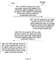
- the configuration module 310 is for configuring an uplink contention resource for multiple UEs, where the uplink contention resource includes an SR symbol for transmitting an SR and a shared symbol for transmitting uplink data.
- the receiving module 320 is for receiving the SR by using the SR symbol in the uplink contention resource.
- the receiving module 320 is further for receiving the uplink data by using the shared symbol in the uplink contention resource.
- the eNB configures the uplink contention resource for the multiple user equipments UEs, receives, by using the SR symbol in the uplink contention resource, the SR sent by the UE, and receives, by using the shared symbol in the uplink contention resource, the uplink data sent by the UE.
- a new contention-based uplink data transmission manner is provided. In this uplink data transmission manner, when failing to receive the uplink data of the UEs, the eNB may still determine, according to a successfully received SR, specific UE that sends uplink data, so that the uplink contention resource is not wasted.
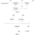
- FIG. 4 shows a block diagram of an uplink data receiving apparatus according to another embodiment of the present invention.
- the uplink data receiving apparatus may be implemented as all or a part of an eNB by using software, hardware, or a combination of software and hardware.
- the uplink data receiving apparatus may include a configuration module 310, a receiving module 320, a processing module 330, and a sending module 340.
- the configuration module 310 is for configuring an uplink contention resource for multiple user equipments UEs, where the uplink contention resource includes an SR symbol for transmitting an SR and a shared symbol for transmitting uplink data.
- the configuration module 310 is further for allocating a corresponding UE identifier to the UE. When there are multiple UEs, the configuration module 310 allocates respectively corresponding UE identifiers to the multiple UEs.
- the UE identifier includes:
- the sending module 340 is for sending DCI to each UE on a PDCCH according to a UE identifier.
- a DCI format 0 including an extension field or a newly defined DCI format CA is used as an information format of the DCI.
- An original field of the DCI format 0 includes symbol information corresponding to the shared symbol in the uplink contention resource, and a quantity and a starting location of a resource block (English: Resource Block, RB for short) occupied by the uplink contention resource.
- the extension field of the DCI format 0 includes symbol information for indicating the SR symbol, that is, the extension field carries the symbol information of the SR symbol.
- the symbol information is an SR symbol quantity, an SR symbol location, or the like.
- the SR symbol quantity is used to indicate a quantity of symbols occupied by the SR in the uplink contention resource.
- the SR symbol location is used to indicate a symbol location of the SR symbol in the uplink contention resource.
- the DCI format CA is a redesigned DCI format.
- the DCI format CA includes symbol information of the SR symbol, symbol information corresponding to the shared symbol, and a quantity and a starting location of an RB occupied by the uplink contention resource.
- the DCI format CA includes RB allocation, an SR symbol quantity, an SR symbol location, and a pilot group number.
- the RB allocation is used to indicate a location of the RB occupied by the uplink contention resource in a frequency domain.
- the SR symbol quantity is used to indicate a quantity of symbols occupied by the SR in the uplink contention resource.
- the SR symbol location is used to indicate a symbol location of the SR symbol in the uplink contention resource.
- the configuration module 310 is for allocating a corresponding code channel index to the UE.
- the configuration module 310 allocates respectively corresponding code channel indexes to the multiple UEs.
- the receiving module 320 is for receiving the SR on the SR symbol in the uplink contention resource by using a code channel corresponding to each UE.
- the apparatus further includes the processing module 330.
- the processing module 330 is for finding, according to a pre-stored first correspondence, a first cyclic shift value and a first time-domain orthogonal code that are corresponding to each code channel index.
- the processing module 330 is for dctccting, according to the first cyclic shift value and the first time-domain orthogonal code, whether signal energy on a code channel that is corresponding to the code channel index and that is on the SR symbol reaches a predetermined threshold.
- the processing module 330 is for: when the signal energy reaches the predetermined threshold, determining that the SR sent by the UE corresponding to the code channel index is received.
- the processing module 330 is for receiving, on the shared symbol in the uplink contention resource, the uplink data sent in a MU-MIMO manner.
- the processing module 330 is for determining, for each successfully received SR, a code channel index corresponding to the SR.
- the processing module 330 is for finding, according to a pre-stored second correspondence, a pilot index corresponding to the code channel index, and a second cyclic shift value and a second time-domain orthogonal code that are corresponding to the pilot index.
- the processing module 330 is for performing, according to the second cyclic shift value and the second time-domain orthogonal code, channel estimation on a DMRS carried in a reference symbol in the uplink contention resource, to obtain a channel estimation result.
- the processing module 330 is for performing MU-MIMO decoding on a data symbol in the uplink contention resource according to the channel estimation result, to obtain the uplink data.
- the processing module 330 is further for performing, according to the MCS, demodulation and channel decoding on the currently transmitted data.
- the processing module 330 is for generating NACK information when the SR is successfully received but the uplink data corresponding to the SR fails to be received.
- the sending module 340 is for sending the NACK information to the UE corresponding to the SR.
- the processing module 330 is for: when the SR is successfully received but the uplink data corresponding to the SR fails to be received, generating a UL grant for the UE corresponding to the SR.
- the sending module 340 is for sending the UL grant to the UE corresponding to the SR.
- the eNB delivers ACK information or the NACK information to the UE, so that the UE can obtain a feedback from an eNB side even if the UE fails to transmit the uplink data in a contention manner. Then, the UE determines whether to resend the uplink data or continue to transmit other uplink data, so that efficiency of communication between the eNB and the UE is improved.
- the eNB directly delivers the UL grant to the UE that fails to transmit the uplink data, so that the UE can retransmit the uplink data in a scheduling-based manner. Therefore, signaling interaction between the UE and the eNB is effectively reduced, and signaling resources on an eNB side are saved.
- the uplink data sending apparatus provided in the foregoing embodiment sends uplink data and the uplink data receiving apparatus provided in the foregoing embodiment receives uplink data
- division of the foregoing function modules is merely used as an example for description.
- the foregoing functions may be allocated to different function modules for implementation according to a requirement, that is, internal structures of the devices are divided into different function modules, to implement all or some of the foregoing described functions.
- the receiving module and the sending module may be implemented by a processor by controlling a transceiver.
- the determining module, the configuration module, and the processing module may be implemented by the processor by executing instructions stored in a memory.
- FIG. 5 shows a structural block diagram of UE according to an embodiment of the present invention.
- UE 500 includes a bus 510, and a processor 520, a memory 530, and a transceiver 540 that communicate with each other by using the bus 510.
- the memory 530 is for storing one or more instructions
- the processor 520 is for executing the instructions.
- the processor 520 is for determining an uplink contention resource, where the uplink contention resource includes an SR symbol for transmitting an uplink SR and a shared symbol for transmitting uplink data.
- the processor 520 is further for controlling the transceiver 540 to send the SR by using the SR symbol in the uplink contention resource.
- the processor 520 is further for controlling the transceiver 540 to send the uplink data by using the shared symbol in the uplink contention resource.
- the UE provided in this embodiment determines the uplink contention resource, controls the transceiver to send the SR by using the SR symbol in the uplink contention resource, and controls the transceiver to send the uplink data by using the shared symbol in the uplink contention resource.
- the eNB may still determine, according to a successfully received SR, specific UE that sends uplink data.
- the processor 520 is for: controlling, on the SR symbol in the uplink contention resource, the transceiver 540 to send the SR by using a code channel corresponding to the UE.
- the processor 520 is for controlling, on the shared symbol in the uplink contention resource, the transceiver 540 to send the uplink data in a multi-user multiple-input multiple-output MU-MIMO manner.
- the processor 520 is for controlling, on the shared symbol in the uplink contention resource, the transceiver 540 to send the uplink data in a multi-user multiple-input multiple-output MU-MIMO manner.
- the uplink data includes an MCS and currently transmitted data; and the processor 520 is for performing multiplex transmission on the MCS and the currently transmitted data by separately adding the MCS and the currently transmitted data to the uplink contention resource.
- a channel coding rate used for the MCS is lower than a channel coding rate used for the currently transmitted data.
- the processor 520 is for obtaining a UE identifier allocated by the eNB, where the UE identifier includes a CA-RNTI or an SPS-CA-RNTI; the processor 520 is for controlling the transceiver 540 to receive downlink control information DCI from a PDCCH according to the UE identifier; and the processor 520 is further for determining, from the DCI, the uplink contention resource configured by the eNB.
- a DCI format format 0 including an extension field is used for the DCI, an original field of the DCI format 0 includes symbol information corresponding to the shared symbol in the uplink contention resource, and a quantity and a starting location of an RB occupied by the uplink contention resource, and the extension field includes symbol information for indicating the SR symbol; or a DCI format CA is used for the DCI, and the DCI format CA includes symbol information of the SR symbol, symbol information corresponding to the shared symbol, and a quantity and a starting location of an RB occupied by the uplink contention resource.
- FIG. 6 shows a structural block diagram of an eNB according to an embodiment of the present invention.
- an eNB 600 includes a bus 610, and a processor 620, a memory 630, and a transceiver 640 that communicate with each other by using the bus 610.
- the memory 630 is for storing one or more instructions
- the processor 620 is for executing the instructions.
- the processor 620 is for configuring an uplink contention resource for multiple user equipments UEs, where the uplink contention resource includes an SR symbol for transmitting an uplink SR and a shared symbol for transmitting uplink data.
- the processor 620 is further for controlling the transceiver 640 to receive the SR by using the SR symbol in the uplink contention resource.
- the processor 620 is further for controlling the transceiver 640 to receive the uplink data by using the shared symbol in the uplink contention resource.
- the eNB configureds the uplink contention resource for the multiple user equipments UEs, controls the transceiver to receive the SR by using the SR symbol in the uplink contention resource, and controls the transceiver to receive the uplink data by using the shared symbol in the uplink contention resource.
- a new contention-based uplink data transmission manner is provided. In this uplink data transmission manner, when failing to receive the uplink data of the UEs, the eNB may still determine, according to a successfully received SR, specific UE that sends uplink data.
- the processor 620 is for controlling, on the SR symbol in the uplink contention resource, the transceiver 640 to receive the SR by using a code channel corresponding to each UE.
- the processor 620 is for controlling, on the shared symbol in the uplink contention resource, the transceiver 640 to receive the uplink data sent in a MU-MIMO manner.
- the shared symbol includes a reference symbol for transmitting a DMRS and a data symbol for transmitting the uplink data;
- the processor 620 is for allocating a corresponding UE identifier to the UE; and the processor 620 is for controlling the transceiver 640 to send downlink control information DCI to each UE on a PDCCH according to a UE identifier.
- a DCI format 0 including an extension field is used for the DCI, an original field of the DCI format 0 includes symbol information corresponding to the shared symbol in the uplink contention resource, and a quantity and a starting location of an RB occupied by the uplink contention resource, and the extension field includes symbol information for indicating the SR symbol; or a DCI format CA is used for the DCI, and the DCI format CA includes symbol information of the SR symbol, symbol information corresponding to the shared symbol, and a quantity and a starting location of an RB occupied by the uplink contention resource.
- FIG. 7 shows a block diagram of an uplink data sending and receiving system according to an embodiment of the present invention.
- the uplink data sending and receiving system includes an eNB 710 and UE 720.
- the UE 720 includes the uplink data sending apparatus provided in either the embodiment shown in FIG. 1 or the embodiment shown in FIG. 2 , or the UE 720 is the UE provided in the embodiment shown in FIG. 5 .
- the eNB 710 includes the uplink data receiving apparatus provided in either the embodiment shown in FIG. 3 or the embodiment shown in FIG. 4 , or the eNB 710 is the eNB provided in the embodiment shown in FIG. 6 .
- FIG. 8 shows a flowchart of an uplink data sending method according to an embodiment of the present invention.
- the uplink data sending method includes the following steps.
- Step 801 An eNB configures an uplink contention resource for multiple UEs, where the uplink contention resource includes an SR symbol for transmitting an SR and a shared symbol for transmitting uplink data.
- the uplink contention resource is a time domain resource on a PUSCH channel.
- the uplink contention resource includes at least one RB.
- the multiple UEs may share a same uplink contention resource, and send uplink data to the eNB in a contcntion-bascd sending manner.
- some symbols in the uplink contention resource are classified as SR symbols for transmitting SRs, and the other symbols in the uplink contention resource are classified as shared symbols for transmitting uplink data.
- An SR is used to notify the eNB that the UE needs to send uplink data.
- Step 802 The UE determines the uplink contention resource, where the uplink contention resource includes the SR symbol for transmitting the SR and the shared symbol for transmitting the uplink data.
- the UE receives configuration information that is of the uplink shared resource and that is sent by the eNB, and determines the uplink shared resource of the UE according to the received configuration information.
- the UE may determine the uplink shared resource by itself in the configuration manner that is agreed on in advance.
- the UE After receiving the configuration information that is of the uplink contention resource and that is sent by the eNB, the UE determines the uplink contention resource from the configuration information.
- Step 803 The UE sends the SR to the eNB by using the SR symbol in the uplink contention resource, and sends the uplink data to the eNB by using the shared symbol in the uplink contention resource.
- the UE If the UE needs to send the uplink data, the UE sends both the SR and the uplink data on a same uplink contention resource. If the multiple UEs need to send uplink data, the multiple UEs send respective SRs and respective uplink data on a same uplink contention resource.
- Step 804 The eNB receives the SR of the UE by using the SR symbol in the uplink contention resource, and receives the uplink data of the UE by using the shared symbol in the uplink contention resource.
- the UE sends the SR to the eNB by using the SR symbol in the uplink contention resource, and sends the uplink data to the eNB by using the shared symbol in the uplink contention resource, and the eNB receives the SR of the UE by using the SR symbol in the uplink contention resource, and receives the uplink data of the UE by using the shared symbol in the uplink contention resource.
- a new contention-based uplink data transmission manner is provided. In this uplink data transmission manner, when failing to receive the uplink data of the UEs, the eNB may still determine, according to a successfully received SR, specific UE that sends uplink data.
- steps related to a UE side may be independently implemented as an uplink data sending method of the UE side
- steps related to an eNB side may be independently implemented as an uplink data receiving method of the eNB side.
- an eNB configures an uplink contention resource for UE, and the uplink contention resource includes an SR symbol for transmitting an SR and a shared symbol for transmitting uplink data.
- the shared symbol includes a reference symbol and a data symbol.
- the reference symbol is used to transmit a DMRS, and the DMRS may be used by the eNB to perform channel estimation on designated UE and then receive uplink data of the designated UE.
- the data symbol is used to transmit uplink data.
- the uplink contention resource includes the SR symbol, the reference symbol, and the data symbol that have three functions.
- SR symbols in the uplink contention resource are continuously arranged or discretely arranged.
- Reference symbols are arranged in a fixed order.
- FIG. 9A and FIG. 9B separately show schematic diagrams of frame structures of a single uplink contention resource in two different arrangement manners.
- FIG. 9A is a schematic diagram of a frame structure of a single uplink contention resource in which SR symbols are continuously arranged.
- a frequency domain part of the single uplink contention resource occupies four RBs
- a time domain part includes two timeslots
- each timeslot includes seven symbols
- the other symbols are data symbols.
- FIG. 9B is a schematic diagram of a frame structure of a single uplink contention resource in which SR symbols are discretely arranged.
- the other symbols are data symbols.
- Discrete arrangement of SR symbols is applicable to a high-speed movement scenario, and this helps cope with Doppler shift by using time diversity.
- a quantity of RBs occupied by an uplink contention resource in a frequency domain is assigned by an eNB.
- Four RBs are used as an example for description in both FIG. 9A and FIG. 9B .
- the quantity of RBs is not specifically limited in this embodiment of the present invention.
- a quantity of SR symbols depends on a quantity of UEs carried on a single uplink contention resource. Three SR symbols are used as an example for description in FIG. 9A , and two SR symbols are used as an example for description in FIG. 9B .
- the quantity and an arrangement manner of SR symbols are not specifically limited in this embodiment of the present invention.
- each timeslot includes seven symbols.
- each timeslot includes six symbols, and a reference symbol is arranged at the third symbol of each timeslot.
- FIG. 9A and FIG. 9B Details are not described again in this embodiment of the present invention.
- a first point that should be noted is as follows: Each UE sends an SR on an SR symbol in an uplink contention resource by using a code channel corresponding to the UE. Correspondingly, an eNB receives the SR on the SR symbol in the uplink contention resource by using the code channel corresponding to each UE.
- the eNB can receive the SR sent by each UE. Therefore, the eNB can learn of specific UE that sends uplink data on the uplink contention resource.
- Each UE sends uplink data on a shared symbol in an uplink contention resource in a MU-MIMO manner.
- an eNB receives, on the shared symbol in the uplink contention resource, the uplink data sent by the UE in a MU-MIMO manner.
- a MU-MIMO technology is used for uplink transmission, multi-user parallel transmission may be implemented by using channel irrelevancy between all UEs.
- a premise of using the MU-MIMO technology for uplink transmission is to obtain channel estimation of each UE. Therefore, all the UEs need to use different DMRSs.
- the eNB may perform channel estimation on each UE by using a DMRS of the UE, and then perform MU-MIMO decoding according to a channel estimation result, so as to successfully receive the uplink data.
- FIG. 10A , FIG. 10B , and FIG. 10C show a flowchart of an uplink data sending method according to another embodiment of the present invention.
- the uplink data sending method includes the following steps.
- Step 1001 An eNB allocates a corresponding code channel index and a corresponding UE identifier to UE.
- the eNB allocates respectively corresponding code channel indexes and respectively corresponding UE identifiers to the multiple UEs.
- the eNB groups UEs that are in a radio resource control connected (English: Radio Resource Control-CONNECTED, RRC_CONNECTED for short) mode and on which uplink synchronization is performed.
- the eNB learns of a single-transmission data packet size, a QoS level, and channel information that are of each UE.
- the eNB may group the UEs based on the information, and configure a same uplink contention resource for multiple UEs that are classified into a same group.
- the eNB classifies UEs with approximately equal single-transmission data packet sizes to a same group. For another example, the eNB classifies UEs with different angles of arrival and irrelevant inter-UE channels to a same group.
- the eNB allocates corresponding code channel indexes and corresponding UE identifiers to UEs in a same group by using a predetermined message. There may be m UEs in a same group. The eNB allocates respectively corresponding code channel indexes and respectively corresponding UE identifiers to the m UEs in the same group.
- the predetermined message includes but is not limited to an RRC message.
- the eNB allocates both a code channel index and a UE identifier by using a same RRC message.
- the eNB separately allocates a code channel index and a UE identifier by using different RRC messages.
- the UE identifier includes a CA-RNTI and/or an SPS-CA-RNTI.
- Step 1002 The UE obtains the code channel index and the UE identifier allocated by the cNB.
- Step 1003 The eNB sends DCI to each UE on a PDCCH according to a UE identifier of the UE, where the DCI carries configuration information of an uplink contention resource.
- the eNB configures a same uplink contention resource for multiple UEs in a dynamic scheduling manner or a semi-persistent scheduling manner.
- the dynamic scheduling manner is a manner in which the eNB schedules a currently used time-frequency resource to the UEs by using signaling once.
- the semi-persistent scheduling manner is a manner in which the eNB schedules a periodically used time-frequency resource to the UEs by using signaling once.
- the eNB scrambles cyclic redundancy check (English: Cyclic Redundancy Check, CRC for short) in DCI information by using a CA-RNTI of the UE, and then sends, to the UE by using a PDCCH, the DCI information carrying the scrambled CRC.
- cyclic redundancy check English: Cyclic Redundancy Check, CRC for short
- the eNB scrambles CRC in DCI information by using an SPS-CA-RNTI of the UE, and then sends, to the UE by using a PDCCH, the DCI information carrying the scrambled CRC.
- a DCI format 0 including an extension field or a newly defined DCI format CA is used as an information format of the DCI.
- An original field of the DCI format 0 includes symbol information corresponding to a shared symbol in the uplink contention resource, and a quantity and a starting location of an RB occupied by the uplink contention resource.
- the DCI format format 0 with the extension field includes symbol information for indicating an SR symbol, that is, the extension field carries the symbol information of the SR symbol.
- the symbol information is an SR symbol quantity, an SR symbol location, or the like.
- the SR symbol quantity is used to indicate a quantity of symbols occupied by an SR in the uplink contention resource.
- the SR symbol location is used to indicate a symbol location of the SR symbol in the uplink contention resource.
- the DCI format CA is a redesigned DCI format.
- the DCI format CA includes symbol information of an SR symbol, symbol information corresponding to a shared symbol, and a quantity and a starting location of an RB occupied by the uplink contention resource.
- the DCI format CA includes RB allocation, an SR symbol quantity, an SR symbol location, and a pilot group number.
- the RB allocation is used to indicate a location of the RB occupied by the uplink contention resource in a frequency domain.
- the SR symbol quantity is used to indicate a quantity of symbols occupied by an SR in the uplink contention resource.
- the SR symbol location is used to indicate a symbol location of the SR symbol in the uplink contention rcsourcc.
- specific content of the DCI format CA includes but is not limited to the following table: Table 1 Information type Bit quantity Meaning RB allocation log 2 ⁇ N RB UL N RB UL + 1 / 2 ⁇ Indicating a location of an allocated RB, where N RB UL is a total uplink RB quantity SR symbol quantity 2 Indicating a quantity of symbols occupied by an SR SR symbol location 14 Performing mapping according to a bit location, where a bit value 1 represents an SR symbol
- a quantity of bits occupied by the RB allocation depends on the total uplink RB quantity.
- the SR symbol quantity occupies two bits, and the SR symbol location occupies 14 bits.
- a value of an i th bit is 1, it indicates that an i th symbol in the uplink contention resource is an SR symbol.
- the value of the i th bit is 0, it indicates that the i th symbol in the uplink contention resource is not an SR symbol.
- the quantities of bits occupied by the RB allocation, the SR symbol quantity, and the SR symbol location are merely used as an example for description.
- the quantities of bits occupied by the RB allocation, the SR symbol quantity, and the SR symbol location are not limited in this embodiment.
- the specific content of the DCI format CA may further include other information.
- the DCI format CA further includes a frequency hopping identifier.
- the frequency hopping identifier occupies one bit and is used to indicate whether frequency hopping occurs in two timeslots of the uplink contention resource.
- the DCI format CA when there are multiple groups of pilot resources used to generate a DMRS, the DCI format CA further carries a pilot group number.
- the pilot group number occupies two bits, and the pilot group number is used to notify UE of a group in which a currently used pilot resource is located.
- Step 1004 The UE receives, from the PDCCH according to the UE identifier, the DCI sent by the eNB.
- the UE receives, from the PDCCH by using the UE identifier, the DCI sent by the eNB. Only UE having the UE identifier can successfully descramble the DCI.
- the UE obtains, from the DCI, related resource configuration information of the uplink contention resource configured by the eNB.
- the UE When the dynamic scheduling manner is used, the UE performs descrambling by using the CA-RNTI, to obtain the DCI information.
- the UE When the semi-persistent scheduling manner is used, the UE performs descrambling by using the SPS-CA-RNTI, to obtain the DCI information.
- Step 1005 The UE finds, according to a pre-stored first correspondence, a first cyclic shift value and a first time-domain orthogonal code that are corresponding to the code channel index.
- Both the eNB and the UE store the first correspondence in advance.
- the first correspondence is a correspondence between the code channel index and each of the first cyclic shift value and the first time-domain orthogonal code.
- the first cyclic shift value and the first time-domain orthogonal code are information required by the UE to generate an SR.
- the first cyclic shift value is a cyclic shift value obtained when cyclic shift is performed on a predetermined base sequence to generate an SR sequence.
- a length of the SR sequence is a product of 12 and an RB quantity in the uplink contention resource.
- the base sequence may be a Zadoff-Chu sequence, which is referred to as a ZC sequence for short.
- the first time-domain orthogonal code refers to an orthogonal sequence that is used when time domain extension is performed on the SR sequence.
- the first time-domain orthogonal code is a DFT sequence or a Walsh sequence.
- a length of the DFT sequence is 3, and a length of the Walsh sequence is 4.
- the DFT sequence with a length of 3 is shown in Table 2: Table 2 Sequence index number Orthogonal sequence 0 [1 1 1] 1 [1 e j2 ⁇ /3 e j4 ⁇ /3 ] 2 [1 e j4 ⁇ /3 e j2 ⁇ /3 ]
- the Walsh sequence with a length of 4 is shown in Table 3: Table 3 Sequence index number Orthogonal sequence 0 [+1 +1 +1 +1] 1 [+1 -1 +1 -1] 2 [+1 -1 -1 +1] 3 [+1 +1 -1 -1]
- the UE finds the corresponding first cyclic shift value and the corresponding first time-domain orthogonal code by using the code channel index allocated by the eNB.
- Step 1006 The UE processes a predetermined base sequence by using the first cyclic shift value and the first time-domain orthogonal code, to generate an SR.
- Multiple UEs may use a same base sequence, or may use different base sequences. Generally, UEs located in a same cell use a same base sequence. A specific base sequence used by the UE is well-known by a person skilled in the art. Details are not described in this embodiment.
- the UE performs cyclic shift on the predetermined base sequence by using the first cyclic shift value, to generate the SR sequence with a length of the product of 12 and an RB quantity, and then performs time domain extension on the SR sequence by using the first time-domain orthogonal code, to generate the SR.
- Step 1007 The UE finds, according to a pre-stored second correspondence, a pilot index corresponding to the code channel index, and a second cyclic shift value and a second time-domain orthogonal code that are corresponding to the pilot index.
- Both the eNB and the UE store the second correspondence in advance.
- the second correspondence includes a correspondence between the code channel index and the pilot index, and a correspondence between the pilot index and each of the second cyclic shift value and the second time-domain orthogonal code.
- the second cyclic shift value and the second time-domain orthogonal code are information required by the UE to generate a DMRS.
- One code channel index is corresponding to only one pilot index, and one pilot index may be corresponding to more than one code channel index.
- a code channel index 01 is corresponding to a pilot index 07.
- pilot index n DMRS ⁇ 2 [w ( ⁇ ) (0) w ( ⁇ ) (1)] 0 0 [1, 1] 1 6 [1, 1] 2 3 [1, 1] 3 9 [1, 1] 4 0 [1,-1] 5 6 [1, -1] 6 3 [1, -1] 7 9 [1, -1] 8 2 [1, 1] 9 8 [1, 1] 10 5 [1, 1] 11 11 [1, 1] 12 2 [1, -1] 13 8 [1, -1] 14 5 [1, -1] 15 11 [1, -1] 16 4 [1, 1] 17 10 [1, 1] 18 7 [1, 1] 19 1 [1, 1] 20 4 [1, -1] 21 10 [1, -1] 22 7 [1, -1] 23 1 [1, -1]
- the pilot index is from 0 to 23
- the second cyclic shift value is n DMRS , ⁇ 2
- the second time-domain orthogonal code is [w ( ⁇ ) (0) w ( ⁇ ) (1)].
- pilot resources in Table 4 may be classified into three groups for use.
- Table 4 may be modified into Table 5: Pilot group number Pilot index n DMRS , ⁇ 2 w ( ⁇ ) (0) w ( ⁇ ) (1)] 00 0 0 [1, 1] 1 6 [1, 1] 2 3 [1, 1] 3 9 [1, 1] 4 0 [1, -1] 5 6 [1, -1] 6 3 [1, -1] 7 9 [1, -1] 01 0 2 [1, 1] 1 8 [1, 1] 2 5 [1, 1] 3 11 [1, 1] 4 2 [1,-1] 5 8 [1, -1] 6 5 [1, -1] 7 11 [1, -1] 02 0 4 [1, 1] 1 10 [1, 1] 2 7 [1, 1] 3 1 [1, 1] 4 4 [1, -1] 5 10 [1, -1] 6 7 [1, -1] 7 1 [1, -1]
- the eNB indicates a currently used pilot group number to the UE in the DCI information in step 1003.
- the UE After learning of the code channel index, the UE finds the corresponding pilot index by using the code channel index, and then finds the corresponding second cyclic shift value and the corresponding second time-domain orthogonal code by using the pilot index.
- the UE finds the corresponding pilot index in a currently used pilot resource group by using the code channel index.
- a pilot group number of the pilot resource group is indicated by the eNB in the DCI information.
- Step 1008 The UE processes a predetermined base sequence by using the second cyclic shift value and the second time-domain orthogonal code, to generate a DMRS.
- the base sequence used by the UE in step 1008 is generally the same as the base sequence used in step 1006.
- the UE performs cyclic shift on the predetermined base sequence by using the second cyclic shift value, to generate a reference signal sequence with a length of the product of 12 and an RB quantity, and then performs time domain extension on the reference signal sequence by using the second time-domain orthogonal code, to generate the DMRS.
- Step 1009 The UE sends the SR by adding the SR to an SR symbol in the uplink contention resource, sends the DMRS by adding the DMRS to a reference signal in the uplink contention resource, and send uplink data by adding the uplink data to a data symbol in the uplink contention resource.
- the UE sends all of the SR, the DMRS, and the uplink data on a same uplink contention resource.
- the uplink data includes an MCS and currently transmitted data.
- the UE performs multiplex transmission on the MCS and the currently transmitted data by separately adding the MCS and the currently transmitted data to data symbols at different locations in the uplink contention resource.
- a channel coding rate used for the MCS is lower than a channel coding rate used for the currently transmitted data.
- the MCS is arranged in a front resource element, so that the eNB obtains the MCS by means of decoding.
- the currently transmitted data is arranged in a back resource element, so that the eNB decodes, by using the MCS obtained by means of decoding, the data subsequently obtained by means of decoding.
- Step 1010 The eNB finds, according to the pre-stored first correspondence, a first cyclic shift value and a first time-domain orthogonal code that are corresponding to each code channel index.
- the uplink contention resource is allocated to multiple UEs, there are multiple corresponding code channel indexes. Because all the multiple UEs may send data on the uplink contention resource, the eNB needs to detect whether there is an SR on each code channel.
- the eNB finds, according to the pre-stored first correspondence, the first cyclic shift value and the first time-domain orthogonal code that are corresponding to each code channel index.
- Step 1011 The eNB detects, according to the first cyclic shift value and the first time-domain orthogonal code, whether signal energy on a code channel that is corresponding to the code channel index and that is on the SR symbol reaches a predetermined threshold.
- the eNB does not need to perform detailed decoding on an SR received on a code channel.
- the eNB only needs to detect, on the SR symbol in the uplink contention resource, whether signal energy on each code channel reaches the predetermined threshold.
- step 1014 is performed.
- the eNB determines that no SR is received on this code channel.
- Step 1012 If the signal energy reaches the predetermined threshold, the eNB determines that the SR sent by the UE corresponding to the code channel index is received.
- Step 1013 For each successfully received SR, the eNB determines a code channel index corresponding to the SR.
- the eNB For the successfully received SR, the eNB attempts to receive uplink data sent by UE corresponding to the SR. In this case, the eNB first needs to perform channel estimation by using a DMRS sent by the UE, and then receive the uplink data according to a channel estimation result.
- Step 1014 The eNB finds, according to the pre-stored second correspondence, the pilot index corresponding to the code channel index, and the second cyclic shift value and the second time-domain orthogonal code that are corresponding to the pilot index.
- Step 1015 The eNB performs, according to the second cyclic shift value and the second time-domain orthogonal code, channel estimation on the DMRS carried in the reference symbol in the uplink contention resource, to obtain a channel estimation result.
- Step 1016 The eNB performs MU-MIMO decoding on the data symbol in the uplink contention resource according to the channel estimation result, to obtain the uplink data.
- step 1014 to step 1016 are performed n times.
- the eNB after obtaining the uplink data by means of decoding, the eNB further performs, according to the MCS, demodulation and channel decoding on the currently transmitted data.
- the eNB allocates the corresponding UE identifier to the UE; the eNB sends the DCI to the multiple UEs on the PDCCH according to the UE identifiers; the UE obtains, from the DCI, the uplink contention resource configured by the eNB, sends the SR to the eNB by using the SR symbol in the uplink contention resource configured by the eNB, and sends the uplink data to the eNB by using the shared symbol in the uplink contention resource; the eNB receives the SR sent by the UE by using the SR symbol in the uplink contention resource, and receives the uplink data sent by the UE by using the shared symbol in the uplink contention resource; and the eNB sends corresponding feedback information to corresponding UE according to a successfully received SR.
- a new contention-based uplink data transmission manner is provided. In this uplink data transmission manner, when failing to receive the uplink data of the UEs, the eNB may still determine, according to a successfully received SR, specific UE that sends uplink data.
- steps related to a UE side may be independently implemented as an uplink data sending method of the UE side
- steps related to an eNB side may be independently implemented as an uplink data receiving method of the eNB side.
- the method further includes the following steps.
- Step 1017 When successfully receiving the SR and the uplink data corresponding to the SR, the eNB generates ACK information, and sends the ACK information to the corresponding UE.
- the eNB For UE, if the eNB successfully receives an SR and uplink data that are sent by the UE, the eNB generates acknowledgement information, that is, ACK information.
- the eNB may send the ACK information to the UE by using a designated downlink resource on a physical HARQ indicator channel (English: Physical Hybrid ARQ Indicator Channel, PHICH for short).
- a resource location of the designated downlink resource may be obtained through calculation by using a resource location of the uplink contention resource and a DMRS of the UE. For a calculation formula, refer to a related LTE communications protocol.
- Step 1018 The UE receives the ACK information.
- the UE receives the ACK information by using the designated downlink resource on the PHICH channel.
- the UE may continue to send other uplink data in the contention mode.
- Step 1019 When successfully receiving the SR but failing to receive the uplink data corresponding to the SR, the eNB generates NACK information, and sends the NACK information to the corresponding UE.
- the eNB For UE, if the eNB successfully receives an SR sent by the UE but fails to receive uplink data sent by the UE, the eNB generates negative acknowledgement information, that is, NACK information.
- the eNB may send the NACK information to the UE by using a designated downlink resource on a PHICH.
- a resource location of the designated downlink resource may be obtained through calculation by using a resource location of the uplink contention resource and a DMRS of the UE. For a calculation formula, refer to a related LTE communications protocol.
- Step 1020 The UE receives the NACK information.
- the UE receives the NACK information by using the designated downlink resource on the PHICH channel.
- the UE may resend the uplink data in the contention mode.
- the eNB delivers the ACK information or the NACK information to the UE, so that the UE can obtain a feedback from an eNB side even if the UE fails to transmit the uplink data in a contention manner. Then, the UE determines whether to resend the uplink data or continue to transmit other uplink data, so that efficiency of communication between the eNB and the UE is improved.
- step 1019 and step 1020 may be replaced by step 1021 to step 1024 for implementation.
- Step 1021 When successfully receiving the SR but failing to receive the uplink data corresponding to the SR, the eNB generates a UL grant for the UE corresponding to the SR.
- the UL grant is indication information that is used when the eNB allocates an uplink transmission resource to the UE in a scheduling based manner. That is, the UL grant carries configuration information of the uplink transmission resource exclusively allocated by the eNB to the UE.
- Step 1022 The eNB sends the UL grant to the UE.
- the eNB sends the UL grant to the UE by using a DCI format 0 on a PDCCH channel.
- Step 1023 The UE receives the UL grant fed back by the eNB.
- the UL grant is sent by the eNB when the eNB successfully receives the SR but fails to receive the uplink data corresponding to the SR.
- Step 1024 The UE resends the uplink data according to the UL grant.
- the eNB directly delivers the UL grant to the UE that fails to transmit the uplink data, so that the UE can retransmit the uplink data in a scheduling-based manner. Therefore, signaling interaction between the UE and the eNB is effectively reduced, and signaling resources on an eNB side are saved.
- steps related to a UE side may be independently implemented as an uplink data sending method of the UE side
- steps related to an eNB side may be independently implemented as an uplink data receiving method of the eNB side.
- the program may be stored in a computer-readable storage medium.
- the storage medium may include: a read-only memory, a magnetic disk, or an optical disc.
Applications Claiming Priority (1)
| Application Number | Priority Date | Filing Date | Title |
|---|---|---|---|
| PCT/CN2015/085470 WO2017015910A1 (zh) | 2015-07-29 | 2015-07-29 | 上行数据发送装置、接收装置及方法 |
Publications (3)
| Publication Number | Publication Date |
|---|---|
| EP3316644A1 EP3316644A1 (en) | 2018-05-02 |
| EP3316644A4 EP3316644A4 (en) | 2018-06-27 |
| EP3316644B1 true EP3316644B1 (en) | 2020-12-02 |
Family
ID=57884014
Family Applications (1)
| Application Number | Title | Priority Date | Filing Date |
|---|---|---|---|
| EP15899262.8A Active EP3316644B1 (en) | 2015-07-29 | 2015-07-29 | Transmission device, receiving device and method for uplink data |
Country Status (6)
| Country | Link |
|---|---|
| US (1) | US10499420B2 (zh) |
| EP (1) | EP3316644B1 (zh) |
| JP (1) | JP2018524951A (zh) |
| CN (1) | CN106576355B (zh) |
| AU (1) | AU2015403755B2 (zh) |
| WO (1) | WO2017015910A1 (zh) |
Families Citing this family (10)
| Publication number | Priority date | Publication date | Assignee | Title |
|---|---|---|---|---|
| US11395325B2 (en) | 2016-04-01 | 2022-07-19 | Lg Electronics Inc. | Method for transmitting downlink control information for sidelink scheduling in wireless communication system and terminal using same |
| EP4216645A1 (en) * | 2016-04-01 | 2023-07-26 | LG Electronics Inc. | Method for transmitting downlink control information for sidelink scheduling in wireless communication system and terminal using same |
| US11497047B2 (en) * | 2017-09-25 | 2022-11-08 | Qualcomm Incorporated | User equipment-specific scheduling request repetitions |
| CN110870366B (zh) * | 2017-11-28 | 2020-12-22 | Oppo广东移动通信有限公司 | 在用户设备中分配资源的方法和用户设备 |
| GB2570899B (en) * | 2018-02-08 | 2021-01-06 | Tcl Communication Ltd | Grant-based uplink transmission |
| WO2019153233A1 (en) * | 2018-02-09 | 2019-08-15 | Qualcomm Incorporated | Configuration of non-orthogonal dmrs for noma |
| US11432369B2 (en) * | 2018-06-19 | 2022-08-30 | Apple Inc. | Reference signal and control information processing in 5G-NR wireless systems |
| WO2020051735A1 (zh) * | 2018-09-10 | 2020-03-19 | Oppo广东移动通信有限公司 | 通信方法、终端设备和网络设备 |
| KR20200048636A (ko) * | 2018-10-30 | 2020-05-08 | 삼성전자주식회사 | 무선 통신 시스템에서 상향링크 전송을 위한 장치 및 방법 |
| CN115413029A (zh) * | 2021-05-10 | 2022-11-29 | 华为技术有限公司 | 一种信息传输的方法及通信装置 |
Family Cites Families (15)
| Publication number | Priority date | Publication date | Assignee | Title |
|---|---|---|---|---|
| DE602005022502D1 (de) * | 2005-08-22 | 2010-09-02 | Ericsson Telefon Ab L M | Kommunikationssystem und verfahren zum übertragen von daten zwischen einem endgerät und netzbetriebsmitteln |
| WO2011068358A2 (ko) * | 2009-12-01 | 2011-06-09 | 엘지전자 주식회사 | 경쟁기반 물리 상향링크 데이터 채널을 통한 데이터의 송수신 방법 및 이를 위한 장치 |
| JP2011142533A (ja) * | 2010-01-08 | 2011-07-21 | Sharp Corp | 移動局装置、基地局装置、無線通信システム、無線通信方法および集積回路 |
| CN102123399B (zh) * | 2010-01-08 | 2014-01-01 | 华为技术有限公司 | 调度请求的方法及装置 |
| JP5706047B2 (ja) * | 2011-11-01 | 2015-04-22 | エルジー エレクトロニクス インコーポレイティド | 無線通信システムにおいて端末のサウンディング参照信号伝送決定方法及びそのための端末 |
| CA2859961C (en) * | 2011-12-23 | 2017-05-16 | Blackberry Limited | A method implemented in an enodeb base station |
| US8929319B2 (en) * | 2011-12-23 | 2015-01-06 | Blackberry Limited | Updating scheduling request resources |
| WO2014000201A1 (zh) | 2012-06-28 | 2014-01-03 | 华为技术有限公司 | 上行资源分配方法及装置 |
| US9900844B2 (en) * | 2014-01-13 | 2018-02-20 | Samsung Electronics Co., Ltd. | Uplink transmissions for dual connectivity |
| US9872313B2 (en) | 2014-10-02 | 2018-01-16 | Qualcomm Incorporated | Contention based uplink transmissions for latency reduction |
| US10129858B2 (en) * | 2014-11-25 | 2018-11-13 | Qualcomm Incorporated | Low latency physical layer design for contention-based uplink channels |
| CN104581972A (zh) * | 2014-12-30 | 2015-04-29 | 同济大学 | 基于fdm方式发送多个上行调度请求的传输方法和系统 |
| CN104601309B (zh) * | 2014-12-30 | 2018-04-27 | 同济大学 | 基于tdm方式发送多个上行调度请求的传输方法和系统 |
| AR103887A1 (es) * | 2015-03-09 | 2017-06-14 | ERICSSON TELEFON AB L M (publ) | Canal pucch breve en canal spucch de enlace ascendente |
| US9717079B2 (en) * | 2015-07-14 | 2017-07-25 | Motorola Mobility Llc | Method and apparatus for selecting a resource assignment |
-
2015
- 2015-07-29 JP JP2018504229A patent/JP2018524951A/ja active Pending
- 2015-07-29 AU AU2015403755A patent/AU2015403755B2/en not_active Ceased
- 2015-07-29 CN CN201580045059.5A patent/CN106576355B/zh active Active
- 2015-07-29 EP EP15899262.8A patent/EP3316644B1/en active Active
- 2015-07-29 WO PCT/CN2015/085470 patent/WO2017015910A1/zh active Application Filing
-
2018
- 2018-01-29 US US15/882,629 patent/US10499420B2/en active Active
Non-Patent Citations (1)
| Title |
|---|
| None * |
Also Published As
| Publication number | Publication date |
|---|---|
| AU2015403755B2 (en) | 2019-02-21 |
| US20180160443A1 (en) | 2018-06-07 |
| JP2018524951A (ja) | 2018-08-30 |
| WO2017015910A1 (zh) | 2017-02-02 |
| EP3316644A4 (en) | 2018-06-27 |
| US10499420B2 (en) | 2019-12-03 |
| AU2015403755A1 (en) | 2018-02-22 |
| CN106576355A (zh) | 2017-04-19 |
| CN106576355B (zh) | 2019-12-13 |
| EP3316644A1 (en) | 2018-05-02 |
Similar Documents
| Publication | Publication Date | Title |
|---|---|---|
| US11729793B2 (en) | Scheduling uplink transmissions | |
| US10368352B2 (en) | Data transmission method and apparatus by device to device terminal in wireless communication system | |
| EP3316644B1 (en) | Transmission device, receiving device and method for uplink data | |
| EP3280087B1 (en) | Method for transmitting and receiving signal in wireless communication system and device therefor | |
| US10264560B2 (en) | Uplink signal transmitting method and user equipment, and uplink signal receiving method and base station | |
| EP3603261B1 (en) | Multiple starting and ending positions for scheduled downlink transmission on unlicensed spectrum | |
| EP3393191B1 (en) | Method and apparatus for data transmission of device-to-device user equipment in wireless communication system | |
| EP2732593B1 (en) | Method for transmitting or receiving pdcch and user equipment or base station for the method | |
| CN107534992B (zh) | 上行链路数据发送方法和用户设备以及上行链路数据接收方法和基站 | |
| US11184924B2 (en) | Multiple starting positions for uplink transmission on unlicensed spectrum | |
| US10314036B2 (en) | Method and apparatus for transmitting data by device-to-device terminal in wireless communication system | |
| JP2018509028A (ja) | 上りリンク信号を送信する方法及び使用者器機、並びに上りリンク信号を受信する方法及び基地局 | |
| CN114175830A (zh) | 在无线通信系统中发送和接收物理上行链路共享信道(pusch)的方法、装置和系统 | |
| JP2022528231A (ja) | 下りリンク制御情報を送信する方法及び基地局、並びに下りリンク制御情報を受信する方法、ユーザ機器及び格納媒体 | |
| CN114424661A (zh) | 在无线通信系统中发送和接收物理上行链路共享信道(pusch)的方法、装置和系统 | |
| CN115336213A (zh) | Harq-ack发送方法、用户设备和存储介质及harq-ack接收方法和基站 | |
| CN111434167A (zh) | 无线通信系统中发送上行数据的方法和装置 | |
| US20230224095A1 (en) | Method and user equipment for transmitting harq-ack information, and base station for receiving harq-ack information | |
| KR20210125414A (ko) | 피드백에 기초한 사이드링크 통신을 위한 방법 및 장치 |
Legal Events
| Date | Code | Title | Description |
|---|---|---|---|
| STAA | Information on the status of an ep patent application or granted ep patent |
Free format text: STATUS: THE INTERNATIONAL PUBLICATION HAS BEEN MADE |
|
| PUAI | Public reference made under article 153(3) epc to a published international application that has entered the european phase |
Free format text: ORIGINAL CODE: 0009012 |
|
| STAA | Information on the status of an ep patent application or granted ep patent |
Free format text: STATUS: REQUEST FOR EXAMINATION WAS MADE |
|
| 17P | Request for examination filed |
Effective date: 20180125 |
|
| AK | Designated contracting states |
Kind code of ref document: A1 Designated state(s): AL AT BE BG CH CY CZ DE DK EE ES FI FR GB GR HR HU IE IS IT LI LT LU LV MC MK MT NL NO PL PT RO RS SE SI SK SM TR |
|
| AX | Request for extension of the european patent |
Extension state: BA ME |
|
| A4 | Supplementary search report drawn up and despatched |
Effective date: 20180530 |
|
| RIC1 | Information provided on ipc code assigned before grant |
Ipc: H04W 74/02 20090101ALI20180524BHEP Ipc: H04W 72/12 20090101AFI20180524BHEP |
|
| DAV | Request for validation of the european patent (deleted) | ||
| DAX | Request for extension of the european patent (deleted) | ||
| STAA | Information on the status of an ep patent application or granted ep patent |
Free format text: STATUS: EXAMINATION IS IN PROGRESS |
|
| 17Q | First examination report despatched |
Effective date: 20190607 |
|
| GRAP | Despatch of communication of intention to grant a patent |
Free format text: ORIGINAL CODE: EPIDOSNIGR1 |
|
| STAA | Information on the status of an ep patent application or granted ep patent |
Free format text: STATUS: GRANT OF PATENT IS INTENDED |
|
| INTG | Intention to grant announced |
Effective date: 20200728 |
|
| GRAS | Grant fee paid |
Free format text: ORIGINAL CODE: EPIDOSNIGR3 |
|
| GRAA | (expected) grant |
Free format text: ORIGINAL CODE: 0009210 |
|
| STAA | Information on the status of an ep patent application or granted ep patent |
Free format text: STATUS: THE PATENT HAS BEEN GRANTED |
|
| AK | Designated contracting states |
Kind code of ref document: B1 Designated state(s): AL AT BE BG CH CY CZ DE DK EE ES FI FR GB GR HR HU IE IS IT LI LT LU LV MC MK MT NL NO PL PT RO RS SE SI SK SM TR |
|
| REG | Reference to a national code |
Ref country code: GB Ref legal event code: FG4D |
|
| REG | Reference to a national code |
Ref country code: AT Ref legal event code: REF Ref document number: 1342356 Country of ref document: AT Kind code of ref document: T Effective date: 20201215 Ref country code: CH Ref legal event code: EP |
|
| REG | Reference to a national code |
Ref country code: IE Ref legal event code: FG4D |
|
| REG | Reference to a national code |
Ref country code: DE Ref legal event code: R096 Ref document number: 602015063093 Country of ref document: DE |
|
| PG25 | Lapsed in a contracting state [announced via postgrant information from national office to epo] |
Ref country code: NO Free format text: LAPSE BECAUSE OF FAILURE TO SUBMIT A TRANSLATION OF THE DESCRIPTION OR TO PAY THE FEE WITHIN THE PRESCRIBED TIME-LIMIT Effective date: 20210302 Ref country code: RS Free format text: LAPSE BECAUSE OF FAILURE TO SUBMIT A TRANSLATION OF THE DESCRIPTION OR TO PAY THE FEE WITHIN THE PRESCRIBED TIME-LIMIT Effective date: 20201202 Ref country code: FI Free format text: LAPSE BECAUSE OF FAILURE TO SUBMIT A TRANSLATION OF THE DESCRIPTION OR TO PAY THE FEE WITHIN THE PRESCRIBED TIME-LIMIT Effective date: 20201202 Ref country code: GR Free format text: LAPSE BECAUSE OF FAILURE TO SUBMIT A TRANSLATION OF THE DESCRIPTION OR TO PAY THE FEE WITHIN THE PRESCRIBED TIME-LIMIT Effective date: 20210303 |
|
| REG | Reference to a national code |
Ref country code: NL Ref legal event code: MP Effective date: 20201202 |
|
| REG | Reference to a national code |
Ref country code: AT Ref legal event code: MK05 Ref document number: 1342356 Country of ref document: AT Kind code of ref document: T Effective date: 20201202 |
|
| PG25 | Lapsed in a contracting state [announced via postgrant information from national office to epo] |
Ref country code: BG Free format text: LAPSE BECAUSE OF FAILURE TO SUBMIT A TRANSLATION OF THE DESCRIPTION OR TO PAY THE FEE WITHIN THE PRESCRIBED TIME-LIMIT Effective date: 20210302 Ref country code: SE Free format text: LAPSE BECAUSE OF FAILURE TO SUBMIT A TRANSLATION OF THE DESCRIPTION OR TO PAY THE FEE WITHIN THE PRESCRIBED TIME-LIMIT Effective date: 20201202 Ref country code: LV Free format text: LAPSE BECAUSE OF FAILURE TO SUBMIT A TRANSLATION OF THE DESCRIPTION OR TO PAY THE FEE WITHIN THE PRESCRIBED TIME-LIMIT Effective date: 20201202 Ref country code: PL Free format text: LAPSE BECAUSE OF FAILURE TO SUBMIT A TRANSLATION OF THE DESCRIPTION OR TO PAY THE FEE WITHIN THE PRESCRIBED TIME-LIMIT Effective date: 20201202 |
|
| PG25 | Lapsed in a contracting state [announced via postgrant information from national office to epo] |
Ref country code: HR Free format text: LAPSE BECAUSE OF FAILURE TO SUBMIT A TRANSLATION OF THE DESCRIPTION OR TO PAY THE FEE WITHIN THE PRESCRIBED TIME-LIMIT Effective date: 20201202 Ref country code: NL Free format text: LAPSE BECAUSE OF FAILURE TO SUBMIT A TRANSLATION OF THE DESCRIPTION OR TO PAY THE FEE WITHIN THE PRESCRIBED TIME-LIMIT Effective date: 20201202 |
|
| REG | Reference to a national code |
Ref country code: LT Ref legal event code: MG9D |
|
| PG25 | Lapsed in a contracting state [announced via postgrant information from national office to epo] |
Ref country code: EE Free format text: LAPSE BECAUSE OF FAILURE TO SUBMIT A TRANSLATION OF THE DESCRIPTION OR TO PAY THE FEE WITHIN THE PRESCRIBED TIME-LIMIT Effective date: 20201202 Ref country code: CZ Free format text: LAPSE BECAUSE OF FAILURE TO SUBMIT A TRANSLATION OF THE DESCRIPTION OR TO PAY THE FEE WITHIN THE PRESCRIBED TIME-LIMIT Effective date: 20201202 Ref country code: SM Free format text: LAPSE BECAUSE OF FAILURE TO SUBMIT A TRANSLATION OF THE DESCRIPTION OR TO PAY THE FEE WITHIN THE PRESCRIBED TIME-LIMIT Effective date: 20201202 Ref country code: LT Free format text: LAPSE BECAUSE OF FAILURE TO SUBMIT A TRANSLATION OF THE DESCRIPTION OR TO PAY THE FEE WITHIN THE PRESCRIBED TIME-LIMIT Effective date: 20201202 Ref country code: RO Free format text: LAPSE BECAUSE OF FAILURE TO SUBMIT A TRANSLATION OF THE DESCRIPTION OR TO PAY THE FEE WITHIN THE PRESCRIBED TIME-LIMIT Effective date: 20201202 Ref country code: SK Free format text: LAPSE BECAUSE OF FAILURE TO SUBMIT A TRANSLATION OF THE DESCRIPTION OR TO PAY THE FEE WITHIN THE PRESCRIBED TIME-LIMIT Effective date: 20201202 Ref country code: PT Free format text: LAPSE BECAUSE OF FAILURE TO SUBMIT A TRANSLATION OF THE DESCRIPTION OR TO PAY THE FEE WITHIN THE PRESCRIBED TIME-LIMIT Effective date: 20210405 |
|
| PG25 | Lapsed in a contracting state [announced via postgrant information from national office to epo] |
Ref country code: AT Free format text: LAPSE BECAUSE OF FAILURE TO SUBMIT A TRANSLATION OF THE DESCRIPTION OR TO PAY THE FEE WITHIN THE PRESCRIBED TIME-LIMIT Effective date: 20201202 |
|
| REG | Reference to a national code |
Ref country code: DE Ref legal event code: R097 Ref document number: 602015063093 Country of ref document: DE |
|
| PG25 | Lapsed in a contracting state [announced via postgrant information from national office to epo] |
Ref country code: IS Free format text: LAPSE BECAUSE OF FAILURE TO SUBMIT A TRANSLATION OF THE DESCRIPTION OR TO PAY THE FEE WITHIN THE PRESCRIBED TIME-LIMIT Effective date: 20210402 |
|
| PLBE | No opposition filed within time limit |
Free format text: ORIGINAL CODE: 0009261 |
|
| STAA | Information on the status of an ep patent application or granted ep patent |
Free format text: STATUS: NO OPPOSITION FILED WITHIN TIME LIMIT |
|
| PG25 | Lapsed in a contracting state [announced via postgrant information from national office to epo] |
Ref country code: AL Free format text: LAPSE BECAUSE OF FAILURE TO SUBMIT A TRANSLATION OF THE DESCRIPTION OR TO PAY THE FEE WITHIN THE PRESCRIBED TIME-LIMIT Effective date: 20201202 Ref country code: IT Free format text: LAPSE BECAUSE OF FAILURE TO SUBMIT A TRANSLATION OF THE DESCRIPTION OR TO PAY THE FEE WITHIN THE PRESCRIBED TIME-LIMIT Effective date: 20201202 |
|
| 26N | No opposition filed |
Effective date: 20210903 |
|
| PG25 | Lapsed in a contracting state [announced via postgrant information from national office to epo] |
Ref country code: DK Free format text: LAPSE BECAUSE OF FAILURE TO SUBMIT A TRANSLATION OF THE DESCRIPTION OR TO PAY THE FEE WITHIN THE PRESCRIBED TIME-LIMIT Effective date: 20201202 Ref country code: SI Free format text: LAPSE BECAUSE OF FAILURE TO SUBMIT A TRANSLATION OF THE DESCRIPTION OR TO PAY THE FEE WITHIN THE PRESCRIBED TIME-LIMIT Effective date: 20201202 |
|
| PG25 | Lapsed in a contracting state [announced via postgrant information from national office to epo] |
Ref country code: ES Free format text: LAPSE BECAUSE OF FAILURE TO SUBMIT A TRANSLATION OF THE DESCRIPTION OR TO PAY THE FEE WITHIN THE PRESCRIBED TIME-LIMIT Effective date: 20201202 |
|
| REG | Reference to a national code |
Ref country code: DE Ref legal event code: R119 Ref document number: 602015063093 Country of ref document: DE |
|
| REG | Reference to a national code |
Ref country code: CH Ref legal event code: PL |
|
| GBPC | Gb: european patent ceased through non-payment of renewal fee |
Effective date: 20210729 |
|
| PG25 | Lapsed in a contracting state [announced via postgrant information from national office to epo] |
Ref country code: MC Free format text: LAPSE BECAUSE OF FAILURE TO SUBMIT A TRANSLATION OF THE DESCRIPTION OR TO PAY THE FEE WITHIN THE PRESCRIBED TIME-LIMIT Effective date: 20201202 |
|
| REG | Reference to a national code |
Ref country code: BE Ref legal event code: MM Effective date: 20210731 |
|
| PG25 | Lapsed in a contracting state [announced via postgrant information from national office to epo] |
Ref country code: LI Free format text: LAPSE BECAUSE OF NON-PAYMENT OF DUE FEES Effective date: 20210731 Ref country code: GB Free format text: LAPSE BECAUSE OF NON-PAYMENT OF DUE FEES Effective date: 20210729 Ref country code: DE Free format text: LAPSE BECAUSE OF NON-PAYMENT OF DUE FEES Effective date: 20220201 Ref country code: CH Free format text: LAPSE BECAUSE OF NON-PAYMENT OF DUE FEES Effective date: 20210731 |
|
| PG25 | Lapsed in a contracting state [announced via postgrant information from national office to epo] |
Ref country code: IS Free format text: LAPSE BECAUSE OF FAILURE TO SUBMIT A TRANSLATION OF THE DESCRIPTION OR TO PAY THE FEE WITHIN THE PRESCRIBED TIME-LIMIT Effective date: 20210402 Ref country code: LU Free format text: LAPSE BECAUSE OF NON-PAYMENT OF DUE FEES Effective date: 20210729 Ref country code: FR Free format text: LAPSE BECAUSE OF NON-PAYMENT OF DUE FEES Effective date: 20210731 |
|
| PG25 | Lapsed in a contracting state [announced via postgrant information from national office to epo] |
Ref country code: IE Free format text: LAPSE BECAUSE OF NON-PAYMENT OF DUE FEES Effective date: 20210729 Ref country code: BE Free format text: LAPSE BECAUSE OF NON-PAYMENT OF DUE FEES Effective date: 20210731 |
|
| PG25 | Lapsed in a contracting state [announced via postgrant information from national office to epo] |
Ref country code: HU Free format text: LAPSE BECAUSE OF FAILURE TO SUBMIT A TRANSLATION OF THE DESCRIPTION OR TO PAY THE FEE WITHIN THE PRESCRIBED TIME-LIMIT; INVALID AB INITIO Effective date: 20150729 |
|
| PG25 | Lapsed in a contracting state [announced via postgrant information from national office to epo] |
Ref country code: CY Free format text: LAPSE BECAUSE OF FAILURE TO SUBMIT A TRANSLATION OF THE DESCRIPTION OR TO PAY THE FEE WITHIN THE PRESCRIBED TIME-LIMIT Effective date: 20201202 |
|
| PG25 | Lapsed in a contracting state [announced via postgrant information from national office to epo] |
Ref country code: MK Free format text: LAPSE BECAUSE OF FAILURE TO SUBMIT A TRANSLATION OF THE DESCRIPTION OR TO PAY THE FEE WITHIN THE PRESCRIBED TIME-LIMIT Effective date: 20201202 |