EP3316390A2 - System for controlling multiple cooling fans for battery pack - Google Patents
System for controlling multiple cooling fans for battery pack Download PDFInfo
- Publication number
- EP3316390A2 EP3316390A2 EP16814650.4A EP16814650A EP3316390A2 EP 3316390 A2 EP3316390 A2 EP 3316390A2 EP 16814650 A EP16814650 A EP 16814650A EP 3316390 A2 EP3316390 A2 EP 3316390A2
- Authority
- EP
- European Patent Office
- Prior art keywords
- motors
- cooling fans
- motor
- control board
- cooling fan
- Prior art date
- Legal status (The legal status is an assumption and is not a legal conclusion. Google has not performed a legal analysis and makes no representation as to the accuracy of the status listed.)
- Granted
Links
Images


Classifications
-
- H—ELECTRICITY
- H01—ELECTRIC ELEMENTS
- H01M—PROCESSES OR MEANS, e.g. BATTERIES, FOR THE DIRECT CONVERSION OF CHEMICAL ENERGY INTO ELECTRICAL ENERGY
- H01M10/00—Secondary cells; Manufacture thereof
- H01M10/42—Methods or arrangements for servicing or maintenance of secondary cells or secondary half-cells
- H01M10/425—Structural combination with electronic components, e.g. electronic circuits integrated to the outside of the casing
-
- H—ELECTRICITY
- H01—ELECTRIC ELEMENTS
- H01M—PROCESSES OR MEANS, e.g. BATTERIES, FOR THE DIRECT CONVERSION OF CHEMICAL ENERGY INTO ELECTRICAL ENERGY
- H01M10/00—Secondary cells; Manufacture thereof
- H01M10/60—Heating or cooling; Temperature control
- H01M10/61—Types of temperature control
- H01M10/613—Cooling or keeping cold
-
- H—ELECTRICITY
- H01—ELECTRIC ELEMENTS
- H01M—PROCESSES OR MEANS, e.g. BATTERIES, FOR THE DIRECT CONVERSION OF CHEMICAL ENERGY INTO ELECTRICAL ENERGY
- H01M10/00—Secondary cells; Manufacture thereof
- H01M10/60—Heating or cooling; Temperature control
- H01M10/62—Heating or cooling; Temperature control specially adapted for specific applications
- H01M10/625—Vehicles
-
- H—ELECTRICITY
- H01—ELECTRIC ELEMENTS
- H01M—PROCESSES OR MEANS, e.g. BATTERIES, FOR THE DIRECT CONVERSION OF CHEMICAL ENERGY INTO ELECTRICAL ENERGY
- H01M10/00—Secondary cells; Manufacture thereof
- H01M10/60—Heating or cooling; Temperature control
- H01M10/63—Control systems
-
- H—ELECTRICITY
- H01—ELECTRIC ELEMENTS
- H01M—PROCESSES OR MEANS, e.g. BATTERIES, FOR THE DIRECT CONVERSION OF CHEMICAL ENERGY INTO ELECTRICAL ENERGY
- H01M10/00—Secondary cells; Manufacture thereof
- H01M10/60—Heating or cooling; Temperature control
- H01M10/65—Means for temperature control structurally associated with the cells
- H01M10/656—Means for temperature control structurally associated with the cells characterised by the type of heat-exchange fluid
- H01M10/6561—Gases
- H01M10/6563—Gases with forced flow, e.g. by blowers
-
- H—ELECTRICITY
- H02—GENERATION; CONVERSION OR DISTRIBUTION OF ELECTRIC POWER
- H02K—DYNAMO-ELECTRIC MACHINES
- H02K11/00—Structural association of dynamo-electric machines with electric components or with devices for shielding, monitoring or protection
- H02K11/20—Structural association of dynamo-electric machines with electric components or with devices for shielding, monitoring or protection for measuring, monitoring, testing, protecting or switching
- H02K11/21—Devices for sensing speed or position, or actuated thereby
- H02K11/215—Magnetic effect devices, e.g. Hall-effect or magneto-resistive elements
-
- H—ELECTRICITY
- H02—GENERATION; CONVERSION OR DISTRIBUTION OF ELECTRIC POWER
- H02K—DYNAMO-ELECTRIC MACHINES
- H02K9/00—Arrangements for cooling or ventilating
- H02K9/02—Arrangements for cooling or ventilating by ambient air flowing through the machine
- H02K9/04—Arrangements for cooling or ventilating by ambient air flowing through the machine having means for generating a flow of cooling medium
- H02K9/06—Arrangements for cooling or ventilating by ambient air flowing through the machine having means for generating a flow of cooling medium with fans or impellers driven by the machine shaft
-
- H—ELECTRICITY
- H01—ELECTRIC ELEMENTS
- H01M—PROCESSES OR MEANS, e.g. BATTERIES, FOR THE DIRECT CONVERSION OF CHEMICAL ENERGY INTO ELECTRICAL ENERGY
- H01M10/00—Secondary cells; Manufacture thereof
- H01M10/42—Methods or arrangements for servicing or maintenance of secondary cells or secondary half-cells
- H01M10/425—Structural combination with electronic components, e.g. electronic circuits integrated to the outside of the casing
- H01M2010/4271—Battery management systems including electronic circuits, e.g. control of current or voltage to keep battery in healthy state, cell balancing
-
- H—ELECTRICITY
- H01—ELECTRIC ELEMENTS
- H01M—PROCESSES OR MEANS, e.g. BATTERIES, FOR THE DIRECT CONVERSION OF CHEMICAL ENERGY INTO ELECTRICAL ENERGY
- H01M10/00—Secondary cells; Manufacture thereof
- H01M10/42—Methods or arrangements for servicing or maintenance of secondary cells or secondary half-cells
- H01M10/425—Structural combination with electronic components, e.g. electronic circuits integrated to the outside of the casing
- H01M2010/4278—Systems for data transfer from batteries, e.g. transfer of battery parameters to a controller, data transferred between battery controller and main controller
-
- H—ELECTRICITY
- H02—GENERATION; CONVERSION OR DISTRIBUTION OF ELECTRIC POWER
- H02K—DYNAMO-ELECTRIC MACHINES
- H02K11/00—Structural association of dynamo-electric machines with electric components or with devices for shielding, monitoring or protection
- H02K11/30—Structural association with control circuits or drive circuits
- H02K11/33—Drive circuits, e.g. power electronics
-
- Y—GENERAL TAGGING OF NEW TECHNOLOGICAL DEVELOPMENTS; GENERAL TAGGING OF CROSS-SECTIONAL TECHNOLOGIES SPANNING OVER SEVERAL SECTIONS OF THE IPC; TECHNICAL SUBJECTS COVERED BY FORMER USPC CROSS-REFERENCE ART COLLECTIONS [XRACs] AND DIGESTS
- Y02—TECHNOLOGIES OR APPLICATIONS FOR MITIGATION OR ADAPTATION AGAINST CLIMATE CHANGE
- Y02E—REDUCTION OF GREENHOUSE GAS [GHG] EMISSIONS, RELATED TO ENERGY GENERATION, TRANSMISSION OR DISTRIBUTION
- Y02E60/00—Enabling technologies; Technologies with a potential or indirect contribution to GHG emissions mitigation
- Y02E60/10—Energy storage using batteries
Definitions
- the present invention relates to a multiple cooling fan control system for a battery pack, which is capable of using a wire harness made of a minimum number of wirings by driving a plurality of cooling fans for cooling the battery pack while using a single control board.
- an electric vehicle is a vehicle developed as a countermeasure against exhaust gas, and has some advantages of less noise and no exhaust gas in comparison with a conventional internal combustion engine equipped vehicle.
- Such an electric vehicle is a pollution-free vehicle that drives an electric motor with electric energy and rotates wheels through a power transmission device, in which a battery is used as a power source necessary for driving force.
- the battery used in the electric vehicle has the advantage of generating no exhaust gas and the very small noise because a battery in which a plurality of rechargeable secondary cells are packed is used as a main power source.
- the battery has an internal resistance, heat is generated in charging and discharging. Therefore, the battery temperature rises as the battery is repeatedly charged and discharged.
- the life of such a battery is shortened when the battery is continuously used at a high temperature. Therefore, in order to protect the battery, the charge/discharge current is limited when the battery is at a high temperature. In this case, however, the propulsive force of the vehicle is not sufficiently obtained, and in the hybrid vehicle, the fuel consumption of the internal combustion engine deteriorates to worsen fuel efficiency.
- a battery management system (BMS) module is installed in a battery pack assembly of an electric vehicle and/or a hybrid vehicle, to thus play a role of preventing safety accidents such as ignition and explosion of the battery due to overcharge or overdischarge of the battery, or temperature rise when using the battery, and keeping the battery in an optimal state.
- BMS battery management system
- the BMS module measures the voltage and temperature of each battery to determine whether the battery is abnormal.
- the electrode terminal of each battery is electrically connected to a printed circuit board (PCB) and a temperature sensor, and the voltage of each electrode terminal measured by the PCB and the temperature of each electrode terminal measured by the temperature sensor are transferred to the BMS module, which controls multiple cooling fans to cool multiple battery packs.
- PCB printed circuit board
- Patent Document 1 discloses an apparatus for controlling battery cooling in an electric vehicle, the battery cooling control apparatus including: a battery tray configured such that a plurality of batteries are arranged in respective predetermined areas; a battery temperature detector for detecting temperatures of the plurality of batteries; a BMS controller for generating a drive control signal for an independent cooling control of the battery for each of the predetermined areas to reduce a temperature difference between the temperatures of the plurality of batteries detected through the battery temperature detector; cooling fans installed individually in the predetermined areas of the battery tray and driven in response to the drive control signal supplied from the BMS controller to cool batteries arranged in the predetermined areas; and a cooling fan drive controller that is electrically connected between the BMS controller and the cooling fans to intermittently flow the drive control signal supplied from the BMS controller to the cooling fans.
- a cooling fan control cable which is set to classify each cooling fan driving state into a high, medium, low, and off state, is electrically connected to the BMS controller, so that independent cooling fan control reduces the temperature difference between batteries to suppress battery performance degradation.
- the cooling fan driving state is set to one of the four states, and the control has not been made to a continuous value.
- axial-flow fans are used as a plurality of conventional cooling fans for cooling batteries
- the plurality of conventional cooling fans are modularized with guides, and installed in battery packs.
- a plurality of the modularized cooling fans are integrated and fixed by mounting brackets.
- each of the cooling fans is connected to a drive motor for driving respective impellers through a pair of power lines, a FG signal line for indicating the rotational speed of the motor, and a control line (duty ratio value for pulse width modulation (PWM) control).
- PWM pulse width modulation
- the present invention has been made to solve the above problems, and it is an object of the present invention to provide a multiple cooling fan control system for a battery pack capable of mounting a signal processing processor capable of performing various functions on a control board by configuring the control board using a single printed circuit board having a large size covering a plurality of cooling fans to utilize a space between a motor and another motor, in order to cool the battery pack.
- a multiple cooling fan control system for a battery pack which includes: a first housing having a plurality of suction ports arranged at intervals; a plurality of cooling fans arranged corresponding to the plurality of suction ports and generating a ventilation power; a second housing coupled to receive the plurality of cooling fans on a rear surface of the first housing and having a plurality of discharge ports; and a control device installed inside the second housing for controlling the cooling fans and supplying electric power to the cooling fans, wherein the control device drives includes at least one signal processing device for driving the plurality of cooling fans in accordance with motor drive information received from a battery management system (BMS).
- BMS battery management system
- the control device may include: a control board installed inside the second housing and having the plurality of cooling fans fixedly installed therein; the at least one signal processing device mounted on the control board and each generating a plurality of drive signals for controlling the plurality of cooling fans in accordance with the motor drive information received from the battery management system (BMS); a plurality of drivers mounted on the control board and each driving a motor of each of the plurality of cooling fans in accordance with the plurality of drive signals generated from the at least one signal processing device; and a wire harness for connecting the battery management system (BMS) and the control board, and transmitting and receiving a power source for driving the motors of the plurality of cooling fans, driving information of the motors, and status information of the motors, wherein the power supply for driving the plurality of motors and the drive information of the motors can be commonly received through the wire harness.
- BMS battery management system
- the multiple cooling fan control system may further include a communication module which is provided between the wire harness and the at least one signal processing device to receive the driving information of the motors and transmit the status information of the motors
- the wire harness may include three wires for commonly receiving an external power supply (such as Vdd and Gnd) and a power control signal (such as Power Control), and two wires for the communication module.
- the communication module may employ any one of a controller area network (CAN) communication system, a local interconnect network (LIN) communication system, and a universal asynchronous receiver/transmitter (UART) communication system.
- CAN controller area network
- LIN local interconnect network
- UART universal asynchronous receiver/transmitter
- Each of the cooling fans may include: a motor in which a stator and a rotor are formed in a radial gap type; and impellers which rotate together with the rotor and suck air in an axial direction of the suction ports to discharge air in a radial direction thereof.
- the motor may include a bearing bushing having a throughhole formed at a central portion of the bearing bushing and whose one end is fixed to the control board; the stator whose inner circumferential portion is fixed to the outer circumferential portion of the bearing bushing; a pair of sleeve bearings spaced apart from each other in the throughhole of the bearing bushing; a rotating shaft rotatably supported by the pair of sleeve bearings; and the rotor disposed at an outer circumferential portion of the stator with an air gap therebetween, the rotor having the rotating shaft coupled to a central portion of a rotor support and impellers coupled to an outer circumferential portion of the rotor.
- the control board may include a main body that is disposed on a rear surface of the first housing in which the suction ports are installed, and the at least one signal processing device and the drivers are disposed; and a plurality of connection portions protruding from the main body toward a rear portion of the suction ports and to which the bearing bushing is fixed wherein the motor is supported to the bearing bushing.
- the at least one signal processing device may receive the duty ratio value required for the RPM control of the motor from the battery management system (BMS) through a communication input of the wire harness, and may output the current, voltage, temperature, and state information of the motor to the battery management system (BMS).
- BMS battery management system
- the at least one signal processing device may calculate a current rotational speed of the motor from a rotor position signals of the motor received from a hall sensor provided adjacent to the motor and may transmit the rotational speed signal of the motor to the battery management system (BMS).
- BMS battery management system
- the multiple cooling fan control system for a battery pack may further include a plurality of guide portions having a cochlea structure and collecting air radially discharged by the cooling fans to be integrally formed with the first housing to guide an air flow to one side of the cooling fans; and a plurality of duct portions integrally formed with the second housing to connect between each of the guide portions and each of the discharge ports.
- a multiple cooling fan control system for a battery pack which includes: a housing having a plurality of suction ports and a plurality of discharge ports on one side and the other side of the housing, respectively; a plurality of cooling fans having a plurality of impellers and motors installed in the housing in correspondence to the plurality of suction ports; and a control device for controlling driving of the plurality of cooling fans to cool the battery pack.
- the control device may include: a control board installed inside the housing and having the plurality of cooling fans fixedly installed therein; at least one signal processing device mounted on the control board and each generating a plurality of drive signals for controlling the plurality of cooling fans in accordance with motor drive information received from a battery management system (BMS); a plurality of drivers mounted on the control board and each driving a motor of each of the plurality of cooling fans in accordance with the plurality of drive signals generated from the at least one signal processing device; and a wire harness for connecting the battery management system (BMS) and the control board, and transmitting and receiving a power source for driving the motors of the plurality of cooling fans, driving information of the motors, and status information of the motors, wherein the power supply for driving the motors of the plurality of cooling fans and the drive information of the motors can be commonly received through the wire harness.
- BMS battery management system
- the at least one signal processing device may control the RPM of each motor by performing a proportional-integral-derivative (PID) control to reach a target RPM received from the battery management system (BMS), and may detect the overcurrent, voltage, and temperature of each motor and compare the detected overcurrent, voltage, and temperature with predetermined reference values, to thus stop the motor drive when the detected values are larger than predetermined reference values.
- PID proportional-integral-derivative
- the at least one signal processing device may limit the drive output with respect to a motor in which an abnormality occurs when an abnormality occurs in one of the plurality of motors, and may drive the rest of the motors beyond the normal driving power, to thereby control to obtain the same air volume as before the occurrence of the abnormality.
- a control board may be configured by using a single printed circuit board having a large size to cover a plurality of cooling fans to utilize a space between a motor and another motor for cooling.the battery pack, to thereby mount a processor for signal processing that can perform various functions on the control board.
- a signal processing processor may be mounted on a control board of a single printed circuit board, and a plurality of cooling fans may be directly mounted on the control board, so that a harness having a minimum number of wirings may be used to connect to a battery management system (BMS).
- BMS battery management system
- the air volume of the remaining cooling fans may be increased, so that the overall air volume can be kept identically to before the occurrence of the abnormality.
- a control of a plurality of cooling fans can be operated independently or through a centralized control to thus achieve stabilization of the system.
- the battery cooling apparatus to which the present invention is applied includes: a plurality of suction ports 32, 34, and 36 installed on a side surface of a battery pack (not shown) and through which air passing through the battery pack (not shown) is sucked; a housing 10 provided with a plurality of discharge ports 40 and 42 through which air is discharged to the outside; a plurality of cooling fans 20 which are installed at intervals in the housing 10 so as to generate a ventilation power; and a control board 50 which is installed in the housing 10 and electrically connected to the cooling fans 20 to control the cooling fans 20 and supply electric power to the cooling fans 20.
- the battery pack includes a plurality of battery cells spaced apart from each other to form one battery pack.
- a battery cooling apparatus is installed on one side of the battery pack. When the battery cooling apparatus is driven, air is sucked into spaces between the battery cells, and each battery cell is cooled while the air passing between the cells.
- suction ducts in which external air is sucked may be provided on the other side of the battery pack, that is, on the opposite side of the side where the cooling apparatus is installed.
- the housing 10 includes: a first housing 12 in which the plurality of suction ports 32, 34, and 36, the plurality of cooling fans 20 corresponding to the plurality of suction ports 32, 34, and 36; and the control board 50 are arranged; and a second housing 14 coupled to the first housing 12 in the form of a cover and having the discharge ports 40 and 42 formed in a rear or upper side of the second housing 14.
- the plurality of cooling fans 20 are disposed in the first housing 12, and each of the cooling fans 20 is a centrifugal blower, in which impellers 84 having a sirocco fan structure are connected to a rotating shaft 74 of a rotor 82 so as to radially discharge air flowing in an axial direction of the rotating shaft 74.Further, the outer side of each of the impellers 84 has a cochlear structure, and guide portions 62 for guiding an air flow in one direction by collecting the air radially discharged by the impellers 84 of the cooling fans 20 are formed in the same as the number of the cooling fans 20.For example, when there are three cooling fans 20 (e.g., 22, 24, and 26), three guide portions 62 are formed in the first housing 12.
- An air discharge portion 64 through which air of each of the cooling fans 20 is discharged is formed at an upper end of each of the guide portions 62.
- the air discharge portion 64 is connected to a duct portion 66 formed in the second housing 14 and the exit of each of the duct portions 66 is connected to the discharge ports 40 and 42 through which the air collected in the duct portion is discharged to the outside at the rear upper end of the second housing 14.
- the discharge ports 40 and 42 may be formed at the rear end of the upper portion of the second housing 14 and may be formed as one discharge port, or two discharge ports. In addition, the discharge ports may be formed as three discharge ports in the same as the number of the cooling fans. The illustrated embodiment has two discharge ports 40 and 42.
- the discharge ports 40 and 42 are formed on the upper rear side of the second housing 14 so that air is discharged to the rear side of the second housing 14.
- the discharge ports may be formed on the upper surface of the second housing 14 so that air can be discharged in the upward direction of the second housing 14.
- the battery cooling apparatus can freely change the positions of the discharge ports in accordance with the characteristics of a place where a battery pack of an electric automobile or the like is installed, thereby improving the compatibility.
- the second housing 14 is hermetically coupled to the first housing 12 and is in close contact with one surface of the battery pack.
- the edge of the second housing 14 is in close contact with the edge of the battery pack and a space is provided on the inner surface of the second housing 14 so that air passing through the battery cells can be introduced into the space.
- the battery cooling apparatus is provided with the plurality of cooling fans 22, 24, and 26 and the plurality of suction ports 32, 34, and 36 so as to be disposed on one side of the battery pack. Accordingly, an air flow may be made to uniformly cool the whole surface of the battery cells, so that the battery cells are prevented from being locally cooled. That is, when the number of the cooling fans 20 is three, the number of the suction ports 32, 34, and 36 is also three, and the three suction ports 32, 34, and 36 are arranged at a certain interval on one surface of the battery pack. Accordingly, an air flow may be distributed so as to evenly cool the whole surface of the battery pack.
- the cooling fans 20 may include a first cooling fan 22, a second cooling fan 24, and a third cooling fan 26, which are installed at predetermined intervals in the first housing 12.
- the cooling fans 20 may be two or three or more depending on the size of the battery pack.
- the first to third cooling fans 22, 24 and 26 include first to third motors 5-1 to 5-3, each motor having a stator 80 and a rotor 82 formed in a radial gap type, and impellers 84 connected to a rotating shaft 74 of the rotor 82, respectively.
- Each of the first to third motors 5-1 to 5-3 may be constituted by, for example, a core type brushless direct-current (BLDC) single-phase motor.
- the stator 80 is fixed to the outer circumference of a bearing bushing 72 having a throughhole at a center of the bearing bushing 72 and made of, for example, brass.
- a pair of sleeve bearings 86 and 88 is installed at an interval in the throughhole of the bearing bushing 72, and the rotating shaft 74 is rotatably supported on the pair of sleeve bearings 86 and 88.
- the control board 50 for driving and controlling the first to third cooling fans 22, 24, and 26 is disposed in the space formed by the first housing 12 and the second housing 14.
- the control board 50 may adopt a fixed structure, for example, by being fixed to the second housing 14 and then pressing the first housing 12.In this case, the control board 50 is assembled in such a manner that the control board 50 is coupled to a securing hook or an escape preventing groove formed integrally with the second housing 14 without using a separate fixing bolt or securing device.
- the guide portions 62 protruding from the first housing 12 can be pressed and fixed to the control board 50.
- One end of the bearing bushing 72 passes through the throughhole of the control board 50 as shown in FIGS. 9 and 10 , and then is bent and fixed to the control board 50.
- the stator 80 includes a stator core 80a coupled to the outer circumference of the bearing bushing 72 and a stator coil 80b wound around a bobbin formed on the outer circumference of the stator core 80a.
- the stator 80 is fixed to the control board 50 via the bearing bushing 72.
- the start and end terminals of the stator coil 80b are connected to a driver to be described later via terminal pins 80c fixed to the control board 50.
- a magnet 82a and a back yoke 82b constituting the rotor 82 are formed in an annular shape with an air gap on the outer periphery of the stator 80.
- the rotor 82 is integrally formed with the rotating shaft 74 at a central portion of the rotor 82 via a rotor support body 85.
- the impeller 84 having a sirocco fan structure is provided on the rotor support body 85, in which a plurality of blades are formed integrally with the rotor support body 85 so that air is sucked in the axial direction of the rotor 82 and air is radially discharged from the rotor 82.
- the control board 50 includes: a main body 54 disposed corresponding to the lower side of the rear surface of the first housing 12 and fixed to the second housing 14; a first connection portion 51 protruded from one side of the main body 54 and electrically connected to the first cooling fan 22; a second connection portion 51 protruded from the center of the main body 54 and electrically connected to the second cooling fan 24; and a third connection portion 53 protruded from the other side of the main body 54 and electrically connected to the third cooling fan 26.
- the control board 50 shown in FIGS. 9 and 10 has a configuration in which the first to third connection portions 51 to 53 are protruded from the main body 54, but may have a rectangular shape having a size corresponding to the bottom of the second housing 14.
- the second housing 14 may have a groove on the bottom thereof and the control board 50 may be disposed without having a step on the bottom groove.
- the multiple cooling fan control system for a battery pack is implemented by being mounted on the single control board 50 shown in FIG. 10 .
- control board 50 is configured by using a single printed circuit board (PCB) having a large size which covers the plurality of cooling fans 22, 24, and 26 to utilize a space between a cooling fan (or motor) and another cooling fan (or motor) in order to cool the battery pack.
- a signal processing processor such as CPU capable of performing various functions may be mounted on the control board.
- the signal processing processor is mounted on the single control board 50, and the control board 50 is provided with a controller area network (CAN) communication unit 7 used for control of the interior of a vehicle.
- CAN controller area network
- the multi-cooling fan control system for a battery pack which can be easily connected to the battery management system (BMS), can be constructed using a wire harness 91, 92, or 93 made of a minimum number of wirings.
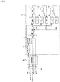
- the multiple cooling fan control system for a battery pack includes three first to third control units (denoted as 3-1 to 3-3 and labeled as CPU1 to CPU3) corresponding to three cooling fans 22, 24, and 26 for driving the first to third motors (denoted as 5-1 to 5-3 and labeled as M1 to M3) for the cooling fans 22, 24, and 26, respectively.
- the first to third drivers (denoted as 4-1 to 4-3 and labeled as DRV1 to DRV3) are connected to the first to third control units 3-1 to 3-3, and the first to third motors 5-1 to 5-3 are connected to the first to third drivers 4-1 to 4-3.
- the first to third control units 3-1 to 3-3 are connected to first to third Hall sensors (denoted as 6-1 to 6-3 and labeled as HS1-HS3) which are provided adjacent to the first to third motors 5-1 to 5-3, to receive rotor position signals (H1-H3) of the respective motors, which are detected from the first to third Hall sensors 6-1 to 6-3.
- first to third Hall sensors denoted as 6-1 to 6-3 and labeled as HS1-HS3
- H1-H3 rotor position signals
- the first to third motors 5-1 to 5-3 preferably employ a single-phase drive type BLDC motor, and may, of course, use other types of motors.
- Each of the first to third control units (CPU1 to CPU3) 3-1 to 3-3 may be configured as a signal processing device such as a microcomputer or a microprocessor, and may be connected to a battery management system (BMS) and receive a duty ratio value required for a motor RPM control from the battery management system (BMS) as a communication input, generate a PWM drive signal whose pulse width is controlled in accordance with the received duty ratio, to then be applied to the first to third drivers (DRV1 to DRV3) 4-1 to 4-3, and detect current, voltage, temperature, and status information applied to the first to third motors (M1 to M3) 5-1 to 5-3 to then be transmitted to the battery management system (BMS) via the communication input.
- BMS battery management system
- the first to third control units 3-1 to 3-3 calculate the current rotational speeds of the first to third motors 5-1 to 5-3 from the rotor position signals (H1 to H3) of the respective motors received from the first to third hall sensors (HS1 to HS3) 6-1 to 6-3 and transmit the rotational speed signals (PFM1 to PFM3) of the respective motors to the battery management system (BMS).
- BMS battery management system
- the first to third drivers (DRV1 to DRV3) 4-1 to 4-3 may be constituted by, for example, a dual-mode P-channel and N-channel switching transistor as a single-phase full-wave driving circuit, and drive the first to third motors 5-1 to 5-3 according to the PWM drive signal applied from the third control units 3-1 to 3-3.
- the first to third drivers (DRV1 to DRV3) 4-1 to 4-3 may be constituted by a full-wave driving method or a half-wave driving method, and the circuit configuration may be changed according to the driving method.
- the number of signal lines connected to the motors 5-1 to 5-3 may vary.
- the first to third control units 3-1 to 3-3, the first to third drivers 4-1 to 4-3, and the first to third Hall sensors 6-1 to 6-3 constituting the multiple cooling fan control system according to some embodiments of the present invention, are mounted on the single control board 50a provided on the rear surface of the first housing 12.
- control board 50a includes a power control circuit 1 which receives external power (Vdd and Gnd) of DC 48V applied from an external source (such as a battery pack) and a power control signal (Power Control) applied from the battery management system (BMS) and applies a motor drive voltage of DC 12V to the first to third drivers 4-1 to 4-3, and a constant voltage circuit 2 which receives the voltage of the power control circuit 1, and generates a driving voltage of DC 5V necessary for driving the first to third control units 3-1 to 3-3.
- Vdd and Gnd external power
- Power Control Power Control
- BMS battery management system
- the power control circuit 1 has an inverse voltage prevention function and shuts off the power supply to cut off the output and reduce standby power when the cooling fans 22, 24 and 26 are not operated according to a power control signal (Power Control) applied from the battery management system (BMS).
- Power Control a power control signal applied from the battery management system (BMS).
- the control board 50a is provided with a wire harness 91 including a 7-pin connector connected with seven wires from the outside. External power (Vdd and Gnd) of DC 48V, a power control signal (Power Control), a communication input received and transmitted between the control board 50a and the battery management system (BMS), and motor rotational speed signals PFM1 to PFM3 transmitted to the battery management system (BMS), are transmitted and received via the wire harness 91.
- Vdd and Gnd External power
- Power Control Power Control
- BMS battery management system
- PFM1 to PFM3 transmitted to the battery management system
- the communication input is used to receive a duty ratio value required for motor RPM control from the battery management system (BMS) and transmit the current, voltage, temperature and status information of the respective motors to the battery management system (BMS).
- the external power supply Vdd and Gnd
- the power control Power Control
- the communication input Input
- the control board 50a and the first to third control units 3-1 to 3-3, the first to third drivers 4-1 to 4-3, and the power supply device including the power control circuit 1 and the constant voltage circuit 2 constitutes a control device for controlling the cooling fans.
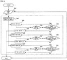
- the multiple cooling fan control system for a battery pack controls the multiple cooling fans for the battery pack according to the flowchart shown in FIG. 4 .
- a motor drive voltage of DC 12V and a drive voltage of DC 5V are generated from the power control circuit 1 and the constant voltage circuit 2, respectively, to then be applied to the first to third drivers 4-1 to 4-3 and the first to third control units 3-1 to 3-3. Accordingly, the first to third control units 3-1 to 3-3 and the first to third drivers 4-1 to 4-3 are activated.
- the first to third control units 3-1 to 3-3 receive the duty ratio values of the PWM drive signals corresponding to the target RPMs of the respective motors from the communication input commonly received from the battery management system (BMS) (S12), and generate PWM driving signals based on the received duty ratio values, respectively, to drive the first to third motors 5-1 to 5-3, respectively (S13).
- BMS battery management system
- the first to third control units 3-1 to 3-3 receive the rotor position signals H1-H3 of the respective motors received from the first to third Hall sensors (HS1 to HS3) 6-1 to 6-3, and alternately turn on switching transistors included in the first to third drivers 4-1 to 4-3 by referring to the received rotor position signals (H1-H3) of the respective motors, to thereby apply respective PWM driving signals to the stator coils. Accordingly, the first to third drivers 4-1 to 4-3 apply the PWM drive signals to the first to third motors 5-1 to 5-3, respectively, to thereby drive the rotors of the motors, respectively.
- the first to third control units 3-1 to 3-3 detect RPMs of the first to third motors 5-1 to 5-3 based on the received rotor position signals (H1-H3) of the respective motors and transmit the motor rotational speed signals (PFM1 to PFM3) to the battery management system (BMS), and also perform the proportional-integral-derivative (PID) control to reach the target RPMs received from the battery management system (BMS) to thus control the RPMs of the first to third motors 5-1 to 5-3 (S14).
- PPM1 to PFM3 motor rotational speed signals
- PID proportional-integral-derivative
- the first to third control units 3-1 to 3-3 detect the overcurrent, the voltage and the temperature flowing in the respective motors and compare them with predetermined reference values (S15). If the detected value is larger than a predetermined reference value, the motor drive is stopped (S16).
- the first to third control units 3-1 to 3-3 since the first to third control units 3-1 to 3-3 are provided on the control board 50a, the first to third control units 3-1 to 3-3 detect the overcurrent, voltage and temperature respectively flowing in the first to third motors 5-1 to 5-3, and compare the detected overcurrent, voltage and temperature with predetermined reference values, respectively, to detect the states of the respective motors. If an abnormality occurs in one of the three motors, the drive output with respect to the motor in which the abnormality occurs is limited, and only the remaining two motors are normally driven or driven beyond the normal driving power. Accordingly, it is possible to control the three motors so as to obtain the air volume generated by the three cooling fans 22, 24, and 26.
- the multiple cooling fan control system for a battery pack commonly receives the duty ratio values of the PWM driving signals required for controlling the target RPMs of three motors from the battery management system (BMS) to one communication input line, and drives the first to third motors 5-1 to 5-3 with the same command in the control board 50a.
- BMS battery management system
- the first to third motors 5-1 to 5-3 for driving the impellers 84 of the three cooling fans 22, 24 and 26, that is, the stators 80 are mounted and fixed directly onto the single control board 50a of increased size. Accordingly, the output terminals of the first to third drivers 4-1 to 4-3 are directly connected to the stator coils 80b of the respective motors. In addition, the first to third Hall sensors 6-1 to 6-3 for detecting the rotor position signals of the respective motors are also directly mounted and fixed onto the single control board 50a.
- the wire harness 91 can be constituted by the four wirings for receiving in common the external power sources (Vdd and Gnd), the power control signal, and the communication input and the three wirings necessary for transmitting the motor rotational speed signals (PFM1 to PFM3) of the respective motors to the battery management system (BMS).
- the number of wirings of the wire harness 91 can be made to be greatly reduced as compared with the conventional one.
- the first to third control units 3-1 to 3-3 are mounted on the control board 50a, only the target RPM control signals are received from the battery management system (BMS) and thus a distributed control for independently controlling the first to third motors 5-1 to 5-3 can be implemented.
- BMS battery management system
- control board should include three first to third control units 3-1 to 3-3, and the RPMs of the first to third motors 5-1 to 5-3 should be controlled.
- present invention is not limited to the first embodiment, but the first and third motors 5-1 to 5-3 can be controlled by using one control unit 3-1 on the control board as in the second and third embodiments.
- the multiple cooling fan control system for a battery pack includes first to third motors 5-1 to 5- 3 by using only the first control unit 3-1 to control the three cooling fans 22, 24, and 26.
- the first to third drivers 4-1 to 4-3 are connected to the first control unit 3-1, and the first to third drivers 4-1 to 4-3 are connected to the first to third motors 5-1 to 5-3, respectively.
- the first control unit 3-1 detects the rotor position signals (H1 to H3) of the respective motors from the first to third Hall sensors 6-1 to 6-3 provided adjacent to the first to third motors 5-1 to 5-3.
- the second embodiment of the present invention is similar to the first embodiment except that one control unit 3-1 is used. Therefore, the same elements are given the same reference numerals, and a detailed description thereof will be omitted.
- the first control unit (CPU1) 3-1 receives duty ratio values via the communication input, as a control signal for controlling the RPMs of the first to third motors (M1 to M3) 5-1 to 5-3 from the battery management system (BMS).
- BMS battery management system
- the first control unit (CPU1) 3-1 sequentially receives the duty ratio values for the first to third motors (M1-M3) 5-1 to 5-3 as the communication input and sequentially generates PWM drive signals whose pulse widths are controlled in accordance with the received duty ratio values of the respective motors, to then sequentially apply the PWM drive signals to the first to third drivers (DRV1 to DRV3) 4-1 to 4-3 and detect the current, voltage, temperature, and status information applied to the first to third motors (M1 to M3) 5-1 to 5-3 and transmit the detected current, voltage, temperature, and status information to the battery management system (BMS) via the communication input.
- DRV1 to DRV3 first to third drivers
- BMS battery management system
- the first control unit 3-1 calculates the current rotational speeds of the first to third motors (M1 to M3) 5-1 to 5-3 from the rotor position signals (H1-H3) of the respective motors received from the first through third Hall sensors (HS1-HS3) 6-1 to 6-3, and transmits the rotation speed signals (PFM1 to PFM3) of the respective motors to the battery management system (BMS).
- BMS battery management system
- the multiple cooling fan control system for a battery pack controls the multiple cooling fans for the battery pack according to the flowchart shown in FIG. 5 .
- the first control unit 3-1 sequentially receives the duty ratio values of the PWM drive signals corresponding to the target RPMs of the three motors from the communication input received from the battery management system (BMS), and generates PWM driving signals based on the received duty ratio values, to drive the first to third motors 5-1 to 5-3 (S22-S24).
- the first control unit 3-1 receives the rotor position signals (H1-H3) of the respective motors received from the first to third Hall sensors (HS1 to HS3) 6-1 to 6-3, and alternately turn on switching transistors included in the first to third drivers 4-1 to 4-3 by referring to the received rotor position signals (H1-H3) of the respective motors, to thereby apply respective PWM driving signals to the stator coils.
- the first to third drivers 4-1 to 4-3 apply the PWM drive signals to the first to third motors 5-1 to 5-3, respectively, to thereby drive the rotors of the motors, respectively (S25-S27).
- the first control unit 3-1 detects RPMs of the first to third motors 5-1 to 5-3 based on the received rotor position signals H1-H3 of the respective motors and transmits the motor rotational speed signals (PFM1 to PFM3) to the battery management system (BMS), and also perform the proportional-integral-derivative (PID) control to reach the target RPMs received from the battery management system (BMS) to thus control the RPMs of the first to third motors 5-1 to 5-3 (S28-S30).
- PFM1 to PFM3 motor rotational speed signals
- PID proportional-integral-derivative
- the first control unit 3-1 detects the overcurrent, the voltage and the temperature flowing in the respective motors and compares them with predetermined reference values (S31-S33). If the detected value is larger than a predetermined reference value, the motor drive is stopped (S34-S36).
- the wire harness 92 can be constituted by the four wirings for receiving in common the external power sources (Vdd and Gnd), the power control signal, and the communication input and the three wirings necessary for transmitting the motor rotational speed signals (PFM1 to PFM3) of the respective motors to the battery management system (BMS).
- the number of wirings of the wire harness 92 can be made to be greatly reduced as compared with the conventional one.
- the first control unit 3-1 since the first control unit 3-1 is mounted on the control board 50b, only the control signals are received from the battery management system (BMS) and the first to third motors 5-1 to 5- 3 can be independently controlled.
- BMS battery management system
- the first control unit 3-1 and the first to third motors 5-1 to 5-3 for driving the impellers 84 of the three cooling fans 22, 24 and 26, that is, the stators 80 are mounted and fixed directly onto the single control board 50a of increased size. Accordingly, the output terminals of the first to third drivers 4-1 to 4-3 are directly connected to the stator coils 80b of the respective motors. In addition, the first to third Hall sensors 6-1 to 6-3 for detecting the rotor position signals of the respective motors are also directly mounted and fixed onto the single control board 50b.
- the multiple cooling fan control system for a battery pack employs a method of controlling three cooling fans 22, 24, and 26 by controlling driving of the first to third motors 5-1 to 5-3 by using only the first control unit 3-1in a manner similar to the second embodiment.
- the third embodiment is different from the second embodiment in that the information necessary for communication is transmitted and received between the control board 50c and the battery management system (BMS) by using the CAN communication unit 7 as a communication module. Therefore, in the third embodiment, the same components as those in the second embodiment are denoted by the same reference numerals, and a detailed description thereof will be omitted.
- the first control unit 3-1 is connected in a network to the battery management system (BMS) via the CAN communication unit 7, the first control unit 3-1 is connected to the first to third drivers 4-1 through 4-3, and the first to third motors 5-1 to 5-3 are connected to the first to third drivers 4-1 to 4-3, respectively.
- BMS battery management system
- the first control unit 3-1 detects the rotor position signals H1 to H3 of the respective motors from the first to third Hall sensors 6-1 to 6-3 provided adjacent to the first to third motors 5-1 to 5-3.
- the CAN communication unit 7 may be implemented as a CAN communication module that is generally used for controlling the inside of a vehicle.
- the CAN communication is used for data transmission and control between an ECU and various information communication systems and entertainment systems constituting nodes inside a vehicle through a CAN data bus made of two data wirings, in which master-slave data communication is performed as a standard communication protocol designed for a microcontroller or devices to communicate with each other, without a separate host computer in a vehicle.
- the CAN communication unit 7 performs packet data communication between the control board 50c and the battery management system (BMS) in a CAN communication manner to transmit and receive the communication input including the motor RPMs, the current, voltage, temperature, and status information of each of the motors, and motor rotational speed signals PFM1 to PFM3 of the respective motors.
- BMS battery management system
- the CAN communication unit 7 should perform data communication using the CAN communication method.
- LIN local interconnect network
- UART universal asynchronous receiver/transmitter
- the first control unit (CPU1) 3-1 receives the motor RPMs required for motor control from the battery management system (BMS) in the CAN communication method via the CAN communication unit 7, and transmits the current, voltage, temperature, and status information of each of the motors and the motor rotation speed signals (PFM1 to PFM3) of the respective motors.
- BMS battery management system
- the multiple cooling fan control system for a battery pack controls the multiple cooling fans for the battery pack according to the flowchart shown in FIG. 6 .
- the first control unit 3-1 receives the packet data from the battery management system (BMS) via the CAN communication unit 7 and calculates the duty ratio values of the PWM drive signals corresponding to the target RPMs of the three motors contained in the packet data (S42).
- the first control unit 3-1 generates the PWM drive signals for driving the first to third motors 5-1 to 5-3 based on the duty ratio values of the PWM drive signals corresponding to the received target RPMs of the three motors.
- the first control unit 3-1 receives the rotor position signals (H1-H3) of the respective motors received from the first to third Hall sensors (HS1 to HS3) 6-1 to 6-3, and alternately turn on switching transistors included in the first to third drivers 4-1 to 4-3 by referring to the received rotor position signals (H1-H3) of the respective motors, to thereby apply respective PWM driving signals to the stator coils.
- the first to third drivers 4-1 to 4-3 apply the PWM drive signals to the first to third motors 5-1 to 5-3, respectively, to thereby drive the rotors of the motors, respectively (S43-S45).
- the first control unit 3-1 performs PID control of each motor to determine the state of the motor so that the first to third motors 5-1 to 5-3 reach the target RPMs (S46-S54) in the same manner as steps S28-S36 in FIG. 5 .
- the wire harness 93 can be constituted by the three wirings for receiving in common the external power sources (Vdd and Gnd), and the power control signal, and the two wirings necessary for CAN communication with the battery management system (BMS) via the CAN communication unit 7.
- the number of wirings of the wire harness 93 can be made to be greatly reduced as compared with the conventional one.
- the first control unit 3-1 since the first control unit 3-1 is mounted on the control board 50c, only the control signals are received from the battery management system (BMS) and the first to third motors 5-1 to 5- 3 can be independently controlled.
- BMS battery management system
- the present invention is not limited to controlling three cooling fans and can be applied even when the number of cooling fans is increased or decreased as required.
- the present invention can be applied to a multiple cooling fan control system for a battery pack, which is capable of using a wire harness made of a minimum number of wirings by driving a plurality of cooling fans for cooling the battery pack while using a single control board.
Landscapes
- Engineering & Computer Science (AREA)
- Manufacturing & Machinery (AREA)
- Chemical & Material Sciences (AREA)
- Chemical Kinetics & Catalysis (AREA)
- Electrochemistry (AREA)
- General Chemical & Material Sciences (AREA)
- Microelectronics & Electronic Packaging (AREA)
- Power Engineering (AREA)
- Automation & Control Theory (AREA)
- Secondary Cells (AREA)
Abstract
Description
- The present invention relates to a multiple cooling fan control system for a battery pack, which is capable of using a wire harness made of a minimum number of wirings by driving a plurality of cooling fans for cooling the battery pack while using a single control board.
- Generally, an electric vehicle is a vehicle developed as a countermeasure against exhaust gas, and has some advantages of less noise and no exhaust gas in comparison with a conventional internal combustion engine equipped vehicle.
- Such an electric vehicle is a pollution-free vehicle that drives an electric motor with electric energy and rotates wheels through a power transmission device, in which a battery is used as a power source necessary for driving force.
- The battery used in the electric vehicle has the advantage of generating no exhaust gas and the very small noise because a battery in which a plurality of rechargeable secondary cells are packed is used as a main power source.
- However, since the battery has an internal resistance, heat is generated in charging and discharging. Therefore, the battery temperature rises as the battery is repeatedly charged and discharged.
- In addition, the life of such a battery is shortened when the battery is continuously used at a high temperature. Therefore, in order to protect the battery, the charge/discharge current is limited when the battery is at a high temperature. In this case, however, the propulsive force of the vehicle is not sufficiently obtained, and in the hybrid vehicle, the fuel consumption of the internal combustion engine deteriorates to worsen fuel efficiency.
- For this reason, a battery management system (BMS) module is installed in a battery pack assembly of an electric vehicle and/or a hybrid vehicle, to thus play a role of preventing safety accidents such as ignition and explosion of the battery due to overcharge or overdischarge of the battery, or temperature rise when using the battery, and keeping the battery in an optimal state.
- The BMS module measures the voltage and temperature of each battery to determine whether the battery is abnormal. The electrode terminal of each battery is electrically connected to a printed circuit board (PCB) and a temperature sensor, and the voltage of each electrode terminal measured by the PCB and the temperature of each electrode terminal measured by the temperature sensor are transferred to the BMS module, which controls multiple cooling fans to cool multiple battery packs.
- Korean Patent Application Publication No.
10-2003-0097103 - In
Patent Document 1, a cooling fan control cable, which is set to classify each cooling fan driving state into a high, medium, low, and off state, is electrically connected to the BMS controller, so that independent cooling fan control reduces the temperature difference between batteries to suppress battery performance degradation. - However, in
Patent Document 1, the cooling fan driving state is set to one of the four states, and the control has not been made to a continuous value. - Meanwhile, axial-flow fans are used as a plurality of conventional cooling fans for cooling batteries, the plurality of conventional cooling fans are modularized with guides, and installed in battery packs. In addition, a plurality of the modularized cooling fans are integrated and fixed by mounting brackets.
- In this case, each of the cooling fans is connected to a drive motor for driving respective impellers through a pair of power lines, a FG signal line for indicating the rotational speed of the motor, and a control line (duty ratio value for pulse width modulation (PWM) control). For example, in order to drive the three cooling fans, a wire harness with twelve wires is used to connect to a plurality of pin connectors, which leads to an increase in an assembly cost.
- In addition, conventionally, since the size of the drive PCB for driving the respective drive motors is limited, it is difficult to employ a signal processing device, for example, a microprocessor (CPU) for realizing various functions due to space limitation. Therefore, there is a burden to directly control the cooling fan drive motor from the battery management system (BMS).
- Accordingly, the present invention has been made to solve the above problems, and it is an object of the present invention to provide a multiple cooling fan control system for a battery pack capable of mounting a signal processing processor capable of performing various functions on a control board by configuring the control board using a single printed circuit board having a large size covering a plurality of cooling fans to utilize a space between a motor and another motor, in order to cool the battery pack.
- It is another object of the present invention to provide a multiple cooling fan control system for a battery pack, which can be connected to a battery management system by using a wire harness made of a minimum number of wirings by not only mounting a processor for signal processing on a control board of a single printed circuit board but also directly mounting a plurality of cooling fans on the control board.
- It is another object of the present invention to provide a multiple cooling fan control system for a battery pack, which includes a processor for signal processing in a control board of a single printed circuit board, to receive control values from a battery management system, to operate RPM control of a plurality of cooling fans, independently or through a centralized control to thus achieve stability of system.
- It is another object of the present invention to provide a multiple cooling fan control system for a battery pack, which can maintain the overall air volume by increasing an air volume of remaining cooling fans when abnormality occurs from among a plurality of cooling fans.
- According to one aspect of the present invention, there is provided a multiple cooling fan control system for a battery pack, which includes: a first housing having a plurality of suction ports arranged at intervals; a plurality of cooling fans arranged corresponding to the plurality of suction ports and generating a ventilation power; a second housing coupled to receive the plurality of cooling fans on a rear surface of the first housing and having a plurality of discharge ports; and a control device installed inside the second housing for controlling the cooling fans and supplying electric power to the cooling fans, wherein the control device drives includes at least one signal processing device for driving the plurality of cooling fans in accordance with motor drive information received from a battery management system (BMS).
- The control device may include: a control board installed inside the second housing and having the plurality of cooling fans fixedly installed therein; the at least one signal processing device mounted on the control board and each generating a plurality of drive signals for controlling the plurality of cooling fans in accordance with the motor drive information received from the battery management system (BMS); a plurality of drivers mounted on the control board and each driving a motor of each of the plurality of cooling fans in accordance with the plurality of drive signals generated from the at least one signal processing device; and a wire harness for connecting the battery management system (BMS) and the control board, and transmitting and receiving a power source for driving the motors of the plurality of cooling fans, driving information of the motors, and status information of the motors, wherein the power supply for driving the plurality of motors and the drive information of the motors can be commonly received through the wire harness.
- In addition, the multiple cooling fan control system may further include a communication module which is provided between the wire harness and the at least one signal processing device to receive the driving information of the motors and transmit the status information of the motors, and the wire harness may include three wires for commonly receiving an external power supply (such as Vdd and Gnd) and a power control signal (such as Power Control), and two wires for the communication module.
- The communication module may employ any one of a controller area network (CAN) communication system, a local interconnect network (LIN) communication system, and a universal asynchronous receiver/transmitter (UART) communication system.
- Each of the cooling fans may include: a motor in which a stator and a rotor are formed in a radial gap type; and impellers which rotate together with the rotor and suck air in an axial direction of the suction ports to discharge air in a radial direction thereof. In this case, the motor may include a bearing bushing having a throughhole formed at a central portion of the bearing bushing and whose one end is fixed to the control board; the stator whose inner circumferential portion is fixed to the outer circumferential portion of the bearing bushing; a pair of sleeve bearings spaced apart from each other in the throughhole of the bearing bushing; a rotating shaft rotatably supported by the pair of sleeve bearings; and the rotor disposed at an outer circumferential portion of the stator with an air gap therebetween, the rotor having the rotating shaft coupled to a central portion of a rotor support and impellers coupled to an outer circumferential portion of the rotor.
- The control board may include a main body that is disposed on a rear surface of the first housing in which the suction ports are installed, and the at least one signal processing device and the drivers are disposed; and a plurality of connection portions protruding from the main body toward a rear portion of the suction ports and to which the bearing bushing is fixed wherein the motor is supported to the bearing bushing.
- The at least one signal processing device may receive the duty ratio value required for the RPM control of the motor from the battery management system (BMS) through a communication input of the wire harness, and may output the current, voltage, temperature, and state information of the motor to the battery management system (BMS).
- The at least one signal processing device may calculate a current rotational speed of the motor from a rotor position signals of the motor received from a hall sensor provided adjacent to the motor and may transmit the rotational speed signal of the motor to the battery management system (BMS).
- Further, the multiple cooling fan control system for a battery pack according to some embodiments of the present invention may further include a plurality of guide portions having a cochlea structure and collecting air radially discharged by the cooling fans to be integrally formed with the first housing to guide an air flow to one side of the cooling fans; and a plurality of duct portions integrally formed with the second housing to connect between each of the guide portions and each of the discharge ports.
- According to another aspect of the present invention, there is provided a multiple cooling fan control system for a battery pack, which includes: a housing having a plurality of suction ports and a plurality of discharge ports on one side and the other side of the housing, respectively; a plurality of cooling fans having a plurality of impellers and motors installed in the housing in correspondence to the plurality of suction ports; and a control device for controlling driving of the plurality of cooling fans to cool the battery pack. The control device may include: a control board installed inside the housing and having the plurality of cooling fans fixedly installed therein; at least one signal processing device mounted on the control board and each generating a plurality of drive signals for controlling the plurality of cooling fans in accordance with motor drive information received from a battery management system (BMS); a plurality of drivers mounted on the control board and each driving a motor of each of the plurality of cooling fans in accordance with the plurality of drive signals generated from the at least one signal processing device; and a wire harness for connecting the battery management system (BMS) and the control board, and transmitting and receiving a power source for driving the motors of the plurality of cooling fans, driving information of the motors, and status information of the motors, wherein the power supply for driving the motors of the plurality of cooling fans and the drive information of the motors can be commonly received through the wire harness.
- The at least one signal processing device may control the RPM of each motor by performing a proportional-integral-derivative (PID) control to reach a target RPM received from the battery management system (BMS), and may detect the overcurrent, voltage, and temperature of each motor and compare the detected overcurrent, voltage, and temperature with predetermined reference values, to thus stop the motor drive when the detected values are larger than predetermined reference values.
- In addition, the at least one signal processing device may limit the drive output with respect to a motor in which an abnormality occurs when an abnormality occurs in one of the plurality of motors, and may drive the rest of the motors beyond the normal driving power, to thereby control to obtain the same air volume as before the occurrence of the abnormality.
- As described above, according to some embodiments of the present invention, a control board may be configured by using a single printed circuit board having a large size to cover a plurality of cooling fans to utilize a space between a motor and another motor for cooling.the battery pack, to thereby mount a processor for signal processing that can perform various functions on the control board.
- Further, in some embodiments of the present invention, a signal processing processor may be mounted on a control board of a single printed circuit board, and a plurality of cooling fans may be directly mounted on the control board, so that a harness having a minimum number of wirings may be used to connect to a battery management system (BMS).
- Further, in some embodiments of the present invention, when an abnormality occurs from among a plurality of cooling fans, the air volume of the remaining cooling fans may be increased, so that the overall air volume can be kept identically to before the occurrence of the abnormality.
- Furthermore, in some embodiments of the present invention, a control of a plurality of cooling fans can be operated independently or through a centralized control to thus achieve stabilization of the system.
-
-
FIGS. 1 to 3 are block circuit diagrams showing a multiple cooling fan control system for a battery pack according to first to third embodiments of the present invention, respectively. -
FIGS. 4 to 6 are flowchart views illustrating an operation of a multiple cooling fan control system for a battery pack according to the first to third embodiments of the present invention, respectively. -
FIG. 7 is a front perspective view showing a battery cooling apparatus to which a multiple cooling fan control system for a battery pack according to the first to third embodiments of the present invention is applied. -
FIG. 8 is a front view of the battery cooling apparatus shown inFIG. 7 . -
FIG. 9 is a cross-sectional view taken along the line A-A' inFIG. 8 . -
FIG. 10 is a rear exploded perspective view showing a state in which a second housing serving as a cover is disassembled from a first housing in a rear surface of a battery cooling apparatus according to the present invention. - Hereinafter, embodiments of the present invention will be described in detail with reference to the accompanying drawings. The sizes and shapes of the components shown in the drawings may be exaggerated for clarity and convenience.
- First, before describing a multiple cooling fan control system for a battery pack according to first to third embodiments of the present invention, a battery cooling apparatus to which the present invention is applied will be described with reference to
FIGS. 7 to 10 . - Referring to
FIGS. 7 to 10 , the battery cooling apparatus to which the present invention is applied includes: a plurality ofsuction ports discharge ports cooling fans 20 which are installed at intervals in the housing 10 so as to generate a ventilation power; and acontrol board 50 which is installed in the housing 10 and electrically connected to thecooling fans 20 to control thecooling fans 20 and supply electric power to thecooling fans 20. - The battery pack includes a plurality of battery cells spaced apart from each other to form one battery pack. A battery cooling apparatus is installed on one side of the battery pack. When the battery cooling apparatus is driven, air is sucked into spaces between the battery cells, and each battery cell is cooled while the air passing between the cells.
- In addition, suction ducts in which external air is sucked may be provided on the other side of the battery pack, that is, on the opposite side of the side where the cooling apparatus is installed.
- The housing 10 includes: a
first housing 12 in which the plurality ofsuction ports cooling fans 20 corresponding to the plurality ofsuction ports control board 50 are arranged; and asecond housing 14 coupled to thefirst housing 12 in the form of a cover and having thedischarge ports second housing 14. - The plurality of cooling fans 20 (for example, 22, 24, and 26) are disposed in the
first housing 12, and each of the coolingfans 20 is a centrifugal blower, in which impellers 84 having a sirocco fan structure are connected to arotating shaft 74 of arotor 82 so as to radially discharge air flowing in an axial direction of the rotating shaft 74.Further, the outer side of each of theimpellers 84 has a cochlear structure, and guideportions 62 for guiding an air flow in one direction by collecting the air radially discharged by theimpellers 84 of the coolingfans 20 are formed in the same as the number of the cooling fans 20.For example, when there are three cooling fans 20 (e.g., 22, 24, and 26), threeguide portions 62 are formed in thefirst housing 12. - An
air discharge portion 64 through which air of each of the coolingfans 20 is discharged is formed at an upper end of each of theguide portions 62. Theair discharge portion 64 is connected to aduct portion 66 formed in thesecond housing 14 and the exit of each of theduct portions 66 is connected to thedischarge ports second housing 14. - The
discharge ports second housing 14 and may be formed as one discharge port, or two discharge ports. In addition, the discharge ports may be formed as three discharge ports in the same as the number of the cooling fans. The illustrated embodiment has twodischarge ports - In the embodiment shown in
FIG. 10 , thedischarge ports second housing 14 so that air is discharged to the rear side of the second housing 14.In another embodiment, the discharge ports may be formed on the upper surface of thesecond housing 14 so that air can be discharged in the upward direction of thesecond housing 14. - Therefore, the battery cooling apparatus according to some embodiments of the present invention can freely change the positions of the discharge ports in accordance with the characteristics of a place where a battery pack of an electric automobile or the like is installed, thereby improving the compatibility.
- The
second housing 14 is hermetically coupled to thefirst housing 12 and is in close contact with one surface of the battery pack. The edge of thesecond housing 14 is in close contact with the edge of the battery pack and a space is provided on the inner surface of thesecond housing 14 so that air passing through the battery cells can be introduced into the space. - The battery cooling apparatus according to some embodiments of the present invention is provided with the plurality of cooling
fans suction ports fans 20 is three, the number of thesuction ports suction ports - The cooling
fans 20 may include afirst cooling fan 22, asecond cooling fan 24, and athird cooling fan 26, which are installed at predetermined intervals in the first housing 12.The coolingfans 20 may be two or three or more depending on the size of the battery pack. - The first to
third cooling fans rotor 82 formed in a radial gap type, andimpellers 84 connected to arotating shaft 74 of therotor 82, respectively. Each of the first to third motors 5-1 to 5-3 may be constituted by, for example, a core type brushless direct-current (BLDC) single-phase motor. The stator 80 is fixed to the outer circumference of a bearingbushing 72 having a throughhole at a center of the bearingbushing 72 and made of, for example, brass. A pair ofsleeve bearings bushing 72, and therotating shaft 74 is rotatably supported on the pair ofsleeve bearings - The
control board 50 for driving and controlling the first tothird cooling fans first housing 12 and the second housing 14.Thecontrol board 50 may adopt a fixed structure, for example, by being fixed to thesecond housing 14 and then pressing the first housing 12.In this case, thecontrol board 50 is assembled in such a manner that thecontrol board 50 is coupled to a securing hook or an escape preventing groove formed integrally with thesecond housing 14 without using a separate fixing bolt or securing device. When thefirst housing 12 and thesecond housing 14 are assembled, theguide portions 62 protruding from thefirst housing 12 can be pressed and fixed to thecontrol board 50. - One end of the bearing
bushing 72 passes through the throughhole of thecontrol board 50 as shown inFIGS. 9 and10 , and then is bent and fixed to thecontrol board 50. - The stator 80 includes a
stator core 80a coupled to the outer circumference of the bearingbushing 72 and a stator coil 80b wound around a bobbin formed on the outer circumference of the stator core 80a.In addition, the stator 80 is fixed to thecontrol board 50 via the bearingbushing 72. The start and end terminals of the stator coil 80b are connected to a driver to be described later viaterminal pins 80c fixed to thecontrol board 50. - A
magnet 82a and aback yoke 82b constituting therotor 82 are formed in an annular shape with an air gap on the outer periphery of the stator 80. Therotor 82 is integrally formed with the rotatingshaft 74 at a central portion of therotor 82 via arotor support body 85. Theimpeller 84 having a sirocco fan structure is provided on therotor support body 85, in which a plurality of blades are formed integrally with therotor support body 85 so that air is sucked in the axial direction of therotor 82 and air is radially discharged from therotor 82. - As shown in
FIGS. 9 and10 , thecontrol board 50 includes: amain body 54 disposed corresponding to the lower side of the rear surface of thefirst housing 12 and fixed to thesecond housing 14; afirst connection portion 51 protruded from one side of themain body 54 and electrically connected to thefirst cooling fan 22; asecond connection portion 51 protruded from the center of themain body 54 and electrically connected to thesecond cooling fan 24; and athird connection portion 53 protruded from the other side of themain body 54 and electrically connected to thethird cooling fan 26. - The
control board 50 shown inFIGS. 9 and10 has a configuration in which the first tothird connection portions 51 to 53 are protruded from themain body 54, but may have a rectangular shape having a size corresponding to the bottom of thesecond housing 14. - In this case, the
second housing 14 may have a groove on the bottom thereof and thecontrol board 50 may be disposed without having a step on the bottom groove. - The multiple cooling fan control system for a battery pack according to some embodiments of the present invention is implemented by being mounted on the
single control board 50 shown inFIG. 10 . - In some embodiments of the present invention, the
control board 50 is configured by using a single printed circuit board (PCB) having a large size which covers the plurality of coolingfans - In some embodiments of the present invention, the signal processing processor is mounted on the
single control board 50, and thecontrol board 50 is provided with a controller area network (CAN) communication unit 7 used for control of the interior of a vehicle. Accordingly, the multi-cooling fan control system for a battery pack, which can be easily connected to the battery management system (BMS), can be constructed using a wire harness 91, 92, or 93 made of a minimum number of wirings. - In the following description of the multiple cooling fan control system, a case where three cooling fans are used will be described as an example.
- Referring to
FIG. 1 , the multiple cooling fan control system for a battery pack according to the first embodiment of the present invention includes three first to third control units (denoted as 3-1 to 3-3 and labeled as CPU1 to CPU3) corresponding to three coolingfans fans - In the multiple cooling fan control system of the first embodiment, the first to third drivers (denoted as 4-1 to 4-3 and labeled as DRV1 to DRV3) are connected to the first to third control units 3-1 to 3-3, and the first to third motors 5-1 to 5-3 are connected to the first to third drivers 4-1 to 4-3.
- The first to third control units 3-1 to 3-3 are connected to first to third Hall sensors (denoted as 6-1 to 6-3 and labeled as HS1-HS3) which are provided adjacent to the first to third motors 5-1 to 5-3, to receive rotor position signals (H1-H3) of the respective motors, which are detected from the first to third Hall sensors 6-1 to 6-3.
- The first to third motors 5-1 to 5-3 preferably employ a single-phase drive type BLDC motor, and may, of course, use other types of motors.
- Each of the first to third control units (CPU1 to CPU3) 3-1 to 3-3 may be configured as a signal processing device such as a microcomputer or a microprocessor, and may be connected to a battery management system (BMS) and receive a duty ratio value required for a motor RPM control from the battery management system (BMS) as a communication input, generate a PWM drive signal whose pulse width is controlled in accordance with the received duty ratio, to then be applied to the first to third drivers (DRV1 to DRV3) 4-1 to 4-3, and detect current, voltage, temperature, and status information applied to the first to third motors (M1 to M3) 5-1 to 5-3 to then be transmitted to the battery management system (BMS) via the communication input.
- In addition, the first to third control units 3-1 to 3-3 calculate the current rotational speeds of the first to third motors 5-1 to 5-3 from the rotor position signals (H1 to H3) of the respective motors received from the first to third hall sensors (HS1 to HS3) 6-1 to 6-3 and transmit the rotational speed signals (PFM1 to PFM3) of the respective motors to the battery management system (BMS).
- The first to third drivers (DRV1 to DRV3) 4-1 to 4-3 may be constituted by, for example, a dual-mode P-channel and N-channel switching transistor as a single-phase full-wave driving circuit, and drive the first to third motors 5-1 to 5-3 according to the PWM drive signal applied from the third control units 3-1 to 3-3.The first to third drivers (DRV1 to DRV3) 4-1 to 4-3 may be constituted by a full-wave driving method or a half-wave driving method, and the circuit configuration may be changed according to the driving method. The number of signal lines connected to the motors 5-1 to 5-3 may vary.
- The first to third control units 3-1 to 3-3, the first to third drivers 4-1 to 4-3, and the first to third Hall sensors 6-1 to 6-3 constituting the multiple cooling fan control system according to some embodiments of the present invention, are mounted on the
single control board 50a provided on the rear surface of thefirst housing 12. - In addition, the
control board 50a includes apower control circuit 1 which receives external power (Vdd and Gnd) of DC 48V applied from an external source (such as a battery pack) and a power control signal (Power Control) applied from the battery management system (BMS) and applies a motor drive voltage of DC 12V to the first to third drivers 4-1 to 4-3, and aconstant voltage circuit 2 which receives the voltage of thepower control circuit 1, and generates a driving voltage of DC 5V necessary for driving the first to third control units 3-1 to 3-3. - The
power control circuit 1 has an inverse voltage prevention function and shuts off the power supply to cut off the output and reduce standby power when the coolingfans - The
control board 50a is provided with a wire harness 91 including a 7-pin connector connected with seven wires from the outside. External power (Vdd and Gnd) of DC 48V, a power control signal (Power Control), a communication input received and transmitted between thecontrol board 50a and the battery management system (BMS), and motor rotational speed signals PFM1 to PFM3 transmitted to the battery management system (BMS), are transmitted and received via the wire harness 91. - The communication input is used to receive a duty ratio value required for motor RPM control from the battery management system (BMS) and transmit the current, voltage, temperature and status information of the respective motors to the battery management system (BMS).
- In the first embodiment described above, the external power supply (Vdd and Gnd), the power control (Power Control), and the communication input (Input) are commonly received as control signals for driving the three cooling
fans - The
control board 50a and the first to third control units 3-1 to 3-3, the first to third drivers 4-1 to 4-3, and the power supply device including thepower control circuit 1 and theconstant voltage circuit 2 constitutes a control device for controlling the cooling fans. - The multiple cooling fan control system for a battery pack according to the first embodiment controls the multiple cooling fans for the battery pack according to the flowchart shown in
FIG. 4 . - First, when external power sources Vdd and Gnd are applied to the
control board 50a (S11), a motor drive voltage of DC 12V and a drive voltage of DC 5V are generated from thepower control circuit 1 and theconstant voltage circuit 2, respectively, to then be applied to the first to third drivers 4-1 to 4-3 and the first to third control units 3-1 to 3-3. Accordingly, the first to third control units 3-1 to 3-3 and the first to third drivers 4-1 to 4-3 are activated. - Thereafter, the first to third control units 3-1 to 3-3 receive the duty ratio values of the PWM drive signals corresponding to the target RPMs of the respective motors from the communication input commonly received from the battery management system (BMS) (S12), and generate PWM driving signals based on the received duty ratio values, respectively, to drive the first to third motors 5-1 to 5-3, respectively (S13).
- In other words, the first to third control units 3-1 to 3-3 receive the rotor position signals H1-H3 of the respective motors received from the first to third Hall sensors (HS1 to HS3) 6-1 to 6-3, and alternately turn on switching transistors included in the first to third drivers 4-1 to 4-3 by referring to the received rotor position signals (H1-H3) of the respective motors, to thereby apply respective PWM driving signals to the stator coils. Accordingly, the first to third drivers 4-1 to 4-3 apply the PWM drive signals to the first to third motors 5-1 to 5-3, respectively, to thereby drive the rotors of the motors, respectively.
- Thereafter, the first to third control units 3-1 to 3-3 detect RPMs of the first to third motors 5-1 to 5-3 based on the received rotor position signals (H1-H3) of the respective motors and transmit the motor rotational speed signals (PFM1 to PFM3) to the battery management system (BMS), and also perform the proportional-integral-derivative (PID) control to reach the target RPMs received from the battery management system (BMS) to thus control the RPMs of the first to third motors 5-1 to 5-3 (S14).
- In this case, the first to third control units 3-1 to 3-3 detect the overcurrent, the voltage and the temperature flowing in the respective motors and compare them with predetermined reference values (S15). If the detected value is larger than a predetermined reference value, the motor drive is stopped (S16).
- As described above, in some embodiments of the present invention, since the first to third control units 3-1 to 3-3 are provided on the
control board 50a, the first to third control units 3-1 to 3-3 detect the overcurrent, voltage and temperature respectively flowing in the first to third motors 5-1 to 5-3, and compare the detected overcurrent, voltage and temperature with predetermined reference values, respectively, to detect the states of the respective motors. If an abnormality occurs in one of the three motors, the drive output with respect to the motor in which the abnormality occurs is limited, and only the remaining two motors are normally driven or driven beyond the normal driving power. Accordingly, it is possible to control the three motors so as to obtain the air volume generated by the three coolingfans - As described above, the multiple cooling fan control system for a battery pack according to the first embodiment commonly receives the duty ratio values of the PWM driving signals required for controlling the target RPMs of three motors from the battery management system (BMS) to one communication input line, and drives the first to third motors 5-1 to 5-3 with the same command in the
control board 50a. - In some embodiments of the present invention, the first to third motors 5-1 to 5-3 for driving the
impellers 84 of the three coolingfans single control board 50a of increased size. Accordingly, the output terminals of the first to third drivers 4-1 to 4-3 are directly connected to the stator coils 80b of the respective motors. In addition, the first to third Hall sensors 6-1 to 6-3 for detecting the rotor position signals of the respective motors are also directly mounted and fixed onto thesingle control board 50a. - In addition, since the first to third control units 3-1 to 3-3 are mounted on the
control board 50a, the wire harness 91 can be constituted by the four wirings for receiving in common the external power sources (Vdd and Gnd), the power control signal, and the communication input and the three wirings necessary for transmitting the motor rotational speed signals (PFM1 to PFM3) of the respective motors to the battery management system (BMS). The number of wirings of the wire harness 91 can be made to be greatly reduced as compared with the conventional one. - Further, in some embodiments of the present invention, since the first to third control units 3-1 to 3-3 are mounted on the
control board 50a, only the target RPM control signals are received from the battery management system (BMS) and thus a distributed control for independently controlling the first to third motors 5-1 to 5-3 can be implemented. - In the above-described first embodiment, it has been proposed that the control board should include three first to third control units 3-1 to 3-3, and the RPMs of the first to third motors 5-1 to 5-3 should be controlled. However, the present invention is not limited to the first embodiment, but the first and third motors 5-1 to 5-3 can be controlled by using one control unit 3-1 on the control board as in the second and third embodiments.
- Referring to
FIG. 2 , the multiple cooling fan control system for a battery pack according to the second embodiment of the present invention includes first to third motors 5-1 to 5- 3 by using only the first control unit 3-1 to control the three coolingfans - In the multiple cooling fan control system according to the second embodiment, the first to third drivers 4-1 to 4-3 are connected to the first control unit 3-1, and the first to third drivers 4-1 to 4-3 are connected to the first to third motors 5-1 to 5-3, respectively.
- The first control unit 3-1 detects the rotor position signals (H1 to H3) of the respective motors from the first to third Hall sensors 6-1 to 6-3 provided adjacent to the first to third motors 5-1 to 5-3.
- The second embodiment of the present invention is similar to the first embodiment except that one control unit 3-1 is used. Therefore, the same elements are given the same reference numerals, and a detailed description thereof will be omitted.
- In the second embodiment, the first control unit (CPU1) 3-1 receives duty ratio values via the communication input, as a control signal for controlling the RPMs of the first to third motors (M1 to M3) 5-1 to 5-3 from the battery management system (BMS).
- The first control unit (CPU1) 3-1 sequentially receives the duty ratio values for the first to third motors (M1-M3) 5-1 to 5-3 as the communication input and sequentially generates PWM drive signals whose pulse widths are controlled in accordance with the received duty ratio values of the respective motors, to then sequentially apply the PWM drive signals to the first to third drivers (DRV1 to DRV3) 4-1 to 4-3 and detect the current, voltage, temperature, and status information applied to the first to third motors (M1 to M3) 5-1 to 5-3 and transmit the detected current, voltage, temperature, and status information to the battery management system (BMS) via the communication input.
- In addition, the first control unit 3-1 calculates the current rotational speeds of the first to third motors (M1 to M3) 5-1 to 5-3 from the rotor position signals (H1-H3) of the respective motors received from the first through third Hall sensors (HS1-HS3) 6-1 to 6-3, and transmits the rotation speed signals (PFM1 to PFM3) of the respective motors to the battery management system (BMS).
- The multiple cooling fan control system for a battery pack according to the second embodiment controls the multiple cooling fans for the battery pack according to the flowchart shown in
FIG. 5 . - First, when external power sources (Vdd and Gnd) are applied to the
control board 50a (S21), a motor drive voltage of DC 12V and a drive voltage of DC 5V are generated from thepower control circuit 1 and theconstant voltage circuit 2, respectively, to then be applied to the first to third drivers 4-1 to 4-3 and the first control unit 3-1. Accordingly, the first control unit 3-1 and the first to third drivers 4-1 to 4-3 are activated. - Thereafter, the first control unit 3-1 sequentially receives the duty ratio values of the PWM drive signals corresponding to the target RPMs of the three motors from the communication input received from the battery management system (BMS), and generates PWM driving signals based on the received duty ratio values, to drive the first to third motors 5-1 to 5-3 (S22-S24).
- In other words, the first control unit 3-1 receives the rotor position signals (H1-H3) of the respective motors received from the first to third Hall sensors (HS1 to HS3) 6-1 to 6-3, and alternately turn on switching transistors included in the first to third drivers 4-1 to 4-3 by referring to the received rotor position signals (H1-H3) of the respective motors, to thereby apply respective PWM driving signals to the stator coils. Accordingly, the first to third drivers 4-1 to 4-3 apply the PWM drive signals to the first to third motors 5-1 to 5-3, respectively, to thereby drive the rotors of the motors, respectively (S25-S27).
- Thereafter, the first control unit 3-1 detects RPMs of the first to third motors 5-1 to 5-3 based on the received rotor position signals H1-H3 of the respective motors and transmits the motor rotational speed signals (PFM1 to PFM3) to the battery management system (BMS), and also perform the proportional-integral-derivative (PID) control to reach the target RPMs received from the battery management system (BMS) to thus control the RPMs of the first to third motors 5-1 to 5-3 (S28-S30).
- In this case, the first control unit 3-1 detects the overcurrent, the voltage and the temperature flowing in the respective motors and compares them with predetermined reference values (S31-S33). If the detected value is larger than a predetermined reference value, the motor drive is stopped (S34-S36).
- Since the first control unit 3-1 is mounted on the control board 50b, in the second embodiment similarly to the first embodiment, the wire harness 92 can be constituted by the four wirings for receiving in common the external power sources (Vdd and Gnd), the power control signal, and the communication input and the three wirings necessary for transmitting the motor rotational speed signals (PFM1 to PFM3) of the respective motors to the battery management system (BMS). The number of wirings of the wire harness 92 can be made to be greatly reduced as compared with the conventional one.
- In addition, in the second embodiment, since the first control unit 3-1 is mounted on the control board 50b, only the control signals are received from the battery management system (BMS) and the first to third motors 5-1 to 5- 3 can be independently controlled.
- In the second embodiment of the present invention, the first control unit 3-1 and the first to third motors 5-1 to 5-3 for driving the
impellers 84 of the three coolingfans single control board 50a of increased size. Accordingly, the output terminals of the first to third drivers 4-1 to 4-3 are directly connected to the stator coils 80b of the respective motors. In addition, the first to third Hall sensors 6-1 to 6-3 for detecting the rotor position signals of the respective motors are also directly mounted and fixed onto the single control board 50b. - Referring to
FIG. 3 , the multiple cooling fan control system for a battery pack according to the third embodiment of the present invention employs a method of controlling three coolingfans - The third embodiment is different from the second embodiment in that the information necessary for communication is transmitted and received between the control board 50c and the battery management system (BMS) by using the CAN communication unit 7 as a communication module. Therefore, in the third embodiment, the same components as those in the second embodiment are denoted by the same reference numerals, and a detailed description thereof will be omitted.
- The first control unit 3-1 is connected in a network to the battery management system (BMS) via the CAN communication unit 7, the first control unit 3-1 is connected to the first to third drivers 4-1 through 4-3, and the first to third motors 5-1 to 5-3 are connected to the first to third drivers 4-1 to 4-3, respectively.
- The first control unit 3-1 detects the rotor position signals H1 to H3 of the respective motors from the first to third Hall sensors 6-1 to 6-3 provided adjacent to the first to third motors 5-1 to 5-3.
- The CAN communication unit 7 may be implemented as a CAN communication module that is generally used for controlling the inside of a vehicle.
- The CAN communication is used for data transmission and control between an ECU and various information communication systems and entertainment systems constituting nodes inside a vehicle through a CAN data bus made of two data wirings, in which master-slave data communication is performed as a standard communication protocol designed for a microcontroller or devices to communicate with each other, without a separate host computer in a vehicle.
- The CAN communication unit 7 performs packet data communication between the control board 50c and the battery management system (BMS) in a CAN communication manner to transmit and receive the communication input including the motor RPMs, the current, voltage, temperature, and status information of each of the motors, and motor rotational speed signals PFM1 to PFM3 of the respective motors.
- In the above-described third embodiment, it has been proposed that the CAN communication unit 7 should perform data communication using the CAN communication method. However, it is possible to use a master-slave data communication by local interconnect network (LIN) communication, or universal asynchronous receiver/transmitter (UART).
- The first control unit (CPU1) 3-1 receives the motor RPMs required for motor control from the battery management system (BMS) in the CAN communication method via the CAN communication unit 7, and transmits the current, voltage, temperature, and status information of each of the motors and the motor rotation speed signals (PFM1 to PFM3) of the respective motors.
- The multiple cooling fan control system for a battery pack according to the third embodiment controls the multiple cooling fans for the battery pack according to the flowchart shown in
FIG. 6 . - First, when external power sources (Vdd and Gnd) are applied to the control board 50c (S41), a motor drive voltage of DC 12V and a drive voltage of DC 5V are generated from the
power control circuit 1 and theconstant voltage circuit 2, respectively, to then be applied to the first to third drivers 4-1 to 4-3 and the first control unit 3-1. Accordingly, the first control unit 3-1 and the first to third drivers 4-1 to 4-3 are activated. - Thereafter, the first control unit 3-1 receives the packet data from the battery management system (BMS) via the CAN communication unit 7 and calculates the duty ratio values of the PWM drive signals corresponding to the target RPMs of the three motors contained in the packet data (S42).
- Thereafter, the first control unit 3-1 generates the PWM drive signals for driving the first to third motors 5-1 to 5-3 based on the duty ratio values of the PWM drive signals corresponding to the received target RPMs of the three motors.
- In other words, the first control unit 3-1 receives the rotor position signals (H1-H3) of the respective motors received from the first to third Hall sensors (HS1 to HS3) 6-1 to 6-3, and alternately turn on switching transistors included in the first to third drivers 4-1 to 4-3 by referring to the received rotor position signals (H1-H3) of the respective motors, to thereby apply respective PWM driving signals to the stator coils. Accordingly, the first to third drivers 4-1 to 4-3 apply the PWM drive signals to the first to third motors 5-1 to 5-3, respectively, to thereby drive the rotors of the motors, respectively (S43-S45).
- Thereafter, the first control unit 3-1 performs PID control of each motor to determine the state of the motor so that the first to third motors 5-1 to 5-3 reach the target RPMs (S46-S54) in the same manner as steps S28-S36 in
FIG. 5 . - Since the first control unit 3-1 is mounted on the control board 50c, in the third embodiment similarly to the second embodiment, the wire harness 93 can be constituted by the three wirings for receiving in common the external power sources (Vdd and Gnd), and the power control signal, and the two wirings necessary for CAN communication with the battery management system (BMS) via the CAN communication unit 7. The number of wirings of the wire harness 93 can be made to be greatly reduced as compared with the conventional one.
- In addition, in the third embodiment, since the first control unit 3-1 is mounted on the control board 50c, only the control signals are received from the battery management system (BMS) and the first to third motors 5-1 to 5- 3 can be independently controlled.
- The present invention is not limited to controlling three cooling fans and can be applied even when the number of cooling fans is increased or decreased as required.
- While the present invention has been particularly shown and described with reference to exemplary embodiments thereof, by way of illustration and example only, it is clearly understood that the present invention is not to be construed as limiting the present invention, and various changes and modifications may be made by those skilled in the art within the protective scope of the invention without departing off the spirit of the present invention.
- The present invention can be applied to a multiple cooling fan control system for a battery pack, which is capable of using a wire harness made of a minimum number of wirings by driving a plurality of cooling fans for cooling the battery pack while using a single control board.
Claims (14)
- A multiple cooling fan control system for a battery pack, the multiple cooling fan control system comprising: a first housing having a plurality of suction ports arranged at intervals;
a plurality of cooling fans arranged corresponding to the plurality of suction ports and generating a ventilation power;
a second housing coupled to receive the plurality of cooling fans on a rear surface of the first housing and having a plurality of discharge ports; and
a control device installed inside the second housing for controlling the cooling fans and supplying electric power to the cooling fans,
wherein the control device drives includes at least one signal processing device for driving the plurality of cooling fans in accordance with motor drive information received from a battery management system (BMS). - The multiple cooling fan control system of claim 1, wherein the control device comprises:a control board installed inside the second housing and having the plurality of cooling fans fixedly installed therein;the at least one signal processing device mounted on the control board and each generating a plurality of drive signals for controlling the plurality of cooling fans in accordance with the motor drive information received from the battery management system (BMS);a plurality of drivers mounted on the control board and each driving a motor of each of the plurality of cooling fans in accordance with the plurality of drive signals generated from the at least one signal processing device; anda wire harness for connecting the battery management system (BMS) and the control board, and transmitting and receiving a power source for driving the motors of the plurality of cooling fans, driving information of the motors, and status information of the motors,wherein the power supply for driving the plurality of motors and the drive information of the motors are commonly received through the wire harness.
- The multiple cooling fan control system of claim 2, further comprising a communication module which is provided between the wire harness and the at least one signal processing device to receive the driving information of the motors and transmit the status information of the motors, wherein and the wire harness comprises three wires for commonly receiving an external power supply (such as Vdd and Gnd) and a power control signal (such as Power Control), and two wires for the communication module.
- The multiple cooling fan control system of claim 3, wherein the communication module employs any one of a controller area network (CAN) communication system, a local interconnect network (LIN) communication system, and a universal asynchronous receiver/transmitter (UART) communication system.
- The multiple cooling fan control system of claim 2, wherein each of the cooling fans comprises:a motor in which a stator and a rotor are formed in a radial gap type; andimpellers which rotate together with the rotor and suck air in an axial direction of the suction ports to discharge air in a radial direction thereof,wherein the motor comprises:a bearing bushing having a throughhole formed at a central portion of the bearing bushing and whose one end is fixed to the control board;the stator whose inner circumferential portion is fixed to the outer circumferential portion of the bearing bushing;a pair of sleeve bearings spaced apart from each other in the throughhole of the bearing bushing;a rotating shaft rotatably supported by the pair of sleeve bearings; andthe rotor disposed at an outer circumferential portion of the stator with an air gap therebetween, the rotor having the rotating shaft coupled to a central portion of a rotor support and impellers coupled to an outer circumferential portion of the rotor.
- The multiple cooling fan control system of claim 2 or 5, wherein the control board comprises: a main body that is disposed on a rear surface of the first housing in which the suction ports are installed, and the at least one signal processing device and the drivers are disposed; and a plurality of connection portions protruding from the main body toward a rear portion of the suction ports and to which the bearing bushing is fixed wherein the motor is supported to the bearing bushing.
- The multiple cooling fan control system of claim 2, wherein the at least one signal processing device receives the duty ratio value required for the RPM control of the motor from the battery management system (BMS) through a communication input of the wire harness, and outputs the current, voltage, temperature, and state information of the motor to the battery management system (BMS).
- The multiple cooling fan control system of claim 2, wherein the at least one signal processing device calculates a current rotational speed of the motor from a rotor position signals of the motor received from a hall sensor provided adjacent to the motor and transmits the rotational speed signal of the motor to the battery management system (BMS).
- The multiple cooling fan control system of claim 1, further comprising a plurality of guide portions having a cochlea structure and collecting air radially discharged by the cooling fans to be integrally formed with the first housing to guide an air flow to one side of the cooling fans; and a plurality of duct portions integrally formed with the second housing to connect between each of the guide portions and each of the discharge ports.
- A multiple cooling fan control system for a battery pack, the multiple cooling fan control system comprising:a housing having a plurality of suction ports and a plurality of discharge ports on one side and the other side of the housing, respectively;a plurality of cooling fans having a plurality of impellers and motors installed in the housing in correspondence to the plurality of suction ports; anda control device for controlling driving of the plurality of cooling fans to cool the battery pack,wherein the control device comprises:a control board installed inside the housing and having the plurality of cooling fans fixedly installed therein;at least one signal processing device mounted on the control board and each generating a plurality of drive signals for controlling the plurality of cooling fans in accordance with motor drive information received from a battery management system (BMS);a plurality of drivers mounted on the control board and each driving a motor of each of the plurality of cooling fans in accordance with the plurality of drive signals generated from the at least one signal processing device; anda wire harness for connecting the battery management system (BMS) and the control board, and transmitting and receiving a power source for driving the motors of the plurality of cooling fans, driving information of the motors, and status information of the motors,wherein the power supply for driving the motors of the plurality of cooling fans and the drive information of the motors are commonly received through the wire harness.
- The multiple cooling fan control system of claim 10, wherein the motor comprises:a bearing bushing having a throughhole formed at a central portion of the bearing bushing and whose one end is fixed to the control board;a stator whose inner circumferential portion is fixed to the outer circumferential portion of the bearing bushing;a pair of sleeve bearings spaced apart from each other in the throughhole of the bearing bushing;a rotating shaft rotatably supported by the pair of sleeve bearings; anda rotor disposed at an outer circumferential portion of the stator with an air gap therebetween, the rotor having the rotating shaft coupled to a central portion of a rotor support and impellers coupled to an outer circumferential portion of the rotor.
- The multiple cooling fan control system of claim 10, wherein the at least one signal processing device controls the RPM of each motor by performing a proportional-integral-derivative (PID) control to reach a target RPM received from the battery management system (BMS), and detects the overcurrent, voltage, and temperature of each motor and compare the detected overcurrent, voltage, and temperature with predetermined reference values, to thus stop the motor drive when the detected values are larger than predetermined reference values.
- The multiple cooling fan control system of claim 10, wherein the at least one signal processing device limits the drive output with respect to a motor in which an abnormality occurs when an abnormality occurs in one of the plurality of motors, and drives the rest of the motors beyond the normal drive, to thereby control to obtain the same air volume as before the occurrence of the abnormality.
- The multiple cooling fan control system of claim 10, wherein the at least one signal processing device comprises a plurality of signal processing device corresponding to a plurality of drivers, and the plurality of signal processing devices receive drive information of motors including a target RPM from the battery management system (BMS) in common, to thereby independently control a plurality of the motors.
Applications Claiming Priority (3)
| Application Number | Priority Date | Filing Date | Title |
|---|---|---|---|
| KR20150090011 | 2015-06-24 | ||
| KR1020150121007A KR101746068B1 (en) | 2015-06-24 | 2015-08-27 | System for Controlling Multiple Cooling Fans for Battery Cooling |
| PCT/KR2016/006568 WO2016208937A2 (en) | 2015-06-24 | 2016-06-21 | System for controlling multiple cooling fans for battery pack |
Publications (3)
| Publication Number | Publication Date |
|---|---|
| EP3316390A2 true EP3316390A2 (en) | 2018-05-02 |
| EP3316390A4 EP3316390A4 (en) | 2018-12-26 |
| EP3316390B1 EP3316390B1 (en) | 2019-12-25 |
Family
ID=57831960
Family Applications (1)
| Application Number | Title | Priority Date | Filing Date |
|---|---|---|---|
| EP16814650.4A Active EP3316390B1 (en) | 2015-06-24 | 2016-06-21 | System for controlling multiple cooling fans for battery pack |
Country Status (3)
| Country | Link |
|---|---|
| EP (1) | EP3316390B1 (en) |
| KR (1) | KR101746068B1 (en) |
| CN (1) | CN107690724B (en) |
Cited By (2)
| Publication number | Priority date | Publication date | Assignee | Title |
|---|---|---|---|---|
| CN109578334A (en) * | 2019-01-16 | 2019-04-05 | 深圳市福瑞达显示技术有限公司 | A kind of six flabellum 3D holography advertisement fan screens |
| CN115224392A (en) * | 2022-08-05 | 2022-10-21 | 广州霸道新能源科技有限公司 | Lithium battery heat dissipation management solution for industrial transportation vehicles |
Families Citing this family (9)
| Publication number | Priority date | Publication date | Assignee | Title |
|---|---|---|---|---|
| CN106800082A (en) * | 2017-03-01 | 2017-06-06 | 上海瑞华新能源汽车有限公司 | A kind of water-cooled integrated driving control device peculiar to vessel |
| KR102031172B1 (en) * | 2017-11-21 | 2019-10-14 | 홍익대학교 산학협력단 | Bi-directional cooling system for minimizing cell to cell temperature deviation of battery module |
| KR102369355B1 (en) * | 2018-12-21 | 2022-02-28 | 주식회사 엘지에너지솔루션 | Charge/discharge apparatus comprising movable temperature measurement device for secondary battery and cooling fan |
| JP7359105B2 (en) * | 2020-08-12 | 2023-10-11 | トヨタ自動車株式会社 | Air blower system abnormality diagnosis device |
| CN113725520B (en) * | 2021-11-03 | 2022-01-28 | 山西道威中泉储能技术有限公司 | Battery temperature control system of energy storage power station |
| CN115764105A (en) * | 2022-12-09 | 2023-03-07 | 湖北亿纬动力有限公司 | Battery pack and temperature control method |
| CN219457778U (en) * | 2023-01-04 | 2023-08-01 | 浙江极氪智能科技有限公司 | An energy storage battery pack thermal management system |
| CN118793569B (en) * | 2023-04-14 | 2026-03-17 | 北京金风科创风电设备有限公司 | Methods and devices for detecting anomalies in pitch systems |
| KR20250064203A (en) * | 2023-11-02 | 2025-05-09 | 주식회사 엘지에너지솔루션 | Battery pack |
Family Cites Families (11)
| Publication number | Priority date | Publication date | Assignee | Title |
|---|---|---|---|---|
| KR100476200B1 (en) | 2002-06-19 | 2005-03-16 | 현대자동차주식회사 | Battery cooling controlling device of electric vehicle and method thereof |
| CN100487970C (en) * | 2003-12-18 | 2009-05-13 | 武汉理工大学 | Multilayer distributed battery managing system based on CAN bus |
| US7558061B2 (en) * | 2006-08-04 | 2009-07-07 | Hewlett-Packard Development Company, L.P. | Cooling fan module |
| CN101316086B (en) * | 2007-05-31 | 2010-10-13 | 台达电子工业股份有限公司 | Fan system and control circuit of motor |
| JP4940203B2 (en) * | 2008-08-29 | 2012-05-30 | 株式会社日立製作所 | Railway vehicle battery box and railway vehicle |
| CN201488390U (en) * | 2009-09-08 | 2010-05-26 | 胡继业 | Refrigerating and heating equipment |
| US8724320B2 (en) * | 2010-08-19 | 2014-05-13 | Nidec Corporation | Fan system and electronic device |
| CN102447353B (en) * | 2010-09-23 | 2016-03-02 | 马维尔国际贸易有限公司 | Fan motor control system |
| JP2013181681A (en) * | 2012-02-29 | 2013-09-12 | Mitsubishi Heavy Ind Ltd | Control board of outdoor unit, control device of air conditioner, and drive signal output method to outdoor unit |
| JP5862608B2 (en) * | 2013-05-28 | 2016-02-16 | 株式会社デンソー | Battery assembly |
| CN104508901B (en) * | 2013-08-02 | 2017-04-05 | 株式会社小松制作所 | Batteries for work vehicles and battery-type work vehicles |
-
2015
- 2015-08-27 KR KR1020150121007A patent/KR101746068B1/en active Active
-
2016
- 2016-06-21 CN CN201680033547.9A patent/CN107690724B/en active Active
- 2016-06-21 EP EP16814650.4A patent/EP3316390B1/en active Active
Cited By (2)
| Publication number | Priority date | Publication date | Assignee | Title |
|---|---|---|---|---|
| CN109578334A (en) * | 2019-01-16 | 2019-04-05 | 深圳市福瑞达显示技术有限公司 | A kind of six flabellum 3D holography advertisement fan screens |
| CN115224392A (en) * | 2022-08-05 | 2022-10-21 | 广州霸道新能源科技有限公司 | Lithium battery heat dissipation management solution for industrial transportation vehicles |
Also Published As
| Publication number | Publication date |
|---|---|
| CN107690724A (en) | 2018-02-13 |
| EP3316390A4 (en) | 2018-12-26 |
| KR20170001532A (en) | 2017-01-04 |
| CN107690724B (en) | 2021-02-02 |
| KR101746068B1 (en) | 2017-06-13 |
| EP3316390B1 (en) | 2019-12-25 |
Similar Documents
| Publication | Publication Date | Title |
|---|---|---|
| EP3316390B1 (en) | System for controlling multiple cooling fans for battery pack | |
| EP2326827B1 (en) | Electrical machine | |
| CN102647898A (en) | Working machines and brushless motors | |
| EP2962901B1 (en) | Blower apparatus and method for controlling blower apparatus in vehicle | |
| US9425668B2 (en) | Control apparatus-integrated dynamoelectric machine | |
| JP2013258879A (en) | Rotating electric machine | |
| US20180131057A1 (en) | Battery cooling apparatus | |
| EP2988398B1 (en) | Rotating electric machine | |
| US9995308B2 (en) | Electric machine powered by exciting armature | |
| US20250233490A1 (en) | Turbocharger with insulator | |
| KR101836185B1 (en) | Cooling system for battery | |
| EP3223405B1 (en) | Ac generator for vehicles | |
| EP3291419B1 (en) | Rotating electric machine | |
| EP3316392B1 (en) | Battery cooling apparatus | |
| KR101855685B1 (en) | Cooling system for battery | |
| WO2016208937A2 (en) | System for controlling multiple cooling fans for battery pack | |
| JP5769848B1 (en) | Rotating electric machine | |
| KR101836186B1 (en) | Cooling system for battery | |
| JP2003143750A (en) | Overload protection device for motor drive system | |
| US10868460B2 (en) | PSC motor having multiple pole configurations for use in at least two different air moving devices | |
| KR101462437B1 (en) | Fan motor assembly | |
| KR20140084435A (en) | Motor assembly | |
| CN216564976U (en) | Commutation torque ripple control system of permanent magnet brushless direct current motor for electric automobile | |
| CN211744303U (en) | Tandem drive device | |
| US11502573B2 (en) | Motor endshield promoting controller air cooling |
Legal Events
| Date | Code | Title | Description |
|---|---|---|---|
| STAA | Information on the status of an ep patent application or granted ep patent |
Free format text: STATUS: THE INTERNATIONAL PUBLICATION HAS BEEN MADE |
|
| PUAI | Public reference made under article 153(3) epc to a published international application that has entered the european phase |
Free format text: ORIGINAL CODE: 0009012 |
|
| STAA | Information on the status of an ep patent application or granted ep patent |
Free format text: STATUS: REQUEST FOR EXAMINATION WAS MADE |
|
| 17P | Request for examination filed |
Effective date: 20171122 |
|
| AK | Designated contracting states |
Kind code of ref document: A2 Designated state(s): AL AT BE BG CH CY CZ DE DK EE ES FI FR GB GR HR HU IE IS IT LI LT LU LV MC MK MT NL NO PL PT RO RS SE SI SK SM TR |
|
| AX | Request for extension of the european patent |
Extension state: BA ME |
|
| DAV | Request for validation of the european patent (deleted) | ||
| DAX | Request for extension of the european patent (deleted) | ||
| A4 | Supplementary search report drawn up and despatched |
Effective date: 20181126 |
|
| RIC1 | Information provided on ipc code assigned before grant |
Ipc: H01M 10/6563 20140101ALI20181120BHEP Ipc: H02K 9/06 20060101ALI20181120BHEP Ipc: H01M 10/63 20140101AFI20181120BHEP Ipc: H01M 10/613 20140101ALI20181120BHEP Ipc: H01M 10/42 20060101ALI20181120BHEP |
|
| GRAP | Despatch of communication of intention to grant a patent |
Free format text: ORIGINAL CODE: EPIDOSNIGR1 |
|
| STAA | Information on the status of an ep patent application or granted ep patent |
Free format text: STATUS: GRANT OF PATENT IS INTENDED |
|
| INTG | Intention to grant announced |
Effective date: 20190805 |
|
| GRAS | Grant fee paid |
Free format text: ORIGINAL CODE: EPIDOSNIGR3 |
|
| GRAA | (expected) grant |
Free format text: ORIGINAL CODE: 0009210 |
|
| STAA | Information on the status of an ep patent application or granted ep patent |
Free format text: STATUS: THE PATENT HAS BEEN GRANTED |
|
| AK | Designated contracting states |
Kind code of ref document: B1 Designated state(s): AL AT BE BG CH CY CZ DE DK EE ES FI FR GB GR HR HU IE IS IT LI LT LU LV MC MK MT NL NO PL PT RO RS SE SI SK SM TR |
|
| REG | Reference to a national code |
Ref country code: GB Ref legal event code: FG4D |
|
| REG | Reference to a national code |
Ref country code: CH Ref legal event code: EP |
|
| REG | Reference to a national code |
Ref country code: AT Ref legal event code: REF Ref document number: 1218139 Country of ref document: AT Kind code of ref document: T Effective date: 20200115 |
|
| REG | Reference to a national code |
Ref country code: DE Ref legal event code: R096 Ref document number: 602016027038 Country of ref document: DE |
|
| REG | Reference to a national code |
Ref country code: IE Ref legal event code: FG4D |
|
| REG | Reference to a national code |
Ref country code: NL Ref legal event code: MP Effective date: 20191225 |
|
| PG25 | Lapsed in a contracting state [announced via postgrant information from national office to epo] |
Ref country code: GR Free format text: LAPSE BECAUSE OF FAILURE TO SUBMIT A TRANSLATION OF THE DESCRIPTION OR TO PAY THE FEE WITHIN THE PRESCRIBED TIME-LIMIT Effective date: 20200326 Ref country code: NO Free format text: LAPSE BECAUSE OF FAILURE TO SUBMIT A TRANSLATION OF THE DESCRIPTION OR TO PAY THE FEE WITHIN THE PRESCRIBED TIME-LIMIT Effective date: 20200325 Ref country code: BG Free format text: LAPSE BECAUSE OF FAILURE TO SUBMIT A TRANSLATION OF THE DESCRIPTION OR TO PAY THE FEE WITHIN THE PRESCRIBED TIME-LIMIT Effective date: 20200325 Ref country code: FI Free format text: LAPSE BECAUSE OF FAILURE TO SUBMIT A TRANSLATION OF THE DESCRIPTION OR TO PAY THE FEE WITHIN THE PRESCRIBED TIME-LIMIT Effective date: 20191225 Ref country code: LV Free format text: LAPSE BECAUSE OF FAILURE TO SUBMIT A TRANSLATION OF THE DESCRIPTION OR TO PAY THE FEE WITHIN THE PRESCRIBED TIME-LIMIT Effective date: 20191225 Ref country code: SE Free format text: LAPSE BECAUSE OF FAILURE TO SUBMIT A TRANSLATION OF THE DESCRIPTION OR TO PAY THE FEE WITHIN THE PRESCRIBED TIME-LIMIT Effective date: 20191225 Ref country code: LT Free format text: LAPSE BECAUSE OF FAILURE TO SUBMIT A TRANSLATION OF THE DESCRIPTION OR TO PAY THE FEE WITHIN THE PRESCRIBED TIME-LIMIT Effective date: 20191225 |
|
| REG | Reference to a national code |
Ref country code: LT Ref legal event code: MG4D |
|
| PG25 | Lapsed in a contracting state [announced via postgrant information from national office to epo] |
Ref country code: HR Free format text: LAPSE BECAUSE OF FAILURE TO SUBMIT A TRANSLATION OF THE DESCRIPTION OR TO PAY THE FEE WITHIN THE PRESCRIBED TIME-LIMIT Effective date: 20191225 Ref country code: RS Free format text: LAPSE BECAUSE OF FAILURE TO SUBMIT A TRANSLATION OF THE DESCRIPTION OR TO PAY THE FEE WITHIN THE PRESCRIBED TIME-LIMIT Effective date: 20191225 |
|
| PG25 | Lapsed in a contracting state [announced via postgrant information from national office to epo] |
Ref country code: AL Free format text: LAPSE BECAUSE OF FAILURE TO SUBMIT A TRANSLATION OF THE DESCRIPTION OR TO PAY THE FEE WITHIN THE PRESCRIBED TIME-LIMIT Effective date: 20191225 |
|
| PG25 | Lapsed in a contracting state [announced via postgrant information from national office to epo] |
Ref country code: NL Free format text: LAPSE BECAUSE OF FAILURE TO SUBMIT A TRANSLATION OF THE DESCRIPTION OR TO PAY THE FEE WITHIN THE PRESCRIBED TIME-LIMIT Effective date: 20191225 Ref country code: EE Free format text: LAPSE BECAUSE OF FAILURE TO SUBMIT A TRANSLATION OF THE DESCRIPTION OR TO PAY THE FEE WITHIN THE PRESCRIBED TIME-LIMIT Effective date: 20191225 Ref country code: PT Free format text: LAPSE BECAUSE OF FAILURE TO SUBMIT A TRANSLATION OF THE DESCRIPTION OR TO PAY THE FEE WITHIN THE PRESCRIBED TIME-LIMIT Effective date: 20200520 Ref country code: RO Free format text: LAPSE BECAUSE OF FAILURE TO SUBMIT A TRANSLATION OF THE DESCRIPTION OR TO PAY THE FEE WITHIN THE PRESCRIBED TIME-LIMIT Effective date: 20191225 Ref country code: CZ Free format text: LAPSE BECAUSE OF FAILURE TO SUBMIT A TRANSLATION OF THE DESCRIPTION OR TO PAY THE FEE WITHIN THE PRESCRIBED TIME-LIMIT Effective date: 20191225 |
|
| PG25 | Lapsed in a contracting state [announced via postgrant information from national office to epo] |
Ref country code: SM Free format text: LAPSE BECAUSE OF FAILURE TO SUBMIT A TRANSLATION OF THE DESCRIPTION OR TO PAY THE FEE WITHIN THE PRESCRIBED TIME-LIMIT Effective date: 20191225 Ref country code: IS Free format text: LAPSE BECAUSE OF FAILURE TO SUBMIT A TRANSLATION OF THE DESCRIPTION OR TO PAY THE FEE WITHIN THE PRESCRIBED TIME-LIMIT Effective date: 20200425 Ref country code: SK Free format text: LAPSE BECAUSE OF FAILURE TO SUBMIT A TRANSLATION OF THE DESCRIPTION OR TO PAY THE FEE WITHIN THE PRESCRIBED TIME-LIMIT Effective date: 20191225 |
|
| REG | Reference to a national code |
Ref country code: DE Ref legal event code: R097 Ref document number: 602016027038 Country of ref document: DE |
|
| PG25 | Lapsed in a contracting state [announced via postgrant information from national office to epo] |
Ref country code: DK Free format text: LAPSE BECAUSE OF FAILURE TO SUBMIT A TRANSLATION OF THE DESCRIPTION OR TO PAY THE FEE WITHIN THE PRESCRIBED TIME-LIMIT Effective date: 20191225 Ref country code: ES Free format text: LAPSE BECAUSE OF FAILURE TO SUBMIT A TRANSLATION OF THE DESCRIPTION OR TO PAY THE FEE WITHIN THE PRESCRIBED TIME-LIMIT Effective date: 20191225 |
|
| PLBE | No opposition filed within time limit |
Free format text: ORIGINAL CODE: 0009261 |
|
| STAA | Information on the status of an ep patent application or granted ep patent |
Free format text: STATUS: NO OPPOSITION FILED WITHIN TIME LIMIT |
|
| REG | Reference to a national code |
Ref country code: AT Ref legal event code: MK05 Ref document number: 1218139 Country of ref document: AT Kind code of ref document: T Effective date: 20191225 |
|
| PG25 | Lapsed in a contracting state [announced via postgrant information from national office to epo] |
Ref country code: SI Free format text: LAPSE BECAUSE OF FAILURE TO SUBMIT A TRANSLATION OF THE DESCRIPTION OR TO PAY THE FEE WITHIN THE PRESCRIBED TIME-LIMIT Effective date: 20191225 |
|
| 26N | No opposition filed |
Effective date: 20200928 |
|
| PG25 | Lapsed in a contracting state [announced via postgrant information from national office to epo] |
Ref country code: MC Free format text: LAPSE BECAUSE OF FAILURE TO SUBMIT A TRANSLATION OF THE DESCRIPTION OR TO PAY THE FEE WITHIN THE PRESCRIBED TIME-LIMIT Effective date: 20191225 Ref country code: AT Free format text: LAPSE BECAUSE OF FAILURE TO SUBMIT A TRANSLATION OF THE DESCRIPTION OR TO PAY THE FEE WITHIN THE PRESCRIBED TIME-LIMIT Effective date: 20191225 Ref country code: IT Free format text: LAPSE BECAUSE OF FAILURE TO SUBMIT A TRANSLATION OF THE DESCRIPTION OR TO PAY THE FEE WITHIN THE PRESCRIBED TIME-LIMIT Effective date: 20191225 |
|
| REG | Reference to a national code |
Ref country code: CH Ref legal event code: PL |
|
| PG25 | Lapsed in a contracting state [announced via postgrant information from national office to epo] |
Ref country code: PL Free format text: LAPSE BECAUSE OF FAILURE TO SUBMIT A TRANSLATION OF THE DESCRIPTION OR TO PAY THE FEE WITHIN THE PRESCRIBED TIME-LIMIT Effective date: 20191225 |
|
| PG25 | Lapsed in a contracting state [announced via postgrant information from national office to epo] |
Ref country code: LU Free format text: LAPSE BECAUSE OF NON-PAYMENT OF DUE FEES Effective date: 20200621 |
|
| REG | Reference to a national code |
Ref country code: BE Ref legal event code: MM Effective date: 20200630 |
|
| PG25 | Lapsed in a contracting state [announced via postgrant information from national office to epo] |
Ref country code: IE Free format text: LAPSE BECAUSE OF NON-PAYMENT OF DUE FEES Effective date: 20200621 Ref country code: LI Free format text: LAPSE BECAUSE OF NON-PAYMENT OF DUE FEES Effective date: 20200630 Ref country code: CH Free format text: LAPSE BECAUSE OF NON-PAYMENT OF DUE FEES Effective date: 20200630 |
|
| PG25 | Lapsed in a contracting state [announced via postgrant information from national office to epo] |
Ref country code: BE Free format text: LAPSE BECAUSE OF NON-PAYMENT OF DUE FEES Effective date: 20200630 |
|
| PG25 | Lapsed in a contracting state [announced via postgrant information from national office to epo] |
Ref country code: TR Free format text: LAPSE BECAUSE OF FAILURE TO SUBMIT A TRANSLATION OF THE DESCRIPTION OR TO PAY THE FEE WITHIN THE PRESCRIBED TIME-LIMIT Effective date: 20191225 Ref country code: MT Free format text: LAPSE BECAUSE OF FAILURE TO SUBMIT A TRANSLATION OF THE DESCRIPTION OR TO PAY THE FEE WITHIN THE PRESCRIBED TIME-LIMIT Effective date: 20191225 Ref country code: CY Free format text: LAPSE BECAUSE OF FAILURE TO SUBMIT A TRANSLATION OF THE DESCRIPTION OR TO PAY THE FEE WITHIN THE PRESCRIBED TIME-LIMIT Effective date: 20191225 |
|
| PG25 | Lapsed in a contracting state [announced via postgrant information from national office to epo] |
Ref country code: MK Free format text: LAPSE BECAUSE OF FAILURE TO SUBMIT A TRANSLATION OF THE DESCRIPTION OR TO PAY THE FEE WITHIN THE PRESCRIBED TIME-LIMIT Effective date: 20191225 |
|
| PGFP | Annual fee paid to national office [announced via postgrant information from national office to epo] |
Ref country code: DE Payment date: 20250520 Year of fee payment: 10 |
|
| PGFP | Annual fee paid to national office [announced via postgrant information from national office to epo] |
Ref country code: GB Payment date: 20250520 Year of fee payment: 10 |
|
| PGFP | Annual fee paid to national office [announced via postgrant information from national office to epo] |
Ref country code: FR Payment date: 20250521 Year of fee payment: 10 |