EP3316383A1 - Control circuit, battery provided with control circuit and battery control method - Google Patents
Control circuit, battery provided with control circuit and battery control method Download PDFInfo
- Publication number
- EP3316383A1 EP3316383A1 EP15896634.1A EP15896634A EP3316383A1 EP 3316383 A1 EP3316383 A1 EP 3316383A1 EP 15896634 A EP15896634 A EP 15896634A EP 3316383 A1 EP3316383 A1 EP 3316383A1
- Authority
- EP
- European Patent Office
- Prior art keywords
- battery core
- battery
- charge
- control unit
- electrically connected
- Prior art date
- Legal status (The legal status is an assumption and is not a legal conclusion. Google has not performed a legal analysis and makes no representation as to the accuracy of the status listed.)
- Withdrawn
Links
Images


Classifications
-
- H—ELECTRICITY
- H02—GENERATION; CONVERSION OR DISTRIBUTION OF ELECTRIC POWER
- H02J—CIRCUIT ARRANGEMENTS OR SYSTEMS FOR SUPPLYING OR DISTRIBUTING ELECTRIC POWER; SYSTEMS FOR STORING ELECTRIC ENERGY
- H02J7/00—Circuit arrangements for charging or depolarising batteries or for supplying loads from batteries
- H02J7/0042—Circuit arrangements for charging or depolarising batteries or for supplying loads from batteries characterised by the mechanical construction
- H02J7/0045—Circuit arrangements for charging or depolarising batteries or for supplying loads from batteries characterised by the mechanical construction concerning the insertion or the connection of the batteries
-
- H—ELECTRICITY
- H01—ELECTRIC ELEMENTS
- H01M—PROCESSES OR MEANS, e.g. BATTERIES, FOR THE DIRECT CONVERSION OF CHEMICAL ENERGY INTO ELECTRICAL ENERGY
- H01M10/00—Secondary cells; Manufacture thereof
- H01M10/42—Methods or arrangements for servicing or maintenance of secondary cells or secondary half-cells
- H01M10/425—Structural combination with electronic components, e.g. electronic circuits integrated to the outside of the casing
- H01M10/4257—Smart batteries, e.g. electronic circuits inside the housing of the cells or batteries
-
- H—ELECTRICITY
- H01—ELECTRIC ELEMENTS
- H01M—PROCESSES OR MEANS, e.g. BATTERIES, FOR THE DIRECT CONVERSION OF CHEMICAL ENERGY INTO ELECTRICAL ENERGY
- H01M10/00—Secondary cells; Manufacture thereof
- H01M10/42—Methods or arrangements for servicing or maintenance of secondary cells or secondary half-cells
- H01M10/425—Structural combination with electronic components, e.g. electronic circuits integrated to the outside of the casing
-
- H—ELECTRICITY
- H01—ELECTRIC ELEMENTS
- H01M—PROCESSES OR MEANS, e.g. BATTERIES, FOR THE DIRECT CONVERSION OF CHEMICAL ENERGY INTO ELECTRICAL ENERGY
- H01M10/00—Secondary cells; Manufacture thereof
- H01M10/42—Methods or arrangements for servicing or maintenance of secondary cells or secondary half-cells
- H01M10/48—Accumulators combined with arrangements for measuring, testing or indicating the condition of cells, e.g. the level or density of the electrolyte
-
- H—ELECTRICITY
- H02—GENERATION; CONVERSION OR DISTRIBUTION OF ELECTRIC POWER
- H02J—CIRCUIT ARRANGEMENTS OR SYSTEMS FOR SUPPLYING OR DISTRIBUTING ELECTRIC POWER; SYSTEMS FOR STORING ELECTRIC ENERGY
- H02J7/00—Circuit arrangements for charging or depolarising batteries or for supplying loads from batteries
- H02J7/0029—Circuit arrangements for charging or depolarising batteries or for supplying loads from batteries with safety or protection devices or circuits
- H02J7/0031—Circuit arrangements for charging or depolarising batteries or for supplying loads from batteries with safety or protection devices or circuits using battery or load disconnect circuits
-
- H—ELECTRICITY
- H02—GENERATION; CONVERSION OR DISTRIBUTION OF ELECTRIC POWER
- H02J—CIRCUIT ARRANGEMENTS OR SYSTEMS FOR SUPPLYING OR DISTRIBUTING ELECTRIC POWER; SYSTEMS FOR STORING ELECTRIC ENERGY
- H02J7/00—Circuit arrangements for charging or depolarising batteries or for supplying loads from batteries
- H02J7/0068—Battery or charger load switching, e.g. concurrent charging and load supply
-
- H—ELECTRICITY
- H01—ELECTRIC ELEMENTS
- H01M—PROCESSES OR MEANS, e.g. BATTERIES, FOR THE DIRECT CONVERSION OF CHEMICAL ENERGY INTO ELECTRICAL ENERGY
- H01M10/00—Secondary cells; Manufacture thereof
- H01M10/42—Methods or arrangements for servicing or maintenance of secondary cells or secondary half-cells
- H01M10/425—Structural combination with electronic components, e.g. electronic circuits integrated to the outside of the casing
- H01M2010/4271—Battery management systems including electronic circuits, e.g. control of current or voltage to keep battery in healthy state, cell balancing
-
- H—ELECTRICITY
- H02—GENERATION; CONVERSION OR DISTRIBUTION OF ELECTRIC POWER
- H02J—CIRCUIT ARRANGEMENTS OR SYSTEMS FOR SUPPLYING OR DISTRIBUTING ELECTRIC POWER; SYSTEMS FOR STORING ELECTRIC ENERGY
- H02J7/00—Circuit arrangements for charging or depolarising batteries or for supplying loads from batteries
- H02J7/0029—Circuit arrangements for charging or depolarising batteries or for supplying loads from batteries with safety or protection devices or circuits
- H02J7/00306—Overdischarge protection
-
- Y—GENERAL TAGGING OF NEW TECHNOLOGICAL DEVELOPMENTS; GENERAL TAGGING OF CROSS-SECTIONAL TECHNOLOGIES SPANNING OVER SEVERAL SECTIONS OF THE IPC; TECHNICAL SUBJECTS COVERED BY FORMER USPC CROSS-REFERENCE ART COLLECTIONS [XRACs] AND DIGESTS
- Y02—TECHNOLOGIES OR APPLICATIONS FOR MITIGATION OR ADAPTATION AGAINST CLIMATE CHANGE
- Y02E—REDUCTION OF GREENHOUSE GAS [GHG] EMISSIONS, RELATED TO ENERGY GENERATION, TRANSMISSION OR DISTRIBUTION
- Y02E60/00—Enabling technologies; Technologies with a potential or indirect contribution to GHG emissions mitigation
- Y02E60/10—Energy storage using batteries
Definitions
- the present disclosure relates to a control circuit, a battery having the control circuit and a battery control method.
- control circuit to a battery core to implement many circuit functions such as the minimum discharging voltage limit, the maximum charging voltage limit, and temperature and current detection of the battery core.
- the control circuit is still in an operating state.
- the control unit in the control circuit needs to monitor state information of the battery core regularly and store the state information to a register.
- the control circuit may still generate corresponding power consumption, and at this point, the battery is still in a power consumption state.
- a common solution is as follows: when the battery is in a power-off state, the control unit detects a voltage of the battery core, and, when the voltage of the battery core is lower than a preset value, sends a corresponding control instruction to cause the battery to enter into a low power consumption state.
- the battery core still needs to provide a corresponding power supply to maintain a state of the register inside the battery. That is, the battery core cannot completely cut off the power supply of the control circuit, and thus cannot completely put an end to loss of electricity.
- a control circuit for controlling a battery core including:
- control unit is a Field-Programmable Gate Array (FPGA), a Micro-Controller Unit (MCU) with a control program embedded therein, or a single chip microcomputer.
- FPGA Field-Programmable Gate Array
- MCU Micro-Controller Unit
- the state information includes at least one of the followings: capacity of the battery core, voltage of the battery core, current of the battery core, or battery temperature of the battery core.
- control unit further includes a switch unit.
- the power input end is electrically connected to the battery core through the switch unit, and the control unit, by switching on or switching off the switch unit, switches on or switches off the electrical connection between the power input end and the battery core.
- the switch unit is a Metal Oxide Semiconductor Field Effect Transistor, a relay, or a mechanical switch.
- control circuit further includes a trigger key, and the trigger key is used to control the battery core to be powered on or powered off.
- the control unit when the battery core is controlled, through the trigger key, to switch to a power-off state, the control unit stores the state information to the ferromagnetic random access memory; and when the battery core is controlled, through the trigger key, to switch to a power-on state, the control unit acquires the state information from the ferromagnetic random access memory.
- the trigger key is electrically connected with the control unit, the trigger key is used to send a trigger signal to the control unit, and the control unit controls switch-on and switch-off of the power input end and the battery core in accordance with the trigger signal.
- the trigger key is electrically connected with the battery core, and when the trigger key is triggered, the battery core temporarily supplies power for the control unit through the trigger key.
- control circuit further includes a key power supply
- the trigger key is electrically connected with the key power supply, and when the trigger key is triggered, the key power supply temporarily supplies power for the control unit through the trigger key.
- control circuit further includes a sensing circuit and a charge and discharge connecting end, the charge and discharge connecting end is electrically connected with the battery core through the sensing circuit, the sensing circuit is electrically connected with the control unit, and the sensing circuit is used to sense whether or not the charge and discharge connecting end is in electrical communication with an external device; when the sensing circuit senses that the charge and discharge connecting end is in electrical communication with the external device, the control unit switches on the electrical connection between the power input end and the battery core, and when the sensing circuit senses that the charge and discharge connecting end is out of electrical communication with the external device, the control unit switches off the electrical connection between the power input end and the battery core.
- control circuit further includes a charge and discharge protection circuit and a charge and discharge connecting end
- the charge and discharge protection circuit is electrically connected to the control unit and the battery core
- the battery core is charged or supplies power to an external load through the charge and discharge protection circuit
- the charge and discharge connecting end is electrically connected to the charge and discharge protection circuit and used to be electrically connected with an external device.
- the charge and discharge protection circuit has a switch function, and the control unit controls power-on and power-off of the battery core with respect to the external device through the charge and discharge protection circuit.
- control circuit further includes a power supply switch, the power supply switch is electrically connected between the charge and discharge protection circuit and the battery core and is electrically connected with the control unit, and the control unit controls power-on and power-off of the battery core with respect to the external device through the power supply switch.
- control circuit further includes a charge and discharge protection circuit and a charge and discharge connecting end
- the charge and discharge protection circuit is electrically connected to the control unit and the battery core
- the battery core is charged or supplies power to an external load through the charge and discharge protection circuit
- the charge and discharge connecting end is electrically connected to the charge and discharge protection circuit and used to be electrically connected with an external device.
- the charge and discharge protection circuit is electrically connected with the battery core through the switch unit, and the control unit controls power-on and power-off of the battery core with respect to the external device through the switch unit.
- control circuit further includes a signal interface, the signal interface is electrically connected to the control unit, and the control circuit is electrically connected to an external apparatus through the signal interface, so as to conduct data communication with the external apparatus.
- a battery including a battery core and a control circuit for controlling the battery core, the control circuit including:
- the battery further includes a housing, and both the battery core and the control circuit are disposed in the housing.
- control unit is a Field-Programmable Gate Array, a Micro-Controller Unit (MCU) with a control program embedded therein, or a single chip microcomputer.
- MCU Micro-Controller Unit
- the state information includes at least one of the followings: capacity of the battery core, voltage of the battery core, current of the battery core, or battery temperature of the battery core.
- control circuit further includes a switch unit.
- the power input end is electrically connected to the battery core through the switch unit, and the control unit, by switching on or switching off the switch unit, switches on or switches off the electrical connection between the power input end and the battery core.
- the switch unit is a Metal Oxide Semiconductor Field Effect Transistor, a relay, or a mechanical switch.
- control circuit further includes a trigger key, and the trigger key is used to control the battery core to be powered on or powered off.
- the control unit when the battery core is controlled, through the trigger key, to switch to a power-off state, the control unit stores the state information to the ferromagnetic random access memory; and when the battery core is controlled, through the trigger key, to switch to a power-on state, the control unit acquires the state information from the ferromagnetic random access memory.
- the trigger key is electrically connected with the control unit, the trigger key is used to send a trigger signal to the control unit, and the control unit controls switch-on and switch-off of the power input end and the battery core in accordance with the trigger signal.
- the trigger key is electrically connected with the battery core, and when the trigger key is triggered, the battery core temporarily supplies power for the control unit through the trigger key.
- control circuit further includes a key power supply
- the trigger key is electrically connected with the key power supply, and when the trigger key is triggered, the key power supply temporarily supplies power for the control unit through the trigger key.
- control circuit further includes a sensing circuit and a charge and discharge connecting end, the charge and discharge connecting end is electrically connected with the battery core through the sensing circuit, the sensing circuit is electrically connected with the control unit, and the sensing circuit is used to sense whether or not the charge and discharge connecting end is in electrical communication with an external device; when the sensing circuit senses that the charge and discharge connecting end is in electrical communication with the external device, the control unit switches on the electrical connection between the power input end and the battery core, and when the sensing circuit senses that the charge and discharge connecting end is out of electrical communication with the external device, the control unit switches off the electrical connection between the power input end and the battery core.
- control circuit further includes a charge and discharge protection circuit and a charge and discharge connecting end
- the charge and discharge protection circuit is electrically connected to the control unit and the battery core
- the battery core is charged or supplies power to an external load through the charge and discharge protection circuit
- the charge and discharge connecting end is electrically connected to the charge and discharge protection circuit and used to be electrically connected with an external device.
- the charge and discharge protection circuit has a switch function, and the control unit controls power-on and power-off of the battery core with respect to the external device through the charge and discharge protection circuit.
- control circuit further includes a power supply switch, the power supply switch is electrically connected between the charge and discharge protection circuit and the battery core and is electrically connected with the control unit, and the control unit controls power-on and power-off of the battery core with respect to the external device through the power supply switch.
- control circuit further includes a charge and discharge protection circuit and a charge and discharge connecting end
- the charge and discharge protection circuit is electrically connected to the control unit and the battery core
- the battery core is charged or supplies power to an external load through the charge and discharge protection circuit
- the charge and discharge connecting end is electrically connected to the charge and discharge protection circuit and used to be electrically connected with an external device.
- the charge and discharge protection circuit is electrically connected with the battery core through the switch unit, and the control unit controls power-on and power-off of the battery core with respect to the external device through the switch unit.
- control circuit further includes a signal interface, the signal interface is electrically connected to the control unit, and the control circuit is electrically connected to an external apparatus through the signal interface, so as to conduct data communication with the external apparatus.
- a battery control method the battery including a battery core and a ferromagnetic random access memory, and the ferromagnetic random access memory having a dynamic mode and a non-fade mode, the method includes:
- the state information includes at least one of the followings: capacity of the battery core, voltage of the battery core, current of the battery core, or battery temperature of the battery core.
- the battery further includes a switch unit, and by switching on or switching off the switch unit, an electrical connection between the ferromagnetic random access memory and the battery core is switched on or switched off.
- the state information is stored to the ferromagnetic random access memory; and when the battery core is switched to a power-on state, the state information is acquired from the ferromagnetic random access memory.
- switch-on and switch-off between the ferromagnetic random access memory and the battery core are controlled in accordance with the trigger signal.
- the battery core is controlled to supply power for the ferromagnetic random access memory.
- the battery further includes a key power supply, and when a trigger signal is received, the key power supply is controlled to supply power for the ferromagnetic random access memory.
- control circuit further includes a charge and discharge connecting end, and switch-on and switch-off between the ferromagnetic random access memory and the battery core are controlled in accordance with switch-on and switch-off of the charge and discharge connecting end and an external device.
- the aforementioned battery can effectively cut off the power supply of the control circuit to reduce power consumption of the control circuit to zero.
- the problem of overdischarge of the battery core would not be a concern, and storage time of the battery can be effectively extended.
- the control circuit is further provided with the ferromagnetic random access memory. Therefore, even if the battery core is in a power-off state, the ferromagnetic random access memory can still save data effectively to prevent information loss. That is, the aforementioned control circuit and the battery having the control circuit can effectively reduce power consumption, and can also effectively save data to prevent information loss.
- one element when one element is referred to as “electrically connect” another element, it may be directly on another assembly or it is also possible that there is an element between them.
- one element When one element is considered to “electrically connect” another element, it may be a contact connection.
- it may be a wire connection manner, and it may also be a non-contact connection.
- it may be a non-contact coupling manner.
- a preferred embodiment of the present disclosure provides a battery 100, including a housing 11, a battery core 13, and a control circuit 17.
- the battery core 13 and the control circuit 17 are both disposed in the housing 11.
- the control circuit 17 is provided thereon with a switch unit 171, and the switch unit 171 is electrically connected to the battery core 13.
- the battery 100 by controlling switch-on and switch-off of the switch unit 171, causes the battery core 13 and the control circuit 17 to establish an electrical connection therebetween or to be disconnected from each other, and then causes the battery core 13, through the switch unit 171, to provide a power supply for the control circuit 17 or cut off power supply for the control circuit 17.
- the switch unit 171 may be a Metal Oxide Semiconductor Field Effect Transistor (MOS transistor), or other electronic switches such as a relay and a mechanical switch.
- MOS transistor Metal Oxide Semiconductor Field Effect Transistor
- the switch unit 171 is a MOS transistor.
- the control circuit 17 may include one or more circuit boards, or include one or more microprocessors. Referring to Fig. 2 together, specifically, the control circuit 17 further includes a power input end 172, a control unit 173, a Ferromagnetic Random Access Memory (FRAM) 174, and a trigger key S. Both the control unit 173 and the FRAM 174 are electrically connected to the power input end 172.
- FRAM Ferromagnetic Random Access Memory
- the power input end 172 is electrically connected to an anode and a cathode of the battery core 13 through the switch unit 171 to receive electric energy output by the battery core 13, and then serves as a power supply of the control circuit 17 to supply power for operation of the control unit 173 and the FRAM 174.
- the control unit 173 may be a FieldTProgrammable Gate Array (FPGA), a Micro-Controller Unit (MCU) with a control program embedded therein, or a single chip microcomputer and the like.
- the control unit 173 is an MCU.
- the FRAM 174 is electrically connected to the control unit 173 and used to store state information of the battery and factory information such as model of the battery core, chemical properties of the battery core, production date of the battery, serial number of the battery, and manufacturer of the battery.
- State information of the battery core 13 at least includes current capacity of the battery core 13, current voltage of the battery core 13, current current of the battery core 13, current battery temperature of the battery core 13, and other parameters.
- the FRAM 174 has advantages of a fast read and write speed and non-volatility, and can achieve that the current state is rapidly saved when the battery is shut down and, in the event of boot, the state prior to the last power-off is rapidly restored.
- the FRAM 174 may convert between a dynamic mode and a non-fade mode.
- the FRAM 174 obtains a high dielectric constant due to a special memory structure, and then can be used as an ordinary Dynamic Random Access Memory (DRAM).
- DRAM Dynamic Random Access Memory
- the FRAM 174 due to a stable state achieved by polarization, can also save data effectively even if without power. That is to say, even if the switch unit 171 is disconnected to cause the battery core 13 to stop supplying power for the control circuit 17, the FRAM 174 can still effectively operate and has a non-fade characteristic.
- the switch unit 171 between the battery core 13 and the control circuit 17 when the switch unit 171 between the battery core 13 and the control circuit 17 is switched on to cause the battery core 13 to be electrically connected with the control circuit 17, the battery core 13 provides a power supply for the control circuit 17, and at this point, the FRAM 174 operates in the dynamic mode.
- the control unit 173 may perform a read/write operation on the FRAM 174.
- the state information of the battery core 13 is stored to the FRAM 174.
- the switch unit 171 between the battery core 13 and the control circuit 17 is switched off to cause the battery core 13 to be disconnected from the control circuit 17, the battery core 13 stops supplying power for the control circuit 17, and the FRAM 174 switches to the non-fade mode. At this point, the FRAM 174 can still effectively save the data stored to the FRAM 174 by the control unit 173 to prevent loss of the data.
- the trigger key S is used to control the battery core 13 to be powered on or powered off. For example, when the battery core 13 is in a power-on state, that is, the battery core 13 is supplying power to an external load, if a user presses down the trigger key S, the battery core 13 switches to a power-off state. When the battery core 13 is in a power-off state, that is, the battery core 13 stops supplying power to an external load, if the user presses down the trigger key S once again, the battery core 13 will switch to the power-on state. That is, the battery core 13 restores to supply power to an external load. Furthermore, the trigger key S is electrically connected with the control unit 173. The trigger key S is used to send a trigger signal to the control unit 173, and the control unit 173 controls switch-on and switch-off of the switch unit 171 in accordance with the trigger signal.
- the control circuit 17 further includes a key power supply Vcc.
- the trigger key S is electrically connected with the key power supply Vcc.
- the key power supply Vcc temporarily supplies power for the control unit 173 through the trigger key S.
- the control unit 173 stores the current state information to the FRAM 174, and controls the switch unit 171 to switch off to cause the battery core 13 to disconnect the electrical connection with the control circuit 17. That is, the battery core 13 cuts off the power supply of the control circuit 17 to cause power consumption of the control circuit 17 to be zero, thereby effectively extending storage life of the battery 100.
- the key power supply Vcc temporarily supplies power for the control unit 173 through the trigger key S.
- the control unit 173 controls the switch unit 171 to switch on, so as to establish an electrical connection between the battery core 13 and the control circuit 17 to cause the battery core 13 to continue to supply power for the control circuit 17.
- the FRAM 174 switches to the dynamic mode once again to facilitate the control unit 173 to perform the read/write operation on the FRAM 174. That is, the control circuit 17 can resume normal work, and continue to operate in accordance with the state before the last shutdown.
- the key power supply Vcc may also be omitted and the trigger key S is directly electrically connected to the battery core 13. At this point, when the trigger key S is triggered, the battery core 13 may temporarily supply power for the control unit 173 directly through the trigger key S.
- control circuit 17 further includes a charge and discharge protection circuit 175 and a charge and discharge connecting end 176.
- the charge and discharge protection circuit 175 is electrically connected to the control unit 173.
- the battery core 13 may be charged or supply power to an external load through the charge and discharge protection circuit 175.
- the charge and discharge connecting end 176 is electrically connected to the charge and discharge protection circuit 175 and used to be electrically connected with an external device (not shown) to provide charge and discharge interfaces of the battery 100.
- the external device can charge the battery 100 through the charge and discharge connecting end 176.
- control circuit 17 further includes a power supply switch SW.
- the power supply switch SW is electrically connected between the charge and discharge protection circuit 175 and the battery core 13, and is electrically connected with the control unit 173.
- the control unit 173 controls power-on and power-off of the battery core 13 with respect to the charge and discharge protection circuit 175 through the power supply switch SW, and then controls power-on and power-off of the battery core 13 with respect to the external device through the charge and discharge protection circuit 175.
- control circuit 17 may also not be provided with a separate power supply switch SW, but causes the charge and discharge protection circuit 175 to be electrically connected with the battery core 13 through the switch unit 171.
- control unit 173 controls power-on and power-off of the battery core 13 with respect to the charge and discharge protection circuit 175 through the switch unit 171, and then controls power-on and power-off of the battery core 13 with respect to the external device through the charge and discharge protection circuit 175.
- the charge and discharge protection circuit 175 per se has a switch function
- the charge and discharge protection circuit 175 can directly electrically connect with respect to the control unit 173 and the battery core 13.
- control unit 173 can control power-on and power-off of the battery core 13 with respect to the charge and discharge protection circuit 175 through opening and closing of the charge and discharge protection circuit 175, and then control power-on and power-off of the battery core 13 with respect to the external device through the charge and discharge protection circuit 175.
- control circuit 17 further includes a signal interface 178, and the signal interface 178 is electrically connected with the control unit 173 and used to establish an electrical connection between the control circuit 17 and another external apparatus, for example, an unmanned aerial vehicle, so as to enable the external apparatus to conduct data communication with the control circuit 17.
- another external apparatus for example, an unmanned aerial vehicle
- the control circuit 17 when the battery core 13 is in the power-on state, the control circuit 17 operates normally. At this point, the FRAM 174 in the control circuit 17 operates in the dynamic mode, and the control unit 173 can acquire the state information of the battery core 13 regularly or in real time and write the acquired state information into the FRAM 174. If, at this point, the user presses down the trigger key S, the battery core 13 switches to the power-off state. At this point, the battery core 13 or the key power supply Vcc temporarily supplies power for the control unit 173 through the trigger key S, and the control unit 173 acquires the state information of the battery core 13 and stores the state information to the FRAM 174.
- the control unit 173 switches off the switch unit 171 to cause the battery core 13 to disconnect the electrical connection with the control circuit 17. That is, the battery core 13 cuts off the power supply of the control circuit 17. At this point, the control circuit 17 stops operating to cause power consumption thereof to be zero, thereby effectively extending storage life of the battery 100. In addition, when the battery core 13 cuts off the power supply of the control circuit 17, the FRAM 174 switches to the non-fade mode. Therefore, even if the battery core 13 is disconnected from the control circuit 17, the FRAM 174 can still effectively save the state information of the battery core 13 to prevent loss of the data.
- control unit 173 is a mechanical switch
- the battery core 13 switches to the power-off state
- the FRAM 174 saves the state information of the battery core 13 prior to the power-off.
- the battery core 13 When the battery core 13 is in the power-off state and the user presses down the trigger key S once again, the battery core 13 switches to the power-on state. At this point, the battery core 13 or the key power supply Vcc temporarily supplies power for the control unit 173 through the trigger key S.
- the control unit 173 controls the switch unit 171 to switch on, and then establishes an electrical connection between the battery core 13 and the control circuit 17 to cause the battery core 13 to continue to supply power for the control circuit 17.
- the FRAM 174 switches to the dynamic mode once again to facilitate the control unit 173 to perform the read/write operation on the FRAM 174. In this way, the control circuit 17 can continue to operate in accordance with the state before the last shutdown.
- the control circuit 17 includes a sensing circuit 179.
- the charge and discharge connecting end 176 is electrically connected with the battery core 13 through the sensing circuit 179.
- the sensing circuit 178 is further electrically connected with the control unit 173 and used to sense whether or not the charge and discharge connecting end 176 is in electrical communication with an external device.
- the control unit 173 controls the switch unit 171 to switch on.
- the control unit 173 controls the switch unit 171 to switch off.
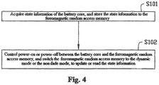
- Fig. 4 it is a schematic flow chart of a battery control method according to an embodiment of the present disclosure.
- the method according to the embodiment of the present disclosure can be specifically implemented through a control unit.
- the method includes: S101: The state information of the battery core 13 is acquired, and the state information is stored to the FRAM 174.
- the state information includes at least one of the followings: capacity of the battery core 13, voltage of the battery core 13, current of the battery core 13, or battery temperature of the battery core 13.
- S102 Power-on or power-off between the battery core 13 and the FRAM 174 is controlled, and the FRAM 174 is switched to the dynamic mode or the non-fade mode to update or read the state information.
- the battery 100 further includes a switch unit 171.
- the switch unit 171 is electrically connected with the battery core 13 and the FRAM 174.
- the battery core 13 has a power-on state and a power-off state.
- the control unit 173 stores the state information to the FRAM 174.
- the control unit 173 may acquire the state information from the FRAM 174.
- the battery 100 further includes a trigger key S.
- the trigger key S is used to control power-on or power-off of the battery core 13. For example, when the battery core 13 is in a power-on state, that is, the battery core 13 is supplying power to an external load, if a user presses down the trigger key S, the battery core 13 switches to a power-off state. When the battery core 13 is in a power-off state, that is, the battery core 13 stops supplying power to an external load, if the user presses down the trigger key S once again, the battery core 13 will switch to the power-on state. That is, the battery core 13 restores to supply power to an external load.
- the trigger key S is electrically connected with the control unit 173.
- the trigger key S is used to send a trigger signal to the control unit 173, and the control unit 173 controls switch-on and switch-off of the switch unit 171 in accordance with the trigger signal.
- the trigger key S may be electrically connected to the battery core 13. Therefore, when the trigger key S is triggered, the battery core 13 can temporarily supply power for the control unit 173 directly through the trigger key S.
- the battery 100 further includes a key power supply Vcc, and the key power supply Vcc is electrically connected with the trigger key S.
- the key power supply Vcc temporarily supplies power for the control unit 173 through the trigger key S.
- control circuit 17 further includes a charge and discharge connecting end 176, and the control unit 173 can control switch-on and switch-off between the FRAM 174 and the battery core 13 in accordance with switch-on and switch-off of the charge and discharge connecting end 176 and the external device.
- the aforementioned battery 100 may cut off the power supply of the control circuit 17 to reduce power consumption of the control circuit 17 to zero.
- the problem of overdischarge of the battery core 13 would not be a concern, and storage time of the battery 100 can be effectively extended.
- the control circuit 17 is provided with the FRAM 174. Therefore, even if the battery core 13 is in a power-off state, the FRAM 174 can still save data effectively to prevent information loss. That is to say, the control circuit 17 and the battery 100 having the control circuit 17 can effectively reduce power consumption, and can also effectively save data to prevent information loss.
Landscapes
- Engineering & Computer Science (AREA)
- Chemical & Material Sciences (AREA)
- Chemical Kinetics & Catalysis (AREA)
- Electrochemistry (AREA)
- General Chemical & Material Sciences (AREA)
- Manufacturing & Machinery (AREA)
- Microelectronics & Electronic Packaging (AREA)
- Power Engineering (AREA)
- Charge And Discharge Circuits For Batteries Or The Like (AREA)
- Secondary Cells (AREA)
Abstract
Description
- The present disclosure relates to a control circuit, a battery having the control circuit and a battery control method.
- At present, in terms of a battery on the market, it may be common to add a control circuit to a battery core to implement many circuit functions such as the minimum discharging voltage limit, the maximum charging voltage limit, and temperature and current detection of the battery core. However, when the battery core does not supply power to an external load, the control circuit is still in an operating state. For example, the control unit in the control circuit needs to monitor state information of the battery core regularly and store the state information to a register. When the battery core does not supply power to an external load, the control circuit may still generate corresponding power consumption, and at this point, the battery is still in a power consumption state.
- At present, a common solution is as follows: when the battery is in a power-off state, the control unit detects a voltage of the battery core, and, when the voltage of the battery core is lower than a preset value, sends a corresponding control instruction to cause the battery to enter into a low power consumption state. However, even if the battery enters into the low power consumption state, the battery core still needs to provide a corresponding power supply to maintain a state of the register inside the battery. That is, the battery core cannot completely cut off the power supply of the control circuit, and thus cannot completely put an end to loss of electricity.
- In view of the foregoing contents, it is necessary to provide a battery that can effectively put an end to loss of electricity and a control circuit thereof, and a battery control method.
- A control circuit for controlling a battery core, including:
- a power input end, the power input end being used to be electrically connected to the battery core to provide a power supply for the control circuit;
- a ferromagnetic random access memory, the ferromagnetic random access memory having a dynamic mode and a non-fade mode; and
- a control unit electrically connected with the ferromagnetic random access memory, the control unit being used to acquire state information of the battery core and store the state information to the ferromagnetic random access memory;
- wherein the control circuit switches on or switches off an electrical connection between the power input end and the battery core to switch the ferromagnetic random access memory to the dynamic mode or the non-fade mode.
- Further, the control unit is a Field-Programmable Gate Array (FPGA), a Micro-Controller Unit (MCU) with a control program embedded therein, or a single chip microcomputer.
- Further, the state information includes at least one of the followings: capacity of the battery core, voltage of the battery core, current of the battery core, or battery temperature of the battery core.
- Further, the control unit further includes a switch unit. The power input end is electrically connected to the battery core through the switch unit, and the control unit, by switching on or switching off the switch unit, switches on or switches off the electrical connection between the power input end and the battery core.
- Further, the switch unit is a Metal Oxide Semiconductor Field Effect Transistor, a relay, or a mechanical switch.
- Further, the control circuit further includes a trigger key, and the trigger key is used to control the battery core to be powered on or powered off.
- Further, when the battery core is controlled, through the trigger key, to switch to a power-off state, the control unit stores the state information to the ferromagnetic random access memory; and when the battery core is controlled, through the trigger key, to switch to a power-on state, the control unit acquires the state information from the ferromagnetic random access memory.
- Further, the trigger key is electrically connected with the control unit, the trigger key is used to send a trigger signal to the control unit, and the control unit controls switch-on and switch-off of the power input end and the battery core in accordance with the trigger signal.
- Further, the trigger key is electrically connected with the battery core, and when the trigger key is triggered, the battery core temporarily supplies power for the control unit through the trigger key.
- Further, the control circuit further includes a key power supply, the trigger key is electrically connected with the key power supply, and when the trigger key is triggered, the key power supply temporarily supplies power for the control unit through the trigger key.
- Further, the control circuit further includes a sensing circuit and a charge and discharge connecting end, the charge and discharge connecting end is electrically connected with the battery core through the sensing circuit, the sensing circuit is electrically connected with the control unit, and the sensing circuit is used to sense whether or not the charge and discharge connecting end is in electrical communication with an external device; when the sensing circuit senses that the charge and discharge connecting end is in electrical communication with the external device, the control unit switches on the electrical connection between the power input end and the battery core, and when the sensing circuit senses that the charge and discharge connecting end is out of electrical communication with the external device, the control unit switches off the electrical connection between the power input end and the battery core.
- Further, the control circuit further includes a charge and discharge protection circuit and a charge and discharge connecting end, the charge and discharge protection circuit is electrically connected to the control unit and the battery core, the battery core is charged or supplies power to an external load through the charge and discharge protection circuit, and the charge and discharge connecting end is electrically connected to the charge and discharge protection circuit and used to be electrically connected with an external device.
- Further, the charge and discharge protection circuit has a switch function, and the control unit controls power-on and power-off of the battery core with respect to the external device through the charge and discharge protection circuit.
- Further, the control circuit further includes a power supply switch, the power supply switch is electrically connected between the charge and discharge protection circuit and the battery core and is electrically connected with the control unit, and the control unit controls power-on and power-off of the battery core with respect to the external device through the power supply switch.
- Further, the control circuit further includes a charge and discharge protection circuit and a charge and discharge connecting end, the charge and discharge protection circuit is electrically connected to the control unit and the battery core, the battery core is charged or supplies power to an external load through the charge and discharge protection circuit, and the charge and discharge connecting end is electrically connected to the charge and discharge protection circuit and used to be electrically connected with an external device.
- Further, the charge and discharge protection circuit is electrically connected with the battery core through the switch unit, and the control unit controls power-on and power-off of the battery core with respect to the external device through the switch unit.
- Further, the control circuit further includes a signal interface, the signal interface is electrically connected to the control unit, and the control circuit is electrically connected to an external apparatus through the signal interface, so as to conduct data communication with the external apparatus.
- A battery, including a battery core and a control circuit for controlling the battery core, the control circuit including:
- a power input end, the power input end being used to be electrically connected to the battery core to provide a power supply for the control circuit;
- a ferromagnetic random access memory, the ferromagnetic random access memory having a dynamic mode and a non-fade mode; and
- a control unit electrically connected with the ferromagnetic random access memory, the control unit being used to acquire state information of the battery core and store the state information to the ferromagnetic random access memory;
- wherein the control circuit switches on or switches off an electrical connection between the power input end and the battery core to switch the ferromagnetic random access memory to the dynamic mode or the non-fade mode.
- Further, the battery further includes a housing, and both the battery core and the control circuit are disposed in the housing.
- Further, the control unit is a Field-Programmable Gate Array, a Micro-Controller Unit (MCU) with a control program embedded therein, or a single chip microcomputer.
- Further, the state information includes at least one of the followings: capacity of the battery core, voltage of the battery core, current of the battery core, or battery temperature of the battery core.
- Further, the control circuit further includes a switch unit. The power input end is electrically connected to the battery core through the switch unit, and the control unit, by switching on or switching off the switch unit, switches on or switches off the electrical connection between the power input end and the battery core.
- Further, the switch unit is a Metal Oxide Semiconductor Field Effect Transistor, a relay, or a mechanical switch.
- Further, the control circuit further includes a trigger key, and the trigger key is used to control the battery core to be powered on or powered off.
- Further, when the battery core is controlled, through the trigger key, to switch to a power-off state, the control unit stores the state information to the ferromagnetic random access memory; and when the battery core is controlled, through the trigger key, to switch to a power-on state, the control unit acquires the state information from the ferromagnetic random access memory.
- Further, the trigger key is electrically connected with the control unit, the trigger key is used to send a trigger signal to the control unit, and the control unit controls switch-on and switch-off of the power input end and the battery core in accordance with the trigger signal.
- Further, the trigger key is electrically connected with the battery core, and when the trigger key is triggered, the battery core temporarily supplies power for the control unit through the trigger key.
- Further, the control circuit further includes a key power supply, the trigger key is electrically connected with the key power supply, and when the trigger key is triggered, the key power supply temporarily supplies power for the control unit through the trigger key.
- Further, the control circuit further includes a sensing circuit and a charge and discharge connecting end, the charge and discharge connecting end is electrically connected with the battery core through the sensing circuit, the sensing circuit is electrically connected with the control unit, and the sensing circuit is used to sense whether or not the charge and discharge connecting end is in electrical communication with an external device; when the sensing circuit senses that the charge and discharge connecting end is in electrical communication with the external device, the control unit switches on the electrical connection between the power input end and the battery core, and when the sensing circuit senses that the charge and discharge connecting end is out of electrical communication with the external device, the control unit switches off the electrical connection between the power input end and the battery core.
- Further, the control circuit further includes a charge and discharge protection circuit and a charge and discharge connecting end, the charge and discharge protection circuit is electrically connected to the control unit and the battery core, the battery core is charged or supplies power to an external load through the charge and discharge protection circuit, and the charge and discharge connecting end is electrically connected to the charge and discharge protection circuit and used to be electrically connected with an external device.
- Further, the charge and discharge protection circuit has a switch function, and the control unit controls power-on and power-off of the battery core with respect to the external device through the charge and discharge protection circuit.
- Further, the control circuit further includes a power supply switch, the power supply switch is electrically connected between the charge and discharge protection circuit and the battery core and is electrically connected with the control unit, and the control unit controls power-on and power-off of the battery core with respect to the external device through the power supply switch.
- Further, the control circuit further includes a charge and discharge protection circuit and a charge and discharge connecting end, the charge and discharge protection circuit is electrically connected to the control unit and the battery core, the battery core is charged or supplies power to an external load through the charge and discharge protection circuit, and the charge and discharge connecting end is electrically connected to the charge and discharge protection circuit and used to be electrically connected with an external device.
- Further, the charge and discharge protection circuit is electrically connected with the battery core through the switch unit, and the control unit controls power-on and power-off of the battery core with respect to the external device through the switch unit.
- Further, the control circuit further includes a signal interface, the signal interface is electrically connected to the control unit, and the control circuit is electrically connected to an external apparatus through the signal interface, so as to conduct data communication with the external apparatus.
- A battery control method, the battery including a battery core and a ferromagnetic random access memory, and the ferromagnetic random access memory having a dynamic mode and a non-fade mode, the method includes:
- acquiring state information of the battery core, and storing the state information to the ferromagnetic random access memory; and
- controlling power-on or power-off between the battery core and the ferromagnetic random access memory, and switching the ferromagnetic random access memory to the dynamic mode or the non-fade mode to update or read the state information.
- Further, the state information includes at least one of the followings: capacity of the battery core, voltage of the battery core, current of the battery core, or battery temperature of the battery core.
- Further, the battery further includes a switch unit, and by switching on or switching off the switch unit, an electrical connection between the ferromagnetic random access memory and the battery core is switched on or switched off.
- Further, when the battery core is switched to a power-off state, the state information is stored to the ferromagnetic random access memory; and when the battery core is switched to a power-on state, the state information is acquired from the ferromagnetic random access memory.
- Further, when a trigger signal is received, switch-on and switch-off between the ferromagnetic random access memory and the battery core are controlled in accordance with the trigger signal.
- Further, when a trigger signal is received, the battery core is controlled to supply power for the ferromagnetic random access memory.
- Further, the battery further includes a key power supply, and when a trigger signal is received, the key power supply is controlled to supply power for the ferromagnetic random access memory.
- Further, the control circuit further includes a charge and discharge connecting end, and switch-on and switch-off between the ferromagnetic random access memory and the battery core are controlled in accordance with switch-on and switch-off of the charge and discharge connecting end and an external device.
- The aforementioned battery can effectively cut off the power supply of the control circuit to reduce power consumption of the control circuit to zero. The problem of overdischarge of the battery core would not be a concern, and storage time of the battery can be effectively extended. At the same time, the control circuit is further provided with the ferromagnetic random access memory. Therefore, even if the battery core is in a power-off state, the ferromagnetic random access memory can still save data effectively to prevent information loss. That is, the aforementioned control circuit and the battery having the control circuit can effectively reduce power consumption, and can also effectively save data to prevent information loss.
-
-
Fig. 1 is a schematic structural diagram of a battery according to an embodiment of the present disclosure. -
Fig. 2 is one functional module diagram of the battery shown inFig. 1 . -
Fig. 3 is another functional module diagram of the battery shown inFig. 1 . -
Fig. 4 is a schematic flow chart of a battery control method according to an embodiment of the present disclosure. -
Battery 100 Housing 11 Battery core 13 Control circuit 17 Switch unit 171 Power input end 172 Control unit 173 FRAM 174 Trigger key s Charge and discharge protection circuit 175 Charge and discharge connecting end 176 Signal interface 178 Sensing circuit 179 Power supply switch sw Key power supply Vcc - The following DETAILED DESCRIPTION OF THE DISCLOSURE further describes the present disclosure with reference to the aforementioned accompanying drawings.
- The technical solution in embodiments of the present disclosure will be clearly and completely described below with reference to the accompanying drawings of the embodiments of the present disclosure. Apparently, the described embodiments are merely some of the embodiments of the present disclosure rather than all of the embodiments. All other embodiments obtained by a person of ordinary skill in the art based on the embodiments of the present disclosure without creative efforts shall fall within the protection scope of the present disclosure.
- It should be noted that, when one element is referred to as "electrically connect" another element, it may be directly on another assembly or it is also possible that there is an element between them. When one element is considered to "electrically connect" another element, it may be a contact connection. For example, it may be a wire connection manner, and it may also be a non-contact connection. For example, it may be a non-contact coupling manner.
- Unless otherwise defined, all the technical and scientific terms used herein are the same as the meanings generally understood by technicians belonging to the technical field of the present disclosure. Herein, the terms used in the specification of the present disclosure are merely intended to describe specific embodiments, instead of limiting the present disclosure. The term "and/or" used herein includes any combination and all combinations of one or more related items listed.
- Some implementation manners of the present disclosure are described below in detail with reference to the accompanying drawings. In the event of no conflict, embodiments described below and features in the embodiments can be combined with each other.
- Referring to
Fig. 1 , a preferred embodiment of the present disclosure provides abattery 100, including ahousing 11, abattery core 13, and acontrol circuit 17. Thebattery core 13 and thecontrol circuit 17 are both disposed in thehousing 11. Thecontrol circuit 17 is provided thereon with aswitch unit 171, and theswitch unit 171 is electrically connected to thebattery core 13. Thebattery 100, by controlling switch-on and switch-off of theswitch unit 171, causes thebattery core 13 and thecontrol circuit 17 to establish an electrical connection therebetween or to be disconnected from each other, and then causes thebattery core 13, through theswitch unit 171, to provide a power supply for thecontrol circuit 17 or cut off power supply for thecontrol circuit 17. - The
switch unit 171 may be a Metal Oxide Semiconductor Field Effect Transistor (MOS transistor), or other electronic switches such as a relay and a mechanical switch. In this embodiment, theswitch unit 171 is a MOS transistor. - The
control circuit 17 may include one or more circuit boards, or include one or more microprocessors. Referring toFig. 2 together, specifically, thecontrol circuit 17 further includes apower input end 172, acontrol unit 173, a Ferromagnetic Random Access Memory (FRAM) 174, and a trigger key S. Both thecontrol unit 173 and theFRAM 174 are electrically connected to thepower input end 172. - The
power input end 172 is electrically connected to an anode and a cathode of thebattery core 13 through theswitch unit 171 to receive electric energy output by thebattery core 13, and then serves as a power supply of thecontrol circuit 17 to supply power for operation of thecontrol unit 173 and theFRAM 174. - The
control unit 173 may be a FieldTProgrammable Gate Array (FPGA), a Micro-Controller Unit (MCU) with a control program embedded therein, or a single chip microcomputer and the like. In this embodiment, thecontrol unit 173 is an MCU. - The
FRAM 174 is electrically connected to thecontrol unit 173 and used to store state information of the battery and factory information such as model of the battery core, chemical properties of the battery core, production date of the battery, serial number of the battery, and manufacturer of the battery. State information of thebattery core 13 at least includes current capacity of thebattery core 13, current voltage of thebattery core 13, current current of thebattery core 13, current battery temperature of thebattery core 13, and other parameters. TheFRAM 174 has advantages of a fast read and write speed and non-volatility, and can achieve that the current state is rapidly saved when the battery is shut down and, in the event of boot, the state prior to the last power-off is rapidly restored. - In this embodiment, the
FRAM 174 may convert between a dynamic mode and a non-fade mode. When operating in the dynamic mode, theFRAM 174 obtains a high dielectric constant due to a special memory structure, and then can be used as an ordinary Dynamic Random Access Memory (DRAM). When operating in the non-fade mode, theFRAM 174, due to a stable state achieved by polarization, can also save data effectively even if without power. That is to say, even if theswitch unit 171 is disconnected to cause thebattery core 13 to stop supplying power for thecontrol circuit 17, theFRAM 174 can still effectively operate and has a non-fade characteristic. - Further, when the
switch unit 171 between thebattery core 13 and thecontrol circuit 17 is switched on to cause thebattery core 13 to be electrically connected with thecontrol circuit 17, thebattery core 13 provides a power supply for thecontrol circuit 17, and at this point, theFRAM 174 operates in the dynamic mode. Thecontrol unit 173 may perform a read/write operation on theFRAM 174. For example, the state information of thebattery core 13 is stored to theFRAM 174. When theswitch unit 171 between thebattery core 13 and thecontrol circuit 17 is switched off to cause thebattery core 13 to be disconnected from thecontrol circuit 17, thebattery core 13 stops supplying power for thecontrol circuit 17, and theFRAM 174 switches to the non-fade mode. At this point, theFRAM 174 can still effectively save the data stored to theFRAM 174 by thecontrol unit 173 to prevent loss of the data. - The trigger key S is used to control the
battery core 13 to be powered on or powered off. For example, when thebattery core 13 is in a power-on state, that is, thebattery core 13 is supplying power to an external load, if a user presses down the trigger key S, thebattery core 13 switches to a power-off state. When thebattery core 13 is in a power-off state, that is, thebattery core 13 stops supplying power to an external load, if the user presses down the trigger key S once again, thebattery core 13 will switch to the power-on state. That is, thebattery core 13 restores to supply power to an external load. Furthermore, the trigger key S is electrically connected with thecontrol unit 173. The trigger key S is used to send a trigger signal to thecontrol unit 173, and thecontrol unit 173 controls switch-on and switch-off of theswitch unit 171 in accordance with the trigger signal. - In this embodiment, the
control circuit 17 further includes a key power supply Vcc. The trigger key S is electrically connected with the key power supply Vcc. When the trigger key S controls thebattery core 13 to switch to a power-off state, the key power supply Vcc temporarily supplies power for thecontrol unit 173 through the trigger key S. At this point, thecontrol unit 173 stores the current state information to theFRAM 174, and controls theswitch unit 171 to switch off to cause thebattery core 13 to disconnect the electrical connection with thecontrol circuit 17. That is, thebattery core 13 cuts off the power supply of thecontrol circuit 17 to cause power consumption of thecontrol circuit 17 to be zero, thereby effectively extending storage life of thebattery 100. When thebattery core 13 is controlled, through the trigger key S, to switch to the power-on state, the key power supply Vcc temporarily supplies power for thecontrol unit 173 through the trigger key S. At this point, thecontrol unit 173 controls theswitch unit 171 to switch on, so as to establish an electrical connection between thebattery core 13 and thecontrol circuit 17 to cause thebattery core 13 to continue to supply power for thecontrol circuit 17. At the same time, theFRAM 174 switches to the dynamic mode once again to facilitate thecontrol unit 173 to perform the read/write operation on theFRAM 174. That is, thecontrol circuit 17 can resume normal work, and continue to operate in accordance with the state before the last shutdown. - It can be understood that, in other embodiments, the key power supply Vcc may also be omitted and the trigger key S is directly electrically connected to the
battery core 13. At this point, when the trigger key S is triggered, thebattery core 13 may temporarily supply power for thecontrol unit 173 directly through the trigger key S. - It can be understood that the
control circuit 17 further includes a charge anddischarge protection circuit 175 and a charge and discharge connectingend 176. The charge anddischarge protection circuit 175 is electrically connected to thecontrol unit 173. Thebattery core 13 may be charged or supply power to an external load through the charge anddischarge protection circuit 175. The charge and discharge connectingend 176 is electrically connected to the charge anddischarge protection circuit 175 and used to be electrically connected with an external device (not shown) to provide charge and discharge interfaces of thebattery 100. For example, when thebattery core 13 is electrically connected to the external device through the charge and discharge connectingend 176, the external device can charge thebattery 100 through the charge and discharge connectingend 176. - In this embodiment, the
control circuit 17 further includes a power supply switch SW. The power supply switch SW is electrically connected between the charge anddischarge protection circuit 175 and thebattery core 13, and is electrically connected with thecontrol unit 173. Thecontrol unit 173 controls power-on and power-off of thebattery core 13 with respect to the charge anddischarge protection circuit 175 through the power supply switch SW, and then controls power-on and power-off of thebattery core 13 with respect to the external device through the charge anddischarge protection circuit 175. - It can be understood that, in other embodiments, the
control circuit 17 may also not be provided with a separate power supply switch SW, but causes the charge anddischarge protection circuit 175 to be electrically connected with thebattery core 13 through theswitch unit 171. In this way, thecontrol unit 173 controls power-on and power-off of thebattery core 13 with respect to the charge anddischarge protection circuit 175 through theswitch unit 171, and then controls power-on and power-off of thebattery core 13 with respect to the external device through the charge anddischarge protection circuit 175. Certainly, in other embodiments, when the charge anddischarge protection circuit 175 per se has a switch function, the charge anddischarge protection circuit 175 can directly electrically connect with respect to thecontrol unit 173 and thebattery core 13. In this way, thecontrol unit 173 can control power-on and power-off of thebattery core 13 with respect to the charge anddischarge protection circuit 175 through opening and closing of the charge anddischarge protection circuit 175, and then control power-on and power-off of thebattery core 13 with respect to the external device through the charge anddischarge protection circuit 175. - It can be understood that the
control circuit 17 further includes asignal interface 178, and thesignal interface 178 is electrically connected with thecontrol unit 173 and used to establish an electrical connection between thecontrol circuit 17 and another external apparatus, for example, an unmanned aerial vehicle, so as to enable the external apparatus to conduct data communication with thecontrol circuit 17. - It can be understood that, when the
battery core 13 is in the power-on state, thecontrol circuit 17 operates normally. At this point, theFRAM 174 in thecontrol circuit 17 operates in the dynamic mode, and thecontrol unit 173 can acquire the state information of thebattery core 13 regularly or in real time and write the acquired state information into theFRAM 174. If, at this point, the user presses down the trigger key S, thebattery core 13 switches to the power-off state. At this point, thebattery core 13 or the key power supply Vcc temporarily supplies power for thecontrol unit 173 through the trigger key S, and thecontrol unit 173 acquires the state information of thebattery core 13 and stores the state information to theFRAM 174. Next, thecontrol unit 173 switches off theswitch unit 171 to cause thebattery core 13 to disconnect the electrical connection with thecontrol circuit 17. That is, thebattery core 13 cuts off the power supply of thecontrol circuit 17. At this point, thecontrol circuit 17 stops operating to cause power consumption thereof to be zero, thereby effectively extending storage life of thebattery 100. In addition, when thebattery core 13 cuts off the power supply of thecontrol circuit 17, theFRAM 174 switches to the non-fade mode. Therefore, even if thebattery core 13 is disconnected from thecontrol circuit 17, theFRAM 174 can still effectively save the state information of thebattery core 13 to prevent loss of the data. - Alternatively, when the
control unit 173 is a mechanical switch, if, at this point, the user presses down the mechanical switch, thebattery core 13 switches to the power-off state, and theFRAM 174 saves the state information of thebattery core 13 prior to the power-off. - When the
battery core 13 is in the power-off state and the user presses down the trigger key S once again, thebattery core 13 switches to the power-on state. At this point, thebattery core 13 or the key power supply Vcc temporarily supplies power for thecontrol unit 173 through the trigger key S. Thecontrol unit 173 controls theswitch unit 171 to switch on, and then establishes an electrical connection between thebattery core 13 and thecontrol circuit 17 to cause thebattery core 13 to continue to supply power for thecontrol circuit 17. At the same time, theFRAM 174 switches to the dynamic mode once again to facilitate thecontrol unit 173 to perform the read/write operation on theFRAM 174. In this way, thecontrol circuit 17 can continue to operate in accordance with the state before the last shutdown. - Referring to
Fig. 3 together, it can be understood that, in other embodiments, the trigger key S may be omitted. At this point, thecontrol circuit 17 includes asensing circuit 179. The charge and discharge connectingend 176 is electrically connected with thebattery core 13 through thesensing circuit 179. Thesensing circuit 178 is further electrically connected with thecontrol unit 173 and used to sense whether or not the charge and discharge connectingend 176 is in electrical communication with an external device. When thesensing circuit 178 senses that the charge and discharge connectingend 176 is in electrical communication with the external device, thecontrol unit 173 controls theswitch unit 171 to switch on. When thesensing circuit 178 senses that the charge and discharge connectingend 176 is out of electrical communication with the external device, thecontrol unit 173 controls theswitch unit 171 to switch off. - Specifically, referring to
Fig. 4 , it is a schematic flow chart of a battery control method according to an embodiment of the present disclosure. The method according to the embodiment of the present disclosure can be specifically implemented through a control unit. Specifically, the method includes:
S101: The state information of thebattery core 13 is acquired, and the state information is stored to theFRAM 174. - Wherein the state information includes at least one of the followings: capacity of the
battery core 13, voltage of thebattery core 13, current of thebattery core 13, or battery temperature of thebattery core 13. - S102: Power-on or power-off between the
battery core 13 and theFRAM 174 is controlled, and theFRAM 174 is switched to the dynamic mode or the non-fade mode to update or read the state information. - Further, the
battery 100 further includes aswitch unit 171. Theswitch unit 171 is electrically connected with thebattery core 13 and theFRAM 174. Thecontrol unit 173, by switching on or switching off theswitch unit 171, switches on or switches off the electrical connection between theFRAM 174 and thebattery core 13. - It can be understood that the
battery core 13 has a power-on state and a power-off state. When thebattery core 13 is switched to the power-off state, thecontrol unit 173 stores the state information to theFRAM 174. When thebattery core 13 switches to the power-on state, thecontrol unit 173 may acquire the state information from theFRAM 174. - It can be understood that the
battery 100 further includes a trigger key S. The trigger key S is used to control power-on or power-off of thebattery core 13. For example, when thebattery core 13 is in a power-on state, that is, thebattery core 13 is supplying power to an external load, if a user presses down the trigger key S, thebattery core 13 switches to a power-off state. When thebattery core 13 is in a power-off state, that is, thebattery core 13 stops supplying power to an external load, if the user presses down the trigger key S once again, thebattery core 13 will switch to the power-on state. That is, thebattery core 13 restores to supply power to an external load. - Furthermore, the trigger key S is electrically connected with the
control unit 173. The trigger key S is used to send a trigger signal to thecontrol unit 173, and thecontrol unit 173 controls switch-on and switch-off of theswitch unit 171 in accordance with the trigger signal. - Furthermore, the trigger key S may be electrically connected to the
battery core 13. Therefore, when the trigger key S is triggered, thebattery core 13 can temporarily supply power for thecontrol unit 173 directly through the trigger key S. - Furthermore, the
battery 100 further includes a key power supply Vcc, and the key power supply Vcc is electrically connected with the trigger key S. The key power supply Vcc temporarily supplies power for thecontrol unit 173 through the trigger key S. - Furthermore, the
control circuit 17 further includes a charge and discharge connectingend 176, and thecontrol unit 173 can control switch-on and switch-off between theFRAM 174 and thebattery core 13 in accordance with switch-on and switch-off of the charge and discharge connectingend 176 and the external device. - The
aforementioned battery 100 may cut off the power supply of thecontrol circuit 17 to reduce power consumption of thecontrol circuit 17 to zero. The problem of overdischarge of thebattery core 13 would not be a concern, and storage time of thebattery 100 can be effectively extended. At the same time, thecontrol circuit 17 is provided with theFRAM 174. Therefore, even if thebattery core 13 is in a power-off state, theFRAM 174 can still save data effectively to prevent information loss. That is to say, thecontrol circuit 17 and thebattery 100 having thecontrol circuit 17 can effectively reduce power consumption, and can also effectively save data to prevent information loss. - The above descriptions are merely embodiments of the present disclosure, but are not intended to limit the patent scope of the present disclosure. Any equivalent structure or equivalent process variation made by using contents of the specification and the drawings of the present disclosure, or directly or indirectly applied to other related technical fields, should be likewise included in the patent protection scope of the present disclosure.
Claims (43)
- A control circuit for controlling a battery core, comprising:a power input end, the power input end being used to be electrically connected to the battery core to provide a power supply for the control circuit;a ferromagnetic random access memory, the ferromagnetic random access memory having a dynamic mode and a non-fade mode; anda control unit electrically connected with the ferromagnetic random access memory, the control unit being used to acquire state information of the battery core and store the state information to the ferromagnetic random access memory;wherein the control circuit switches on or switches off an electrical connection between the power input end and the battery core to switch the ferromagnetic random access memory to the dynamic mode or the non-fade mode.
- The control circuit as recited in claim 1, wherein the control unit is a Field-Programmable Gate Array (FPGA), a Micro-Controller Unit (MCU) with a control program embedded therein, or a single chip microcomputer.
- The control circuit as recited in claim 1, wherein the state information comprises at least one of the followings: capacity of the battery core, voltage of the battery core, current of the battery core, or battery temperature of the battery core.
- The control circuit as recited in claim 1, wherein the control circuit further comprises a switch unit, the power input end is electrically connected to the battery core through the switch unit, and the control unit, by switching on or switching off the switch unit, switches on or switches off the electrical connection between the power input end and the battery core.
- The control circuit as recited in claim 4, wherein the switch unit is a Metal Oxide Semiconductor Field Effect Transistor, a relay, or a mechanical switch.
- The control circuit as recited in claim 1, wherein the control circuit further comprises a trigger key, and the trigger key is used to control the battery core to be powered on or powered off.
- The control circuit as recited in claim 6, wherein, when the battery core is controlled, through the trigger key, to switch to a power-off state, the control unit stores the state information to the ferromagnetic random access memory; and when the battery core is controlled, through the trigger key, to switch to a power-on state, the control unit acquires the state information from the ferromagnetic random access memory.
- The control circuit as recited in claim 6, wherein the trigger key is electrically connected with the control unit, the trigger key is used to send a trigger signal to the control unit, and the control unit controls switch-on and switch-off of the power input end and the battery core in accordance with the trigger signal.
- The control circuit as recited in claim 6, wherein the trigger key is electrically connected with the battery core, and when the trigger key is triggered, the battery core temporarily supplies power for the control unit through the trigger key.
- The control circuit as recited in claim 6, wherein the control circuit further comprises a key power supply, the trigger key is electrically connected with the key power supply, and when the trigger key is triggered, the key power supply temporarily supplies power for the control unit through the trigger key.
- The control circuit as recited in claim 1, wherein the control circuit further comprises a sensing circuit and a charge and discharge connecting end, the charge and discharge connecting end is electrically connected with the battery core through the sensing circuit, the sensing circuit is electrically connected with the control unit, and the sensing circuit is used to sense whether or not the charge and discharge connecting end is in electrical communication with an external device; when the sensing circuit senses that the charge and discharge connecting end is in electrical communication with the external device, the control unit switches on the electrical connection between the power input end and the battery core, and when the sensing circuit senses that the charge and discharge connecting end is out of electrical communication with the external device, the control unit switches off the electrical connection between the power input end and the battery core.
- The control circuit as recited in claim 1, wherein the control circuit further comprises a charge and discharge protection circuit and a charge and discharge connecting end, the charge and discharge protection circuit is electrically connected to the control unit and the battery core, the battery core is charged or supplies power to an external load through the charge and discharge protection circuit, and the charge and discharge connecting end is electrically connected to the charge and discharge protection circuit and used to be electrically connected with an external device.
- The control circuit as recited in claim 12, wherein the charge and discharge protection circuit has a switch function, and the control unit controls power-on and power-off of the battery core with respect to the external device through the charge and discharge protection circuit.
- The control circuit as recited in claim 12, wherein the control circuit further comprises a power supply switch, the power supply switch is electrically connected between the charge and discharge protection circuit and the battery core and is electrically connected with the control unit, and the control unit controls power-on and power-off of the battery core with respect to the external device through the power supply switch.
- The control circuit as recited in claim 4, wherein the control circuit further comprises a charge and discharge protection circuit and a charge and discharge connecting end, the charge and discharge protection circuit is electrically connected to the control unit and the battery core, the battery core is charged or supplies power to an external load through the charge and discharge protection circuit, and the charge and discharge connecting end is electrically connected to the charge and discharge protection circuit and used to be electrically connected with an external device.
- The control circuit as recited in claim 15, wherein the charge and discharge protection circuit is electrically connected with the battery core through the switch unit, and the control unit controls power-on and power-off of the battery core with respect to the external device through the switch unit.
- The control circuit as recited in claim 1, wherein the control circuit further comprises a signal interface, the signal interface is electrically connected to the control unit, and the control circuit is electrically connected to an external apparatus through the signal interface, so as to conduct data communication with the external apparatus.
- A battery, comprising a battery core and a control circuit for controlling the battery core, the control circuit comprising:a power input end, the power input end being used to be electrically connected to the battery core to provide a power supply for the control circuit;a ferromagnetic random access memory, the ferromagnetic random access memory having a dynamic mode and a non-fade mode; anda control unit electrically connected with the ferromagnetic random access memory, the control unit being used to acquire state information of the battery core and store the state information to the ferromagnetic random access memory;wherein the control circuit switches on or switches off an electrical connection between the power input end and the battery core to switch the ferromagnetic random access memory to the dynamic mode or the non-fade mode.
- The battery as recited in claim 18, wherein the battery further comprises a housing, and both the battery core and the control circuit are disposed in the housing.
- The battery as recited in claim 18, wherein the control unit is a Field-Programmable Gate Array (FPGA), a Micro-Controller Unit (MCU) with a control program embedded therein, or a single chip microcomputer.
- The battery as recited in claim 18, wherein the state information comprises at least one of the followings: capacity of the battery core, voltage of the battery core, current of the battery core, or battery temperature of the battery core.
- The battery as recited in claim 18, wherein the control circuit further comprises a switch unit, the power input end is electrically connected to the battery core through the switch unit, and the control unit, by switching on or switching off the switch unit, switches on or switches off the electrical connection between the power input end and the battery core.
- The battery as recited in claim 22, wherein the switch unit is a Metal Oxide Semiconductor Field Effect Transistor, a relay, or a mechanical switch.
- The battery as recited in claim 18, wherein the control circuit further comprises a trigger key, and the trigger key is used to control the battery core to be powered on or powered off.
- The battery as recited in claim 24, wherein, when the battery core is controlled, through the trigger key, to switch to a power-off state, the control unit stores the state information to the ferromagnetic random access memory; and when the battery core is controlled, through the trigger key, to switch to a power-on state, the control unit acquires the state information from the ferromagnetic random access memory.
- The battery as recited in claim 24, wherein the trigger key is electrically connected with the control unit, the trigger key is used to send a trigger signal to the control unit, and the control unit controls switch-on and switch-off of the power input end and the battery core in accordance with the trigger signal.
- The battery as recited in claim 24, wherein the trigger key is electrically connected with the battery core, and when the trigger key is triggered, the battery core temporarily supplies power for the control unit through the trigger key.
- The battery as recited in claim 24, wherein the control circuit further comprises a key power supply, the trigger key is electrically connected with the key power supply, and when the trigger key is triggered, the key power supply temporarily supplies power for the control unit through the trigger key.
- The battery as recited in claim 18, wherein the control circuit further comprises a sensing circuit and a charge and discharge connecting end, the charge and discharge connecting end is electrically connected with the battery core through the sensing circuit, the sensing circuit is electrically connected with the control unit, and the sensing circuit is used to sense whether or not the charge and discharge connecting end is in electrical communication with an external device; when the sensing circuit senses that the charge and discharge connecting end is in electrical communication with the external device, the control unit switches on the electrical connection between the power input end and the battery core, and when the sensing circuit senses that the charge and discharge connecting end is out of electrical communication with the external device, the control unit switches off the electrical connection between the power input end and the battery core.
- The battery as recited in claim 18, wherein the control circuit further comprises a charge and discharge protection circuit and a charge and discharge connecting end, the charge and discharge protection circuit is electrically connected to the control unit and the battery core, the battery core is charged or supplies power to an external load through the charge and discharge protection circuit, and the charge and discharge connecting end is electrically connected to the charge and discharge protection circuit and used to be electrically connected with an external device.
- The battery as recited in claim 30, wherein the charge and discharge protection circuit has a switch function, and the control unit controls power-on and power-off of the battery core with respect to the external device through the charge and discharge protection circuit.
- The battery as recited in claim 30, wherein the control circuit further comprises a power supply switch, the power supply switch is electrically connected between the charge and discharge protection circuit and the battery core and is electrically connected with the control unit, and the control unit controls power-on and power-off of the battery core with respect to the external device through the power supply switch.
- The battery as recited in claim 22, wherein the control circuit further comprises a charge and discharge protection circuit and a charge and discharge connecting end, the charge and discharge protection circuit is electrically connected to the control unit and the battery core, the battery core is charged or supplies power to an external load through the charge and discharge protection circuit, and the charge and discharge connecting end is electrically connected to the charge and discharge protection circuit and used to be electrically connected with an external device.
- The battery as recited in claim 33, wherein the charge and discharge protection circuit is electrically connected with the battery core through the switch unit, and the control unit controls power-on and power-off of the battery core with respect to the external device through the switch unit.
- The battery as recited in claim 18, wherein the control circuit further comprises a signal interface, the signal interface is electrically connected to the control unit, and the control circuit is electrically connected to an external apparatus through the signal interface, so as to conduct data communication with the external apparatus.
- A battery control method, the battery comprising a battery core and a ferromagnetic random access memory, and the ferromagnetic random access memory having a dynamic mode and a non-fade mode, wherein the method comprises:acquiring state information of the battery core, and storing the state information to the ferromagnetic random access memory; andcontrolling power-on or power-off between the battery core and the ferromagnetic random access memory, and switching the ferromagnetic random access memory to the dynamic mode or the non-fade mode to update or read the state information.
- The battery control method as recited in claim 36, wherein the state information comprises at least one of the followings: capacity of the battery core, voltage of the battery core, current of the battery core, or battery temperature of the battery core.
- The battery control method as recited in claim 36, wherein the battery further comprises a switch unit, and by switching on or switching off the switch unit, an electrical connection between the ferromagnetic random access memory and the battery core is switched on or switched off.
- The battery control method as recited in claim 36, wherein, when the battery core is switched to a power-off state, the state information is stored to the ferromagnetic random access memory; and when the battery core is switched to a power-on state, the state information is acquired from the ferromagnetic random access memory.
- The battery control method as recited in claim 36, wherein, when a trigger signal is received, switch-on and switch-off between the ferromagnetic random access memory and the battery core are controlled in accordance with the trigger signal.
- The battery control method as recited in claim 36, wherein, when a trigger signal is received, the battery core is controlled to supply power for the ferromagnetic random access memory.
- The battery control method as recited in claim 36, wherein the battery further comprises a key power supply, and when a trigger signal is received, the key power supply is controlled to supply power for the ferromagnetic random access memory.
- The battery control method as recited in claim 36, wherein the control circuit further comprises a charge and discharge connecting end, and switch-on and switch-off between the ferromagnetic random access memory and the battery core are controlled in accordance with switch-on and switch-off of the charge and discharge connecting end and an external device.
Applications Claiming Priority (1)
| Application Number | Priority Date | Filing Date | Title |
|---|---|---|---|
| PCT/CN2015/082608 WO2017000103A1 (en) | 2015-06-29 | 2015-06-29 | Control circuit, battery provided with control circuit and battery control method |
Publications (2)
| Publication Number | Publication Date |
|---|---|
| EP3316383A1 true EP3316383A1 (en) | 2018-05-02 |
| EP3316383A4 EP3316383A4 (en) | 2018-06-06 |
Family
ID=55888361
Family Applications (1)
| Application Number | Title | Priority Date | Filing Date |
|---|---|---|---|
| EP15896634.1A Withdrawn EP3316383A4 (en) | 2015-06-29 | 2015-06-29 | Control circuit, battery provided with control circuit and battery control method |
Country Status (5)
| Country | Link |
|---|---|
| US (1) | US11139511B2 (en) |
| EP (1) | EP3316383A4 (en) |
| JP (1) | JP6379203B2 (en) |
| CN (2) | CN107769317B (en) |
| WO (1) | WO2017000103A1 (en) |
Families Citing this family (6)
| Publication number | Priority date | Publication date | Assignee | Title |
|---|---|---|---|---|
| WO2017000216A1 (en) * | 2015-06-30 | 2017-01-05 | 深圳市大疆创新科技有限公司 | Charging control circuit, charging device, charging system and charging control method |
| CN106716161B (en) * | 2016-10-28 | 2020-08-04 | 深圳市大疆创新科技有限公司 | Battery control method and system and battery |
| JP6916639B2 (en) * | 2017-03-13 | 2021-08-11 | エイブリック株式会社 | Charge / discharge control circuit and battery device |
| CN107732340B (en) * | 2017-10-27 | 2019-11-08 | 宁波三星医疗电气股份有限公司 | A kind of clock restorative procedure based on intelligent power terminal clock battery undervoltage |
| CN110622386B (en) * | 2018-02-28 | 2023-09-12 | 深圳市大疆创新科技有限公司 | Battery control circuit, power supply control system and movable platform |
| WO2022193965A1 (en) * | 2021-03-18 | 2022-09-22 | 浙江铅锂智行科技有限公司 | Electric vehicle |
Family Cites Families (32)
| Publication number | Priority date | Publication date | Assignee | Title |
|---|---|---|---|---|
| US3858184A (en) * | 1973-01-22 | 1974-12-31 | Monolithic Syst Corp | Automatic non-interrupting refresh technique |
| AU559311B2 (en) * | 1984-02-15 | 1987-03-05 | Matsushita Electric Industrial Co., Ltd. | Pay tv charge/time data display |
| JPH0681425B2 (en) * | 1990-03-31 | 1994-10-12 | アントン/バウエル インコーポレーテッド | Battery system method and device and battery pack |
| JPH06302179A (en) * | 1993-04-13 | 1994-10-28 | Casio Comput Co Ltd | Electronic equipment |
| US5710931A (en) * | 1994-09-07 | 1998-01-20 | Canon Kabushiki Kaisha | Suspension state control for information processing devices such as battery powered computers |
| KR970010634B1 (en) * | 1994-10-25 | 1997-06-28 | 삼성전자 주식회사 | Metwork hibernation system |
| KR0172003B1 (en) * | 1995-03-28 | 1999-03-30 | 김광호 | Computer system and its control method |
| US6228519B1 (en) * | 1997-10-06 | 2001-05-08 | Reveo, Inc. | Metal-air fuel cell battery systems having mechanism for extending the path length of metal-fuel tape during discharging and recharging modes of operation |
| JP4013003B2 (en) * | 1998-03-27 | 2007-11-28 | 宇部興産株式会社 | battery pack |
| JP3366568B2 (en) * | 1998-03-31 | 2003-01-14 | 宮田工業株式会社 | Battery charger |
| JP2001155781A (en) * | 1999-11-24 | 2001-06-08 | Toshiba Battery Co Ltd | Secondary battery device |
| CN1307260A (en) * | 2000-01-25 | 2001-08-08 | 睿阳科技股份有限公司 | UPS device and method capable of storing data automatically |
| JP3638109B2 (en) * | 2000-02-07 | 2005-04-13 | Necトーキン栃木株式会社 | Battery pack |
| JP2003180038A (en) * | 2001-12-11 | 2003-06-27 | Rohm Co Ltd | Charge controller |
| DE10206485B4 (en) * | 2002-02-16 | 2007-06-21 | Robert Bosch Gmbh | Power supply and electrical appliance |
| CN1236400C (en) * | 2002-02-27 | 2006-01-11 | 合邦电子股份有限公司 | Intelligent secondary battery managing method and device |
| JP2006260981A (en) * | 2005-03-17 | 2006-09-28 | Shin Kobe Electric Mach Co Ltd | Battery controller |
| CN200979994Y (en) * | 2006-06-30 | 2007-11-21 | 宁波力达物料搬运设备厂 | A storage battery charger |
| JP4973112B2 (en) * | 2006-10-06 | 2012-07-11 | パナソニック株式会社 | A system comprising a charging device and a storage battery state detection device |
| JP2009063502A (en) * | 2007-09-07 | 2009-03-26 | Seiko Epson Corp | Battery remaining capacity management system and its control method |
| US7813169B2 (en) * | 2008-01-18 | 2010-10-12 | Qimonda Flash Gmbh | Integrated circuit and method to operate an integrated circuit |
| JP2011182592A (en) * | 2010-03-02 | 2011-09-15 | Sanyo Electric Co Ltd | Battery pack |
| JP2011188570A (en) * | 2010-03-05 | 2011-09-22 | Toyota Motor Corp | Apparatus and method for power supply control |
| CN102447277A (en) * | 2010-10-14 | 2012-05-09 | 和映科技有限公司 | Battery module and method for recording signals of battery module |
| CN201821142U (en) * | 2010-10-21 | 2011-05-04 | 艾利和电子科技(中国)有限公司 | Portable electronic product power supply system |
| JP2012168728A (en) * | 2011-02-14 | 2012-09-06 | Mitsumi Electric Co Ltd | Protection module and state information management method in protection module |
| JP2012221854A (en) * | 2011-04-12 | 2012-11-12 | Sanyo Electric Co Ltd | Battery pack with output connector |
| US8878495B2 (en) * | 2011-08-31 | 2014-11-04 | GM Global Technology Operations LLC | Systems and methods for providing power to a load based upon a control strategy |
| US9883603B2 (en) * | 2013-07-16 | 2018-01-30 | Texas Instruments Incorporated | Electronic pull tab for battery protection |
| CN107742915B (en) * | 2013-12-06 | 2021-02-19 | 深圳市大疆创新科技有限公司 | Battery and aircraft with same |
| US10491014B2 (en) * | 2014-07-15 | 2019-11-26 | Dell Products, L.P. | Battery management system and method for extending time until a battery reaches an over-discharged state during storage of an information handling system |
| CN204696765U (en) * | 2015-06-29 | 2015-10-07 | 深圳市大疆创新科技有限公司 | Battery |
-
2015
- 2015-06-29 CN CN201711072206.5A patent/CN107769317B/en active Active
- 2015-06-29 WO PCT/CN2015/082608 patent/WO2017000103A1/en active Application Filing
- 2015-06-29 EP EP15896634.1A patent/EP3316383A4/en not_active Withdrawn
- 2015-06-29 JP JP2016543196A patent/JP6379203B2/en not_active Expired - Fee Related
- 2015-06-29 CN CN201580001653.4A patent/CN105580242B/en active Active
-
2017
- 2017-12-29 US US15/858,743 patent/US11139511B2/en active Active
Also Published As
| Publication number | Publication date |
|---|---|
| US20180123183A1 (en) | 2018-05-03 |
| CN107769317B (en) | 2020-09-15 |
| JP2017523548A (en) | 2017-08-17 |
| US11139511B2 (en) | 2021-10-05 |
| CN105580242B (en) | 2018-02-02 |
| EP3316383A4 (en) | 2018-06-06 |
| JP6379203B2 (en) | 2018-08-22 |
| WO2017000103A1 (en) | 2017-01-05 |
| CN107769317A (en) | 2018-03-06 |
| CN105580242A (en) | 2016-05-11 |
Similar Documents
| Publication | Publication Date | Title |
|---|---|---|
| US11139511B2 (en) | Control circuit, battery having the control circuit and battery control method | |
| KR102202012B1 (en) | Battery back and power system including the same | |
| US20200094979A1 (en) | Unmanned aerial vehicle charging control method, system and unmanned aerial vehicle | |
| CN112639634A (en) | On-off control device and electronic equipment | |
| CN101261532B (en) | Electronic device energy supply control module and energy supply control method | |
| CN117458668B (en) | Battery protection circuit, battery protection board and electronic equipment | |
| CN220340558U (en) | Control circuit, power supply system and robot equipment | |
| CN110416643B (en) | Processing method and device and electronic equipment | |
| CN105009404A (en) | Thin film microbattery charge and output control | |
| CN213601084U (en) | Switch control circuit and endoscope system | |
| CN107561991B (en) | Startup and shutdown management circuit and terminal | |
| CN204696765U (en) | Battery | |
| CN202385194U (en) | System capable of quickly starting intelligent television | |
| CN103107577B (en) | Battery management circuit and terminal | |
| CN107294148A (en) | Charge-discharge controller, method and battery component | |
| CN207424583U (en) | A kind of switching on and shutting down management circuit and terminal | |
| CN106300496B (en) | The cell connecting method of electronic equipment and electronic equipment | |
| CN210924256U (en) | Battery starting circuit | |
| CN212796765U (en) | Vehicle-mounted power consumption control device, vehicle-mounted information entertainment system and vehicle | |
| CN114285128A (en) | Outdoor equipment power supply control circuit, outdoor equipment power supply system and outdoor equipment | |
| CN101414485B (en) | Power supply | |
| CN110311429A (en) | Low-power dissipation power supply management system and management method | |
| CN103728886A (en) | Intelligent power management system and management method of intelligent power management system | |
| CN104600797A (en) | Battery management circuit and terminal | |
| CN216121873U (en) | Starting-up control circuit and mobile power supply |
Legal Events
| Date | Code | Title | Description |
|---|---|---|---|
| STAA | Information on the status of an ep patent application or granted ep patent |
Free format text: STATUS: THE INTERNATIONAL PUBLICATION HAS BEEN MADE |
|
| PUAI | Public reference made under article 153(3) epc to a published international application that has entered the european phase |
Free format text: ORIGINAL CODE: 0009012 |
|
| STAA | Information on the status of an ep patent application or granted ep patent |
Free format text: STATUS: REQUEST FOR EXAMINATION WAS MADE |
|
| 17P | Request for examination filed |
Effective date: 20180109 |
|
| AK | Designated contracting states |
Kind code of ref document: A1 Designated state(s): AL AT BE BG CH CY CZ DE DK EE ES FI FR GB GR HR HU IE IS IT LI LT LU LV MC MK MT NL NO PL PT RO RS SE SI SK SM TR |
|
| AX | Request for extension of the european patent |
Extension state: BA ME |
|
| A4 | Supplementary search report drawn up and despatched |
Effective date: 20180507 |
|
| RIC1 | Information provided on ipc code assigned before grant |
Ipc: H02J 7/00 20060101ALI20180430BHEP Ipc: H01M 10/42 20060101AFI20180430BHEP Ipc: H01M 10/48 20060101ALI20180430BHEP |
|
| DAV | Request for validation of the european patent (deleted) | ||
| DAX | Request for extension of the european patent (deleted) | ||
| STAA | Information on the status of an ep patent application or granted ep patent |
Free format text: STATUS: THE APPLICATION HAS BEEN WITHDRAWN |
|
| 18W | Application withdrawn |
Effective date: 20210802 |