EP3316382A1 - All-solid-state secondary battery and production method therefor - Google Patents
All-solid-state secondary battery and production method therefor Download PDFInfo
- Publication number
- EP3316382A1 EP3316382A1 EP16814042.4A EP16814042A EP3316382A1 EP 3316382 A1 EP3316382 A1 EP 3316382A1 EP 16814042 A EP16814042 A EP 16814042A EP 3316382 A1 EP3316382 A1 EP 3316382A1
- Authority
- EP
- European Patent Office
- Prior art keywords
- laminate
- electrode layer
- insulating member
- solid
- negative electrode
- Prior art date
- Legal status (The legal status is an assumption and is not a legal conclusion. Google has not performed a legal analysis and makes no representation as to the accuracy of the status listed.)
- Granted
Links
Images





Classifications
-
- H—ELECTRICITY
- H01—ELECTRIC ELEMENTS
- H01M—PROCESSES OR MEANS, e.g. BATTERIES, FOR THE DIRECT CONVERSION OF CHEMICAL ENERGY INTO ELECTRICAL ENERGY
- H01M10/00—Secondary cells; Manufacture thereof
- H01M10/05—Accumulators with non-aqueous electrolyte
- H01M10/058—Construction or manufacture
- H01M10/0585—Construction or manufacture of accumulators having only flat construction elements, i.e. flat positive electrodes, flat negative electrodes and flat separators
-
- H—ELECTRICITY
- H01—ELECTRIC ELEMENTS
- H01M—PROCESSES OR MEANS, e.g. BATTERIES, FOR THE DIRECT CONVERSION OF CHEMICAL ENERGY INTO ELECTRICAL ENERGY
- H01M10/00—Secondary cells; Manufacture thereof
- H01M10/02—Details
-
- H—ELECTRICITY
- H01—ELECTRIC ELEMENTS
- H01M—PROCESSES OR MEANS, e.g. BATTERIES, FOR THE DIRECT CONVERSION OF CHEMICAL ENERGY INTO ELECTRICAL ENERGY
- H01M10/00—Secondary cells; Manufacture thereof
- H01M10/04—Construction or manufacture in general
- H01M10/0436—Small-sized flat cells or batteries for portable equipment
-
- H—ELECTRICITY
- H01—ELECTRIC ELEMENTS
- H01M—PROCESSES OR MEANS, e.g. BATTERIES, FOR THE DIRECT CONVERSION OF CHEMICAL ENERGY INTO ELECTRICAL ENERGY
- H01M10/00—Secondary cells; Manufacture thereof
- H01M10/04—Construction or manufacture in general
- H01M10/0486—Frames for plates or membranes
-
- H—ELECTRICITY
- H01—ELECTRIC ELEMENTS
- H01M—PROCESSES OR MEANS, e.g. BATTERIES, FOR THE DIRECT CONVERSION OF CHEMICAL ENERGY INTO ELECTRICAL ENERGY
- H01M10/00—Secondary cells; Manufacture thereof
- H01M10/05—Accumulators with non-aqueous electrolyte
- H01M10/056—Accumulators with non-aqueous electrolyte characterised by the materials used as electrolytes, e.g. mixed inorganic/organic electrolytes
- H01M10/0561—Accumulators with non-aqueous electrolyte characterised by the materials used as electrolytes, e.g. mixed inorganic/organic electrolytes the electrolyte being constituted of inorganic materials only
- H01M10/0562—Solid materials
-
- H—ELECTRICITY
- H01—ELECTRIC ELEMENTS
- H01M—PROCESSES OR MEANS, e.g. BATTERIES, FOR THE DIRECT CONVERSION OF CHEMICAL ENERGY INTO ELECTRICAL ENERGY
- H01M10/00—Secondary cells; Manufacture thereof
- H01M10/05—Accumulators with non-aqueous electrolyte
- H01M10/056—Accumulators with non-aqueous electrolyte characterised by the materials used as electrolytes, e.g. mixed inorganic/organic electrolytes
- H01M10/0564—Accumulators with non-aqueous electrolyte characterised by the materials used as electrolytes, e.g. mixed inorganic/organic electrolytes the electrolyte being constituted of organic materials only
- H01M10/0565—Polymeric materials, e.g. gel-type or solid-type
-
- H—ELECTRICITY
- H01—ELECTRIC ELEMENTS
- H01M—PROCESSES OR MEANS, e.g. BATTERIES, FOR THE DIRECT CONVERSION OF CHEMICAL ENERGY INTO ELECTRICAL ENERGY
- H01M4/00—Electrodes
- H01M4/02—Electrodes composed of, or comprising, active material
- H01M4/64—Carriers or collectors
-
- H—ELECTRICITY
- H01—ELECTRIC ELEMENTS
- H01M—PROCESSES OR MEANS, e.g. BATTERIES, FOR THE DIRECT CONVERSION OF CHEMICAL ENERGY INTO ELECTRICAL ENERGY
- H01M4/00—Electrodes
- H01M4/02—Electrodes composed of, or comprising, active material
- H01M2004/026—Electrodes composed of, or comprising, active material characterised by the polarity
- H01M2004/027—Negative electrodes
-
- H—ELECTRICITY
- H01—ELECTRIC ELEMENTS
- H01M—PROCESSES OR MEANS, e.g. BATTERIES, FOR THE DIRECT CONVERSION OF CHEMICAL ENERGY INTO ELECTRICAL ENERGY
- H01M4/00—Electrodes
- H01M4/02—Electrodes composed of, or comprising, active material
- H01M2004/026—Electrodes composed of, or comprising, active material characterised by the polarity
- H01M2004/028—Positive electrodes
-
- H—ELECTRICITY
- H01—ELECTRIC ELEMENTS
- H01M—PROCESSES OR MEANS, e.g. BATTERIES, FOR THE DIRECT CONVERSION OF CHEMICAL ENERGY INTO ELECTRICAL ENERGY
- H01M2300/00—Electrolytes
- H01M2300/0017—Non-aqueous electrolytes
- H01M2300/0065—Solid electrolytes
-
- Y—GENERAL TAGGING OF NEW TECHNOLOGICAL DEVELOPMENTS; GENERAL TAGGING OF CROSS-SECTIONAL TECHNOLOGIES SPANNING OVER SEVERAL SECTIONS OF THE IPC; TECHNICAL SUBJECTS COVERED BY FORMER USPC CROSS-REFERENCE ART COLLECTIONS [XRACs] AND DIGESTS
- Y02—TECHNOLOGIES OR APPLICATIONS FOR MITIGATION OR ADAPTATION AGAINST CLIMATE CHANGE
- Y02E—REDUCTION OF GREENHOUSE GAS [GHG] EMISSIONS, RELATED TO ENERGY GENERATION, TRANSMISSION OR DISTRIBUTION
- Y02E60/00—Enabling technologies; Technologies with a potential or indirect contribution to GHG emissions mitigation
- Y02E60/10—Energy storage using batteries
-
- Y—GENERAL TAGGING OF NEW TECHNOLOGICAL DEVELOPMENTS; GENERAL TAGGING OF CROSS-SECTIONAL TECHNOLOGIES SPANNING OVER SEVERAL SECTIONS OF THE IPC; TECHNICAL SUBJECTS COVERED BY FORMER USPC CROSS-REFERENCE ART COLLECTIONS [XRACs] AND DIGESTS
- Y02—TECHNOLOGIES OR APPLICATIONS FOR MITIGATION OR ADAPTATION AGAINST CLIMATE CHANGE
- Y02P—CLIMATE CHANGE MITIGATION TECHNOLOGIES IN THE PRODUCTION OR PROCESSING OF GOODS
- Y02P70/00—Climate change mitigation technologies in the production process for final industrial or consumer products
- Y02P70/50—Manufacturing or production processes characterised by the final manufactured product
Definitions
- the present invention relates to an all-solid-state secondary battery and a method of producing the same
- an all-solid-state secondary battery typically includes a positive electrode layer, a negative electrode layer, and a solid electrolyte layer interposed between the positive electrode layer and the negative electrode layer, and also includes collectors arranged on outer surfaces of these electrode layers.
- a charged powder material is sprayed onto a substrate along with a carrier gas and is deposited by an electrostatic force to form a film, Each constituent layer of the battery is formed in this manner. Then, a laminate composed of these constituent layers is pressed (pressurized) to produce a battery (see, for example, Patent Literature 1).
- This method makes it possible to form constituent layers of a powder material to a uniform thickness, and therefore, a pressing force applied for pressure molding is transmitted uniformly through the entire laminate, resulting in high performance of the all-solid-state secondary battery.
- Patent Literature 1 Japanese Patent Application Publication No. 2010-282803
- the principal stress is produced by the force applied for pressing and acts on the constituent layers (hereinafter referred to as the powder layers) made of a powder material, and the shearing stress is produced by the principal stress. That is, when a force is vertically applied to the powder layers, a maximum principal stress is produced in the vertical direction, and a minimum principal stress is produced in the lateral direction. These principal stresses produce the shearing stress in an oblique direction. In other words, the shearing force acts.
- the powder layers are stacked to a predetermined thickness.
- the middle portion of the powder layers is compressed by pressing, but the peripheral portion thereof forms an inclined surface and is thin. Therefore, due to the shearing force, the peripheral portion of the powder layers collapses, leading to the internal short circuit.
- One object of the present invention is to provide an all-solid-state secondary battery in which an internal short circuit produced by pressing can be suppressed and a method of producing the same.
- an all-solid-state secondary battery comprises: a pair of collectors; a laminate; and a plate-shaped insulating member, the laminate and the insulating member being arranged between the pair of collectors, the laminate including a positive electrode layer, a solid electrolyte layer, and a negative electrode layer stacked together, the insulating member being arranged around the laminate and contacted at least with the solid electrolyte layer to electrically insulate the positive electrode layer and the negative electrode layer from each other, wherein in the insulating member, a contact inner edge portion contacted with the laminate has a larger thickness than a plate-shaped portion on an outer side.
- the all-solid-state secondary battery according to the second aspect is the all-solid-state secondary battery according to the first aspect wherein the insulating member is arranged between the pair of collectors via a positive electrode-side adhesive layer and a negative electrode-side adhesive layer, and each adhesive layer is arranged distant from an inner end of the insulating member so as to provide a distortion absorbing region to each of the collectors.
- a method is a method of producing an all-solid-state secondary battery, the all-solid-state secondary battery including: a pair of collectors; a laminate; and a plate-shaped insulating member, the laminate and the insulating member being arranged between the pair of collectors, the laminate including a positive electrode layer, a solid electrolyte layer, and a negative electrode layer stacked together, the insulating member being arranged around the laminate and contacted at least with the solid electrolyte layer to electrically insulate the positive electrode layer and the negative electrode layer from each other, the method comprising the steps of: adhering, to a surface of one of the pair of collectors, the plate-shaped insulating member including an opening portion capable of guiding the positive electrode layer or the negative electrode layer and including an inner edge portion of the opening portion having a larger thickness than an outer side thereof; arranging the positive electrode layer or the negative electrode layer in the opening portion of the insulating member adhered in the previous step; arranging the solid electrolyte layer on
- the contact inner edge portion of the insulating member contacted with the laminate including electrode layers has a larger thickness than the plate-shaped portion positioned on the outer side. Therefore, it is possible to prevent the collapse of the laminate due to a shearing force occurring in the peripheral portion of the laminate when the laminate is pressed, and therefore it is possible to prevent the occurrence of an internal short circuit.
- the all-solid-state secondary battery 1 includes a laminate X and a plate-shaped insulating member 41 both arranged between a pair of collectors.
- the pair of collectors are constituted by a positive electrode collector 11 and a negative electrode collector 21.
- the laminate X includes a positive electrode layer 12, a solid electrolyte layer 32, and a negative electrode layer 22 stacked in this order.
- the plate-shaped insulating member 41 is arranged around the laminate X and contacted at least with the solid electrolyte layer 32 to electrically insulate the positive electrode layer 12 and the negative electrode layer 22 from each other.
- a contact inner edge portion 41b contacted with the laminate X has a larger thickness than a plate-shaped portion 41a positioned on the outer side. Further, the insulating member 41 is adhered to the positive electrode collector 11 and the negative electrode collector 21 via a lower adhesive layer 51 and an upper adhesive layer 52.
- the lower adhesive layer 51 and the upper adhesive layer 52 are positioned at predetermined distances (L1, L2) from an end surface of the contact inner edge portion 41b of the insulating member 41 respectively. That is, the portion of the positive electrode collector 11 corresponding to the predetermined length L1 is an unconstrained portion that is not constrained by other members, and the portion of the negative electrode collector 21 corresponding to the predetermined length L2 is an unconstrained portion that is not constrained by other members. These unconstrained portions can be deformed freely. In other words, these unconstrained portions can absorb the distortion produced when an external force acts on the collectors 11, 21. That is, these unconstrained portions can be called distortion absorbing regions.
- the insulating member 41 is constituted by an insulating sheet made of a polymer material such as a PET film.
- the adhesive layers 51, 52 are constituted by pressure sensitive adhesives such as double-sided adhesive tapes.
- the insulating member 41 disposed around the laminate X includes an opening portion 41c in which the laminate X is laminated (or guided), and the contact inner edge portion 41b contacted with the laminate X constitutes a peripheral portion of the opening portion 41c.
- the thickness of the contact inner edge portion 41b is larger (higher) than the total of the positive electrode layer 12 and the solid electrolyte layer 32, for example.
- the positive electrode layer 12 and the negative electrode layer 22 are made of a powdery composite electrode material, and the solid electrolyte layer 32 is also made of a powder material
- the composite electrode material is a mixture of an electrode active material and a solid electrolyte, but in some cases, the composite electrode material includes an electrode active material only. Accordingly, the laminate X will be referred to as "the powder layers" to emphasize that it is made of a powder material.
- the shape and size of the all-solid-state secondary battery 1 will now be described It appropriately has a square (circular or polygonal) shape in a plan view with the length of one side thereof ranging from 30 to 300 mm and a thickness thereof ranging from 50 to 500 ⁇ m. Accordingly, the laminate X has a square shape in a plan view, and the opening portion 41c for guiding the positive electrode layer 12 and the solid electrolyte layer 32 of the laminate X also has a square shape in a plan view.
- the all-solid-state secondary battery rests on a horizontal plane, with its positive electrode side positioned low and its negative electrode side positioned high. Naturally, it is also possible that the negative electrode side is positioned low and the positive electrode side is positioned high.
- the insulating member 41 is adhered onto the surface of the positive electrode collector 11 via the lower adhesive layer 51.
- the insulating member 41 has an opening portion 41c that can guide the positive electrode layer 12, and the contact inner edge portion 41b of the opening portion 41c has a larger thickness than the plate-shaped portion 41a on the outer side thereof.
- the contact inner edge portion 41b having a larger thickness is formed by adhering a tape-shaped sub-insulating member 41B having a predetermined width onto the top surface of an inner peripheral portion of a plate-shaped main insulating member 41A via an adhesive layer 53.
- the positive electrode layer 12 is arranged on the surface of the positive electrode collector 11 within the opening portion 41c provided in the insulating member 41, or the main insulating member 41A.
- the solid electrolyte layer 32 having a predetermined thickness is provided on the top surface of the positive electrode layer 12.
- the outer peripheral portion of the solid electrolyte layer 32 is provided to cover the top surface of the tape-shaped sub-insulating member 41B having a width of 1 mm, for example.
- the negative electrode layer 22 having a predetermined thickness is provided on the top surface of the solid electrolyte layer 32 to complete the laminate X.
- a negative electrode collector 21 with an upper adhesive layer 52 attached on a periphery thereof is provided on the top surface of the negative electrode layer 22, and the work is subjected to temporary pressing with a low pressure of about 5,000 Pa while drawing the air away.
- the negative electrode collector 21 is adhered to the top surface of the insulating member 41 via the upper adhesive layer 52.
- the work is subjected to full pressing with a high pressure of about 10 ton/cm 2 , while drawing the inside air away.
- an elastic member such as a rubber plate is provided between the negative electrode collector 21 and a pressing member (not shown).
- the battery including the laminate X between the collectors 11, 21 is sandwiched with a pair of stainless steel plates, and then sandwiched with laminated films having tab leads for extracting electricity, and the periphery of the laminated films is subjected to thermal fusion bonding under a vacuum for laminated packing.
- an all-solid-state secondary battery includes a plurality of unitary batteries stacked in series or arranged in parallel
- the main part of the above production method can be described as including the following steps.
- This method is a method of producing an all-solid-state secondary battery, the all-solid-state secondary battery including: a pair of collectors; a laminate; and a plate-shaped insulating member, the laminate and the insulating member being arranged between the pair of collectors, the laminate including a positive electrode layer, a solid electrolyte layer, and a negative electrode layer stacked together, the insulating member being arranged around the laminate and contacted at least with the solid electrolyte layer to electrically insulate the positive electrode layer and the negative electrode layer from each other, the method comprising the steps of: adhering, to a surface of one of the pair of collectors, the plate-shaped insulating member including an opening portion capable of guiding the positive electrode layer or the negative electrode layer and including an inner edge portion of the opening portion having a larger thickness than an outer side thereof; arranging the positive electrode layer or the negative electrode layer in the opening portion of the insulating member adhered in the previous step; arranging the solid electrolyte layer on a top surface of the positive
- the contact inner edge portion of the insulating member contacted with the laminate has a larger thickness than the plate-shaped portion on the outer side. It is also possible to described that the contact inner edge portion of the insulating member contacted with the laminate has a larger thickness than the plate-shaped portion on the outer side, so as to provide a collapse preventing portion that can prevent the collapse of the peripheral portion of the laminate, and it is also possible to describe that the contact inner edge portion of the insulating member contacted with the laminate has a larger thickness than the plate-shaped portion on the outer side, so as to provide a shear collapse preventing portion that can prevent the shear collapse of the peripheral portion of the laminate when the battery is pressed
- the positive electrode collector 11 and the negative electrode collector 21 are constituted by a thin plate or a foil made of copper (Cu), magnesium (Mg), a stainless steel titanium (Ti), iron (Fe), cobalt (Co), nickel (Ni), zinc (Zn), aluminum (Al), germanium (Ge), indium (In), lithium (Li), tin (Sn), or an alloy of these metals.
- the thin plate or the foil has a thickness of 5 ⁇ m to 100 ⁇ m.
- the positive electrode collector 11 is constituted by an aluminum foil
- the negative electrode collector 21 is constituted by a copper foil
- the surfaces of the collectors 11, 21 are preferably subjected to a roughening treatment so as to improve tight attachment between the collectors 11, 21 and the laminate X made of the powder.
- the roughening treatment is to increase the surface roughness by etching, for example.
- the positive electrode collector 11 is constituted by an aluminum foil subjected to an etching treatment (also referred to as an etched aluminum foil).
- the negative electrode collector 21 is constituted by a copper foil subjected to the etching treatment (also referred to as the roughened copper foil), but it is also possible that the negative electrode collector 21 is constituted by a copper foil not subjected to the etching treatment.
- the insulating member 41 (41A, 41B) is constituted by an insulating sheet made of a polymer material such as a PET film.
- the cavities produced by etching are collapsed by the pressing in producing the all-solid-state secondary battery, such that the cavities tend to bite the surfaces of the electrode layers, that is, the positive electrode layer 12 and the negative electrode layer 22. Accordingly, the collectors and the electrode layers tend to be integrated together.
- the electrode layers are made of a mixture material including, at a predetermined ratio, an electrode active material that ensures an electron conduction path between particles for transferring electrons and a solid electrolyte having ion conductivity. Since the solid electrolyte having lithium ion conductivity is thus mixed in the electron active material and provides ion conductivity in addition to the electron conductivity, an ion conduction path can be ensured between particles.
- the positive electrode active material suited for the positive electrode layer 12 is any material that allows insertion and separation of lithium ions.
- the positive electrode active material include a layered oxide such as lithium-nickel composite oxide (LiNi x M 1-x O 2 where M is at least one of Co, Al, Mn, V, Cr, Mg, Ca, Ti, Zr, Nb, Mo, and W), lithium cobaltate (LiCoO 2 ), lithium nickelate (LiNiO 2 ), and lithium manganate (LiMn 2 O 4 ), a solid solution such as lithium iron phosphate (LiFePO 4 ) having an olivine structure, lithium manganate (LiMn 2 O 4 , LizMnO 3 , LiMO 2 ) having a spinel structure, or a mixture thereof, and sulfur (S) and a sulfide such as lithium sulfide (LizS).
- the positive electrode active material is lithium-nickel-cobalt-aluminum composite oxide (Li
- the negative electrode active material suited for the negative electrode layer 22 is a carbon material such as natural graphite, artificial graphite, graphite carbon fiber, resin calcined carbon, or an alloy-based material to be combined with the solid electrolyte.
- the alloy-based material include lithium alloys (LiAl, LiZn, Li 3 Bi, Li 3 Cd, Li 3 Sb, Li 4 Si, Li 4.4 Pb, Li 4.4 Sn, Li 0.17 C, LiC 6 , etc.), lithium titanate (Li 4 Ti 5 O 12 ), and metal oxides of Zn, etc.
- the negative electrode active material is natural or artificial graphite.
- the positive electrode active material and the negative electrode active material may have coatings on the surfaces thereof, the coating being made of zirconia (ZrO 2 ), alumina (Al 2 O 3 ), lithium titanate (Li 4 Ti 5 O 12 ], lithium niobate (Li 4 NbO 3 ), carbon (C), etc.
- ZrO 2 zirconia
- Al 2 O 3 alumina
- Li 4 Ti 5 O 12 lithium titanate
- Li 4 NbO 3 lithium niobate
- carbon (C) etc.
- the solid electrolytes can be roughly divided into organic polymer electrolytes (also referred to as organic solid electrolytes) and inorganic solid electrolytes, and both can be used as the solid electrolyte.
- the inorganic solid electrolytes can be roughly divided into oxide materials and sulfide materials, and both can be used Further, the inorganic solid electrolyte can be appropriately selected from crystalline or amorphous ones. That is, the solid electrolyte can be appropriately selected from materials made of an organic compound, an inorganic compound, or a mixture thereof.
- examples of the material that can be used as the solid electrolyte include lithium-containing metal oxides (containing one or more metals) such as Li 2 -SiO 2 and Li 2 -SiO 2 -P 2 O 5 , lithium-containing metal nitride such as Li x P y O 1-z N 2 , lithium-containing sulfide glasses such as those based on Li 2 S-P 2 S 5 , Li 2 S-SiS 2 , Li 2 S-B 2 S 3 , Li 2 S-GeS 2 , Li 2 S-SiS 2 -LiI, Li 2 S-SiS 2 -Li 3 PO 4 , Li 2 S-Ge 2 S 2 , Li 2 S-GeS 2 -P 2 S 5 .
- lithium-containing metal oxides containing one or more metals
- Li 2 -SiO 2 and Li 2 -SiO 2 -P 2 O 5 lithium-containing metal nitride such as Li x P y O 1-z
- the solid electrolyte is a Li 2 S-P 2 S 5 -based glass among the sulfide inorganic solid electrolytes based on sulfide glasses having a high ion conductivity.
- the solid electrolyte suited for the solid electrolyte layer 32 is either the same as or different from the solid electrolyte used in the positive electrode layer 12 and the negative electrode layer 22.
- the adhesive layers are constituted by pressure sensitive adhesives such as double-sided adhesive tapes for convenience of handling. It is also possible to use liquid or solid adhesives.
- the contact inner edge portion 41b of the insulating member 41 contacted with the laminate X has a larger thickness than the plate-shaped portion 41a positioned on the outer side. Therefore, it is possible to prevent the collapse due to a shearing force occurring in the peripheral portion of the laminate X when the laminate X is pressed, and therefore it is possible to prevent the occurrence of an internal short circuit (electric short circuit). That is, the inner edge portion of the opening portion 41a of the insulating member 41 serves as a collapse preventing block that can prevent shear collapse occurring when the laminate X is pressed
- the middle portion is the thickest and the peripheral portion is thin.
- pressing with a high pressure does not cause a large force to be applied to the peripheral portion, and therefore, the powder materials are insufficiently fixed together in the peripheral portion, and the layer structure tends to be broken due to an impact or deformation of the collectors. Such a situation can be avoided
- the positive electrode collector 11 was constituted by a roughened aluminum foil (etched aluminum) having a thickness of 20 ⁇ m
- the negative electrode collector 21 was constituted by a copper foil having a thickness of 18 ⁇ m.
- the insulating member 41 was constituted by a PET film (polyethylene terephthalate film) having a thickness of 50 ⁇ m.
- Each of the lower adhesive layer 51 and the upper adhesive layer 52 was constituted by a pressure sensitive adhesives film (double-sided adhesive tape) having a thickness of 30 ⁇ m and a width of 2 mm, and the adhesive layer 53 of the contact inner edge portion 41b was constituted by the same having a width of 1 mm.
- the positive electrode layer 12 was constituted by a mixture of the NCA-based composite oxide as the positive electrode active material and a glass ceramic composed of Li 2 S(80 mol%)-P 2 S 5 (20 mol%) as the solid electrolyte at a ratio of 7:3.
- the negative electrode layer 22 was constituted by a mixture of graphite powder as the negative electrode active material and a glass ceramic composed of Li 2 S(80 mol%)-P 2 S 5 (20 mol%) as the solid electrolyte at a ratio of 6:4.
- the solid electrolyte in the solid electrolyte layer 32 was constituted by a glass ceramic composed of Li 2 S(80 mol%)-P 2 S 5 (20 mol%).
- the components were formed by, for example, electrostatic screen method to the respective predetermined thicknesses such that, after the full pressing, the positive electrode layer 12 has a thickness of about 70 ⁇ m, the negative electrode layer 22 has a thickness of about 130 ⁇ m, and the solid electrolyte layer 32 has a thickness of about 90 ⁇ m.
- the obtained battery was sandwiched with a pair of stainless steel plates each having a square shape 70 mm on a side and having a thickness of 0.3 mm, and then sandwiched with laminated films having tab leads for extracting electricity, and the periphery of the laminated films was subjected to thermal fusion bonding under a vacuum to prepare the all-solid-state secondary battery 1.
- the contact inner edge portion of the opening portion of the insulating member arranged around the laminate has a larger thickness.
- an annular outer insulating member 42 that can be arranged along the outer side of the tape-shaped sub-insulating member 41B is adhered to the negative electrode collector 21 side shown in Fig. 7 via the upper adhesive layer 52, and when the battery is pressed (as shown by the arrow a), the outer insulating member 42 is adhered to the top surface of the plate-shaped portion 41A (41a) of the insulating member 41 via an adhesive layer 54.
- the total thickness of the insulating member 41 is enlarged to be above the lower surface of the solid electrolyte layer 32 of the laminate X after pressing.
Landscapes
- Chemical & Material Sciences (AREA)
- Chemical Kinetics & Catalysis (AREA)
- Electrochemistry (AREA)
- General Chemical & Material Sciences (AREA)
- Engineering & Computer Science (AREA)
- Manufacturing & Machinery (AREA)
- Physics & Mathematics (AREA)
- Condensed Matter Physics & Semiconductors (AREA)
- General Physics & Mathematics (AREA)
- Inorganic Chemistry (AREA)
- Dispersion Chemistry (AREA)
- Secondary Cells (AREA)
Abstract
Description
- The present invention relates to an all-solid-state secondary battery and a method of producing the same,
- Typically, an all-solid-state secondary battery includes a positive electrode layer, a negative electrode layer, and a solid electrolyte layer interposed between the positive electrode layer and the negative electrode layer, and also includes collectors arranged on outer surfaces of these electrode layers. In a method of producing such an all-solid-state secondary battery, a charged powder material is sprayed onto a substrate along with a carrier gas and is deposited by an electrostatic force to form a film, Each constituent layer of the battery is formed in this manner. Then, a laminate composed of these constituent layers is pressed (pressurized) to produce a battery (see, for example, Patent Literature 1).
- This method makes it possible to form constituent layers of a powder material to a uniform thickness, and therefore, a pressing force applied for pressure molding is transmitted uniformly through the entire laminate, resulting in high performance of the all-solid-state secondary battery.
- Patent Literature 1: Japanese Patent Application Publication No.
2010-282803 - Even in an all-solid-state secondary battery produced by the above production method, an internal short circuit occurs.
- As a result of investigation of the cause of the internal short circuit, the cause was identified to be a principal stress and a shearing stress. The principal stress is produced by the force applied for pressing and acts on the constituent layers (hereinafter referred to as the powder layers) made of a powder material, and the shearing stress is produced by the principal stress. That is, when a force is vertically applied to the powder layers, a maximum principal stress is produced in the vertical direction, and a minimum principal stress is produced in the lateral direction. These principal stresses produce the shearing stress in an oblique direction. In other words, the shearing force acts.
- The powder layers are stacked to a predetermined thickness. The middle portion of the powder layers is compressed by pressing, but the peripheral portion thereof forms an inclined surface and is thin. Therefore, due to the shearing force, the peripheral portion of the powder layers collapses, leading to the internal short circuit.
- One object of the present invention is to provide an all-solid-state secondary battery in which an internal short circuit produced by pressing can be suppressed and a method of producing the same.
- To achieve the above object, an all-solid-state secondary battery according to the firsts aspect comprises: a pair of collectors; a laminate; and a plate-shaped insulating member, the laminate and the insulating member being arranged between the pair of collectors, the laminate including a positive electrode layer, a solid electrolyte layer, and a negative electrode layer stacked together, the insulating member being arranged around the laminate and contacted at least with the solid electrolyte layer to electrically insulate the positive electrode layer and the negative electrode layer from each other, wherein in the insulating member, a contact inner edge portion contacted with the laminate has a larger thickness than a plate-shaped portion on an outer side.
- The all-solid-state secondary battery according to the second aspect is the all-solid-state secondary battery according to the first aspect wherein the insulating member is arranged between the pair of collectors via a positive electrode-side adhesive layer and a negative electrode-side adhesive layer, and each adhesive layer is arranged distant from an inner end of the insulating member so as to provide a distortion absorbing region to each of the collectors.
- Further, a method according to the third aspect is a method of producing an all-solid-state secondary battery, the all-solid-state secondary battery including: a pair of collectors; a laminate; and a plate-shaped insulating member, the laminate and the insulating member being arranged between the pair of collectors, the laminate including a positive electrode layer, a solid electrolyte layer, and a negative electrode layer stacked together, the insulating member being arranged around the laminate and contacted at least with the solid electrolyte layer to electrically insulate the positive electrode layer and the negative electrode layer from each other, the method comprising the steps of: adhering, to a surface of one of the pair of collectors, the plate-shaped insulating member including an opening portion capable of guiding the positive electrode layer or the negative electrode layer and including an inner edge portion of the opening portion having a larger thickness than an outer side thereof; arranging the positive electrode layer or the negative electrode layer in the opening portion of the insulating member adhered in the previous step; arranging the solid electrolyte layer on a top surface of the positive electrode layer or the negative electrode layer arranged in the previous step; arranging the negative electrode layer or the positive electrode layer on a top surface of the solid electrolyte layer arranged in the previous step, and obtaining a laminate; and arranging the other of the pair of collectors on the laminate obtained in the previous step and then applying a pressure.
- According to the all-solid-state secondary battery and the method of producing the same of the present invention, the contact inner edge portion of the insulating member contacted with the laminate including electrode layers has a larger thickness than the plate-shaped portion positioned on the outer side. Therefore, it is possible to prevent the collapse of the laminate due to a shearing force occurring in the peripheral portion of the laminate when the laminate is pressed, and therefore it is possible to prevent the occurrence of an internal short circuit.
-
-
Fig. 1 is a sectional view of an all-solid-state secondary battery according to an embodiment of the present invention. -
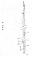
Fig. 2 is a sectional view for explaining a method of producing the all-solid-state secondary battery. -
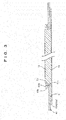
Fig. 3 is a sectional view for explaining a method of producing the all-solid-state secondary battery. -
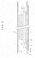
Fig. 4 is a sectional view for explaining a method of producing the all-solid-state secondary battery. -
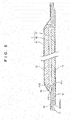
Fig. 5 is a sectional view for explaining a method of producing the all-solid-state secondary battery. -
Fig. 6 is a sectional view for explaining a method of producing the all-solid-state secondary battery. -
Fig. 7 is a sectional view for explaining a method of producing the all-solid-state secondary battery. -
Fig. 8 is a sectional view for explaining a method of producing the all-solid-state secondary battery. -
Fig. 9 is a graph showing charge-discharge curves of the all-solid-state secondary battery according to an example of the present invention. -
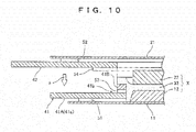
Fig. 10 is a sectional view of a main part of an all-solid-state secondary battery according to a variation of the present invention. - An all-solid-state secondary battery and a method of producing the same according to an embodiment of the present invention will be described below in accordance with the accompanying drawings.
- First, the configuration of the all-solid-state secondary battery will be described
- As shown in
Fig. 1 , the all-solid-statesecondary battery 1 includes a laminate X and a plate-shapedinsulating member 41 both arranged between a pair of collectors. The pair of collectors are constituted by apositive electrode collector 11 and anegative electrode collector 21. The laminate X includes apositive electrode layer 12, asolid electrolyte layer 32, and anegative electrode layer 22 stacked in this order. The plate-shapedinsulating member 41 is arranged around the laminate X and contacted at least with thesolid electrolyte layer 32 to electrically insulate thepositive electrode layer 12 and thenegative electrode layer 22 from each other. In the insulatingmember 41, a contactinner edge portion 41b contacted with the laminate X has a larger thickness than a plate-shaped portion 41a positioned on the outer side. Further, theinsulating member 41 is adhered to thepositive electrode collector 11 and thenegative electrode collector 21 via a loweradhesive layer 51 and an upperadhesive layer 52. - The lower
adhesive layer 51 and the upperadhesive layer 52 are positioned at predetermined distances (L1, L2) from an end surface of the contactinner edge portion 41b of theinsulating member 41 respectively. That is, the portion of thepositive electrode collector 11 corresponding to the predetermined length L1 is an unconstrained portion that is not constrained by other members, and the portion of thenegative electrode collector 21 corresponding to the predetermined length L2 is an unconstrained portion that is not constrained by other members. These unconstrained portions can be deformed freely. In other words, these unconstrained portions can absorb the distortion produced when an external force acts on thecollectors - The
insulating member 41 is constituted by an insulating sheet made of a polymer material such as a PET film. Theadhesive layers - Further, the
insulating member 41 disposed around the laminate X includes anopening portion 41c in which the laminate X is laminated (or guided), and the contactinner edge portion 41b contacted with the laminate X constitutes a peripheral portion of theopening portion 41c. The thickness of the contactinner edge portion 41b is larger (higher) than the total of thepositive electrode layer 12 and thesolid electrolyte layer 32, for example. - The
positive electrode layer 12 and thenegative electrode layer 22 are made of a powdery composite electrode material, and thesolid electrolyte layer 32 is also made of a powder material The composite electrode material is a mixture of an electrode active material and a solid electrolyte, but in some cases, the composite electrode material includes an electrode active material only. Accordingly, the laminate X will be referred to as "the powder layers" to emphasize that it is made of a powder material. - The shape and size of the all-solid-state
secondary battery 1 will now be described It appropriately has a square (circular or polygonal) shape in a plan view with the length of one side thereof ranging from 30 to 300 mm and a thickness thereof ranging from 50 to 500 µm. Accordingly, the laminate X has a square shape in a plan view, and theopening portion 41c for guiding thepositive electrode layer 12 and thesolid electrolyte layer 32 of the laminate X also has a square shape in a plan view. - In
Fig. 1 , the all-solid-state secondary battery rests on a horizontal plane, with its positive electrode side positioned low and its negative electrode side positioned high. Naturally, it is also possible that the negative electrode side is positioned low and the positive electrode side is positioned high. - The constituent materials of the main part of the all-solid-secondary battery will be described collectively after describing the production method
- The method of producing the all-solid-state secondary battery will be hereinafter described in detail with reference to
Figs. 2 to 8 . - As shown in
Fig. 2 , theinsulating member 41 is adhered onto the surface of thepositive electrode collector 11 via the loweradhesive layer 51. Theinsulating member 41 has anopening portion 41c that can guide thepositive electrode layer 12, and the contactinner edge portion 41b of theopening portion 41c has a larger thickness than the plate-shaped portion 41a on the outer side thereof. - It is herein supposed that the contact
inner edge portion 41b having a larger thickness is formed by adhering a tape-shapedsub-insulating member 41B having a predetermined width onto the top surface of an inner peripheral portion of a plate-shaped main insulatingmember 41A via anadhesive layer 53. - Next, as shown in
Fig. 3 , thepositive electrode layer 12 is arranged on the surface of thepositive electrode collector 11 within the openingportion 41c provided in the insulatingmember 41, or the main insulatingmember 41A. - Next, as shown in
Fig. 4 , thesolid electrolyte layer 32 having a predetermined thickness is provided on the top surface of thepositive electrode layer 12. The outer peripheral portion of thesolid electrolyte layer 32 is provided to cover the top surface of the tape-shapedsub-insulating member 41B having a width of 1 mm, for example. - Next, as shown in
Fig. 5 , thenegative electrode layer 22 having a predetermined thickness is provided on the top surface of thesolid electrolyte layer 32 to complete the laminate X. - Next, as shown in
Figs. 6 and7 , anegative electrode collector 21 with anupper adhesive layer 52 attached on a periphery thereof is provided on the top surface of thenegative electrode layer 22, and the work is subjected to temporary pressing with a low pressure of about 5,000 Pa while drawing the air away. Thenegative electrode collector 21 is adhered to the top surface of the insulatingmember 41 via theupper adhesive layer 52. - Next, as shown in
Fig. 8 , the work is subjected to full pressing with a high pressure of about 10 ton/cm2, while drawing the inside air away. - When the
negative electrode collector 21 is pressed from above, an elastic member such as a rubber plate is provided between thenegative electrode collector 21 and a pressing member (not shown). - Finally, the battery including the laminate X between the
collectors - Thus, a unitary all-solid-state secondary battery is obtained Typically, an all-solid-state secondary battery includes a plurality of unitary batteries stacked in series or arranged in parallel
- When the work is subjected to full pressing, wrinkles of the
collectors - The main part of the above production method can be described as including the following steps.
- This method is a method of producing an all-solid-state secondary battery, the all-solid-state secondary battery including: a pair of collectors; a laminate; and a plate-shaped insulating member, the laminate and the insulating member being arranged between the pair of collectors, the laminate including a positive electrode layer, a solid electrolyte layer, and a negative electrode layer stacked together, the insulating member being arranged around the laminate and contacted at least with the solid electrolyte layer to electrically insulate the positive electrode layer and the negative electrode layer from each other, the method comprising the steps of: adhering, to a surface of one of the pair of collectors, the plate-shaped insulating member including an opening portion capable of guiding the positive electrode layer or the negative electrode layer and including an inner edge portion of the opening portion having a larger thickness than an outer side thereof; arranging the positive electrode layer or the negative electrode layer in the opening portion of the insulating member adhered in the previous step; arranging the solid electrolyte layer on a top surface of the positive electrode layer or the negative electrode layer arranged in the previous step; arranging the negative electrode layer or the positive electrode layer on a top surface of the solid electrolyte layer arranged in the previous step, and obtaining a laminate; and arranging the other of the pair of collectors on the laminate obtained in the previous step and then applying a pressure.
- In the above embodiment, it was described that the contact inner edge portion of the insulating member contacted with the laminate has a larger thickness than the plate-shaped portion on the outer side. It is also possible to described that the contact inner edge portion of the insulating member contacted with the laminate has a larger thickness than the plate-shaped portion on the outer side, so as to provide a collapse preventing portion that can prevent the collapse of the peripheral portion of the laminate, and it is also possible to describe that the contact inner edge portion of the insulating member contacted with the laminate has a larger thickness than the plate-shaped portion on the outer side, so as to provide a shear collapse preventing portion that can prevent the shear collapse of the peripheral portion of the laminate when the battery is pressed
- The materials of the main components of the above all-solid-state
secondary battery 1 will be hereinafter described - The
positive electrode collector 11 and thenegative electrode collector 21 are constituted by a thin plate or a foil made of copper (Cu), magnesium (Mg), a stainless steel titanium (Ti), iron (Fe), cobalt (Co), nickel (Ni), zinc (Zn), aluminum (Al), germanium (Ge), indium (In), lithium (Li), tin (Sn), or an alloy of these metals. The thin plate or the foil has a thickness of 5 µm to 100 µm. In the embodiment, thepositive electrode collector 11 is constituted by an aluminum foil, and thenegative electrode collector 21 is constituted by a copper foil Further, the surfaces of thecollectors collectors positive electrode collector 11 is constituted by an aluminum foil subjected to an etching treatment (also referred to as an etched aluminum foil). Thenegative electrode collector 21 is constituted by a copper foil subjected to the etching treatment (also referred to as the roughened copper foil), but it is also possible that thenegative electrode collector 21 is constituted by a copper foil not subjected to the etching treatment. Further, the insulating member 41 (41A, 41B) is constituted by an insulating sheet made of a polymer material such as a PET film. - With such collectors subjected to the etching treatment, the cavities produced by etching are collapsed by the pressing in producing the all-solid-state secondary battery, such that the cavities tend to bite the surfaces of the electrode layers, that is, the
positive electrode layer 12 and thenegative electrode layer 22. Accordingly, the collectors and the electrode layers tend to be integrated together. - The electrode layers are made of a mixture material including, at a predetermined ratio, an electrode active material that ensures an electron conduction path between particles for transferring electrons and a solid electrolyte having ion conductivity. Since the solid electrolyte having lithium ion conductivity is thus mixed in the electron active material and provides ion conductivity in addition to the electron conductivity, an ion conduction path can be ensured between particles.
- The positive electrode active material suited for the
positive electrode layer 12 is any material that allows insertion and separation of lithium ions. Examples of the positive electrode active material include a layered oxide such as lithium-nickel composite oxide (LiNixM1-xO2 where M is at least one of Co, Al, Mn, V, Cr, Mg, Ca, Ti, Zr, Nb, Mo, and W), lithium cobaltate (LiCoO2), lithium nickelate (LiNiO2), and lithium manganate (LiMn2O4), a solid solution such as lithium iron phosphate (LiFePO4) having an olivine structure, lithium manganate (LiMn2O4, LizMnO3, LiMO2) having a spinel structure, or a mixture thereof, and sulfur (S) and a sulfide such as lithium sulfide (LizS). In the embodiment, the positive electrode active material is lithium-nickel-cobalt-aluminum composite oxide (LiNi0.8Co0.15Al0.05O2, hereinafter referred to as NCA-based composite oxide). - On the other hand, the negative electrode active material suited for the
negative electrode layer 22 is a carbon material such as natural graphite, artificial graphite, graphite carbon fiber, resin calcined carbon, or an alloy-based material to be combined with the solid electrolyte. Examples of the alloy-based material include lithium alloys (LiAl, LiZn, Li3Bi, Li3Cd, Li3Sb, Li4Si, Li4.4Pb, Li4.4Sn, Li0.17C, LiC6, etc.), lithium titanate (Li4Ti5O12), and metal oxides of Zn, etc. In the embodiment, the negative electrode active material is natural or artificial graphite. - Further, the positive electrode active material and the negative electrode active material may have coatings on the surfaces thereof, the coating being made of zirconia (ZrO2), alumina (Al2O3), lithium titanate (Li4Ti5O12], lithium niobate (Li4NbO3), carbon (C), etc.
- The solid electrolytes can be roughly divided into organic polymer electrolytes (also referred to as organic solid electrolytes) and inorganic solid electrolytes, and both can be used as the solid electrolyte. The inorganic solid electrolytes can be roughly divided into oxide materials and sulfide materials, and both can be used Further, the inorganic solid electrolyte can be appropriately selected from crystalline or amorphous ones. That is, the solid electrolyte can be appropriately selected from materials made of an organic compound, an inorganic compound, or a mixture thereof. More specifically, examples of the material that can be used as the solid electrolyte include lithium-containing metal oxides (containing one or more metals) such as Li2-SiO2 and Li2-SiO2-P2O5, lithium-containing metal nitride such as LixPyO1-zN2, lithium-containing sulfide glasses such as those based on Li2S-P2S5, Li2S-SiS2, Li2S-B2S3, Li2S-GeS2, Li2S-SiS2-LiI, Li2S-SiS2-Li3PO4, Li2S-Ge2S2, Li2S-GeS2-P2S5. and Li2S-GeS2-ZnS, and lithium-containing transition metal oxides such as PEO (polyethylene oxide), PVDF (polyvinylidene-fluoride), lithium phosphate (Li3PO4), and lithium-titanium oxide. In the embodiment, the solid electrolyte is a Li2S-P2S5-based glass among the sulfide inorganic solid electrolytes based on sulfide glasses having a high ion conductivity. The solid electrolyte suited for the
solid electrolyte layer 32 is either the same as or different from the solid electrolyte used in thepositive electrode layer 12 and thenegative electrode layer 22. - In the embodiment, the adhesive layers are constituted by pressure sensitive adhesives such as double-sided adhesive tapes for convenience of handling. It is also possible to use liquid or solid adhesives.
- According to the above all-solid-state secondary battery and the method of producing the same, the contact
inner edge portion 41b of the insulatingmember 41 contacted with the laminate X has a larger thickness than the plate-shapedportion 41a positioned on the outer side. Therefore, it is possible to prevent the collapse due to a shearing force occurring in the peripheral portion of the laminate X when the laminate X is pressed, and therefore it is possible to prevent the occurrence of an internal short circuit (electric short circuit). That is, the inner edge portion of theopening portion 41a of the insulatingmember 41 serves as a collapse preventing block that can prevent shear collapse occurring when the laminate X is pressed - For example, when the
positive electrode layer 12, thesolid electrolyte layer 32, and thenegative electrode layer 22 are simply stacked together, the middle portion is the thickest and the peripheral portion is thin. In this state, pressing with a high pressure does not cause a large force to be applied to the peripheral portion, and therefore, the powder materials are insufficiently fixed together in the peripheral portion, and the layer structure tends to be broken due to an impact or deformation of the collectors. Such a situation can be avoided - The results obtained when the all-solid-state secondary battery actually produced is charged and discharged will be hereinafter described
- In this all-solid-state secondary battery, the
positive electrode collector 11 was constituted by a roughened aluminum foil (etched aluminum) having a thickness of 20 µm, and thenegative electrode collector 21 was constituted by a copper foil having a thickness of 18 µm. The insulatingmember 41 was constituted by a PET film (polyethylene terephthalate film) having a thickness of 50 µm. Each of the loweradhesive layer 51 and theupper adhesive layer 52 was constituted by a pressure sensitive adhesives film (double-sided adhesive tape) having a thickness of 30 µm and a width of 2 mm, and theadhesive layer 53 of the contactinner edge portion 41b was constituted by the same having a width of 1 mm. - Further, the
positive electrode layer 12 was constituted by a mixture of the NCA-based composite oxide as the positive electrode active material and a glass ceramic composed of Li2S(80 mol%)-P2S5(20 mol%) as the solid electrolyte at a ratio of 7:3. Thenegative electrode layer 22 was constituted by a mixture of graphite powder as the negative electrode active material and a glass ceramic composed of Li2S(80 mol%)-P2S5(20 mol%) as the solid electrolyte at a ratio of 6:4. The solid electrolyte in thesolid electrolyte layer 32 was constituted by a glass ceramic composed of Li2S(80 mol%)-P2S5(20 mol%). - The components were formed by, for example, electrostatic screen method to the respective predetermined thicknesses such that, after the full pressing, the
positive electrode layer 12 has a thickness of about 70 µm, thenegative electrode layer 22 has a thickness of about 130 µm, and thesolid electrolyte layer 32 has a thickness of about 90 µm. - Finally, the obtained battery was sandwiched with a pair of stainless steel plates each having a square shape 70 mm on a side and having a thickness of 0.3 mm, and then sandwiched with laminated films having tab leads for extracting electricity, and the periphery of the laminated films was subjected to thermal fusion bonding under a vacuum to prepare the all-solid-state
secondary battery 1. - For example, nine pieces of the all-solid-state
secondary battery 1 were prepared, and all these batteries were successfully charged and discharged at 0.1 C and 4 to 2 V. Typical charge-discharge curves of these batteries are shown inFig. 9 . These charge-discharge curves show that this all-solid-state secondary battery operated normally. The pressing state of the all-solid-state secondary battery was checked with a pressure-sensitive paper, and it was found that the portion was pressed with a high pressure. - Five batteries not having the contact inner edge portion constituted by the insulating member were prepared as comparative examples. When these batteries were charged and discharged at 0.1 C and 4 to 2 V, internal short circuit occurred in four of the batteries. The other one battery, in which internal short circuit did not occur, was charged abnormally.
- In the above embodiment, the contact inner edge portion of the opening portion of the insulating member arranged around the laminate has a larger thickness. As shown in
Fig. 10 for example, it is also possible that an annular outer insulatingmember 42 that can be arranged along the outer side of the tape-shapedsub-insulating member 41B is adhered to thenegative electrode collector 21 side shown inFig. 7 via theupper adhesive layer 52, and when the battery is pressed (as shown by the arrow a), the outer insulatingmember 42 is adhered to the top surface of the plate-shapedportion 41A (41a) of the insulatingmember 41 via anadhesive layer 54. In another words, the total thickness of the insulatingmember 41 is enlarged to be above the lower surface of thesolid electrolyte layer 32 of the laminate X after pressing.
Claims (3)
- An all-solid-state secondary battery comprising: a pair of collectors; a laminate; and a plate-shaped insulating member, the laminate and the insulating member being arranged between the pair of collectors, the laminate including a positive electrode layer, a solid electrolyte layer, and a negative electrode layer stacked together, the insulating member being arranged around the laminate and contacted at least with the solid electrolyte layer to electrically insulate the positive electrode layer and the negative electrode layer from each other,
wherein in the insulating member, a contact inner edge portion contacted with the laminate has a larger thickness than a plate-shaped portion on an outer side. - The all-solid-state secondary battery of claim 1, wherein the insulating member is arranged between the pair of collectors via a positive electrode-side adhesive layer and a negative electrode-side adhesive layer, and each adhesive layer is arranged distant from an inner end of the insulating member so as to provide a distortion absorbing region to each of the collectors.
- A method of producing an all-solid-state secondary battery, the all-solid-state secondary battery including: a pair of collectors; a laminate; and a plate-shaped insulating member, the laminate and the insulating member being arranged between the pair of collectors, the laminate including a positive electrode layer, a solid electrolyte layer, and a negative electrode layer stacked together, the insulating member being arranged around the laminate and contacted at least with the solid electrolyte layer to electrically insulate the positive electrode layer and the negative electrode layer from each other, the method comprising the steps of:adhering, to a surface of one of the pair of collectors, the plate-shaped insulating member including an opening portion capable of guiding the positive electrode layer or the negative electrode layer and including an inner edge portion of the opening portion having a larger thickness than an outer side thereof;arranging the positive electrode layer or the negative electrode layer in the opening portion of the insulating member adhered in the previous step;arranging the solid electrolyte layer on a top surface of the positive electrode layer or the negative electrode layer arranged in the previous step;arranging the negative electrode layer or the positive electrode layer on a top surface of the solid electrolyte layer arranged in the previous step, and obtaining a laminate; andarranging the other of the pair of collectors on the laminate obtained in the previous step and then applying a pressure.
Applications Claiming Priority (2)
| Application Number | Priority Date | Filing Date | Title |
|---|---|---|---|
| JP2015125202A JP6608188B2 (en) | 2015-06-23 | 2015-06-23 | All-solid secondary battery and manufacturing method thereof |
| PCT/JP2016/063132 WO2016208271A1 (en) | 2015-06-23 | 2016-04-27 | All-solid-state secondary battery and production method therefor |
Publications (3)
| Publication Number | Publication Date |
|---|---|
| EP3316382A4 EP3316382A4 (en) | 2018-05-02 |
| EP3316382A1 true EP3316382A1 (en) | 2018-05-02 |
| EP3316382B1 EP3316382B1 (en) | 2019-10-02 |
Family
ID=57585518
Family Applications (1)
| Application Number | Title | Priority Date | Filing Date |
|---|---|---|---|
| EP16814042.4A Active EP3316382B1 (en) | 2015-06-23 | 2016-04-27 | All-solid-state secondary battery and production method therefor |
Country Status (6)
| Country | Link |
|---|---|
| US (1) | US10651506B2 (en) |
| EP (1) | EP3316382B1 (en) |
| JP (1) | JP6608188B2 (en) |
| KR (1) | KR102508379B1 (en) |
| CN (1) | CN107683543B (en) |
| WO (1) | WO2016208271A1 (en) |
Cited By (5)
| Publication number | Priority date | Publication date | Assignee | Title |
|---|---|---|---|---|
| EP3451435A4 (en) * | 2016-04-26 | 2019-11-20 | Hitachi Zosen Corporation | All-solid-state secondary battery |
| EP3557685A4 (en) * | 2016-12-16 | 2020-01-01 | Hitachi Zosen Corporation | All-solid state secondary cell and production method for same |
| EP3667801A1 (en) * | 2018-12-12 | 2020-06-17 | Panasonic Intellectual Property Management Co., Ltd. | All-solid-state battery |
| EP3823075A4 (en) * | 2018-07-13 | 2022-06-29 | Hitachi Zosen Corporation | Installation for manufacturing all-solid secondary battery |
| US12424655B2 (en) * | 2017-12-28 | 2025-09-23 | Kanadevia Corporation | All-solid-state battery, method for manufacturing same, and processing device |
Families Citing this family (19)
| Publication number | Priority date | Publication date | Assignee | Title |
|---|---|---|---|---|
| JP6726503B2 (en) * | 2016-03-31 | 2020-07-22 | 日立造船株式会社 | All-solid secondary battery and manufacturing method thereof |
| CN107305961B (en) * | 2016-04-25 | 2022-03-29 | 松下知识产权经营株式会社 | Battery, battery manufacturing method, and battery manufacturing apparatus |
| CN108933226B (en) * | 2017-05-23 | 2020-06-16 | 辉能科技股份有限公司 | Flexible battery structure |
| JP7157943B2 (en) | 2017-07-25 | 2022-10-21 | パナソニックIpマネジメント株式会社 | battery |
| JP6852713B2 (en) * | 2018-05-09 | 2021-03-31 | トヨタ自動車株式会社 | Laminated battery |
| WO2019226674A1 (en) * | 2018-05-21 | 2019-11-28 | University Of Utah Research Foundation | Composite solid electrolyte including lithium iron phosphate |
| JP7167488B2 (en) | 2018-05-29 | 2022-11-09 | トヨタ自動車株式会社 | Positive electrode, all-solid battery and manufacturing method thereof |
| JP2020061258A (en) * | 2018-10-09 | 2020-04-16 | 本田技研工業株式会社 | Manufacturing method of solid state battery |
| JP7178633B2 (en) | 2018-12-27 | 2022-11-28 | パナソニックIpマネジメント株式会社 | All-solid-state battery and manufacturing method thereof |
| US11056717B2 (en) | 2019-01-31 | 2021-07-06 | University Of Maryland, College Park | Lithium phosphate derivative compounds as Li super-ionic conductor, solid electrolyte and coating layer for lithium metal battery and lithium-ion battery |
| WO2020250981A1 (en) * | 2019-06-13 | 2020-12-17 | 株式会社村田製作所 | Solid-state battery |
| JP7150672B2 (en) * | 2019-07-19 | 2022-10-11 | 本田技研工業株式会社 | Secondary battery and manufacturing method thereof |
| JP7465077B2 (en) * | 2019-11-21 | 2024-04-10 | 太陽誘電株式会社 | All-solid-state battery and its manufacturing method |
| JP7101655B2 (en) * | 2019-12-16 | 2022-07-15 | 本田技研工業株式会社 | Battery pack |
| KR20220027499A (en) * | 2020-08-27 | 2022-03-08 | 삼성에스디아이 주식회사 | All Solid secondary battery |
| JP7826322B2 (en) * | 2021-08-12 | 2026-03-09 | Tdk株式会社 | all solid state battery |
| US11901564B2 (en) * | 2022-02-09 | 2024-02-13 | Socpra Sciences Et Génie S.E.C. | Anisotropic porous germanium nanostructures achieved with fast bipolar electrochemical etching and chemical etching |
| KR102457705B1 (en) * | 2022-07-21 | 2022-10-21 | 부산대학교 산학협력단 | All-solid-battery and manufacturing method thereof |
| JP7805895B2 (en) * | 2022-08-26 | 2026-01-26 | 本田技研工業株式会社 | Lithium metal secondary battery |
Family Cites Families (12)
| Publication number | Priority date | Publication date | Assignee | Title |
|---|---|---|---|---|
| JPH0451455A (en) * | 1990-06-18 | 1992-02-19 | Yuasa Corp | Thin form cell |
| JPH0547360A (en) * | 1991-08-09 | 1993-02-26 | Yuasa Corp | Thin battery |
| US5547780A (en) * | 1993-01-18 | 1996-08-20 | Yuasa Corporation | Battery precursor and a battery |
| JP5165843B2 (en) * | 2004-12-13 | 2013-03-21 | パナソニック株式会社 | Laminated body including active material layer and solid electrolyte layer, and all-solid lithium secondary battery using the same |
| JP5131283B2 (en) * | 2009-05-11 | 2013-01-30 | トヨタ自動車株式会社 | Solid battery manufacturing method and solid battery |
| JP5414371B2 (en) | 2009-06-04 | 2014-02-12 | 出光興産株式会社 | Manufacturing method of all-solid-state lithium ion secondary battery |
| WO2012124108A1 (en) * | 2011-03-17 | 2012-09-20 | トヨタ自動車株式会社 | Solid-state battery and solid-state battery manufacturing method |
| JP6066574B2 (en) | 2012-03-05 | 2017-01-25 | 日立造船株式会社 | Manufacturing method of all-solid-state secondary battery |
| JP2014102982A (en) * | 2012-11-20 | 2014-06-05 | Toyota Motor Corp | All-solid-state battery and manufacturing method for the same |
| JP5776722B2 (en) * | 2013-04-24 | 2015-09-09 | 日産自動車株式会社 | Nonaqueous electrolyte secondary battery |
| JP6095472B2 (en) * | 2013-05-13 | 2017-03-15 | 日立造船株式会社 | All-solid battery manufacturing method and all-solid battery manufacturing apparatus |
| JP6324296B2 (en) * | 2014-11-04 | 2018-05-16 | 日立造船株式会社 | All solid state secondary battery |
-
2015
- 2015-06-23 JP JP2015125202A patent/JP6608188B2/en active Active
-
2016
- 2016-04-27 KR KR1020177035873A patent/KR102508379B1/en active Active
- 2016-04-27 US US15/738,358 patent/US10651506B2/en active Active
- 2016-04-27 CN CN201680035240.2A patent/CN107683543B/en active Active
- 2016-04-27 WO PCT/JP2016/063132 patent/WO2016208271A1/en not_active Ceased
- 2016-04-27 EP EP16814042.4A patent/EP3316382B1/en active Active
Cited By (8)
| Publication number | Priority date | Publication date | Assignee | Title |
|---|---|---|---|---|
| EP3451435A4 (en) * | 2016-04-26 | 2019-11-20 | Hitachi Zosen Corporation | All-solid-state secondary battery |
| EP3557685A4 (en) * | 2016-12-16 | 2020-01-01 | Hitachi Zosen Corporation | All-solid state secondary cell and production method for same |
| US11784353B2 (en) | 2016-12-16 | 2023-10-10 | Hitachi Zosen Corporation | All-solid state secondary cell and production method for the same |
| US12424655B2 (en) * | 2017-12-28 | 2025-09-23 | Kanadevia Corporation | All-solid-state battery, method for manufacturing same, and processing device |
| EP3823075A4 (en) * | 2018-07-13 | 2022-06-29 | Hitachi Zosen Corporation | Installation for manufacturing all-solid secondary battery |
| EP3667801A1 (en) * | 2018-12-12 | 2020-06-17 | Panasonic Intellectual Property Management Co., Ltd. | All-solid-state battery |
| CN111313079A (en) * | 2018-12-12 | 2020-06-19 | 松下知识产权经营株式会社 | All-solid-state battery |
| US11476503B2 (en) | 2018-12-12 | 2022-10-18 | Panasonic Intellectual Property Management Co., Ltd. | All-solid-state battery |
Also Published As
| Publication number | Publication date |
|---|---|
| JP6608188B2 (en) | 2019-11-20 |
| EP3316382B1 (en) | 2019-10-02 |
| CN107683543A (en) | 2018-02-09 |
| CN107683543B (en) | 2020-03-27 |
| US10651506B2 (en) | 2020-05-12 |
| EP3316382A4 (en) | 2018-05-02 |
| KR102508379B1 (en) | 2023-03-08 |
| WO2016208271A1 (en) | 2016-12-29 |
| US20180198169A1 (en) | 2018-07-12 |
| JP2017010786A (en) | 2017-01-12 |
| KR20180020150A (en) | 2018-02-27 |
Similar Documents
| Publication | Publication Date | Title |
|---|---|---|
| EP3316382B1 (en) | All-solid-state secondary battery and production method therefor | |
| CN110073539B (en) | All-solid-state secondary battery and method for manufacturing same | |
| US10686213B2 (en) | Battery | |
| EP2966721B1 (en) | Non-aqueous electrolyte secondary battery | |
| JP6576072B2 (en) | Manufacturing method of all-solid-state secondary battery | |
| EP3125351B1 (en) | All-solid-state secondary battery | |
| JP6726503B2 (en) | All-solid secondary battery and manufacturing method thereof | |
| US12424655B2 (en) | All-solid-state battery, method for manufacturing same, and processing device | |
| JP6324296B2 (en) | All solid state secondary battery | |
| KR20190002492A (en) | All solid secondary batteries | |
| EP3561938B1 (en) | Method and apparatus for producing all-solid-state battery | |
| US20230327129A1 (en) | Battery and method for producing battery | |
| KR20220122522A (en) | All-solid-state lithium battery |
Legal Events
| Date | Code | Title | Description |
|---|---|---|---|
| STAA | Information on the status of an ep patent application or granted ep patent |
Free format text: STATUS: THE INTERNATIONAL PUBLICATION HAS BEEN MADE |
|
| PUAI | Public reference made under article 153(3) epc to a published international application that has entered the european phase |
Free format text: ORIGINAL CODE: 0009012 |
|
| STAA | Information on the status of an ep patent application or granted ep patent |
Free format text: STATUS: REQUEST FOR EXAMINATION WAS MADE |
|
| 17P | Request for examination filed |
Effective date: 20171207 |
|
| A4 | Supplementary search report drawn up and despatched |
Effective date: 20180316 |
|
| AK | Designated contracting states |
Kind code of ref document: A1 Designated state(s): AL AT BE BG CH CY CZ DE DK EE ES FI FR GB GR HR HU IE IS IT LI LT LU LV MC MK MT NL NO PL PT RO RS SE SI SK SM TR |
|
| AX | Request for extension of the european patent |
Extension state: BA ME |
|
| DAV | Request for validation of the european patent (deleted) | ||
| DAX | Request for extension of the european patent (deleted) | ||
| STAA | Information on the status of an ep patent application or granted ep patent |
Free format text: STATUS: EXAMINATION IS IN PROGRESS |
|
| 17Q | First examination report despatched |
Effective date: 20181107 |
|
| GRAP | Despatch of communication of intention to grant a patent |
Free format text: ORIGINAL CODE: EPIDOSNIGR1 |
|
| STAA | Information on the status of an ep patent application or granted ep patent |
Free format text: STATUS: GRANT OF PATENT IS INTENDED |
|
| INTG | Intention to grant announced |
Effective date: 20190503 |
|
| RIN1 | Information on inventor provided before grant (corrected) |
Inventor name: RYOU SHIKEN Inventor name: FUKUI HIDEYUKI Inventor name: TAKANO YASUSHI |
|
| GRAS | Grant fee paid |
Free format text: ORIGINAL CODE: EPIDOSNIGR3 |
|
| GRAA | (expected) grant |
Free format text: ORIGINAL CODE: 0009210 |
|
| STAA | Information on the status of an ep patent application or granted ep patent |
Free format text: STATUS: THE PATENT HAS BEEN GRANTED |
|
| AK | Designated contracting states |
Kind code of ref document: B1 Designated state(s): AL AT BE BG CH CY CZ DE DK EE ES FI FR GB GR HR HU IE IS IT LI LT LU LV MC MK MT NL NO PL PT RO RS SE SI SK SM TR |
|
| REG | Reference to a national code |
Ref country code: GB Ref legal event code: FG4D |
|
| REG | Reference to a national code |
Ref country code: CH Ref legal event code: EP Ref country code: AT Ref legal event code: REF Ref document number: 1187221 Country of ref document: AT Kind code of ref document: T Effective date: 20191015 |
|
| REG | Reference to a national code |
Ref country code: DE Ref legal event code: R096 Ref document number: 602016021843 Country of ref document: DE |
|
| REG | Reference to a national code |
Ref country code: IE Ref legal event code: FG4D |
|
| REG | Reference to a national code |
Ref country code: SE Ref legal event code: TRGR |
|
| REG | Reference to a national code |
Ref country code: NL Ref legal event code: FP |
|
| REG | Reference to a national code |
Ref country code: LT Ref legal event code: MG4D |
|
| REG | Reference to a national code |
Ref country code: AT Ref legal event code: MK05 Ref document number: 1187221 Country of ref document: AT Kind code of ref document: T Effective date: 20191002 |
|
| PG25 | Lapsed in a contracting state [announced via postgrant information from national office to epo] |
Ref country code: PL Free format text: LAPSE BECAUSE OF FAILURE TO SUBMIT A TRANSLATION OF THE DESCRIPTION OR TO PAY THE FEE WITHIN THE PRESCRIBED TIME-LIMIT Effective date: 20191002 Ref country code: LT Free format text: LAPSE BECAUSE OF FAILURE TO SUBMIT A TRANSLATION OF THE DESCRIPTION OR TO PAY THE FEE WITHIN THE PRESCRIBED TIME-LIMIT Effective date: 20191002 Ref country code: AT Free format text: LAPSE BECAUSE OF FAILURE TO SUBMIT A TRANSLATION OF THE DESCRIPTION OR TO PAY THE FEE WITHIN THE PRESCRIBED TIME-LIMIT Effective date: 20191002 Ref country code: GR Free format text: LAPSE BECAUSE OF FAILURE TO SUBMIT A TRANSLATION OF THE DESCRIPTION OR TO PAY THE FEE WITHIN THE PRESCRIBED TIME-LIMIT Effective date: 20200103 Ref country code: NO Free format text: LAPSE BECAUSE OF FAILURE TO SUBMIT A TRANSLATION OF THE DESCRIPTION OR TO PAY THE FEE WITHIN THE PRESCRIBED TIME-LIMIT Effective date: 20200102 Ref country code: PT Free format text: LAPSE BECAUSE OF FAILURE TO SUBMIT A TRANSLATION OF THE DESCRIPTION OR TO PAY THE FEE WITHIN THE PRESCRIBED TIME-LIMIT Effective date: 20200203 Ref country code: LV Free format text: LAPSE BECAUSE OF FAILURE TO SUBMIT A TRANSLATION OF THE DESCRIPTION OR TO PAY THE FEE WITHIN THE PRESCRIBED TIME-LIMIT Effective date: 20191002 Ref country code: FI Free format text: LAPSE BECAUSE OF FAILURE TO SUBMIT A TRANSLATION OF THE DESCRIPTION OR TO PAY THE FEE WITHIN THE PRESCRIBED TIME-LIMIT Effective date: 20191002 Ref country code: BG Free format text: LAPSE BECAUSE OF FAILURE TO SUBMIT A TRANSLATION OF THE DESCRIPTION OR TO PAY THE FEE WITHIN THE PRESCRIBED TIME-LIMIT Effective date: 20200102 Ref country code: ES Free format text: LAPSE BECAUSE OF FAILURE TO SUBMIT A TRANSLATION OF THE DESCRIPTION OR TO PAY THE FEE WITHIN THE PRESCRIBED TIME-LIMIT Effective date: 20191002 |
|
| PG25 | Lapsed in a contracting state [announced via postgrant information from national office to epo] |
Ref country code: IS Free format text: LAPSE BECAUSE OF FAILURE TO SUBMIT A TRANSLATION OF THE DESCRIPTION OR TO PAY THE FEE WITHIN THE PRESCRIBED TIME-LIMIT Effective date: 20200224 Ref country code: CZ Free format text: LAPSE BECAUSE OF FAILURE TO SUBMIT A TRANSLATION OF THE DESCRIPTION OR TO PAY THE FEE WITHIN THE PRESCRIBED TIME-LIMIT Effective date: 20191002 Ref country code: HR Free format text: LAPSE BECAUSE OF FAILURE TO SUBMIT A TRANSLATION OF THE DESCRIPTION OR TO PAY THE FEE WITHIN THE PRESCRIBED TIME-LIMIT Effective date: 20191002 Ref country code: RS Free format text: LAPSE BECAUSE OF FAILURE TO SUBMIT A TRANSLATION OF THE DESCRIPTION OR TO PAY THE FEE WITHIN THE PRESCRIBED TIME-LIMIT Effective date: 20191002 |
|
| PG25 | Lapsed in a contracting state [announced via postgrant information from national office to epo] |
Ref country code: AL Free format text: LAPSE BECAUSE OF FAILURE TO SUBMIT A TRANSLATION OF THE DESCRIPTION OR TO PAY THE FEE WITHIN THE PRESCRIBED TIME-LIMIT Effective date: 20191002 |
|
| REG | Reference to a national code |
Ref country code: DE Ref legal event code: R097 Ref document number: 602016021843 Country of ref document: DE |
|
| PG2D | Information on lapse in contracting state deleted |
Ref country code: IS |
|
| PG25 | Lapsed in a contracting state [announced via postgrant information from national office to epo] |
Ref country code: RO Free format text: LAPSE BECAUSE OF FAILURE TO SUBMIT A TRANSLATION OF THE DESCRIPTION OR TO PAY THE FEE WITHIN THE PRESCRIBED TIME-LIMIT Effective date: 20191002 Ref country code: EE Free format text: LAPSE BECAUSE OF FAILURE TO SUBMIT A TRANSLATION OF THE DESCRIPTION OR TO PAY THE FEE WITHIN THE PRESCRIBED TIME-LIMIT Effective date: 20191002 Ref country code: DK Free format text: LAPSE BECAUSE OF FAILURE TO SUBMIT A TRANSLATION OF THE DESCRIPTION OR TO PAY THE FEE WITHIN THE PRESCRIBED TIME-LIMIT Effective date: 20191002 Ref country code: IS Free format text: LAPSE BECAUSE OF FAILURE TO SUBMIT A TRANSLATION OF THE DESCRIPTION OR TO PAY THE FEE WITHIN THE PRESCRIBED TIME-LIMIT Effective date: 20200202 |
|
| PLBE | No opposition filed within time limit |
Free format text: ORIGINAL CODE: 0009261 |
|
| STAA | Information on the status of an ep patent application or granted ep patent |
Free format text: STATUS: NO OPPOSITION FILED WITHIN TIME LIMIT |
|
| PG25 | Lapsed in a contracting state [announced via postgrant information from national office to epo] |
Ref country code: IT Free format text: LAPSE BECAUSE OF FAILURE TO SUBMIT A TRANSLATION OF THE DESCRIPTION OR TO PAY THE FEE WITHIN THE PRESCRIBED TIME-LIMIT Effective date: 20191002 Ref country code: SM Free format text: LAPSE BECAUSE OF FAILURE TO SUBMIT A TRANSLATION OF THE DESCRIPTION OR TO PAY THE FEE WITHIN THE PRESCRIBED TIME-LIMIT Effective date: 20191002 Ref country code: SK Free format text: LAPSE BECAUSE OF FAILURE TO SUBMIT A TRANSLATION OF THE DESCRIPTION OR TO PAY THE FEE WITHIN THE PRESCRIBED TIME-LIMIT Effective date: 20191002 |
|
| 26N | No opposition filed |
Effective date: 20200703 |
|
| PG25 | Lapsed in a contracting state [announced via postgrant information from national office to epo] |
Ref country code: MC Free format text: LAPSE BECAUSE OF FAILURE TO SUBMIT A TRANSLATION OF THE DESCRIPTION OR TO PAY THE FEE WITHIN THE PRESCRIBED TIME-LIMIT Effective date: 20191002 Ref country code: SI Free format text: LAPSE BECAUSE OF FAILURE TO SUBMIT A TRANSLATION OF THE DESCRIPTION OR TO PAY THE FEE WITHIN THE PRESCRIBED TIME-LIMIT Effective date: 20191002 |
|
| REG | Reference to a national code |
Ref country code: CH Ref legal event code: PL |
|
| PG25 | Lapsed in a contracting state [announced via postgrant information from national office to epo] |
Ref country code: CH Free format text: LAPSE BECAUSE OF NON-PAYMENT OF DUE FEES Effective date: 20200430 Ref country code: LI Free format text: LAPSE BECAUSE OF NON-PAYMENT OF DUE FEES Effective date: 20200430 Ref country code: LU Free format text: LAPSE BECAUSE OF NON-PAYMENT OF DUE FEES Effective date: 20200427 |
|
| REG | Reference to a national code |
Ref country code: BE Ref legal event code: MM Effective date: 20200430 |
|
| PG25 | Lapsed in a contracting state [announced via postgrant information from national office to epo] |
Ref country code: BE Free format text: LAPSE BECAUSE OF NON-PAYMENT OF DUE FEES Effective date: 20200430 |
|
| PG25 | Lapsed in a contracting state [announced via postgrant information from national office to epo] |
Ref country code: IE Free format text: LAPSE BECAUSE OF NON-PAYMENT OF DUE FEES Effective date: 20200427 |
|
| PG25 | Lapsed in a contracting state [announced via postgrant information from national office to epo] |
Ref country code: TR Free format text: LAPSE BECAUSE OF FAILURE TO SUBMIT A TRANSLATION OF THE DESCRIPTION OR TO PAY THE FEE WITHIN THE PRESCRIBED TIME-LIMIT Effective date: 20191002 Ref country code: MT Free format text: LAPSE BECAUSE OF FAILURE TO SUBMIT A TRANSLATION OF THE DESCRIPTION OR TO PAY THE FEE WITHIN THE PRESCRIBED TIME-LIMIT Effective date: 20191002 Ref country code: CY Free format text: LAPSE BECAUSE OF FAILURE TO SUBMIT A TRANSLATION OF THE DESCRIPTION OR TO PAY THE FEE WITHIN THE PRESCRIBED TIME-LIMIT Effective date: 20191002 |
|
| PG25 | Lapsed in a contracting state [announced via postgrant information from national office to epo] |
Ref country code: MK Free format text: LAPSE BECAUSE OF FAILURE TO SUBMIT A TRANSLATION OF THE DESCRIPTION OR TO PAY THE FEE WITHIN THE PRESCRIBED TIME-LIMIT Effective date: 20191002 |
|
| PGFP | Annual fee paid to national office [announced via postgrant information from national office to epo] |
Ref country code: SE Payment date: 20230310 Year of fee payment: 8 |
|
| P01 | Opt-out of the competence of the unified patent court (upc) registered |
Effective date: 20230509 |
|
| PGFP | Annual fee paid to national office [announced via postgrant information from national office to epo] |
Ref country code: NL Payment date: 20230314 Year of fee payment: 8 |
|
| REG | Reference to a national code |
Ref country code: SE Ref legal event code: EUG |
|
| REG | Reference to a national code |
Ref country code: NL Ref legal event code: MM Effective date: 20240501 |
|
| PG25 | Lapsed in a contracting state [announced via postgrant information from national office to epo] |
Ref country code: NL Free format text: LAPSE BECAUSE OF NON-PAYMENT OF DUE FEES Effective date: 20240501 |
|
| PG25 | Lapsed in a contracting state [announced via postgrant information from national office to epo] |
Ref country code: NL Free format text: LAPSE BECAUSE OF NON-PAYMENT OF DUE FEES Effective date: 20240501 |
|
| PGFP | Annual fee paid to national office [announced via postgrant information from national office to epo] |
Ref country code: DE Payment date: 20250305 Year of fee payment: 10 |
|
| PG25 | Lapsed in a contracting state [announced via postgrant information from national office to epo] |
Ref country code: SE Free format text: LAPSE BECAUSE OF NON-PAYMENT OF DUE FEES Effective date: 20240428 |
|
| PGFP | Annual fee paid to national office [announced via postgrant information from national office to epo] |
Ref country code: GB Payment date: 20260313 Year of fee payment: 11 |
|
| REG | Reference to a national code |
Ref country code: DE Ref legal event code: R081 Ref document number: 602016021843 Country of ref document: DE Owner name: KANADEVIA CORPORATION, JP Free format text: FORMER OWNER: HITACHI ZOSEN CORPORATION, OSAKA-SHI, JP |
|
| PGFP | Annual fee paid to national office [announced via postgrant information from national office to epo] |
Ref country code: FR Payment date: 20260309 Year of fee payment: 11 |