EP3316063A1 - Travel route generating device - Google Patents
Travel route generating device Download PDFInfo
- Publication number
- EP3316063A1 EP3316063A1 EP17001726.3A EP17001726A EP3316063A1 EP 3316063 A1 EP3316063 A1 EP 3316063A1 EP 17001726 A EP17001726 A EP 17001726A EP 3316063 A1 EP3316063 A1 EP 3316063A1
- Authority
- EP
- European Patent Office
- Prior art keywords
- travel
- cell
- route
- work
- given
- Prior art date
- Legal status (The legal status is an assumption and is not a legal conclusion. Google has not performed a legal analysis and makes no representation as to the accuracy of the status listed.)
- Granted
Links
Images



Classifications
-
- G—PHYSICS
- G05—CONTROLLING; REGULATING
- G05D—SYSTEMS FOR CONTROLLING OR REGULATING NON-ELECTRIC VARIABLES
- G05D1/00—Control of position, course, altitude or attitude of land, water, air or space vehicles, e.g. using automatic pilots
- G05D1/02—Control of position or course in two dimensions
- G05D1/021—Control of position or course in two dimensions specially adapted to land vehicles
- G05D1/0268—Control of position or course in two dimensions specially adapted to land vehicles using internal positioning means
- G05D1/0274—Control of position or course in two dimensions specially adapted to land vehicles using internal positioning means using mapping information stored in a memory device
-
- G—PHYSICS
- G05—CONTROLLING; REGULATING
- G05D—SYSTEMS FOR CONTROLLING OR REGULATING NON-ELECTRIC VARIABLES
- G05D1/00—Control of position, course, altitude or attitude of land, water, air or space vehicles, e.g. using automatic pilots
- G05D1/02—Control of position or course in two dimensions
- G05D1/021—Control of position or course in two dimensions specially adapted to land vehicles
- G05D1/0212—Control of position or course in two dimensions specially adapted to land vehicles with means for defining a desired trajectory
- G05D1/0219—Control of position or course in two dimensions specially adapted to land vehicles with means for defining a desired trajectory ensuring the processing of the whole working surface
-
- G—PHYSICS
- G01—MEASURING; TESTING
- G01C—MEASURING DISTANCES, LEVELS OR BEARINGS; SURVEYING; NAVIGATION; GYROSCOPIC INSTRUMENTS; PHOTOGRAMMETRY OR VIDEOGRAMMETRY
- G01C21/00—Navigation; Navigational instruments not provided for in groups G01C1/00 - G01C19/00
- G01C21/20—Instruments for performing navigational calculations
-
- A—HUMAN NECESSITIES
- A01—AGRICULTURE; FORESTRY; ANIMAL HUSBANDRY; HUNTING; TRAPPING; FISHING
- A01B—SOIL WORKING IN AGRICULTURE OR FORESTRY; PARTS, DETAILS, OR ACCESSORIES OF AGRICULTURAL MACHINES OR IMPLEMENTS, IN GENERAL
- A01B69/00—Steering of agricultural machines or implements; Guiding agricultural machines or implements on a desired track
- A01B69/007—Steering or guiding of agricultural vehicles, e.g. steering of the tractor to keep the plough in the furrow
- A01B69/008—Steering or guiding of agricultural vehicles, e.g. steering of the tractor to keep the plough in the furrow automatic
-
- G—PHYSICS
- G01—MEASURING; TESTING
- G01C—MEASURING DISTANCES, LEVELS OR BEARINGS; SURVEYING; NAVIGATION; GYROSCOPIC INSTRUMENTS; PHOTOGRAMMETRY OR VIDEOGRAMMETRY
- G01C21/00—Navigation; Navigational instruments not provided for in groups G01C1/00 - G01C19/00
- G01C21/26—Navigation; Navigational instruments not provided for in groups G01C1/00 - G01C19/00 specially adapted for navigation in a road network
- G01C21/34—Route searching; Route guidance
-
- G—PHYSICS
- G05—CONTROLLING; REGULATING
- G05D—SYSTEMS FOR CONTROLLING OR REGULATING NON-ELECTRIC VARIABLES
- G05D1/00—Control of position, course, altitude or attitude of land, water, air or space vehicles, e.g. using automatic pilots
- G05D1/02—Control of position or course in two dimensions
- G05D1/021—Control of position or course in two dimensions specially adapted to land vehicles
- G05D1/0212—Control of position or course in two dimensions specially adapted to land vehicles with means for defining a desired trajectory
- G05D1/0214—Control of position or course in two dimensions specially adapted to land vehicles with means for defining a desired trajectory in accordance with safety or protection criteria, e.g. avoiding hazardous areas
-
- G—PHYSICS
- G05—CONTROLLING; REGULATING
- G05D—SYSTEMS FOR CONTROLLING OR REGULATING NON-ELECTRIC VARIABLES
- G05D1/00—Control of position, course, altitude or attitude of land, water, air or space vehicles, e.g. using automatic pilots
- G05D1/02—Control of position or course in two dimensions
- G05D1/021—Control of position or course in two dimensions specially adapted to land vehicles
- G05D1/0212—Control of position or course in two dimensions specially adapted to land vehicles with means for defining a desired trajectory
- G05D1/0217—Control of position or course in two dimensions specially adapted to land vehicles with means for defining a desired trajectory in accordance with energy consumption, time reduction or distance reduction criteria
-
- G—PHYSICS
- G05—CONTROLLING; REGULATING
- G05D—SYSTEMS FOR CONTROLLING OR REGULATING NON-ELECTRIC VARIABLES
- G05D1/00—Control of position, course, altitude or attitude of land, water, air or space vehicles, e.g. using automatic pilots
- G05D1/02—Control of position or course in two dimensions
- G05D1/021—Control of position or course in two dimensions specially adapted to land vehicles
- G05D1/0276—Control of position or course in two dimensions specially adapted to land vehicles using signals provided by a source external to the vehicle
- G05D1/0278—Control of position or course in two dimensions specially adapted to land vehicles using signals provided by a source external to the vehicle using satellite positioning signals, e.g. GPS
Definitions
- the present invention relates to a travel route generating device configured to generate a travel route for a work vehicle that works while traveling in a work field.
- JP 2008-67617 A discloses an agricultural work vehicle configured to generate a straight teaching route connecting a start point as a vehicle position upon teaching start and an end point as a vehicle position upon teaching end, and generate N straight travel routes distant by a work width and parallel to the straight teaching route.
- the agricultural work vehicle generates only the plurality of straight travel routes parallel to the straight teaching route.
- the agricultural work vehicle cannot generate any travel route if the agricultural work vehicle does not execute teaching travel in an actual field.
- the generated travel routes include no turn travel route for redirection in an outer peripheral area of the work field. This travel route generation technique is thus applicable only under highly limited conditions.
- US 6,728,607 B1 discloses a travel route generation system configured to generate a travel route achieving minimized energy consumption. This system initially estimates levels of energy necessary for passing cells obtained by mesh-dividing a work field in accordance with altitudes of the cells, and allocates, to the cells, numerical values indicating the estimated energy levels. The system subsequently applies the cells to a plurality of planned travel routes for a work vehicle in the work field, compares sums of the necessary energy levels for travel along the planned travel routes, and adopts the travel route having the lowest sum of the energy levels as an actual travel route. The travel route generation system is configured to compare the different travel routes by calculating the sums of the energy levels for the travel along the planned travel routes. The system is, however, not configured to plan the travel routes themselves. US 6,728,607 B1 merely suggests two types of travel routes including a plurality of parallel straight routes extending in the east-west direction or in the south-north direction and U-turn routes each connecting the straight routes adjacent to each other.
- a travel route generating device configured to generate a travel route for a work vehicle that works while traveling in a work field.
- the travel route generating device includes: a cell manager configured to manage a plurality of cells obtained by generating meshes in a topographical map of the work field at a predetermined interval; a travel weighting allocator configured to allocate to one of the cells, as weights given to travels, a weight given to left-turn travel, a weight given to straight travel, and a weight given to right-turn travel, the weights each indicating a travel effect degree in each cell passing direction upon travel from the cell to one of cells adjacent thereto; a cell passing route determiner configured to determine a cell passing route of passing the cell in accordance with the weight given to the left-turn travel, the weight given to the straight travel, and the weight given to the right-turn travel allocated to the cell; a weighting changer configured to change the weights given to travels which are allocated to a cell influenced by passage of the cell; and a
- the "plurality of cells obtained by generating meshes in a topographical map of the work field at a predetermined interval” may be a large number of cells.
- the "large number of cells” may be understood as indicating a number of cells that represent the work field with sufficient granularity to generate the travel route.
- the weights may be allocated in accordance with manners of passing the cells obtained by mesh generation (e.g. passing by left turn, by straight travel, and by right turn etc.). Left turn, straight travel, and right turn in each of the cells may differ from one another dependently on a position of entry to the cell.
- the weights of the cell may be allocated in each direction of entry to the cell. Exemplarily assume that an entry direction from the west to the east is called a first entry direction, an entry direction from the east to the west is called a second entry direction, an entry direction from the north to the south is called a third entry direction, and an entry direction from the south to the north is called a fourth entry direction.
- a weight given to left turn, a weight given to straight travel, and a weight given to right turn may be allocated in each of the four entry directions, so that at most twelve weights can be allocated to each of the cells.
- the cell passing route determiner may sequentially evaluate the weights allocated to each entered cell, and determine a passing route (e.g. left turn, straight travel, or right turn) of the cell.
- the cell passing routes sequentially determined by the cell passing route determiner may be connected to generate a target travel route for the work vehicle traveling in the work field.
- a desired travel route may be generated by preliminarily setting weights given to travels which define the desired travel route.
- the work vehicle may travel along the targeted work route in a manned or unmanned state.
- the travel route generating device may generate a desired travel route if a travel route planner preliminarily sets weights given to travels which are appropriate for the cells obtained by mesh generation as reference information indicating how the work vehicle should pass the work field (e.g. straight routes elongated in the east-west direction or in the south-north direction, and a spiral route mainly including turn travel route etc.).
- a travel route planner preliminarily sets weights given to travels which are appropriate for the cells obtained by mesh generation as reference information indicating how the work vehicle should pass the work field (e.g. straight routes elongated in the east-west direction or in the south-north direction, and a spiral route mainly including turn travel route etc.).
- the travel route generating device may facilitate generation of a travel route that is appropriate for each work field. This may lead to improving efficiency of the work to be performed by the work vehicle in the work field.
- the work vehicle may need to travel all over the work field depending on a type of work. It may be important to minimize unpassed cells upon generation of a travel route for the work vehicle.
- the cell manager may be further configured to execute backtracking when the route reaches a dead end with the cells including an unpassed cell.
- the cell manager may designate again a cell passed before entry to the dead-end cell, and sets to select a route other than the cell passing route determined last time as a route passing the cell.
- the backtracking may be executed until a new passable cell is found.
- the backtracking may contribute to covering as much area as possible within the work field by the generated travel route.
- the periphery of the work field may be bordered with a fence, a ridge, or the like, to prohibit travel to outside the work field. It may also be prohibited from approaching any obstacle like a rock, a tree, or a utility pole in the work field. Such travel prohibition can be achieved by not selecting a cell passing route including entry to a cell within a travel prohibited area, for example, setting the weight of such a cell passing route to "zero" (e.g. selection prohibited).
- the weights given to travels allocated by the travel weighting allocator may include weights given to prohibition of travel out of the work field and travel to an obstacle located in the work field. This may enable generation of a travel route that stays within the work field and that avoids the obstacle, which may lead to efficient work performed by the work vehicle.
- An agricultural work vehicle typically travels in a field as a work field efficiently by repeating straight travel as long as possible. Such travel can be achieved by allocating, to the cells not in a peripheral area, higher weights for straight travel than those for left turn and right turn.
- the weights given to travels allocated by the travel weighting allocator may include a weight prioritizing the straight travel. This may further contribute to improving efficiency of the work to be performed by the work vehicle.
- the weighting changer may be further configured to change the weights given to travels for prohibition of cell passing travel including entry to an already passed cell.
- the weighting changer may prohibit a cell passing route including entry to an already passed cell while allocating, to the cell passing route, a much lower weight than those of other cell passing routes. This may further contribute to improving efficiency of the work to be performed by the work vehicle.
- Determination of a cell passing route at the entered cell in the travel of the work vehicle may be dependent on the cell passing route at the previously passed cell or at the further previously passed cell.
- the weight at the entered cell may be favorably changed in accordance with a travel locus just before the entry, to prioritize such turn travel.
- the weighting changer may further be configured to change the weights given to travels which are allocated to the cell in accordance with a travel locus involving a plurality of cells continuously passed to reach the cell. This may further facilitate efficient generation of a travel route that is appropriate for the work field.
- the work vehicle In some circumstances, certain work travel requires the work vehicle to cover the front of the work field with a work width of a mounted work device.
- the interval at which the meshes are generated may be set to a work width of the work vehicle or a work width obtained from the work width of the work vehicle in consideration of a predetermined overlapping amount. The work vehicle can thus work in all over the work field by generating the travel route including travel to all the cells and traveling along the travel route.
- a certain work field has an entrance and an exit restricted for the work vehicle.
- the work vehicle may need to generate a travel route having a start point at a cell corresponding to the entrance and an end point at a cell corresponding to the exit.
- the travel route may have a start point cell and an end point cell corresponding to an entrance-exit port of the work field. This may enable generation of a travel route with starting and end points corresponding to the entrance and the exit of the work field.
- a computer-implemented method for generating a travel route for a work vehicle that works while traveling in a work field.
- the method may comprise:
- the computer program product may comprise computer-readable instructions that, when loaded and run on a computer, cause the computer to perform the method according to the above-stated aspect.
- the subject matter described in the application can be implemented as a method or as a system, possibly in the form of one or more computer program products.
- the subject matter described in the application can be implemented in a data signal or on a machine readable medium, where the medium is embodied in one or more information carriers, such as a CD-ROM, a DVD-ROM, a semiconductor memory, or a hard disk.
- Such computer program products may cause a data processing apparatus to perform one or more operations described in the application.
- subject matter described in the application can also be implemented as a system including a processor, and a memory coupled to the processor.
- the memory may encode one or more programs to cause the processor to perform one or more of the methods described in the application. Further subject matter described in the application can be implemented using various machines.
- Fig. 1 is a configuration diagram of an exemplary travel route generating device configured to generate a travel route for a work vehicle that works while traveling in a work field.
- the exemplary travel route generating device may initially divide a work field with meshes into a large number of cells.
- the travel route generating device may allocate a weight given to each cell passing route of passing the divided cells, e.g., each of a left-turn route, a straight travel route, and a right-turn route, and sequentially determine cell passing routes of passing the cells in accordance with the weights.
- the travel route generating device may generate a travel route for the work vehicle by sequentially connecting the determined cell passing routes.
- the initially allocated weights may be changed if the determined cell passing routes influence the weights.
- the travel route generating device may thus include basic functional units of a cell manager 61, a travel weighting allocator 62, a cell passing route determiner 63, a weighting changer 64, and a travel route generator 65.
- the travel route generating device may be substantially configured by a computer system configured to execute computer simulation.
- Each of the functional units may execute a program to achieve a specific function, and can alternatively be structured at least partially by hardware.
- Fig. 1 exemplifies the travel route generating device including, as a data input unit, a work field data input unit 67 configured to receive, from outside, topographical map data including an outline of the work field.
- the travel route generating device may include a mesh divider 66 configured to approximate the outline of the work field provided from the work field data input unit 67 to a circumscribing rectangle, and mesh-divide the circumscribing rectangle by a side length (e.g. a predetermined interval) obtained from a work width of the work vehicle in consideration of overlap.
- the work field may have outer end cells treated as special cells prohibiting passage to outside the work field.
- the cell manager 61 may manage cell passing simulation of sequentially passing a large number of cells obtained by mesh generation.
- the cell manager 61 may command allocation of weights to the cells so as to prioritize the travel pattern. If the attribute information includes positional information on an obstacle disturbing travel, the cell manager 61 may command allocation of weights to the cells so as to prohibit travel to the obstacle.
- the cell manager 61 may designate a start point cell as a start point of the travel route.
- the travel weighting allocator 62 may allocate, to each of the cells, weights, e.g., a weight given to left-turn travel, a weight given to straight travel, and a weight given to right-turn travel, indicative of travel effect degrees in respective cell passing directions upon travel from a cell to one of the cells adjacent thereto, in accordance with the command from the cell manager 61.
- weights can be indicated by numerical values or symbols.
- the weights treated as probability values may each have a numerical value from zero to one.
- the cell passing route determiner 63 may determine how to pass the entered cell in accordance with the weights allocated to the cell.
- the cell passing route determiner 63 may determine a cell passing route in accordance with the easiest manner of selecting the cell passing route having the weight with a large value.
- a cell passing route may be determined probabilistically in accordance with the weight as a probability value allocated to each cell passing route. In this case, a cell passing route having a higher probability value is more likely to be selected but is not necessarily selected.
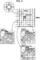
- Fig. 2 graphically depicts exemplary allocation of weights to the cells.
- respective sides of each cell are identified by symbols W1, W2, W3, and W4, which exemplify the left or west side, the right or east side, the upper or north side, and the lower or south side, respectively.
- the cell passing routes may include left turn, straight travel, and right turn.
- left turn may include passage of the side W3
- straight travel may include passage of the side W2
- right turn may include passage of the side W4.
- Each of the cells may thus be provided with weights given to travels for three passing routes of left turn, straight travel, and right travel, for each of the four sides to be entered.
- Fig. 2 depicts, in a matrix form, exemplary weights given to travels which are allocated to one of the outer end cells in contact with the boundary with the outside, one of obstacle adjacent cells located adjacent to an obstacle cell including an obstacle, and one of ordinary cells.
- the cells obtained by mesh generation may be indicated by Cmn as a matrix of m x n.
- one of the outer end cells having an entry position at the side W1 has a weight "0.8" given to straight travel with an exit position at the side W2, a weight "0.2” given to left turn with an exit position at the side W3, and a weight "0” given to right turn with an exit position at the side W4.
- Straight travel which may be regarded as achieving high work efficiency in this case, has the higher weight in this example shown in Fig. 2 .
- right turn at this cell causes the work vehicle to travel beyond the boundary and is thus prohibited with the weight "0".
- a case with an entry position at the side W2 in this example is similar to the case with the entry position at the side W1.
- Straight travel is prohibited in a case with an entry position at the side W3.
- one of the obstacle adjacent cells has weights given to travels similar to those of the outer end cells, including the weight "0" given to a cell passing route of entering the obstacle cell.
- An obstacle in the work field is avoided in principle during travel.
- a high weight is thus allocated in this example to a cell passing route of surrounding the obstacle cell.
- Fig. 2 exemplifies the case with the entry position at the side W1.
- straight travel with the exit position at the side W2 leads to travel of surrounding the obstacle cell and thus has the high weight "0.8".
- right turn with the exit position at the side W4 in this example leads to travel to be distant from the obstacle cell and thus has the low weight "0.2".
- the entry position at the side W3 is impossible in this example and disregarded, and is thus indicated by the symbol "-".
- Free cells including neither outer end cells nor obstacle adjacent cells can have equal weights given to travels. Under a precondition of prioritizing straight travel in this case, a cell passing route of straight travel is higher in weight than cell passing routes of left turn and right turn.
- the weighting changer 64 may change the weights given to travels allocated by the travel weighting allocator 62.
- Causes for change of the weights given to travels by the weighting changer 64 may include a travel condition of prohibiting or avoiding as much as possible reentry to an already passed cell. Specifically, when the adjacent cell is already passed, a cell passing route of entering the already passed cell may have a weight changed to "0" or approximated to "0".
- the causes may also include a travel condition of considering a travel locus involving a plurality of cells continuously passed to reach a cell to be evaluated. In a case where the latest travel has a straight locus in an area prioritizing straight travel, the weights given to travels may be changed to continue straight travel as much as possible. In another case where the latest travel has a turn travel locus in an area often covered by U-turn travel or right-angle turn travel, the weights given to travels may be changed to continue turn travel as much as possible.
- the travel route generator 65 may connect the cell passing routes sequentially determined by the cell passing route determiner 63 to generate a travel route for actual travel in the work field by the work vehicle.
- the cell manager 61 may be configured to calculate time for passing each cell by left turn, time for passing the cell by straight travel, and time for passing the cell by right turn, in accordance with set vehicle speed, and manage the time.
- the cell manager 61 may thus also be configured to integrate the time for passing the cells configuring a finally generated travel route, to calculate halfway travel elapsed time or travel end time for the work vehicle traveling on the travel route.
- Fig. 3 depicts a tractor exemplifying a work vehicle configured to travel in a manned or unmanned state along a travel route generated by the route generating device described above.
- This exemplary tractor is equipped with, as a work device 30, a rotary tiller configured to till a field (e.g. work field) bordered with a ridge.
- the exemplary tractor is provided with an operation unit 20 at a center portion of a vehicle body 1 supported by front wheels 11 and rear wheels 12.
- the vehicle body 1 may have a rear portion supporting the work device 30 vertically shiftable via a hydraulic lifting mechanism 31.
- the front wheels 11 may function as steering control wheels, and the tractor may be redirected by changing a steering angle of the front wheels.
- the steering angle of the front wheels 11 may be changed by actuating a steering mechanism 13.
- the steering mechanism 13 may include a steering motor 14 for automatic steerage.
- the front wheels 11 can be controlled by operating a steering wheel 22 disposed at the operation unit 20 during manual travel.
- the exemplary tractor has a cabin 21 provided with a satellite positioning module 80 configured as a GNSS module.
- Constituent elements of the satellite positioning module 80 may include a satellite antenna configured to receive GPS signals and GNSS signals and attached to a ceiling area of the cabin 21.
- the satellite positioning module 80 can include an inertial navigation module provided with a gyro acceleration sensor and a magnetic direction sensor in order for complementation of satellite navigation.
- the inertial navigation module can alternatively be disposed at a location different from the satellite positioning module 80.
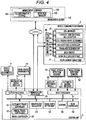
- Fig. 4 depicts an exemplary control system that may be mounted on the tractor, and an exemplary control system of a mobile communication terminal 4 that may be carried by a supervisor (e.g. driver) supervising drive operation of the tractor.
- the mobile communication terminal 4 may be provided with a route generation module 6 obtained by modularizing the route generating device described with reference to Figs. 1 and 2 .
- the route generation module 6 thus may basically include the cell manager 61, the travel weighting allocator 62, the cell passing route determiner 63, the weighting changer 64, the travel route generator 65, the work field data input unit 67, and/or the mesh divider 66. These units may have the basic functions described above.
- the mobile communication terminal 4 may include the route generation module 6, as well as various functional units of an ordinary computer system, like a communication controller 40 and a display unit.
- the mobile communication terminal 4 may be connectable with a control unit 5 as a core element in the control system of the tractor, so as to achieve data exchange by wireless or wired communication.
- the mobile communication terminal 4 may further be configured to exchange data through a wireless line or the Internet, with a management computer 100 provided in a remote management center KS.
- the management computer 100 may include a field information storage 101 storing field information including the topographical map of a field as a work field, field attribute information, and the like, which may be necessary for generation of a travel route by the route generation module 6.
- the field information may include an entrance-exit port of the field, ground tilts of the field, a position of an obstacle in the field, and the like.
- the management computer 100 may further include a work plan manager 102 configured to manage a work plan document describing travel work in a designated field.
- the mobile communication terminal 4 may access the management computer 100, to sample and download field information on the field as a work target, from the field information storage 101.
- the work field data input unit 67 may receive a downloaded outline view of the field.
- the control unit 5 as the core element of the control system of the tractor may include an output processor 7 and an input processor 8, which may function as an input and output interface, and a communication processor 70.
- the output processor 7 may be connected to vehicle travel instruments 71, work device instruments 72, a notification device 73, and the like, which may be mounted on the tractor.
- the vehicle travel instruments 71 may include, but are not limited to, the steering motor 14, and instruments to be controlled for vehicle travel, such as a transmission mechanism and an engine unit (not depicted).
- the work device instruments 72 may include, but are not limited to, a drive mechanism for the work device 30, the lifting mechanism 31 configured to vertically shift the work device, and the like.
- the notification device 73 may include a display, a lamp, and/or a speaker.
- the display may particularly display the outline of the field, as well as various notification information on an already passed travel route (e.g. a travel locus), a travel route to be covered, and the like.
- the lamp and/or the speaker may be used to notify the driver or the supervisor of caution information and/or warning information such as travel precaution and/or deviation from a target travel route during automatic steering travel.
- the communication processor 70 may have a function of transmitting data processed by the control unit 5 to the management computer 100 and receiving various types of data from the management computer 100.
- the input processor 8 may be connected to, the satellite positioning module 80, travel system detection sensors 81, work system detection sensors 82, an automatic/manual switcher 83, and the like.
- the travel system detection sensors 81 may include, but are not limited to, a sensor configured to detect a travel state such as engine rotational speed or a transmission state.
- the work system detection sensors 82 may include, but are not limited to, a sensor configured to detect a position and/or a tilt of the work device 30, a sensor configured to detect a workload, and the like.
- the automatic/manual switcher 83 may be configured to select either an automatic travel mode for automatic steering travel or a manual steering mode for manual steering travel.
- the control unit 5 may further include a travel controller 50, a work controller 54, an own position calculator 53, a travel route setting unit 55, and/or a notifier 56.
- the own position calculator 53 may calculate an own position in accordance with positioning data transmitted from the satellite positioning module 80.
- This exemplary tractor is configured to travel both in the automatic travel (e.g. automatic steering) mode and the manual travel (e.g. manual steering) mode, the travel controller 50 configured to control the vehicle travel instruments 71 may include a manual travel controller 51 and an automatic travel controller 52.
- the manual travel controller 51 may control the vehicle travel instruments 71 in accordance with operation of the driver.
- the automatic travel controller 52 may calculate directional deviation and/or positional deviation between the travel route set by the travel route setting unit 55 and the own position, generate an automatic steering command, and transmit the generated automatic steering command to the steering motor 14 via the output processor 7.
- the work controller 54 may transmit a control signal to the work device instruments 72 in order to control operation of the work device 30.
- the notifier 56 may generate a notification signal (e.g. display data and/or voice data) for notification to the driver or the supervisor of necessary information through the notification device 73 including the display and the like.
- the travel route setting unit 55 may receive the travel route generated by the route generation module 6 from mobile communication terminal 4 via the communication processor 70, and set the received travel route as a target travel route.
- the tractor may be driven to a start point indicated on the travel route upon start of work. The tractor may then be made to travel along the set travel route automatically or manually.
- Fig. 5 Described next with reference to Fig. 5 is exemplary travel route generation processing of mesh-dividing the filed, allocating weights given to travels to each of obtained cells, and searching for a travel route in accordance with the weights given to travels.
- the work field data input unit 67 may sample the outline from the received topographical map of the field, and develop the outline in a working area of the mesh divider 66.
- the approximated rectangle may be divided into a large number of cells with meshes parallel to the sides of the approximated rectangle and each having a side with a value (e.g. travel work width) obtained by subtracting a predetermined overlapping amount from the work width of the work device 30.
- a value e.g. travel work width
- an area having a predetermined width (e.g. obtained by integral multiplication of the travel work width) from the outer periphery may be determined as headland for turn, parking, and the like of the tractor.
- a travel route for formation of the headland may be a peripheral travel route for travel along the outline and typically counterclockwise. A plurality of times of entry to and travel on the peripheral travel route already covered may be allowed exceptionally. If work requires no consideration of formation of the peripheral travel route, this step may be excluded.
- the field information downloaded from the management computer 100 may include positional data on the entrance-exit port of the field, and a cell corresponding to the position of the tractor entered through the entrance-exit port may be regarded as the start point cell and an end point cell.
- the weights given to travels described with reference to Fig. 2 may be allocated to the cells located inside the peripheral travel route (e.g. headland).
- the field information includes obstacle data on a position of an untravelable site having an obstacle or the like
- cells belonging to the untravelable site may be regarded as obstacle cells (e.g. untravelable cells) and may not be provided with weights given to travels.
- the cells configuring the entire field can be treated as matrix elements [C11 to C1n, ... and Cm1 to Cmn], which may allow easy designation of a specific cell.
- the weights given to travels which are allocated to the cells can also be treated as matrix elements (e.g. vectors) as described above.
- the weights given to travels at each of the cells may be calculated in accordance with a positional relation with the obstacle cell, a positional relation with the peripheral travel route and/or a basic travel pattern (e.g. prioritizing long straight travel, prioritizing spiral travel, prioritizing a specific turn direction, or the like), and the calculated weights given to travels may be allocated to the cell.
- cell passing routes may be sequentially determined from the start point cell with reference to the weights given to travels.
- the weighting changer 64 may change the weights given to travels at a specific cell influenced by passage of other cells.
- backtracking may be executed to return to the most recently passed cell for selection of a different passing route and search for a different travel route.
- the cell passing routes may be connected in order of the determination for generation of a travel route.
- Time for travel on the generated travel route may be calculated, inclusive of halfway elapsed time.
- Such generation of a travel route can be executed only once or a plurality of times. Weights given to travels at each of the cells may be calculated again in accordance with a changed basic travel pattern, and cell passing routes may be determined again in accordance with the revised weights given to travels. If there is generated a plurality of travel routes, the travel route having the shortest travel time can be selected for improved work efficiency.
- the present invention is applicable to a work vehicle that works in a work field along a set travel route.
- the work vehicle can travel along the travel route either manually or automatically.
Landscapes
- Engineering & Computer Science (AREA)
- Radar, Positioning & Navigation (AREA)
- Remote Sensing (AREA)
- Automation & Control Theory (AREA)
- Physics & Mathematics (AREA)
- General Physics & Mathematics (AREA)
- Aviation & Aerospace Engineering (AREA)
- Life Sciences & Earth Sciences (AREA)
- Soil Sciences (AREA)
- Environmental Sciences (AREA)
- Mechanical Engineering (AREA)
- Control Of Position, Course, Altitude, Or Attitude Of Moving Bodies (AREA)
- Guiding Agricultural Machines (AREA)
- Traffic Control Systems (AREA)
Abstract
Description
- The present invention relates to a travel route generating device configured to generate a travel route for a work vehicle that works while traveling in a work field.
-
JP 2008-67617 A -
US 6,728,607 B1 discloses a travel route generation system configured to generate a travel route achieving minimized energy consumption. This system initially estimates levels of energy necessary for passing cells obtained by mesh-dividing a work field in accordance with altitudes of the cells, and allocates, to the cells, numerical values indicating the estimated energy levels. The system subsequently applies the cells to a plurality of planned travel routes for a work vehicle in the work field, compares sums of the necessary energy levels for travel along the planned travel routes, and adopts the travel route having the lowest sum of the energy levels as an actual travel route. The travel route generation system is configured to compare the different travel routes by calculating the sums of the energy levels for the travel along the planned travel routes. The system is, however, not configured to plan the travel routes themselves.US 6,728,607 B1 merely suggests two types of travel routes including a plurality of parallel straight routes extending in the east-west direction or in the south-north direction and U-turn routes each connecting the straight routes adjacent to each other. - In view of the above actual circumstances, it is an object of the present invention to provide a technique for generating a travel route that appropriately passes a large number of cells obtained by mesh-dividing a work field.
- According to an aspect, a travel route generating device configured to generate a travel route for a work vehicle that works while traveling in a work field is provided. The travel route generating device includes: a cell manager configured to manage a plurality of cells obtained by generating meshes in a topographical map of the work field at a predetermined interval; a travel weighting allocator configured to allocate to one of the cells, as weights given to travels, a weight given to left-turn travel, a weight given to straight travel, and a weight given to right-turn travel, the weights each indicating a travel effect degree in each cell passing direction upon travel from the cell to one of cells adjacent thereto; a cell passing route determiner configured to determine a cell passing route of passing the cell in accordance with the weight given to the left-turn travel, the weight given to the straight travel, and the weight given to the right-turn travel allocated to the cell; a weighting changer configured to change the weights given to travels which are allocated to a cell influenced by passage of the cell; and a travel route generator configured to generate the travel route by connecting the cell passing routes sequentially determined by the cell passing route determiner.
In various embodiments and examples described herein, the "plurality of cells obtained by generating meshes in a topographical map of the work field at a predetermined interval" may be a large number of cells. The "large number of cells" may be understood as indicating a number of cells that represent the work field with sufficient granularity to generate the travel route. - In this configuration, the weights may be allocated in accordance with manners of passing the cells obtained by mesh generation (e.g. passing by left turn, by straight travel, and by right turn etc.). Left turn, straight travel, and right turn in each of the cells may differ from one another dependently on a position of entry to the cell. The weights of the cell may be allocated in each direction of entry to the cell. Exemplarily assume that an entry direction from the west to the east is called a first entry direction, an entry direction from the east to the west is called a second entry direction, an entry direction from the north to the south is called a third entry direction, and an entry direction from the south to the north is called a fourth entry direction. A weight given to left turn, a weight given to straight travel, and a weight given to right turn may be allocated in each of the four entry directions, so that at most twelve weights can be allocated to each of the cells. The cell passing route determiner may sequentially evaluate the weights allocated to each entered cell, and determine a passing route (e.g. left turn, straight travel, or right turn) of the cell. The cell passing routes sequentially determined by the cell passing route determiner may be connected to generate a target travel route for the work vehicle traveling in the work field. A desired travel route may be generated by preliminarily setting weights given to travels which define the desired travel route. The work vehicle may travel along the targeted work route in a manned or unmanned state. The travel route generating device may generate a desired travel route if a travel route planner preliminarily sets weights given to travels which are appropriate for the cells obtained by mesh generation as reference information indicating how the work vehicle should pass the work field (e.g. straight routes elongated in the east-west direction or in the south-north direction, and a spiral route mainly including turn travel route etc.).
- Thus, in some circumstances, the travel route generating device according to the above-stated aspect may facilitate generation of a travel route that is appropriate for each work field. This may lead to improving efficiency of the work to be performed by the work vehicle in the work field.
- The work vehicle may need to travel all over the work field depending on a type of work. It may be important to minimize unpassed cells upon generation of a travel route for the work vehicle. In view of this, in some examples, the cell manager may be further configured to execute backtracking when the route reaches a dead end with the cells including an unpassed cell. The cell manager may designate again a cell passed before entry to the dead-end cell, and sets to select a route other than the cell passing route determined last time as a route passing the cell. The backtracking may be executed until a new passable cell is found. The backtracking may contribute to covering as much area as possible within the work field by the generated travel route.
- The periphery of the work field may be bordered with a fence, a ridge, or the like, to prohibit travel to outside the work field. It may also be prohibited from approaching any obstacle like a rock, a tree, or a utility pole in the work field. Such travel prohibition can be achieved by not selecting a cell passing route including entry to a cell within a travel prohibited area, for example, setting the weight of such a cell passing route to "zero" (e.g. selection prohibited). In view of this, in some examples, the weights given to travels allocated by the travel weighting allocator may include weights given to prohibition of travel out of the work field and travel to an obstacle located in the work field. This may enable generation of a travel route that stays within the work field and that avoids the obstacle, which may lead to efficient work performed by the work vehicle.
- An agricultural work vehicle typically travels in a field as a work field efficiently by repeating straight travel as long as possible. Such travel can be achieved by allocating, to the cells not in a peripheral area, higher weights for straight travel than those for left turn and right turn. In view of this, in some examples, the weights given to travels allocated by the travel weighting allocator may include a weight prioritizing the straight travel. This may further contribute to improving efficiency of the work to be performed by the work vehicle.
- In some circumstances, certain work does not allow the work vehicle to travel in an area already traveled once for work or requires the work vehicle to travel the area as less as possible. In view of this, in some examples, the weighting changer may be further configured to change the weights given to travels for prohibition of cell passing travel including entry to an already passed cell. In some cases, the weighting changer may prohibit a cell passing route including entry to an already passed cell while allocating, to the cell passing route, a much lower weight than those of other cell passing routes. This may further contribute to improving efficiency of the work to be performed by the work vehicle.
- Determination of a cell passing route at the entered cell in the travel of the work vehicle may be dependent on the cell passing route at the previously passed cell or at the further previously passed cell. In an area often covered by U-turn travel, right-angle turn travel, or the like, the weight at the entered cell may be favorably changed in accordance with a travel locus just before the entry, to prioritize such turn travel. In view of this, in some examples, the weighting changer may further be configured to change the weights given to travels which are allocated to the cell in accordance with a travel locus involving a plurality of cells continuously passed to reach the cell. This may further facilitate efficient generation of a travel route that is appropriate for the work field.
- In some circumstances, certain work travel requires the work vehicle to cover the front of the work field with a work width of a mounted work device. In order to satisfy such a work specification, in some examples, the interval at which the meshes are generated may be set to a work width of the work vehicle or a work width obtained from the work width of the work vehicle in consideration of a predetermined overlapping amount. The work vehicle can thus work in all over the work field by generating the travel route including travel to all the cells and traveling along the travel route.
- In some circumstances, a certain work field has an entrance and an exit restricted for the work vehicle. In such a case, the work vehicle may need to generate a travel route having a start point at a cell corresponding to the entrance and an end point at a cell corresponding to the exit. In view of this, in some examples, the travel route may have a start point cell and an end point cell corresponding to an entrance-exit port of the work field. This may enable generation of a travel route with starting and end points corresponding to the entrance and the exit of the work field.
- According to another aspect, a computer-implemented method is provided for generating a travel route for a work vehicle that works while traveling in a work field. The method may comprise:
- generating meshes in a topographical map of the work field at a predetermined interval to obtain a plurality of cells;
- allocating to one of the cells, as weights given to travels, a weight given to left-turn travel, a weight given to straight travel, and a weight given to right-turn travel, the weights each indicating a travel effect degree in each cell passing direction upon travel from the cell to one of cells adjacent thereto;
- determining a cell passing route of passing the cell in accordance with the weight given to the left-turn travel, the weight given to the straight travel, and the weight given to the right-turn travel allocated to the cell;
- changing the weights given to travels which are allocated to a cell influenced by passage of the cell; and
- generating the travel route by connecting the cell passing routes sequentially determined by the cell passing route determiner.
- According to yet another aspect, a computer program product is provided. The computer program product may comprise computer-readable instructions that, when loaded and run on a computer, cause the computer to perform the method according to the above-stated aspect.
- The subject matter described in the application can be implemented as a method or as a system, possibly in the form of one or more computer program products. The subject matter described in the application can be implemented in a data signal or on a machine readable medium, where the medium is embodied in one or more information carriers, such as a CD-ROM, a DVD-ROM, a semiconductor memory, or a hard disk. Such computer program products may cause a data processing apparatus to perform one or more operations described in the application.
- In addition, subject matter described in the application can also be implemented as a system including a processor, and a memory coupled to the processor. The memory may encode one or more programs to cause the processor to perform one or more of the methods described in the application. Further subject matter described in the application can be implemented using various machines.
- Details of one or more implementations are set forth in the exemplary drawings and description below. Other features will be apparent from the description, the drawings, and from the claims. It should be understood, however, that even though embodiments are separately described, single features of different embodiments may be combined to further embodiments.
-
Fig. 1 is a configuration diagram of an exemplary route generating device. -
Fig. 2 is an explanatory view of allocation of weights given to travels to mesh-divided cells. -
Fig. 3 is a side view of a tractor exemplifying a work vehicle configured to travel in a manned or unmanned state along a travel route generated by the route generating device. -
Fig. 4 is a functional block diagram depicting exemplary basic control functions of a mobile communication terminal as the route generating device and the tractor. -
Fig. 5 is a flowchart exemplifying a travel route generation procedure. -
Fig. 1 is a configuration diagram of an exemplary travel route generating device configured to generate a travel route for a work vehicle that works while traveling in a work field. The exemplary travel route generating device may initially divide a work field with meshes into a large number of cells. The travel route generating device may allocate a weight given to each cell passing route of passing the divided cells, e.g., each of a left-turn route, a straight travel route, and a right-turn route, and sequentially determine cell passing routes of passing the cells in accordance with the weights. The travel route generating device may generate a travel route for the work vehicle by sequentially connecting the determined cell passing routes. The initially allocated weights may be changed if the determined cell passing routes influence the weights. The travel route generating device may thus include basic functional units of acell manager 61, atravel weighting allocator 62, a cell passingroute determiner 63, aweighting changer 64, and atravel route generator 65. The travel route generating device may be substantially configured by a computer system configured to execute computer simulation. Each of the functional units may execute a program to achieve a specific function, and can alternatively be structured at least partially by hardware. -
Fig. 1 exemplifies the travel route generating device including, as a data input unit, a work fielddata input unit 67 configured to receive, from outside, topographical map data including an outline of the work field. The travel route generating device may include amesh divider 66 configured to approximate the outline of the work field provided from the work fielddata input unit 67 to a circumscribing rectangle, and mesh-divide the circumscribing rectangle by a side length (e.g. a predetermined interval) obtained from a work width of the work vehicle in consideration of overlap. The work field may have outer end cells treated as special cells prohibiting passage to outside the work field. Thecell manager 61 may manage cell passing simulation of sequentially passing a large number of cells obtained by mesh generation. - If there is any travel pattern to be prioritized (e.g. repeated straight travel in the east-west direction or spiral travel etc.) in accordance with the topographical map of the work field and attribute information on the work field (e.g. ground tilts and a type of work), the
cell manager 61 may command allocation of weights to the cells so as to prioritize the travel pattern. If the attribute information includes positional information on an obstacle disturbing travel, thecell manager 61 may command allocation of weights to the cells so as to prohibit travel to the obstacle. Thecell manager 61 may designate a start point cell as a start point of the travel route. - The
travel weighting allocator 62 may allocate, to each of the cells, weights, e.g., a weight given to left-turn travel, a weight given to straight travel, and a weight given to right-turn travel, indicative of travel effect degrees in respective cell passing directions upon travel from a cell to one of the cells adjacent thereto, in accordance with the command from thecell manager 61. These weights can be indicated by numerical values or symbols. The weights treated as probability values may each have a numerical value from zero to one. The cell passingroute determiner 63 may determine how to pass the entered cell in accordance with the weights allocated to the cell. The cell passingroute determiner 63 may determine a cell passing route in accordance with the easiest manner of selecting the cell passing route having the weight with a large value. When determination is made in accordance with such probability, a cell passing route may be determined probabilistically in accordance with the weight as a probability value allocated to each cell passing route. In this case, a cell passing route having a higher probability value is more likely to be selected but is not necessarily selected. -
Fig. 2 graphically depicts exemplary allocation of weights to the cells. As depicted inFig. 2 , respective sides of each cell are identified by symbols W1, W2, W3, and W4, which exemplify the left or west side, the right or east side, the upper or north side, and the lower or south side, respectively. The cell passing routes may include left turn, straight travel, and right turn. In an exemplary case where a cell passing route enters the side W1, left turn may include passage of the side W3, straight travel may include passage of the side W2, and right turn may include passage of the side W4. Each of the cells may thus be provided with weights given to travels for three passing routes of left turn, straight travel, and right travel, for each of the four sides to be entered. -
Fig. 2 depicts, in a matrix form, exemplary weights given to travels which are allocated to one of the outer end cells in contact with the boundary with the outside, one of obstacle adjacent cells located adjacent to an obstacle cell including an obstacle, and one of ordinary cells. The cells obtained by mesh generation may be indicated by Cmn as a matrix of m x n. Each of the cells may have weights given to travels indicated by a matrix W(Cmn) = [Wij] mn, 1 ≤ i ≤ 4, 1 ≤ j ≤ 4, as apparent from charts inFig. 2 . - Specifically, in
Fig. 2 , one of the outer end cells having an entry position at the side W1 has a weight "0.8" given to straight travel with an exit position at the side W2, a weight "0.2" given to left turn with an exit position at the side W3, and a weight "0" given to right turn with an exit position at the side W4. Straight travel, which may be regarded as achieving high work efficiency in this case, has the higher weight in this example shown inFig. 2 . Further, in this example, right turn at this cell causes the work vehicle to travel beyond the boundary and is thus prohibited with the weight "0". A case with an entry position at the side W2 in this example is similar to the case with the entry position at the side W1. Straight travel is prohibited in a case with an entry position at the side W3. Right turn and left turn thus equally have a weight "0.5". When the cell has equal weights, determination can be made in accordance with preset priority ranking or random numbers. An entry position at the side W4 is impossible in this example and disregarded, which is thus indicated by a symbol "-". Cases where the entry position is identical with the exit position are disregarded at all the cells in this example and are thus indicated by the symbol "-". - In the example shown in
Fig. 2 , one of the obstacle adjacent cells has weights given to travels similar to those of the outer end cells, including the weight "0" given to a cell passing route of entering the obstacle cell. An obstacle in the work field is avoided in principle during travel. A high weight is thus allocated in this example to a cell passing route of surrounding the obstacle cell.Fig. 2 exemplifies the case with the entry position at the side W1. In this example, straight travel with the exit position at the side W2 leads to travel of surrounding the obstacle cell and thus has the high weight "0.8". In contrast, right turn with the exit position at the side W4 in this example leads to travel to be distant from the obstacle cell and thus has the low weight "0.2". The entry position at the side W3 is impossible in this example and disregarded, and is thus indicated by the symbol "-". - Free cells including neither outer end cells nor obstacle adjacent cells can have equal weights given to travels. Under a precondition of prioritizing straight travel in this case, a cell passing route of straight travel is higher in weight than cell passing routes of left turn and right turn.
- The
weighting changer 64 may change the weights given to travels allocated by thetravel weighting allocator 62. Causes for change of the weights given to travels by theweighting changer 64 may include a travel condition of prohibiting or avoiding as much as possible reentry to an already passed cell. Specifically, when the adjacent cell is already passed, a cell passing route of entering the already passed cell may have a weight changed to "0" or approximated to "0". The causes may also include a travel condition of considering a travel locus involving a plurality of cells continuously passed to reach a cell to be evaluated. In a case where the latest travel has a straight locus in an area prioritizing straight travel, the weights given to travels may be changed to continue straight travel as much as possible. In another case where the latest travel has a turn travel locus in an area often covered by U-turn travel or right-angle turn travel, the weights given to travels may be changed to continue turn travel as much as possible. - The
travel route generator 65 may connect the cell passing routes sequentially determined by the cell passingroute determiner 63 to generate a travel route for actual travel in the work field by the work vehicle. Thecell manager 61 may be configured to calculate time for passing each cell by left turn, time for passing the cell by straight travel, and time for passing the cell by right turn, in accordance with set vehicle speed, and manage the time. Thecell manager 61 may thus also be configured to integrate the time for passing the cells configuring a finally generated travel route, to calculate halfway travel elapsed time or travel end time for the work vehicle traveling on the travel route. -
Fig. 3 depicts a tractor exemplifying a work vehicle configured to travel in a manned or unmanned state along a travel route generated by the route generating device described above. This exemplary tractor is equipped with, as awork device 30, a rotary tiller configured to till a field (e.g. work field) bordered with a ridge. The exemplary tractor is provided with anoperation unit 20 at a center portion of a vehicle body 1 supported byfront wheels 11 andrear wheels 12. The vehicle body 1 may have a rear portion supporting thework device 30 vertically shiftable via ahydraulic lifting mechanism 31. Thefront wheels 11 may function as steering control wheels, and the tractor may be redirected by changing a steering angle of the front wheels. The steering angle of thefront wheels 11 may be changed by actuating asteering mechanism 13. Thesteering mechanism 13 may include asteering motor 14 for automatic steerage. Thefront wheels 11 can be controlled by operating asteering wheel 22 disposed at theoperation unit 20 during manual travel. The exemplary tractor has acabin 21 provided with asatellite positioning module 80 configured as a GNSS module. Constituent elements of thesatellite positioning module 80 may include a satellite antenna configured to receive GPS signals and GNSS signals and attached to a ceiling area of thecabin 21. Thesatellite positioning module 80 can include an inertial navigation module provided with a gyro acceleration sensor and a magnetic direction sensor in order for complementation of satellite navigation. The inertial navigation module can alternatively be disposed at a location different from thesatellite positioning module 80. -
Fig. 4 depicts an exemplary control system that may be mounted on the tractor, and an exemplary control system of amobile communication terminal 4 that may be carried by a supervisor (e.g. driver) supervising drive operation of the tractor. Themobile communication terminal 4 according to this embodiment may be provided with aroute generation module 6 obtained by modularizing the route generating device described with reference toFigs. 1 and2 . Theroute generation module 6 thus may basically include thecell manager 61, thetravel weighting allocator 62, the cell passingroute determiner 63, theweighting changer 64, thetravel route generator 65, the work fielddata input unit 67, and/or themesh divider 66. These units may have the basic functions described above. - The
mobile communication terminal 4 may include theroute generation module 6, as well as various functional units of an ordinary computer system, like acommunication controller 40 and a display unit. Themobile communication terminal 4 may be connectable with a control unit 5 as a core element in the control system of the tractor, so as to achieve data exchange by wireless or wired communication. Themobile communication terminal 4 may further be configured to exchange data through a wireless line or the Internet, with amanagement computer 100 provided in a remote management center KS. Themanagement computer 100 according to this embodiment may include afield information storage 101 storing field information including the topographical map of a field as a work field, field attribute information, and the like, which may be necessary for generation of a travel route by theroute generation module 6. The field information may include an entrance-exit port of the field, ground tilts of the field, a position of an obstacle in the field, and the like. Themanagement computer 100 may further include awork plan manager 102 configured to manage a work plan document describing travel work in a designated field. Themobile communication terminal 4 may access themanagement computer 100, to sample and download field information on the field as a work target, from thefield information storage 101. The work fielddata input unit 67 may receive a downloaded outline view of the field. - The control unit 5 as the core element of the control system of the tractor may include an output processor 7 and an
input processor 8, which may function as an input and output interface, and a communication processor 70. The output processor 7 may be connected tovehicle travel instruments 71,work device instruments 72, anotification device 73, and the like, which may be mounted on the tractor. Thevehicle travel instruments 71 may include, but are not limited to, thesteering motor 14, and instruments to be controlled for vehicle travel, such as a transmission mechanism and an engine unit (not depicted). Thework device instruments 72 may include, but are not limited to, a drive mechanism for thework device 30, thelifting mechanism 31 configured to vertically shift the work device, and the like. Thenotification device 73 may include a display, a lamp, and/or a speaker. The display may particularly display the outline of the field, as well as various notification information on an already passed travel route (e.g. a travel locus), a travel route to be covered, and the like. The lamp and/or the speaker may be used to notify the driver or the supervisor of caution information and/or warning information such as travel precaution and/or deviation from a target travel route during automatic steering travel. The communication processor 70 may have a function of transmitting data processed by the control unit 5 to themanagement computer 100 and receiving various types of data from themanagement computer 100. - The
input processor 8 may be connected to, thesatellite positioning module 80, travelsystem detection sensors 81, worksystem detection sensors 82, an automatic/manual switcher 83, and the like. The travelsystem detection sensors 81 may include, but are not limited to, a sensor configured to detect a travel state such as engine rotational speed or a transmission state. The worksystem detection sensors 82 may include, but are not limited to, a sensor configured to detect a position and/or a tilt of thework device 30, a sensor configured to detect a workload, and the like. The automatic/manual switcher 83 may be configured to select either an automatic travel mode for automatic steering travel or a manual steering mode for manual steering travel. - The control unit 5 may further include a
travel controller 50, awork controller 54, anown position calculator 53, a travelroute setting unit 55, and/or a notifier 56. Theown position calculator 53 may calculate an own position in accordance with positioning data transmitted from thesatellite positioning module 80. This exemplary tractor is configured to travel both in the automatic travel (e.g. automatic steering) mode and the manual travel (e.g. manual steering) mode, thetravel controller 50 configured to control thevehicle travel instruments 71 may include amanual travel controller 51 and anautomatic travel controller 52. Themanual travel controller 51 may control thevehicle travel instruments 71 in accordance with operation of the driver. Theautomatic travel controller 52 may calculate directional deviation and/or positional deviation between the travel route set by the travelroute setting unit 55 and the own position, generate an automatic steering command, and transmit the generated automatic steering command to thesteering motor 14 via the output processor 7. Thework controller 54 may transmit a control signal to thework device instruments 72 in order to control operation of thework device 30. The notifier 56 may generate a notification signal (e.g. display data and/or voice data) for notification to the driver or the supervisor of necessary information through thenotification device 73 including the display and the like. - The travel
route setting unit 55 may receive the travel route generated by theroute generation module 6 frommobile communication terminal 4 via the communication processor 70, and set the received travel route as a target travel route. The tractor may be driven to a start point indicated on the travel route upon start of work. The tractor may then be made to travel along the set travel route automatically or manually. - Described next with reference to
Fig. 5 is exemplary travel route generation processing of mesh-dividing the filed, allocating weights given to travels to each of obtained cells, and searching for a travel route in accordance with the weights given to travels. - The work field
data input unit 67 may sample the outline from the received topographical map of the field, and develop the outline in a working area of themesh divider 66. - There may be generated an approximated rectangle circumscribing the sampled outline of the field.
- The approximated rectangle may be divided into a large number of cells with meshes parallel to the sides of the approximated rectangle and each having a side with a value (e.g. travel work width) obtained by subtracting a predetermined overlapping amount from the work width of the
work device 30. - In tilling work by the tractor, an area having a predetermined width (e.g. obtained by integral multiplication of the travel work width) from the outer periphery may be determined as headland for turn, parking, and the like of the tractor. A travel route for formation of the headland may be a peripheral travel route for travel along the outline and typically counterclockwise. A plurality of times of entry to and travel on the peripheral travel route already covered may be allowed exceptionally. If work requires no consideration of formation of the peripheral travel route, this step may be excluded.
- The field information downloaded from the
management computer 100 may include positional data on the entrance-exit port of the field, and a cell corresponding to the position of the tractor entered through the entrance-exit port may be regarded as the start point cell and an end point cell. - According to this embodiment, the weights given to travels described with reference to
Fig. 2 may be allocated to the cells located inside the peripheral travel route (e.g. headland). In a case where the field information includes obstacle data on a position of an untravelable site having an obstacle or the like, cells belonging to the untravelable site may be regarded as obstacle cells (e.g. untravelable cells) and may not be provided with weights given to travels. The cells configuring the entire field can be treated as matrix elements [C11 to C1n, ... and Cm1 to Cmn], which may allow easy designation of a specific cell. The weights given to travels which are allocated to the cells can also be treated as matrix elements (e.g. vectors) as described above. In a case where the weights given to travels are configured as depicted inFig. 2 , weights given to travels at a specific cell may be expressed by W(Cmn) = [Wij] mn, 1 ≤ i ≤4, 1 ≤ j ≤ 4. The weights given to travels at each of the cells may be calculated in accordance with a positional relation with the obstacle cell, a positional relation with the peripheral travel route and/or a basic travel pattern (e.g. prioritizing long straight travel, prioritizing spiral travel, prioritizing a specific turn direction, or the like), and the calculated weights given to travels may be allocated to the cell. - When the weights given to travels are allocated to all the cells, cell passing routes may be sequentially determined from the start point cell with reference to the weights given to travels. The
weighting changer 64 may change the weights given to travels at a specific cell influenced by passage of other cells. When the route reaches a dead end although there is any unpassed cell, backtracking may be executed to return to the most recently passed cell for selection of a different passing route and search for a different travel route. - When cell passing routes of all the cells to be passed are determined, the cell passing routes may be connected in order of the determination for generation of a travel route. Time for travel on the generated travel route may be calculated, inclusive of halfway elapsed time.
- Such generation of a travel route can be executed only once or a plurality of times. Weights given to travels at each of the cells may be calculated again in accordance with a changed basic travel pattern, and cell passing routes may be determined again in accordance with the revised weights given to travels. If there is generated a plurality of travel routes, the travel route having the shortest travel time can be selected for improved work efficiency.
-
- (1) The above embodiment assumes that the single work vehicle (e.g. tractor) executes work on the work field (e.g. field). The present invention may be also applicable to generation of travel routes for work executed by a plurality of work vehicles. Management of time for passing the cells by each of the work vehicles may achieve generation of travel routes for cooperative travel by the plurality of work vehicles traveling together on the work field.
- (2) The exemplary functional units in the functional block diagram depicted in
Fig. 4 are classified mainly for convenience of the description. Each of the functional units can be integrated with a different one of the functional units, or can be divided into a plurality of functional units. For example, theroute generation module 6 can be provided at themanagement computer 100, and the generated travel route can be downloaded to the control unit 5 of the work vehicle. Theroute generation module 6 can still alternatively be provided at the control unit 5 of the work vehicle. - (3) The work vehicle according to the above embodiment is exemplified by the tractor equipped with the rotary tiller as the
work device 30. Examples of the work vehicle according to the embodiment may include, in addition to the tractor and are not limited to, agricultural work vehicles such as a rice transplanter, a fertilizer distributor, and a combine harvester. - The present invention is applicable to a work vehicle that works in a work field along a set travel route. The work vehicle can travel along the travel route either manually or automatically.
-
- 1: vehicle body
- 4: mobile communication terminal
- 5: control unit
- 51: manual travel controller
- 52: automatic travel controller
- 54: work controller
- 55: travel route setting unit
- 6: route generation module
- 61: cell manager
- 62: travel weighting allocator
- 63: cell passing route determiner
- 64: weighting changer
- 65: travel route generator
- 66: mesh divider
- 67: work field data input unit
- 70: communication processor
Claims (10)
- A travel route generating device configured to generate a travel route for a work vehicle that works while traveling in a work field, the travel route generating device comprising:a cell manager (61) configured to manage a plurality of cells obtained by generating meshes in a topographical map of the work field at a predetermined interval;a travel weighting allocator (62) configured to allocate to one of the cells, as weights given to travels, a weight given to left-turn travel, a weight given to straight travel, and a weight given to right-turn travel, the weights each indicating a travel effect degree in each cell passing direction upon travel from the cell to one of cells adjacent thereto;a cell passing route determiner (63) configured to determine a cell passing route of passing the cell in accordance with the weight given to the left-turn travel, the weight given to the straight travel, and the weight given to the right-turn travel allocated to the cell;a weighting changer (64) configured to change the weights given to travels which are allocated to a cell influenced by passage of the cell; anda travel route generator (65) configured to generate the travel route by connecting the cell passing routes sequentially determined by the cell passing route determiner (63).
- The travel route generating device according to claim 1, wherein the cell manager (61) is further configured to execute backtracking when the route reaches a dead end with the cells including an unpassed cell.
- The travel route generating device according to claim 1 or 2, wherein the weights given to travels allocated by the travel weighting allocator (62) include weights given to prohibition of travel out of the work field and travel to an obstacle located in the work field.
- The travel route generating device according to any one of claims 1 to 3, wherein the weights given to travels which are allocated by the travel weighting allocator (62) include a weight prioritizing the straight travel.
- The travel route generating device according to any one of claims 1 to 4, wherein the weighting changer (64) is further configured to change the weights given to travels to prohibit passed cell travel including an entry to an already passed cell.
- The travel route generating device according to any one of claims 1 to 5, wherein the weighting changer (64) is further configured to change the weights given to travels which are allocated to the cell in accordance with a travel locus involving a plurality of cells sequentially passed to reach the cell.
- The travel route generating device according to any one of claims 1 to 6, wherein the interval at which the meshes are generated is set to a work width of the work vehicle or a work width obtained from the work width of the work vehicle in consideration of a predetermined overlapping amount.
- The travel route generating device according to any one of claims 1 to 7, wherein the travel route has a start point cell and an end point cell corresponding to an entrance-exit port of the work field.
- A computer-implemented method for generating a travel route for a work vehicle that works while traveling in a work field, the method comprising:generating meshes in a topographical map of the work field at a predetermined interval to obtain a plurality of cells;allocating to one of the cells, as weights given to travels, a weight given to left-turn travel, a weight given to straight travel, and a weight given to right-turn travel, the weights each indicating a travel effect degree in each cell passing direction upon travel from the cell to one of cells adjacent thereto;determining a cell passing route of passing the cell in accordance with the weight given to the left-turn travel, the weight given to the straight travel, and the weight given to the right-turn travel allocated to the cell;changing the weights given to travels which are allocated to a cell influenced by passage of the cell; andgenerating the travel route by connecting the determined cell passing routes sequentially.
- A computer program product comprising computer-readable instructions that, when loaded and run on a computer, cause the computer to perform the method according to claim 9.
Applications Claiming Priority (1)
| Application Number | Priority Date | Filing Date | Title |
|---|---|---|---|
| JP2016209968A JP6854620B2 (en) | 2016-10-26 | 2016-10-26 | Travel route generator |
Publications (2)
| Publication Number | Publication Date |
|---|---|
| EP3316063A1 true EP3316063A1 (en) | 2018-05-02 |
| EP3316063B1 EP3316063B1 (en) | 2019-09-25 |
Family
ID=60182310
Family Applications (1)
| Application Number | Title | Priority Date | Filing Date |
|---|---|---|---|
| EP17001726.3A Active EP3316063B1 (en) | 2016-10-26 | 2017-10-19 | Travel route generating device |
Country Status (4)
| Country | Link |
|---|---|
| US (1) | US10884427B2 (en) |
| EP (1) | EP3316063B1 (en) |
| JP (1) | JP6854620B2 (en) |
| CN (1) | CN107990898B (en) |
Cited By (1)
| Publication number | Priority date | Publication date | Assignee | Title |
|---|---|---|---|---|
| EP4242770A4 (en) * | 2020-11-04 | 2024-07-10 | Murata Machinery, Ltd. | Autonomous travel path planning method |
Families Citing this family (15)
| Publication number | Priority date | Publication date | Assignee | Title |
|---|---|---|---|---|
| JP6701002B2 (en) * | 2016-06-23 | 2020-05-27 | 株式会社クボタ | Driving support system and work vehicle |
| JP6908510B2 (en) * | 2017-12-07 | 2021-07-28 | ヤンマーパワーテクノロジー株式会社 | Travel route setting device |
| AU2020215073A1 (en) * | 2019-01-28 | 2021-09-23 | VEKTOR Dynamics A/S | Robotic vehicle with safety measures |
| WO2020183608A1 (en) * | 2019-03-12 | 2020-09-17 | 三菱電機株式会社 | Control device and control method |
| JP7241593B2 (en) * | 2019-04-18 | 2023-03-17 | 株式会社Ihiアグリテック | Harvesting and processing machines |
| JP7260412B2 (en) * | 2019-06-20 | 2023-04-18 | ヤンマーパワーテクノロジー株式会社 | Automated driving system for work vehicles |
| JP7159121B2 (en) * | 2019-06-28 | 2022-10-24 | 株式会社クボタ | work vehicle |
| CN111489024B (en) * | 2020-04-03 | 2022-05-20 | 腾讯科技(深圳)有限公司 | Travel scheme recommendation method, device, equipment and storage medium |
| US12241746B2 (en) * | 2020-05-12 | 2025-03-04 | Toyota Research Institute, Inc. | Systems and methods for automatically generating map validation tests |
| US12419220B2 (en) * | 2020-10-09 | 2025-09-23 | Deere & Company | Predictive map generation and control system |
| JP7458311B2 (en) * | 2020-12-15 | 2024-03-29 | ヤンマーホールディングス株式会社 | Automatic driving system, automatic driving method, and automatic driving program |
| JP7766294B2 (en) * | 2021-12-14 | 2025-11-10 | 国立研究開発法人農業・食品産業技術総合研究機構 | combine |
| CN115250720B (en) * | 2022-07-12 | 2024-07-30 | 深圳库犸科技有限公司 | Mowing method, device, mowing robot and storage medium |
| JP2024131730A (en) * | 2023-03-16 | 2024-09-30 | 株式会社ナチュラルスタイル | Path generation device for self-propelled work machine |
| JP2025036930A (en) * | 2023-09-05 | 2025-03-17 | 三菱重工業株式会社 | MOBILE BODY CONTROL SYSTEM AND INFORMATION PROCESSING METHOD |
Citations (5)
| Publication number | Priority date | Publication date | Assignee | Title |
|---|---|---|---|---|
| US5625559A (en) * | 1993-04-02 | 1997-04-29 | Shinko Electric Co., Ltd. | Transport management control apparatus and method for unmanned vehicle system |
| US6728607B1 (en) | 2002-10-03 | 2004-04-27 | Deere & Company | Method and system for determining an energy-efficient path of a machine |
| EP1505370A1 (en) * | 2003-08-05 | 2005-02-09 | Harman Becker Automotive Systems GmbH | Method for processing digital map data |
| JP2008067617A (en) | 2006-09-12 | 2008-03-27 | Yanmar Co Ltd | Agricultural work vehicle |
| US20120036229A1 (en) * | 2009-04-23 | 2012-02-09 | Navitime Japan Co., Ltd. | Route guiding system, route search server, route guiding mediation server and route guiding method |
Family Cites Families (25)
| Publication number | Priority date | Publication date | Assignee | Title |
|---|---|---|---|---|
| JPH06337716A (en) * | 1993-05-31 | 1994-12-06 | Toshiba Corp | Control method for conveyance path run course |
| WO1998000767A1 (en) * | 1996-07-02 | 1998-01-08 | Siemens Aktiengesellschaft | Process for preparing an area plan having a cellular structure and comprising a unit moving automatically and positioned in said area using sensors based on wave reflection |
| SE0100924D0 (en) * | 2001-03-15 | 2001-03-15 | Electrolux Ab | Energy-efficient navigation of an autonomous surface treatment apparatus |
| JP2004016010A (en) * | 2002-06-12 | 2004-01-22 | Yanmar Agricult Equip Co Ltd | Agricultural working vehicle |
| CA2553628A1 (en) * | 2004-01-15 | 2005-07-28 | Algotec Systems Ltd. | Targeted marching |
| US7266477B2 (en) * | 2005-06-22 | 2007-09-04 | Deere & Company | Method and system for sensor signal fusion |
| JP4736590B2 (en) * | 2005-07-22 | 2011-07-27 | 株式会社豊田中央研究所 | Candidate route creation device, method, program, traffic simulation device, method and program, route search device, method, and program |
| US8050863B2 (en) * | 2006-03-16 | 2011-11-01 | Gray & Company, Inc. | Navigation and control system for autonomous vehicles |
| US7584020B2 (en) * | 2006-07-05 | 2009-09-01 | Battelle Energy Alliance, Llc | Occupancy change detection system and method |
| JP5402057B2 (en) * | 2009-02-16 | 2014-01-29 | トヨタ自動車株式会社 | Mobile robot control system, route search method, route search program |
| JP5381679B2 (en) * | 2009-12-16 | 2014-01-08 | トヨタ自動車株式会社 | Route search system, method, program, and moving object |
| JP5552710B2 (en) * | 2010-11-25 | 2014-07-16 | 株式会社国際電気通信基礎技術研究所 | Robot movement control system, robot movement control program, and robot movement control method |
| JP2014005803A (en) * | 2012-06-26 | 2014-01-16 | Toyota Motor Corp | Control device for internal combustion engine |
| CN103439972B (en) * | 2013-08-06 | 2016-06-29 | 重庆邮电大学 | A kind of method for planning path for mobile robot under DYNAMIC COMPLEX environment |
| CN103699135B (en) * | 2014-01-03 | 2016-04-06 | 中南大学 | The flight path automatic planning in depopulated helicopter pesticide spraying farmland operation region |
| DE102014226084A1 (en) * | 2014-12-16 | 2016-06-16 | Robert Bosch Gmbh | Method for mapping a working surface for autonomous robotic vehicles |
| TWI583581B (en) * | 2014-12-16 | 2017-05-21 | Automatic Driving System with Driving Behavior Decision and Its | |
| JP5973610B1 (en) * | 2015-03-27 | 2016-08-23 | 本田技研工業株式会社 | Control equipment for unmanned work vehicles |
| CN104950883A (en) * | 2015-05-14 | 2015-09-30 | 西安电子科技大学 | Mobile robot route planning method based on distance grid map |
| US9798327B2 (en) * | 2016-01-08 | 2017-10-24 | King Fahd University Of Petroleum And Minerals | Apparatus and method for deploying sensors |
| US10394244B2 (en) * | 2016-05-26 | 2019-08-27 | Korea University Research And Business Foundation | Method for controlling mobile robot based on Bayesian network learning |
| JP6701002B2 (en) * | 2016-06-23 | 2020-05-27 | 株式会社クボタ | Driving support system and work vehicle |
| EP3264212B1 (en) * | 2016-06-30 | 2019-01-02 | Advanced Digital Broadcast S.A. | System and method for determining an energy-efficient path of an autonomous device |
| JP6770839B2 (en) * | 2016-07-08 | 2020-10-21 | 株式会社クボタ | A route search program, a route search system, and a work platform incorporating this route search system. |
| US10635913B2 (en) * | 2016-10-17 | 2020-04-28 | Mediatek Inc. | Path planning method and related navigation device |
-
2016
- 2016-10-26 JP JP2016209968A patent/JP6854620B2/en active Active
-
2017
- 2017-10-19 EP EP17001726.3A patent/EP3316063B1/en active Active
- 2017-10-20 US US15/788,808 patent/US10884427B2/en active Active
- 2017-10-26 CN CN201711012309.2A patent/CN107990898B/en active Active
Patent Citations (5)
| Publication number | Priority date | Publication date | Assignee | Title |
|---|---|---|---|---|
| US5625559A (en) * | 1993-04-02 | 1997-04-29 | Shinko Electric Co., Ltd. | Transport management control apparatus and method for unmanned vehicle system |
| US6728607B1 (en) | 2002-10-03 | 2004-04-27 | Deere & Company | Method and system for determining an energy-efficient path of a machine |
| EP1505370A1 (en) * | 2003-08-05 | 2005-02-09 | Harman Becker Automotive Systems GmbH | Method for processing digital map data |
| JP2008067617A (en) | 2006-09-12 | 2008-03-27 | Yanmar Co Ltd | Agricultural work vehicle |
| US20120036229A1 (en) * | 2009-04-23 | 2012-02-09 | Navitime Japan Co., Ltd. | Route guiding system, route search server, route guiding mediation server and route guiding method |
Cited By (1)
| Publication number | Priority date | Publication date | Assignee | Title |
|---|---|---|---|---|
| EP4242770A4 (en) * | 2020-11-04 | 2024-07-10 | Murata Machinery, Ltd. | Autonomous travel path planning method |
Also Published As
| Publication number | Publication date |
|---|---|
| US20180113471A1 (en) | 2018-04-26 |
| US10884427B2 (en) | 2021-01-05 |
| CN107990898B (en) | 2023-02-24 |
| CN107990898A (en) | 2018-05-04 |
| JP6854620B2 (en) | 2021-04-07 |
| JP2018073008A (en) | 2018-05-10 |
| EP3316063B1 (en) | 2019-09-25 |
Similar Documents
| Publication | Publication Date | Title |
|---|---|---|
| EP3316063B1 (en) | Travel route generating device | |
| EP3351078B1 (en) | Travel route generation device | |
| EP3725631B1 (en) | Lane changing method, device for driverless vehicle and computer-readable storage medium | |
| JP7330142B2 (en) | Method, Apparatus, Device and Medium for Determining Vehicle U-Turn Path | |
| JP6832828B2 (en) | Travel route determination device | |
| US10598505B2 (en) | Travel route generation apparatus and method for generating travel route | |
| KR102586896B1 (en) | Driving path management system and driving path decision device | |
| JP6673786B2 (en) | Work vehicle automatic traveling system and traveling route management device | |
| KR102523426B1 (en) | Work vehicle automatic driving system, driving route management device, driving route generating device, driving route determining device | |
| EP3351077B1 (en) | Travel route generation device and travel route generation program | |
| US12007779B2 (en) | Adaptive vehicle motion control system | |
| US10386844B2 (en) | System and method for using geo-fenced guidance lines | |
| US20170227966A1 (en) | Lane change support device | |
| KR101879247B1 (en) | The Working Path Setting Method for Automatic Driving Agricultural Machine | |
| KR102479709B1 (en) | driving route management system | |
| JP6920958B2 (en) | Travel route generator | |
| EP3267151A1 (en) | Route search program,route search system, and work vehicle incorporated with route search system | |
| KR102452919B1 (en) | work vehicle automatic driving system | |
| CN109310043A (en) | Strip Tracking System for Off-Road Vehicles | |
| JP6920969B2 (en) | Travel route management system | |
| JP2022028836A (en) | Work vehicle automatic driving system and driving route management device | |
| JP2019164698A (en) | Vehicle control apparatus and vehicle control system | |
| JP2020110158A5 (en) | ||
| US8195391B2 (en) | Route finding system and method having a route option for avoiding hazardous turning maneuvers | |
| JP2019110762A (en) | Work vehicle and travelling route selection system for work vehicle |
Legal Events
| Date | Code | Title | Description |
|---|---|---|---|
| PUAI | Public reference made under article 153(3) epc to a published international application that has entered the european phase |
Free format text: ORIGINAL CODE: 0009012 |
|
| STAA | Information on the status of an ep patent application or granted ep patent |
Free format text: STATUS: THE APPLICATION HAS BEEN PUBLISHED |
|
| AK | Designated contracting states |
Kind code of ref document: A1 Designated state(s): AL AT BE BG CH CY CZ DE DK EE ES FI FR GB GR HR HU IE IS IT LI LT LU LV MC MK MT NL NO PL PT RO RS SE SI SK SM TR |
|
| AX | Request for extension of the european patent |
Extension state: BA ME |
|
| STAA | Information on the status of an ep patent application or granted ep patent |
Free format text: STATUS: REQUEST FOR EXAMINATION WAS MADE |
|
| 17P | Request for examination filed |
Effective date: 20181031 |
|
| RBV | Designated contracting states (corrected) |
Designated state(s): AL AT BE BG CH CY CZ DE DK EE ES FI FR GB GR HR HU IE IS IT LI LT LU LV MC MK MT NL NO PL PT RO RS SE SI SK SM TR |
|
| GRAP | Despatch of communication of intention to grant a patent |
Free format text: ORIGINAL CODE: EPIDOSNIGR1 |
|
| STAA | Information on the status of an ep patent application or granted ep patent |
Free format text: STATUS: GRANT OF PATENT IS INTENDED |
|
| RIC1 | Information provided on ipc code assigned before grant |
Ipc: G05D 1/02 20060101AFI20190430BHEP Ipc: G01C 21/00 20060101ALI20190430BHEP Ipc: G01C 21/34 20060101ALI20190430BHEP Ipc: A01B 69/04 20060101ALI20190430BHEP |
|
| INTG | Intention to grant announced |
Effective date: 20190531 |
|
| GRAS | Grant fee paid |
Free format text: ORIGINAL CODE: EPIDOSNIGR3 |
|
| GRAA | (expected) grant |
Free format text: ORIGINAL CODE: 0009210 |
|
| STAA | Information on the status of an ep patent application or granted ep patent |
Free format text: STATUS: THE PATENT HAS BEEN GRANTED |
|
| AK | Designated contracting states |
Kind code of ref document: B1 Designated state(s): AL AT BE BG CH CY CZ DE DK EE ES FI FR GB GR HR HU IE IS IT LI LT LU LV MC MK MT NL NO PL PT RO RS SE SI SK SM TR |
|
| REG | Reference to a national code |
Ref country code: GB Ref legal event code: FG4D |
|
| REG | Reference to a national code |
Ref country code: CH Ref legal event code: EP |
|
| REG | Reference to a national code |
Ref country code: AT Ref legal event code: REF Ref document number: 1184432 Country of ref document: AT Kind code of ref document: T Effective date: 20191015 |
|
| REG | Reference to a national code |
Ref country code: IE Ref legal event code: FG4D |
|
| REG | Reference to a national code |
Ref country code: DE Ref legal event code: R096 Ref document number: 602017007210 Country of ref document: DE |
|
| REG | Reference to a national code |
Ref country code: NL Ref legal event code: MP Effective date: 20190925 |
|
| PG25 | Lapsed in a contracting state [announced via postgrant information from national office to epo] |
Ref country code: HR Free format text: LAPSE BECAUSE OF FAILURE TO SUBMIT A TRANSLATION OF THE DESCRIPTION OR TO PAY THE FEE WITHIN THE PRESCRIBED TIME-LIMIT Effective date: 20190925 Ref country code: SE Free format text: LAPSE BECAUSE OF FAILURE TO SUBMIT A TRANSLATION OF THE DESCRIPTION OR TO PAY THE FEE WITHIN THE PRESCRIBED TIME-LIMIT Effective date: 20190925 Ref country code: NO Free format text: LAPSE BECAUSE OF FAILURE TO SUBMIT A TRANSLATION OF THE DESCRIPTION OR TO PAY THE FEE WITHIN THE PRESCRIBED TIME-LIMIT Effective date: 20191225 Ref country code: FI Free format text: LAPSE BECAUSE OF FAILURE TO SUBMIT A TRANSLATION OF THE DESCRIPTION OR TO PAY THE FEE WITHIN THE PRESCRIBED TIME-LIMIT Effective date: 20190925 Ref country code: BG Free format text: LAPSE BECAUSE OF FAILURE TO SUBMIT A TRANSLATION OF THE DESCRIPTION OR TO PAY THE FEE WITHIN THE PRESCRIBED TIME-LIMIT Effective date: 20191225 Ref country code: LT Free format text: LAPSE BECAUSE OF FAILURE TO SUBMIT A TRANSLATION OF THE DESCRIPTION OR TO PAY THE FEE WITHIN THE PRESCRIBED TIME-LIMIT Effective date: 20190925 |
|
| REG | Reference to a national code |
Ref country code: LT Ref legal event code: MG4D |
|
| PG25 | Lapsed in a contracting state [announced via postgrant information from national office to epo] |
Ref country code: RS Free format text: LAPSE BECAUSE OF FAILURE TO SUBMIT A TRANSLATION OF THE DESCRIPTION OR TO PAY THE FEE WITHIN THE PRESCRIBED TIME-LIMIT Effective date: 20190925 Ref country code: GR Free format text: LAPSE BECAUSE OF FAILURE TO SUBMIT A TRANSLATION OF THE DESCRIPTION OR TO PAY THE FEE WITHIN THE PRESCRIBED TIME-LIMIT Effective date: 20191226 Ref country code: LV Free format text: LAPSE BECAUSE OF FAILURE TO SUBMIT A TRANSLATION OF THE DESCRIPTION OR TO PAY THE FEE WITHIN THE PRESCRIBED TIME-LIMIT Effective date: 20190925 |
|
| REG | Reference to a national code |
Ref country code: AT Ref legal event code: MK05 Ref document number: 1184432 Country of ref document: AT Kind code of ref document: T Effective date: 20190925 |
|
| PG25 | Lapsed in a contracting state [announced via postgrant information from national office to epo] |
Ref country code: NL Free format text: LAPSE BECAUSE OF FAILURE TO SUBMIT A TRANSLATION OF THE DESCRIPTION OR TO PAY THE FEE WITHIN THE PRESCRIBED TIME-LIMIT Effective date: 20190925 Ref country code: ES Free format text: LAPSE BECAUSE OF FAILURE TO SUBMIT A TRANSLATION OF THE DESCRIPTION OR TO PAY THE FEE WITHIN THE PRESCRIBED TIME-LIMIT Effective date: 20190925 Ref country code: AL Free format text: LAPSE BECAUSE OF FAILURE TO SUBMIT A TRANSLATION OF THE DESCRIPTION OR TO PAY THE FEE WITHIN THE PRESCRIBED TIME-LIMIT Effective date: 20190925 Ref country code: PT Free format text: LAPSE BECAUSE OF FAILURE TO SUBMIT A TRANSLATION OF THE DESCRIPTION OR TO PAY THE FEE WITHIN THE PRESCRIBED TIME-LIMIT Effective date: 20200127 Ref country code: PL Free format text: LAPSE BECAUSE OF FAILURE TO SUBMIT A TRANSLATION OF THE DESCRIPTION OR TO PAY THE FEE WITHIN THE PRESCRIBED TIME-LIMIT Effective date: 20190925 Ref country code: RO Free format text: LAPSE BECAUSE OF FAILURE TO SUBMIT A TRANSLATION OF THE DESCRIPTION OR TO PAY THE FEE WITHIN THE PRESCRIBED TIME-LIMIT Effective date: 20190925 Ref country code: IT Free format text: LAPSE BECAUSE OF FAILURE TO SUBMIT A TRANSLATION OF THE DESCRIPTION OR TO PAY THE FEE WITHIN THE PRESCRIBED TIME-LIMIT Effective date: 20190925 Ref country code: EE Free format text: LAPSE BECAUSE OF FAILURE TO SUBMIT A TRANSLATION OF THE DESCRIPTION OR TO PAY THE FEE WITHIN THE PRESCRIBED TIME-LIMIT Effective date: 20190925 Ref country code: AT Free format text: LAPSE BECAUSE OF FAILURE TO SUBMIT A TRANSLATION OF THE DESCRIPTION OR TO PAY THE FEE WITHIN THE PRESCRIBED TIME-LIMIT Effective date: 20190925 |
|
| PG25 | Lapsed in a contracting state [announced via postgrant information from national office to epo] |
Ref country code: SM Free format text: LAPSE BECAUSE OF FAILURE TO SUBMIT A TRANSLATION OF THE DESCRIPTION OR TO PAY THE FEE WITHIN THE PRESCRIBED TIME-LIMIT Effective date: 20190925 Ref country code: CZ Free format text: LAPSE BECAUSE OF FAILURE TO SUBMIT A TRANSLATION OF THE DESCRIPTION OR TO PAY THE FEE WITHIN THE PRESCRIBED TIME-LIMIT Effective date: 20190925 Ref country code: IS Free format text: LAPSE BECAUSE OF FAILURE TO SUBMIT A TRANSLATION OF THE DESCRIPTION OR TO PAY THE FEE WITHIN THE PRESCRIBED TIME-LIMIT Effective date: 20200224 Ref country code: SK Free format text: LAPSE BECAUSE OF FAILURE TO SUBMIT A TRANSLATION OF THE DESCRIPTION OR TO PAY THE FEE WITHIN THE PRESCRIBED TIME-LIMIT Effective date: 20190925 |
|
| REG | Reference to a national code |
Ref country code: DE Ref legal event code: R097 Ref document number: 602017007210 Country of ref document: DE |
|
| PG2D | Information on lapse in contracting state deleted |
Ref country code: IS |
|
| PG25 | Lapsed in a contracting state [announced via postgrant information from national office to epo] |
Ref country code: LU Free format text: LAPSE BECAUSE OF NON-PAYMENT OF DUE FEES Effective date: 20191019 Ref country code: DK Free format text: LAPSE BECAUSE OF FAILURE TO SUBMIT A TRANSLATION OF THE DESCRIPTION OR TO PAY THE FEE WITHIN THE PRESCRIBED TIME-LIMIT Effective date: 20190925 Ref country code: IS Free format text: LAPSE BECAUSE OF FAILURE TO SUBMIT A TRANSLATION OF THE DESCRIPTION OR TO PAY THE FEE WITHIN THE PRESCRIBED TIME-LIMIT Effective date: 20200126 |
|
| PLBE | No opposition filed within time limit |
Free format text: ORIGINAL CODE: 0009261 |
|
| STAA | Information on the status of an ep patent application or granted ep patent |
Free format text: STATUS: NO OPPOSITION FILED WITHIN TIME LIMIT |
|
| REG | Reference to a national code |
Ref country code: BE Ref legal event code: MM Effective date: 20191031 |
|
| PG25 | Lapsed in a contracting state [announced via postgrant information from national office to epo] |
Ref country code: MC Free format text: LAPSE BECAUSE OF FAILURE TO SUBMIT A TRANSLATION OF THE DESCRIPTION OR TO PAY THE FEE WITHIN THE PRESCRIBED TIME-LIMIT Effective date: 20190925 Ref country code: BE Free format text: LAPSE BECAUSE OF NON-PAYMENT OF DUE FEES Effective date: 20191031 |
|
| 26N | No opposition filed |
Effective date: 20200626 |
|
| PG25 | Lapsed in a contracting state [announced via postgrant information from national office to epo] |
Ref country code: IE Free format text: LAPSE BECAUSE OF NON-PAYMENT OF DUE FEES Effective date: 20191019 |
|
| PG25 | Lapsed in a contracting state [announced via postgrant information from national office to epo] |
Ref country code: SI Free format text: LAPSE BECAUSE OF FAILURE TO SUBMIT A TRANSLATION OF THE DESCRIPTION OR TO PAY THE FEE WITHIN THE PRESCRIBED TIME-LIMIT Effective date: 20190925 |
|
| PG25 | Lapsed in a contracting state [announced via postgrant information from national office to epo] |
Ref country code: CY Free format text: LAPSE BECAUSE OF FAILURE TO SUBMIT A TRANSLATION OF THE DESCRIPTION OR TO PAY THE FEE WITHIN THE PRESCRIBED TIME-LIMIT Effective date: 20190925 |
|
| REG | Reference to a national code |
Ref country code: CH Ref legal event code: PL |
|
| PG25 | Lapsed in a contracting state [announced via postgrant information from national office to epo] |
Ref country code: LI Free format text: LAPSE BECAUSE OF FAILURE TO SUBMIT A TRANSLATION OF THE DESCRIPTION OR TO PAY THE FEE WITHIN THE PRESCRIBED TIME-LIMIT Effective date: 20201031 Ref country code: CH Free format text: LAPSE BECAUSE OF FAILURE TO SUBMIT A TRANSLATION OF THE DESCRIPTION OR TO PAY THE FEE WITHIN THE PRESCRIBED TIME-LIMIT Effective date: 20201031 |
|
| PG25 | Lapsed in a contracting state [announced via postgrant information from national office to epo] |
Ref country code: MT Free format text: LAPSE BECAUSE OF FAILURE TO SUBMIT A TRANSLATION OF THE DESCRIPTION OR TO PAY THE FEE WITHIN THE PRESCRIBED TIME-LIMIT Effective date: 20190925 Ref country code: HU Free format text: LAPSE BECAUSE OF FAILURE TO SUBMIT A TRANSLATION OF THE DESCRIPTION OR TO PAY THE FEE WITHIN THE PRESCRIBED TIME-LIMIT; INVALID AB INITIO Effective date: 20171019 |
|
| PG25 | Lapsed in a contracting state [announced via postgrant information from national office to epo] |
Ref country code: TR Free format text: LAPSE BECAUSE OF FAILURE TO SUBMIT A TRANSLATION OF THE DESCRIPTION OR TO PAY THE FEE WITHIN THE PRESCRIBED TIME-LIMIT Effective date: 20190925 |
|
| GBPC | Gb: european patent ceased through non-payment of renewal fee |
Effective date: 20211019 |
|
| PG25 | Lapsed in a contracting state [announced via postgrant information from national office to epo] |
Ref country code: MK Free format text: LAPSE BECAUSE OF FAILURE TO SUBMIT A TRANSLATION OF THE DESCRIPTION OR TO PAY THE FEE WITHIN THE PRESCRIBED TIME-LIMIT Effective date: 20190925 |
|
| PG25 | Lapsed in a contracting state [announced via postgrant information from national office to epo] |
Ref country code: GB Free format text: LAPSE BECAUSE OF NON-PAYMENT OF DUE FEES Effective date: 20211019 |
|
| REG | Reference to a national code |
Ref country code: DE Ref legal event code: R079 Ref document number: 602017007210 Country of ref document: DE Free format text: PREVIOUS MAIN CLASS: G05D0001020000 Ipc: G05D0001430000 |
|
| PGFP | Annual fee paid to national office [announced via postgrant information from national office to epo] |
Ref country code: FR Payment date: 20250908 Year of fee payment: 9 |
|
| PGFP | Annual fee paid to national office [announced via postgrant information from national office to epo] |
Ref country code: DE Payment date: 20250902 Year of fee payment: 9 |