EP3315980A1 - Testing method for dc circuit breaker - Google Patents
Testing method for dc circuit breaker Download PDFInfo
- Publication number
- EP3315980A1 EP3315980A1 EP16814236.2A EP16814236A EP3315980A1 EP 3315980 A1 EP3315980 A1 EP 3315980A1 EP 16814236 A EP16814236 A EP 16814236A EP 3315980 A1 EP3315980 A1 EP 3315980A1
- Authority
- EP
- European Patent Office
- Prior art keywords
- current
- circuit
- circuit breaker
- voltage
- breaking
- Prior art date
- Legal status (The legal status is an assumption and is not a legal conclusion. Google has not performed a legal analysis and makes no representation as to the accuracy of the status listed.)
- Granted
Links
Images

Classifications
-
- G—PHYSICS
- G01—MEASURING; TESTING
- G01R—MEASURING ELECTRIC VARIABLES; MEASURING MAGNETIC VARIABLES
- G01R31/00—Arrangements for testing electric properties; Arrangements for locating electric faults; Arrangements for electrical testing characterised by what is being tested not provided for elsewhere
- G01R31/327—Testing of circuit interrupters, switches or circuit-breakers
- G01R31/3271—Testing of circuit interrupters, switches or circuit-breakers of high voltage or medium voltage devices
- G01R31/3272—Apparatus, systems or circuits therefor
-
- G—PHYSICS
- G01—MEASURING; TESTING
- G01R—MEASURING ELECTRIC VARIABLES; MEASURING MAGNETIC VARIABLES
- G01R31/00—Arrangements for testing electric properties; Arrangements for locating electric faults; Arrangements for electrical testing characterised by what is being tested not provided for elsewhere
- G01R31/327—Testing of circuit interrupters, switches or circuit-breakers
- G01R31/333—Testing of the switching capacity of high-voltage circuit-breakers ; Testing of breaking capacity or related variables, e.g. post arc current or transient recovery voltage
- G01R31/3333—Apparatus, systems or circuits therefor
- G01R31/3336—Synthetic testing, i.e. with separate current and voltage generators simulating distance fault conditions
Definitions
- Embodiments of the present disclosure relate to a testing method for verifying the current breaking performance of a DC circuit breaker.
- a testing method called a synthetic testing method is known as a current breaking testing method for such AC circuit breakers (see, for example, Non-Patent Document 1).
- This synthetic testing method is performed using a testing device including a current source circuit for supplying a short-circuit current equivalent to a fault current to an AC circuit breaker subjected to a test, and a voltage source circuit that supplies a high-frequency current to apply a recovery voltage to an AC circuit breaker subjected to a test, in which both circuits are connected in parallel with each other.
- DC circuit breakers are applied to protect a system from the short-circuit accident of a DC system.
- the DC circuit breaker breaks a fault current due to short circuit, etc.
- the DC circuit breaker needs to have a predetermined current breaking performance in accordance with the DC system.
- the testing method for current breaking by a DC circuit breaker there is a method of rectifying a short-circuit fault current from an AC short-circuit generator into a DC current by a rectifier, and supplying a fault current at the time of the short-circuit simulating a DC system fault.
- Non-Patent Document 1 The Institute of Electrical Engineers of Japan, Japanese Electrotechnical Committee, AC circuit breaker, JEC-2300-1998
- a testing device applied for the synthetic testing method for an AC circuit breaker may be applied for the current breaking performance test of a DC circuit breaker.
- the current breaking performance test cannot be performed through the above schemes. That is, according to the above synthetic testing method, the current and the voltage equivalent to the accident of a DC system cannot be applied together to the DC circuit breaker, and the current breaking performance of the DC circuit breaker cannot be verified.
- a testing method for a DC circuit breaker according to an embodiment of the present disclosure has been made to address the foregoing disadvantages, and an objective is to provide testing a method for a DC circuit breaker verifying the current breaking performance of the DC circuit breaker.
- a testing method for a DC circuit breaker is a testing method for a DC circuit breaker to verify a current breaking performance using a testing device including a current source circuit and a voltage source circuit, and the method includes:
- a testing method for a DC circuit breaker is a testing method of the DC circuit breaker to verify a current breaking performance using a testing device including a current source circuit and a voltage source circuit, and the method includes :
- FIG. 1 is a circuit diagram illustrating a structure of a testing device for a DC circuit breaker according to this embodiment.
- the testing device for a DC circuit breaker is a device that tests the DC current breaking performance of a DC circuit breaker 1 to be tested.
- the testing device for the DC circuit breaker according to this embodiment employs a structure similar to that of a synthetic testing circuit applied in conventional current breaking test for an AC circuit breaker. That is, according to this embodiment, the synthetic testing circuit is used with the AC circuit breaker installed in the synthetic testing circuit replaced by a DC circuit breaker, and the current breaking performance of the DC circuit breaker is verified. More specifically, this testing device includes two power supply circuits to be described later in order to simulate the occurrence of an accident in the DC system.
- Example DC systems are a DC power transmission system such as a long-distance power transmission and systems between electric power companies, DC power distribution in buildings and large-scale commercial facilities, etc., and DC systems for electric railroads, etc.
- the DC circuit breaker 1 is a circuit breaker which breaks a DC current flowing in the DC circuit breaker 1.
- the DC circuit breaker 1 includes a breaker unit 101 and an energy absorbing unit 102.
- the breaker unit 101 and the energy absorbing unit 102 are provided in parallel with each other.
- the breaker unit 101 is a switch that breaks and makes the current flowing through the circuit.
- the breaker unit 101 includes, for example, a semiconductor circuit breaker employing a semiconductor.
- the breaker unit 101 may include a mechanical breaker unit that mechanically breaks and makes the current.
- the energy absorbing unit 102 is a so-called surge absorber (hereinafter, also referred to as a surge absorber 102) .
- the surge absorber 102 absorbs transient high-voltage energy applied to the surge absorber 102.
- the surge absorber 102 limits the magnitude of the voltage after the current breaking by the breaker unit 101.
- the testing device includes a current source circuit A that supplies an AC current to the DC circuit breaker 1, and a voltage source circuit B that applies a recovery voltage to the DC circuit breaker 1, and these circuits A and B are connected in parallel relative to the DC circuit breaker 1.
- the current source circuit A supplies an AC current to the DC circuit breaker 1.
- the current source circuit A includes a short-circuit generator 2, a protection circuit breaker 3, a closing switch 4, a reactor 5, a resistor 6, a capacitor 7, and an auxiliary circuit breaker 8.
- the short-circuit generator 2 is a generator that generates a short-circuit current.
- the short-circuit current generated from the short-circuit generator 2 is an AC current.
- the short-circuit current generated by the short-circuit generator 2 is output to the DC circuit breaker 1 via the reactor 5.
- the closing switch 4 is a switch for connecting the short-circuit generator 2 to the testing circuit, and switches a connection and a break of the short-circuit generator 2 relative to the DC circuit breaker 1.
- the protection circuit breaker 3 is a circuit breaker that breaks the AC short-circuit current flowing through the current source circuit A. The protection circuit breaker 3 breaks the AC short-circuit current at the current zero point of this current.
- auxiliary circuit breaker 8 and a surge absorbing unit 41 are provided.
- the auxiliary circuit breaker 8 is connected to the short-circuit generator 2, and switches a connection and a break of the DC circuit breaker 1 to be tested with the short-circuit generator 2.
- the auxiliary circuit breaker 8 is, for example, a mechanical circuit breaker.
- the auxiliary circuit breaker 8 is provided at the DC circuit breaker 1-side among the components.
- the current can be supplied from the short-circuit generator 2 to the DC circuit breaker 1, and when the auxiliary circuit breaker 8 is in the opened state, the current source circuit A is disconnected from the DC circuit breaker 1, and current is not supplied from the short-circuit generator 2 to the DC circuit breaker 1.
- the surge absorbing unit 41 is connected to the auxiliary circuit breaker 8, and absorbs a surge generated when broken by the auxiliary circuit breaker 8.
- the resistor 6 and the capacitor 7 are connected in series, and the capacitor 7 absorbs the surge via the resistor 6, facilitating the auxiliary circuit breaker 8 to break.
- the voltage source circuit B applies a recovery voltage to the DC circuit breaker 1.
- the voltage source circuit B includes a voltage source capacitor 10, a charging device 9, a starting switch 11, a reactor 12, a resistor 13, and a capacitor 14.
- the voltage source capacitor 10 is a DC capacitor serving as a voltage source for the voltage source circuit B.
- the voltage source capacitor 10 applies the recovery voltage to the DC circuit breaker 1 via the reactor 12 when the starting switch 11 is in the closed state.
- the voltage source capacitor 10 has a capacity for supplying a part of the short-circuit current at the time of a DC system accident of the DC system of the DC circuit breaker 1.
- other capacitors may be applied to adjust the transient recovery voltage.
- the charging device 9 is a device connected in parallel with the voltage source capacitor 10, and charges the voltage source capacitor 10.
- the starting switch 11 is a device for switching ON and OFF of the voltage application from the voltage source capacitor 10.
- the voltage source circuit B includes a transient oscillation circuit (an LCR circuit) with the voltage source capacitor 10 as a DC voltage source. That is, the reactor 12, the resistor 13, and the capacitor 14 are connected in series relative to the voltage source capacitor 10 to construct a transient oscillation circuit.
- This transient oscillation circuit causes a transient phenomenon, to adjust the voltage to be applied to the DC circuit breaker 1.
- the recovery voltage applied by the voltage source circuit B to the DC circuit breaker 1 is a high-frequency voltage.
- the capacitor 14 is a voltage adjusting capacitor that adjusts the voltage supplied by the voltage source capacitor 10.
- the capacitor 14 is provided together with the voltage source capacitor 10 to adjust the voltage applied to the DC circuit breaker 1 at the time of the DC system accident.
- the testing method in this embodiment is a method of verifying the current breaking performance of a DC circuit breaker including a semiconductor circuit breaker for a short-circuit fault current in a DC system, and (1) a first testing method for verifying the current breaking performance at the instant time of current breaking, and (2) a second testing method for verifying the current breaking performance after the current breaking are carried out separately.
- the testing method for the current breaking performance at the instant time of current breaking will be described with reference to FIGs. 2 and 3 .
- FIG. 2 is a current waveform diagram in the process of the short-circuit current breaking in the first testing method.
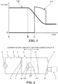
- FIG. 3 is a voltage waveform diagram in the process of the short-circuit current breaking in the first testing method.
- the DC circuit breaker 1 is connected to the testing device with the protection circuit breaker 3 and the auxiliary circuit breaker 8 in the closed state, the closing switch 4 and the starting switch 11 in the opened state, the short-circuit generator 2 in an excited state in a predetermined voltage beforehand, and the voltage source capacitor 10 charged to a predetermined voltage by the charging device 9 beforehand.
- the closing switch 4 is closed at a time A, and an AC current is supplied from the short-circuit generator 2 to the breaker unit 101 of the DC circuit breaker 1.
- This AC current is 0 A at the time A, and then increases.
- the magnitude of this AC current is adjusted by the reactor 5.
- the starting switch 11 is closed.
- This closing timing is before the AC current supplied by the short-circuit generator 2 reaches the peak value. That is, it may be up to 1/4 cycle of the AC current.
- the current supplied to the breaker unit 101 until the starting switch 11 is closed is less than the fault current due to the system accident in the DC system.
- the closing timing of the starting switch 11 may be before the breaker unit 101 of the DC circuit breaker 1 breaks the current, and includes at the same time as the current breaking or a time right before the current breaking. In this embodiment, the closing timing of the starting switch 11 is before the current breaking.
- the starting switch 11 When the starting switch 11 is closed, the AC current having a frequency determined by the voltage source capacitor 10 and the reactor 12 is supplied to the breaker unit 101. That is, when the starting switch 11 is closed, the voltage source circuit B is connected to the DC circuit breaker, and the AC current from the voltage source circuit B is superimposed on the AC current from the short-circuit generator 2. As illustrated in FIG. 2 , this superimposed current 15 is supplied to the breaker unit 101 and increases. In addition, because the starting switch 11 is closed at the time B, the voltage source circuit B is connected to the DC circuit breaker 1, and a voltage is applied to the DC circuit breaker 1. Since the main power supply of the voltage source circuit B is the voltage source capacitor 10, as illustrated in FIG. 3 , the voltage of the voltage source capacitor 10 decreases due to the discharging.
- the current 15 is current chopped by opening the breaker unit 101 and the auxiliary circuit breaker 8 at a time C which the current 15 becomes equal to or more than the fault current, and the current 15 is broken.
- the current 15 is broken when reaching the current equivalent to the fault current.
- a transient recovery voltage 17 from the voltage source circuit B is applied across the breaker unit 101 of the DC circuit breaker 1, and the surge absorber 102 absorbs the overvoltage, and as illustrated in FIG. 2 , the current supplied from the voltage source capacitor 10 becomes a surge absorber current 16 that flows through the surge absorber 102.
- the voltage of the voltage source capacitor 10 at a time C is equal to or higher than the voltage equivalent to the voltage applied to the DC circuit breaker 1 at the time of current breaking due to the accident in the DC system.
- the closing timing of the starting switch 11 is simply set to be prior to the current breaking by the DC circuit breaker 1, but like the above embodiment, if the voltage source of the voltage source circuit B is constructed by a capacitor, it is preferable that the closing timing should be set to be immediately before the current breaking by the DC circuit breaker 1. That is, in such structure, as illustrated in FIG. 3 , the voltage of the voltage source circuit B decreases by the discharge of the capacitor. Hence, when the starting switch 11 is closed at a stage quite earlier than the current breaking, there is a possibility that the predetermined recovery voltage cannot be applied at the time of current breaking.
- the closing of the starting switch 11, that is, the connection of the DC circuit breaker 1 to the voltage source circuit B is set to be immediately before the current breaking.
- the term "immediately before the current breaking" in this case means the timing at which the voltage source circuit B is capable of applying, to the DC circuit breaker 1, the predetermined recovery voltage equivalent to the voltage with the breaking of the fault current at the time of current breaking.
- FIG. 4 is a circuit diagram of a testing device that is the testing device in FIG. 1 without the reactor 12 and the capacitor 14 of the voltage source circuit B. In the second testing method, this testing device is applied. Since the voltage source circuit B does not include the reactor 12 and the capacitor 14, the voltage applied to the DC circuit breaker 1 is a DC voltage.
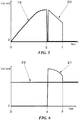
- FIG. 5 is a current waveform diagram in the process of breaking the short-circuit current according to the second testing method.
- FIG. 6 is a voltage waveform diagram in the process of breaking the short-circuit current according to the second testing method.
- the DC circuit breaker 1 is connected to the testing device, with the protection circuit breaker 3 and the auxiliary circuit breaker 8 in the closed state, the closing switch 4 and the starting switch 11 in the opened state, the short-circuit generator 2 in the excited state by the predetermined voltage beforehand, and the voltage source capacitor 10 charged to the predetermined voltage by the charging device 9 beforehand.
- the closing switch 4 is closed at a time D, and an AC current is supplied from the short-circuit generator 2 to the breaker unit 101 of the DC circuit breaker 1.
- This AC current has the magnitude adjusted by the reactor 5, and is supplied to the breaker unit 101 as a fault current 19. Note that as illustrated in FIG. 6 , even when the closing switch 4 is closed, since the voltage source circuit B is not connected to the DC circuit breaker 1, a voltage 18 of the voltage source capacitor 10 is kept constant.
- the DC circuit breaker 1 breaks a current 19. That is, at the time at which the current 19 reaches the current equivalent to the fault current due to the system accident in the DC system, the breaker block 101 is opened to current chop the current, and the current 19 is broken.
- the connection of the current source circuit B to the DC breaker 1 is maintained.
- the starting switch 11 is closed, and the auxiliary circuit breaker 8 is opened to chop the current.
- a DC voltage equivalent to the voltage source capacitor voltage 22 accumulated in the voltage source capacitor 10 is applied to the DC circuit breaker 1.
- the timing at which the voltage is applied to the DC circuit breaker 1 using the voltage source circuit B is delayed until the recovery voltage after the current breaking equivalent to the fault current is applied, the recovery voltage for the DC circuit breaker 1 can be compensated.
- the application of the DC voltage from the voltage source circuit B is set to be a timing after the current breaking and before the recovery voltage applied to the breaker unit 101 of the DC circuit breaker 1 becomes less than the voltage equivalent to the DC system fault voltage.
- This enables a verification of the withstand voltage performance of the DC circuit breaker 1 after the breaking of the fault current.
- the recovery voltage 21 keenly decreases at the timing of the time F, this is because all the energy accumulated in the reactor 5 is discharged.
- the recovery voltage can be applied to the DC circuit breaker 1 without a delay. That is, when the current breaking by the DC circuit breaker 1 is performed by a circuit breaker like a semiconductor breaker that can perform current breaking instantaneously, even if the connection of the voltage source circuit B to the DC circuit breaker 1 is attempted simultaneously with the current breaking, such connection is delayed from the time at which the current breaking is performed, and a time difference between the current breaking and the application of the recovery voltage may occur.
- the voltage source circuit B since the voltage source circuit B is connected before the current breaking and the voltage is applied, the time at which the current reaches the current equivalent to the fault current by the current breaking, and the time at which the voltage source circuit B applies the recovery voltage can be automatically matched. Hence, the recovery voltage can be applied simultaneously with the current breaking without a delay.
- the superimposed current is supplied from the voltage source circuit B, the current supplied by the current source circuit A can be reduced by what corresponds to the superimposed current.
- the voltage source circuit B is connected to the DC circuit breaker 1 simultaneously with the current breaking, it becomes unnecessary to have the short-circuit generator 2 with a large current supply for the current source circuit A. Consequently, there are advantages such that variations in use of the testing device and circuit design can be increased.
- the application of the DC voltage from the voltage source circuit B is performed while the recovery voltage is applied, no voltage is applied from the voltage source circuit B to the DC circuit breaker 1 at least until the current breaking.
- the voltage of the voltage source circuit B can be maintained, and a condition, in which the recovery voltage becomes less than the voltage equivalent to the accident voltage of the DC system after the current breaking, disrupting the verification of the withstand voltage performance after the current breaking can be avoided.
- the recovery voltage of the breaker unit 101 of the DC circuit breaker 1 after the DC breaker 1 has completed the breaking of the fault current from the current source circuit A can be compensated, and the withstand voltage performance after the current breaking can be verified.
- the above testing method for the current breaking at the instant time and testing method after the current breaking can be achieved not by a worker, but by a control unit.
- the control unit is a computer including a storage medium having stored therein a program to perform a sequence control, and may output connection or breaking instruction to the respective devices of each circuits A and B at a predetermined timing by executing the program.
- the method of verifying the current breaking performance for the DC circuit breaker by the testing device to be applied to the synthetic testing method for AC circuit breakers has been described, but a testing device equivalent to the synthetic testing method may be applied.
- the surge absorber 102 is provided in the DC circuit breaker 1, but may be provided outside the DC circuit breaker 1 as long as it is provided in parallel with the breaker unit 101.
Landscapes
- Physics & Mathematics (AREA)
- General Physics & Mathematics (AREA)
- Tests Of Circuit Breakers, Generators, And Electric Motors (AREA)
- Arc-Extinguishing Devices That Are Switches (AREA)
- Driving Mechanisms And Operating Circuits Of Arc-Extinguishing High-Tension Switches (AREA)
Abstract
Description
- Embodiments of the present disclosure relate to a testing method for verifying the current breaking performance of a DC circuit breaker.
- Large-capacity AC circuit breakers are applied to protect a system from a short-circuit accident due to lightning strike, etc., to an AC power system. A testing method called a synthetic testing method is known as a current breaking testing method for such AC circuit breakers (see, for example, Non-Patent Document 1). This synthetic testing method is performed using a testing device including a current source circuit for supplying a short-circuit current equivalent to a fault current to an AC circuit breaker subjected to a test, and a voltage source circuit that supplies a high-frequency current to apply a recovery voltage to an AC circuit breaker subjected to a test, in which both circuits are connected in parallel with each other.
- More specifically, the current breaking test of an AC circuit breaker is performed through the following procedures (1) to (4) .
- (1) An AC short-circuit current equivalent to a fault current is supplied from a current source circuit to the AC circuit breaker.
- (2) A high-frequency current is supplied from the voltage source circuit immediately before the final zero value of the short-circuit current, and a superimposed current from two circuits that are the current source circuit and the voltage source circuit is flown to the AC circuit breaker.
- (3) The current source circuit is broken from the AC circuit breaker when the short-circuit current reaches the final zero value.
- (4) Subsequently, the high-frequency current is broken by the AC circuit breaker, and a recovery voltage is generated between the terminals of the AC circuit breaker.
- Meanwhile, DC circuit breakers are applied to protect a system from the short-circuit accident of a DC system. The DC circuit breaker breaks a fault current due to short circuit, etc. In order to secure such a system protection, the DC circuit breaker needs to have a predetermined current breaking performance in accordance with the DC system.
- As the testing method for current breaking by a DC circuit breaker, there is a method of rectifying a short-circuit fault current from an AC short-circuit generator into a DC current by a rectifier, and supplying a fault current at the time of the short-circuit simulating a DC system fault.
- Non-Patent Document 1: The Institute of Electrical Engineers of Japan, Japanese Electrotechnical Committee, AC circuit breaker, JEC-2300-1998
- However, in recent years, the capacity of DC circuit breakers is increasing. Hence, in the conventional testing method using a rectifier, it is necessary to provide a large-capacity rectifier, and there are disadvantages of an increase in a size of the testing equipment and an enormous investment for installation of the testing equipment. In addition, the testing method using a large-capacity rectifier has a disadvantage in testing efficiency. Hence, it is difficult to adopt the conventional testing method using a rectifier, and other testing method is required.
- In this regard, a testing device applied for the synthetic testing method for an AC circuit breaker may be applied for the current breaking performance test of a DC circuit breaker. In this case, however, the current breaking performance test cannot be performed through the above schemes. That is, according to the above synthetic testing method, the current and the voltage equivalent to the accident of a DC system cannot be applied together to the DC circuit breaker, and the current breaking performance of the DC circuit breaker cannot be verified.
- A testing method for a DC circuit breaker according to an embodiment of the present disclosure has been made to address the foregoing disadvantages, and an objective is to provide testing a method for a DC circuit breaker verifying the current breaking performance of the DC circuit breaker.
- In order to achieve the above objective, a testing method for a DC circuit breaker according to an embodiment is a testing method for a DC circuit breaker to verify a current breaking performance using a testing device including a current source circuit and a voltage source circuit, and the method includes:
- supplying an AC current from at least the current source circuit to the DC circuit breaker;
- breaking the current by the DC circuit breaker at a time the current becomes equivalent to a fault current due to a system accident in a DC system, and
- applying a voltage to the DC circuit breaker, before the current breaking, by connecting the voltage source circuit to the DC circuit breaker, and applying a recovery voltage from the voltage source circuit simultaneously with the current breaking.
- In addition, a testing method for a DC circuit breaker according to another embodiment is a testing method of the DC circuit breaker to verify a current breaking performance using a testing device including a current source circuit and a voltage source circuit, and the method includes :
- supplying a current equivalent to a fault current due to a system accident in a DC system from the current source circuit to the DC circuit breaker;
- breaking the current by the DC circuit breaker, and applying a recovery voltage from the current source circuit to the DC circuit breaker; and
- applying a DC voltage from the voltage source circuit to the DC circuit breaker while a connection of the current source circuit to the DC circuit breaker is maintained and the recovery voltage is applied.
-
-
FIG. 1 is a circuit diagram illustrating a structure of a testing device for a DC circuit breaker according to a first embodiment; -
FIG. 2 is a current waveform diagram in the process of a short-circuit current breaking according to a first testing method; -
FIG. 3 is a voltage waveform diagram in the process of the short-circuit current breaking according to the first testing method; -
FIG. 4 is a circuit diagram illustrating a structure of a testing device for a DC circuit breaker applied in a second testing method; -
FIG. 5 is a current waveform diagram in the process of a short-circuit current breaking according to the second testing method; and -
FIG. 6 is a voltage waveform diagram in the process of the short-circuit current breaking according to the second testing method. - A testing method for a DC circuit breaker according to this embodiment, and a test device applied for the testing method will be described below with reference to
FIGs. 1 to 3 .FIG. 1 is a circuit diagram illustrating a structure of a testing device for a DC circuit breaker according to this embodiment. - The testing device for a DC circuit breaker is a device that tests the DC current breaking performance of a DC circuit breaker 1 to be tested. The testing device for the DC circuit breaker according to this embodiment employs a structure similar to that of a synthetic testing circuit applied in conventional current breaking test for an AC circuit breaker. That is, according to this embodiment, the synthetic testing circuit is used with the AC circuit breaker installed in the synthetic testing circuit replaced by a DC circuit breaker, and the current breaking performance of the DC circuit breaker is verified. More specifically, this testing device includes two power supply circuits to be described later in order to simulate the occurrence of an accident in the DC system. Example DC systems are a DC power transmission system such as a long-distance power transmission and systems between electric power companies, DC power distribution in buildings and large-scale commercial facilities, etc., and DC systems for electric railroads, etc.
- The DC circuit breaker 1 is a circuit breaker which breaks a DC current flowing in the DC circuit breaker 1. The DC circuit breaker 1 includes a
breaker unit 101 and anenergy absorbing unit 102. Thebreaker unit 101 and theenergy absorbing unit 102 are provided in parallel with each other. - The
breaker unit 101 is a switch that breaks and makes the current flowing through the circuit. Thebreaker unit 101 includes, for example, a semiconductor circuit breaker employing a semiconductor. In addition to the semiconductor breaker unit, thebreaker unit 101 may include a mechanical breaker unit that mechanically breaks and makes the current. - The
energy absorbing unit 102 is a so-called surge absorber (hereinafter, also referred to as a surge absorber 102) . The surge absorber 102 absorbs transient high-voltage energy applied to the surge absorber 102. The surge absorber 102 limits the magnitude of the voltage after the current breaking by thebreaker unit 101. - To the DC circuit breaker 1, two different power supply circuits are connected in parallel with each other. That is, the testing device according to this embodiment includes a current source circuit A that supplies an AC current to the DC circuit breaker 1, and a voltage source circuit B that applies a recovery voltage to the DC circuit breaker 1, and these circuits A and B are connected in parallel relative to the DC circuit breaker 1.
- The current source circuit A supplies an AC current to the DC circuit breaker 1. The current source circuit A includes a short-
circuit generator 2, aprotection circuit breaker 3, aclosing switch 4, areactor 5, aresistor 6, acapacitor 7, and anauxiliary circuit breaker 8. - The short-
circuit generator 2 is a generator that generates a short-circuit current. The short-circuit current generated from the short-circuit generator 2 is an AC current. The short-circuit current generated by the short-circuit generator 2 is output to the DC circuit breaker 1 via thereactor 5. - Provided between the short-
circuit generator 2 and the DC circuit breaker 1 are theprotection circuit breaker 3 and theclosing switch 4. Theclosing switch 4 is a switch for connecting the short-circuit generator 2 to the testing circuit, and switches a connection and a break of the short-circuit generator 2 relative to the DC circuit breaker 1. Theprotection circuit breaker 3 is a circuit breaker that breaks the AC short-circuit current flowing through the current source circuit A. Theprotection circuit breaker 3 breaks the AC short-circuit current at the current zero point of this current. - Further, provided in the current source circuit A are the
auxiliary circuit breaker 8 and a surge absorbing unit 41 are provided. Theauxiliary circuit breaker 8 is connected to the short-circuit generator 2, and switches a connection and a break of the DC circuit breaker 1 to be tested with the short-circuit generator 2. Theauxiliary circuit breaker 8 is, for example, a mechanical circuit breaker. In the current source circuit A, theauxiliary circuit breaker 8 is provided at the DC circuit breaker 1-side among the components. When theauxiliary circuit breaker 8 is in the closed state, the current can be supplied from the short-circuit generator 2 to the DC circuit breaker 1, and when theauxiliary circuit breaker 8 is in the opened state, the current source circuit A is disconnected from the DC circuit breaker 1, and current is not supplied from the short-circuit generator 2 to the DC circuit breaker 1. - The surge absorbing unit 41 is connected to the
auxiliary circuit breaker 8, and absorbs a surge generated when broken by theauxiliary circuit breaker 8. In the surge absorbing unit 41, theresistor 6 and thecapacitor 7 are connected in series, and thecapacitor 7 absorbs the surge via theresistor 6, facilitating theauxiliary circuit breaker 8 to break. - The voltage source circuit B applies a recovery voltage to the DC circuit breaker 1. The voltage source circuit B includes a
voltage source capacitor 10, acharging device 9, a startingswitch 11, areactor 12, aresistor 13, and acapacitor 14. - The
voltage source capacitor 10 is a DC capacitor serving as a voltage source for the voltage source circuit B. Thevoltage source capacitor 10 applies the recovery voltage to the DC circuit breaker 1 via thereactor 12 when the startingswitch 11 is in the closed state. Thevoltage source capacitor 10 has a capacity for supplying a part of the short-circuit current at the time of a DC system accident of the DC system of the DC circuit breaker 1. In addition, as for the recovery voltage, other capacitors may be applied to adjust the transient recovery voltage. - The charging
device 9 is a device connected in parallel with thevoltage source capacitor 10, and charges thevoltage source capacitor 10. The startingswitch 11 is a device for switching ON and OFF of the voltage application from thevoltage source capacitor 10. - The voltage source circuit B includes a transient oscillation circuit (an LCR circuit) with the
voltage source capacitor 10 as a DC voltage source. That is, thereactor 12, theresistor 13, and thecapacitor 14 are connected in series relative to thevoltage source capacitor 10 to construct a transient oscillation circuit. This transient oscillation circuit causes a transient phenomenon, to adjust the voltage to be applied to the DC circuit breaker 1. Hence, the recovery voltage applied by the voltage source circuit B to the DC circuit breaker 1 is a high-frequency voltage. - The
capacitor 14 is a voltage adjusting capacitor that adjusts the voltage supplied by thevoltage source capacitor 10. In this case, thecapacitor 14 is provided together with thevoltage source capacitor 10 to adjust the voltage applied to the DC circuit breaker 1 at the time of the DC system accident. - The testing method in this embodiment is a method of verifying the current breaking performance of a DC circuit breaker including a semiconductor circuit breaker for a short-circuit fault current in a DC system, and (1) a first testing method for verifying the current breaking performance at the instant time of current breaking, and (2) a second testing method for verifying the current breaking performance after the current breaking are carried out separately. The testing method for the current breaking performance at the instant time of current breaking will be described with reference to
FIGs. 2 and3 .FIG. 2 is a current waveform diagram in the process of the short-circuit current breaking in the first testing method.FIG. 3 is a voltage waveform diagram in the process of the short-circuit current breaking in the first testing method. - At the start of the test, the DC circuit breaker 1 is connected to the testing device with the
protection circuit breaker 3 and theauxiliary circuit breaker 8 in the closed state, theclosing switch 4 and the startingswitch 11 in the opened state, the short-circuit generator 2 in an excited state in a predetermined voltage beforehand, and thevoltage source capacitor 10 charged to a predetermined voltage by the chargingdevice 9 beforehand. - First, as illustrated in
FIG. 3 , theclosing switch 4 is closed at a time A, and an AC current is supplied from the short-circuit generator 2 to thebreaker unit 101 of the DC circuit breaker 1. This AC current is 0 A at the time A, and then increases. The magnitude of this AC current is adjusted by thereactor 5. - Next, at a time B, the starting
switch 11 is closed. This closing timing is before the AC current supplied by the short-circuit generator 2 reaches the peak value. That is, it may be up to 1/4 cycle of the AC current. In this embodiment, the current supplied to thebreaker unit 101 until the startingswitch 11 is closed is less than the fault current due to the system accident in the DC system. - The closing timing of the starting
switch 11 may be before thebreaker unit 101 of the DC circuit breaker 1 breaks the current, and includes at the same time as the current breaking or a time right before the current breaking. In this embodiment, the closing timing of the startingswitch 11 is before the current breaking. - When the starting
switch 11 is closed, the AC current having a frequency determined by thevoltage source capacitor 10 and thereactor 12 is supplied to thebreaker unit 101. That is, when the startingswitch 11 is closed, the voltage source circuit B is connected to the DC circuit breaker, and the AC current from the voltage source circuit B is superimposed on the AC current from the short-circuit generator 2. As illustrated inFIG. 2 , this superimposed current 15 is supplied to thebreaker unit 101 and increases. In addition, because the startingswitch 11 is closed at the time B, the voltage source circuit B is connected to the DC circuit breaker 1, and a voltage is applied to the DC circuit breaker 1. Since the main power supply of the voltage source circuit B is thevoltage source capacitor 10, as illustrated inFIG. 3 , the voltage of thevoltage source capacitor 10 decreases due to the discharging. - After the current 15 is superimposed, the current 15 is current chopped by opening the
breaker unit 101 and theauxiliary circuit breaker 8 at a time C which the current 15 becomes equal to or more than the fault current, and the current 15 is broken. In this embodiment, the current 15 is broken when reaching the current equivalent to the fault current. - Due to this current breaking, a
transient recovery voltage 17 from the voltage source circuit B is applied across thebreaker unit 101 of the DC circuit breaker 1, and thesurge absorber 102 absorbs the overvoltage, and as illustrated inFIG. 2 , the current supplied from thevoltage source capacitor 10 becomes a surge absorber current 16 that flows through thesurge absorber 102. The voltage of thevoltage source capacitor 10 at a time C is equal to or higher than the voltage equivalent to the voltage applied to the DC circuit breaker 1 at the time of current breaking due to the accident in the DC system. - As described above, at the stage of supplying the current less than the fault current to the DC circuit breaker 1, by connecting the voltage source circuit B to the DC circuit breaker 1 prior to the current breaking, both the current supply and the voltage application are performed on the DC circuit breaker 1. Hence, the current equivalent to the fault current due to the accident in the DC system, and the predetermined recovery voltage that is equivalent to the voltage to be applied with the accident are given to the DC circuit breaker 1 at the time of current breaking, and thus the current breaking performance for the DC circuit breaker 1 at the time of current breaking can be verified.
-
- (1) In the first testing method as described above, the closing timing of the starting
switch 11 is set to be a timing prior to the current breaking by the DC circuit breaker 1, and the voltage source circuit B is connected to the DC circuit breaker 1 prior to the current breaking, but it is appropriate as long as the current equivalent to the fault current and the predetermined recovery voltage equivalent to the voltage with the fault current are applied to the DC circuit breaker 1 at the time of current breaking, and the connection timing of the voltage source circuit B to the DC circuit breaker 1 may be simultaneous with this current breaking. According to this structure, also, it is possible to supply the current equivalent to the fault current and the predetermined recovery voltage equivalent to the voltage with the fault current breaking at the time of current breaking. - (2) In the first testing method as described above, the current equivalent to the fault current to the DC circuit breaker 1 is supplied by superimposing the current source circuit A and voltage source circuit B, but may be supplied by only the current source circuit A. In this case, the connection of the voltage source circuit B to the DC circuit breaker 1 is performed simultaneously with the current breaking.
- In the first testing method as described above, the closing timing of the starting
switch 11 is simply set to be prior to the current breaking by the DC circuit breaker 1, but like the above embodiment, if the voltage source of the voltage source circuit B is constructed by a capacitor, it is preferable that the closing timing should be set to be immediately before the current breaking by the DC circuit breaker 1. That is, in such structure, as illustrated inFIG. 3 , the voltage of the voltage source circuit B decreases by the discharge of the capacitor. Hence, when the startingswitch 11 is closed at a stage quite earlier than the current breaking, there is a possibility that the predetermined recovery voltage cannot be applied at the time of current breaking. Therefore, the closing of the startingswitch 11, that is, the connection of the DC circuit breaker 1 to the voltage source circuit B is set to be immediately before the current breaking. The term "immediately before the current breaking" in this case means the timing at which the voltage source circuit B is capable of applying, to the DC circuit breaker 1, the predetermined recovery voltage equivalent to the voltage with the breaking of the fault current at the time of current breaking. - Next, a second testing method, that is, a testing method for verifying the current breaking performance of the DC circuit breaker 1 after the breaking of the current equivalent to the fault current will be described.
FIG. 4 is a circuit diagram of a testing device that is the testing device inFIG. 1 without thereactor 12 and thecapacitor 14 of the voltage source circuit B. In the second testing method, this testing device is applied. Since the voltage source circuit B does not include thereactor 12 and thecapacitor 14, the voltage applied to the DC circuit breaker 1 is a DC voltage.FIG. 5 is a current waveform diagram in the process of breaking the short-circuit current according to the second testing method.FIG. 6 is a voltage waveform diagram in the process of breaking the short-circuit current according to the second testing method. - At the start of the test, the DC circuit breaker 1 is connected to the testing device, with the
protection circuit breaker 3 and theauxiliary circuit breaker 8 in the closed state, theclosing switch 4 and the startingswitch 11 in the opened state, the short-circuit generator 2 in the excited state by the predetermined voltage beforehand, and thevoltage source capacitor 10 charged to the predetermined voltage by the chargingdevice 9 beforehand. - First, as illustrated in
FIG. 5 , theclosing switch 4 is closed at a time D, and an AC current is supplied from the short-circuit generator 2 to thebreaker unit 101 of the DC circuit breaker 1. This AC current has the magnitude adjusted by thereactor 5, and is supplied to thebreaker unit 101 as a fault current 19. Note that as illustrated inFIG. 6 , even when theclosing switch 4 is closed, since the voltage source circuit B is not connected to the DC circuit breaker 1, avoltage 18 of thevoltage source capacitor 10 is kept constant. - Next, at a time E illustrated in
FIGs. 5 and 6 , the DC circuit breaker 1 breaks a current 19. That is, at the time at which the current 19 reaches the current equivalent to the fault current due to the system accident in the DC system, thebreaker block 101 is opened to current chop the current, and the current 19 is broken. - When the current 19 is broken, a
recovery voltage 21 with a frequency determined by thereactor 5, theresistor 6, and thecapacitor 7 is applied to the DC circuit breaker 1, thesurge absorber 102 absorbs the overvoltage, and as illustrated inFIG. 5 , the current supplied from the short-circuit generator 2 flows through thesurge absorber 102 as a surge absorber current 20. While the surge absorber current 20 is flowing, as illustrated inFIG. 6 , therecovery voltage 21 gradually decreases. - After the application of the
recovery voltage 21, the connection of the current source circuit B to the DC breaker 1 is maintained. After the application of thisrecovery voltage 21, at a time F at which the surge absorber current 20 is flowing, the startingswitch 11 is closed, and theauxiliary circuit breaker 8 is opened to chop the current. In this case, a DC voltage equivalent to the voltagesource capacitor voltage 22 accumulated in thevoltage source capacitor 10 is applied to the DC circuit breaker 1. - Accordingly, since the timing at which the voltage is applied to the DC circuit breaker 1 using the voltage source circuit B is delayed until the recovery voltage after the current breaking equivalent to the fault current is applied, the recovery voltage for the DC circuit breaker 1 can be compensated.
- More specifically, the application of the DC voltage from the voltage source circuit B is set to be a timing after the current breaking and before the recovery voltage applied to the
breaker unit 101 of the DC circuit breaker 1 becomes less than the voltage equivalent to the DC system fault voltage. This enables a verification of the withstand voltage performance of the DC circuit breaker 1 after the breaking of the fault current. As illustrated inFIG. 6 , in this embodiment, therecovery voltage 21 keenly decreases at the timing of the time F, this is because all the energy accumulated in thereactor 5 is discharged. -
- (1) The testing method for the DC circuit breaker according to this embodiment is a testing method for the DC circuit breaker 1 to verify the current breaking performance using the testing device including the current source circuit A and the voltage source circuit B, and the testing method includes supplying an AC current from at least the current source circuit A to the DC circuit breaker 1, breaking the current by the DC circuit breaker 1 at a time at which the current becomes equivalent to the fault current due to the system accident in the DC system, applying a voltage to the DC circuit breaker 1 by connecting the voltage source circuit B to the DC circuit breaker 1 before the current breaking, and applying the recovery voltage from the voltage source circuit B simultaneously with the current breaking.
Hence, at the time of current breaking, the current equivalent to the fault current, and the voltage equivalent to the voltage at the time of the accident can be applied to the DC circuit breaker 1, an accident in the DC system where the DC circuit breaker 1 is provided can be simulated, and the current breaking performance of the DC circuit breaker 1 can be verified. In addition, if large-power testing equipment for general AC circuit breakers is present, the current breaking test for the DC circuit breaker 1 can be performed without installing a large-capacity DC power generator and a rectifier, which are expensive and large sized. In particular, in this embodiment, since the current breaking test for the DC circuit breaker 1 is performed using the conventional testing device applied in the synthetic testing method for AC circuit breakers, it is unnecessary to additionally prepare equipment investment and equipment layout site, etc., and financial advantage is large. - (2) The current source circuit A supplies an AC current less than the current equivalent to the fault current to the DC circuit breaker 1, and the voltage source circuit B is connected to the DC circuit breaker 1 before the current breaking by the DC circuit breaker 1, the current from the voltage source circuit B is superimposed on the current of the current source circuit A to obtain the current equivalent to the fault current, and the voltage is applied to the DC circuit breaker 1.
- Hence, simultaneously with breaking of the current equivalent to the fault current, the recovery voltage can be applied to the DC circuit breaker 1 without a delay. That is, when the current breaking by the DC circuit breaker 1 is performed by a circuit breaker like a semiconductor breaker that can perform current breaking instantaneously, even if the connection of the voltage source circuit B to the DC circuit breaker 1 is attempted simultaneously with the current breaking, such connection is delayed from the time at which the current breaking is performed, and a time difference between the current breaking and the application of the recovery voltage may occur. According to this testing method, however, since the voltage source circuit B is connected before the current breaking and the voltage is applied, the time at which the current reaches the current equivalent to the fault current by the current breaking, and the time at which the voltage source circuit B applies the recovery voltage can be automatically matched. Hence, the recovery voltage can be applied simultaneously with the current breaking without a delay.
- Furthermore, since the superimposed current is supplied from the voltage source circuit B, the current supplied by the current source circuit A can be reduced by what corresponds to the superimposed current. Hence, in comparison with the case in which the voltage source circuit B is connected to the DC circuit breaker 1 simultaneously with the current breaking, it becomes unnecessary to have the short-
circuit generator 2 with a large current supply for the current source circuit A. Consequently, there are advantages such that variations in use of the testing device and circuit design can be increased. - (3) The voltage source circuit B includes the
voltage source capacitor 10 serving as the voltage source, and the connection of the voltage source circuit B to the DC circuit breaker 1 is set to be a timing at which the current is broken and immediately before the current reaches the current equivalent to the fault current. Consequently, the predetermined recovery voltage can be surely applied at the time of current breaking. That is, when the voltage source is a capacitor, the energy is discharged along with the elapsed time of the connection of the voltage source circuit B, and the voltage decreases. Hence, when the voltage source circuit B is connected to the DC circuit breaker 1 at a stage quite earlier than the current breaking, there is a possibility that the predetermined recovery voltage for verifying the current breaking performance cannot be applied at the time of current breaking. Hence, in order to avoid this disadvantage, the connection timing is set to be immediately before the current reaches the fault current, and the predetermined recovery voltage can be further surely applied at the time of current breaking. - (4) In the application of the recovery voltage from the voltage source circuit B, the overvoltage is absorbed by the
surge absorber 102 provided in parallel with the DC circuit breaker 1. Consequently, an application of the overvoltage to thebreaker unit 101 of the DC circuit breaker 1 can be suppressed, and an application of the predetermined recovery voltage can be facilitated. - (5) The current breaking testing method for the DC circuit breaker 1 in this embodiment is a testing method for a DC circuit breaker to verify the current breaking performance using the testing device including the current source circuit A and the voltage source circuit B, and includes supplying, to the DC circuit breaker 1, a current equivalent to the fault current due to the system accident in the DC system from the current source circuit A, breaking the current by the DC circuit breaker 1, applying the recovery voltage from the current source circuit A to the DC circuit breaker l,and applying the DC voltage from the voltage source circuit B to the DC circuit breaker 1 while the connection of the current source circuit A to the DC circuit breaker 1 is maintained and the recovery voltage is applied.
- Consequently, since the application of the DC voltage from the voltage source circuit B is performed while the recovery voltage is applied, no voltage is applied from the voltage source circuit B to the DC circuit breaker 1 at least until the current breaking. Hence, the voltage of the voltage source circuit B can be maintained, and a condition, in which the recovery voltage becomes less than the voltage equivalent to the accident voltage of the DC system after the current breaking, disrupting the verification of the withstand voltage performance after the current breaking can be avoided. In other words, the recovery voltage of the
breaker unit 101 of the DC circuit breaker 1 after the DC breaker 1 has completed the breaking of the fault current from the current source circuit A can be compensated, and the withstand voltage performance after the current breaking can be verified. - (5) In the application of the recovery voltage from the current source circuit A, the overvoltage is absorbed by the
surge absorber 102 provided in parallel with thebreaker unit 101 of the DC circuit breaker 1. Accordingly, an application of the overvoltage to thebreaker unit 101 of the DC circuit breaker 1 is suppressed, facilitating an application of the predetermined recovery voltage. - Several embodiments of the present disclosure have been described in this specification, but those embodiments are merely presented as examples, and are not intended to limit the scope of the present disclosure. The above embodiments can be carried out in other various forms, and various omissions, replacements, and modifications can be made thereto without departing from the scope of the present disclosure. Such embodiments and modified forms thereof are within the scope of the present disclosure, and within the scope of the invention as recited in the appended claims and equivalent range thereto.
- As for other embodiments, the above testing method for the current breaking at the instant time and testing method after the current breaking can be achieved not by a worker, but by a control unit. That is, the control unit is a computer including a storage medium having stored therein a program to perform a sequence control, and may output connection or breaking instruction to the respective devices of each circuits A and B at a predetermined timing by executing the program.
- In the first embodiment, the method of verifying the current breaking performance for the DC circuit breaker by the testing device to be applied to the synthetic testing method for AC circuit breakers has been described, but a testing device equivalent to the synthetic testing method may be applied.
- The
surge absorber 102 is provided in the DC circuit breaker 1, but may be provided outside the DC circuit breaker 1 as long as it is provided in parallel with thebreaker unit 101. -
- 1
- DC circuit breaker
- 101
- Breaker unit
- 102
- Surge absorber
- A
- Current source circuit
- 2
- Short-circuit generator
- 3
- Protection circuit breaker
- 4
- Closing switch
- 5
- Reactor
- 6
- Resistor
- 7
- Capacitor
- 8
- Auxiliary circuit breaker
- 41
- Surge absorbing unit
- B
- Voltage source circuit
- 9
- Charging device
- 10
- Voltage source capacitor
- 11
- Starting switch
- 12
- Reactor
- 13
- Resistor
- 14
- Capacitor
- 15, 19
- Current
- 16, 20
- Surge absorber current
- 17, 21
- Recovery voltage
- 18, 22
- Voltage source capacitor voltage
Claims (7)
- A testing method for a DC circuit breaker 1 to verify a current breaking performance using a testing device comprising a current source circuit and a voltage source circuit, the method comprising:supplying an AC current from at least the current source circuit to the DC circuit breaker;breaking the current by the DC circuit breaker at a time the current becomes equivalent to a fault current due to a system accident in a DC system; andapplying a voltage to the DC circuit breaker, before the current breaking, by connecting the voltage source circuit to the DC circuit breaker, and applying a recovery voltage from the voltage source circuit simultaneously with the current breaking.
- The testing method for the DC circuit breaker according to claim 1, wherein:the current source circuit supplies an AC current less than a current equivalent to the fault current to the DC circuit breaker; andthe voltage source circuit is connected to the DC circuit breaker before the current breaking by the DC circuit breaker, to superimpose a current from the voltage source circuit on the current of the current source circuit to obtain the current equivalent to the fault current, and to apply a voltage to the DC circuit breaker.
- The testing method for the DC circuit breaker according to claim 2, wherein:the voltage source circuit comprises a capacitor serving as a voltage source; andthe connection of the voltage source circuit to the DC circuit breaker is set to be a timing immediately before the current breaking.
- The testing method for the DC circuit breaker according to claim 1 or 2, wherein the testing device is a testing device applied for a synthetic testing method for AC circuit breakers.
- The testing method for DC circuit breaker according to any one of claims 1 to 4, wherein:the DC circuit breaker comprises a breaker unit breaking a current; andin the application of the recovery voltage from the voltage source circuit, an overvoltage is absorbed by a surge absorber provided in parallel with the breaker unit of the DC circuit breaker.
- A testing method for a DC circuit breaker to verify a current breaking performance using a testing device comprising a current source circuit and a voltage source circuit, the method comprising:supplying a current equivalent to a fault current due to a system accident in a DC system from the current source circuit to the DC circuit breaker;breaking the current by the DC circuit breaker, and applying a recovery voltage from the current source circuit to the DC circuit breaker; andapplying a DC voltage from the voltage source circuit to the DC circuit breaker while a connection of the current source circuit to the DC circuit breaker is maintained and the recovery voltage is applied.
- The testing method for the DC circuit breaker according to claim 6, wherein:the DC circuit breaker comprises a breaker unit breaking a current; andin the application of the recovery voltage from the current source circuit, an overvoltage is absorbed by a surge absorber provided in parallel with the breaker unit of the DC circuit breaker.
Applications Claiming Priority (2)
| Application Number | Priority Date | Filing Date | Title |
|---|---|---|---|
| JP2015128419A JP6645758B2 (en) | 2015-06-26 | 2015-06-26 | DC breaker test method |
| PCT/JP2016/067736 WO2016208465A1 (en) | 2015-06-26 | 2016-06-15 | Testing method for dc circuit breaker |
Publications (3)
| Publication Number | Publication Date |
|---|---|
| EP3315980A1 true EP3315980A1 (en) | 2018-05-02 |
| EP3315980A4 EP3315980A4 (en) | 2019-02-20 |
| EP3315980B1 EP3315980B1 (en) | 2024-05-15 |
Family
ID=57585437
Family Applications (1)
| Application Number | Title | Priority Date | Filing Date |
|---|---|---|---|
| EP16814236.2A Active EP3315980B1 (en) | 2015-06-26 | 2016-06-15 | Testing method for a dc circuit breaker |
Country Status (4)
| Country | Link |
|---|---|
| EP (1) | EP3315980B1 (en) |
| JP (1) | JP6645758B2 (en) |
| CN (1) | CN107110912B (en) |
| WO (1) | WO2016208465A1 (en) |
Cited By (1)
| Publication number | Priority date | Publication date | Assignee | Title |
|---|---|---|---|---|
| CN113567850A (en) * | 2021-07-27 | 2021-10-29 | 西安交通大学 | System and method for verifying on-off performance of medium-low voltage direct current distribution switchgear |
Families Citing this family (9)
| Publication number | Priority date | Publication date | Assignee | Title |
|---|---|---|---|---|
| WO2018146748A1 (en) * | 2017-02-08 | 2018-08-16 | 三菱電機株式会社 | Testing device and testing method for dc circuit breaker |
| CN107526030A (en) * | 2017-07-05 | 2017-12-29 | 全球能源互联网研究院 | The synthetic test equipment and method of a kind of high voltage DC breaker |
| CN109188121B (en) * | 2018-08-14 | 2020-09-08 | 西北工业大学 | Fault detection method for rotating rectifier in static state of three-stage starting/generator |
| CN110161405B (en) * | 2019-07-01 | 2020-08-04 | 大连理工大学 | A three-power DC breaker synthesis test circuit and its test method |
| CN112630640B (en) * | 2020-12-09 | 2022-02-22 | 西安交通大学 | DC circuit breaker synthesis test loop and method of two-level voltage source |
| CN113625160A (en) * | 2021-08-06 | 2021-11-09 | 甘肃电器科学研究院 | Synchronous control system for 126KV high-voltage alternating-current circuit breaker synthesis test |
| CN115980558A (en) * | 2021-10-14 | 2023-04-18 | 西安高压电器研究院股份有限公司 | A Synthetic Test Loop |
| CN113777437B (en) * | 2021-11-15 | 2022-02-11 | 中国电力科学研究院有限公司 | A system and method for testing UHV DC wall bushings |
| CN114325377A (en) * | 2022-01-04 | 2022-04-12 | 中车株洲电力机车有限公司 | System and method for fault diagnosis and prediction of vacuum main circuit breaker, locomotive |
Family Cites Families (9)
| Publication number | Priority date | Publication date | Assignee | Title |
|---|---|---|---|---|
| DE2336713A1 (en) * | 1973-07-19 | 1975-02-06 | Dieter Prof Dr Ing Kind | ARRANGEMENT FOR SYNTHETIC TESTING OF HIGH VOLTAGE DC SWITCHES |
| JPS5280476A (en) * | 1975-12-26 | 1977-07-06 | Tokyo Shibaura Electric Co | Dc breaker equivalent tester |
| JPS5757267A (en) * | 1980-09-24 | 1982-04-06 | Hitachi Ltd | Combined equivalent testing apparatus for dc breaker |
| EP0242707A1 (en) * | 1986-04-22 | 1987-10-28 | BBC Brown Boveri AG | Test circuit |
| JP2003115242A (en) * | 2001-10-03 | 2003-04-18 | Toshiba Corp | Circuit breaker test circuit |
| JP2015056389A (en) * | 2013-09-13 | 2015-03-23 | 株式会社東芝 | Tester of dc circuit breaker and method of testing thereof |
| JP2015059891A (en) * | 2013-09-20 | 2015-03-30 | 株式会社東芝 | DC circuit breaker test apparatus and test method using DC circuit breaker test apparatus |
| CN104535923B (en) * | 2014-12-27 | 2017-10-31 | 中国西电电气股份有限公司 | A kind of test loop detected for dc circuit breaker break performance and test method |
| CN106646206B (en) * | 2015-10-29 | 2019-11-08 | 全球能源互联网研究院 | High-voltage and high-current composite injection DC circuit breaker synthetic test circuit and method |
-
2015
- 2015-06-26 JP JP2015128419A patent/JP6645758B2/en active Active
-
2016
- 2016-06-15 CN CN201680004929.9A patent/CN107110912B/en active Active
- 2016-06-15 EP EP16814236.2A patent/EP3315980B1/en active Active
- 2016-06-15 WO PCT/JP2016/067736 patent/WO2016208465A1/en not_active Ceased
Cited By (1)
| Publication number | Priority date | Publication date | Assignee | Title |
|---|---|---|---|---|
| CN113567850A (en) * | 2021-07-27 | 2021-10-29 | 西安交通大学 | System and method for verifying on-off performance of medium-low voltage direct current distribution switchgear |
Also Published As
| Publication number | Publication date |
|---|---|
| CN107110912A (en) | 2017-08-29 |
| JP6645758B2 (en) | 2020-02-14 |
| CN107110912B (en) | 2019-08-27 |
| EP3315980A4 (en) | 2019-02-20 |
| JP2017009552A (en) | 2017-01-12 |
| WO2016208465A1 (en) | 2016-12-29 |
| EP3315980B1 (en) | 2024-05-15 |
Similar Documents
| Publication | Publication Date | Title |
|---|---|---|
| EP3315980B1 (en) | Testing method for a dc circuit breaker | |
| EP3557268B1 (en) | Testing apparatus for dc circuit breaker | |
| McDermit et al. | Medium voltage switching transient induced potential transformer failures; prediction, measurement and practical solutions | |
| Belda et al. | Full-power test of HVDC circuit-breakers with AC short-circuit generators operated at low power frequency | |
| CN101958530A (en) | Main transformer differential protection CT polarity check method of pumped storage power station | |
| CN109031106B (en) | Hybrid direct current breaker breaking test device | |
| JP2015059891A (en) | DC circuit breaker test apparatus and test method using DC circuit breaker test apparatus | |
| WO2015037223A1 (en) | Device for testing dc circuit breaker and testing method therefor | |
| Meddeb et al. | Impact of distributed generation on the protection system in Tunisian distribution network | |
| NL2006296C2 (en) | Device to protect an electric power distribution network against current faults. | |
| JP5677148B2 (en) | Capacitor bank switching performance test equipment | |
| CN109655744B (en) | Direct current breaker test voltage generation circuit and generation method | |
| Kuchanskyy | Measures and technical means for increasing efficiency and reliability of extra high voltage transmission lines | |
| CN108196177A (en) | A kind of semiconductor subassembly Performance Test System | |
| JP2016213123A (en) | DC circuit breaker test apparatus and test method thereof | |
| CN102213740A (en) | Middle-high voltage electric power circuit fault detection method and system of unilateral power supply under power failure state | |
| Auran et al. | A novel pole-to-ground fault detection algorithm for meshed HVDC grids with half-bridge MMC converters and full recourse to DC circuit breakers | |
| Belda et al. | Performance demonstration of HVDC circuit breakers | |
| Bui-Van et al. | Performance of series-compensated line circuit breakers under delayed current-zero conditions | |
| Berger et al. | Proposal of a time-domain platform for short-circuit protection analysis in rapid transit train DC auxiliary systems | |
| JPH0735831A (en) | Circuit breaker test method and device | |
| Chen et al. | The power plant arrester configuration and modeling of insulation coordination | |
| Usman et al. | Development of a 500V/0.3 kA DC Circuit Breaker Testbed Using a DC Chopper Energized Capacitor Bank | |
| Li et al. | Short-Circuit Analysis of Solid-State Transformer-Based DC Distribution in Data Center | |
| CN120033812A (en) | Bus overvoltage system and calculation method for AC filter bus charging and small filter operation |
Legal Events
| Date | Code | Title | Description |
|---|---|---|---|
| STAA | Information on the status of an ep patent application or granted ep patent |
Free format text: STATUS: THE INTERNATIONAL PUBLICATION HAS BEEN MADE |
|
| PUAI | Public reference made under article 153(3) epc to a published international application that has entered the european phase |
Free format text: ORIGINAL CODE: 0009012 |
|
| STAA | Information on the status of an ep patent application or granted ep patent |
Free format text: STATUS: REQUEST FOR EXAMINATION WAS MADE |
|
| 17P | Request for examination filed |
Effective date: 20171219 |
|
| AK | Designated contracting states |
Kind code of ref document: A1 Designated state(s): AL AT BE BG CH CY CZ DE DK EE ES FI FR GB GR HR HU IE IS IT LI LT LU LV MC MK MT NL NO PL PT RO RS SE SI SK SM TR |
|
| AX | Request for extension of the european patent |
Extension state: BA ME |
|
| DAV | Request for validation of the european patent (deleted) | ||
| DAX | Request for extension of the european patent (deleted) | ||
| A4 | Supplementary search report drawn up and despatched |
Effective date: 20190121 |
|
| RIC1 | Information provided on ipc code assigned before grant |
Ipc: G01R 31/333 20060101AFI20190115BHEP Ipc: G01R 31/327 20060101ALI20190115BHEP |
|
| STAA | Information on the status of an ep patent application or granted ep patent |
Free format text: STATUS: EXAMINATION IS IN PROGRESS |
|
| 17Q | First examination report despatched |
Effective date: 20220503 |
|
| GRAP | Despatch of communication of intention to grant a patent |
Free format text: ORIGINAL CODE: EPIDOSNIGR1 |
|
| STAA | Information on the status of an ep patent application or granted ep patent |
Free format text: STATUS: GRANT OF PATENT IS INTENDED |
|
| INTG | Intention to grant announced |
Effective date: 20240214 |
|
| GRAS | Grant fee paid |
Free format text: ORIGINAL CODE: EPIDOSNIGR3 |
|
| GRAA | (expected) grant |
Free format text: ORIGINAL CODE: 0009210 |
|
| STAA | Information on the status of an ep patent application or granted ep patent |
Free format text: STATUS: THE PATENT HAS BEEN GRANTED |
|
| RAP3 | Party data changed (applicant data changed or rights of an application transferred) |
Owner name: KABUSHIKI KAISHA TOSHIBA |
|
| AK | Designated contracting states |
Kind code of ref document: B1 Designated state(s): AL AT BE BG CH CY CZ DE DK EE ES FI FR GB GR HR HU IE IS IT LI LT LU LV MC MK MT NL NO PL PT RO RS SE SI SK SM TR |
|
| REG | Reference to a national code |
Ref country code: CH Ref legal event code: EP Ref country code: GB Ref legal event code: FG4D |
|
| REG | Reference to a national code |
Ref country code: DE Ref legal event code: R096 Ref document number: 602016087547 Country of ref document: DE |
|
| REG | Reference to a national code |
Ref country code: IE Ref legal event code: FG4D |
|
| PGFP | Annual fee paid to national office [announced via postgrant information from national office to epo] |
Ref country code: NL Payment date: 20240527 Year of fee payment: 9 |
|
| PGFP | Annual fee paid to national office [announced via postgrant information from national office to epo] |
Ref country code: GB Payment date: 20240524 Year of fee payment: 9 |
|
| PGFP | Annual fee paid to national office [announced via postgrant information from national office to epo] |
Ref country code: DE Payment date: 20240522 Year of fee payment: 9 |
|
| REG | Reference to a national code |
Ref country code: LT Ref legal event code: MG9D |
|
| REG | Reference to a national code |
Ref country code: NL Ref legal event code: MP Effective date: 20240515 |
|
| PG25 | Lapsed in a contracting state [announced via postgrant information from national office to epo] |
Ref country code: IS Free format text: LAPSE BECAUSE OF FAILURE TO SUBMIT A TRANSLATION OF THE DESCRIPTION OR TO PAY THE FEE WITHIN THE PRESCRIBED TIME-LIMIT Effective date: 20240915 |
|
| PG25 | Lapsed in a contracting state [announced via postgrant information from national office to epo] |
Ref country code: BG Free format text: LAPSE BECAUSE OF FAILURE TO SUBMIT A TRANSLATION OF THE DESCRIPTION OR TO PAY THE FEE WITHIN THE PRESCRIBED TIME-LIMIT Effective date: 20240515 |
|
| PG25 | Lapsed in a contracting state [announced via postgrant information from national office to epo] |
Ref country code: HR Free format text: LAPSE BECAUSE OF FAILURE TO SUBMIT A TRANSLATION OF THE DESCRIPTION OR TO PAY THE FEE WITHIN THE PRESCRIBED TIME-LIMIT Effective date: 20240515 Ref country code: FI Free format text: LAPSE BECAUSE OF FAILURE TO SUBMIT A TRANSLATION OF THE DESCRIPTION OR TO PAY THE FEE WITHIN THE PRESCRIBED TIME-LIMIT Effective date: 20240515 |
|
| PG25 | Lapsed in a contracting state [announced via postgrant information from national office to epo] |
Ref country code: GR Free format text: LAPSE BECAUSE OF FAILURE TO SUBMIT A TRANSLATION OF THE DESCRIPTION OR TO PAY THE FEE WITHIN THE PRESCRIBED TIME-LIMIT Effective date: 20240816 |
|
| PG25 | Lapsed in a contracting state [announced via postgrant information from national office to epo] |
Ref country code: PT Free format text: LAPSE BECAUSE OF FAILURE TO SUBMIT A TRANSLATION OF THE DESCRIPTION OR TO PAY THE FEE WITHIN THE PRESCRIBED TIME-LIMIT Effective date: 20240916 |
|
| REG | Reference to a national code |
Ref country code: AT Ref legal event code: MK05 Ref document number: 1687320 Country of ref document: AT Kind code of ref document: T Effective date: 20240515 |
|
| PG25 | Lapsed in a contracting state [announced via postgrant information from national office to epo] |
Ref country code: NL Free format text: LAPSE BECAUSE OF FAILURE TO SUBMIT A TRANSLATION OF THE DESCRIPTION OR TO PAY THE FEE WITHIN THE PRESCRIBED TIME-LIMIT Effective date: 20240515 |
|
| PG25 | Lapsed in a contracting state [announced via postgrant information from national office to epo] |
Ref country code: ES Free format text: LAPSE BECAUSE OF FAILURE TO SUBMIT A TRANSLATION OF THE DESCRIPTION OR TO PAY THE FEE WITHIN THE PRESCRIBED TIME-LIMIT Effective date: 20240515 |
|
| PGFP | Annual fee paid to national office [announced via postgrant information from national office to epo] |
Ref country code: CH Payment date: 20240701 Year of fee payment: 9 |
|
| PG25 | Lapsed in a contracting state [announced via postgrant information from national office to epo] |
Ref country code: AT Free format text: LAPSE BECAUSE OF FAILURE TO SUBMIT A TRANSLATION OF THE DESCRIPTION OR TO PAY THE FEE WITHIN THE PRESCRIBED TIME-LIMIT Effective date: 20240515 |
|
| PG25 | Lapsed in a contracting state [announced via postgrant information from national office to epo] |
Ref country code: PL Free format text: LAPSE BECAUSE OF FAILURE TO SUBMIT A TRANSLATION OF THE DESCRIPTION OR TO PAY THE FEE WITHIN THE PRESCRIBED TIME-LIMIT Effective date: 20240515 |
|
| PG25 | Lapsed in a contracting state [announced via postgrant information from national office to epo] |
Ref country code: LV Free format text: LAPSE BECAUSE OF FAILURE TO SUBMIT A TRANSLATION OF THE DESCRIPTION OR TO PAY THE FEE WITHIN THE PRESCRIBED TIME-LIMIT Effective date: 20240515 |
|
| PG25 | Lapsed in a contracting state [announced via postgrant information from national office to epo] |
Ref country code: PT Free format text: LAPSE BECAUSE OF FAILURE TO SUBMIT A TRANSLATION OF THE DESCRIPTION OR TO PAY THE FEE WITHIN THE PRESCRIBED TIME-LIMIT Effective date: 20240916 Ref country code: PL Free format text: LAPSE BECAUSE OF FAILURE TO SUBMIT A TRANSLATION OF THE DESCRIPTION OR TO PAY THE FEE WITHIN THE PRESCRIBED TIME-LIMIT Effective date: 20240515 Ref country code: NO Free format text: LAPSE BECAUSE OF FAILURE TO SUBMIT A TRANSLATION OF THE DESCRIPTION OR TO PAY THE FEE WITHIN THE PRESCRIBED TIME-LIMIT Effective date: 20240815 Ref country code: NL Free format text: LAPSE BECAUSE OF FAILURE TO SUBMIT A TRANSLATION OF THE DESCRIPTION OR TO PAY THE FEE WITHIN THE PRESCRIBED TIME-LIMIT Effective date: 20240515 Ref country code: LV Free format text: LAPSE BECAUSE OF FAILURE TO SUBMIT A TRANSLATION OF THE DESCRIPTION OR TO PAY THE FEE WITHIN THE PRESCRIBED TIME-LIMIT Effective date: 20240515 Ref country code: IS Free format text: LAPSE BECAUSE OF FAILURE TO SUBMIT A TRANSLATION OF THE DESCRIPTION OR TO PAY THE FEE WITHIN THE PRESCRIBED TIME-LIMIT Effective date: 20240915 Ref country code: HR Free format text: LAPSE BECAUSE OF FAILURE TO SUBMIT A TRANSLATION OF THE DESCRIPTION OR TO PAY THE FEE WITHIN THE PRESCRIBED TIME-LIMIT Effective date: 20240515 Ref country code: GR Free format text: LAPSE BECAUSE OF FAILURE TO SUBMIT A TRANSLATION OF THE DESCRIPTION OR TO PAY THE FEE WITHIN THE PRESCRIBED TIME-LIMIT Effective date: 20240816 Ref country code: FI Free format text: LAPSE BECAUSE OF FAILURE TO SUBMIT A TRANSLATION OF THE DESCRIPTION OR TO PAY THE FEE WITHIN THE PRESCRIBED TIME-LIMIT Effective date: 20240515 Ref country code: ES Free format text: LAPSE BECAUSE OF FAILURE TO SUBMIT A TRANSLATION OF THE DESCRIPTION OR TO PAY THE FEE WITHIN THE PRESCRIBED TIME-LIMIT Effective date: 20240515 Ref country code: BG Free format text: LAPSE BECAUSE OF FAILURE TO SUBMIT A TRANSLATION OF THE DESCRIPTION OR TO PAY THE FEE WITHIN THE PRESCRIBED TIME-LIMIT Effective date: 20240515 Ref country code: AT Free format text: LAPSE BECAUSE OF FAILURE TO SUBMIT A TRANSLATION OF THE DESCRIPTION OR TO PAY THE FEE WITHIN THE PRESCRIBED TIME-LIMIT Effective date: 20240515 Ref country code: RS Free format text: LAPSE BECAUSE OF FAILURE TO SUBMIT A TRANSLATION OF THE DESCRIPTION OR TO PAY THE FEE WITHIN THE PRESCRIBED TIME-LIMIT Effective date: 20240815 |
|
| PG25 | Lapsed in a contracting state [announced via postgrant information from national office to epo] |
Ref country code: DK Free format text: LAPSE BECAUSE OF FAILURE TO SUBMIT A TRANSLATION OF THE DESCRIPTION OR TO PAY THE FEE WITHIN THE PRESCRIBED TIME-LIMIT Effective date: 20240515 |
|
| PG25 | Lapsed in a contracting state [announced via postgrant information from national office to epo] |
Ref country code: EE Free format text: LAPSE BECAUSE OF FAILURE TO SUBMIT A TRANSLATION OF THE DESCRIPTION OR TO PAY THE FEE WITHIN THE PRESCRIBED TIME-LIMIT Effective date: 20240515 |
|
| PG25 | Lapsed in a contracting state [announced via postgrant information from national office to epo] |
Ref country code: CZ Free format text: LAPSE BECAUSE OF FAILURE TO SUBMIT A TRANSLATION OF THE DESCRIPTION OR TO PAY THE FEE WITHIN THE PRESCRIBED TIME-LIMIT Effective date: 20240515 |
|
| PG25 | Lapsed in a contracting state [announced via postgrant information from national office to epo] |
Ref country code: SK Free format text: LAPSE BECAUSE OF FAILURE TO SUBMIT A TRANSLATION OF THE DESCRIPTION OR TO PAY THE FEE WITHIN THE PRESCRIBED TIME-LIMIT Effective date: 20240515 Ref country code: RO Free format text: LAPSE BECAUSE OF FAILURE TO SUBMIT A TRANSLATION OF THE DESCRIPTION OR TO PAY THE FEE WITHIN THE PRESCRIBED TIME-LIMIT Effective date: 20240515 |
|
| PG25 | Lapsed in a contracting state [announced via postgrant information from national office to epo] |
Ref country code: SM Free format text: LAPSE BECAUSE OF FAILURE TO SUBMIT A TRANSLATION OF THE DESCRIPTION OR TO PAY THE FEE WITHIN THE PRESCRIBED TIME-LIMIT Effective date: 20240515 |
|
| PG25 | Lapsed in a contracting state [announced via postgrant information from national office to epo] |
Ref country code: SM Free format text: LAPSE BECAUSE OF FAILURE TO SUBMIT A TRANSLATION OF THE DESCRIPTION OR TO PAY THE FEE WITHIN THE PRESCRIBED TIME-LIMIT Effective date: 20240515 Ref country code: SK Free format text: LAPSE BECAUSE OF FAILURE TO SUBMIT A TRANSLATION OF THE DESCRIPTION OR TO PAY THE FEE WITHIN THE PRESCRIBED TIME-LIMIT Effective date: 20240515 Ref country code: RO Free format text: LAPSE BECAUSE OF FAILURE TO SUBMIT A TRANSLATION OF THE DESCRIPTION OR TO PAY THE FEE WITHIN THE PRESCRIBED TIME-LIMIT Effective date: 20240515 Ref country code: EE Free format text: LAPSE BECAUSE OF FAILURE TO SUBMIT A TRANSLATION OF THE DESCRIPTION OR TO PAY THE FEE WITHIN THE PRESCRIBED TIME-LIMIT Effective date: 20240515 Ref country code: DK Free format text: LAPSE BECAUSE OF FAILURE TO SUBMIT A TRANSLATION OF THE DESCRIPTION OR TO PAY THE FEE WITHIN THE PRESCRIBED TIME-LIMIT Effective date: 20240515 Ref country code: CZ Free format text: LAPSE BECAUSE OF FAILURE TO SUBMIT A TRANSLATION OF THE DESCRIPTION OR TO PAY THE FEE WITHIN THE PRESCRIBED TIME-LIMIT Effective date: 20240515 |
|
| PG25 | Lapsed in a contracting state [announced via postgrant information from national office to epo] |
Ref country code: IT Free format text: LAPSE BECAUSE OF FAILURE TO SUBMIT A TRANSLATION OF THE DESCRIPTION OR TO PAY THE FEE WITHIN THE PRESCRIBED TIME-LIMIT Effective date: 20240515 Ref country code: MC Free format text: LAPSE BECAUSE OF FAILURE TO SUBMIT A TRANSLATION OF THE DESCRIPTION OR TO PAY THE FEE WITHIN THE PRESCRIBED TIME-LIMIT Effective date: 20240515 |
|
| PG25 | Lapsed in a contracting state [announced via postgrant information from national office to epo] |
Ref country code: LU Free format text: LAPSE BECAUSE OF NON-PAYMENT OF DUE FEES Effective date: 20240615 |
|
| REG | Reference to a national code |
Ref country code: DE Ref legal event code: R097 Ref document number: 602016087547 Country of ref document: DE |
|
| PLBE | No opposition filed within time limit |
Free format text: ORIGINAL CODE: 0009261 |
|
| STAA | Information on the status of an ep patent application or granted ep patent |
Free format text: STATUS: NO OPPOSITION FILED WITHIN TIME LIMIT |
|
| PG25 | Lapsed in a contracting state [announced via postgrant information from national office to epo] |
Ref country code: IE Free format text: LAPSE BECAUSE OF NON-PAYMENT OF DUE FEES Effective date: 20240615 |
|
| 26N | No opposition filed |
Effective date: 20250218 |
|
| PG25 | Lapsed in a contracting state [announced via postgrant information from national office to epo] |
Ref country code: SI Free format text: LAPSE BECAUSE OF FAILURE TO SUBMIT A TRANSLATION OF THE DESCRIPTION OR TO PAY THE FEE WITHIN THE PRESCRIBED TIME-LIMIT Effective date: 20240515 Ref country code: BE Free format text: LAPSE BECAUSE OF NON-PAYMENT OF DUE FEES Effective date: 20240630 |
|
| PG25 | Lapsed in a contracting state [announced via postgrant information from national office to epo] |
Ref country code: FR Free format text: LAPSE BECAUSE OF NON-PAYMENT OF DUE FEES Effective date: 20240715 |
|
| REG | Reference to a national code |
Ref country code: BE Ref legal event code: MM Effective date: 20240630 |
|
| PG25 | Lapsed in a contracting state [announced via postgrant information from national office to epo] |
Ref country code: SE Free format text: LAPSE BECAUSE OF FAILURE TO SUBMIT A TRANSLATION OF THE DESCRIPTION OR TO PAY THE FEE WITHIN THE PRESCRIBED TIME-LIMIT Effective date: 20240515 |
|
| PG25 | Lapsed in a contracting state [announced via postgrant information from national office to epo] |
Ref country code: CY Free format text: LAPSE BECAUSE OF FAILURE TO SUBMIT A TRANSLATION OF THE DESCRIPTION OR TO PAY THE FEE WITHIN THE PRESCRIBED TIME-LIMIT; INVALID AB INITIO Effective date: 20160615 |
|
| REG | Reference to a national code |
Ref country code: DE Ref legal event code: R119 Ref document number: 602016087547 Country of ref document: DE |
|
| PGFP | Annual fee paid to national office [announced via postgrant information from national office to epo] |
Ref country code: SE Payment date: 20240913 Year of fee payment: 9 |
|
| REG | Reference to a national code |
Ref country code: CH Ref legal event code: H13 Free format text: ST27 STATUS EVENT CODE: U-0-0-H10-H13 (AS PROVIDED BY THE NATIONAL OFFICE) Effective date: 20260127 |
|
| GBPC | Gb: european patent ceased through non-payment of renewal fee |
Effective date: 20250615 |
|
| PG25 | Lapsed in a contracting state [announced via postgrant information from national office to epo] |
Ref country code: HU Free format text: LAPSE BECAUSE OF FAILURE TO SUBMIT A TRANSLATION OF THE DESCRIPTION OR TO PAY THE FEE WITHIN THE PRESCRIBED TIME-LIMIT; INVALID AB INITIO Effective date: 20160615 |
|
| PG25 | Lapsed in a contracting state [announced via postgrant information from national office to epo] |
Ref country code: GB Free format text: LAPSE BECAUSE OF NON-PAYMENT OF DUE FEES Effective date: 20250615 |
|
| PG25 | Lapsed in a contracting state [announced via postgrant information from national office to epo] |
Ref country code: DE Free format text: LAPSE BECAUSE OF NON-PAYMENT OF DUE FEES Effective date: 20260101 |
|
| PG25 | Lapsed in a contracting state [announced via postgrant information from national office to epo] |
Ref country code: CH Free format text: LAPSE BECAUSE OF NON-PAYMENT OF DUE FEES Effective date: 20250630 |