EP3315890A1 - Joint d'étanchéité pour échangeur de chaleur d'automobile - Google Patents
Joint d'étanchéité pour échangeur de chaleur d'automobile Download PDFInfo
- Publication number
- EP3315890A1 EP3315890A1 EP16461565.0A EP16461565A EP3315890A1 EP 3315890 A1 EP3315890 A1 EP 3315890A1 EP 16461565 A EP16461565 A EP 16461565A EP 3315890 A1 EP3315890 A1 EP 3315890A1
- Authority
- EP
- European Patent Office
- Prior art keywords
- sideplate
- air seal
- longitudinal
- heat exchanger
- lock
- Prior art date
- Legal status (The legal status is an assumption and is not a legal conclusion. Google has not performed a legal analysis and makes no representation as to the accuracy of the status listed.)
- Granted
Links
- 230000000903 blocking effect Effects 0.000 claims abstract description 19
- 238000000034 method Methods 0.000 claims description 4
- 238000001125 extrusion Methods 0.000 claims description 3
- 230000001846 repelling effect Effects 0.000 claims description 3
- 239000012634 fragment Substances 0.000 description 3
- 238000007789 sealing Methods 0.000 description 2
- 230000001419 dependent effect Effects 0.000 description 1
Images
Classifications
-
- F—MECHANICAL ENGINEERING; LIGHTING; HEATING; WEAPONS; BLASTING
- F28—HEAT EXCHANGE IN GENERAL
- F28D—HEAT-EXCHANGE APPARATUS, NOT PROVIDED FOR IN ANOTHER SUBCLASS, IN WHICH THE HEAT-EXCHANGE MEDIA DO NOT COME INTO DIRECT CONTACT
- F28D1/00—Heat-exchange apparatus having stationary conduit assemblies for one heat-exchange medium only, the media being in contact with different sides of the conduit wall, in which the other heat-exchange medium is a large body of fluid, e.g. domestic or motor car radiators
- F28D1/02—Heat-exchange apparatus having stationary conduit assemblies for one heat-exchange medium only, the media being in contact with different sides of the conduit wall, in which the other heat-exchange medium is a large body of fluid, e.g. domestic or motor car radiators with heat-exchange conduits immersed in the body of fluid
- F28D1/04—Heat-exchange apparatus having stationary conduit assemblies for one heat-exchange medium only, the media being in contact with different sides of the conduit wall, in which the other heat-exchange medium is a large body of fluid, e.g. domestic or motor car radiators with heat-exchange conduits immersed in the body of fluid with tubular conduits
- F28D1/053—Heat-exchange apparatus having stationary conduit assemblies for one heat-exchange medium only, the media being in contact with different sides of the conduit wall, in which the other heat-exchange medium is a large body of fluid, e.g. domestic or motor car radiators with heat-exchange conduits immersed in the body of fluid with tubular conduits the conduits being straight
- F28D1/0535—Heat-exchange apparatus having stationary conduit assemblies for one heat-exchange medium only, the media being in contact with different sides of the conduit wall, in which the other heat-exchange medium is a large body of fluid, e.g. domestic or motor car radiators with heat-exchange conduits immersed in the body of fluid with tubular conduits the conduits being straight the conduits having a non-circular cross-section
- F28D1/05366—Assemblies of conduits connected to common headers, e.g. core type radiators
-
- B—PERFORMING OPERATIONS; TRANSPORTING
- B60—VEHICLES IN GENERAL
- B60H—ARRANGEMENTS OF HEATING, COOLING, VENTILATING OR OTHER AIR-TREATING DEVICES SPECIALLY ADAPTED FOR PASSENGER OR GOODS SPACES OF VEHICLES
- B60H1/00—Heating, cooling or ventilating [HVAC] devices
- B60H1/00507—Details, e.g. mounting arrangements, desaeration devices
- B60H1/00514—Details of air conditioning housings
- B60H1/00521—Mounting or fastening of components in housings, e.g. heat exchangers, fans, electronic regulators
-
- B—PERFORMING OPERATIONS; TRANSPORTING
- B60—VEHICLES IN GENERAL
- B60K—ARRANGEMENT OR MOUNTING OF PROPULSION UNITS OR OF TRANSMISSIONS IN VEHICLES; ARRANGEMENT OR MOUNTING OF PLURAL DIVERSE PRIME-MOVERS IN VEHICLES; AUXILIARY DRIVES FOR VEHICLES; INSTRUMENTATION OR DASHBOARDS FOR VEHICLES; ARRANGEMENTS IN CONNECTION WITH COOLING, AIR INTAKE, GAS EXHAUST OR FUEL SUPPLY OF PROPULSION UNITS IN VEHICLES
- B60K11/00—Arrangement in connection with cooling of propulsion units
- B60K11/02—Arrangement in connection with cooling of propulsion units with liquid cooling
- B60K11/04—Arrangement or mounting of radiators, radiator shutters, or radiator blinds
-
- F—MECHANICAL ENGINEERING; LIGHTING; HEATING; WEAPONS; BLASTING
- F01—MACHINES OR ENGINES IN GENERAL; ENGINE PLANTS IN GENERAL; STEAM ENGINES
- F01P—COOLING OF MACHINES OR ENGINES IN GENERAL; COOLING OF INTERNAL-COMBUSTION ENGINES
- F01P11/00—Component parts, details, or accessories not provided for in, or of interest apart from, groups F01P1/00 - F01P9/00
- F01P11/10—Guiding or ducting cooling-air, to, or from, liquid-to-air heat exchangers
-
- F—MECHANICAL ENGINEERING; LIGHTING; HEATING; WEAPONS; BLASTING
- F01—MACHINES OR ENGINES IN GENERAL; ENGINE PLANTS IN GENERAL; STEAM ENGINES
- F01P—COOLING OF MACHINES OR ENGINES IN GENERAL; COOLING OF INTERNAL-COMBUSTION ENGINES
- F01P3/00—Liquid cooling
- F01P3/18—Arrangements or mounting of liquid-to-air heat-exchangers
-
- B—PERFORMING OPERATIONS; TRANSPORTING
- B60—VEHICLES IN GENERAL
- B60H—ARRANGEMENTS OF HEATING, COOLING, VENTILATING OR OTHER AIR-TREATING DEVICES SPECIALLY ADAPTED FOR PASSENGER OR GOODS SPACES OF VEHICLES
- B60H1/00—Heating, cooling or ventilating [HVAC] devices
- B60H1/00507—Details, e.g. mounting arrangements, desaeration devices
- B60H2001/00635—Air-tight sealing devices
-
- F—MECHANICAL ENGINEERING; LIGHTING; HEATING; WEAPONS; BLASTING
- F28—HEAT EXCHANGE IN GENERAL
- F28F—DETAILS OF HEAT-EXCHANGE AND HEAT-TRANSFER APPARATUS, OF GENERAL APPLICATION
- F28F2230/00—Sealing means
-
- F—MECHANICAL ENGINEERING; LIGHTING; HEATING; WEAPONS; BLASTING
- F28—HEAT EXCHANGE IN GENERAL
- F28F—DETAILS OF HEAT-EXCHANGE AND HEAT-TRANSFER APPARATUS, OF GENERAL APPLICATION
- F28F2275/00—Fastening; Joining
- F28F2275/08—Fastening; Joining by clamping or clipping
-
- F—MECHANICAL ENGINEERING; LIGHTING; HEATING; WEAPONS; BLASTING
- F28—HEAT EXCHANGE IN GENERAL
- F28F—DETAILS OF HEAT-EXCHANGE AND HEAT-TRANSFER APPARATUS, OF GENERAL APPLICATION
- F28F2275/00—Fastening; Joining
- F28F2275/14—Fastening; Joining by using form fitting connection, e.g. with tongue and groove
-
- F—MECHANICAL ENGINEERING; LIGHTING; HEATING; WEAPONS; BLASTING
- F28—HEAT EXCHANGE IN GENERAL
- F28F—DETAILS OF HEAT-EXCHANGE AND HEAT-TRANSFER APPARATUS, OF GENERAL APPLICATION
- F28F2280/00—Mounting arrangements; Arrangements for facilitating assembling or disassembling of heat exchanger parts
- F28F2280/04—Means for preventing wrong assembling of parts
Definitions
- the invention relates to an air seal for an automotive heat exchanger which is used in an automotive heat exchanger comprising a core and a sideplate in order to better seal airflow, and which is attached to the sideplate.
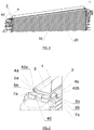
- FIG. 1 shows a perspective view of a fragment of a heat exchanger 20 with an air seal 1 mounted on a sideplate 40 of the heat exchanger 20
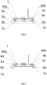
- Fig. 2 shows a perspective view of an enlarged detail "A" from Fig. 1
- Fig. 3 shows a front view of the air seal 1 in the correct position on the sideplate 40
- Fig. 4 shows a front view of the air seal in an incorrect position on the sideplate 40.
- This known air seal 1 has an elongate shape and comprises a profiled base 2 for connecting with the sideplate 40 of the heat exchanger 20 and for sealing thereof; the profiled base 2 has an longitudinal flat middle section 3 and first and second longitudinal edges 4a, 4b, bent towards that side of the air seal 1 which faces the side plate 40 after mounting.
- the hook 5a and the lock 5b have respectively bent middle walls 6a, 6b and end walls 7a, 7b.
- the air seal 1 is adapted to be attached on the sideplate 40 of the core of the heat exchanger 20 in such a way that, first, the first longitudinal edge 40a of the sideplate 40 is surrounded with the first longitudinal edge 4a and subsequently the opposite longitudinal edge 40b of the side plate 40 is surrounded the second longitudinal edge 4b of the air seal 1, and the lock 5b of the air seal 1 is blocked on said second longitudinal edge 40b of the sideplate 40.
- the air seal 1 has been correctly mounted on the longitudinal edges 40a, 40b of the sideplate 40 of the heat exchanger 20, as shown in Fig.
- the flat section 3 of the air seal 1 is positioned approximately parallel to the surface of the sideplate 40, and the bent edges 4a, 4b of the air seal 1 surround the longitudinal edges 40a, 40b of the side plate and are at a distance from the core 30 of the heat exchanger 20.
- elements of the heat exchanger core fins, tubes, etc.
- the air seal is correctly positioned during mounting, its second longitudinal edge 4b may be dislocated relative to the longitudinal edge 40b of the sideplate 40 during use, which may also cause damage of the core
- the purpose of the present invention is to provide an air seal for a heat exchanger which, on the one hand, is easy to mount on the sideplate of a heat exchanger, and on the other hand, ensures that the fins and other elements of the exchanger are protected against damage during mounting thereof.
- the purpose of the present invention is also to provide an air seal that allows protection against damage of the heat exchanger core and at the same time is easy to be made in one extrusion process.
- the air seal according to the invention can be precisely and securely mounted on the heat exchanger sideplate, especially relative to the heat exchanger core, allowing preventing undesired and damaging dislocation of the air seal relative to the core during the mounting and use.
- the term "elongate” defines the shape which has one dimension considerably longer that the other one, whereas the term “longitudinal” relating to individual elements defines the direction in which those elements are situated i.e. extending along the longer dimension.
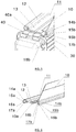
- FIG. 5 it shows a fragment of an automotive heat exchanger 20 comprising a core 30 and a sideplate 40 attached thereto, which has first and second edges 40a, 40b extending outwards and approximately parallel to the middle surface of the sideplate 40.
- the sideplate 40 of the heat exchanger 20 is sealed by means of an air seal 11 according to the invention, connected therewith.
- the air seal 11 has an elongate shape and comprises a profiled base 12 for connecting with the sideplate 40 of the heat exchanger 20 and for sealing with other component parts of a vehicle.
- the profiled base 12 has a longitudinal flat middle section 13 and, extending on the sides thereof, a first longitudinal edge 14a and a second longitudinal edge 14b.
- the longitudinal edges 14a, 14b are bent to that side of the air seal 11 which, after mounting, faces the sideplate 40 of the heat exchanger 20 and is further bent to the middle of the profiled base 12 in such a way that a longitudinal hook 15a adjusted to engage with the first longitudinal edge 40a of the side plate 40 is formed on the first longitudinal edge 14a of the air seal 11, whereas, on second longitudinal edge 14b of the sideplate 11, there is formed a longitudinal lock 15b adjusted to block the second longitudinal edge 40b of the sideplate 40 when mounting the air seal 11 on the sideplate 40.
- each of the hook 15a and the lock 15b has a middle wall 16a, 16b, respectively, approximately perpendicular to the flat middle section 13 of the air seal 11 and an end wall 17a,17b, respectively, extending from the middle wall 16a, 16b, respectively, towards the middle of the flat section 13 of the profiled base 12.
- the lock 15b is equipped with a longitudinal blocking lip 18b which is formed on the inner side of the middle wall 16b of the lock 15b.
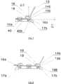
- the blocking lip 18b extends at a distance D1 from the end wall 17b of the lock 15b and protrudes from the inner side of said middle wall 16b to such a distance D2 that, between said blocking lip 18b, said end wall 17b and said middle wall 16b of the lock 15b there is defined a cavity 19 for receiving and blocking the second longitudinal edge 40b of the heat exchanger sideplate 40 when mounting the air seal 11 on the sideplate 40.
- the distance D1 between the blocking lip 18b and the end wall 17b of the lock 15b and the distance D2 to which the blocking lip 18b protrudes from the middle wall 17b, are selected such that, when mounting the air seal 11 on the sideplate 40 of the heat exchanger 20 and using thereof, the end wall 17b of the lock 15b is located at a distance from the core 30 of the heat exchanger 20 when the side edge 40b of the sideplate 40 abuts said blocking lip 18b. Consequently, the core 30 is secured against damage that could be caused by pressing the air seal 11 against the core 30.
- the profile of the air seal 11 for a heat exchanger 20 as modified according to the invention effectively prevents or at least limits the dislocation of said air seal towards the core 30 of the heat exchanger 20.
- the air seal 11 may also comprise at least one longitudinal wing 10 protruding away from the profiled base 12 in the direction opposite to the surface directed to the sideplate 40. Such a longitudinal wing 10 is intended to seal with other component parts of a vehicle.
- the air seal 11 may also comprise at least one longitudinal repelling rib 10a, extending away from the surface of the profiled base flat section 13 intended to face the sideplate 40 when mounted.
- the repelling lip 10a maintains the position of the air seal 11 relative to the sideplate 40 and ensures correct blocking of the second longitudinal edge 40b of the sideplate 40 in the lock 15b of the air seal 11.
- the entire air seal 11 with a modified profile according to the invention may be easily made in the process of extrusion of plastic, which ensures resilient properties.
- the method of mounting the seal 11 according to the invention on the sideplate 40 is the same as described in relation to the air seal 1 of the prior art described in the beginning, but when surrounding the second longitudinal edge 40b of the sideplate 40 with the second longitudinal edge 14b of the air seal 11, according to the invention, the second longitudinal edge 40b of the sideplate 40 is placed in the cavity 19 formed in the lock 15b of the air seal 11.
- the blocking lip 18b limits dislocation of the second longitudinal edge 40b from the top and prevents the air seal 11 from exerting pressure on the core 30.
Landscapes
- Engineering & Computer Science (AREA)
- Mechanical Engineering (AREA)
- Chemical & Material Sciences (AREA)
- Combustion & Propulsion (AREA)
- General Engineering & Computer Science (AREA)
- Physics & Mathematics (AREA)
- Thermal Sciences (AREA)
- Transportation (AREA)
- Heat-Exchange Devices With Radiators And Conduit Assemblies (AREA)
- Cooling, Air Intake And Gas Exhaust, And Fuel Tank Arrangements In Propulsion Units (AREA)
Priority Applications (3)
| Application Number | Priority Date | Filing Date | Title |
|---|---|---|---|
| EP16461565.0A EP3315890B1 (fr) | 2016-10-27 | 2016-10-27 | Joint d'étanchéité pour échangeur de chaleur d'automobile |
| PL16461565T PL3315890T3 (pl) | 2016-10-27 | 2016-10-27 | Uszczelnienie powietrzne do samochodowego wymiennika ciepła |
| PCT/EP2017/077682 WO2018078136A1 (fr) | 2016-10-27 | 2017-10-27 | Joint à air pour un échangeur thermique automobile |
Applications Claiming Priority (1)
| Application Number | Priority Date | Filing Date | Title |
|---|---|---|---|
| EP16461565.0A EP3315890B1 (fr) | 2016-10-27 | 2016-10-27 | Joint d'étanchéité pour échangeur de chaleur d'automobile |
Publications (2)
| Publication Number | Publication Date |
|---|---|
| EP3315890A1 true EP3315890A1 (fr) | 2018-05-02 |
| EP3315890B1 EP3315890B1 (fr) | 2020-01-29 |
Family
ID=57218845
Family Applications (1)
| Application Number | Title | Priority Date | Filing Date |
|---|---|---|---|
| EP16461565.0A Active EP3315890B1 (fr) | 2016-10-27 | 2016-10-27 | Joint d'étanchéité pour échangeur de chaleur d'automobile |
Country Status (3)
| Country | Link |
|---|---|
| EP (1) | EP3315890B1 (fr) |
| PL (1) | PL3315890T3 (fr) |
| WO (1) | WO2018078136A1 (fr) |
Cited By (2)
| Publication number | Priority date | Publication date | Assignee | Title |
|---|---|---|---|---|
| FR3104076A1 (fr) * | 2019-12-10 | 2021-06-11 | Renault S.A.S | Joint d’étanchéité sous radiateur |
| EP4035918A1 (fr) * | 2021-01-27 | 2022-08-03 | Volkswagen Ag | Échangeur de chaleur pourvu de baguette d'étanchéité |
Citations (5)
| Publication number | Priority date | Publication date | Assignee | Title |
|---|---|---|---|---|
| US4042741A (en) * | 1974-11-20 | 1977-08-16 | Draftex Development Ag | Channel-shaped flexible sealing strips |
| US4324826A (en) * | 1980-02-22 | 1982-04-13 | Draftex Development, A.G. | Finishing and sealing strips |
| DE29911505U1 (de) * | 1999-07-01 | 1999-09-16 | Behr Gmbh & Co, 70469 Stuttgart | Dichtung zwischen einem Wärmeübertrager und einer Gehäusewand |
| DE102004017339A1 (de) * | 2004-04-06 | 2005-10-27 | Behr Gmbh & Co. Kg | Dichtungsanordnung für einen Wärmeübertrager |
| FR2991245A1 (fr) * | 2012-05-31 | 2013-12-06 | Peugeot Citroen Automobiles Sa | Dispositif d'etancheite entre deux radiateurs de refroidissement implantes sur un vehicule, en particulier sur un vehicule a motorisation hybride |
Family Cites Families (1)
| Publication number | Priority date | Publication date | Assignee | Title |
|---|---|---|---|---|
| FR2775766B1 (fr) * | 1998-03-03 | 2000-05-05 | Valeo Thermique Moteur Sa | Echangeur de chaleur a ailettes protegees, notamment pour vehicule automobile |
-
2016
- 2016-10-27 PL PL16461565T patent/PL3315890T3/pl unknown
- 2016-10-27 EP EP16461565.0A patent/EP3315890B1/fr active Active
-
2017
- 2017-10-27 WO PCT/EP2017/077682 patent/WO2018078136A1/fr active Application Filing
Patent Citations (5)
| Publication number | Priority date | Publication date | Assignee | Title |
|---|---|---|---|---|
| US4042741A (en) * | 1974-11-20 | 1977-08-16 | Draftex Development Ag | Channel-shaped flexible sealing strips |
| US4324826A (en) * | 1980-02-22 | 1982-04-13 | Draftex Development, A.G. | Finishing and sealing strips |
| DE29911505U1 (de) * | 1999-07-01 | 1999-09-16 | Behr Gmbh & Co, 70469 Stuttgart | Dichtung zwischen einem Wärmeübertrager und einer Gehäusewand |
| DE102004017339A1 (de) * | 2004-04-06 | 2005-10-27 | Behr Gmbh & Co. Kg | Dichtungsanordnung für einen Wärmeübertrager |
| FR2991245A1 (fr) * | 2012-05-31 | 2013-12-06 | Peugeot Citroen Automobiles Sa | Dispositif d'etancheite entre deux radiateurs de refroidissement implantes sur un vehicule, en particulier sur un vehicule a motorisation hybride |
Cited By (3)
| Publication number | Priority date | Publication date | Assignee | Title |
|---|---|---|---|---|
| FR3104076A1 (fr) * | 2019-12-10 | 2021-06-11 | Renault S.A.S | Joint d’étanchéité sous radiateur |
| WO2021115752A1 (fr) * | 2019-12-10 | 2021-06-17 | Renault S.A.S | Joint d'étanchéité sous radiateur |
| EP4035918A1 (fr) * | 2021-01-27 | 2022-08-03 | Volkswagen Ag | Échangeur de chaleur pourvu de baguette d'étanchéité |
Also Published As
| Publication number | Publication date |
|---|---|
| EP3315890B1 (fr) | 2020-01-29 |
| PL3315890T3 (pl) | 2020-12-14 |
| WO2018078136A1 (fr) | 2018-05-03 |
Similar Documents
| Publication | Publication Date | Title |
|---|---|---|
| EP3315890B1 (fr) | Joint d'étanchéité pour échangeur de chaleur d'automobile | |
| US9248787B2 (en) | Vehicle interior part including a clip mount having a protrusion to guide a sealing member | |
| CN104701786A (zh) | 用于线缆的固定设备 | |
| US11371284B2 (en) | Screen attachment adapter | |
| US20090007511A1 (en) | Window Unit Having Decorative Strip Mounted Thereon | |
| US11536302B2 (en) | Fastening clip for fastening an attachment component on a carrier edge | |
| CN108352648A (zh) | 用于保持插拔式连接器模块的保持框架 | |
| KR20170143421A (ko) | 열 교환기용 압인된 헤더 | |
| ES2383817T3 (es) | Sistema de fijación para una caja de persiana arrollable | |
| US20170013737A1 (en) | Housing | |
| US9593892B2 (en) | Heat exchanger and retention element | |
| US6865092B2 (en) | Front part for electronic plug-in modules | |
| EP3346168B1 (fr) | Joint d'étanchéité | |
| US20100230426A1 (en) | Protective caps for wiper blades | |
| US11542970B2 (en) | Edge protector | |
| JP6858740B2 (ja) | ウェザーストリップ、ウェザーストリップの取付構造、およびウェザーストリップの取付方法 | |
| JP6573159B2 (ja) | フロントパネルシール構造 | |
| KR101427228B1 (ko) | 타이 클램프 | |
| US20200148040A1 (en) | Mounting for a Flat Element of a Sun Protection or Dimming Device, and Sun Protection or Dimming Device | |
| JP6440987B2 (ja) | 目地用バッカーおよび目地止水構造 | |
| JP2015032784A (ja) | ターミナル保護構造 | |
| US9228657B2 (en) | Sealing element | |
| KR101566500B1 (ko) | 인서트 너트 | |
| JP2008038366A (ja) | クリップ | |
| KR20170133885A (ko) | 창틀용 방수장치 및 이를 이용한 창틀의 방수공사방법 |
Legal Events
| Date | Code | Title | Description |
|---|---|---|---|
| PUAI | Public reference made under article 153(3) epc to a published international application that has entered the european phase |
Free format text: ORIGINAL CODE: 0009012 |
|
| STAA | Information on the status of an ep patent application or granted ep patent |
Free format text: STATUS: THE APPLICATION HAS BEEN PUBLISHED |
|
| AK | Designated contracting states |
Kind code of ref document: A1 Designated state(s): AL AT BE BG CH CY CZ DE DK EE ES FI FR GB GR HR HU IE IS IT LI LT LU LV MC MK MT NL NO PL PT RO RS SE SI SK SM TR |
|
| AX | Request for extension of the european patent |
Extension state: BA ME |
|
| STAA | Information on the status of an ep patent application or granted ep patent |
Free format text: STATUS: REQUEST FOR EXAMINATION WAS MADE |
|
| 17P | Request for examination filed |
Effective date: 20190312 |
|
| RBV | Designated contracting states (corrected) |
Designated state(s): AL AT BE BG CH CY CZ DE DK EE ES FI FR GB GR HR HU IE IS IT LI LT LU LV MC MK MT NL NO PL PT RO RS SE SI SK SM TR |
|
| GRAP | Despatch of communication of intention to grant a patent |
Free format text: ORIGINAL CODE: EPIDOSNIGR1 |
|
| STAA | Information on the status of an ep patent application or granted ep patent |
Free format text: STATUS: GRANT OF PATENT IS INTENDED |
|
| INTG | Intention to grant announced |
Effective date: 20190827 |
|
| GRAS | Grant fee paid |
Free format text: ORIGINAL CODE: EPIDOSNIGR3 |
|
| GRAA | (expected) grant |
Free format text: ORIGINAL CODE: 0009210 |
|
| STAA | Information on the status of an ep patent application or granted ep patent |
Free format text: STATUS: THE PATENT HAS BEEN GRANTED |
|
| AK | Designated contracting states |
Kind code of ref document: B1 Designated state(s): AL AT BE BG CH CY CZ DE DK EE ES FI FR GB GR HR HU IE IS IT LI LT LU LV MC MK MT NL NO PL PT RO RS SE SI SK SM TR |
|
| REG | Reference to a national code |
Ref country code: GB Ref legal event code: FG4D |
|
| REG | Reference to a national code |
Ref country code: CH Ref legal event code: EP |
|
| REG | Reference to a national code |
Ref country code: AT Ref legal event code: REF Ref document number: 1228798 Country of ref document: AT Kind code of ref document: T Effective date: 20200215 |
|
| REG | Reference to a national code |
Ref country code: IE Ref legal event code: FG4D |
|
| REG | Reference to a national code |
Ref country code: DE Ref legal event code: R096 Ref document number: 602016028657 Country of ref document: DE |
|
| REG | Reference to a national code |
Ref country code: NL Ref legal event code: MP Effective date: 20200129 |
|
| PG25 | Lapsed in a contracting state [announced via postgrant information from national office to epo] |
Ref country code: RS Free format text: LAPSE BECAUSE OF FAILURE TO SUBMIT A TRANSLATION OF THE DESCRIPTION OR TO PAY THE FEE WITHIN THE PRESCRIBED TIME-LIMIT Effective date: 20200129 Ref country code: FI Free format text: LAPSE BECAUSE OF FAILURE TO SUBMIT A TRANSLATION OF THE DESCRIPTION OR TO PAY THE FEE WITHIN THE PRESCRIBED TIME-LIMIT Effective date: 20200129 Ref country code: NO Free format text: LAPSE BECAUSE OF FAILURE TO SUBMIT A TRANSLATION OF THE DESCRIPTION OR TO PAY THE FEE WITHIN THE PRESCRIBED TIME-LIMIT Effective date: 20200429 Ref country code: PT Free format text: LAPSE BECAUSE OF FAILURE TO SUBMIT A TRANSLATION OF THE DESCRIPTION OR TO PAY THE FEE WITHIN THE PRESCRIBED TIME-LIMIT Effective date: 20200621 |
|
| REG | Reference to a national code |
Ref country code: LT Ref legal event code: MG4D |
|
| PG25 | Lapsed in a contracting state [announced via postgrant information from national office to epo] |
Ref country code: HR Free format text: LAPSE BECAUSE OF FAILURE TO SUBMIT A TRANSLATION OF THE DESCRIPTION OR TO PAY THE FEE WITHIN THE PRESCRIBED TIME-LIMIT Effective date: 20200129 Ref country code: BG Free format text: LAPSE BECAUSE OF FAILURE TO SUBMIT A TRANSLATION OF THE DESCRIPTION OR TO PAY THE FEE WITHIN THE PRESCRIBED TIME-LIMIT Effective date: 20200429 Ref country code: SE Free format text: LAPSE BECAUSE OF FAILURE TO SUBMIT A TRANSLATION OF THE DESCRIPTION OR TO PAY THE FEE WITHIN THE PRESCRIBED TIME-LIMIT Effective date: 20200129 Ref country code: LV Free format text: LAPSE BECAUSE OF FAILURE TO SUBMIT A TRANSLATION OF THE DESCRIPTION OR TO PAY THE FEE WITHIN THE PRESCRIBED TIME-LIMIT Effective date: 20200129 Ref country code: IS Free format text: LAPSE BECAUSE OF FAILURE TO SUBMIT A TRANSLATION OF THE DESCRIPTION OR TO PAY THE FEE WITHIN THE PRESCRIBED TIME-LIMIT Effective date: 20200529 Ref country code: GR Free format text: LAPSE BECAUSE OF FAILURE TO SUBMIT A TRANSLATION OF THE DESCRIPTION OR TO PAY THE FEE WITHIN THE PRESCRIBED TIME-LIMIT Effective date: 20200430 |
|
| PG25 | Lapsed in a contracting state [announced via postgrant information from national office to epo] |
Ref country code: NL Free format text: LAPSE BECAUSE OF FAILURE TO SUBMIT A TRANSLATION OF THE DESCRIPTION OR TO PAY THE FEE WITHIN THE PRESCRIBED TIME-LIMIT Effective date: 20200129 |
|
| PG25 | Lapsed in a contracting state [announced via postgrant information from national office to epo] |
Ref country code: SK Free format text: LAPSE BECAUSE OF FAILURE TO SUBMIT A TRANSLATION OF THE DESCRIPTION OR TO PAY THE FEE WITHIN THE PRESCRIBED TIME-LIMIT Effective date: 20200129 Ref country code: RO Free format text: LAPSE BECAUSE OF FAILURE TO SUBMIT A TRANSLATION OF THE DESCRIPTION OR TO PAY THE FEE WITHIN THE PRESCRIBED TIME-LIMIT Effective date: 20200129 Ref country code: CZ Free format text: LAPSE BECAUSE OF FAILURE TO SUBMIT A TRANSLATION OF THE DESCRIPTION OR TO PAY THE FEE WITHIN THE PRESCRIBED TIME-LIMIT Effective date: 20200129 Ref country code: ES Free format text: LAPSE BECAUSE OF FAILURE TO SUBMIT A TRANSLATION OF THE DESCRIPTION OR TO PAY THE FEE WITHIN THE PRESCRIBED TIME-LIMIT Effective date: 20200129 Ref country code: DK Free format text: LAPSE BECAUSE OF FAILURE TO SUBMIT A TRANSLATION OF THE DESCRIPTION OR TO PAY THE FEE WITHIN THE PRESCRIBED TIME-LIMIT Effective date: 20200129 Ref country code: LT Free format text: LAPSE BECAUSE OF FAILURE TO SUBMIT A TRANSLATION OF THE DESCRIPTION OR TO PAY THE FEE WITHIN THE PRESCRIBED TIME-LIMIT Effective date: 20200129 Ref country code: EE Free format text: LAPSE BECAUSE OF FAILURE TO SUBMIT A TRANSLATION OF THE DESCRIPTION OR TO PAY THE FEE WITHIN THE PRESCRIBED TIME-LIMIT Effective date: 20200129 Ref country code: SM Free format text: LAPSE BECAUSE OF FAILURE TO SUBMIT A TRANSLATION OF THE DESCRIPTION OR TO PAY THE FEE WITHIN THE PRESCRIBED TIME-LIMIT Effective date: 20200129 |
|
| REG | Reference to a national code |
Ref country code: DE Ref legal event code: R097 Ref document number: 602016028657 Country of ref document: DE |
|
| REG | Reference to a national code |
Ref country code: AT Ref legal event code: MK05 Ref document number: 1228798 Country of ref document: AT Kind code of ref document: T Effective date: 20200129 |
|
| PLBE | No opposition filed within time limit |
Free format text: ORIGINAL CODE: 0009261 |
|
| STAA | Information on the status of an ep patent application or granted ep patent |
Free format text: STATUS: NO OPPOSITION FILED WITHIN TIME LIMIT |
|
| 26N | No opposition filed |
Effective date: 20201030 |
|
| PG25 | Lapsed in a contracting state [announced via postgrant information from national office to epo] |
Ref country code: AT Free format text: LAPSE BECAUSE OF FAILURE TO SUBMIT A TRANSLATION OF THE DESCRIPTION OR TO PAY THE FEE WITHIN THE PRESCRIBED TIME-LIMIT Effective date: 20200129 Ref country code: IT Free format text: LAPSE BECAUSE OF FAILURE TO SUBMIT A TRANSLATION OF THE DESCRIPTION OR TO PAY THE FEE WITHIN THE PRESCRIBED TIME-LIMIT Effective date: 20200129 |
|
| PG25 | Lapsed in a contracting state [announced via postgrant information from national office to epo] |
Ref country code: SI Free format text: LAPSE BECAUSE OF FAILURE TO SUBMIT A TRANSLATION OF THE DESCRIPTION OR TO PAY THE FEE WITHIN THE PRESCRIBED TIME-LIMIT Effective date: 20200129 |
|
| REG | Reference to a national code |
Ref country code: CH Ref legal event code: PL |
|
| GBPC | Gb: european patent ceased through non-payment of renewal fee |
Effective date: 20201027 |
|
| PG25 | Lapsed in a contracting state [announced via postgrant information from national office to epo] |
Ref country code: LU Free format text: LAPSE BECAUSE OF NON-PAYMENT OF DUE FEES Effective date: 20201027 Ref country code: MC Free format text: LAPSE BECAUSE OF FAILURE TO SUBMIT A TRANSLATION OF THE DESCRIPTION OR TO PAY THE FEE WITHIN THE PRESCRIBED TIME-LIMIT Effective date: 20200129 |
|
| REG | Reference to a national code |
Ref country code: BE Ref legal event code: MM Effective date: 20201031 |
|
| PG25 | Lapsed in a contracting state [announced via postgrant information from national office to epo] |
Ref country code: LI Free format text: LAPSE BECAUSE OF NON-PAYMENT OF DUE FEES Effective date: 20201031 Ref country code: GB Free format text: LAPSE BECAUSE OF NON-PAYMENT OF DUE FEES Effective date: 20201027 Ref country code: BE Free format text: LAPSE BECAUSE OF NON-PAYMENT OF DUE FEES Effective date: 20201031 Ref country code: CH Free format text: LAPSE BECAUSE OF NON-PAYMENT OF DUE FEES Effective date: 20201031 |
|
| PG25 | Lapsed in a contracting state [announced via postgrant information from national office to epo] |
Ref country code: IE Free format text: LAPSE BECAUSE OF NON-PAYMENT OF DUE FEES Effective date: 20201027 |
|
| PGFP | Annual fee paid to national office [announced via postgrant information from national office to epo] |
Ref country code: PL Payment date: 20210927 Year of fee payment: 6 |
|
| PG25 | Lapsed in a contracting state [announced via postgrant information from national office to epo] |
Ref country code: TR Free format text: LAPSE BECAUSE OF FAILURE TO SUBMIT A TRANSLATION OF THE DESCRIPTION OR TO PAY THE FEE WITHIN THE PRESCRIBED TIME-LIMIT Effective date: 20200129 Ref country code: MT Free format text: LAPSE BECAUSE OF FAILURE TO SUBMIT A TRANSLATION OF THE DESCRIPTION OR TO PAY THE FEE WITHIN THE PRESCRIBED TIME-LIMIT Effective date: 20200129 Ref country code: CY Free format text: LAPSE BECAUSE OF FAILURE TO SUBMIT A TRANSLATION OF THE DESCRIPTION OR TO PAY THE FEE WITHIN THE PRESCRIBED TIME-LIMIT Effective date: 20200129 |
|
| PG25 | Lapsed in a contracting state [announced via postgrant information from national office to epo] |
Ref country code: MK Free format text: LAPSE BECAUSE OF FAILURE TO SUBMIT A TRANSLATION OF THE DESCRIPTION OR TO PAY THE FEE WITHIN THE PRESCRIBED TIME-LIMIT Effective date: 20200129 Ref country code: AL Free format text: LAPSE BECAUSE OF FAILURE TO SUBMIT A TRANSLATION OF THE DESCRIPTION OR TO PAY THE FEE WITHIN THE PRESCRIBED TIME-LIMIT Effective date: 20200129 |
|
| P01 | Opt-out of the competence of the unified patent court (upc) registered |
Effective date: 20230528 |
|
| PGFP | Annual fee paid to national office [announced via postgrant information from national office to epo] |
Ref country code: FR Payment date: 20231023 Year of fee payment: 8 Ref country code: DE Payment date: 20231011 Year of fee payment: 8 |
|
| PG25 | Lapsed in a contracting state [announced via postgrant information from national office to epo] |
Ref country code: PL Free format text: LAPSE BECAUSE OF NON-PAYMENT OF DUE FEES Effective date: 20221027 |