EP3315869B1 - Ceiling installation type air conditioner - Google Patents
Ceiling installation type air conditioner Download PDFInfo
- Publication number
- EP3315869B1 EP3315869B1 EP16814337.8A EP16814337A EP3315869B1 EP 3315869 B1 EP3315869 B1 EP 3315869B1 EP 16814337 A EP16814337 A EP 16814337A EP 3315869 B1 EP3315869 B1 EP 3315869B1
- Authority
- EP
- European Patent Office
- Prior art keywords
- heat exchange
- exchange section
- air conditioner
- air outlet
- plate
- Prior art date
- Legal status (The legal status is an assumption and is not a legal conclusion. Google has not performed a legal analysis and makes no representation as to the accuracy of the status listed.)
- Active
Links
Images


Classifications
-
- F—MECHANICAL ENGINEERING; LIGHTING; HEATING; WEAPONS; BLASTING
- F24—HEATING; RANGES; VENTILATING
- F24F—AIR-CONDITIONING; AIR-HUMIDIFICATION; VENTILATION; USE OF AIR CURRENTS FOR SCREENING
- F24F1/00—Room units for air-conditioning, e.g. separate or self-contained units or units receiving primary air from a central station
- F24F1/0007—Indoor units, e.g. fan coil units
- F24F1/0059—Indoor units, e.g. fan coil units characterised by heat exchangers
- F24F1/0067—Indoor units, e.g. fan coil units characterised by heat exchangers by the shape of the heat exchangers or of parts thereof, e.g. of their fins
-
- F—MECHANICAL ENGINEERING; LIGHTING; HEATING; WEAPONS; BLASTING
- F28—HEAT EXCHANGE IN GENERAL
- F28D—HEAT-EXCHANGE APPARATUS, NOT PROVIDED FOR IN ANOTHER SUBCLASS, IN WHICH THE HEAT-EXCHANGE MEDIA DO NOT COME INTO DIRECT CONTACT
- F28D1/00—Heat-exchange apparatus having stationary conduit assemblies for one heat-exchange medium only, the media being in contact with different sides of the conduit wall, in which the other heat-exchange medium is a large body of fluid, e.g. domestic or motor car radiators
- F28D1/02—Heat-exchange apparatus having stationary conduit assemblies for one heat-exchange medium only, the media being in contact with different sides of the conduit wall, in which the other heat-exchange medium is a large body of fluid, e.g. domestic or motor car radiators with heat-exchange conduits immersed in the body of fluid
- F28D1/04—Heat-exchange apparatus having stationary conduit assemblies for one heat-exchange medium only, the media being in contact with different sides of the conduit wall, in which the other heat-exchange medium is a large body of fluid, e.g. domestic or motor car radiators with heat-exchange conduits immersed in the body of fluid with tubular conduits
- F28D1/047—Heat-exchange apparatus having stationary conduit assemblies for one heat-exchange medium only, the media being in contact with different sides of the conduit wall, in which the other heat-exchange medium is a large body of fluid, e.g. domestic or motor car radiators with heat-exchange conduits immersed in the body of fluid with tubular conduits the conduits being bent, e.g. in a serpentine or zig-zag
-
- F—MECHANICAL ENGINEERING; LIGHTING; HEATING; WEAPONS; BLASTING
- F24—HEATING; RANGES; VENTILATING
- F24F—AIR-CONDITIONING; AIR-HUMIDIFICATION; VENTILATION; USE OF AIR CURRENTS FOR SCREENING
- F24F1/00—Room units for air-conditioning, e.g. separate or self-contained units or units receiving primary air from a central station
- F24F1/0007—Indoor units, e.g. fan coil units
- F24F1/0043—Indoor units, e.g. fan coil units characterised by mounting arrangements
- F24F1/0047—Indoor units, e.g. fan coil units characterised by mounting arrangements mounted in the ceiling or at the ceiling
-
- F—MECHANICAL ENGINEERING; LIGHTING; HEATING; WEAPONS; BLASTING
- F24—HEATING; RANGES; VENTILATING
- F24F—AIR-CONDITIONING; AIR-HUMIDIFICATION; VENTILATION; USE OF AIR CURRENTS FOR SCREENING
- F24F13/00—Details common to, or for air-conditioning, air-humidification, ventilation or use of air currents for screening
- F24F13/30—Arrangement or mounting of heat-exchangers
-
- F—MECHANICAL ENGINEERING; LIGHTING; HEATING; WEAPONS; BLASTING
- F24—HEATING; RANGES; VENTILATING
- F24F—AIR-CONDITIONING; AIR-HUMIDIFICATION; VENTILATION; USE OF AIR CURRENTS FOR SCREENING
- F24F13/00—Details common to, or for air-conditioning, air-humidification, ventilation or use of air currents for screening
- F24F13/32—Supports for air-conditioning, air-humidification or ventilation units
-
- F—MECHANICAL ENGINEERING; LIGHTING; HEATING; WEAPONS; BLASTING
- F28—HEAT EXCHANGE IN GENERAL
- F28D—HEAT-EXCHANGE APPARATUS, NOT PROVIDED FOR IN ANOTHER SUBCLASS, IN WHICH THE HEAT-EXCHANGE MEDIA DO NOT COME INTO DIRECT CONTACT
- F28D1/00—Heat-exchange apparatus having stationary conduit assemblies for one heat-exchange medium only, the media being in contact with different sides of the conduit wall, in which the other heat-exchange medium is a large body of fluid, e.g. domestic or motor car radiators
- F28D1/02—Heat-exchange apparatus having stationary conduit assemblies for one heat-exchange medium only, the media being in contact with different sides of the conduit wall, in which the other heat-exchange medium is a large body of fluid, e.g. domestic or motor car radiators with heat-exchange conduits immersed in the body of fluid
- F28D1/04—Heat-exchange apparatus having stationary conduit assemblies for one heat-exchange medium only, the media being in contact with different sides of the conduit wall, in which the other heat-exchange medium is a large body of fluid, e.g. domestic or motor car radiators with heat-exchange conduits immersed in the body of fluid with tubular conduits
- F28D1/0408—Multi-circuit heat exchangers, e.g. integrating different heat exchange sections in the same unit or heat exchangers for more than two fluids
- F28D1/0417—Multi-circuit heat exchangers, e.g. integrating different heat exchange sections in the same unit or heat exchangers for more than two fluids with particular circuits for the same heat exchange medium, e.g. with the heat exchange medium flowing through sections having different heat exchange capacities or for heating/cooling the heat exchange medium at different temperatures
-
- F—MECHANICAL ENGINEERING; LIGHTING; HEATING; WEAPONS; BLASTING
- F28—HEAT EXCHANGE IN GENERAL
- F28D—HEAT-EXCHANGE APPARATUS, NOT PROVIDED FOR IN ANOTHER SUBCLASS, IN WHICH THE HEAT-EXCHANGE MEDIA DO NOT COME INTO DIRECT CONTACT
- F28D1/00—Heat-exchange apparatus having stationary conduit assemblies for one heat-exchange medium only, the media being in contact with different sides of the conduit wall, in which the other heat-exchange medium is a large body of fluid, e.g. domestic or motor car radiators
- F28D1/02—Heat-exchange apparatus having stationary conduit assemblies for one heat-exchange medium only, the media being in contact with different sides of the conduit wall, in which the other heat-exchange medium is a large body of fluid, e.g. domestic or motor car radiators with heat-exchange conduits immersed in the body of fluid
- F28D1/04—Heat-exchange apparatus having stationary conduit assemblies for one heat-exchange medium only, the media being in contact with different sides of the conduit wall, in which the other heat-exchange medium is a large body of fluid, e.g. domestic or motor car radiators with heat-exchange conduits immersed in the body of fluid with tubular conduits
- F28D1/0408—Multi-circuit heat exchangers, e.g. integrating different heat exchange sections in the same unit or heat exchangers for more than two fluids
- F28D1/0426—Multi-circuit heat exchangers, e.g. integrating different heat exchange sections in the same unit or heat exchangers for more than two fluids with units having particular arrangement relative to the large body of fluid, e.g. with interleaved units or with adjacent heat exchange units in common air flow or with units extending at an angle to each other or with units arranged around a central element
-
- F—MECHANICAL ENGINEERING; LIGHTING; HEATING; WEAPONS; BLASTING
- F28—HEAT EXCHANGE IN GENERAL
- F28F—DETAILS OF HEAT-EXCHANGE AND HEAT-TRANSFER APPARATUS, OF GENERAL APPLICATION
- F28F1/00—Tubular elements; Assemblies of tubular elements
- F28F1/10—Tubular elements and assemblies thereof with means for increasing heat-transfer area, e.g. with fins, with projections, with recesses
- F28F1/12—Tubular elements and assemblies thereof with means for increasing heat-transfer area, e.g. with fins, with projections, with recesses the means being only outside the tubular element
- F28F1/24—Tubular elements and assemblies thereof with means for increasing heat-transfer area, e.g. with fins, with projections, with recesses the means being only outside the tubular element and extending transversely
- F28F1/32—Tubular elements and assemblies thereof with means for increasing heat-transfer area, e.g. with fins, with projections, with recesses the means being only outside the tubular element and extending transversely the means having portions engaging further tubular elements
- F28F1/325—Fins with openings
Definitions
- Embodiments according to the present invention relate to a ceiling installation type air conditioner comprising a heat exchanger.
- An indoor unit of a ceiling installation type air conditioner (i.e., ceiling-installed air conditioner) is installed in ceiling space such that the indoor unit is suspended from the characteristics of a beam provided on an attic or is buried in the attic.
- the inside of the indoor unit is partitioned with a partition plate into a heat exchange chamber and a blower chamber.
- a heat exchanger is disposed in the heat exchange chamber, and a blower for sending air to the heat exchanger is disposed in the blower chamber.
- the heat exchanger includes plural heat transfer tubes through which refrigerant flows and plural fins that are thermally connected to the heat transfer tubes.
- the heat exchanger is in the form of a flat plate as a whole. Further, the heat exchanger is accommodated in the heat exchange chamber in the state of being largely inclined with respect to the blower in order to efficiently receive the air sent from the blower and to minimize the height dimension of the indoor unit.
- EP 2 722 609 A1 , EP 2 402 669 A2 , and US 4, 000,779 A disclose air conditioners.
- Patent Document 1 Japanese Unexamined Patent Application Publication No. 2006-343043
- the heat exchanger in the form of a flat plate is disposed in the heat exchange chamber so as to be inclined in the conventional air conditioner, much wasted space is inevitably generated inside the heat exchange chamber, which causes increase in depth dimension.
- the outer dimension of the heat exchange chamber increases in proportion to capacity.
- larger space is required inside the heat exchange chamber as capacity of the heat exchanger increases.
- the heat exchanger in the form of a flat plate is disposed in the heat exchange chamber so as to be inclined in the conventional air conditioner, the distance from the blower greatly differs between the front end portion and the rear end portion of the heat exchanger in the conventional air conditioner.
- the volume of air passing through the heat exchanger easily varies. Variation in volume of the air passing through the heat exchanger degrades performance of the heat exchanger.
- the conventional air conditioner leaves room for improvement in order to fully demonstrate the performance of the heat exchanger.
- an aspect of the present invention provides a ceiling-mounted air conditioner that is compact and has high heat exchange efficiency.
- the present invention provides a ceiling installation type air conditioner according to claim 1.
- the plate-shaped fins has a substantially parallelogram shape.
- a long side of the plate-shaped fins of the first heat exchange section on the blower chamber side is in contact with a short side of the plate-shaped fins of the second heat exchange section on the air outlet side without any gap
- a short side of the plate-shaped fins of the first heat exchange section on the air outlet side is in contact with a short side of the plate-shaped fins of the third heat exchange section on the air outlet side without any gap.
- first heat exchange section is closest to the air outlet out of the first heat exchange section, the second heat exchange section, and the third heat exchange section, and number of the heat transfer tubes provided for the first heat exchange section is larger than the number of the heat transfer tubes provided for each of the second heat exchange section and the third heat exchange section.
- an interval at which the plate-shaped fins of the first heat exchange sections are arranged is narrower than an interval at which the plate- shaped fins of each of the second heat exchange section and the third heat exchange section are arranged.
- slits are provided only in the plate-shaped fins of the first heat exchange section.
- a pipe diameter of the heat transfer tubes of the first heat exchange section is larger than a pipe diameter of the heat transfer tubes of the second heat exchange section and the third heat exchange section.
- first heat exchange section, the second heat exchange section, and the third heat exchange section are integrally formed.
- the second heat exchange section is disposed at an upper portion of the heat exchange chamber
- the third heat exchange section is disposed at a lower portion of the heat exchange chamber
- angle difference is provided in such a manner that an inclination angle of the second heat exchange section is smaller than an inclination angle of the third heat exchange section.
- the first heat exchange section is inclined in such a manner that an upper end portion of the first heat exchange section is positioned on a windward side of a lower end portion of the first heat exchange section.
- an end portion of a short side of the plate-shaped fins of the third heat exchange section on a side of the air outlet is protruded toward the air outlet more than an end portion of a short side positioned at a lower portion of the plate-shaped fins of the first heat exchange section.
- a shortest distance between the air outlet and an end portion on a side of the air outlet of a short side positioned at a lower portion of the plate-shaped fins of the first heat exchange section is longer than a shortest distance between the air outlet and an end portion on a side of the air outlet of a short side positioned at a lower portion of the plate-shaped fins of the third heat exchange section.
- the ceiling installation type air conditioner of the first embodiment will be described with by referring to Fig. 1 to Fig. 5 .
- Fig. 1 illustrates the ceiling installation type air conditioner 1 of the embodiment.
- An indoor unit 2 of the ceiling installation type air conditioner 1 is installed, e.g., on an attic of a building.
- the attic of the embodiment is defined as ceiling space between a ceiling plate and a beam of the building.
- the indoor unit 2 is formed in the shape of a rectangular flat box having a depth dimension D, a width dimension W, and a height dimension H.
- the indoor unit 2 includes a metallic housing 20.
- the housing 20 is an outer periphery of the indoor unit 2.
- the housing 20 includes a top plate 21, a first side plate 22a, a second side plate 22b, a first bottom plate 23a, a second bottom plate 23b, a front frame 24, a rear frame 25, and a partition plate 26.
- the partition plate 26 of the ceiling installation type air conditioner 1 partitions the interior of the housing 20 into two chambers that are a blower chamber 3 and a heat exchange chamber 4.
- the blower chamber 3 has an air inlet 27 formed in the rear frame 25.
- a blower 5 is accommodated in the blower chamber 3.
- the blower 5 includes a fan motor 51, fan cases 52a and 52b, and multi-blade fans 53a and 53b housed inside the fan cases 52a and 52b.
- Respective suction ports 54a and 54b are provided on both side surfaces of the fan cases 52a and 52b.
- the partition plate 26 is provided with blowout ports 55a and 55b.
- the fan motor 51 includes two rotating shafts 51a and 51b that are coaxially protruded from both side surfaces thereof.
- the multi-blade fans 53a and 53b are attached to the respective rotating shafts 51a and 51b.
- the heat exchange chamber 4 includes a machine room 6 and an air outlet 28 formed in the front frame 24.
- the machine room 6 is partitioned from the heat exchange chamber 4 with a machine-room partition plate 61, and accommodates a drain pump and a refrigerant distributor.
- the blower chamber 3 and the heat exchange chamber 4 are connected to each other via the blower 5. Specifically, both are spatially connected with each other such that air in the blower chamber 3 can flow into the heat exchange chamber 4 through the blower 5.
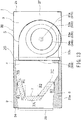
- a heat exchanger 7 and a drain pan 8 are disposed in the heat exchange chamber 4 as shown in Fig. 3 .
- the heat exchanger 7 and the drain pan 8 are housed in the heat exchange chamber 4 of the housing 20.
- the heat exchanger 7 extends in the width direction of the indoor unit 2 (i.e., in the width direction of the housing 20), and is interposed between the machine-room partition plate 61 and the side plate 22a.
- the drain pan 8 is disposed below the heat exchanger 7.
- the drain pan 8 is a heat insulating material such as expanded polystyrene.
- the drain pan 8 supports the heat exchanger 7 from the lower side, and receives drain water dripping from the heat exchanger 7.
- the lower surface of the drain pan 8 is covered with the first bottom plate 23a.
- the drain pan 8 cooperates with a heat insulating material 9 to surround the heat exchanger 7.
- the heat insulating material 9 is disposed above the heat exchanger 7, and is provided on the inner surface of the top plate 21 and in the heat exchange chamber 4.
- the heat exchanger 7 of the embodiment includes a first heat exchange section 7A, a second heat exchange section 7B, and a third heat exchanging portion 7C.
- the first heat exchange section 7A, the second heat exchange section 7B, and the third heat exchange section 7C are disposed so as to protrude toward the air outlet 28 in a convex shape.
- the first heat exchange section 7A stands inside the heat exchange chamber 4 so as to face substantially parallel to the partition plate 26 and the blowout ports 55a and 55b of the blower 5. Out of the first heat exchange section 7A, the second heat exchange section 7B, and the third heat exchange section 7C, the first heat exchange section 7A is the closest to the air outlet 28 in the embodiment.
- the second heat exchange section 7B is located at the upper portion of the heat exchange chamber 4, and extends in the depth direction of the indoor unit 2 so as to be separated away from the blower 5 in a cross-sectional view.
- the second heat exchange section 7B is inclined slightly downward as separating from the blower 5.
- the second heat exchange section 7B is inclined slightly downward as it approaches the air outlet 28.
- the front end (i.e., the side of the air outlet 28) of the second heat exchange section 7B is spatially continuous with the upper end of the first heat exchange section 7A.
- the third heat exchange section 7C is positioned at the lower portion of the heat exchange chamber 4, and extends in the depth direction of the indoor unit 2 so as to be separated away from the blower 5 in a cross-sectional view.
- the third heat exchange section 7C is inclined slightly upward as separating from the blower 5.
- the third heat exchange section 7C is inclined slightly upward as it approaches the air outlet 28.
- the front end (i.e., the side of the air outlet 28) of the third heat exchange section 7C is spatially continuous with the lower end of the first heat exchange section 7A.
- the heat exchanger 7 includes: the first heat exchange section 7A that stands so as to face the blowout ports 55a and 55b and the partition plate 26; the second heat exchange section 7B that extends obliquely upward from the upper end of the first heat exchange section 7A toward the blower 5; and the third heat exchange section 7C that extends obliquely downward from the lower end of the first heat exchange section 7A toward the blower 5.
- the first to third heat exchange sections 7A, 7B, and 7C of the first embodiment are combined so as to be substantially in the form of an angled bracket or a gate. That is, the heat exchanger 7 is disposed so as to have a convex shape protruding toward the leeward side with respect to wind sent from the blower chamber 3, and is disposed so as to have a substantially concave shape recessed toward the windward side.
- first to third heat exchange sections 7A, 7B, and 7C are disposed in a substantially trapezoidal shape including a smaller base (a top) and a pair of leg portions when the indoor unit 2 is viewed from the side.
- the first heat exchange section 7A is disposed at the portion (side) corresponding to the smaller base and the second and third heat exchange sections 7B and 7C are disposed at the respective portions (sides) corresponding to the pair of leg portions in such a manner that the substantially trapezoidal shape is formed as a whole with its longer portion opened.
- the heat exchanger 7 of the ceiling installation type air conditioner 1 is a fin-tube type heat exchanger that is a combination of plate-like fins and heat transfer tubes.
- Each of the first to third heat exchange sections 7A, 7B, and 7C of the embodiment includes plural elongated fins 71 and plural heat transfer tubes 72 through which a refrigerant flows.
- the fins 71 of the ceiling installation type air conditioner 1 are, e.g., a quadrilateral plate made of aluminum and has a pair of long sides 71L and a pair of short sides 71S.
- the long sides 71L are parallel to each other.
- the short sides 71S are parallel to each other, and extend obliquely so as to intersect the long sides 71L.
- the fins 71 have a parallelogram shape in which two pairs of opposite sides are parallel to each other.
- the fins 71 are provided with plural engagement holes 73.
- the engagement holes 73 have a cylindrical flange portion that is pierced by, e.g., applying a burring process to the fins 71 and rises from the fins 71.
- the engagement holes 73 are arranged in eight rows in the direction along the long sides 71L of the fins 71 and in three columns in the direction along the short sides 71S of the fins 71.
- the fins 71 are arranged in one row at intervals in the width direction W of the indoor unit 2.
- the fins 71 are arranged at intervals in the width direction of the housing 20.
- the respective tips of the flange portions rising from each fin 71 butts against the adjacent fin 71 so as to coaxially match the engagement holes 73 of the adjacent fin 71.
- ventilation passages 74 through which air flows are provided between the adjacent fins 71.
- the heat transfer tubes 72 are, e.g., copper tubes that are excellent in thermal conductivity.
- Each of the heat transfer tubes 72 includes a straight pipe portion extending straight in the width direction of the indoor unit 2 and a bent pipe portion bent substantially in a U shape.
- the respective straight pipe portions of the heat transfer tubes 72 continuously penetrate the engagement holes 73 of the fins 71.
- the heat transfer tubes 72 are thermally connected to the fins 71.
- the heat transfer tubes 72 are integrated with the fins 71 by continuously penetrating the adjacent fins 71.
- one of the short sides 71S of each fin 71 of the first heat exchange section 7A and the short side 71S of each fin 71 of the second heat exchange section 7B on the side of the air outlet 28 are disposed so as to be in contact with each other without any gap in the first embodiment.
- the long side 71L of the fins 71 of the first heat exchange section 7A on the side of the blower chamber 3 and the short side 71S of the third heat exchange section 7C on the side of the air outlet 28 are arranged so as to be in contact with each other without any gap in the embodiment.
- the other short side 71S of the fin 71 of the first heat exchange section 7A and the long side 71L of the third heat exchange section 7C on the side of the blower chamber 3 are arranged so as to be in contact with each other without any gap.
- the multi-blade fans 53a and 53b suck air in the blower chamber 3 from the suction ports 54a and 54b of the fan cases 52a and 52b and discharge the sucked air from the blowout ports 55a and 55b of the fan cases 52a and 52b.
- the air in the building room is sucked into the blower chamber 3 from the air inlet 27 of the housing 20 via a non-illustrated duct or a suction grill of the ceiling board.
- the air sucked into the blower chamber 3 is blown out from the blowout ports 55a and 55b toward the heat exchanger 7 via the fans 52a and 52b.
- the first heat exchange section 7A of the heat exchanger 7 stands so as to face the blowout ports 55a and 55b inside the heat exchange chamber 4, a major portion of the air blown out from the blowout ports 55a and 55b toward the heat exchange chamber 4 flows through the interval between the fins 71 of the first heat exchange section 7A (i.e., through the ventilation passages 74).
- the rest of the air blown out toward the heat exchange chamber 4 flows through the interval between the fins 71 of the second heat exchange section 7B extending obliquely upward from the upper end of the first heat exchange section 7A towards the blower 5 (i.e., through the ventilation passages 74), and further flows through the interval between the fins 71 of the third heat exchange section 7C extending obliquely downward from the lower end of the first heat exchange section 7A toward the blower 5 (i.e., through the ventilation passages 74).
- the heat exchanger 7 converts the inhaled air into cold or warm air by heat exchange between the air blown out from the blowout ports 55a and 55b and the refrigerant flowing through the heat transfer tubes 72.
- the air subjected to the heat exchange is delivered from the air outlet 28 to the inside of the room through a blow duct.
- the heat exchanger 7 of the embodiment combines the first to third heat exchange sections 7A, 7B, and 7C in a substantially trapezoidal shape and is three-dimensionally bent into a steric shape.
- the dimension of the heat exchanger 7 along the depth direction of the heat exchange chamber 4 can be shortened as compared with the case where the conventional straight heat exchanger is disposed so as to be inclined in the heat exchange chamber.
- the first heat exchange section 7A stands inside the heat exchange chamber 4 in the embodiment.
- the dimension of the heat exchanger 7 along the depth direction of the heat exchange chamber 4 in the embodiment can be shortened by the difference between the distance from the open ends of the blowout ports 55a and 55b to the front end of the first heat exchange section 7A and the distance from the open ends of the blowout ports 55a and 55b to the rear end of the second heat exchange section 7B, as compared with the case where the conventional straight heat exchanger is disposed so as to be inclined in the heat exchange chamber.
- the depth dimension of the heat exchange chamber 4 can be kept small, and the housing 20 of the indoor unit 2 can be made compact.
- the heat capacity of the heat exchanger 7 can be sufficiently improved by bending the heat exchanger 7 in the embodiment.
- the heat exchanger 7 having a large capacity can be disposed in the compact heat exchange chamber 4, and the indoor unit 2 having excellent heat exchange performance can be provided.
- the housing 20 can be reduced in weight in the embodiment.
- the workability at the time of installing the indoor unit 2 in ceiling space is improved.
- the housing 20 becomes smaller, it is possible to obtain an inexpensive indoor unit 2 by reducing manufacturing cost of the housing 20.
- the difference between the distance from the open ends of the blowout ports 54 to the front end of the first heat exchange section 7A and the distance from the open ends of the blowout ports 54 to the rear end of the second heat exchange section 7B is smaller than in the case where the conventional straight heat exchanger is disposed so as to be inclined inside the heat exchange chamber. Accordingly, it is possible to blow air substantially uniformly to the heat exchanger 7, and thus satisfactory heat exchange performance can be obtained.
- the second heat exchange section 7B of the embodiment is inclined upward from the upper end of the first heat exchange section 7A toward the blower chamber side, and the third heat exchange section 7C is inclined downward from the lower end of the first heat exchange section 7A toward the blower chamber side.
- the second heat exchange section 7B and the third heat exchange section 7C become susceptible to air, and thus air volume of the air passing through the upper portion and the lower portion of the heat exchanger 7 can be improved. Accordingly, the heat exchanger 7 having excellent heat exchange performance can be obtained.
- a gap causing air leakage is excluded from the joint of (i.e., boundary between) the first and second heat exchange sections 7A and 7B and the joint of (i.e., boundary between) the first and third heat exchange sections 7A and 7C.
- the ceiling installation type air conditioner of the second embodiment will be described with reference to Fig. 6 .
- the same reference signs are assigned to the components of the second embodiment that are the same as the components shown in Fig. 1 to Fig. 5 .
- Fig. 6 is a side cross-sectional view illustrating the heat exchanger of the ceiling installation type air conditioner according to the second embodiment. As shown in Fig. 6 , the heat transfer tubes 72 are disposed such that the number of the heat transfer tubes 72 of the first heat exchange section 7A is larger than the number of the heat transfer tubes 72 of each of the heat exchange sections 7B and 7C.
- the first heat exchange section 7A of the embodiment stands inside the heat exchange chamber 4 so as to face the partition plate 26 and the blowout ports 55a and 55b of the blower 5, and thus receives much wind sent out from the blower 5.
- a total of 24 engagement holes 73 are provided in a fins 711 of the first heat exchange section 7A, and are arranged in eight rows along the long side direction of the fins 711 and in three columns along the short side direction of the fins 711.
- a total of 20 engagement holes 73 are provided in a fins 712 of the second and third heat exchange sections 7B and 7C, and are arranged in ten rows along the long side direction of the fins 712 and in two columns along the short side direction of the fins 712.
- the number of the heat transfer tubes in the first heat exchange section 7A is larger than that in each of the second and third heat exchange sections 7B and 7C, and it is possible to increase heat exchange capacity of the portion which receives more wind sent from the blower 5.
- the major portion of the total air sent to heat exchanger 7 is distributed to the first heat exchange section 7A, and this first heat exchange section 7A performs heat exchange more than the other heat exchange sections.
- this first heat exchange section 7A performs heat exchange more than the other heat exchange sections.
- the ceiling installation type air conditioner of the third embodiment will be described with reference to Fig. 7 and Fig. 8 .
- the same reference signs are assigned to the components of the third embodiment that are the same as the components shown in Fig. 1 to Fig. 6 .
- Fig. 7 is a schematic view illustrating the shape of the fins 71 of the heat exchanger of the ceiling installation type air conditioner according to the third embodiment.
- Fig. 8 is a side cross-sectional view illustrating the heat exchanger of the ceiling installation type air conditioner according to the third embodiment.
- the fins 711 of the first heat exchange section 7A are line-symmetrical with the fins 712 of the second and third heat exchange sections 7B and 7C.
- the fins 711 and the fins 712 are line-symmetrical in the ceiling installation type air conditioner 1 of the embodiment, the fins can be made common between respective sections of the heat exchanger 7.
- the ceiling installation type air conditioner 1 of the embodiment can improve manufacturability and reduce cost.
- the ceiling installation type air conditioner of the embodiment will be described.
- the same reference signs are assigned to the components of the fourth embodiment that are the same as the components shown in Fig. 1 to Fig. 8 .
- a fin pitch of the embodiment is defined as an interval by which the fins 711 of the first heat exchange section 7A or the fins 712 of the second and third heat exchange sections 7B and 7C are arranged in the width direction W of the housing 20.
- the fin pitch of the fins 711 is narrower than the fin pitch of the fins 712.
- the fin pitch is each ventilation passage 74.
- the first heat exchange section 7A is arranged to receive more wind sent from the blower 5 so that the major portion of the total air sent to the heat exchanger 7 is distributed to the first heat exchange section 7A.
- the fin pitch of the fins 711 of the first heat exchange section 7A is narrower than the fin pitch of the fins 712 of each of the second and third heat exchange sections 7B and 7C. This arrangement makes it possible to send more wind to the second and third heat exchange sections 7B and 7C, which are less susceptible to wind than the first heat exchange section 7A, and thus it is possible to adjust air volume.
- Fig. 9 The ceiling installation type air conditioner of the fifth embodiment will be described with reference to Fig. 9 .
- the same reference signs are assigned to the same components as the components shown in Fig. 1 to Fig. 8 .
- slits 81 are provided in the fins 711 of the first heat exchange section 7A.
- heat transfer performance is enhanced and air resistance is also increased.
- the slits 81 are provided in the fins 711 of the first heat exchange section 7A and the slits 81 are not provided in the fins 712 of the second and third heat exchange sections 7B and 7C. This configuration makes it possible to enhance the heat transfer performance of the fins 711 of the first heat exchange section 7A to which the major portion of air volume is distributed.
- the ceiling installation type air conditioner of the sixth embodiment will be described with reference to Fig. 10 .
- the same reference signs are assigned to the components of the embodiment that are the same as the components shown in Fig. 1 to Fig. 9 .
- Fig. 10 is a side cross-sectional view illustrating the heat exchanger of the ceiling installation type air conditioner according to the sixth embodiment.
- each heat transfer tube 731 of the first heat exchange section 7A of the embodiment is larger than the tube diameter of each heat transfer tube 732 of the second and third heat exchange sections 7B and 7C.
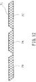
- the ceiling installation type air conditioner of the seventh embodiment will be described with reference to Fig. 11 and Fig. 12 .
- the same reference signs are assigned to the components of the seventh embodiment that are the same as the components shown in Fig. 1 to Fig. 10 .
- Fig. 11 is a side cross-sectional view illustrating the heat exchanger of the ceiling installation type air conditioner according to the seventh embodiment.
- the heat exchanger 7 of the embodiment is an integrally molded product, and the first to third heat exchange sections 7A, 7B, and 7C are integrally formed. Instead of being formed by combining separate heat exchange sections, the heat exchanger 7 of the embodiment has a substantially trapezoidal shape as one piece.
- the heat exchanger 7 is integrally formed as one piece instead of combining the first to third heat exchange sections 7A, 7B, and 7C with separate components, components for fixing respective heat exchange sections can be omitted and thus the heat exchanger can reduce the number of components, and thus the heat exchanger can improve in manufacturability.
- the fins 71 before a bending process of the heat exchanger 7 of the embodiment is linear, and the first to third heat exchange sections 7A, 7B, and 7C may be formed by bending two points thereof.
- the fins 71 of the heat exchanger 7 are first formed into such a shape that a total length of the fin 71 is the combined length of the first to third heat exchange sections 7A, 7B, and 7C.
- the boundary between the first and second heat exchange sections 7A and 7B i.e., the joint of the first and second heat exchange sections
- the boundary between the first and third heat exchange sections 7A and 7C is cut out according to the bending margin.
- the respective portions corresponding to the first and third heat exchanging portions 7A and 7C have a trapezoidal shape, and the portion corresponding to the second the heat exchanger portion 7B has a parallelogram shape.
- the heat exchanger 7 is formed in a substantially trapezoidal shape.
- the heat exchanger 7 By forming the heat exchanger 7 in this manner, its manufacturability can be improved. Specifically, it is possible to make favorable the yield of the fins material and to share pipe expanding equipment of a linear heat exchanger. Thus, it is possible to suppress capital investment and reduce cost by reducing materials.
- the ceiling installation type air conditioner of the eighth embodiment will be described with reference to Fig. 13 .
- the same reference signs are assigned to the components of the eighth embodiment that are the same as the components shown in Fig. 1 to Fig. 12 .
- Fig. 13 is a side cross-sectional view illustrating the heat exchanger of the ceiling installation type air conditioner according to the eighth embodiment.
- the inclination angle ⁇ 1 of the second heat exchange section 7B disposed at the upper portion of the heat exchange chamber 4 of the embodiment is smaller than the inclination angle ⁇ 2 of the third heat exchange section 7C disposed at the lower part of the heat exchange chamber 4. That is, angle difference is provided between the inclination angle ⁇ 1 and the inclination angle ⁇ 2.
- the second heat exchange section 7B is inclined slightly downward as being separated from the blower 5, and the third heat exchange section 7C is inclined slightly upward as being separated from the blower 5. It is possible to reduce the ventilation resistance of the third heat exchange section 7C positioned at the lower side where wind is relatively hard to reach, and thereby air volume can be improved by providing the angle difference between the inclination angles ⁇ 1 and ⁇ 2, it.
- the ceiling installation type air conditioner of the ninth embodiment will be described with reference to Fig. 14 .
- the same reference signs are assigned to the components of the ninth embodiment that are the same as the components shown in Fig. 1 to Fig. 13 .
- Fig. 14 is a side cross-sectional view illustrating the heat exchanger of the ceiling installation type air conditioner according to the ninth embodiment.
- the first heat exchange section 7A is positioned at the center of the heat exchange chamber 4 of the embodiment and is inclined such that its upper end portion is positioned on the windward side of its lower end portion.
- the second heat exchange section 7B is positioned at the upper portion of the heat exchange chamber 4.
- the second heat exchange section 7B is disposed such that the front end portion of the second heat exchange section 7B and the upper end portion of the first heat exchange section 7A are continuous.
- the third heat exchange section 7C is positioned at the lower portion of the heat exchange chamber 4.
- the third heat exchange section 7C is disposed such that the front end portion of the third heat exchange section 7C and the lower end portion of the first heat exchange section 7A are continuous.
- first and second heat exchange sections 7A and 7B are disposed such that the long sides 71L of the fins 71 of the first heat exchange section 7A on the side of the blower chamber 3 are in contact with the short sides 71S of the fins 71 of the second heat exchange section 7B on the side of the air outlet 28 without any gap.
- first and third heat exchange sections 7A and 7C are disposed such that the short sides 71S on the lower side of the fins 71 of the first heat exchange section 7A are in contact with the short sides 71S of the fins 71 of the third heat exchange section 7C on the side of on the air outlet 28 without any gap.
- the shape of the fins 71 of the first heat exchange section 7A is line-symmetrical with the shape of the fins 71 of the third heat exchange section 7C.
- the length dimension of the long side 71L of each of the fins 71 is shorter than that of the other heat exchange sections.
- the second heat exchange section 7B that is harder to wind than the first heat exchange section 7A has fewer heat transfer tubes than the other heat exchange sections. For instance, when the number of stages (rows) of the heat transfer tubes of each of the first and third heat exchange sections 7A and 7C is ten, the number of stages (rows) of the second heat exchange section 7B is eight.
- the first heat exchange section 7A positioned at the center portion is inclined with respect to the blowout ports 55a and 55b and the partition plate 26 so as to be susceptible to wind.
- the heat exchanger 7 is more likely to receive air, and air volume and wind speed of the air passing through the heat exchanger 7 can be improved by tilting the first heat exchange section 7A.
- the wind speed distribution improves and the blowing performance is enhanced by improving the air volume and the wind speed.
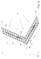
- the housing 20 accommodating the blower 5 and the heat exchanger 7 is hung from the beam of the building via four hanger bolts HB in each of the above embodiments, for instance.
- four metallic hangers 29 are fixed to the top plate 21 of the housing 20.
- the respective metallic hangers 29 horizontally protrude from the four corner portions of the top plate 21 toward the four sides of the housing 20, and the respective lower end portions of the hanger bolts HB are connected to the metallic hangers 29.
- the first heat exchange section 7A is disposed so as to stand inside the heat exchange chamber 4 in each of the above-described embodiments, the first heat exchange section 7A may be inclined and disposed as a convex shape protruding toward the air outlet 28, for instance.
- the short sides 71S on the lower side of the fins 71 of the first heat exchange section 7A and the short sides 71S of the fins 71 of the third heat exchange section 7C on the side of the air outlet 28 are closest to the air outlet 28.
- the ceiling installation type air conditioner of the tenth embodiment will be described with reference to Fig. 15 to Fig. 17 .
- the same reference signs are assigned to the components of the tenth embodiment that are the same as the components shown in Fig. 1 to Fig. 14 .
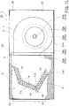
- Fig. 15 is a schematic side cross-sectional view of the ceiling installation type air conditioner according to the tenth embodiment.
- the heat exchanger 7 and the drain pan 8 of the embodiment are housed in the heat exchange chamber 4 of the housing 20.
- the heat exchanger 7 extends in the width direction of the housing 20.
- the drain pan 8 is a heat insulating material such as expanded polystyrene.
- the drain pan 8 supports the heat exchanger 7 from below so as to receive the drain water dripping from the heat exchanger 7, and cooperates with the heat insulating material 9 to surround the heat exchanger 7. Further, the lower surface of the drain pan 8 is covered with the first bottom plate 23a.
- the heat exchanger 7 of the embodiment includes the first heat exchange section 7A, the second heat exchange section 7B, and the third heat exchange section 7C. These first to third heat exchange sections 7A, 7B, and 7C are independent components and are three-dimensionally combined into a predetermined steric shape.
- Each of the first to third heat exchange sections 7A, 7B, and 7C includes plural elongated plate-shaped fins 71 and plural heat transfer tubes 72 through which the refrigerant flows.
- the fins 71 are arranged at intervals in the width direction of the housing 20.
- the heat transfer tubes 72 are integrated with the fins 71 by continuously penetrating the adjacent fins 71.
- the second heat exchange section 7B is positioned at the upper portion of the heat exchange chamber 4.
- the second heat exchange section 7B extends in the depth direction of the housing 20 from the partition plate 26 toward the air outlet 28 of the housing 20.
- the second heat exchange section 7B is inclined slightly downward as it approaches the air outlet 28.
- the third heat exchange section 7C is positioned at the bottom of the heat exchange chamber 4, and is separated from the second heat exchange section 7B in the height direction of the housing 20.
- the third heat exchange section 7C extends in the depth direction of the housing 20 from the partition plate 26 toward the air outlet 28 of the housing 20.
- the third heat exchange section 7C is inclined slightly upward as it approaches the air outlet 28. Therefore, each of the second heat exchange section 7B and the third heat exchange section 7C has one end that is positioned closer to the air outlet 28 than the partition plate 26.
- the first heat exchange section 7A is interposed between one end of the second heat exchange section 7B and one end of the third heat exchange section 7C.
- the first heat exchange section 7A stands so as to face the partition plate 26, and is inclined such that the portion thereof closer to one end of the second heat exchange section 7B is closer to the partition plate 26.
- the first heat exchange section 7A is inclined such that one end portion on the side of the third heat exchange section 7C is the closest to the air outlet 28 and another end portion on the side of the second heat exchange section 7B is the farthest from the air outlet 28.
- the first to third heat exchange sections 7A, 7B, and 7C are combined in a shape that is more opened towards the partition plate 26 when viewing the housing 20 from the side.
- the short side 71S of the fins 71 of the third heat exchange section 7C on the side of the air outlet 28 is the closest to the air outlet 28.
- the end portion PC of the third heat exchange section 7C is the corner portion of the short side 71S and the long side 71L on the side of the air outlet 28.
- the third heat exchange section 7C is arranged such that the end portion PC more protrudes towards the air outlet 28 than the end PA that is the corner of the short side 71S and the long side 71L of the first heat exchange section 7A on the air outlet 28 side (i.e., the tip of the end portion PC does not match the tip of the end portion PA).
- step) ⁇ that protrudes toward the air outlet 28 by a predetermined length 1 from the tip of the long side 71L of the first heat exchange section 7A on the side of the air outlet 28.
- the first and third heat exchange sections 7A and 7C are arranged such that the distance LA is longer than the distance LC.
- the shortest distance LA in the first heat exchange section 7A is the distance between the end portion PA and the air outlet 28, since the end portion PA that is the corner of the short side 71S and the long side 71L on the side of the air outlet 28 is the point closest to the air outlet 28.
- the shortest distance LC in the third heat exchange section 7C is the distance between the end portion PC and the air outlet 28, since the end portion PC which is the corner of the short side 71S and the long side 71L on the side of the air outlet 28 is the point closest to the air outlet 28.
- condensed water Y is generated when wind X sent from the blower 5 passes between the fins 71 of the heat exchanger 7 (i.e., passes through the ventilation passages 74) during cooling operation.
- This condensed water Y is generated in each of the first to third heat exchange sections 7A, 7B, and 7C.
- the condensed water Y generated in the first heat exchange section 7A flows down toward the third heat exchange section 7C positioned at the lower part along the fins 71.
- a contact surface ⁇ of the first heat exchange section 7A and the third heat exchange section 7C the ends of the fins 71 of the respective heat exchanging sections are closely packed, and thus the condensed water Y tends to stay.
- the contact surface ⁇ receives the wind X from the blower 5
- the accumulated condensed water Y may be pushed out in the ventilation direction and sometimes be flied out of the air conditioner from the air outlet 28.
- the end portion of the third heat exchange section 7C is arranged so as to protrude toward the air outlet 28 more than the end portion PA of the first heat exchange section 7A, and the protruding portion ⁇ is provided because the end portion PC is not aligned with the end portion PA.
- the condensed water Y staying on the contact surface ⁇ of the first heat exchange section 7A and the third heat exchange section 7C once stays in the protruding portion ⁇ in the course of being sent to the side of the air outlet 28 by the wind X, and flows down to the third the heat exchange section 7C.
- the condensed water Y is guided to the drain pan 8 without being scattered by the wind X.
- the condensed water Y is likely to splash by the wind X from the end portions PA and PC that are the most protruding tip portions on the side of the air outlet 28 in the heat exchanger 7.
- the most protruding tip portion of the heat exchanger 7 is not the end portion PA in the embodiment by providing the protruding portion ⁇ which is a stepped portion.
- the condensed water Y flowing down from the first heat exchange section 7A does not directly flow to the end portion PC of the third heat exchange section 7C but once stays in the protrusion portion ⁇ by the surface tension before reaching the end portion PC of the third heat exchange section 7C.
- the condensed water Y easily flows down to the third heat exchange section 7C, and becomes unlikely to scatter.
- the condensed water Y that has stagnated in the contact surface ⁇ of the first and third heat exchange sections 7A and 7C can be recovered in the third heat exchange section 7C, and thus scattering of the condensed water Y by the wind X can be suppressed.
- a gap may be generated on the contact surface ⁇ of the first and third heat exchange sections 7A and 7C due to causes such as manufacturing error and aging deformation.
- the gap is generated on the contact surface ⁇ of the first and third heat exchange sections 7A and 7C, it is conceivable that a lot of condensed water Y stays in this gap due to the surface tension.
- scattering of such condensed water Y can be suppressed.
- the ceiling installation type air conditioner of at least one of the embodiments as described above it is possible to provide a ceiling installation type air conditioner that is compact and has high heat exchange efficiency.
Landscapes
- Engineering & Computer Science (AREA)
- Mechanical Engineering (AREA)
- General Engineering & Computer Science (AREA)
- Physics & Mathematics (AREA)
- Chemical & Material Sciences (AREA)
- Combustion & Propulsion (AREA)
- Thermal Sciences (AREA)
- Geometry (AREA)
- Air Filters, Heat-Exchange Apparatuses, And Housings Of Air-Conditioning Units (AREA)
- Details Of Heat-Exchange And Heat-Transfer (AREA)
- Heat-Exchange Devices With Radiators And Conduit Assemblies (AREA)
Description
- Embodiments according to the present invention relate to a ceiling installation type air conditioner comprising a heat exchanger.
- An indoor unit of a ceiling installation type air conditioner (i.e., ceiling-installed air conditioner) is installed in ceiling space such that the indoor unit is suspended from the characteristics of a beam provided on an attic or is buried in the attic. The inside of the indoor unit is partitioned with a partition plate into a heat exchange chamber and a blower chamber. A heat exchanger is disposed in the heat exchange chamber, and a blower for sending air to the heat exchanger is disposed in the blower chamber.
- The heat exchanger includes plural heat transfer tubes through which refrigerant flows and plural fins that are thermally connected to the heat transfer tubes. The heat exchanger is in the form of a flat plate as a whole. Further, the heat exchanger is accommodated in the heat exchange chamber in the state of being largely inclined with respect to the blower in order to efficiently receive the air sent from the blower and to minimize the height dimension of the indoor unit.
-
- Patent Document 1: Japanese Unexamined Patent Application Publication No.
2006-343043 - Since the heat exchanger in the form of a flat plate is disposed in the heat exchange chamber so as to be inclined in the conventional air conditioner, much wasted space is inevitably generated inside the heat exchange chamber, which causes increase in depth dimension. The outer dimension of the heat exchange chamber increases in proportion to capacity. Thus, larger space is required inside the heat exchange chamber as capacity of the heat exchanger increases. These factors hinder downsizing of the indoor unit.
- Further, since the heat exchanger in the form of a flat plate is disposed in the heat exchange chamber so as to be inclined in the conventional air conditioner, the distance from the blower greatly differs between the front end portion and the rear end portion of the heat exchanger in the conventional air conditioner. Thus, depending on a location of the heat exchanger, the volume of air passing through the heat exchanger easily varies. Variation in volume of the air passing through the heat exchanger degrades performance of the heat exchanger. Hence, the conventional air conditioner leaves room for improvement in order to fully demonstrate the performance of the heat exchanger.
- To achieve the above object, an aspect of the present invention provides a ceiling-mounted air conditioner that is compact and has high heat exchange efficiency.
- To achieve the above object, the present invention provides a ceiling installation type air conditioner according to
claim 1. - It may be desired that the plate-shaped fins has a substantially parallelogram shape.
- It may be desired that a long side of the plate-shaped fins of the first heat exchange section on the blower chamber side is in contact with a short side of the plate-shaped fins of the second heat exchange section on the air outlet side without any gap, and a short side of the plate-shaped fins of the first heat exchange section on the air outlet side is in contact with a short side of the plate-shaped fins of the third heat exchange section on the air outlet side without any gap.
- It may be desired that the first heat exchange section is closest to the air outlet out of the first heat exchange section, the second heat exchange section, and the third heat exchange section, and number of the heat transfer tubes provided for the first heat exchange section is larger than the number of the heat transfer tubes provided for each of the second heat exchange section and the third heat exchange section.
- It may be desired that an interval at which the plate-shaped fins of the first heat exchange sections are arranged is narrower than an interval at which the plate- shaped fins of each of the second heat exchange section and the third heat exchange section are arranged.
- It may be desired that slits are provided only in the plate-shaped fins of the first heat exchange section.
- It may be desired that a pipe diameter of the heat transfer tubes of the first heat exchange section is larger than a pipe diameter of the heat transfer tubes of the second heat exchange section and the third heat exchange section.
- It may be desired that the first heat exchange section, the second heat exchange section, and the third heat exchange section are integrally formed.
- It may be desired that the second heat exchange section is disposed at an upper portion of the heat exchange chamber, the third heat exchange section is disposed at a lower portion of the heat exchange chamber, and angle difference is provided in such a manner that an inclination angle of the second heat exchange section is smaller than an inclination angle of the third heat exchange section.
- According to the invention, the first heat exchange section is inclined in such a manner that an upper end portion of the first heat exchange section is positioned on a windward side of a lower end portion of the first heat exchange section.
- It may be desired that an end portion of a short side of the plate-shaped fins of the third heat exchange section on a side of the air outlet is protruded toward the air outlet more than an end portion of a short side positioned at a lower portion of the plate-shaped fins of the first heat exchange section.
- It may be desired that a shortest distance between the air outlet and an end portion on a side of the air outlet of a short side positioned at a lower portion of the plate-shaped fins of the first heat exchange section is longer than a shortest distance between the air outlet and an end portion on a side of the air outlet of a short side positioned at a lower portion of the plate-shaped fins of the third heat exchange section.
- Several embodiments are shown in the drawings. However, only the tenth embodiment is in accordance with the invention.
-
-
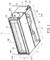
Fig. 1 is a perspective view of a ceiling installation type air conditioner according to a first embodiment. -
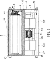
Fig. 2 is an exploded bottom view illustrating the inside of the ceiling installation type air conditioner according to the first embodiment. -
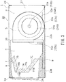
Fig. 3 is a schematic side cross-sectional view of the ceiling installation type air conditioner according to the first embodiment. -
Fig. 4 is an enlarged cross-sectional view illustrating a part of fins and heat transfer tubes constituting a heat exchanger of the ceiling installation type air conditioner according to the first embodiment. -
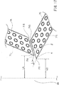
Fig. 5 is a schematic view illustrating a shape of each fin constituting the heat exchanger of the ceiling installation type air conditioner according to the first embodiment. -
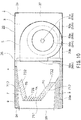
Fig. 6 is a schematic side cross-sectional view of the ceiling installation type air conditioner according to a second embodiment. -
Fig. 7 is a view illustrating shapes of fins constituting the heat exchanger of the ceiling installation type air conditioner according to a third embodiment. -
Fig. 8 is a schematic side cross-sectional view of the ceiling installation type air conditioner according to the third embodiment. -
Fig. 9 is a view illustrating shapes of fins constituting the heat exchanger of the ceiling installation type air conditioner according to a fifth embodiment. -
Fig. 10 is a schematic side cross-sectional view of the ceiling installation type air conditioner according to a sixth embodiment. -
Fig. 11 is a schematic side cross-sectional view of the ceiling installation type air conditioner according to a seventh embodiment. -
Fig. 12 is a view illustrating shapes of fins constituting the heat exchanger of the ceiling installation type air conditioner according to the seventh embodiment. -
Fig. 13 is a schematic side cross-sectional view of the ceiling installation type air conditioner according to an eighth embodiment. -
Fig. 14 is a schematic side cross-sectional view of the ceiling installation type air conditioner according to a ninth embodiment. -
Fig. 15 is a schematic side cross-sectional view of the ceiling installation type air conditioner according to a tenth embodiment. -
Fig. 16 is a schematic diagram illustrating configuration of the heat exchanger of the ceiling installation type air conditioner according to the tenth embodiment. -
Fig. 17 is an enlarged schematic view illustrating configuration of the heat exchanger of the ceiling installation type air conditioner according to the tenth embodiment. - Hereinbelow, embodiments will be described. Only the tenth embodiment is in accordance with the invention.
- The ceiling installation type air conditioner of the first embodiment will be described with by referring to
Fig. 1 to Fig. 5 . -
Fig. 1 illustrates the ceiling installationtype air conditioner 1 of the embodiment. Anindoor unit 2 of the ceiling installationtype air conditioner 1 is installed, e.g., on an attic of a building. The attic of the embodiment is defined as ceiling space between a ceiling plate and a beam of the building. - The
indoor unit 2 is formed in the shape of a rectangular flat box having a depth dimension D, a width dimension W, and a height dimension H. In addition, theindoor unit 2 includes ametallic housing 20. Thehousing 20 is an outer periphery of theindoor unit 2. Thehousing 20 includes atop plate 21, afirst side plate 22a, asecond side plate 22b, a firstbottom plate 23a, asecond bottom plate 23b, afront frame 24, arear frame 25, and apartition plate 26. - As shown in
Fig. 2 andFig. 3 , thepartition plate 26 of the ceiling installationtype air conditioner 1 according to the embodiment partitions the interior of thehousing 20 into two chambers that are ablower chamber 3 and aheat exchange chamber 4. - The
blower chamber 3 has anair inlet 27 formed in therear frame 25. Ablower 5 is accommodated in theblower chamber 3. As shown inFig. 2 andFig. 3 , theblower 5 includes afan motor 51,fan cases multi-blade fans fan cases Respective suction ports fan cases partition plate 26 is provided withblowout ports - The
fan motor 51 includes tworotating shafts multi-blade fans rotating shafts - The
heat exchange chamber 4 includes amachine room 6 and anair outlet 28 formed in thefront frame 24. Themachine room 6 is partitioned from theheat exchange chamber 4 with a machine-room partition plate 61, and accommodates a drain pump and a refrigerant distributor. - The
blower chamber 3 and theheat exchange chamber 4 are connected to each other via theblower 5. Specifically, both are spatially connected with each other such that air in theblower chamber 3 can flow into theheat exchange chamber 4 through theblower 5. - In addition, a
heat exchanger 7 and adrain pan 8 are disposed in theheat exchange chamber 4 as shown inFig. 3 . In other words, theheat exchanger 7 and thedrain pan 8 are housed in theheat exchange chamber 4 of thehousing 20. Theheat exchanger 7 extends in the width direction of the indoor unit 2 (i.e., in the width direction of the housing 20), and is interposed between the machine-room partition plate 61 and theside plate 22a. - As shown in
Fig. 3 , thedrain pan 8 is disposed below theheat exchanger 7. Thedrain pan 8 is a heat insulating material such as expanded polystyrene. Thedrain pan 8 supports theheat exchanger 7 from the lower side, and receives drain water dripping from theheat exchanger 7. The lower surface of thedrain pan 8 is covered with thefirst bottom plate 23a. In addition, thedrain pan 8 cooperates with aheat insulating material 9 to surround theheat exchanger 7. Theheat insulating material 9 is disposed above theheat exchanger 7, and is provided on the inner surface of thetop plate 21 and in theheat exchange chamber 4. - The
heat exchanger 7 of the embodiment includes a firstheat exchange section 7A, a secondheat exchange section 7B, and a thirdheat exchanging portion 7C. The firstheat exchange section 7A, the secondheat exchange section 7B, and the thirdheat exchange section 7C are disposed so as to protrude toward theair outlet 28 in a convex shape. - The first
heat exchange section 7A stands inside theheat exchange chamber 4 so as to face substantially parallel to thepartition plate 26 and theblowout ports blower 5. Out of the firstheat exchange section 7A, the secondheat exchange section 7B, and the thirdheat exchange section 7C, the firstheat exchange section 7A is the closest to theair outlet 28 in the embodiment. - The second
heat exchange section 7B is located at the upper portion of theheat exchange chamber 4, and extends in the depth direction of theindoor unit 2 so as to be separated away from theblower 5 in a cross-sectional view. In addition, the secondheat exchange section 7B is inclined slightly downward as separating from theblower 5. In other words, the secondheat exchange section 7B is inclined slightly downward as it approaches theair outlet 28. The front end (i.e., the side of the air outlet 28) of the secondheat exchange section 7B is spatially continuous with the upper end of the firstheat exchange section 7A. - The third
heat exchange section 7C is positioned at the lower portion of theheat exchange chamber 4, and extends in the depth direction of theindoor unit 2 so as to be separated away from theblower 5 in a cross-sectional view. In addition, the thirdheat exchange section 7C is inclined slightly upward as separating from theblower 5. In other words, the thirdheat exchange section 7C is inclined slightly upward as it approaches theair outlet 28. The front end (i.e., the side of the air outlet 28) of the thirdheat exchange section 7C is spatially continuous with the lower end of the firstheat exchange section 7A. - In other words, the
heat exchanger 7 includes: the firstheat exchange section 7A that stands so as to face theblowout ports partition plate 26; the secondheat exchange section 7B that extends obliquely upward from the upper end of the firstheat exchange section 7A toward theblower 5; and the thirdheat exchange section 7C that extends obliquely downward from the lower end of the firstheat exchange section 7A toward theblower 5. - Thus, when the
indoor unit 2 is viewed from the side, the first to thirdheat exchange sections heat exchanger 7 is disposed so as to have a convex shape protruding toward the leeward side with respect to wind sent from theblower chamber 3, and is disposed so as to have a substantially concave shape recessed toward the windward side. - In addition, it can be said that the first to third
heat exchange sections indoor unit 2 is viewed from the side. The firstheat exchange section 7A is disposed at the portion (side) corresponding to the smaller base and the second and thirdheat exchange sections - As shown in
Fig. 4 , theheat exchanger 7 of the ceiling installationtype air conditioner 1 according to the embodiment is a fin-tube type heat exchanger that is a combination of plate-like fins and heat transfer tubes. Each of the first to thirdheat exchange sections fins 71 and pluralheat transfer tubes 72 through which a refrigerant flows. - As shown in
Fig. 5 , thefins 71 of the ceiling installationtype air conditioner 1 according to the embodiment are, e.g., a quadrilateral plate made of aluminum and has a pair oflong sides 71L and a pair ofshort sides 71S. Thelong sides 71L are parallel to each other. Theshort sides 71S are parallel to each other, and extend obliquely so as to intersect thelong sides 71L. In other words, thefins 71 have a parallelogram shape in which two pairs of opposite sides are parallel to each other. - Further, the
fins 71 are provided with plural engagement holes 73. The engagement holes 73 have a cylindrical flange portion that is pierced by, e.g., applying a burring process to thefins 71 and rises from thefins 71. For instance, the engagement holes 73 are arranged in eight rows in the direction along thelong sides 71L of thefins 71 and in three columns in the direction along theshort sides 71S of thefins 71. - As shown in
Fig. 4 , thefins 71 are arranged in one row at intervals in the width direction W of theindoor unit 2. In other words, thefins 71 are arranged at intervals in the width direction of thehousing 20. The respective tips of the flange portions rising from eachfin 71 butts against theadjacent fin 71 so as to coaxially match the engagement holes 73 of theadjacent fin 71. Thus,ventilation passages 74 through which air flows are provided between theadjacent fins 71. - The
heat transfer tubes 72 are, e.g., copper tubes that are excellent in thermal conductivity. Each of theheat transfer tubes 72 includes a straight pipe portion extending straight in the width direction of theindoor unit 2 and a bent pipe portion bent substantially in a U shape. The respective straight pipe portions of theheat transfer tubes 72 continuously penetrate the engagement holes 73 of thefins 71. As a result, theheat transfer tubes 72 are thermally connected to thefins 71. Theheat transfer tubes 72 are integrated with thefins 71 by continuously penetrating theadjacent fins 71. - In addition, as shown in
Fig. 3 , one of theshort sides 71S of eachfin 71 of the firstheat exchange section 7A and theshort side 71S of eachfin 71 of the secondheat exchange section 7B on the side of theair outlet 28 are disposed so as to be in contact with each other without any gap in the first embodiment. - Further, the
long side 71L of thefins 71 of the firstheat exchange section 7A on the side of theblower chamber 3 and theshort side 71S of the thirdheat exchange section 7C on the side of theair outlet 28 are arranged so as to be in contact with each other without any gap in the embodiment. Alternatively, the othershort side 71S of thefin 71 of the firstheat exchange section 7A and thelong side 71L of the thirdheat exchange section 7C on the side of theblower chamber 3 are arranged so as to be in contact with each other without any gap. - When the
fan motor 51 rotates themulti-blade fans multi-blade fans blower chamber 3 from thesuction ports fan cases blowout ports fan cases - Thus, the air in the building room is sucked into the
blower chamber 3 from theair inlet 27 of thehousing 20 via a non-illustrated duct or a suction grill of the ceiling board. The air sucked into theblower chamber 3 is blown out from theblowout ports heat exchanger 7 via thefans - Since the first
heat exchange section 7A of theheat exchanger 7 stands so as to face theblowout ports heat exchange chamber 4, a major portion of the air blown out from theblowout ports heat exchange chamber 4 flows through the interval between thefins 71 of the firstheat exchange section 7A (i.e., through the ventilation passages 74). - The rest of the air blown out toward the
heat exchange chamber 4 flows through the interval between thefins 71 of the secondheat exchange section 7B extending obliquely upward from the upper end of the firstheat exchange section 7A towards the blower 5 (i.e., through the ventilation passages 74), and further flows through the interval between thefins 71 of the thirdheat exchange section 7C extending obliquely downward from the lower end of the firstheat exchange section 7A toward the blower 5 (i.e., through the ventilation passages 74). - As a result, the
heat exchanger 7 converts the inhaled air into cold or warm air by heat exchange between the air blown out from theblowout ports heat transfer tubes 72. The air subjected to the heat exchange is delivered from theair outlet 28 to the inside of the room through a blow duct. - The
heat exchanger 7 of the embodiment combines the first to thirdheat exchange sections heat exchanger 7 along the depth direction of theheat exchange chamber 4 can be shortened as compared with the case where the conventional straight heat exchanger is disposed so as to be inclined in the heat exchange chamber. - Additionally, the first
heat exchange section 7A stands inside theheat exchange chamber 4 in the embodiment. Thus, the dimension of theheat exchanger 7 along the depth direction of theheat exchange chamber 4 in the embodiment can be shortened by the difference between the distance from the open ends of theblowout ports heat exchange section 7A and the distance from the open ends of theblowout ports heat exchange section 7B, as compared with the case where the conventional straight heat exchanger is disposed so as to be inclined in the heat exchange chamber. As a result, the depth dimension of theheat exchange chamber 4 can be kept small, and thehousing 20 of theindoor unit 2 can be made compact. - Further, the heat capacity of the
heat exchanger 7 can be sufficiently improved by bending theheat exchanger 7 in the embodiment. Thus, in the embodiment, theheat exchanger 7 having a large capacity can be disposed in the compactheat exchange chamber 4, and theindoor unit 2 having excellent heat exchange performance can be provided. - Moreover, as the
housing 20 is made more compact, thehousing 20 can be reduced in weight in the embodiment. Thus, the workability at the time of installing theindoor unit 2 in ceiling space is improved. Furthermore, since thehousing 20 becomes smaller, it is possible to obtain an inexpensiveindoor unit 2 by reducing manufacturing cost of thehousing 20. - In addition, since the first
heat exchange section 7A stands inside theheat exchange chamber 4 in the embodiment, the difference between the distance from the open ends of the blowout ports 54 to the front end of the firstheat exchange section 7A and the distance from the open ends of the blowout ports 54 to the rear end of the secondheat exchange section 7B is smaller than in the case where the conventional straight heat exchanger is disposed so as to be inclined inside the heat exchange chamber. Accordingly, it is possible to blow air substantially uniformly to theheat exchanger 7, and thus satisfactory heat exchange performance can be obtained. - The second
heat exchange section 7B of the embodiment is inclined upward from the upper end of the firstheat exchange section 7A toward the blower chamber side, and the thirdheat exchange section 7C is inclined downward from the lower end of the firstheat exchange section 7A toward the blower chamber side. Hence, the secondheat exchange section 7B and the thirdheat exchange section 7C become susceptible to air, and thus air volume of the air passing through the upper portion and the lower portion of theheat exchanger 7 can be improved. Accordingly, theheat exchanger 7 having excellent heat exchange performance can be obtained. - Further, in the embodiment, a gap causing air leakage is excluded from the joint of (i.e., boundary between) the first and second
heat exchange sections heat exchange sections heat exchange sections heat exchanger 7. - Moreover, it is possible to reduce the number of members that prevent air from leaking without being subjected to heat exchange from the joints in the embodiment.
- Thus, according to the embodiment, it is possible to provide a ceiling installation type air conditioner that is compact and has high heat exchange efficiency.
- The ceiling installation type air conditioner of the second embodiment will be described with reference to
Fig. 6 . The same reference signs are assigned to the components of the second embodiment that are the same as the components shown inFig. 1 to Fig. 5 . -
Fig. 6 is a side cross-sectional view illustrating the heat exchanger of the ceiling installation type air conditioner according to the second embodiment. As shown inFig. 6 , theheat transfer tubes 72 are disposed such that the number of theheat transfer tubes 72 of the firstheat exchange section 7A is larger than the number of theheat transfer tubes 72 of each of theheat exchange sections - The first
heat exchange section 7A of the embodiment stands inside theheat exchange chamber 4 so as to face thepartition plate 26 and theblowout ports blower 5, and thus receives much wind sent out from theblower 5. - A total of 24 engagement holes 73 are provided in a
fins 711 of the firstheat exchange section 7A, and are arranged in eight rows along the long side direction of thefins 711 and in three columns along the short side direction of thefins 711. A total of 20 engagement holes 73 are provided in afins 712 of the second and thirdheat exchange sections fins 712 and in two columns along the short side direction of thefins 712. In other words, the number of the heat transfer tubes in the firstheat exchange section 7A is larger than that in each of the second and thirdheat exchange sections blower 5. - In the embodiment as described above, the major portion of the total air sent to
heat exchanger 7 is distributed to the firstheat exchange section 7A, and this firstheat exchange section 7A performs heat exchange more than the other heat exchange sections. Thus, it is possible to perform heat exchange in a well-balanced manner and to improve heat exchange performance. - According to the second embodiment, it is possible to provide a ceiling installation type air conditioner with high heat exchange efficiency.
- The ceiling installation type air conditioner of the third embodiment will be described with reference to
Fig. 7 andFig. 8 . The same reference signs are assigned to the components of the third embodiment that are the same as the components shown inFig. 1 to Fig. 6 . -
Fig. 7 is a schematic view illustrating the shape of thefins 71 of the heat exchanger of the ceiling installation type air conditioner according to the third embodiment.Fig. 8 is a side cross-sectional view illustrating the heat exchanger of the ceiling installation type air conditioner according to the third embodiment. - In the ceiling installation
type air conditioner 1 of the embodiment as shown inFig. 7 andFig. 8 , thefins 711 of the firstheat exchange section 7A are line-symmetrical with thefins 712 of the second and thirdheat exchange sections - Since the
fins 711 and thefins 712 are line-symmetrical in the ceiling installationtype air conditioner 1 of the embodiment, the fins can be made common between respective sections of theheat exchanger 7. Thus, the ceiling installationtype air conditioner 1 of the embodiment can improve manufacturability and reduce cost. - According to the embodiment, it is possible to provide a compact ceiling installation type air conditioner with improved manufacturability and high heat exchange efficiency.
- The ceiling installation type air conditioner of the embodiment will be described. The same reference signs are assigned to the components of the fourth embodiment that are the same as the components shown in
Fig. 1 to Fig. 8 . - Hereinafter, a fin pitch of the embodiment is defined as an interval by which the
fins 711 of the firstheat exchange section 7A or thefins 712 of the second and thirdheat exchange sections housing 20. The fin pitch of thefins 711 is narrower than the fin pitch of thefins 712. - In other words, the fin pitch is each
ventilation passage 74. The narrower the fin pitch of thefins - The first
heat exchange section 7A is arranged to receive more wind sent from theblower 5 so that the major portion of the total air sent to theheat exchanger 7 is distributed to the firstheat exchange section 7A. The fin pitch of thefins 711 of the firstheat exchange section 7A is narrower than the fin pitch of thefins 712 of each of the second and thirdheat exchange sections heat exchange sections heat exchange section 7A, and thus it is possible to adjust air volume. - Thus, in the embodiment, it is possible to improve heat exchange performance by adjusting air volume distributed to the first
heat exchange section 7A, the secondheat exchange section 7B, and the thirdheat exchange section 7C. - According to the embodiment, it is possible to provide a ceiling installation type air conditioner with high heat exchange efficiency.
- The ceiling installation type air conditioner of the fifth embodiment will be described with reference to
Fig. 9 . InFig. 9 of the embodiment, the same reference signs are assigned to the same components as the components shown inFig. 1 to Fig. 8 . - In the embodiment as shown in
Fig. 9 , slits 81 are provided in thefins 711 of the firstheat exchange section 7A. Generally, by forming theslits 81 that become cuts or narrow gaps in aluminum fins, heat transfer performance is enhanced and air resistance is also increased. - The
slits 81 are provided in thefins 711 of the firstheat exchange section 7A and theslits 81 are not provided in thefins 712 of the second and thirdheat exchange sections fins 711 of the firstheat exchange section 7A to which the major portion of air volume is distributed. - At the same time, it is possible to send more wind to the second and third
heat exchange sections fins 711 of the firstheat exchange section 7A. - According to the embodiment, it is possible to provide a ceiling installation type air conditioner with high heat exchange efficiency.
- The ceiling installation type air conditioner of the sixth embodiment will be described with reference to
Fig. 10 . The same reference signs are assigned to the components of the embodiment that are the same as the components shown inFig. 1 to Fig. 9 . -
Fig. 10 is a side cross-sectional view illustrating the heat exchanger of the ceiling installation type air conditioner according to the sixth embodiment. - As shown in
Fig. 10 , the tube diameter of eachheat transfer tube 731 of the firstheat exchange section 7A of the embodiment is larger than the tube diameter of eachheat transfer tube 732 of the second and thirdheat exchange sections - In the embodiment, it is possible to perform heat exchange in a well-balanced manner and enhance heat exchange performance by improving the heat transfer performance of the first
heat exchange section 7A to which the major portion of air volume is distributed. - According to the embodiment, it is possible to provide a ceiling installation type air conditioner with high heat exchange efficiency.
- The ceiling installation type air conditioner of the seventh embodiment will be described with reference to
Fig. 11 andFig. 12 . The same reference signs are assigned to the components of the seventh embodiment that are the same as the components shown inFig. 1 to Fig. 10 . -
Fig. 11 is a side cross-sectional view illustrating the heat exchanger of the ceiling installation type air conditioner according to the seventh embodiment. - As shown in
Fig. 11 , theheat exchanger 7 of the embodiment is an integrally molded product, and the first to thirdheat exchange sections heat exchanger 7 of the embodiment has a substantially trapezoidal shape as one piece. - Since the
heat exchanger 7 is integrally formed as one piece instead of combining the first to thirdheat exchange sections - Further, as shown in
FIG. 12 , thefins 71 before a bending process of theheat exchanger 7 of the embodiment is linear, and the first to thirdheat exchange sections - For instance, as a manufacturing process, the
fins 71 of theheat exchanger 7 are first formed into such a shape that a total length of thefin 71 is the combined length of the first to thirdheat exchange sections heat exchange sections heat exchange sections heat exchanging portions heat exchanger portion 7B has a parallelogram shape. When a series of thesefins 71 is bent, theheat exchanger 7 is formed in a substantially trapezoidal shape. - By forming the
heat exchanger 7 in this manner, its manufacturability can be improved. Specifically, it is possible to make favorable the yield of the fins material and to share pipe expanding equipment of a linear heat exchanger. Thus, it is possible to suppress capital investment and reduce cost by reducing materials. - According to the embodiment, it is possible to provide a ceiling installation type air conditioner with improved manufacturability.
- The ceiling installation type air conditioner of the eighth embodiment will be described with reference to
Fig. 13 . The same reference signs are assigned to the components of the eighth embodiment that are the same as the components shown inFig. 1 to Fig. 12 . -
Fig. 13 is a side cross-sectional view illustrating the heat exchanger of the ceiling installation type air conditioner according to the eighth embodiment. - As shown in
Fig. 13 , the inclination angle θ1 of the secondheat exchange section 7B disposed at the upper portion of theheat exchange chamber 4 of the embodiment is smaller than the inclination angle θ2 of the thirdheat exchange section 7C disposed at the lower part of theheat exchange chamber 4. That is, angle difference is provided between the inclination angle θ1 and the inclination angle θ2. - The second
heat exchange section 7B is inclined slightly downward as being separated from theblower 5, and the thirdheat exchange section 7C is inclined slightly upward as being separated from theblower 5. It is possible to reduce the ventilation resistance of the thirdheat exchange section 7C positioned at the lower side where wind is relatively hard to reach, and thereby air volume can be improved by providing the angle difference between the inclination angles θ1 and θ2, it. - According to the embodiment, it is possible to provide a ceiling installation type air conditioner with high heat exchange efficiency.
- The ceiling installation type air conditioner of the ninth embodiment will be described with reference to
Fig. 14 . The same reference signs are assigned to the components of the ninth embodiment that are the same as the components shown inFig. 1 to Fig. 13 . -
Fig. 14 is a side cross-sectional view illustrating the heat exchanger of the ceiling installation type air conditioner according to the ninth embodiment. - As shown in
Fig. 14 , the firstheat exchange section 7A is positioned at the center of theheat exchange chamber 4 of the embodiment and is inclined such that its upper end portion is positioned on the windward side of its lower end portion. - The second
heat exchange section 7B is positioned at the upper portion of theheat exchange chamber 4. The secondheat exchange section 7B is disposed such that the front end portion of the secondheat exchange section 7B and the upper end portion of the firstheat exchange section 7A are continuous. - The third
heat exchange section 7C is positioned at the lower portion of theheat exchange chamber 4. The thirdheat exchange section 7C is disposed such that the front end portion of the thirdheat exchange section 7C and the lower end portion of the firstheat exchange section 7A are continuous. - For instance, the first and second
heat exchange sections long sides 71L of thefins 71 of the firstheat exchange section 7A on the side of theblower chamber 3 are in contact with theshort sides 71S of thefins 71 of the secondheat exchange section 7B on the side of theair outlet 28 without any gap. - In addition, the first and third
heat exchange sections short sides 71S on the lower side of thefins 71 of the firstheat exchange section 7A are in contact with theshort sides 71S of thefins 71 of the thirdheat exchange section 7C on the side of on theair outlet 28 without any gap. - In the embodiment, the shape of the
fins 71 of the firstheat exchange section 7A is line-symmetrical with the shape of thefins 71 of the thirdheat exchange section 7C. In the secondheat exchange section 7B, the length dimension of thelong side 71L of each of thefins 71 is shorter than that of the other heat exchange sections. - The second
heat exchange section 7B that is harder to wind than the firstheat exchange section 7A has fewer heat transfer tubes than the other heat exchange sections. For instance, when the number of stages (rows) of the heat transfer tubes of each of the first and thirdheat exchange sections heat exchange section 7B is eight. - According to the embodiment, the first
heat exchange section 7A positioned at the center portion is inclined with respect to theblowout ports partition plate 26 so as to be susceptible to wind. Theheat exchanger 7 is more likely to receive air, and air volume and wind speed of the air passing through theheat exchanger 7 can be improved by tilting the firstheat exchange section 7A. In addition, the wind speed distribution improves and the blowing performance is enhanced by improving the air volume and the wind speed. - Accordingly, it is possible to smooth the flow of air and efficiently divide the flow into the respective heat exchange sections in the embodiment, and thus it is possible to provide a ceiling installation type air conditioner with better performance.
- As shown in
FIG. 1 , thehousing 20 accommodating theblower 5 and theheat exchanger 7 is hung from the beam of the building via four hanger bolts HB in each of the above embodiments, for instance. Specifically, fourmetallic hangers 29 are fixed to thetop plate 21 of thehousing 20. The respectivemetallic hangers 29 horizontally protrude from the four corner portions of thetop plate 21 toward the four sides of thehousing 20, and the respective lower end portions of the hanger bolts HB are connected to themetallic hangers 29. - Although the first
heat exchange section 7A is disposed so as to stand inside theheat exchange chamber 4 in each of the above-described embodiments, the firstheat exchange section 7A may be inclined and disposed as a convex shape protruding toward theair outlet 28, for instance. In this case, out of the first to thirdheat exchange sections short sides 71S on the lower side of thefins 71 of the firstheat exchange section 7A and theshort sides 71S of thefins 71 of the thirdheat exchange section 7C on the side of theair outlet 28 are closest to theair outlet 28. - The ceiling installation type air conditioner of the tenth embodiment will be described with reference to
Fig. 15 to Fig. 17 . The same reference signs are assigned to the components of the tenth embodiment that are the same as the components shown inFig. 1 to Fig. 14 . -
Fig. 15 is a schematic side cross-sectional view of the ceiling installation type air conditioner according to the tenth embodiment. - As shown in
Fig. 15 , theheat exchanger 7 and thedrain pan 8 of the embodiment are housed in theheat exchange chamber 4 of thehousing 20. - The
heat exchanger 7 extends in the width direction of thehousing 20. Thedrain pan 8 is a heat insulating material such as expanded polystyrene. Thedrain pan 8 supports theheat exchanger 7 from below so as to receive the drain water dripping from theheat exchanger 7, and cooperates with theheat insulating material 9 to surround theheat exchanger 7. Further, the lower surface of thedrain pan 8 is covered with thefirst bottom plate 23a. - The
heat exchanger 7 of the embodiment includes the firstheat exchange section 7A, the secondheat exchange section 7B, and the thirdheat exchange section 7C. These first to thirdheat exchange sections - Each of the first to third
heat exchange sections fins 71 and pluralheat transfer tubes 72 through which the refrigerant flows. Thefins 71 are arranged at intervals in the width direction of thehousing 20. Theheat transfer tubes 72 are integrated with thefins 71 by continuously penetrating theadjacent fins 71. - The second
heat exchange section 7B is positioned at the upper portion of theheat exchange chamber 4. The secondheat exchange section 7B extends in the depth direction of thehousing 20 from thepartition plate 26 toward theair outlet 28 of thehousing 20. In addition, the secondheat exchange section 7B is inclined slightly downward as it approaches theair outlet 28. - The third
heat exchange section 7C is positioned at the bottom of theheat exchange chamber 4, and is separated from the secondheat exchange section 7B in the height direction of thehousing 20. The thirdheat exchange section 7C extends in the depth direction of thehousing 20 from thepartition plate 26 toward theair outlet 28 of thehousing 20. In addition, the thirdheat exchange section 7C is inclined slightly upward as it approaches theair outlet 28. Therefore, each of the secondheat exchange section 7B and the thirdheat exchange section 7C has one end that is positioned closer to theair outlet 28 than thepartition plate 26. - The first
heat exchange section 7A is interposed between one end of the secondheat exchange section 7B and one end of the thirdheat exchange section 7C. The firstheat exchange section 7A stands so as to face thepartition plate 26, and is inclined such that the portion thereof closer to one end of the secondheat exchange section 7B is closer to thepartition plate 26. In other words, the firstheat exchange section 7A is inclined such that one end portion on the side of the thirdheat exchange section 7C is the closest to theair outlet 28 and another end portion on the side of the secondheat exchange section 7B is the farthest from theair outlet 28. - Thus, in the embodiment, the first to third
heat exchange sections partition plate 26 when viewing thehousing 20 from the side. In other words, out of the first to thirdheat exchange sections short side 71S of thefins 71 of the thirdheat exchange section 7C on the side of theair outlet 28 is the closest to theair outlet 28. - The end portion PC of the third
heat exchange section 7C is the corner portion of theshort side 71S and thelong side 71L on the side of theair outlet 28. The thirdheat exchange section 7C is arranged such that the end portion PC more protrudes towards theair outlet 28 than the end PA that is the corner of theshort side 71S and thelong side 71L of the firstheat exchange section 7A on theair outlet 28 side (i.e., the tip of the end portion PC does not match the tip of the end portion PA). - In other words, on the
short side 71S of the thirdheat exchange section 7C on the side of theair outlet 28, there is a protruding portion (step) α that protrudes toward theair outlet 28 by apredetermined length 1 from the tip of thelong side 71L of the firstheat exchange section 7A on the side of theair outlet 28. - Specifically, when the shortest distance between the first
heat exchange section 7A and theair outlet 28 is defined as distance LA and the shortest distance between the thirdheat exchange section 7C and theair outlet 28 is defined as distance LC as shown inFig. 17 , the first and thirdheat exchange sections - The shortest distance LA in the first
heat exchange section 7A is the distance between the end portion PA and theair outlet 28, since the end portion PA that is the corner of theshort side 71S and thelong side 71L on the side of theair outlet 28 is the point closest to theair outlet 28. Similarly, the shortest distance LC in the thirdheat exchange section 7C is the distance between the end portion PC and theair outlet 28, since the end portion PC which is the corner of theshort side 71S and thelong side 71L on the side of theair outlet 28 is the point closest to theair outlet 28. - In the
heat exchanger 7 of the embodiment, condensed water Y is generated when wind X sent from theblower 5 passes between thefins 71 of the heat exchanger 7 (i.e., passes through the ventilation passages 74) during cooling operation. This condensed water Y is generated in each of the first to thirdheat exchange sections heat exchange section 7A flows down toward the thirdheat exchange section 7C positioned at the lower part along thefins 71. - In a contact surface β of the first
heat exchange section 7A and the thirdheat exchange section 7C, the ends of thefins 71 of the respective heat exchanging sections are closely packed, and thus the condensed water Y tends to stay. When the contact surface β receives the wind X from theblower 5, the accumulated condensed water Y may be pushed out in the ventilation direction and sometimes be flied out of the air conditioner from theair outlet 28. - For this reason, in the embodiment, the end portion of the third
heat exchange section 7C is arranged so as to protrude toward theair outlet 28 more than the end portion PA of the firstheat exchange section 7A, and the protruding portion α is provided because the end portion PC is not aligned with the end portion PA. As a result, the condensed water Y staying on the contact surface β of the firstheat exchange section 7A and the thirdheat exchange section 7C once stays in the protruding portion α in the course of being sent to the side of theair outlet 28 by the wind X, and flows down to the third theheat exchange section 7C. Thus, the condensed water Y is guided to thedrain pan 8 without being scattered by the wind X. - When the end portion PA of the first
heat exchange section 7A and the end portion PC of the thirdheat exchange section 7C are butted without providing the protruding portion α (such that the tip of the end portion PA matches the tip of the end portion PC), the condensed water Y is likely to splash by the wind X from the end portions PA and PC that are the most protruding tip portions on the side of theair outlet 28 in theheat exchanger 7. However, the most protruding tip portion of theheat exchanger 7 is not the end portion PA in the embodiment by providing the protruding portion α which is a stepped portion. Accordingly, the condensed water Y flowing down from the firstheat exchange section 7A does not directly flow to the end portion PC of the thirdheat exchange section 7C but once stays in the protrusion portion α by the surface tension before reaching the end portion PC of the thirdheat exchange section 7C. Hence, the condensed water Y easily flows down to the thirdheat exchange section 7C, and becomes unlikely to scatter. - According to the embodiment, the condensed water Y that has stagnated in the contact surface β of the first and third
heat exchange sections heat exchange section 7C, and thus scattering of the condensed water Y by the wind X can be suppressed. - In addition, a gap may be generated on the contact surface β of the first and third
heat exchange sections heat exchange sections - According to the ceiling installation type air conditioner of at least one of the embodiments as described above, it is possible to provide a ceiling installation type air conditioner that is compact and has high heat exchange efficiency.
-
- 1
- ceiling installation type air conditioner
- 2
- indoor unit
- 3
- blower chamber
- 4
- heat exchange chamber
- 5
- blower
- 6
- machine room
- 7
- heat exchanger
- 7A
- first heat exchange section
- 7B
- second heat exchange section
- 7C
- third heat exchange section
- 8
- drain pan
- 9
- heat insulating material
- 20
- housing
- 21
- top plate
- 22
- side plate
- 23a, 23b
- bottom plate
- 24
- front frame
- 25
- rear frame
- 26
- partition plate
- 27
- air inlet
- 28
- air outlet
- 51
- fan motor
- 51a, 51b
- rotating shaft
- 52a, 52b
- fan
- 52a, 52b
- fan case
- 53a, 53b
- multi-blade fan
- 54a, 54b
- suction port
- 55a, 55b
- blowout port
- 61
- machine-room partition plate
- 71
- fin
- 72
- heat transfer tube
- 73
- engagement hole
- 74
- ventilation passage
- 81
- slit
Claims (11)
- A ceiling installation type air conditioner (1) comprising:a blower chamber (3) including an air inlet (27);a heat exchange chamber (4) including an air outlet (28);a partition plate (26) separating the blower chamber (3) and the heat exchange chamber (4) from each other;a blower (5) accommodated in the blower chamber (3); anda heat exchanger (7) accommodated in the heat exchange chamber (4),wherein the blower chamber (3) is spatially connected with the heat exchange chamber (4) via the blower (5);wherein the heat exchanger (7) includes a first heat exchange section (7A), a second heat exchange section (7B), and a third heat exchange section (7C);wherein each of the first heat exchange section (7A), the second heat exchange section (7B), and the third heat exchange section (7C) includes a plurality of plate-shaped fins (71) and a plurality of heat transfer tubes (72); andwherein the first heat exchange section (7A), the second heat exchange section (7B), and the third heat exchange section (7C) are disposed in a convex shape as a whole toward the air outlet (28),wherein the first heat exchange section (7A) is inclined in such a manner that an upper end portion of the first heat exchange section (7A) is positioned on a windward side of a lower end portion of the first heat exchange section (7A),wherein the second heat exchange section (7B) is positioned at the upper portion of the heat exchange chamber (4) and is disposed such that a front end portion of the second heat exchange section (7B) and an upper end portion of the first heat exchange section (7A) are continuous,wherein a front end portion of the third heat exchange section (7C) protrudes more towards the air outlet (28) than the lower end of the first heat exchange section (7A),wherein a shape of the plurality of plate-shaped fins (71) of the first heat exchange section (7A) is line-symmetrical with a shape of the plurality of plate-shaped fins (71) of the third heat exchange section (7C), and in the second heat exchange section (7B), the length dimension of a long side (71L) of each of the fins (71) is shorter than that of the other heat exchange sections.
- The ceiling installation type air conditioner (1) according to claim 1,
wherein the plate-shaped fins (71) have a substantially parallelogram shape. - The ceiling installation type air conditioner (1) according to claim 1 or claim 2,
wherein a long side of the plate-shaped fins (71) of the first heat exchange section (7A) on the blower chamber side is in contact with a short side of the plate-shaped fins (71) of the second heat exchange section (7B) on the air outlet side without any gap; and
a short side of the plate-shaped fins (71) of the first heat exchange section (7A) on the air outlet side is in contact with a short side of the plate-shaped fins (71) of the third heat exchange section (7C) on the air outlet side without any gap. - The ceiling installation type air conditioner (1) according to any one of claim 1 to claim 3,
wherein the first heat exchange section (7A) is closest to the air outlet (28) out of the first heat exchange section (7A), the second heat exchange section (7B), and the third heat exchange section (7C); and
the number of the heat transfer tubes (72) provided for the first heat exchange section (7A) is larger than the number of the heat transfer tubes (72) provided for each of the second heat exchange section (7B) and the third heat exchange section (7C). - The ceiling installation type air conditioner (1) according to any one of claim 1 to claim 4,
wherein an interval at which the plate-shaped fins (71) of the first heat exchange section (7A) are arranged is narrower than an interval at which the plate-shaped fins (71) of each of the second heat exchange section (7B) and the third heat exchange section (7C) are arranged. - The ceiling installation type air conditioner (1) according to any one of claims 1 to 5,
wherein slits (81) are provided only in the plate-shaped fins (71) of the first heat exchange section (7A). - The ceiling installation type air conditioner (1) according to any one of claims 1 to 6,
wherein a pipe diameter of the heat transfer tubes (72) of the first heat exchange section (7A) is larger than a pipe diameter of the heat transfer tubes (72) of the second heat exchange section (7B) and the third heat exchange section (7C). - The ceiling installation type air conditioner (1) according to any one of claim 1 to claim 7,
wherein the first heat exchange section (7A), the second heat exchange section (7B), and the third heat exchange section (7C) are integrally formed. - The ceiling installation type air conditioner (1) according to any one of claim 1 to claim 8,
wherein the second heat exchange section (7B) is disposed at an upper portion of the heat exchange chamber (4);
wherein the third heat exchange section (7C) is disposed at a lower portion of the heat exchange chamber (4); and
wherein an angle difference is provided in such a manner that an inclination angle (θ1) of the second heat exchange section (7B) is smaller than an inclination angle (θ2) of the third heat exchange section (7C). - The ceiling installation type air conditioner (1) according to any one of claim 1 to claim 9,
wherein an end portion of a short side of the plate-shaped fins (71) of the third heat exchange section (7C) on a side of the air outlet (28) is protruded toward the air outlet (28) more than an end portion of a short side positioned at a lower portion of the plate-shaped fins (71) of the first heat exchange section (7A). - The ceiling installation type air conditioner (1) according to any one of claim 1 to claim 10,
wherein a shortest distance between the air outlet (28) and an end portion on a side of the air outlet (28) of a short side positioned at a lower portion of the plate-shaped fins (71) of the first heat exchange section (7A) is longer than a shortest distance between the air outlet (28) and an end portion on a side of the air outlet (28) of a short side positioned at a lower portion of the plate-shaped fins (71) of the third heat exchange section (7C).
Applications Claiming Priority (3)
| Application Number | Priority Date | Filing Date | Title |
|---|---|---|---|
| JP2015127138 | 2015-06-25 | ||
| JP2016059457 | 2016-03-24 | ||
| PCT/JP2016/068358 WO2016208567A1 (en) | 2015-06-25 | 2016-06-21 | Ceiling installation type air conditioner and heat exchanger |
Publications (3)
| Publication Number | Publication Date |
|---|---|
| EP3315869A1 EP3315869A1 (en) | 2018-05-02 |
| EP3315869A4 EP3315869A4 (en) | 2019-03-27 |
| EP3315869B1 true EP3315869B1 (en) | 2020-04-15 |
Family
ID=57585739
Family Applications (1)
| Application Number | Title | Priority Date | Filing Date |
|---|---|---|---|
| EP16814337.8A Active EP3315869B1 (en) | 2015-06-25 | 2016-06-21 | Ceiling installation type air conditioner |
Country Status (5)
| Country | Link |
|---|---|
| EP (1) | EP3315869B1 (en) |
| JP (1) | JP6420478B2 (en) |
| CN (1) | CN107850320B (en) |
| AU (1) | AU2016281336B2 (en) |
| WO (1) | WO2016208567A1 (en) |
Families Citing this family (3)
| Publication number | Priority date | Publication date | Assignee | Title |
|---|---|---|---|---|
| CN109237627A (en) * | 2018-10-31 | 2019-01-18 | 宁波奥克斯电气股份有限公司 | A kind of air-cooled ducted air conditioner |
| CN109405068A (en) * | 2018-10-31 | 2019-03-01 | 广东美的制冷设备有限公司 | Air conditioner |
| CN109631163A (en) * | 2018-12-19 | 2019-04-16 | 青岛海尔空调电子有限公司 | Air-cooled ducted air conditioner |
Family Cites Families (19)
| Publication number | Priority date | Publication date | Assignee | Title |
|---|---|---|---|---|
| US4000779A (en) * | 1975-11-28 | 1977-01-04 | General Electric Company | Blowoff baffle |
| JP3731113B2 (en) * | 2001-10-26 | 2006-01-05 | ダイキン工業株式会社 | Air conditioner |
| JP2005016933A (en) * | 2003-06-06 | 2005-01-20 | Sanyo Electric Co Ltd | Indoor unit for air conditioner |
| CN100347491C (en) * | 2004-03-12 | 2007-11-07 | 三菱电机株式会社 | Indoor unit of air conditioner |
| JP2007147144A (en) * | 2005-11-25 | 2007-06-14 | Daikin Ind Ltd | Air conditioner |
| US7464700B2 (en) * | 2006-03-03 | 2008-12-16 | Proliance International Inc. | Method for cooling an internal combustion engine having exhaust gas recirculation and charge air cooling |
| KR101520484B1 (en) * | 2008-07-04 | 2015-05-14 | 엘지전자 주식회사 | Heat exchanger |
| WO2011005986A2 (en) * | 2009-07-10 | 2011-01-13 | Johnson Controls Technology Company | Multichannel heat exchanger with differing fin spacing |
| JP4715971B2 (en) * | 2009-11-04 | 2011-07-06 | ダイキン工業株式会社 | Heat exchanger and indoor unit equipped with the same |
| JP5587060B2 (en) * | 2010-06-30 | 2014-09-10 | 三洋電機株式会社 | Built-in air conditioner |
| CN201751773U (en) * | 2010-07-21 | 2011-02-23 | 海尔集团公司 | Air conditioner and pipe diameter heat exchanger thereof |
| JP5409544B2 (en) * | 2010-08-04 | 2014-02-05 | 三菱電機株式会社 | Air conditioner indoor unit and air conditioner |
| EP2702345A1 (en) * | 2011-04-29 | 2014-03-05 | Carrier Corporation | Shell and tube heat exchanger |
| WO2012176805A1 (en) * | 2011-06-20 | 2012-12-27 | 三洋電機株式会社 | Built-in type air conditioning device |
| EP2799786A4 (en) * | 2011-12-26 | 2015-08-26 | Mitsubishi Electric Corp | Outdoor unit and air conditioner |
| CN202734357U (en) * | 2012-06-18 | 2013-02-13 | Tcl空调器(中山)有限公司 | Air-conditioning evaporator |
| JP5538503B2 (en) * | 2012-10-05 | 2014-07-02 | 三菱電機株式会社 | Outdoor unit and refrigeration cycle apparatus |
| EP3091295A4 (en) * | 2013-12-26 | 2017-10-18 | Toshiba Carrier Corporation | Air conditioner and heat exchanger |
| CN203837095U (en) * | 2014-02-21 | 2014-09-17 | 大金工业株式会社 | Indoor unit of air conditioner |
-
2016
- 2016-06-21 CN CN201680037260.3A patent/CN107850320B/en active Active
- 2016-06-21 WO PCT/JP2016/068358 patent/WO2016208567A1/en active Application Filing
- 2016-06-21 JP JP2017524913A patent/JP6420478B2/en active Active
- 2016-06-21 EP EP16814337.8A patent/EP3315869B1/en active Active
- 2016-06-21 AU AU2016281336A patent/AU2016281336B2/en active Active
Non-Patent Citations (1)
| Title |
|---|
| None * |
Also Published As
| Publication number | Publication date |
|---|---|
| AU2016281336B2 (en) | 2019-01-31 |
| CN107850320B (en) | 2020-07-14 |
| JP6420478B2 (en) | 2018-11-07 |
| AU2016281336A1 (en) | 2017-11-30 |
| CN107850320A (en) | 2018-03-27 |
| JPWO2016208567A1 (en) | 2018-03-29 |
| WO2016208567A1 (en) | 2016-12-29 |
| EP3315869A4 (en) | 2019-03-27 |
| EP3315869A1 (en) | 2018-05-02 |
Similar Documents
| Publication | Publication Date | Title |
|---|---|---|
| AU2008321997B2 (en) | Indoor unit for air conditioner | |
| AU2014260968B2 (en) | Indoor unit for air conditioning device | |
| EP3091295A1 (en) | Air conditioner and heat exchanger | |
| JP6488886B2 (en) | Duct type air conditioner | |
| EP3650798B1 (en) | Heat exchanger | |
| EP3315869B1 (en) | Ceiling installation type air conditioner | |
| EP3745075B1 (en) | Indoor heat exchanger and air conditioning device | |
| JP6561497B2 (en) | Air conditioner | |
| JP6139669B2 (en) | Air conditioner | |
| JP6079354B2 (en) | Air conditioner | |
| EP3527908B1 (en) | Indoor unit for air conditioning device | |
| JP6471345B2 (en) | Heat exchanger | |
| JP2017172935A (en) | Air conditioner | |
| US11898762B2 (en) | Ceiling-embedded air conditioner | |
| KR102137462B1 (en) | Outdoor unit of air conditioner | |
| JP5382153B2 (en) | Air conditioner indoor unit | |
| JP2011208847A (en) | Duct type air conditioner | |
| EP3730851A1 (en) | Outdoor unit for air conditioner | |
| JP6923845B2 (en) | Duct type air conditioner | |
| JP7025682B2 (en) | Duct type air conditioner | |
| JP2006084051A (en) | Outdoor machine of refrigeration device | |
| JP5241689B2 (en) | Air conditioner | |
| JP5194873B2 (en) | Air conditioning unit | |
| JP2008224200A (en) | Heat exchanger | |
| JP5786850B2 (en) | Ceiling-mounted indoor unit |
Legal Events
| Date | Code | Title | Description |
|---|---|---|---|
| STAA | Information on the status of an ep patent application or granted ep patent |
Free format text: STATUS: THE INTERNATIONAL PUBLICATION HAS BEEN MADE |
|
| PUAI | Public reference made under article 153(3) epc to a published international application that has entered the european phase |
Free format text: ORIGINAL CODE: 0009012 |
|
| STAA | Information on the status of an ep patent application or granted ep patent |
Free format text: STATUS: REQUEST FOR EXAMINATION WAS MADE |
|
| 17P | Request for examination filed |
Effective date: 20171218 |
|
| AK | Designated contracting states |
Kind code of ref document: A1 Designated state(s): AL AT BE BG CH CY CZ DE DK EE ES FI FR GB GR HR HU IE IS IT LI LT LU LV MC MK MT NL NO PL PT RO RS SE SI SK SM TR |
|
| AX | Request for extension of the european patent |
Extension state: BA ME |
|
| DAV | Request for validation of the european patent (deleted) | ||
| DAX | Request for extension of the european patent (deleted) | ||
| A4 | Supplementary search report drawn up and despatched |
Effective date: 20190225 |
|
| RIC1 | Information provided on ipc code assigned before grant |
Ipc: F24F 1/0059 20190101ALI20190219BHEP Ipc: F28D 1/04 20060101ALI20190219BHEP Ipc: F28D 1/02 20060101ALN20190219BHEP Ipc: F24F 13/32 20060101ALI20190219BHEP Ipc: F28F 1/32 20060101ALI20190219BHEP Ipc: F24F 1/00 20190101AFI20190219BHEP Ipc: F28D 1/047 20060101ALI20190219BHEP Ipc: F24F 13/30 20060101ALI20190219BHEP |
|
| STAA | Information on the status of an ep patent application or granted ep patent |
Free format text: STATUS: EXAMINATION IS IN PROGRESS |
|
| 17Q | First examination report despatched |
Effective date: 20190923 |
|
| GRAP | Despatch of communication of intention to grant a patent |
Free format text: ORIGINAL CODE: EPIDOSNIGR1 |
|
| STAA | Information on the status of an ep patent application or granted ep patent |
Free format text: STATUS: GRANT OF PATENT IS INTENDED |
|
| RIC1 | Information provided on ipc code assigned before grant |
Ipc: F28D 1/047 20060101ALI20191118BHEP Ipc: F28D 1/02 20060101ALN20191118BHEP Ipc: F28F 1/32 20060101ALI20191118BHEP Ipc: F24F 1/0059 20190101ALI20191118BHEP Ipc: F24F 13/30 20060101ALI20191118BHEP Ipc: F24F 1/00 20190101AFI20191118BHEP Ipc: F24F 13/32 20060101ALI20191118BHEP Ipc: F28D 1/04 20060101ALI20191118BHEP |
|
| INTG | Intention to grant announced |
Effective date: 20191217 |
|
| GRAS | Grant fee paid |
Free format text: ORIGINAL CODE: EPIDOSNIGR3 |
|
| GRAA | (expected) grant |
Free format text: ORIGINAL CODE: 0009210 |
|
| STAA | Information on the status of an ep patent application or granted ep patent |
Free format text: STATUS: THE PATENT HAS BEEN GRANTED |
|
| AK | Designated contracting states |
Kind code of ref document: B1 Designated state(s): AL AT BE BG CH CY CZ DE DK EE ES FI FR GB GR HR HU IE IS IT LI LT LU LV MC MK MT NL NO PL PT RO RS SE SI SK SM TR |
|
| REG | Reference to a national code |
Ref country code: CH Ref legal event code: EP |
|
| REG | Reference to a national code |
Ref country code: DE Ref legal event code: R096 Ref document number: 602016034198 Country of ref document: DE |
|
| REG | Reference to a national code |
Ref country code: IE Ref legal event code: FG4D |
|
| REG | Reference to a national code |
Ref country code: AT Ref legal event code: REF Ref document number: 1257756 Country of ref document: AT Kind code of ref document: T Effective date: 20200515 |
|
| REG | Reference to a national code |
Ref country code: NL Ref legal event code: FP |
|
| REG | Reference to a national code |
Ref country code: LT Ref legal event code: MG4D |
|
| PG25 | Lapsed in a contracting state [announced via postgrant information from national office to epo] |
Ref country code: SE Free format text: LAPSE BECAUSE OF FAILURE TO SUBMIT A TRANSLATION OF THE DESCRIPTION OR TO PAY THE FEE WITHIN THE PRESCRIBED TIME-LIMIT Effective date: 20200415 Ref country code: LT Free format text: LAPSE BECAUSE OF FAILURE TO SUBMIT A TRANSLATION OF THE DESCRIPTION OR TO PAY THE FEE WITHIN THE PRESCRIBED TIME-LIMIT Effective date: 20200415 Ref country code: FI Free format text: LAPSE BECAUSE OF FAILURE TO SUBMIT A TRANSLATION OF THE DESCRIPTION OR TO PAY THE FEE WITHIN THE PRESCRIBED TIME-LIMIT Effective date: 20200415 Ref country code: GR Free format text: LAPSE BECAUSE OF FAILURE TO SUBMIT A TRANSLATION OF THE DESCRIPTION OR TO PAY THE FEE WITHIN THE PRESCRIBED TIME-LIMIT Effective date: 20200716 Ref country code: PT Free format text: LAPSE BECAUSE OF FAILURE TO SUBMIT A TRANSLATION OF THE DESCRIPTION OR TO PAY THE FEE WITHIN THE PRESCRIBED TIME-LIMIT Effective date: 20200817 Ref country code: IS Free format text: LAPSE BECAUSE OF FAILURE TO SUBMIT A TRANSLATION OF THE DESCRIPTION OR TO PAY THE FEE WITHIN THE PRESCRIBED TIME-LIMIT Effective date: 20200815 Ref country code: NO Free format text: LAPSE BECAUSE OF FAILURE TO SUBMIT A TRANSLATION OF THE DESCRIPTION OR TO PAY THE FEE WITHIN THE PRESCRIBED TIME-LIMIT Effective date: 20200715 |
|
| REG | Reference to a national code |
Ref country code: AT Ref legal event code: MK05 Ref document number: 1257756 Country of ref document: AT Kind code of ref document: T Effective date: 20200415 |
|
| PG25 | Lapsed in a contracting state [announced via postgrant information from national office to epo] |
Ref country code: LV Free format text: LAPSE BECAUSE OF FAILURE TO SUBMIT A TRANSLATION OF THE DESCRIPTION OR TO PAY THE FEE WITHIN THE PRESCRIBED TIME-LIMIT Effective date: 20200415 Ref country code: HR Free format text: LAPSE BECAUSE OF FAILURE TO SUBMIT A TRANSLATION OF THE DESCRIPTION OR TO PAY THE FEE WITHIN THE PRESCRIBED TIME-LIMIT Effective date: 20200415 Ref country code: RS Free format text: LAPSE BECAUSE OF FAILURE TO SUBMIT A TRANSLATION OF THE DESCRIPTION OR TO PAY THE FEE WITHIN THE PRESCRIBED TIME-LIMIT Effective date: 20200415 Ref country code: BG Free format text: LAPSE BECAUSE OF FAILURE TO SUBMIT A TRANSLATION OF THE DESCRIPTION OR TO PAY THE FEE WITHIN THE PRESCRIBED TIME-LIMIT Effective date: 20200715 |
|
| PG25 | Lapsed in a contracting state [announced via postgrant information from national office to epo] |
Ref country code: AL Free format text: LAPSE BECAUSE OF FAILURE TO SUBMIT A TRANSLATION OF THE DESCRIPTION OR TO PAY THE FEE WITHIN THE PRESCRIBED TIME-LIMIT Effective date: 20200415 |
|
| REG | Reference to a national code |
Ref country code: DE Ref legal event code: R097 Ref document number: 602016034198 Country of ref document: DE |
|
| PG25 | Lapsed in a contracting state [announced via postgrant information from national office to epo] |
Ref country code: CZ Free format text: LAPSE BECAUSE OF FAILURE TO SUBMIT A TRANSLATION OF THE DESCRIPTION OR TO PAY THE FEE WITHIN THE PRESCRIBED TIME-LIMIT Effective date: 20200415 Ref country code: RO Free format text: LAPSE BECAUSE OF FAILURE TO SUBMIT A TRANSLATION OF THE DESCRIPTION OR TO PAY THE FEE WITHIN THE PRESCRIBED TIME-LIMIT Effective date: 20200415 Ref country code: ES Free format text: LAPSE BECAUSE OF FAILURE TO SUBMIT A TRANSLATION OF THE DESCRIPTION OR TO PAY THE FEE WITHIN THE PRESCRIBED TIME-LIMIT Effective date: 20200415 Ref country code: MC Free format text: LAPSE BECAUSE OF FAILURE TO SUBMIT A TRANSLATION OF THE DESCRIPTION OR TO PAY THE FEE WITHIN THE PRESCRIBED TIME-LIMIT Effective date: 20200415 Ref country code: EE Free format text: LAPSE BECAUSE OF FAILURE TO SUBMIT A TRANSLATION OF THE DESCRIPTION OR TO PAY THE FEE WITHIN THE PRESCRIBED TIME-LIMIT Effective date: 20200415 Ref country code: DK Free format text: LAPSE BECAUSE OF FAILURE TO SUBMIT A TRANSLATION OF THE DESCRIPTION OR TO PAY THE FEE WITHIN THE PRESCRIBED TIME-LIMIT Effective date: 20200415 Ref country code: AT Free format text: LAPSE BECAUSE OF FAILURE TO SUBMIT A TRANSLATION OF THE DESCRIPTION OR TO PAY THE FEE WITHIN THE PRESCRIBED TIME-LIMIT Effective date: 20200415 Ref country code: IT Free format text: LAPSE BECAUSE OF FAILURE TO SUBMIT A TRANSLATION OF THE DESCRIPTION OR TO PAY THE FEE WITHIN THE PRESCRIBED TIME-LIMIT Effective date: 20200415 Ref country code: SM Free format text: LAPSE BECAUSE OF FAILURE TO SUBMIT A TRANSLATION OF THE DESCRIPTION OR TO PAY THE FEE WITHIN THE PRESCRIBED TIME-LIMIT Effective date: 20200415 |
|
| REG | Reference to a national code |
Ref country code: CH Ref legal event code: PL |
|
| PLBE | No opposition filed within time limit |
Free format text: ORIGINAL CODE: 0009261 |
|
| STAA | Information on the status of an ep patent application or granted ep patent |
Free format text: STATUS: NO OPPOSITION FILED WITHIN TIME LIMIT |
|
| PG25 | Lapsed in a contracting state [announced via postgrant information from national office to epo] |
Ref country code: PL Free format text: LAPSE BECAUSE OF FAILURE TO SUBMIT A TRANSLATION OF THE DESCRIPTION OR TO PAY THE FEE WITHIN THE PRESCRIBED TIME-LIMIT Effective date: 20200415 Ref country code: SK Free format text: LAPSE BECAUSE OF FAILURE TO SUBMIT A TRANSLATION OF THE DESCRIPTION OR TO PAY THE FEE WITHIN THE PRESCRIBED TIME-LIMIT Effective date: 20200415 |
|
| 26N | No opposition filed |
Effective date: 20210118 |
|
| PG25 | Lapsed in a contracting state [announced via postgrant information from national office to epo] |
Ref country code: LU Free format text: LAPSE BECAUSE OF NON-PAYMENT OF DUE FEES Effective date: 20200621 |
|
| REG | Reference to a national code |
Ref country code: BE Ref legal event code: MM Effective date: 20200630 |
|
| PG25 | Lapsed in a contracting state [announced via postgrant information from national office to epo] |
Ref country code: LI Free format text: LAPSE BECAUSE OF NON-PAYMENT OF DUE FEES Effective date: 20200630 Ref country code: CH Free format text: LAPSE BECAUSE OF NON-PAYMENT OF DUE FEES Effective date: 20200630 Ref country code: IE Free format text: LAPSE BECAUSE OF NON-PAYMENT OF DUE FEES Effective date: 20200621 Ref country code: FR Free format text: LAPSE BECAUSE OF NON-PAYMENT OF DUE FEES Effective date: 20200630 |
|
| PG25 | Lapsed in a contracting state [announced via postgrant information from national office to epo] |
Ref country code: BE Free format text: LAPSE BECAUSE OF NON-PAYMENT OF DUE FEES Effective date: 20200630 Ref country code: SI Free format text: LAPSE BECAUSE OF FAILURE TO SUBMIT A TRANSLATION OF THE DESCRIPTION OR TO PAY THE FEE WITHIN THE PRESCRIBED TIME-LIMIT Effective date: 20200415 |
|
| PG25 | Lapsed in a contracting state [announced via postgrant information from national office to epo] |
Ref country code: TR Free format text: LAPSE BECAUSE OF FAILURE TO SUBMIT A TRANSLATION OF THE DESCRIPTION OR TO PAY THE FEE WITHIN THE PRESCRIBED TIME-LIMIT Effective date: 20200415 Ref country code: MT Free format text: LAPSE BECAUSE OF FAILURE TO SUBMIT A TRANSLATION OF THE DESCRIPTION OR TO PAY THE FEE WITHIN THE PRESCRIBED TIME-LIMIT Effective date: 20200415 Ref country code: CY Free format text: LAPSE BECAUSE OF FAILURE TO SUBMIT A TRANSLATION OF THE DESCRIPTION OR TO PAY THE FEE WITHIN THE PRESCRIBED TIME-LIMIT Effective date: 20200415 |
|
| PG25 | Lapsed in a contracting state [announced via postgrant information from national office to epo] |
Ref country code: MK Free format text: LAPSE BECAUSE OF FAILURE TO SUBMIT A TRANSLATION OF THE DESCRIPTION OR TO PAY THE FEE WITHIN THE PRESCRIBED TIME-LIMIT Effective date: 20200415 |
|
| PGFP | Annual fee paid to national office [announced via postgrant information from national office to epo] |
Ref country code: NL Payment date: 20230620 Year of fee payment: 8 Ref country code: DE Payment date: 20230425 Year of fee payment: 8 |
|
| PGFP | Annual fee paid to national office [announced via postgrant information from national office to epo] |
Ref country code: GB Payment date: 20230622 Year of fee payment: 8 |