EP3315736B1 - Endothermic engine with improved distribution system - Google Patents
Endothermic engine with improved distribution system Download PDFInfo
- Publication number
- EP3315736B1 EP3315736B1 EP17198441.2A EP17198441A EP3315736B1 EP 3315736 B1 EP3315736 B1 EP 3315736B1 EP 17198441 A EP17198441 A EP 17198441A EP 3315736 B1 EP3315736 B1 EP 3315736B1
- Authority
- EP
- European Patent Office
- Prior art keywords
- main
- intake
- exhaust
- channel
- valve
- Prior art date
- Legal status (The legal status is an assumption and is not a legal conclusion. Google has not performed a legal analysis and makes no representation as to the accuracy of the status listed.)
- Active
Links
- 239000000567 combustion gas Substances 0.000 claims description 19
- 239000000446 fuel Substances 0.000 claims description 6
- 230000033001 locomotion Effects 0.000 claims description 6
- 239000007789 gas Substances 0.000 claims description 5
- 238000002347 injection Methods 0.000 claims 1
- 239000007924 injection Substances 0.000 claims 1
- 230000009977 dual effect Effects 0.000 description 22
- 238000005086 pumping Methods 0.000 description 6
- 239000000243 solution Substances 0.000 description 6
- 238000002485 combustion reaction Methods 0.000 description 5
- 230000001105 regulatory effect Effects 0.000 description 3
- 230000006835 compression Effects 0.000 description 2
- 238000007906 compression Methods 0.000 description 2
- 238000006073 displacement reaction Methods 0.000 description 2
- 230000000694 effects Effects 0.000 description 2
- 238000011144 upstream manufacturing Methods 0.000 description 2
- 230000001133 acceleration Effects 0.000 description 1
- 238000010276 construction Methods 0.000 description 1
- 238000001816 cooling Methods 0.000 description 1
- 230000001419 dependent effect Effects 0.000 description 1
- 238000001914 filtration Methods 0.000 description 1
- 239000012530 fluid Substances 0.000 description 1
- 238000012986 modification Methods 0.000 description 1
- 230000004048 modification Effects 0.000 description 1
- 238000007789 sealing Methods 0.000 description 1
- 239000012086 standard solution Substances 0.000 description 1
Images


Classifications
-
- F—MECHANICAL ENGINEERING; LIGHTING; HEATING; WEAPONS; BLASTING
- F01—MACHINES OR ENGINES IN GENERAL; ENGINE PLANTS IN GENERAL; STEAM ENGINES
- F01L—CYCLICALLY OPERATING VALVES FOR MACHINES OR ENGINES
- F01L1/00—Valve-gear or valve arrangements, e.g. lift-valve gear
- F01L1/44—Multiple-valve gear or arrangements, not provided for in preceding subgroups, e.g. with lift and different valves
- F01L1/443—Multiple-valve gear or arrangements, not provided for in preceding subgroups, e.g. with lift and different valves comprising a lift valve and at least one rotary valve
Definitions
- the present invention relates to an internal combustion engine and aims to improve one of the most critical aspects of any internal combustion engine for which a certain amount of air, i.e. volumetric/pumping efficiency, is necessary.
- the solution proposed in this patent has as its main scope high performance engines or high/very high-power engines where, for various reasons, both constructive and regulatory (as in the case of sporting applications), it is not possible to further increase the power delivered by means of known systems.
- the most commonly adopted technical solution (and at times imposed by the regulation itself, as in the case of F1) consists in the use of four valves per cylinder with a circular cross-section with alternate axial movement, actuated by a suitable distribution system that may be either a cam mechanism or, in more sophisticated cases, pneumatic, hydraulic or electrical.
- a suitable distribution system may be either a cam mechanism or, in more sophisticated cases, pneumatic, hydraulic or electrical.
- two valves are used for intake and two for exhaust.
- High-performance engines maximize the passage area by means of high-diameter, large “raised” valves with “aggressive” phasing (wide cross phase). This all clearly has physical and constructive limits determined by the space available on the engine head (bore of the cylinder) and the structural resistance of the valves themselves, especially at high engine rotation speeds, and thus at very high accelerations and inertias to which the same valves are subjected in the continuous inversions of rectilinear motion.
- the type, power and/or displacement of the endothermic engine are not relevant, even though, as described, the present invention is preferably, but not exclusively, for automotive, motorcycling or other disciplines involving the use of an endothermic engine.
- the endothermic engine 4 comprises at least one cylinder 8 which houses and drives, according to a reciprocating rectilinear motion, a piston 12 operatively connected to a drive shaft according to a connecting rod/crank mechanism 16, in a known manner.
- the cylinder 8 is provided with at least one first main intake valve 20 and at least one first main exhaust valve 24, each adapted to close the access to the cylinder 8 and inserted at least partially in a relevant first main manifold 28.
- the first main intake and exhaust valves 20, 24 are poppet valves, provided with reciprocating rectilinear motion. The actuation of said poppet valves is usually achieved by camshafts 32, in a known manner.
- At least one of said first main intake and/or exhaust valves 20,24 is fluidically connected to a first main manifold 28 that forks into an intake channel 36 intercepted by a secondary intake valve 40 and into an exhaust channel 44 intercepted by a secondary exhaust valve 48.
- the intake channel 36 is fluidically connected to an intake system of the engine (not shown) and the exhaust channel 44 is fluidically connected to an exhaust system of the engine (not shown).
- the intake channel 36 (or intake channels 36) and the exhaust channel 44 (or exhaust channels 44) may be shared, for example, by each cylinder bank of the engine.
- an intake system is typically an air duct that draws air from the outside environment and conducts it into the combustion chamber through said intake channel 36 of the first main manifold 28, after filtering the air.
- the filter may be placed, for example, in a suitable filter box upstream of the first main manifold 28.
- said exhaust system comprises one or more combustion gas collectors that are introduced into an expansion compartment which may, for example, contain one or more treatment devices for combustion gases prior to introducing them into the atmosphere.
- the combustion gas treatment may also be absent, for example, from vehicles intended for competitions.
- the secondary intake and exhaust valves 40,48 are kinematically connected in synchronism with the respective first main intake and/or exhaust valve 20,24 so as to cyclically allow the additional entry of air into the cylinder 8 through the intake channel 36, connected to the first main exhaust valve 24, at least partially simultaneously with the inlet of air from the first main intake valve 20, and/or to allow the additional exit of combustion gases from the cylinder 8 through the exhaust channel 44, connected to the first main intake valve 20, at least partially simultaneously with the exit of combustion gases through the first main exhaust valve 24.
- the present invention provides, as better described below, the possibility of using a secondary distribution, comprising the aforementioned intake and exhaust valves 40,48 upstream of the primary distribution comprising the intake and exhaust valves 20,24.
- DDP-A partial dual distribution intake system
- DDP-S partial dual distribution exhaust system
- DI full dual distribution system
- the first main intake valve 20 is fluidically connected to a main intake duct 52, while the first main exhaust valve 24 is fluidically connected to a first main manifold 28 that forks into an intake channel 36 intercepted by a secondary intake valve 40 and into an exhaust channel 44, intercepted by a secondary exhaust valve 48.
- Said secondary intake and exhaust valves 40,48 are kinematically connected in synchronism with the first main intake valve 20 so as to cyclically allow the additional entry of air in the cylinder 8 through the intake channel 36, at least partially simultaneously with the entry of air from the first main intake valve 20 through the main intake duct 52, and to allow the exit of combustion gases from the cylinder 8 through the exhaust channel 44.
- the first main exhaust valve 24 is fluidically connected to a second main manifold 56, while the first main exhaust valve 20 is fluidically connected to a first main manifold 28 that forks into an intake channel 36 intercepted by a secondary intake valve 40 and into an exhaust channel 44 intercepted by a secondary exhaust valve 48.
- Said secondary intake and exhaust valves 40,48 are kinematically connected in synchronism with the first main exhaust valve 24 so as to cyclically allow the additional exit of combustion gases from the cylinder 8 through the exhaust channel 44, at least partially simultaneously with the exit of combustion gases from the first main exhaust valve 24 through the second main manifold 56, and to allow the entry of air in the cylinder 8 through the intake channel 36.
- the engine 4 comprises a full dual distribution system (DDI; figure 3 ) which provides for the use of first main manifolds 28 which engage at both the first main intake valve 20 and the first main exhaust valve 24, each of which forks into an intake channel 36 and into an exhaust channel 44. Therefore, each first main manifold 28 is capable by means of the respective intake and exhaust channels 36,44 to provide an additional inlet air flow and outlet flow for combustion gas with respect to the normal allowed flow of the intake and exhaust valves 20,24.
- DMI full dual distribution system
- a preferred embodiment provides for the application of the present invention to an engine having four valves per cylinder.
- the cylinder 8 is provided with at least one second main intake valve 120 and at least one second main exhaust valve 124, wherein at least one of said second main intake and/or exhaust valves 120, 124 is connected fluidically to a second main manifold 128 which is forked into a second intake channel 136 intercepted by a secondary intake valve 40 and into a second exhaust channel 144 intercepted by a secondary exhaust valve 48.
- the second intake channel 136 is fluidically connected to the intake system of the engine, along with the intake channel 36.
- the second exhaust channel 144 is fluidically connected to the exhaust system of the engine, along with the exhaust channel 44.
- said secondary intake and exhaust valves 40,48 are kinematically connected in synchronism with the respective second main intake 120 and/or exhaust 124 valve so as to cyclically allow the additional entry of air into the cylinder through the second intake channel 136, connected to the second main exhaust valve 124, at least partially simultaneously with the entry of air from the second main intake valve 120, and/or to allow the additional exit of combustion gases from the cylinder through the second exhaust channel 144, connected to the second main intake valve 120, at least partially simultaneously with the exit of combustion gases through the second main exhaust valve 124.
- the main valves are preferably poppet valves.
- the secondary intake and exhaust valves 40, 48 are preferably rotary valves.
- said rotary valves comprise a cylindrical or spherical body 60 defining an inner channel 64 rotating integrally with the body.
- Said inner channel 64 has a lumen 68 of a dimension similar to the lumen 72 of the intake channel 36,136 or the exhaust channel 44,144 within which the valve is inserted; in this way, during the rotation of the body 60, the inner channel 64 cyclically passes from an angular orientation where it is at least partially aligned with the related lumen 72 of the intake channel 36,136 or exhaust channel 44,144 at an angular orientation wherein it is totally misaligned with respect to the latter.
- the alignment even partial, is configured as the opening of the rotary valve and allows the incoming air or outgoing exhaust gas to pass through, while the full misalignment is configured as the closing of the rotary valve.
- outer diameter and the passage diameter of the rotary valves are suitably calibrated and calculated inasmuch as the closing or opening of the duct depends on their relative ratio.
- the system lends itself to being easily adopted in multi-cylinder engines simply by using a cylinder where the through-holes are properly rotated according to the respective crank angle.
- the rotary valves are not subject to strong pressures because the totality of the sealing work remains dependent on the main valves. Therefore, no particularly sophisticated seals are required.
- said rotary valves are controlled by a main distribution apparatus of the engine comprising at least one camshaft 32.
- a main distribution apparatus of the engine comprising at least one camshaft 32.
- the same camshaft or camshafts 32 control both the main valves 20, 120, 24, 124 and the secondary valves 40, 48.
- the secondary intake and exhaust valves 40, 48 are rotary valves actuated at the same rotational speed of at least one camshaft 32 which controls the actuation of the main valves.
- the rotation speed of the same could also be reduced to 1 ⁇ 2 of the camshaft's rotation speed.
- first and second main manifolds 28, 128 of each main valve 20, 120, 24, 124 are separated so that they do not provide any direct fluidic connection. This avoids the hold time of gas in a shared volume or buffer between the same ducts.
- the two main exhaust valves 24 may have a first common duct intercepted by the same secondary exhaust valves 48; only subsequently to such first common duct will the same duct fork into two branches that will each merge into a single valve.
- the secondary valves are positioned within the respective manifolds 28 so as to be away from the corresponding intake 20,120 and/or exhaust 24,124 valves at the minimum possible distance, compatible with the construction and cooling requirements.
- the secondary valves 40, 48 of a same first main manifold 28 are mutually phased so as to have a cross phase, i.e. at least a partial opening at the same time, so as to facilitate the emptying of the gases inside the same duct.
- the arrangement of exhaust ducts and phasing of the valves will be suitable in order to avoid that the passive cross phase (i.e. with the main valves closed) coincides with an active exhaust phase (i.e. with the main valves open) of another cylinder having a shared duct.
- the engine 4 comprises fuel injector devices (not shown) arranged downstream of said secondary intake valves 40.
- said injector devices are arranged so as to inject the fuel directly into the cylinder; in this way the problem is completely solved.
- phasing angles, the lifts and the opening/closing angles of the secondary valves are purely indicative and, in this context, serve solely to better define the operation of the present invention.
- figure 4 illustrates the beginning of the intake phase, coinciding with the end of the exhaust phase.
- the main valves are in the maximum lift state
- the secondary rotary intake valves are in the opening state (about 5 degrees)
- the secondary rotary exhaust valves are in the opening state (about 25 degrees).
- Figure 5 continues with the intake phase and reaches the end of the exhaust phase.
- the main valves are in maximum lift state, the secondary rotary intake valves are in opening state (about 25 degrees), while the secondary rotary exhaust valves are in closing state. It should be noted that, in the passage from the exhaust phase to the intake phase, the main valves have remained motionless in the open position, thus maximizing the passage area of the fluids.
- Figure 6 again illustrates the intake phase.
- the main valves are in maximum lift state and beginning of closure, the secondary rotary intake valves are in the maximum opening state (in other words, the respective inner channel is aligned parallel to the related intake duct in order to allow the maximum lumen of the air passage), while the secondary rotary exhaust valves are closed.
- the inner channel of a valve is not, even partially, aligned with the respective channel wherein the rotary valve is inserted.
- Figure 7 shows the end of the intake phase and the beginning of the compression phase.
- the main valves are closed, the secondary rotary intake valves are in the closing phase, open about 25 degrees; however, such position is irrelevant as the main valves are closed whereby the duct is fluidically separated from the cylinder.
- the secondary rotary exhaust valves are closed: also in this case their position is irrelevant.
- Figure 8 illustrates the end of the compression phase. The main valves are closed, the secondary rotary intake valves and the secondary rotary exhaust valves still have an irrelevant position.
- Figure 9 illustrates the end of the expansion phase coinciding with the beginning of the exhaust phase.
- the main valves are in the opening state, while the secondary rotary intake valves are in the closing state.
- the secondary rotary exhaust valves are instead in the opening state.
- Figure 10 shows the exhaust phase.
- the main valves are in the maximum lift state
- the secondary rotary intake valves are closed
- the secondary rotary exhaust valves are in the maximum opening state.
- figure 11 shows the end of the exhaust phase.
- the main valves are in the maximum lift state, the secondary rotary intake valves are in the opening state, while the secondary rotary exhaust valves are in the closing state (approximately 25 degrees).
- DDP-A partial dual distribution intake
- DDP -S exhaust
- the endothermic engine according to the invention overcomes the disadvantages of the prior art.
- the endothermic engine allows the improvement of the volumetric and pumping efficiency with respect to the prior art solutions.
- DDP-A partial dual distribution intake system
- DDP-S partial dual distribution exhaust system
- DDP-A only volumetric efficiency is increased: this improvement is certainly notable and useful in case of use on aspirated engines, i.e. not supercharged.
- the partial dual distribution intake system (DDP-A), with respect to the full dual distribution system (DDI), has greater constructive simplicity, is lighter, and is suitable, as is seen in aspirated engines as well as in those cases where the exhaust outlet of the engine is constrained by constructive or regulatory requirements.
- DDP-S partial dual distribution exhaust system
- the partial dual distribution exhaust system (DDP-S), with respect to the full dual distribution system (DDI), has greater constructive simplicity, is lighter, and is suitable, as seen in turbocharged engines.
Description
- The present invention relates to an internal combustion engine and aims to improve one of the most critical aspects of any internal combustion engine for which a certain amount of air, i.e. volumetric/pumping efficiency, is necessary.
- In particular, in conventional engines, both Otto cycle and diesel cycle, the passage of air for combustion and its expansion is regulated by reciprocating poppet valves which, for obvious constructive and geometric reasons, generate significant bottlenecks and obstacles, thus limiting the amount of entering and exiting air, thus forcing the engine to work more for the expulsion of combustion gases.
- The solution proposed in this patent has as its main scope high performance engines or high/very high-power engines where, for various reasons, both constructive and regulatory (as in the case of sporting applications), it is not possible to further increase the power delivered by means of known systems. This does not mean that the present invention may not also be applied to more conventional engines, even for non-sports applications, in order to increase the volumetric and/or pumping efficiency of the endothermic propulsion system.
- As is well known, the prior art in engine applications is undoubtedly represented by the numerous sports applications where the maximum power possible is required. Depending on the formula or category, the relevant technical regulation almost always sets limits to reduce or make it more difficult to obtain high powers: limits on maximum engine displacement, cylinders, intake restrictors, maximum supercharge pressure, maximum fuel capacity, and the like. Increasing, therefore, the engine's efficiency leads an increase in the available power.
- Without going too far into the details, the most commonly adopted technical solution (and at times imposed by the regulation itself, as in the case of F1) consists in the use of four valves per cylinder with a circular cross-section with alternate axial movement, actuated by a suitable distribution system that may be either a cam mechanism or, in more sophisticated cases, pneumatic, hydraulic or electrical. In the conventional engine, two valves are used for intake and two for exhaust.
- High-performance engines maximize the passage area by means of high-diameter, large "raised" valves with "aggressive" phasing (wide cross phase). This all clearly has physical and constructive limits determined by the space available on the engine head (bore of the cylinder) and the structural resistance of the valves themselves, especially at high engine rotation speeds, and thus at very high accelerations and inertias to which the same valves are subjected in the continuous inversions of rectilinear motion.
- In light of the foregoing, it is apparent that the known solutions, in order to increase the volumetric and pumping efficiency, employ supercharger systems which, while having a number of advantages in terms of performance, also involve a multitude of disadvantages in terms of constructive complexity, costs and tuning. The need is therefore perceived to resolve the drawbacks and limitations cited with reference to the known art. Such requirement is satisfied by an endothermic engine according to claim 1.
- Further features and advantages of the present invention will become more understandable from the following description of the preferred and non-limiting embodiments thereof, wherein:
-
figure 1 represents a partial sectional view of an endothermic engine comprising a partial dual distribution intake system (DDP-A) according to a possible embodiment of the present invention; -
figure 2 is a partial sectional view of an endothermic engine comprising a partial dual distribution exhaust system (DDP-S) according to a possible embodiment of the present invention; -
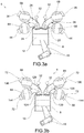
figures 3a, 3b represent partial sectional views of an endothermic engine comprising a full dual distribution system (DDI) according to possible embodiments of the present invention; -
figures 4-11 represent partial sectional views of a sequence of phases of a complete intake-exhaust cycle of an endothermic engine comprising a full dual distribution system (DDI) according to a possible embodiment of the present invention. - The elements or parts of elements in common between the embodiments described hereinafter will be indicated at the same numerical references.
- With reference to the aforementioned figures, a total schematic view of an endothermic engine according to the present invention is collectively indicated at 4.
- For the purposes of the present invention, the type, power and/or displacement of the endothermic engine, as well as the type of vehicle, motorcycle, watercraft or aircraft to which it is intended, are not relevant, even though, as described, the present invention is preferably, but not exclusively, for automotive, motorcycling or other disciplines involving the use of an endothermic engine.
- The
endothermic engine 4 comprises at least onecylinder 8 which houses and drives, according to a reciprocating rectilinear motion, apiston 12 operatively connected to a drive shaft according to a connecting rod/crank mechanism 16, in a known manner. - The
cylinder 8 is provided with at least one firstmain intake valve 20 and at least one firstmain exhaust valve 24, each adapted to close the access to thecylinder 8 and inserted at least partially in a relevant firstmain manifold 28. Typically, the first main intake andexhaust valves camshafts 32, in a known manner. - According to the present invention, at least one of said first main intake and/or
exhaust valves main manifold 28 that forks into anintake channel 36 intercepted by a secondary intake valve 40 and into anexhaust channel 44 intercepted by a secondary exhaust valve 48. - The
intake channel 36 is fluidically connected to an intake system of the engine (not shown) and theexhaust channel 44 is fluidically connected to an exhaust system of the engine (not shown). - It should be noted that depending on the type of cylinder configuration/architecture of the engine (whether in-line, V, Boxer and the like), the intake channel 36 (or intake channels 36) and the exhaust channel 44 (or exhaust channels 44) may be shared, for example, by each cylinder bank of the engine.
- Generally, an intake system is typically an air duct that draws air from the outside environment and conducts it into the combustion chamber through said
intake channel 36 of the firstmain manifold 28, after filtering the air. The filter may be placed, for example, in a suitable filter box upstream of the firstmain manifold 28. - For example, said exhaust system comprises one or more combustion gas collectors that are introduced into an expansion compartment which may, for example, contain one or more treatment devices for combustion gases prior to introducing them into the atmosphere. The combustion gas treatment may also be absent, for example, from vehicles intended for competitions.
- Advantageously, the secondary intake and exhaust valves 40,48 are kinematically connected in synchronism with the respective first main intake and/or
exhaust valve cylinder 8 through theintake channel 36, connected to the firstmain exhaust valve 24, at least partially simultaneously with the inlet of air from the firstmain intake valve 20, and/or to allow the additional exit of combustion gases from thecylinder 8 through theexhaust channel 44, connected to the firstmain intake valve 20, at least partially simultaneously with the exit of combustion gases through the firstmain exhaust valve 24. - The present invention provides, as better described below, the possibility of using a secondary distribution, comprising the aforementioned intake and exhaust valves 40,48 upstream of the primary distribution comprising the intake and
exhaust valves - Such solution may be achieved by a partial dual distribution intake system (DDP-A;
figure 1 ), by a partial dual distribution exhaust system (DDP-S;figure 2 ) and by a full dual distribution system (DDI,figure 3 ) . - In particular, according to a first embodiment, in said partial dual distribution intake system (DDP-A;
figure 1 ), the firstmain intake valve 20 is fluidically connected to amain intake duct 52, while the firstmain exhaust valve 24 is fluidically connected to a firstmain manifold 28 that forks into anintake channel 36 intercepted by a secondary intake valve 40 and into anexhaust channel 44, intercepted by a secondary exhaust valve 48. - Said secondary intake and exhaust valves 40,48 are kinematically connected in synchronism with the first
main intake valve 20 so as to cyclically allow the additional entry of air in thecylinder 8 through theintake channel 36, at least partially simultaneously with the entry of air from the firstmain intake valve 20 through themain intake duct 52, and to allow the exit of combustion gases from thecylinder 8 through theexhaust channel 44. - In particular, according to a further embodiment, in said partial dual distribution exhaust system (DDP-S;
figure 2 ), the firstmain exhaust valve 24 is fluidically connected to a secondmain manifold 56, while the firstmain exhaust valve 20 is fluidically connected to a firstmain manifold 28 that forks into anintake channel 36 intercepted by a secondary intake valve 40 and into anexhaust channel 44 intercepted by a secondary exhaust valve 48. - Said secondary intake and exhaust valves 40,48 are kinematically connected in synchronism with the first
main exhaust valve 24 so as to cyclically allow the additional exit of combustion gases from thecylinder 8 through theexhaust channel 44, at least partially simultaneously with the exit of combustion gases from the firstmain exhaust valve 24 through the secondmain manifold 56, and to allow the entry of air in thecylinder 8 through theintake channel 36. - Preferably, the
engine 4, as shown, comprises a full dual distribution system (DDI;figure 3 ) which provides for the use of firstmain manifolds 28 which engage at both the firstmain intake valve 20 and the firstmain exhaust valve 24, each of which forks into anintake channel 36 and into anexhaust channel 44. Therefore, each firstmain manifold 28 is capable by means of the respective intake andexhaust channels exhaust valves - The foregoing applies both to
engines 4 having two valves per cylinder, i.e. an intake valve and an exhaust valve, and to engines having three, four or even more valves per cylinder. Therefore, for the purposes of the scope of protection of this patent, embodiments having at least two valves per cylinder are protected. - The figures provided in the patent always show an intake valve and an exhaust valve for convenience and greater intelligibility of the figures.
- A preferred embodiment provides for the application of the present invention to an engine having four valves per cylinder.
- For example (
figure 3b ), thecylinder 8 is provided with at least one secondmain intake valve 120 and at least one secondmain exhaust valve 124, wherein at least one of said second main intake and/orexhaust valves main manifold 128 which is forked into asecond intake channel 136 intercepted by a secondary intake valve 40 and into asecond exhaust channel 144 intercepted by a secondary exhaust valve 48. - The
second intake channel 136 is fluidically connected to the intake system of the engine, along with theintake channel 36. - The
second exhaust channel 144 is fluidically connected to the exhaust system of the engine, along with theexhaust channel 44. - Advantageously, said secondary intake and exhaust valves 40,48 are kinematically connected in synchronism with the respective second
main intake 120 and/orexhaust 124 valve so as to cyclically allow the additional entry of air into the cylinder through thesecond intake channel 136, connected to the secondmain exhaust valve 124, at least partially simultaneously with the entry of air from the secondmain intake valve 120, and/or to allow the additional exit of combustion gases from the cylinder through thesecond exhaust channel 144, connected to the secondmain intake valve 120, at least partially simultaneously with the exit of combustion gases through the secondmain exhaust valve 124. - As seen, the main valves are preferably poppet valves.
- The secondary intake and exhaust valves 40, 48 are preferably rotary valves.
- For example, said rotary valves comprise a cylindrical or spherical body 60 defining an
inner channel 64 rotating integrally with the body. Saidinner channel 64 has alumen 68 of a dimension similar to thelumen 72 of the intake channel 36,136 or the exhaust channel 44,144 within which the valve is inserted; in this way, during the rotation of the body 60, theinner channel 64 cyclically passes from an angular orientation where it is at least partially aligned with therelated lumen 72 of the intake channel 36,136 or exhaust channel 44,144 at an angular orientation wherein it is totally misaligned with respect to the latter. - It is evident that the alignment, even partial, is configured as the opening of the rotary valve and allows the incoming air or outgoing exhaust gas to pass through, while the full misalignment is configured as the closing of the rotary valve.
- It should be noted that the outer diameter and the passage diameter of the rotary valves are suitably calibrated and calculated inasmuch as the closing or opening of the duct depends on their relative ratio.
- The system lends itself to being easily adopted in multi-cylinder engines simply by using a cylinder where the through-holes are properly rotated according to the respective crank angle.
- The rotary valves are not subject to strong pressures because the totality of the sealing work remains dependent on the main valves. Therefore, no particularly sophisticated seals are required.
- According to a possible embodiment, said rotary valves are controlled by a main distribution apparatus of the engine comprising at least one
camshaft 32. Preferably, the same camshaft orcamshafts 32 control both themain valves - For example, the secondary intake and exhaust valves 40, 48 are rotary valves actuated at the same rotational speed of at least one
camshaft 32 which controls the actuation of the main valves. In the case of symmetrical rotary valves, the rotation speed of the same could also be reduced to ½ of the camshaft's rotation speed. - Advantageously, the first and second
main manifolds main valve - It should be noted that in the case of an engine with 4 valves per cylinder (typically two intake valves and two exhaust valves), the two
main exhaust valves 24 may have a first common duct intercepted by the same secondary exhaust valves 48; only subsequently to such first common duct will the same duct fork into two branches that will each merge into a single valve. - Preferably, the secondary valves are positioned within the
respective manifolds 28 so as to be away from the corresponding intake 20,120 and/or exhaust 24,124 valves at the minimum possible distance, compatible with the construction and cooling requirements. - Preferably, the secondary valves 40, 48 of a same first
main manifold 28 are mutually phased so as to have a cross phase, i.e. at least a partial opening at the same time, so as to facilitate the emptying of the gases inside the same duct. - In effect, during the exhaust phase, a combustion flow portion may remain trapped in the buffer zone. In order to prevent this air mass from being re-aspirated by the engine, an adequate cross phase is necessary so that the downstream depression of the secondary exhaust valve 48 may empty the buffer.
- In the case of multi-cylinder engines with intake and exhaust ducts shared among the various cylinders, the arrangement of exhaust ducts and phasing of the valves will be suitable in order to avoid that the passive cross phase (i.e. with the main valves closed) coincides with an active exhaust phase (i.e. with the main valves open) of another cylinder having a shared duct.
- Finally, in a known manner, the
engine 4 comprises fuel injector devices (not shown) arranged downstream of said secondary intake valves 40. - In effect, since a certain amount of air could pass from the secondary intake valve 40 to the exhaust without passing through the
engine 4, in order to assure that the buffer ("overflow") is empty, the fuel should only be injected downstream of the secondary intake valve 40 and only when the exhaust valve is completely (or nearly) closed. - Preferably, said injector devices are arranged so as to inject the fuel directly into the cylinder; in this way the problem is completely solved.
- The operation of an endothermic engine according to the present invention will now be described.
- It should be noted that the phasing angles, the lifts and the opening/closing angles of the secondary valves are purely indicative and, in this context, serve solely to better define the operation of the present invention.
- Reference will be made to
figures 4-11 relating to a sequence of phases of a complete intake-exhaust cycle of an endothermic engine comprising a full dual distribution system (DDI) according to a possible embodiment of the present invention. It is evident that the following also applies to the embodiments of endothermic engines comprising partial dual distribution intake (DDP-A) and/or exhaust (DDP-S) system according to the present invention. - In particular,
figure 4 illustrates the beginning of the intake phase, coinciding with the end of the exhaust phase. The main valves are in the maximum lift state, the secondary rotary intake valves are in the opening state (about 5 degrees), and the secondary rotary exhaust valves are in the opening state (about 25 degrees). -
Figure 5 continues with the intake phase and reaches the end of the exhaust phase. The main valves are in maximum lift state, the secondary rotary intake valves are in opening state (about 25 degrees), while the secondary rotary exhaust valves are in closing state. It should be noted that, in the passage from the exhaust phase to the intake phase, the main valves have remained motionless in the open position, thus maximizing the passage area of the fluids. -
Figure 6 again illustrates the intake phase. In particular, the main valves are in maximum lift state and beginning of closure, the secondary rotary intake valves are in the maximum opening state (in other words, the respective inner channel is aligned parallel to the related intake duct in order to allow the maximum lumen of the air passage), while the secondary rotary exhaust valves are closed. As shown, for the purpose of the closing state, it is sufficient that the inner channel of a valve is not, even partially, aligned with the respective channel wherein the rotary valve is inserted. -
Figure 7 shows the end of the intake phase and the beginning of the compression phase. In particular, the main valves are closed, the secondary rotary intake valves are in the closing phase, open about 25 degrees; however, such position is irrelevant as the main valves are closed whereby the duct is fluidically separated from the cylinder. The secondary rotary exhaust valves are closed: also in this case their position is irrelevant.Figure 8 illustrates the end of the compression phase. The main valves are closed, the secondary rotary intake valves and the secondary rotary exhaust valves still have an irrelevant position. -
Figure 9 illustrates the end of the expansion phase coinciding with the beginning of the exhaust phase. The main valves are in the opening state, while the secondary rotary intake valves are in the closing state. The secondary rotary exhaust valves are instead in the opening state. -
Figure 10 shows the exhaust phase. In particular the main valves are in the maximum lift state, the secondary rotary intake valves are closed, while the secondary rotary exhaust valves are in the maximum opening state. - Finally,
figure 11 shows the end of the exhaust phase. The main valves are in the maximum lift state, the secondary rotary intake valves are in the opening state, while the secondary rotary exhaust valves are in the closing state (approximately 25 degrees). - Obviously, the foregoing description refers to the more complex full dual distribution system (DDI), but it may obviously also be extended, with the due omissions, to simpler partial dual distribution intake (DDP-A) and exhaust (DDP -S) solutions.
- As may be appreciated from the description, the endothermic engine according to the invention overcomes the disadvantages of the prior art.
- In particular, the endothermic engine allows the improvement of the volumetric and pumping efficiency with respect to the prior art solutions.
- In the case of a full dual distribution system (DDI), the gas transfer area, both in intake and exhaust, virtually doubles with respect to a standard solution. Even considering the complexity of the system and some loss due to the possible heat exchange with the warmer parts, a conservative estimate could suggest a 10%-15% volumetric increase, as well as a better pumping efficiency in the case of turbocharged engines.
- In the case of a partial dual distribution intake system (DDP-A), the intake passage area virtually doubles, while the exhaust area remains unchanged, the opposite occurs in the case of the partial dual distribution exhaust system (DDP-S). In the first case (DDP-A), only volumetric efficiency is increased: this improvement is certainly notable and useful in case of use on aspirated engines, i.e. not supercharged.
- In any case, the partial dual distribution intake system (DDP-A), with respect to the full dual distribution system (DDI), has greater constructive simplicity, is lighter, and is suitable, as is seen in aspirated engines as well as in those cases where the exhaust outlet of the engine is constrained by constructive or regulatory requirements.
- In the second case of a partial dual distribution exhaust system (DDP-S), only pumping efficiency is increased: such improvement is notable and useful in turbocharged engines.
- In any case, the partial dual distribution exhaust system (DDP-S), with respect to the full dual distribution system (DDI), has greater constructive simplicity, is lighter, and is suitable, as seen in turbocharged engines.
- A person skilled in the art, in the object of satisfying contingent and specific requirements, may make numerous modifications and variations to the engines described above, all of which are within the scope of the invention as defined by the following claims.
Claims (13)
- Endothermic engine (4) comprising- at least one cylinder (8) that receives and guides, according to a reciprocating rectilinear motion, a piston (12) operatively connected to a drive shaft according to a connecting rod/crank mechanism (16), the cylinder (8) being provided with at least one first main intake valve (20) fluidically connected to a first main manifold (28), and at least one first main exhaust valve (24) fluidically connected to a second main manifold (56), wherein
at least one of the first and second main manifold (28, 56) forks into an intake channel (36) and into an exhaust channel (44),- wherein the intake channel (36) is fluidically connected to an intake system of the engine (4), and the exhaust channel (44) is fluidically connected to an exhaust system of the engine (4),
characterized in that
the intake channel (36) is intercepted by a secondary intake valve (40) and the exhaust channel (44) is intercepted by a secondary exhaust valve (48),- said secondary intake and exhaust valves (40,48) being kinematically connected in synchronism with the respective first main intake and/or exhaust valve (20,24) so as to cyclically allow:- the additional entry of air in the cylinder (8) through the intake channel (36), connected to said first main exhaust valve (24), at least partially simultaneously with the entry of air from said first main intake valve (20), and/or to allow- the additional exit of combustion gases from the cylinder (8) through the exhaust channel (44), connected to said first main intake valve (20), at least partially simultaneously with the exit of combustion gases through said first main exhaust valve (24). - Endothermic engine (4) according to claim 1, wherein the first main intake valve (20) is fluidically connected to a main intake duct (52), wherein the first main exhaust valve (24) is fluidically connected to a first main manifold (28) that forks into an intake channel (36) intercepted by a secondary intake valve (40) and into an exhaust channel (44) intercepted by a secondary exhaust valve (48),- said secondary intake and exhaust valves (40,48) being kinematically connected in synchronism with the first main intake valve (20) so as to cyclically allow the additional entry of air in the cylinder (8) through the intake channel (36), at least partially simultaneously with the entry of air from the first main intake valve (20) through the main intake duct (52), and to allow the exit of combustion gases from the cylinder (8) through the exhaust channel (44).
- Endothermic engine (4) according to claim 1 or 2, wherein the first main exhaust valve (24) is fluidically connected to a second main manifold (56), wherein the first main intake valve (20) is fluidically connected to a first main manifold (28) that forks into an intake channel (36) intercepted by a secondary intake valve (40) and into an exhaust channel (44) intercepted by a secondary exhaust valve (48),- said secondary intake and exhaust valves (40,48) being kinematically connected in synchronism with the first main exhaust valve (24) so as to cyclically allow the additional exit of combustion gases from the cylinder (8) through the exhaust channel (44), at least partially simultaneously with the exit of combustion gases from the first main exhaust valve (24) through the second main manifold (56), and to allow the entry of air in the cylinder (8) through the intake channel (36).
- Endothermic engine (4) according to any of the preceding claims, wherein the cylinder (8) is provided with at least one second main intake valve (120) and at least one second main exhaust valve (124),
characterized in that- at least one of said second main intake and/or exhaust valves (120,124) is fluidically connected to a second main manifold (128) that forks into a second intake channel (136) intercepted by a secondary intake valve (40) and into a second exhaust channel (144) intercepted by a secondary exhaust valve (148),- wherein the second intake channel (136) is fluidically connected to an intake system of the engine (4) and the exhaust channel is fluidically connected to an exhaust system of the engine (4),- said secondary intake and exhaust valves (40,48) being kinematically connected in synchronism with the respective second main intake (120) and/or exhaust (124) valve so as to cyclically allow the additional entry of air in the cylinder (8) through the second intake channel (136), connected to the second main exhaust valve (124), at least partially simultaneously with the entry of air from the second main intake valve (120), and/or to allow the additional exit of combustion gases from the cylinder (8) through the second exhaust channel (144), connected to the second main intake valve (120), at least partially simultaneously with the exit of combustion gases through the second main exhaust valve (124). - Endothermic engine (4) according to any of the preceding claims, wherein the main valves (20,120,24,124) are poppet valves, provided with a reciprocating rectilinear motion, and wherein the secondary valves (40, 48) are rotary valves.
- Endothermic engine (4) according to claim 5, wherein said rotary valves (40,48) are controlled by a main distribution apparatus of the engine (4) comprising at least one camshaft (32).
- Endothermic engine (4) according to claim 5 or 6, wherein said rotary valves (40,48) comprise a cylindrical or spherical body (60) that delimits an internal channel (64) that rotates integrally with the body (60), said internal channel (64) having a lumen (68) of similar dimension to the lumen (72) of the intake (36, 136) or exhaust (44,144) channel inside of which the valve is inserted, so that, during rotation of the body (60), the internal channel (64) cyclically passes from an angular orientation wherein it is at least partially aligned with the respective lumen (72) of the intake (36,136) or exhaust (44,144) channel to an angular orientation wherein it is totally misaligned with respect to the latter.
- Endothermic engine (4) according to any of the preceding claims, in which all the main (20,120,24,124) and secondary (40,48) valves are mechanically connected to the same main distribution apparatus for the respective actuation.
- Endothermic engine (4) according to any of the preceding claims, wherein which the secondary valves (40, 48) are rotary valves driven at the same speed of rotation, or at ½ of the speed of rotation of at least one camshaft (32) that controls the actuation of the main valves (20,120,24,124).
- Endothermic engine (4) according to any of the preceding claims, wherein the first main manifolds (28) of each main valve (20,120,24,124) are separated from each other so as not to provide any direct fluidic connection.
- Endothermic engine (4) according to any of the preceding claims, wherein which the secondary valves (40, 48) of a same first main manifold (28) are mutually phased in a suitable manner, so as to facilitate the emptying of the gases inside the first main manifold (28) itself.
- Endothermic engine (4) according to any of the preceding claims, wherein the secondary valves (40,48) are phased so as to provide an intersection phase, i.e., of at least partial simultaneous opening.
- Endothermic engine (4) according to any of the preceding claims, wherein the engine (4) comprises fuel injection devices disposed so as to inject the fuel directly into the cylinder (8).
Applications Claiming Priority (1)
| Application Number | Priority Date | Filing Date | Title |
|---|---|---|---|
| IT102016000108158A IT201600108158A1 (en) | 2016-10-26 | 2016-10-26 | ENDOTHERMAL ENGINE WITH IMPROVED DISTRIBUTION SYSTEM |
Publications (2)
| Publication Number | Publication Date |
|---|---|
| EP3315736A1 EP3315736A1 (en) | 2018-05-02 |
| EP3315736B1 true EP3315736B1 (en) | 2019-12-18 |
Family
ID=58054451
Family Applications (1)
| Application Number | Title | Priority Date | Filing Date |
|---|---|---|---|
| EP17198441.2A Active EP3315736B1 (en) | 2016-10-26 | 2017-10-26 | Endothermic engine with improved distribution system |
Country Status (2)
| Country | Link |
|---|---|
| EP (1) | EP3315736B1 (en) |
| IT (1) | IT201600108158A1 (en) |
Families Citing this family (1)
| Publication number | Priority date | Publication date | Assignee | Title |
|---|---|---|---|---|
| CN114033582B (en) * | 2021-11-12 | 2023-02-03 | 中船动力研究院有限公司 | Gas, ventilative distributor and boats and ships |
Family Cites Families (3)
| Publication number | Priority date | Publication date | Assignee | Title |
|---|---|---|---|---|
| GB191220861A (en) * | 1912-09-13 | 1913-06-26 | Herbert Lindley | Improvements in Valves and Valves-gear for Internal Combustion Engines. |
| US1951759A (en) * | 1931-11-16 | 1934-03-20 | Keister James | Internal combustion engine |
| FR2764937A1 (en) * | 1997-06-20 | 1998-12-24 | Philippe Jean Claude Jaouen | Device for valve control in engine, which, in effect, doubles number of valves |
-
2016
- 2016-10-26 IT IT102016000108158A patent/IT201600108158A1/en unknown
-
2017
- 2017-10-26 EP EP17198441.2A patent/EP3315736B1/en active Active
Non-Patent Citations (1)
| Title |
|---|
| None * |
Also Published As
| Publication number | Publication date |
|---|---|
| EP3315736A1 (en) | 2018-05-02 |
| IT201600108158A1 (en) | 2018-04-26 |
Similar Documents
| Publication | Publication Date | Title |
|---|---|---|
| EP2640934B1 (en) | Two stroke opposed-piston engines with compression release for engine braking | |
| US8256402B2 (en) | Exhaust passage structure of multi-cylinder engine | |
| US6257191B1 (en) | Rotary valve system | |
| EP2119888B1 (en) | Parallel sequential turbocharger architecture using engine cylinder variable valve lift system | |
| US8677749B2 (en) | Exhaust system for an internal combustion engine | |
| US8627659B2 (en) | Engine assembly including exhaust port separation for turbine feed | |
| US8714121B2 (en) | Split-cycle air hybrid V-engine | |
| US9121338B1 (en) | Two-stage turbocharger system for internal combustion engines featuring cylinder deactivation | |
| US20120090320A1 (en) | Turbocharged Combustion System | |
| US20110041491A1 (en) | Heat engine with external hot source | |
| US8925526B2 (en) | Internal combustion engine and method of operating such engine | |
| US5749337A (en) | Barrel type internal combustion engine | |
| RU2638901C2 (en) | Supercharged internal combustion engine and method of operation of supercharged internal combustion engine | |
| CN106168147B (en) | Internal combustion engine and engine system | |
| US5778833A (en) | Water vehicle having a "V" shaped multi-cylinder crankcase scavenging engine | |
| US9784169B2 (en) | Two-port integrated exhaust manifold for an internal combustion engine having three cylinders | |
| US5056472A (en) | 4-cycle 12-cylinder engine | |
| US6736100B2 (en) | Compact tuned air induction system for engine | |
| US5524579A (en) | Air cooled rotary distribution valve for internal combustion engine | |
| EP3315736B1 (en) | Endothermic engine with improved distribution system | |
| US5769039A (en) | V shaped multi-cylinder engine of crankcase compression type | |
| US20060070595A1 (en) | Intake device of multi-cylinder engine | |
| US9689326B2 (en) | Exhaust gas recirculation system with paired cylinders | |
| US20070215078A1 (en) | Methods and apparatus to use engine valves as both intake and exhaust valves | |
| AU2008201574B2 (en) | "Martin" cross-flow, 4 stroke side-valve engine |
Legal Events
| Date | Code | Title | Description |
|---|---|---|---|
| PUAI | Public reference made under article 153(3) epc to a published international application that has entered the european phase |
Free format text: ORIGINAL CODE: 0009012 |
|
| STAA | Information on the status of an ep patent application or granted ep patent |
Free format text: STATUS: THE APPLICATION HAS BEEN PUBLISHED |
|
| AK | Designated contracting states |
Kind code of ref document: A1 Designated state(s): AL AT BE BG CH CY CZ DE DK EE ES FI FR GB GR HR HU IE IS IT LI LT LU LV MC MK MT NL NO PL PT RO RS SE SI SK SM TR |
|
| AX | Request for extension of the european patent |
Extension state: BA ME |
|
| STAA | Information on the status of an ep patent application or granted ep patent |
Free format text: STATUS: REQUEST FOR EXAMINATION WAS MADE |
|
| 17P | Request for examination filed |
Effective date: 20181031 |
|
| RBV | Designated contracting states (corrected) |
Designated state(s): AL AT BE BG CH CY CZ DE DK EE ES FI FR GB GR HR HU IE IS IT LI LT LU LV MC MK MT NL NO PL PT RO RS SE SI SK SM TR |
|
| STAA | Information on the status of an ep patent application or granted ep patent |
Free format text: STATUS: EXAMINATION IS IN PROGRESS |
|
| 17Q | First examination report despatched |
Effective date: 20190218 |
|
| GRAJ | Information related to disapproval of communication of intention to grant by the applicant or resumption of examination proceedings by the epo deleted |
Free format text: ORIGINAL CODE: EPIDOSDIGR1 |
|
| STAA | Information on the status of an ep patent application or granted ep patent |
Free format text: STATUS: GRANT OF PATENT IS INTENDED |
|
| GRAP | Despatch of communication of intention to grant a patent |
Free format text: ORIGINAL CODE: EPIDOSNIGR1 |
|
| INTG | Intention to grant announced |
Effective date: 20190723 |
|
| RAP1 | Party data changed (applicant data changed or rights of an application transferred) |
Owner name: CROSETTA, LUCA |
|
| RIN1 | Information on inventor provided before grant (corrected) |
Inventor name: CROSETTA, LUCA |
|
| GRAS | Grant fee paid |
Free format text: ORIGINAL CODE: EPIDOSNIGR3 |
|
| GRAA | (expected) grant |
Free format text: ORIGINAL CODE: 0009210 |
|
| STAA | Information on the status of an ep patent application or granted ep patent |
Free format text: STATUS: THE PATENT HAS BEEN GRANTED |
|
| AK | Designated contracting states |
Kind code of ref document: B1 Designated state(s): AL AT BE BG CH CY CZ DE DK EE ES FI FR GB GR HR HU IE IS IT LI LT LU LV MC MK MT NL NO PL PT RO RS SE SI SK SM TR |
|
| REG | Reference to a national code |
Ref country code: CH Ref legal event code: EP |
|
| REG | Reference to a national code |
Ref country code: IE Ref legal event code: FG4D |
|
| REG | Reference to a national code |
Ref country code: DE Ref legal event code: R096 Ref document number: 602017009820 Country of ref document: DE |
|
| REG | Reference to a national code |
Ref country code: AT Ref legal event code: REF Ref document number: 1214837 Country of ref document: AT Kind code of ref document: T Effective date: 20200115 |
|
| REG | Reference to a national code |
Ref country code: NL Ref legal event code: MP Effective date: 20191218 |
|
| PG25 | Lapsed in a contracting state [announced via postgrant information from national office to epo] |
Ref country code: LT Free format text: LAPSE BECAUSE OF FAILURE TO SUBMIT A TRANSLATION OF THE DESCRIPTION OR TO PAY THE FEE WITHIN THE PRESCRIBED TIME-LIMIT Effective date: 20191218 Ref country code: GR Free format text: LAPSE BECAUSE OF FAILURE TO SUBMIT A TRANSLATION OF THE DESCRIPTION OR TO PAY THE FEE WITHIN THE PRESCRIBED TIME-LIMIT Effective date: 20200319 Ref country code: BG Free format text: LAPSE BECAUSE OF FAILURE TO SUBMIT A TRANSLATION OF THE DESCRIPTION OR TO PAY THE FEE WITHIN THE PRESCRIBED TIME-LIMIT Effective date: 20200318 Ref country code: FI Free format text: LAPSE BECAUSE OF FAILURE TO SUBMIT A TRANSLATION OF THE DESCRIPTION OR TO PAY THE FEE WITHIN THE PRESCRIBED TIME-LIMIT Effective date: 20191218 Ref country code: NO Free format text: LAPSE BECAUSE OF FAILURE TO SUBMIT A TRANSLATION OF THE DESCRIPTION OR TO PAY THE FEE WITHIN THE PRESCRIBED TIME-LIMIT Effective date: 20200318 Ref country code: LV Free format text: LAPSE BECAUSE OF FAILURE TO SUBMIT A TRANSLATION OF THE DESCRIPTION OR TO PAY THE FEE WITHIN THE PRESCRIBED TIME-LIMIT Effective date: 20191218 Ref country code: SE Free format text: LAPSE BECAUSE OF FAILURE TO SUBMIT A TRANSLATION OF THE DESCRIPTION OR TO PAY THE FEE WITHIN THE PRESCRIBED TIME-LIMIT Effective date: 20191218 |
|
| REG | Reference to a national code |
Ref country code: LT Ref legal event code: MG4D |
|
| PG25 | Lapsed in a contracting state [announced via postgrant information from national office to epo] |
Ref country code: RS Free format text: LAPSE BECAUSE OF FAILURE TO SUBMIT A TRANSLATION OF THE DESCRIPTION OR TO PAY THE FEE WITHIN THE PRESCRIBED TIME-LIMIT Effective date: 20191218 Ref country code: HR Free format text: LAPSE BECAUSE OF FAILURE TO SUBMIT A TRANSLATION OF THE DESCRIPTION OR TO PAY THE FEE WITHIN THE PRESCRIBED TIME-LIMIT Effective date: 20191218 |
|
| PG25 | Lapsed in a contracting state [announced via postgrant information from national office to epo] |
Ref country code: AL Free format text: LAPSE BECAUSE OF FAILURE TO SUBMIT A TRANSLATION OF THE DESCRIPTION OR TO PAY THE FEE WITHIN THE PRESCRIBED TIME-LIMIT Effective date: 20191218 |
|
| PG25 | Lapsed in a contracting state [announced via postgrant information from national office to epo] |
Ref country code: EE Free format text: LAPSE BECAUSE OF FAILURE TO SUBMIT A TRANSLATION OF THE DESCRIPTION OR TO PAY THE FEE WITHIN THE PRESCRIBED TIME-LIMIT Effective date: 20191218 Ref country code: NL Free format text: LAPSE BECAUSE OF FAILURE TO SUBMIT A TRANSLATION OF THE DESCRIPTION OR TO PAY THE FEE WITHIN THE PRESCRIBED TIME-LIMIT Effective date: 20191218 Ref country code: CZ Free format text: LAPSE BECAUSE OF FAILURE TO SUBMIT A TRANSLATION OF THE DESCRIPTION OR TO PAY THE FEE WITHIN THE PRESCRIBED TIME-LIMIT Effective date: 20191218 Ref country code: PT Free format text: LAPSE BECAUSE OF FAILURE TO SUBMIT A TRANSLATION OF THE DESCRIPTION OR TO PAY THE FEE WITHIN THE PRESCRIBED TIME-LIMIT Effective date: 20200513 Ref country code: RO Free format text: LAPSE BECAUSE OF FAILURE TO SUBMIT A TRANSLATION OF THE DESCRIPTION OR TO PAY THE FEE WITHIN THE PRESCRIBED TIME-LIMIT Effective date: 20191218 |
|
| PG25 | Lapsed in a contracting state [announced via postgrant information from national office to epo] |
Ref country code: IS Free format text: LAPSE BECAUSE OF FAILURE TO SUBMIT A TRANSLATION OF THE DESCRIPTION OR TO PAY THE FEE WITHIN THE PRESCRIBED TIME-LIMIT Effective date: 20200418 Ref country code: SK Free format text: LAPSE BECAUSE OF FAILURE TO SUBMIT A TRANSLATION OF THE DESCRIPTION OR TO PAY THE FEE WITHIN THE PRESCRIBED TIME-LIMIT Effective date: 20191218 Ref country code: SM Free format text: LAPSE BECAUSE OF FAILURE TO SUBMIT A TRANSLATION OF THE DESCRIPTION OR TO PAY THE FEE WITHIN THE PRESCRIBED TIME-LIMIT Effective date: 20191218 |
|
| REG | Reference to a national code |
Ref country code: DE Ref legal event code: R097 Ref document number: 602017009820 Country of ref document: DE |
|
| REG | Reference to a national code |
Ref country code: AT Ref legal event code: MK05 Ref document number: 1214837 Country of ref document: AT Kind code of ref document: T Effective date: 20191218 |
|
| PLBE | No opposition filed within time limit |
Free format text: ORIGINAL CODE: 0009261 |
|
| STAA | Information on the status of an ep patent application or granted ep patent |
Free format text: STATUS: NO OPPOSITION FILED WITHIN TIME LIMIT |
|
| PG25 | Lapsed in a contracting state [announced via postgrant information from national office to epo] |
Ref country code: ES Free format text: LAPSE BECAUSE OF FAILURE TO SUBMIT A TRANSLATION OF THE DESCRIPTION OR TO PAY THE FEE WITHIN THE PRESCRIBED TIME-LIMIT Effective date: 20191218 Ref country code: DK Free format text: LAPSE BECAUSE OF FAILURE TO SUBMIT A TRANSLATION OF THE DESCRIPTION OR TO PAY THE FEE WITHIN THE PRESCRIBED TIME-LIMIT Effective date: 20191218 |
|
| 26N | No opposition filed |
Effective date: 20200921 |
|
| PG25 | Lapsed in a contracting state [announced via postgrant information from national office to epo] |
Ref country code: SI Free format text: LAPSE BECAUSE OF FAILURE TO SUBMIT A TRANSLATION OF THE DESCRIPTION OR TO PAY THE FEE WITHIN THE PRESCRIBED TIME-LIMIT Effective date: 20191218 Ref country code: AT Free format text: LAPSE BECAUSE OF FAILURE TO SUBMIT A TRANSLATION OF THE DESCRIPTION OR TO PAY THE FEE WITHIN THE PRESCRIBED TIME-LIMIT Effective date: 20191218 |
|
| PG25 | Lapsed in a contracting state [announced via postgrant information from national office to epo] |
Ref country code: IT Free format text: LAPSE BECAUSE OF FAILURE TO SUBMIT A TRANSLATION OF THE DESCRIPTION OR TO PAY THE FEE WITHIN THE PRESCRIBED TIME-LIMIT Effective date: 20191218 |
|
| PG25 | Lapsed in a contracting state [announced via postgrant information from national office to epo] |
Ref country code: PL Free format text: LAPSE BECAUSE OF FAILURE TO SUBMIT A TRANSLATION OF THE DESCRIPTION OR TO PAY THE FEE WITHIN THE PRESCRIBED TIME-LIMIT Effective date: 20191218 |
|
| REG | Reference to a national code |
Ref country code: CH Ref legal event code: PL |
|
| PG25 | Lapsed in a contracting state [announced via postgrant information from national office to epo] |
Ref country code: LU Free format text: LAPSE BECAUSE OF NON-PAYMENT OF DUE FEES Effective date: 20201026 Ref country code: MC Free format text: LAPSE BECAUSE OF FAILURE TO SUBMIT A TRANSLATION OF THE DESCRIPTION OR TO PAY THE FEE WITHIN THE PRESCRIBED TIME-LIMIT Effective date: 20191218 |
|
| REG | Reference to a national code |
Ref country code: BE Ref legal event code: MM Effective date: 20201031 |
|
| PG25 | Lapsed in a contracting state [announced via postgrant information from national office to epo] |
Ref country code: BE Free format text: LAPSE BECAUSE OF NON-PAYMENT OF DUE FEES Effective date: 20201031 Ref country code: CH Free format text: LAPSE BECAUSE OF NON-PAYMENT OF DUE FEES Effective date: 20201031 Ref country code: LI Free format text: LAPSE BECAUSE OF NON-PAYMENT OF DUE FEES Effective date: 20201031 |
|
| PG25 | Lapsed in a contracting state [announced via postgrant information from national office to epo] |
Ref country code: IE Free format text: LAPSE BECAUSE OF NON-PAYMENT OF DUE FEES Effective date: 20201026 |
|
| PG25 | Lapsed in a contracting state [announced via postgrant information from national office to epo] |
Ref country code: TR Free format text: LAPSE BECAUSE OF FAILURE TO SUBMIT A TRANSLATION OF THE DESCRIPTION OR TO PAY THE FEE WITHIN THE PRESCRIBED TIME-LIMIT Effective date: 20191218 Ref country code: MT Free format text: LAPSE BECAUSE OF FAILURE TO SUBMIT A TRANSLATION OF THE DESCRIPTION OR TO PAY THE FEE WITHIN THE PRESCRIBED TIME-LIMIT Effective date: 20191218 Ref country code: CY Free format text: LAPSE BECAUSE OF FAILURE TO SUBMIT A TRANSLATION OF THE DESCRIPTION OR TO PAY THE FEE WITHIN THE PRESCRIBED TIME-LIMIT Effective date: 20191218 |
|
| PG25 | Lapsed in a contracting state [announced via postgrant information from national office to epo] |
Ref country code: MK Free format text: LAPSE BECAUSE OF FAILURE TO SUBMIT A TRANSLATION OF THE DESCRIPTION OR TO PAY THE FEE WITHIN THE PRESCRIBED TIME-LIMIT Effective date: 20191218 |
|
| PGFP | Annual fee paid to national office [announced via postgrant information from national office to epo] |
Ref country code: FR Payment date: 20221020 Year of fee payment: 6 |
|
| PGFP | Annual fee paid to national office [announced via postgrant information from national office to epo] |
Ref country code: GB Payment date: 20231020 Year of fee payment: 7 |
|
| PGFP | Annual fee paid to national office [announced via postgrant information from national office to epo] |
Ref country code: DE Payment date: 20231020 Year of fee payment: 7 |